Embed Size (px)
Citation preview

On the Mechanical Stabilityof Inclined Wellbores
Shaohua Zhou,' R.R. Hillis, and Mike Sandiford, U. of Adelaide (Australia)
Summary
Consideration of the stress field around an arbitrarily oriented bore-hole shows that in an extensional stress regime (av> OH> ah), well-bores parallel to the direction of minimum horizontal principalstress are the least prone to compressive shear failure (breakout).The most stable deviation angle (from the vertical) depends on theratio of the horizontal principal stresses to the vertical stresses, andthe higher the ratio oH/av, the higher the deviation angle for mini-mizing breakout. In a strike-slip stress regime (OH> av >Oh), hori-zontal wells are the least prone to breakout, and the higher the ratiooH/av, the closer the drilling direction should be to the azimuth ofOH·
A new compressive shear failure criterion, which is a combina-tion of the effective strength concept and the Drucker-Prager criteri-on, is proposed for quantifying the stresses at which borehole break-out occurs. The lowest mud weight, at and below which breakoutwill occur, can be predicted by combining this criterion with thestress field around an arbitrarily oriented borehole. The highest mudweight at and above which a tensional or hydraulic fracture is in-duced can be predicted by combining the tensile strength of therocks of the wellbore wall with the stress field around an arbitrarilyoriented borehole. For the in-situ stress environments considered,the optimallY oriented inclined well bore is less prone to breakout(i.e., allows a lower mud weight) and tensional or hydraulic fracture(i.e., supports a higher mud weight) than a vertical well.
Introduction
It has been widely recognized that highly deviated, extended-reachand horizontal wells can offer economic benefits through lowerfield development costs, faster production rates, and higher recov-ery factors. I ,2 However, inclined and horizontal wells may be proneto mechanical instability problems associated with the in-situ stressfield. Hence, an understanding and analytical design capability tomanage wellbore stability in high in-situ stress fields should helprealize the full benefits offered by current and emerging inclinedwell drilling technology.
Much progress has recently been made toward the determinationof the magnitude and orientation of in-situ stress in the crust, in par-ticular, by borehole breakout analyses and hydraulic fracturingtechniques including modified leak-offtests.3-g With knowledge ofthe in-situ stress field, the most stable inclined well trajectory canbe designed. In this paper, the concept of minimum stress anisotropyaround the inclined wellbore wall is introduced. The condition ofminimum stress anisotropy can be used to determine an optimumdrilling direction and deviation angle. In this study, an elastic analyt-ical approach is adopted for mode ling the stress field of deviatedwells in various stress regimes. By combining the effective strengthconcept9 with the widely used Drucker-Prager failure criterion,1O anew failure criterion for rocks is presented and tested with availablerock strength data, Appropriate mud weights for mechanicallystable wells can be determined based on this criterion.
Stress Field Around an Arbitrarily Oriented Borehole
The three principal stresses are usually oriented vertically and hori-zontally because the Earth's surface is a free surface.ll Although
'Now at Geologicallnsl., U. of Copenhagen (Denmark).
Copyright 1996 Society of Petroieum Engineers
Original SPE manuscript received for review Jan. 20, 1994. Revised manuscript receivedNov. 28, 1995. Paper (SPE 28176) peer approved Jan. 24. 1996.
SPE Drilling & Completion, June 1996
this may not be the case near the surface, particularly in areas of ex-treme topography, it has since been confirmed by numerous in-situstress measurements, 12-14 and is further supported by the vast ma-jority of intraplate crustal earthquake focal mechanisms. IS In thispaper, we assume that the principal stresses in the upper few kilome-ters of the Earth's crust generally act in the vertical and two orthogo-nal horizontal directions.
Based on this assumption, and the assumption that rock is isotrop-ic and behaves like a linear elastic material up to the point of failure,an analytical solution of the stress field around an arbitrarily ori-ented borehole can be obtained.16-20 The following summarizes thestress solution and coordinate system used in this paper.
For an arbitrarily oriented borehole, the rotation of the stress ten-sor from the global in-situ coordinate system to a local boreholecoordinate system (Fig, 1) is given by21
cos2 ß sin2acos2a
sin2 ß sin2asin a cos a sinßsinß cosß sin2asina cosa cosß
sin2ßO
cos2ßO
- sinßcosßO
cos2 ß cos2 asin2a
sin2 ß cos2 a- sin a cos a sin ßsinß cos ß cos2 a
- sinacosacosß
{av}~: . . (I)
Following these equations, the stress field at the wall of the bore-hole is given by
Or = ßp, (2)
Oe = 0, + 0, - 2(ox - 0,.) cos 28 - 4fX).sin 28 - !'lp, .. (3)
(4)
fez' = 2( - fxzsin8 + fyzcos8), (5)
f re = O, (6)
and frz, = O. (7)
Based on the above equations, the effective principal stresses onthe borehole wall (which are orthogonal to each other) in the localborehole coordinate system can be expressed by
O2 = !(oe + Oz,) - !¡(oe - O} + 4f~z" (9)
and 03 = Or' (la)
The above solutions assume that the effective fluid pressure in theborehole is the effective minimum principal stress. However, if thispressure is sufficiently high (such as in the generation of hydraulicfractures), it may become the intermediate principal stress.
67
ß
y
8x
A / Oh
°B
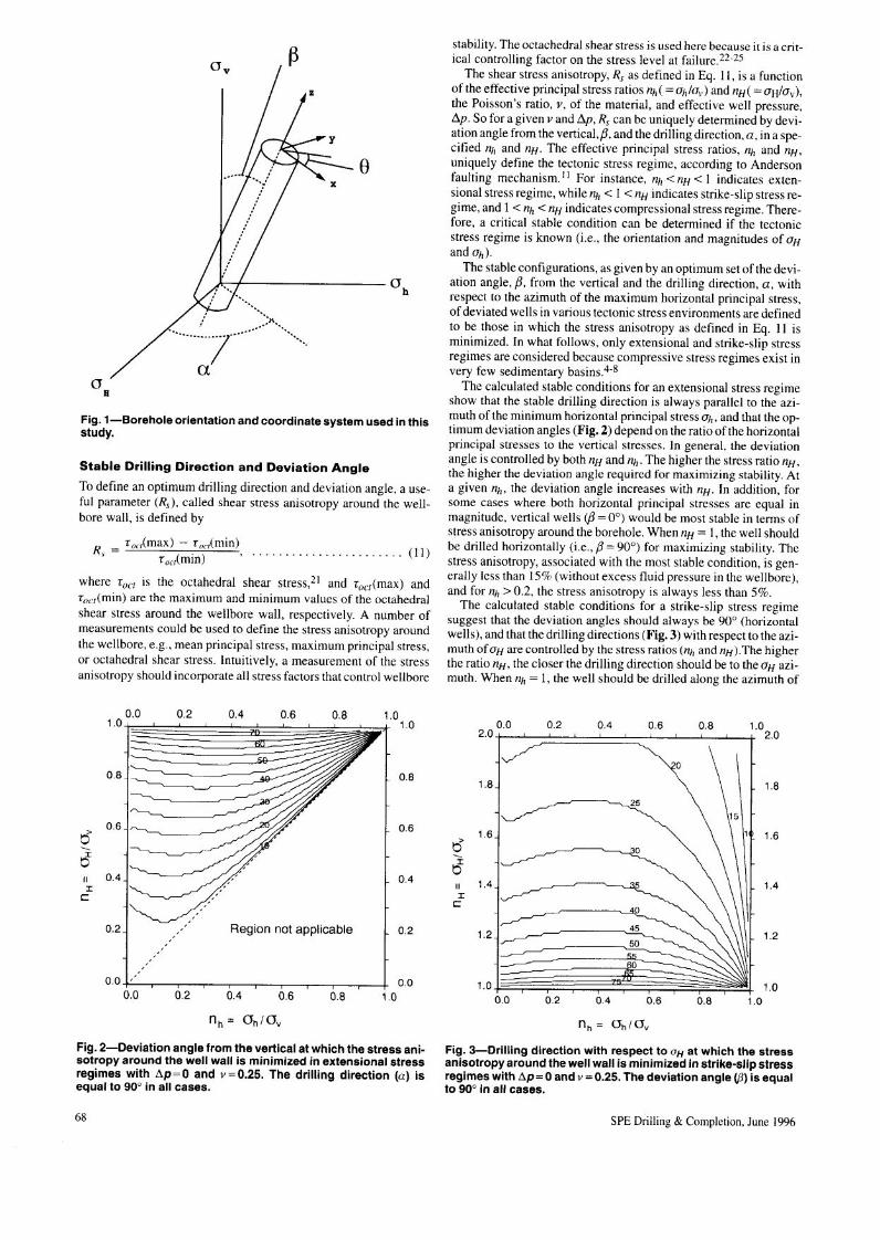
Fig. 1-Borehole orientation and coordinate system used in thisstudy.
Stable Drilling Direction and Deviation Angle
To define an optimum drilling direction and deviation angle, a use-ful parameter (Rs), called shear stress anisotropy around the well-bore wall, is defined by
f oC/(max) - f ouCmin)R, = foc,(min) (Il)
where fact is the octahedral shear stress,21 and foct(max) andfoc/(min) are the maximum and minimum values of the octahedralshear stress around the wellbore wall, respectively. A number ofmeasurements could be used to define the stress anisotropy aroundthe wellbore, e.g., mean principal stress, maximum principal stress,or octahedral shear stress. Intuitively, a measurement of the stressanisotropy should incorporate all stress factors that control wellbore
0.0 .~1.0~~ ~~
~ en----
0.2 0.4 0.6 0.8 1.01.0
::J3~~~¡OB
Ô06
~II OA~ ~~ ,/[ L 004:r:e
~'
0.2 Region not applicable L 0.2
0.0 ' 0.00.0 0.2 0.4 0.6 0.8 10
Fig, 2-Deviation angle from the vertical at which the stress ani-sotropy around the well wall is minimized in extensional stressregimes with tlp=O and v=O.25. The drilling direction (a) isequal to 90° in all cases.
68
stability. The octachedral shear stress is used here because it is a crit-ical controlling factor on the stress level at failure.22-25
The shear stress anisotropy, Rs as defined in Eq. Il, is a functionof the effective principal stress ratios nh( =Oh/Ov) and nH( = oH/av),the Poisson's ratio, Y, of the material, and effective well pressure,!'lp. So for a given Y and !'lp, Rs can be uniquely determined by devi-ation angle from the vertical,ß, and the drilling direction, a, in a spe-cified nh and nH. The effective principal stress ratios, nh and nH,uniquely define the tectonic stress regime, according to Andersonfaulting mechanism.11 For instance, nh < nH < I indicates ex ten-sional stress regime, while nh < I < nH indicates strike-slip stress re-gime, and I < nh < nH indicates compressional stress regime. There-fore, a critical stable condition can be determined if the tectonicstress regime is known (i.e., the orientation and magnitudes of OH
and ah)'The stable configurations, as given by an optimum set of the devi-
ation angle, ß, from the vertical and the drilling direction, a, withrespect to the azimuth of the maximum horizontal principal stress,of deviated wells in various tectonic stress environments are definedto be those in which the stress anisotropy as defined in Eq. II isminimized. In what follows, only extensional and strike-slip stressregimes are considered because compressive stress regimes exist invery few sedimentary basins.4-8
The calculated stable conditions for an extensional stress regimeshow that the stable drilling direction is always parallel to the azi-muth of the minimum horizontal principal stress ah, and that the op-timum deviation angles (Fig. 2) depend on the ratio of the horizontalprincipal stresses to the vertical stresses. In general, the deviationangle is controlled by both nH and nh. The higher the stress ratio nH,the higher the deviation angle required for maximizing stability. Ata given nh, the deviation angle increases with nH. In addition, forsome cases where both horizontal principal stresses are equal inmagnitude, vertical wells (ß = 0°) would be most stable in terms ofstress anisotropy around the borehole. When nH = I, the well shouldbe drilled horizontally (i.e., ß = 90°) for maximizing stability. Thestress anisotropy, associated with the most stable condition, is gen-erally less than 15% (without excess fluid pressure in the wellbore),and for nh > 0.2, the stress anisotropy is always less than 5%.
The calculated stable conditions for a strike-slip stress regimesuggest that the deviation angles should always be 90° (horizontalwells), and that the drilling directions (Fig. 3) with respect to the azi-muth of OH are controlled by the stress ratios (nh and nH ).The higherthe ratio nH, the closer the drilling direction should be to the OH azi-muth. When nh = I, the well should be drilled along the azimuth of
~O I2.01! ~
,.r-'
0.2 004 0.6 0.8 1.02.0
ÔJ~~ \\u::
~I~ 1A~ ~e
"- \ \ \ \~ 104
1.2J ~~\\11.2
1.0~~0.0 i 0.2 i
0415~'-1 .6 0.8 .01.0
Fig. 3-Drilling direction with respect to OH at which the stressanisotropy around the well wall is minimized in strike-slip stressregimes with tlp = Oand v = 0.25. The deviation angle (13) is equalto 90° in all cases.
SPE Drilling & Completion, June 1996
2I 7 I 2
2I I 2
lzumi sandstone(Takahashi & Koide, 19891
2t------~-----___tl 2
Shirahama sandstone (Takahashl & Koide, 1989)
8B
Il-' 1
8 8B
Il-' 1 .".,.....
1
(o, + O 1°2 + 03) 13Co1
(o, +0.102 + 03) 13Co1
(o, + O 102 + 03) I 3Co
2I I 2
Solenhofen Limestone (Magi, 1971)
2I I 2
oO
Dunham Dolomite (Magi, 1971)
3i :> I 2
Mizuho trachyte (Magi. 1972)
8B
Il-' 1
8
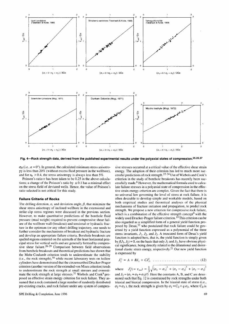
Fig. 4-Rock strength data, derived from the published experimental results under the polyaxial states of compresSiOn.25,35,37
OH (i.e., a = 0°). In general, the calculated minimum stress anisotro-py is less than 20% (without excess fluid pressure in the wellbore),and for nh > 0.4, the stress anisotropy is always less than 5%.
Poisson's ratio v has been taken to be 0.25 in the above calcula-tions; a change of the Poisson's ratio by ± O. I has a minimal effecton the stress field of deviated wells. Hence, the value of Poisson'sratio selected is not critical for this study.
Failure Criteria of RocksThe drilling direction, a, and deviation angle, ß, that minimize theshear stress anisotropy of inclined wellbore in the ex tensional andstrike-slip stress regimes were discussed in the previous section.However, to make quantitative predictions of the borehole fluidpressure (mud weight) required to prevent compressive shear fail-ure of the wellbore wall (breakout) and tensional or hydraulic frac-ture in the optimum (or any other) drilling trajectory, one needs tofurther consider the mechanisms of breakout and hydraulic fractureand develop an appropriate failure criteria. Borehole breakouts arespalled regions centered on the azimuth of the least horizontal prin-cipal stress for vertical wells and are generally formed by compres-sive shear failure.26-29 Comparison between field observationsfrom borehole breakouts and theoretical predictions has shown thatthe Mohr-Coulumb criterion tends to underestimate the stability(i.e., the rock strength),30 while recent laboratory tests on hollowcylinders have demonstrated that the circumscribed Drucker-Pragercriterion (another version of the extended von Mises criterion) tendsto underestimate the rock strength at small stresses and overesti-mate the rock strength at large stresses.31 Wiebols and Cook9 pro-posed an effective strain energy criterion for rock failure. They as-sumed that a rock contained a large number of randomly distributedpre-existing cracks, and rock failure under any system of compres-
SPE Drilling & Completion, June 1996
sive stresses occurred at a critical value of the effective shear strainenergy. The adoption of their criterion has led to much more suc-cessful predictions of rock strength.Z2-Z4Use ofWiebols and Cook'scriterion in the study of borehole breakouts has recently been suc-cessfully made.6 However, the mathematical formula used to calcu-late failure stresses in a polyaxial state of compression in the effec-tive strain energy criterion are complex. Given the fact that there isno universal law governing the level of stress at rock failure, it isoften desirable to develop simple and workable models, based onboth empirical studies and theoretical analyses of the physicalmechanisms of fracture initiation and propagation, to predict rockstrength. We propose a new criterion for compressive rock failure,which is a combination of the effective strength concept9 with thewidely used Drucker-Prager failure criterion.1O This criterion can bealso regarded as a simplified form of a general yield function pro-posed by Desai,32 who postulated that rock failure could be gov-erned by a yield function expressed as a polynomial of the threestress invariants, J¡, }Z, and 1}. A truncated form of Desai's yieldfunction is adopted here, that is, the yield function is simply givenby f(JI,}z) = O, on the basis that only JI and}z, have obvious physi-cal significance, being directly related to the dilatational and distor-tional elastic strain energy, respectively,21 Our new yield functionis expressed by
fi' = A + Bll + elT, (I2)
'h _ _ I j( )2 (. )2 ( )2where J2(- foct) - 3' al - 03 + al - O2 + O2 - 03
and J¡ = (al +02 + 03)13. Here the constants A, B, and C are deter-mined such that Eq. 12 is constrained by rock strengths under bothtriaxial and biaxial compression. In the triaxial state of stress (i.e.,Oz =03 ), the rock strength is given by al = Co + q a3, where Co is
69
o 1 2 341 I 4
A: 03 / Co = 0.0B : 03 / Co = 0.1 b = 0.68e : 03 / Co = 0.2 µ = 0.567O : 03 / Co = 0.3
3J ~ 3/
/o
J- - -- /() - -
.~'
/-- / .......... -------........."" /
Ó / .. ::,.. - - - ... //;iII" _ ..... .. .. /
I~' // ,- -'.'/0 L 2, /
/e
//
//
// solid line = experimental model
/ / long-dash = Wiebols and Cook's model/ short-dash = new model
/
o I" Io 2 3
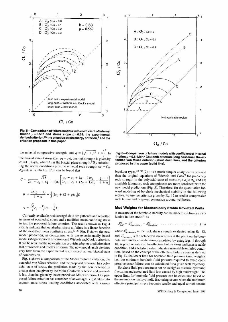
Fig. S-Comparison of failure models with coefficient of internalfriction µ = 0.567 and stress slope b = 0.68: the experimentalderived criterion,35the effective strain energy criterion,9 and thecriterion proposed in this paper.
2the uniaxial compressive strength, and q = (jI+µï + µ) . In
the biaxial state of stress (i.e., al = 02), the rock strength is given byal = Cl + q03, where Cl is the biaxial plane strength.9 By substitut-ing the above conditions plus the uniaxial rock strength (al = Co,02 = 03 = O) into Eq. 12, it can be found that
!ï8 [CI-CO+(q-I)03 q-l]C = 2cI - Co + (q - 1)03 2c] - Co + (2q + 1)03 - 2 + q
fi (q - I) _ 1[2co + (2 + q)03]CB = ~. 3
fi Co cöA=-c --B--C3 o 3 9'
Currently available rock strength data are gathered and replottedin terms of octahedral stress and a modified mean confining stressto test the proposed failure criterion. The results shown in Fig. 4clearly indicate that octahedral stress at failure is a linear functionof the modified mean confining stress.33-3? Fig. 5 shows the newmodel prediction, in comparison with the experimentally basedmodel (Magi empirical criterion) and Wiebols and Cook's criterion.It can be seen that the new criterion provides a better prediction thanthat ofWiebols and Cook's criterion. The new model result deviatesvery little from the experimental result except at near biaxial stateof compression.
Fig. 6 shows a comparison of the Mohr-Coulomb criterion, theextended van Mises criterion, and the proposed criterion. In a poly-axial state of stress, the prediction made by the new criterion isgreater than that given by the Mohr-Coulomb criterion and general-ly less than that given by the extended van Mises criterion. Our pro-posed failure criterion has a number of advantages: (I) it takes intoaccount most stress loading conditions associated with various
70
5 n 2
o
A: 03 /Co = O e- -
4J B : 03 / Co = 0.1 - - L 4-e : 03 I Co = 0.2 - - B
- --- -- --- - Ao
'1- - - - - L 3- -() - - - ,- - - - --- - - - - -,
t5 - - -, , -, - --, - -~
2J y--'" )i ~ 2
B
oNot applicable region
o 2
Fig. 6-Comparison of failure models with coefficient of internalfriction µ=0.6: Mohr-Coulomb criterion (long dash line), the ex-tended von Mises criterion (short dash line), and the criterionproposed in this paper (solid line).
breakout types,38-40 (2) it is a much simpler analytical expressionthan the original equations of Wiebols and Cook9 for predictingrock strength in the polyaxial state of stress 01 >Oz > 03, and (3)available laboratory rock strength tests are more consistent with thenew model predictions (Fig. S). Therefore, for the quantitative for-ward modeling of borehole mechanical stability in the followingsection we use the criterion given by Eq. 12 to predict compressiverock failure and breakout generation around wellbores.
Mud Weights for Mechanically Stable Deviated WellsA measure of the borehole stability can be made by defining an ef-fective failure stresslO as
j'{~ff = Jr;Ockfailure- Jr;"'rehole' ...........•.......... (13)
whereJr;ockfailureis the rock shear strength evaluated using Eq. 12,and J~~orehole is the octahedral shear stress at the point on the bore-hole wall under consideration, calculated by using Eqs. I through10. A positive value of the effective failure stress indicates a stablecondition, and a negative value indicates an unstable or failed condi-tion. Based on the concept of the effective failure stress as definedin Eq. 13, the lower limit for borehole fluid pressure (mud weight),i.e., the minimum borehole fluid pressure required to avoid com-pressive shear failure, can be calculated for a given well trajectory.
Borehole fluid pressure must not be so high as to cause hydraulicfracturing and associated fluid loss caused by high mud weight. Theupper limit for borehole fluid pressure can be calculated based onthe assumption that hydraulic fracturing occurs when the minimumeffective principal stress becomes tensile and equal to rock tensile
SPE Drilling & Completion, June 1996

1.0 1.5 2.0 2.5 3.0 1.0 1.5 2.0 2.5 3.0O O
01
I I
rO
Ishort dash:;:: vertical well short dash = vertical weU Ilongdash = deviatedwell long dash = deviated weill
I
III
Upper.. Upper ; BoundI \ "
I" BoundI \ "I' Lów~Bound
I"I
\\\ I \1\ I I\\ I I
~
'1\\ I Ê \\\ I 2 -" \
l.r: I'. I~ 2 \ 2
Ö. .r: , ,I" I Ö. I . ,Q) , ,O I'. I Q) I ' ,O
"I' I I ""I', I I "
Lower Bound I
\'\I, II', 1
3J I' I 3I' I 3 L 3I: 1I' II' II' I \I', I\: II: I
4 I: 4 I I
2.5 3.0 4 I 41.0 1.5 2.01.0 1.5 2.0 2.5 3.0
equivalent drilling mud density (g/cm'3)
Fig. 7-Mud weight stability profile for vertical and optimally de-viated wells for stress ratios nH =0.9 and nh =0.5 and effectivevertical stress gradient = 12 MPalkm. The rock strength parame-ters are Co = 20 MPa (uniaxial compressive rock strength),µ = 0.6 (coefficient of internal friction), and T= O (tensilestrength). The deviated well trajectory (a = 90° andß = 55°) is thatgiven by the optimum set of drilling direction and deviationangle as shown in Fig. 2 for the given stress ratios nH and nh'Pore pressure is assumed to be hydrostatic. It should be men-tioned that there is no compressive shear failure at shallowdepth less than 1 km for the given stress field and rock strengthparameters. The recommended upper mud weight for the de-viated well is given by the overburden pressure (Le., bulk rockdensity of 2.22 glcm3 derived from the given effective verticalstress and pore pressure), hence, in this case horizontal fracturewould be readily induced by excessive mud weight (see text forfurther discussion).
strength.ll Such rock tensile strength can be derived from the un-confined compressive strength (i.e., T= Co/I2, based on the ex-tended Griffith criterion) or directly measured by extended leakofftest. However, for previously fractured rocks, T= O, and this valueis used in our calculations to provide an upper limit for mud weight.In addition, to avoid horizontal hydraulically induced fractures, themud weight should not be higher than the overburden pressure.2lAI
Hence, the upper mud weight limit is taken as the lower of the valuesof bulk rock density or that calculated from the tangential stress de-scribed above.
As examples, the lower and upper mud weight limits for wellsdrilled in the optimum trajectories with respect to mechanical stabil-ity in two tectonic stress regimes have been calculated (Figs. 7 and8). In a tectonic stress regime of relati vely large anisotropy, well boremechanical stability can be improved by inclined wells drilled withoptimum drilling direction and deviation angle. High in-situ stressesmay create a less stable environment for vertical wells. The mudweight stability field associated with the optimum drilling directionand deviation angle, much wider than that for vertical wells, showsthe importance of drilling trajectory to the mechanical stability ofthe well bore.
Conclusions
In this paper, we have presented a straightforward methodology todeal with the mechanical stability of inclined wells. It has beenshown that mechanical stability can be improved by adopting opti-
SPE Drilling & Completion, June 1996
equivalent drilling mud density (g/cm'3)
Fig. 8-Mud weight stability profile for vertical and optimally de-viated wells for stress ratios nH = 1.1 and nh =0.5. The deviatedwell trajectory (a = 55° and ß = 90°) is that given by the optimumdrilling direction and deviation angle as shown in Fig. 3 for thegiven stress ratios nH and nh' The diagram is otherwise the sameas in Fig. 7.
mum deviation angle and drilling direction. Based on a new com-pressi ve rock failure criterion presented here, our predictions onmud weight stability profiles show that, contrary to intuitive ex-pectation, regions of high tectonic stress anisotropy may produce amore stable environment for inclined wells than vertical wells. Ob-viously, mechanical stability will not generally be the primary factorin selecting well trajectory. For example, deviated wells may be tar-geted to access reservoirs remote from surface facilities or orientedsuch as to maximize intersection with open natural fractures. Themethodology presented here allows mechanically safe mud weightlimits to be determined for a well in any trajectory. It should be notedthat it has been shown elsewhere42 that the well trajectory that maxi-mizes intersection with open, natural, or hydraulically induced frac-ture is consistent with the optimum drilling direction and deviationangle in both the extensional and the strike-slip stress regimes where0.9<nH<I.1.
The conclusion herein applies only to isotropic rocks with linearelasticity up to the point of failure. In the real earth, the rock proper-ties are often complex because of various geological processes.43For material with a Young's modulus depending on the effectivemean stress, the stress field around a well has been shown to be low-er than the prediction based on linear elasticity.44-45 From the stabil-ity point of view, this would tend to increase the stability of the de-viated wells because of the reduction of stress concentration arounda wellbore. Temperature fluctuations associated with mud circula-tion during drilling will not influence the stress anisotropy aroundthe wellbore because the temperature effect should alter the tangen-tial and vertical stresses by an equal amount. However, rock proper-ties may be altered as a result of temperature changes, which mayincrease or reduce the possibility of mechanical failure, dependingon the actual effect on the rock properties.43
Nomenclature
Co = uniaxial rock compressive strength, mlLtZ,MPa
71
Cl = biaxial plane strength, mlLt2, MPa
JI = mean effective confining stress, mlLt2, MPa
nh = ratio of the effective minor horizontalprincipal stress to the effecti ve verticalstress
nH = ratio of the effective major horizontalprincipal stress to the effective verticalstress
ßp = excess fluid pressure in the borehole (i.e., mudpressure less pore pressure in the formation),mlLt2, MPa
Rs = shear stress anisotropy around the wellborewall
T= rock tensile strength, mlLt2, MPa
a = the angle between OH and the projectionof the bore hole axis onto the horizontalplane
ß = the angle between the borehole axis and thevertical direction
8 = polar angle in the borehole cylindricalcoordinate system
µ= coefficient of internal friction
v = Poisson's ratio
OH = effective major horizontal principal stress,mlLt2, MPa
Oh = effective minor horizontal principal stress,mlLtZ, MPa
Or, oe, Oz', Oe;z'.
Orf). Orz' = stress tensor in the borehole cylindricalcoordinate system, mlLtZ, MPa
av = effective vertical stress, mlLtZ, MPa
ox, ay, o;z.Oxy,
oxz 0vz = stress tensor in the borehole Cartesian. . coordinate system, mlLtZ, MPa
al = effective maximum principal stress in theborehole cylindrical coordinate system,mlLtZ, MPa
02 = effective intermediate principal stress in thebore hole cylindrical coordinate system,mlLtZ, MPa
03 = effective minimum principal stress in theborehole cylindrical coordinate system,mlLt2, MPa
fact (= J~') = octahedral shear stress, mlLt2, MPa
Acknowledgments
This study was supported by the Australian Petroleum CooperativeResearch Centre (APCRC). Two anonymous reviewers are thankedfor their helpful comments, with which this manuscript has been im-proved significantly.
References
1. Land, W.J. and Jett, M.B.: "High Expectations for Horizontal DrillingBecoming Reality," Oil Field J. (Sept. 24, 1990) 7(}""79.
2. Joshi, S.O.: "Overview and Application of Horizontal Wells," Geologi·cal Aspects of Horizontal Drilling, R.O. Fritz, M.K. Hom, and S.O. Jo-shi (eds.), AAPG Cont. Educ. Course Note Ser. (1991) 33, 51-64.
3. Zoback, M.D. et al.: "Wellbore Breakouts and In-Situ Stress," J. Geo-phys. Res. (1985) 90, 5523-5530.
4. Barton, C.A., Zoback, M.O., and Burns, K.L.: "In-Situ Stress Orienta-tion and Magnitude at the Fenton Geothermal Site, New Mexico, Deter·mined From Wellbore Breakouts," Geophys. Res. Let!. (1988) 15,467-470.
72
5. Moos, D. and Zoback. MD.: "Utilization of Observations of WellboreFailure To Constrain the Orientation and Magnitude of Crustal Stresses:Application to Continental, Deep Sea Drilling Project. and Ocean Drill-ing Program Boreholes," 1. Geophys. Res. (1990) 95, 9305-9325.
6. Vernik, L. and Zoback. M.O.: "Estimation of Maximum HorizontalPrincipal Stress Magnitude From Stress-Induced Wellbore Breakouts inthe Cajon Pass Scientific Research Borehole," 1. Geophys. Res. (1992)97,5109-5119.
7. Hillis, R. and Williams, A.: 'The Stress Field of the North West Shelfand Wellbore Stability," APEA 1. (1993) 33,373-385.
8. Enever, J.R.: "Case Studies of Hydraulic Fracture Stress Measurementin Australia," Comprehensive Rock Engineering. J.A. Hudson (ed.) Per·gamon Press (1993) 3, 497-531.
9. Wiebols, G.A. and Cook, N.G.W.: "An Energy Criterion forthe Strengthof Rock in Polyaxial Compression," Jnt. 1. Rock Mech. Min. Sei. (1968)5,529-549.
10. Bradley, W.B.: "Failure of Inclined Boreholes," Trans .. ASME (1979)101,232-239.
1I. Anderson, E.M.: The Dynamics of Faulting and Dyke Formation, (sec-ond edition), Oliver and Boyd, London (195 I) 206.
12. Obert, L.: "Determination of Stress in Rock-A State of the Art Re-port," ASTM, Special Technical Publication (1967) No. 429.
13. Greiner, G.: "In-Situ Stress Measurements in Southwest Germany."Tectonophysics (1975) 29, 49-58.
14. Gysei, M.: "In-Situ Stress Measurements of the Primary Stress State inthe Sonnenberg Tunnel in Lucerne, Switzerland," Tectonophysics(1975) 29, 301-314.
15. Zoback, M.L. et al.: "Global Patterns of Tectonic Stress," Nature (1989)341,291-298.
16. Hiramatsu, Y and Oka, Y: "Determination of the Stress in Rock Unaf-fected by Boreholes or Drifts From Measured Strains or Deformations,"Jnt. J. Rock Mech. Min. Sci. (1968) 5, 337-353.
17. Fairhurst, c.: "Methods of Determining In-Situ Rock Stress at GreatDepths," TRI·68, Missouri River Div. Corps of Engineers (1968).
18. Aadnoy, B.S. and Chenevert, M.E.: "Stability of Highly Inclined Bore-holes," SPEDE (1987) 2, 364-374.
19. Mastin, L.: "Effect of Borehole Deviation on Breakout Orientations," J.Geophys. Res. (1988) 93, 9t87-9195.
20. Baumgatner, J., Carvalho, J. and McLennan, J.: "Fracturing DeviatedWells: An Experimental Laboratory Approach," Rock at Great Depth,V. Maury and D. Fourmaintraux (eds.) (1989) 929-937.
21. Jaeger, J.e. and Cook, N.: Fundamentals of Rock Mechanics, Methuenand Co. Ltd., London (1969) 513.
22. Paterson, M.S.: Experimental Rock Deformation-The Brittle Field,Springer- Verlag, Berlin (1978) 254. •
23. Hoek, E. and Brown, ET: Underground Excavations in Rock, Institu-tion of Mining and Metallurgy, London (1980) 527.
24. Brady, B.H.G. and Brown, ET.: Rock Mechanicsfor Underground Min·ing, George Allen & Unwin (1985) 527.
25. Takahashi, M. and Koide, H.: "Effect of the Intermediate PrincipalStress on Strength and Deformation Behavior of Sedimentary Rocks atthe Depth Shallower than 2000 m," Rock at Great Depth, V. Maury andD. Fourmaintraux (eds.) (1989) 19-26.
26. Gough, DJ. and Bell, J.S.: "Stress Orientations From Oil-Well Fracturesin Alberta and Texas," Can. 1. Earth Sei. (1981) 18,638-645.
27. Gough, DJ. and Bell, J.S.: "Stress Orientations From Borehole WallFractures With Examples From Colorado, East Texas. and NorthernCanada," Can. J. Earth Sei. (1982) 19,1358-1370.
28. Bell, J.S. and Gough, DJ.: "Northeast-Southwest Compressive Stress inAlberta: Evidence From Oil Wells," EPSL (1979) 45, 475-482.
29. Bell, J.B. and Babcock, E.A.: "The Stress Regime of the Western Cana-dian Basin and Implications for Hydrocarbon Production," Bull., CandoPetrol. GeaI. (1986) 34, 364-378.
30. Hansen, K.S.: "Comparison Between Field Observations and Theoryfor Stress-Induced Borehole Ellipticity," Rack Mechanics as a Multidis·ciplinary Science, J-P. Roegiers (eds.) (1991) 995-1003.
31. Addis, M.A. and Wu, B.: "The Role of the Intermediate Principal Stressin Wellbore Stability Studies: Evidence From Hollow Cylinder Tests,"Preprint Proceedings of the 34th US. Symposium on Rock Mechanics(1993) 57-60.
32. Desai, C.S.: "A General Basis for Yield, Failure, and Potential Functionsin Plasticity," Jntl. J. Num. Ana. Meth, in Geomech. (1980) 4, 361-375.
SPE Drilling & Completion, June 1996
33. Mogi, K.: "Effect ofthe Intermediate Principal Stress on Rock Failure,"1. Geophys. Res. (1967)72,5117-5131.
34. Mogi, K.: "Fracture and Flow Of Rocks Under High Triaxial Compres-sion," J. Geophys. Res. (1971) 76,1255-1269.
35. Magi, K.: "Effect of the Triaxial Stress System on the Failure of Dolo-mite and Limestone," Tectonophysics (197 I) 11, I I 1-127.
36. Magi, K.: "Fracture and Flow of Rocks," Tectollophysics (1972) 13,541-568.
37. Magi, K.: "Rock Fracture," Ann. Rev. Earth Planet. Sei. (1973) 1,63-84.
38. Guenot, A. and Santarelli, FJ.: "Borehole Stability: A New Challengefor an Old Problem," Key Questions ill Rock Mechanics. P.A. Cundall.R.L. Sterling, and A.M. Starfield (eds.) (1988) 453-460.
39. Guenot, A.: "Borehole Breakouts and Stress Fields,"/lltl. J. Rock. Mech.Sei. Geomech. Abstr. (1989) 26,185-195.
40. Plumb, R.A.: "Fracture Patterns Associated With Incipient WellboreBreakouts," Rock at Great Depth, V. Maury and D. Fourmaintraux(eds.) (1989) 761-768.
41. Hubbert, M.K. and Willis, D.G.: "Mechanics of Hydraulic Fracturing,"J. Pet. Tech. (1957) 9,153-168.
42. Zhou, S., Hillis, R. and Sandiford, M.: "A Study of the Design of In-clined Wellbores With Respect to Both Mechanical Stability and Frac-ture Intersection, and lts Application to the Australian North WestShelf," 1. Appl. Geophys. (1994) 32, 293-304.
43. Fjaer, E. et al.: Petroleum Related Rock Mechanics, Developments inPetroleum Science. Elsevier (1992) 33, 338.
44. Santarelli, EJ., Brown, ET .. and Maury, v.: "Analysis of BoreholeStress Using Pressure-Dependent, Linear Elasticity," Inti. J. Rock Mech.Min. Sei. & Geomech. Abstr. (1986) 23, 445-449.
45. Fama, M.E.D. and Brown. ET: "Influence of Stress Dependent ElasticModuli on Plane Strain Solutions for Boreholes," Rock at Great Depth.V. Maury and D. Fourmaintraux (eds.) (1989) 819-826.
SPE Drilling & Completion. June 1996
SI Metric Conversion Factorsin. x 2.54* E + 00 = cm
in.3 x 1.638 706 E+Ol =cm3
mile x 1.609 344* E + 00 = kmpsi x 6.894 757 E + 00 = kPa
·Conversion factor is exact. SPEDC
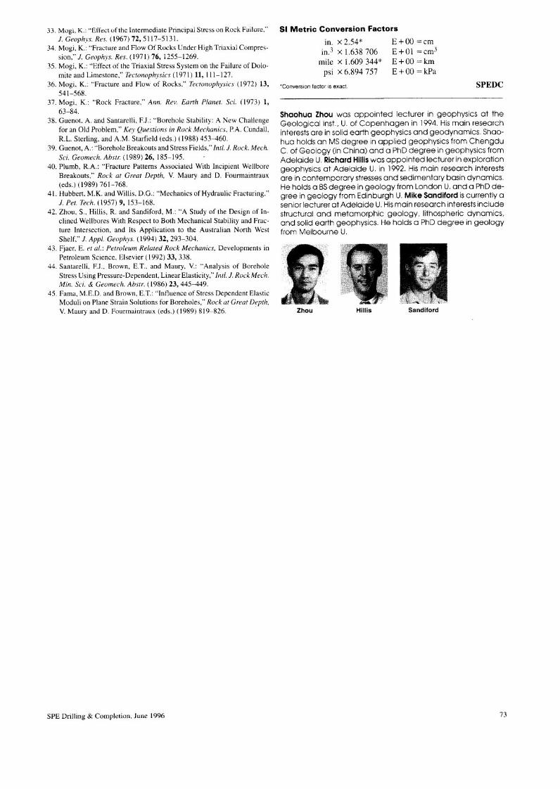
Shaohua Zhou was appointed lecturer in geophysics at theGeological Inst., U. of Copenhagen in 1994. Hismain researchinterests are in solid earth geophysics and geodynamics. Shao-hua holds an MS degree in applied geophysics from ChengduC. of Geology (in China) and a PhD degree in geophysics fromAdelaide U. Richard Hilliswas appointed lecturer in explorationgeophysics at Adelaide U. in 1992. Hismain research interestsare in contemporary stressesand sedimentary basin dynamics.He holds a BSdegree in geology from London U. and a PhD de-gree in geology from Edinburgh U. Mike Sandiford iscurrently asenior lecturer at Adelaide U.Hismain research interests includestructural and metamorphic geology, Iithospheric dynamics,and solid earth geophysics. He holds a PhD degree in geologyfrom Melbourne U.
SandifordZhou
73


![Thermal and mechanical stability of wurtzite-ZrA1N/cubic-TiN ...liu.diva-portal.org/smash/get/diva2:1136722/FULLTEXT01.pdfimprove the thermal stability [21-23], mechanical properties](https://img.pdfslide.net/doc/110x75/60cb6e32a777527c4275fe9b/thermal-and-mechanical-stability-of-wurtzite-zra1ncubic-tin-liudiva-1136722fulltext01pdf.jpg)