Embed Size (px)
Citation preview
MR40CH02-Ritchie ARI 3 June 2010 23:9
On the Mechanistic Originsof Toughness in BoneMaximilien E. Launey,1 Markus J. Buehler,2
and Robert O. Ritchie1,3
1Materials Sciences Division, Lawrence Berkeley National Laboratory, Berkeley,California 94720; email: [email protected], [email protected] of Civil and Environmental Engineering, Massachusetts Institute of Technology,Cambridge, Massachusetts 02139; email: [email protected] of Materials Science and Engineering, University of California, Berkeley,California 94720
Annu. Rev. Mater. Res. 2010. 40:25–53
First published online as a Review in Advance onFebruary 26, 2010
The Annual Review of Materials Research is online atmatsci.annualreviews.org
This article’s doi:10.1146/annurev-matsci-070909-104427
Copyright c© 2010 by Annual Reviews.All rights reserved
1531-7331/10/0804-0025$20.00
Key Words
fracture, deformation, mechanisms, length scales
Abstract
One of the most intriguing protein materials found in nature is bone, amaterial composed of assemblies of tropocollagen molecules and tiny hy-droxyapatite mineral crystals that form an extremely tough, yet lightweight,adaptive and multifunctional material. Bone has evolved to provide structuralsupport to organisms, and therefore its mechanical properties are of greatphysiological relevance. In this article, we review the structure and propertiesof bone, focusing on mechanical deformation and fracture behavior from theperspective of the multidimensional hierarchical nature of its structure. Infact, bone derives its resistance to fracture with a multitude of deformationand toughening mechanisms at many size scales ranging from the nanoscalestructure of its protein molecules to the macroscopic physiological scale.
25
Ann
u. R
ev. M
ater
. Res
. 201
0.40
:25-
53. D
ownl
oade
d fr
om a
rjou
rnal
s.an
nual
revi
ews.
org
by M
ASS
AC
HU
SET
TS
INST
ITU
TE
OF
TE
CH
NO
LO
GY
on
08/2
4/10
. For
per
sona
l use
onl
y.
MR40CH02-Ritchie ARI 3 June 2010 23:9
1. INTRODUCTION
By manipulating combinations of minerals and organic polymers into hierarchical structures span-ning multiple length scales, nature has developed a wide range of hybrid materials with specificproperties matched to function (1–4). Indeed, these biological systems represent an inexhaustiblesource of inspiration to materials scientists in offering potential solutions for the development ofnew generations of structural materials (5–7). Nature’s key role here is in the complex hierarchicalstructuring of the materials (8–12) that, unlike engineering materials that are fabricated accordingto specific requirements, are grown using the principles of biologically controlled self-assembly(2). The act of growing rather than fabricating leads to the possibility of dynamic strategy, whichallows for flexibility at all levels. The concept of multiscale hierarchical structures, where the mi-crostructure at each level is adapted to local needs (13), allows for the adaptation and optimizationof a material’s form and structure at each level of hierarchy to meet specific functions (11, 12, 14).Indeed, the complexity and symbiosis of structural biological materials have generated enormousinterest of late, primarily because these composite biological systems exhibit mechanical propertiesthat are invariably far superior to those of their individual constituents (15).
One of the most intriguing and complex materials found in nature is bone. Like any otherbiological systems, bone is a highly hierarchical composite material composed primarily of as-semblies of collagenous protein molecules, water, and mineral nanoparticles made of carbonatedhydroxyapatite, forming an extremely tough, lightweight, adaptive, and multifunctional material.Bone is often stereotyped as simply a protective and supportive framework for the body; althoughit does perform this function, it is actually a very dynamic organ that is constantly remodelingand changing shape to adapt to the daily forces placed upon it. Like all natural materials, itsmechanical properties are determined by its structure (2, 15, 16), which in turn is motivated byits (primarily mechanical) function (17, 18). The adaptation of compact bone to its mechanicalenvironment includes both alteration of its shape and adaptation of its internal structure, i.e., itsmaterial properties. Long bones, such as the femur and the tibia, provide stability against bendingand buckling. Short bones, e.g., vertebrae, provide stability against compression, whereas plate-like bones such as those forming the skull protect vital organs. The diversity of structures withinthis family reflects the fine-tuning or adaptation of the structure to its function.
In addition, a remarkable property of bone is its well-known capacity of self-repair (19). Inbone, the combination of growth and remodeling (resorption and replacement of old material)occurs via specialized cells (osteoclasts) that are permanently removing material while other cells(osteoblasts) are depositing new tissue. This continuous remodeling allows for structural adapta-tion to changing external conditions, as well as the removal and replacement of damaged material(16, 20, 21). Unfortunately, excessive remodeling and other aging-related changes to the mus-culoskeletal system increase susceptibility to bone fracture (22). In the case of the elderly, suchchanges are critical because the consequent fractures can lead to significant mortality. Although anumber of extraosseous variables, such as loading regime, incidence of traumatic falls, and priorfractures, are involved, the bone tissue itself deteriorates with age (22–24). A primary factor hereis bone quality, which is a loosely defined term used to describe some, but probably not all, char-acteristics of the bone matrix nano- and microstructure that can influence mechanical propertiessuch as stiffness (resistance to elastic deformation), strength (resistance to plastic deformation),and toughness (resistance to fracture).
Traditional thinking on the deterioration of bone with age has focused on bone quantity as apredictor of such fracture risk. Bone quantity is described by the bone mass or bone mineral density(BMD), defined as the amount of bone mineral per unit cross-sectional area. For example, theelevation in bone-remodeling activity, concurrent with menopause in aging women, can lead to
26 Launey · Buehler · Ritchie
Ann
u. R
ev. M
ater
. Res
. 201
0.40
:25-
53. D
ownl
oade
d fr
om a
rjou
rnal
s.an
nual
revi
ews.
org
by M
ASS
AC
HU
SET
TS
INST
ITU
TE
OF
TE
CH
NO
LO
GY
on
08/2
4/10
. For
per
sona
l use
onl
y.
MR40CH02-Ritchie ARI 3 June 2010 23:9
osteoporosis, a condition of low bone mass associated with an increased risk of fracture. However,although bone mass can explain some of the fracture risk, there is now mounting evidence thatlow BMD alone is not the sole factor responsible for the aging-induced fracture risk. Specifically,a landmark study by Hui et al. (22) revealed a roughly tenfold increase in fracture risk with agingthat was independent of BMD. This result and the concurrent realization that bone mass alonecannot explain the therapeutic benefits of antiresorptive agents in treating osteoporosis (24) havereemphasized the necessity for understanding the factors that control bone quality. Indeed, therehas recently been a renewed interest in the strength and fracture properties of bone, motivatedby the notion that an appropriate assessment of bone quality could potentially be used to predictthe risk of bone fracture.
As there is still only limited understanding of the physics-based mechanisms of bone fractureand how they relate to its hierarchical, multidimensional structure (25, 26), one vital questionthat is paramount is the origin of bone’s fracture resistance in relation to these structural lengthscales. To understand the toughness of bone and to discern the roles of the observed tougheningmechanisms, it is pertinent to note that fracture resistance is a multiple-scale process, with eachlevel of structural hierarchy adapted to provide optimal toughness. Traditionally, toughness hasbeen thought of as the ability of a material to dissipate deformation energy without propagationof a crack. However, fracture is actually the result of a mutual competition of (a) intrinsic damagemechanisms ahead of a crack tip that promote cracking and (b) extrinsic shielding mechanisms,mainly behind the tip, that impede cracking (27, 28). Intrinsic toughening mechanisms increasethe microstructural resistance to crack initiation and growth, as exemplified by the role of plasticityahead of the crack tip in metals. Extrinsic toughening involves microstructural mechanisms thatact primarily behind the crack tip to inhibit crack growth by effectively reducing the crack-drivingforce actually experienced at the crack tip, as illustrated by crack-tip shielding mechanisms such ascrack bridging (29, 30). A discussion on how the fracture toughness can be quantitatively measuredin light of these different classes of mechanisms is presented in the Appendix.
In this review, we describe the mechanistic roles that the multilevel structural constituents ofbone play in affecting its resistance to fracture, in terms of both the initiation and the subsequentpropagation of cracks. We show that the toughness of bone is a result of a suite of potent extrinsic(shielding) mechanisms, specifically crack deflection and bridging, acting primarily at the microlength scales and above (typically at dimensions above ∼1 μm) (31), coupled with an additionalrole of intrinsic toughening due to the significant plasticity in the material generated at multiplelength scales (although primarily at dimensions below ∼1 μm). Whereas the extrinsic shieldingmechanisms affect only the propagation of cracks (as assessed by the crack-resistance curve, orR-curve), the plasticity mechanisms in bone affect both crack initiation and growth and include anumber of inelastic, nonrecoverable deformation mechanisms, such as local collagen fibrillar shear-ing and viscoplasticity at submicrometer scales and microcracking at somewhat coarser scales (32).
2. HIERARCHICAL STRUCTURE OF BONE
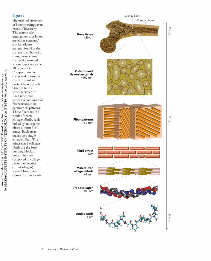
The structure of bone can be viewed as cascaded arrangements of building blocks at defined lengthscales (Figure 1). These building blocks form a hierarchical structure that controls its properties,e.g., deformation and toughness (25, 26, 33). Bone tissue can be either trabecular (spongy) orcortical (compact). Trabecular bone, also known as cancellous bone, fills the insides of manybones; it is spongy with struts of order 100–300 μm in diameter. This review focuses primarilyon cortical bone, which is the dense bone that is found at the outer surfaces of all bones. Thecortical bone shell can reach a thickness of between several tenths of a millimeter (in vertebrae)and several millimeters (in the mid-shaft of long bones). Structurally, the basic building blocks
www.annualreviews.org • On the Mechanistic Origins of Toughness in Bone 27
Ann
u. R
ev. M
ater
. Res
. 201
0.40
:25-
53. D
ownl
oade
d fr
om a
rjou
rnal
s.an
nual
revi
ews.
org
by M
ASS
AC
HU
SET
TS
INST
ITU
TE
OF
TE
CH
NO
LO
GY
on
08/2
4/10
. For
per
sona
l use
onl
y.
MR40CH02-Ritchie ARI 3 June 2010 23:9
Ma
croN
an
oM
icro
Amino acids~1 nm
Tropocollagen~300 nm
Mineralizedcollagen fibrils
~1 mm
Fibril arrays~10 mm
Fiber patterns~50 mm
Osteons and Haversian canals
~100 mm
Bone tissue~50 cm
Compact bone
Spongy boneFigure 1Hierarchical structureof bone showing sevenlevels of hierarchy.The macroscalearrangements of bonesare either compact/cortical (densematerial found at thesurface of all bones) orspongy/cancellous(foam-like materialwhose struts are some100 μm thick).Compact bone iscomposed of osteonsthat surround andprotect blood vessels.Osteons have alamellar structure.Each individuallamella is composed offibers arranged ingeometrical patterns.These fibers are theresult of severalcollagen fibrils, eachlinked by an organicphase to form fibrilarrays. Each arraymakes up a singlecollagen fiber. Themineralized collagenfibrils are the basicbuilding blocks ofbone. They arecomposed of collagenprotein molecules(tropocollagen)formed from threechains of amino acids.
28 Launey · Buehler · Ritchie
Ann
u. R
ev. M
ater
. Res
. 201
0.40
:25-
53. D
ownl
oade
d fr
om a
rjou
rnal
s.an
nual
revi
ews.
org
by M
ASS
AC
HU
SET
TS
INST
ITU
TE
OF
TE
CH
NO
LO
GY
on
08/2
4/10
. For
per
sona
l use
onl
y.
MR40CH02-Ritchie ARI 3 June 2010 23:9
of such bone are an organic matrix (90% type I collagen, 10% amorphous ground substance)and a mineral phase (calcium phosphate–based hydroxyapatite). However, bone composition andstructure are not invariant; they vary with factors such as skeletal site, age, sex, physiologicalfunction, and mechanical loading, making bone a very heterogeneous structure. Different bonesgrow at different rates, and the kind of primary bone laid down depends on the rate of accretion.The mineral content varies substantially from bone to bone; antlers have the lowest mineralcontent in the bone family (55–60 wt%), and whale fins have the highest mineral content (∼90%wt%) (16). The main determinant of mechanical properties is generally the amount of mineral inthe tissue (16, 18). Accordingly, different bones have different mechanical properties depending onthe growth, structure, and adaptation, all of which are interconnected to serve a specific function.
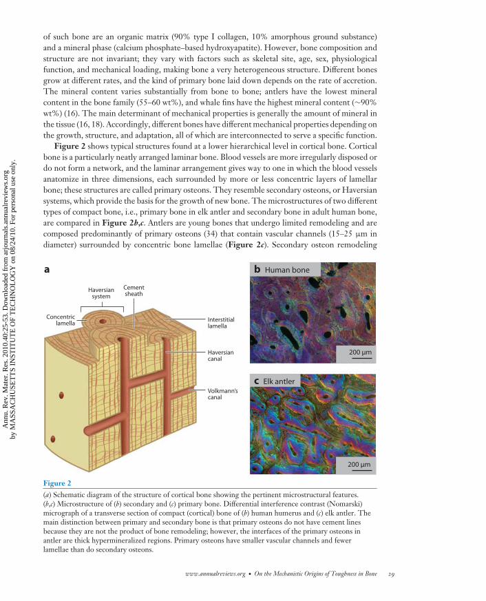
Figure 2 shows typical structures found at a lower hierarchical level in cortical bone. Corticalbone is a particularly neatly arranged laminar bone. Blood vessels are more irregularly disposed ordo not form a network, and the laminar arrangement gives way to one in which the blood vesselsanatomize in three dimensions, each surrounded by more or less concentric layers of lamellarbone; these structures are called primary osteons. They resemble secondary osteons, or Haversiansystems, which provide the basis for the growth of new bone. The microstructures of two differenttypes of compact bone, i.e., primary bone in elk antler and secondary bone in adult human bone,are compared in Figure 2b,c. Antlers are young bones that undergo limited remodeling and arecomposed predominantly of primary osteons (34) that contain vascular channels (15–25 μm indiameter) surrounded by concentric bone lamellae (Figure 2c). Secondary osteon remodeling
Haversiansystem
Cementsheath
Concentriclamella
Interstitiallamella
Haversiancanal
Volkmann’scanal
b Human bone
c Elk antler
200 μm
200 μm
a
Figure 2(a) Schematic diagram of the structure of cortical bone showing the pertinent microstructural features.(b,c) Microstructure of (b) secondary and (c) primary bone. Differential interference contrast (Nomarski)micrograph of a transverse section of compact (cortical) bone of (b) human humerus and (c) elk antler. Themain distinction between primary and secondary bone is that primary osteons do not have cement linesbecause they are not the product of bone remodeling; however, the interfaces of the primary osteons inantler are thick hypermineralized regions. Primary osteons have smaller vascular channels and fewerlamellae than do secondary osteons.
www.annualreviews.org • On the Mechanistic Origins of Toughness in Bone 29
Ann
u. R
ev. M
ater
. Res
. 201
0.40
:25-
53. D
ownl
oade
d fr
om a
rjou
rnal
s.an
nual
revi
ews.
org
by M
ASS
AC
HU
SET
TS
INST
ITU
TE
OF
TE
CH
NO
LO
GY
on
08/2
4/10
. For
per
sona
l use
onl
y.
MR40CH02-Ritchie ARI 3 June 2010 23:9
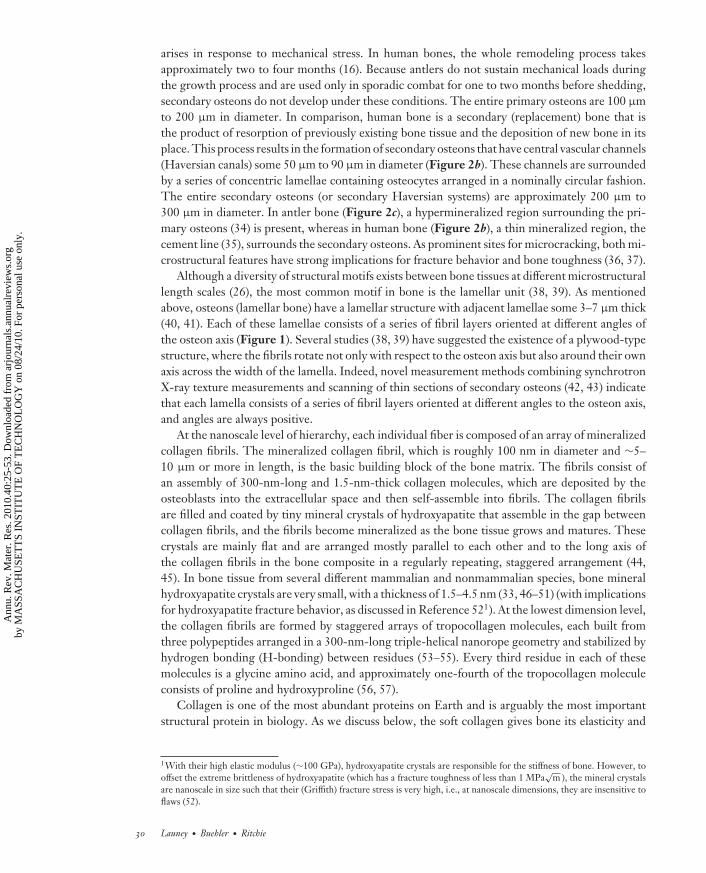
arises in response to mechanical stress. In human bones, the whole remodeling process takesapproximately two to four months (16). Because antlers do not sustain mechanical loads duringthe growth process and are used only in sporadic combat for one to two months before shedding,secondary osteons do not develop under these conditions. The entire primary osteons are 100 μmto 200 μm in diameter. In comparison, human bone is a secondary (replacement) bone that isthe product of resorption of previously existing bone tissue and the deposition of new bone in itsplace. This process results in the formation of secondary osteons that have central vascular channels(Haversian canals) some 50 μm to 90 μm in diameter (Figure 2b). These channels are surroundedby a series of concentric lamellae containing osteocytes arranged in a nominally circular fashion.The entire secondary osteons (or secondary Haversian systems) are approximately 200 μm to300 μm in diameter. In antler bone (Figure 2c), a hypermineralized region surrounding the pri-mary osteons (34) is present, whereas in human bone (Figure 2b), a thin mineralized region, thecement line (35), surrounds the secondary osteons. As prominent sites for microcracking, both mi-crostructural features have strong implications for fracture behavior and bone toughness (36, 37).
Although a diversity of structural motifs exists between bone tissues at different microstructurallength scales (26), the most common motif in bone is the lamellar unit (38, 39). As mentionedabove, osteons (lamellar bone) have a lamellar structure with adjacent lamellae some 3–7 μm thick(40, 41). Each of these lamellae consists of a series of fibril layers oriented at different angles ofthe osteon axis (Figure 1). Several studies (38, 39) have suggested the existence of a plywood-typestructure, where the fibrils rotate not only with respect to the osteon axis but also around their ownaxis across the width of the lamella. Indeed, novel measurement methods combining synchrotronX-ray texture measurements and scanning of thin sections of secondary osteons (42, 43) indicatethat each lamella consists of a series of fibril layers oriented at different angles to the osteon axis,and angles are always positive.
At the nanoscale level of hierarchy, each individual fiber is composed of an array of mineralizedcollagen fibrils. The mineralized collagen fibril, which is roughly 100 nm in diameter and ∼5–10 μm or more in length, is the basic building block of the bone matrix. The fibrils consist ofan assembly of 300-nm-long and 1.5-nm-thick collagen molecules, which are deposited by theosteoblasts into the extracellular space and then self-assemble into fibrils. The collagen fibrilsare filled and coated by tiny mineral crystals of hydroxyapatite that assemble in the gap betweencollagen fibrils, and the fibrils become mineralized as the bone tissue grows and matures. Thesecrystals are mainly flat and are arranged mostly parallel to each other and to the long axis ofthe collagen fibrils in the bone composite in a regularly repeating, staggered arrangement (44,45). In bone tissue from several different mammalian and nonmammalian species, bone mineralhydroxyapatite crystals are very small, with a thickness of 1.5–4.5 nm (33, 46–51) (with implicationsfor hydroxyapatite fracture behavior, as discussed in Reference 521). At the lowest dimension level,the collagen fibrils are formed by staggered arrays of tropocollagen molecules, each built fromthree polypeptides arranged in a 300-nm-long triple-helical nanorope geometry and stabilized byhydrogen bonding (H-bonding) between residues (53–55). Every third residue in each of thesemolecules is a glycine amino acid, and approximately one-fourth of the tropocollagen moleculeconsists of proline and hydroxyproline (56, 57).
Collagen is one of the most abundant proteins on Earth and is arguably the most importantstructural protein in biology. As we discuss below, the soft collagen gives bone its elasticity and
1With their high elastic modulus (∼100 GPa), hydroxyapatite crystals are responsible for the stiffness of bone. However, tooffset the extreme brittleness of hydroxyapatite (which has a fracture toughness of less than 1 MPa
√m ), the mineral crystals
are nanoscale in size such that their (Griffith) fracture stress is very high, i.e., at nanoscale dimensions, they are insensitive toflaws (52).
30 Launey · Buehler · Ritchie
Ann
u. R
ev. M
ater
. Res
. 201
0.40
:25-
53. D
ownl
oade
d fr
om a
rjou
rnal
s.an
nual
revi
ews.
org
by M
ASS
AC
HU
SET
TS
INST
ITU
TE
OF
TE
CH
NO
LO
GY
on
08/2
4/10
. For
per
sona
l use
onl
y.
MR40CH02-Ritchie ARI 3 June 2010 23:9
the ability to dissipate energy under mechanical deformation. Notably, even minute structuralchanges in a collagen molecule’s architecture can have severe consequences for macroscale tissuebehavior, as is evident in genetic bone diseases.
3. INTRINSIC TOUGHENING (DEFORMATION) MECHANISMS
The mechanical properties of the constituents of bone largely control its strength and plasticity.However, these properties are strongly dependent on the scale of observation. Recent experimentaland theoretical studies have provided new insight into the mechanisms underlying this behavior,most notably through the use of advanced instrumentation that has permitted the examination ofbone properties at ever-decreasing length scales, e.g., transmission electron and X-ray microscopy,atomic force microscopy, and Raman spectroscopy, as well as bottom-up multiscale simulationmodeling. Together, these studies suggest that permanent deformation (plasticity) in bone is theresult of concurrent multiple deformation mechanisms that are active predominantly at submi-crometer levels (Figure 3). However, even though individual mechanisms have been identified,there is still no integrated model of plastic deformation in bone. Plasticity at molecular scales isparticularly challenging to identify. Whereas it has been shown that the breaking of H-bonds is acrucial mechanism of large and permanent deformation of protein molecules, fibrils, and fibers,this mechanism is reversible when applied forces are removed (see Figure 4 for an illustrationof how H-bonds break as forces are applied to a collagen protein molecule). The force requiredto break these bonds is highly dependent on the deformation rate (timescales), which provides amechanism to dissipate energy under rapid loading (58–60). Indeed, such breaking of H-bondscan be regarded as a viscoelastic effect. This suggests that plastic deformation in bone must alsoinvolve larger-scale mechanisms such as intermolecular sliding, which would not be reversibleunless remodeling of bone occurred. In general, the salient deformation mechanisms in bone areassociated with different structural levels (Figure 3), as described below.
3.1. Hydrogen-Bond Breakage in Pure Collagen: Molecular Uncoiling
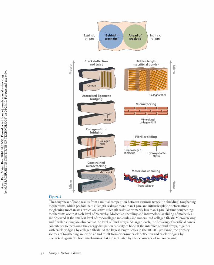
The basic deformation mechanism of individual collagen molecules is molecular stretching andunwinding due first to entropic and then to energetic mechanisms that involve breaking of H-bonds (Figure 4). In collagen fibrils, molecular stretching competes with intermolecular slidingand breaking of weak and strong bonds between tropocollagen molecules. These sliding motionsprovide the basis for large plastic strains without catastrophic brittle failure. Severe mechanicaltensile loading of collagen is significant under physiological conditions in various related tissues,representing one of its key performance features, as shown by its ability to stretch up to 50% tensilestrain before breaking while reaching force levels of more than 10 nN (per molecule) or 10–20 GPastress (obtained by normalization of the force by the cross-sectional area of the molecule) (61–65). Figure 5 shows a tensile test of a tropocollagen molecule for deformation up to 40% strain.The plot also shows the progression of H-bond breaking as the molecule unravels (65). H-bondbreakage at 10% to 20% strain provides one of the major mechanisms that mediate the deformationof collagen fibrils; it is a reversible process and may thus provide a means to dissipate energythrough large-deformation behavior of the soft-collagen bone matrix. The specific structure ofintermolecular cross-links thereby plays a crucial role in defining the particular deformation paths.Aged collagen tends to show a high cross-link density, whereas young collagen features few cross-links. The larger the cross-link density, the lower is the material’s ability to dissipate energywithout failure. At large cross-link densities, collagen fibrils tend to involve molecular fractureand breaking of cross-links (66), leading to increasingly brittle material behavior. This is certainlyone factor associated with the increased fracture risk in older bone.
www.annualreviews.org • On the Mechanistic Origins of Toughness in Bone 31
Ann
u. R
ev. M
ater
. Res
. 201
0.40
:25-
53. D
ownl
oade
d fr
om a
rjou
rnal
s.an
nual
revi
ews.
org
by M
ASS
AC
HU
SET
TS
INST
ITU
TE
OF
TE
CH
NO
LO
GY
on
08/2
4/10
. For
per
sona
l use
onl
y.
MR40CH02-Ritchie ARI 3 June 2010 23:9
Extrinsic>1 μm
Intrinsic<1 μm
Ahead of crack tip
Behind crack tip
Osteon
Crack deflectionand twist
Uncracked-ligamentbridging
Constrainedmicrocracking
Collagen-fibrilbridging
Microcracks
Collagenfiber
Bridge
Hidden length(sacrificial bonds)
Microcracking
Fibrillar sliding
Molecular uncoiling
Collagen fiber
Tropocollagen
Mineralizedcollagen fibril
Ma
cro
Mic
ro
Micro
Na
no
Tropocollagenmolecule Hydroxyapatite
crystal
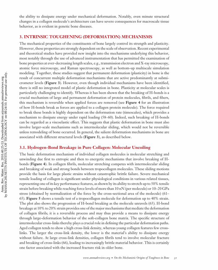
Figure 3The toughness of bone results from a mutual competition between extrinsic (crack-tip shielding) tougheningmechanisms, which predominate at length scales at more than 1 μm, and intrinsic (plastic deformation)toughening mechanisms, which are active at length scales at primarily less than 1 μm. Distinct tougheningmechanisms occur at each level of hierarchy. Molecular uncoiling and intermolecular sliding of moleculesare observed at the smallest level of tropocollagen molecules and mineralized collagen fibrils. Microcrackingand fibrillar sliding are observed at the level of fibril arrays. At larger levels, the breaking of sacrificial bondscontributes to increasing the energy dissipation capacity of bone at the interface of fibril arrays, togetherwith crack bridging by collagen fibrils. At the largest length scales in the 10–100-μm range, the primarysources of toughening are extrinsic and result from extensive crack deflection and crack bridging byuncracked ligaments, both mechanisms that are motivated by the occurrence of microcracking.
32 Launey · Buehler · Ritchie
Ann
u. R
ev. M
ater
. Res
. 201
0.40
:25-
53. D
ownl
oade
d fr
om a
rjou
rnal
s.an
nual
revi
ews.
org
by M
ASS
AC
HU
SET
TS
INST
ITU
TE
OF
TE
CH
NO
LO
GY
on
08/2
4/10
. For
per
sona
l use
onl
y.
MR40CH02-Ritchie ARI 3 June 2010 23:9
0
3,000
6,000
9,000
12,000
15,000
18,000
0% 10% 20% 30% 40%
Strain
Fo
rce
(p
N)
a
b
Molecularrotation
H-bondbreaking
Backbonestretching
0
10
20
30
40
50
60
Nu
mb
er o
f H-b
on
ds
H-bond
Figure 4Structure and nanomechanics of a triple-helical tropocollagen molecule, the basic protein building block ofbone (65, 67). (a) The structure of this protein molecule. The hydrogen-bond (H-bond) structure ( yellow,thick, dashed lines) is depicted at the bottom right. (b) The force-extension behavior, here shown up to 40%strain. Panel b also shows the number of H-bonds (for a tropocollagen segment that is 30 amino acids long).During the first stage of deformation (less than 10% strain), the number of H-bonds remains close to 30,corresponding to approximately one H-bond for each amino acid triplet. When tropocollagen isstraightened, H-bonds gradually break until 25% tensile strain is reached. At this point, a stationary situationis attained, with the number of intramolecular H-bonds close to 15. Beyond this point, the force increase isdue to backbone stretching, and no additional H-bonds break. In this regime, no pattern for the remainingH-bonds can be recognized; H-bonds are continuously broken and reformed along the peptide due to thefact that, even if the triple-helical coiling is lost, the three chains are near enough to form H-bonds.
3.2. Fibrillar Sliding of Mineralized Collagen Fibrils
The mineralized collagen fibrils are of particular significance for bone, as they are its nanostruc-tural building blocks. Because the mineral phase has an elastic modulus that is more than an orderof magnitude higher than that of collagen, the presence of the hydroxyapatite phase is critical tothe stiffness of bone. Indeed, experimental results show a continuous increase in Young’s modulus
www.annualreviews.org • On the Mechanistic Origins of Toughness in Bone 33
Ann
u. R
ev. M
ater
. Res
. 201
0.40
:25-
53. D
ownl
oade
d fr
om a
rjou
rnal
s.an
nual
revi
ews.
org
by M
ASS
AC
HU
SET
TS
INST
ITU
TE
OF
TE
CH
NO
LO
GY
on
08/2
4/10
. For
per
sona
l use
onl
y.
MR40CH02-Ritchie ARI 3 June 2010 23:9
0.00
0.10
0.20
0.30
0.40
0.50
0.60
Engineering strain
Str
ess
(G
Pa
)
a
0.0 0.1 0.2 0.3 0.4 0.5
Pure-collagen fibril
Mineralized collagen fibril
b c
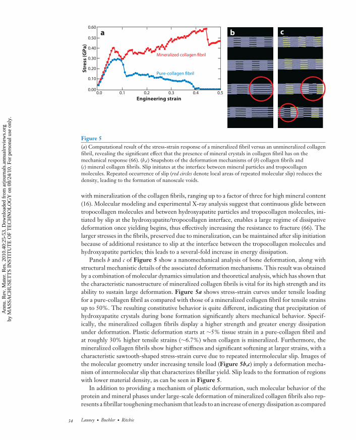
Figure 5(a) Computational result of the stress-strain response of a mineralized fibril versus an unmineralized collagenfibril, revealing the significant effect that the presence of mineral crystals in collagen fibril has on themechanical response (66). (b,c) Snapshots of the deformation mechanisms of (b) collagen fibrils and(c) mineral collagen fibrils. Slip initiates at the interface between mineral particles and tropocollagenmolecules. Repeated occurrence of slip (red circles denote local areas of repeated molecular slip) reduces thedensity, leading to the formation of nanoscale voids.
with mineralization of the collagen fibrils, ranging up to a factor of three for high mineral content(16). Molecular modeling and experimental X-ray analysis suggest that continuous glide betweentropocollagen molecules and between hydroxyapatite particles and tropocollagen molecules, ini-tiated by slip at the hydroxyapatite/tropocollagen interface, enables a large regime of dissipativedeformation once yielding begins, thus effectively increasing the resistance to fracture (66). Thelarger stresses in the fibrils, preserved due to mineralization, can be maintained after slip initiationbecause of additional resistance to slip at the interface between the tropocollagen molecules andhydroxyapatite particles; this leads to a several-fold increase in energy dissipation.
Panels b and c of Figure 5 show a nanomechanical analysis of bone deformation, along withstructural mechanistic details of the associated deformation mechanisms. This result was obtainedby a combination of molecular dynamics simulation and theoretical analysis, which has shown thatthe characteristic nanostructure of mineralized collagen fibrils is vital for its high strength and itsability to sustain large deformation. Figure 5a shows stress-strain curves under tensile loadingfor a pure-collagen fibril as compared with those of a mineralized collagen fibril for tensile strainsup to 50%. The resulting constitutive behavior is quite different, indicating that precipitation ofhydroxyapatite crystals during bone formation significantly alters mechanical behavior. Specif-ically, the mineralized collagen fibrils display a higher strength and greater energy dissipationunder deformation. Plastic deformation starts at ∼5% tissue strain in a pure-collagen fibril andat roughly 30% higher tensile strains (∼6.7%) when collagen is mineralized. Furthermore, themineralized collagen fibrils show higher stiffness and significant softening at larger strains, with acharacteristic sawtooth-shaped stress-strain curve due to repeated intermolecular slip. Images ofthe molecular geometry under increasing tensile load (Figure 5b,c) imply a deformation mecha-nism of intermolecular slip that characterizes fibrillar yield. Slip leads to the formation of regionswith lower material density, as can be seen in Figure 5.
In addition to providing a mechanism of plastic deformation, such molecular behavior of theprotein and mineral phases under large-scale deformation of mineralized collagen fibrils also rep-resents a fibrillar toughening mechanism that leads to an increase of energy dissipation as compared
34 Launey · Buehler · Ritchie
Ann
u. R
ev. M
ater
. Res
. 201
0.40
:25-
53. D
ownl
oade
d fr
om a
rjou
rnal
s.an
nual
revi
ews.
org
by M
ASS
AC
HU
SET
TS
INST
ITU
TE
OF
TE
CH
NO
LO
GY
on
08/2
4/10
. For
per
sona
l use
onl
y.
MR40CH02-Ritchie ARI 3 June 2010 23:9
with fibrils without a mineral phase (66, 67). This is an intrinsic toughening mechanism (Figure 3)that enhances the resistance to fracture by forming larger, local yield regions around crack-likedefects, a mechanism that protects the integrity of the entire structure by allowing for localizedfailure. As a consequence, mineralized collagen fibrils are able to tolerate microcracks on the orderof several hundred micrometers in size without causing any macroscopic failure of the tissue.
Specifically, the inclusion of the nanoscale mineral platelets on collagen fibrils increases notonly their Young’s modulus but also their yield and fracture strengths. In terms of numbers, theYoung’s modulus, tensile yield strain, and fracture strength for mineralized collagen fibrils are6.2 GPa, 6.7%, and 0.6 GPa, respectively, as compared with the corresponding values of 4.6 GPa,5%, and 0.3 GPa, respectively, for pure-collagen fibrils.
3.3. Fibrillar Sliding of Collagen Fiber Arrays
The long (>5–10-μm) and thin (∼100-nm) mineralized collagen fibrils are twisted into collagenfibers, which are “glued” together by a thin layer (1–2 nm thick) of extrafibrillar matrix (68, 69).When the tissue is externally loaded in tension, the load is resolved into tensile deformation of themineralized fibrils and shearing deformation in the extrafibrillar matrix (70). Although no precisedata on its mechanical behavior or its composition are available, it is likely that the extrafibrillarmatrix is composed of noncollagenous proteins, such as osteopontin, and proteoglycans, such asdecorin. Indeed, single-molecule spectroscopy of fractured bone surfaces has confirmed that theextrafibrillar matrix has properties similar to those of a glue layer between the fibrils—it is relativelyweak but ductile and deforms by the successive breaking of a series of sacrificial bonds (68, 71).Specifically, the separation of individual fibrils and the larger fibers during deformation and frac-ture is resisted by this macromolecular glue via sacrificial bonds that break at a fraction (∼0.1–0.5)of the force required to break the backbone of the macromolecules (72). The matrix may also bepartially calcified (73), which would increase its shear stiffness and reduce its deformability. Theseresults point toward a deformation mechanism whereby the matrix/fiber interface is disrupted be-yond the yield point, and the matrix moves past the fibers forming and reforming the matrix/fiberbonds. An alternative explanation involves the disruption of bonds between the matrix and hy-droxyapatite particles and a modification of the frictional stress between individual fibers (74).
3.4. Microcracking
At several length scales from the submicrometer scale to a scale of tens of micrometers, the processof microcracking in bone provides the prevalent mechanism of microscale deformation (75–78).As described in the next section, not only is such microcracking a process of plastic deforma-tion, thereby providing an intrinsic contribution to the toughness of bone, but it is an essentialphenomenon for the development of the most potent extrinsic toughening mechanisms, notablycrack bridging and crack deflection, that predominate at larger length scales (31). Microcrackingmay also play a crucial role in signaling the remodeling of the bone, which occurs in so-calledbasic multicellular units (BMUs), i.e., combination of cells that are able to remove (osteoclasts)and form (osteoblasts) bone tissue (21).
4. EXTRINSIC TOUGHENING (SHIELDING) MECHANISMS
The (primary) submicrometer deformation mechanisms described above contribute intrinsically tothe fracture toughness of bone by forming plastic zones around crack-like defects, thereby protect-ing the integrity of the entire structure by allowing for localized failure through energy dissipation.However, at micro- to macroscale dimensions, the toughness of cortical bone is associated with a
www.annualreviews.org • On the Mechanistic Origins of Toughness in Bone 35
Ann
u. R
ev. M
ater
. Res
. 201
0.40
:25-
53. D
ownl
oade
d fr
om a
rjou
rnal
s.an
nual
revi
ews.
org
by M
ASS
AC
HU
SET
TS
INST
ITU
TE
OF
TE
CH
NO
LO
GY
on
08/2
4/10
. For
per
sona
l use
onl
y.
MR40CH02-Ritchie ARI 3 June 2010 23:9
very different kind of toughening involving crack-tip shielding (Figure 3). Perhaps surprisingly,the main structural feature that appears to control such extrinsic toughening, namely the osteons,is quite large; osteons are several hundred micrometers in size (79). Akin to many biological mate-rials, these structural features provide a source of toughening that arises during crack growth ratherthan during crack initiation. To better understand this distinction, it is important to consider thatmany of the macroscopic fracture toughness properties of bone can be explained mechanisticallyin terms of the nature of the crack path. A central feature of this fracture behavior is that certainfeatures in the microstructure, especially the interfaces of the osteons, provide microstructurallyweak or preferred paths for cracking. As these features have a specific alignment in bone, theosteons provide the basis for the marked anisotropy of the fracture properties of bone (bone iseasier to split and to break) (31, 37, 80–82) and for the fact that the toughness is actually lower inshear than in tension (80, 83, 84).
4.1. Constrained Microcracking
In cortical bone, the path of least microstructural resistance is invariably along the cement lines (80,83, 84), which are the hypermineralized interfaces between the bone matrix and secondary osteonstructures (e.g., in human bone), or along the similarly hypermineralized boundaries of the primaryosteons (e.g., in antler bone). These regions are therefore preferential sites for major microcracksto form, particularly as bone ages and the osteon density increases with remodeling. These micro-cracks thus have a typical spacing in the tens to hundreds of micrometers and are aligned primarilyalong the long axis of the bone, an orientation that directly results in the strong anisotropy of tough-ness in bone. Fracture of hydroxyapatite crystals surrounding collagen fibers or delamination atthe crystal/fiber interfaces has been suggested as the cause of such microcracking damage (85).
Because such microcrack formation predominates in the vicinity of a growing (macro) crackwhere the local stresses are highest, it had been thought that this process was responsible forthe marked R-curve toughness behavior in bone (75–78). However, recent calculations (83, 87)have clearly shown that, although microcracking is important intrinsically for toughness as adeformation mechanism, its direct extrinsic contribution to toughness is minimal.2 However,the importance of microcracking extrinsically is that it results in both crack bridging and crackdeflection, which are the most potent toughening mechanisms in bone.
4.2. Crack Deflection/Twist and Crack Bridging
The occurrence of microcracking is the source of extrinsic toughening in bone that is associatedprimarily with mechanisms such as crack deflection/twist and crack bridging (31, 37, 80–82).In fracture, crack trajectories result from the competition between the direction of maximummechanical driving force [defined by the maximum strain energy release rate, Gmax, or wherethe mode II (shear) stress intensity is zero, KII = 0] and the path of weakest microstructureresistance (84, 88). Where these two paths conflict, high toughness generally results. In contrastto the longitudinal orientations, where these preferred mechanical and microstructural crack pathsare nominally in the same direction (Figure 6f, j ), these two requirements are incommensurate
2Such a contribution would arise from the creation of a zone of microcracking surrounding the crack where the stresses arehighest. As microcrack formation leads to a dilation in this zone, which is constrained by surrounding regions that are lessmicrocracked, the concept of constrained microcracking involves the advancement of the crack into a zone of compression,thereby inducing extrinsic toughening and R-curve behavior. However, for realistic volume fractions of microcracks in bone,the contribution to the overall toughness from this mechanism has been estimated to be less than 0.1 MPa
√m (83, 87).
36 Launey · Buehler · Ritchie
Ann
u. R
ev. M
ater
. Res
. 201
0.40
:25-
53. D
ownl
oade
d fr
om a
rjou
rnal
s.an
nual
revi
ews.
org
by M
ASS
AC
HU
SET
TS
INST
ITU
TE
OF
TE
CH
NO
LO
GY
on
08/2
4/10
. For
per
sona
l use
onl
y.
MR40CH02-Ritchie ARI 3 June 2010 23:9
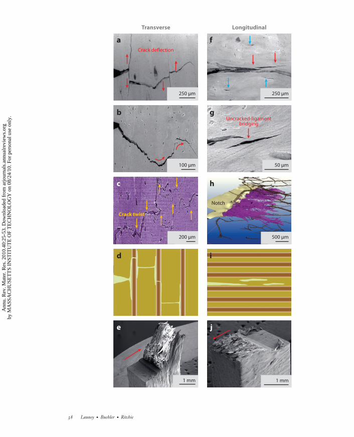
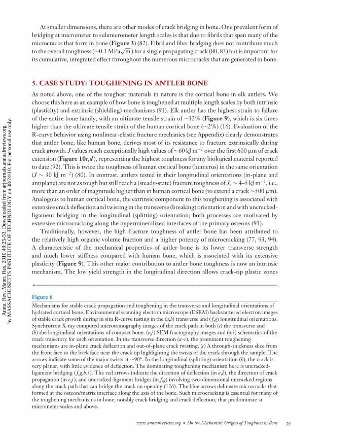
in the transverse (breaking) orientation: The maximum driving force is oriented parallel to anddirectly ahead of the crack tip (which promotes coplanar cracking), and the weakest paths areoriented perpendicular to the crack tip along the direction of the major microcracks (Figure 6a–e). In human cortical bone, because the cement lines are oriented nominally along the longitudinalaxis of the bone, preferred cracking paths tend to be along this direction. Such orientation canlead to the significant (macroscopic) deflection of cracks that are attempting to propagate in thetransverse direction (Figure 6a,e). This phenomenon makes the transverse orientation so muchtougher and makes bone much more difficult to break than to split (80). Recent fracture mechanicsmeasurements show that after only 500 μm of cracking, the fracture toughness, specifically thedriving force for crack propagation, is more than five times higher in the transverse (breaking)direction than in the longitudinal (splitting) direction (Figure 7) (80).
The major distinction in the toughness between these two orientations in bone can be attributeddirectly to the marked difference in crack paths (Figure 6), which in turn results in differenttoughening mechanisms involving primarily crack deflection/twist in the transverse direction andcrack bridging in the longitudinal direction.
4.2.1. Crack deflection/twist. In the transverse orientation, the cement line microcracks arealigned roughly perpendicular to the crack path, where they act as delamination barriers. Thisblunts any growing cracks; causes marked deflections and twists in the crack path (Figure 3); andgenerates highly tortuous crack paths, extremely rough fracture surfaces, and correspondinglyhigh toughness (Figure 6a–e). The latter follows because of the reduced local stress field due tocrack blunting and the need to reinitiate the crack following local arrest at such delaminations. Inaddition, such gross crack-path deviations away from the plane of maximum tensile stress greatlydiminish the local stress intensity at the crack tip, thereby necessitating higher applied loads tocontinue cracking (Figure 7) (80, 83).
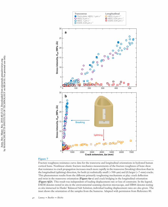
In addition to its important role in human cortical bone, the process of major crack deflec-tions/twists at the osteon boundaries is also a potent source of toughening in the transverseorientation in other forms of bone, particularly in elk antler bone, which is the toughest biologi-cal material on record. Three-dimensional images of crack propagation in antler reveal extensive(out-of-plane) crack twisting at angles of up to ∼90◦ (Figures 6c and 8a,b) in addition to in-planecrack deflections (Figure 8a,b). Linear-elastic calculations using crack-deflection mechanics (89)show that, for in-plane deviations of the crack path, the resulting fracture toughness can be in-creased by up to a factor of two compared with that of an undeflected crack. Where the cracktwists out of plane, this increase can be significantly higher (by a factor of six or more) (90).
4.2.2. Crack bridging. The crack path and consequent salient mechanisms of toughening in thelongitudinal orientations are quite different. In human bone, the cement line microcracks are nowaligned roughly parallel to the growing crack and thus form ahead of, and parallel to, the maincrack tip (termed the “mother and daughter” crack syndrome). The nature of the coalescence ofsuch microcracks to the growing crack leads to the formation of uncracked regions along the cracklength (Figures 6h and 8c,d ) that act to bridge the crack and to carry load that would otherwise beused to further crack propagation (79, 80, 83, 86, 87).3 This mechanism of crack bridging, termeduncracked-ligament bridging, also results in toughening but is a far less potent mechanism thanthat due to crack deflection/twist (31, 80).
3Crack bridging is a common mechanism of extrinsic toughening in many other classes of materials, including the generation ofintact fibers spanning crack paths in many fiber-composite materials, the formation of interlocking grain bridges in monolithicceramics, and ductile-phase bridging in ceramic/metal and ceramic/polymer laminates and composites (29).
www.annualreviews.org • On the Mechanistic Origins of Toughness in Bone 37
Ann
u. R
ev. M
ater
. Res
. 201
0.40
:25-
53. D
ownl
oade
d fr
om a
rjou
rnal
s.an
nual
revi
ews.
org
by M
ASS
AC
HU
SET
TS
INST
ITU
TE
OF
TE
CH
NO
LO
GY
on
08/2
4/10
. For
per
sona
l use
onl
y.
MR40CH02-Ritchie ARI 3 June 2010 23:9
Crack deflection
250 μm
100 μm
200 μm
1 mm 1 mm
250 μm
50 μm
Uncracked-ligamentbridging
500 μm
Notch
a
b
c
d
f
g
h
i
e j
Transverse Longitudinal
Crack twist
38 Launey · Buehler · Ritchie
Ann
u. R
ev. M
ater
. Res
. 201
0.40
:25-
53. D
ownl
oade
d fr
om a
rjou
rnal
s.an
nual
revi
ews.
org
by M
ASS
AC
HU
SET
TS
INST
ITU
TE
OF
TE
CH
NO
LO
GY
on
08/2
4/10
. For
per
sona
l use
onl
y.
MR40CH02-Ritchie ARI 3 June 2010 23:9
At smaller dimensions, there are other modes of crack bridging in bone. One prevalent form ofbridging at micrometer to submicrometer length scales is that due to fibrils that span many of themicrocracks that form in bone (Figure 3) (82). Fibril and fiber bridging does not contribute muchto the overall toughness (∼0.1 MPa
√m ) for a single propagating crack (80, 83) but is important for
its cumulative, integrated effect throughout the numerous microcracks that are generated in bone.
5. CASE STUDY: TOUGHENING IN ANTLER BONE
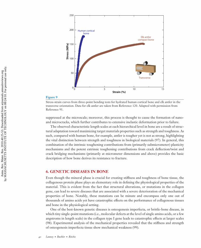
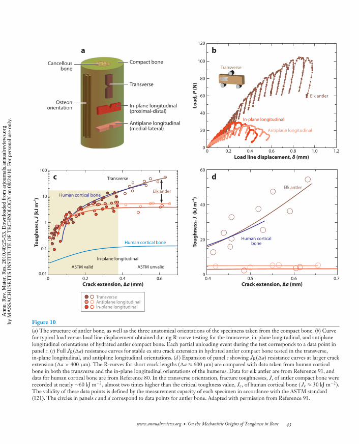
As noted above, one of the toughest materials in nature is the cortical bone in elk antlers. Wechoose this here as an example of how bone is toughened at multiple length scales by both intrinsic(plasticity) and extrinsic (shielding) mechanisms (91). Elk antler has the highest strain to failureof the entire bone family, with an ultimate tensile strain of ∼12% (Figure 9), which is six timeshigher than the ultimate tensile strain of the human cortical bone (∼2%) (16). Evaluation of theR-curve behavior using nonlinear-elastic fracture mechanics (see Appendix) clearly demonstratesthat antler bone, like human bone, derives most of its resistance to fracture extrinsically duringcrack growth. J values reach exceptionally high values of ∼60 kJ m−2 over the first 600 μm of crackextension (Figure 10c,d ), representing the highest toughness for any biological material reportedto date (92). This is twice the toughness of human cortical bone (humerus) in the same orientation(J ∼ 30 kJ m−2) (80). In contrast, antlers tested in their longitudinal orientations (in-plane andantiplane) are not as tough but still reach a (steady-state) fracture toughness of Jc ∼ 4–5 kJ m−2, i.e.,more than an order of magnitude higher than in human cortical bone (to extend a crack ∼500 μm).Analogous to human cortical bone, the extrinsic component to this toughening is associated withextensive crack deflection and twisting in the transverse (breaking) orientation and with uncracked-ligament bridging in the longitudinal (splitting) orientation; both processes are motivated byextensive microcracking along the hypermineralized interfaces of the primary osteons (91).
Traditionally, however, the high fracture toughness of antler bone has been attributed tothe relatively high organic volume fraction and a higher potency of microcracking (77, 93, 94).A characteristic of the mechanical properties of antler bone is its lower transverse strengthand much lower stiffness compared with human bone, which is associated with its extensiveplasticity (Figure 9). This other major contribution to antler bone toughness is now an intrinsicmechanism. The low yield strength in the longitudinal direction allows crack-tip plastic zones
←−−−−−−−−−−−−−−−−−−−−−−−−−−−−−−−−−−−−−−−−−−−−−−−−−−−−−−−−−−−−−−−−−−−−−−−Figure 6Mechanisms for stable crack propagation and toughening in the transverse and longitudinal orientations ofhydrated cortical bone. Environmental scanning electron microscope (ESEM) backscattered electron imagesof stable crack growth during in situ R-curve testing in the (a,b) transverse and ( f,g) longitudinal orientations.Synchrotron X-ray computed microtomography images of the crack path in both (c) the transverse and(h) the longitudinal orientations of compact bone. (e,j ) SEM fractography images and (d,i ) schematics of thecrack trajectory for each orientation. In the transverse direction (a–e), the prominent tougheningmechanisms are in-plane crack deflection and out-of-plane crack twisting. (c) A through-thickness slice fromthe front face to the back face near the crack tip highlighting the twists of the crack through the sample. Thearrows indicate some of the major twists at ∼90◦. In the longitudinal (splitting) orientation (h), the crack isvery planar, with little evidence of deflection. The dominating toughening mechanism here is uncracked-ligament bridging ( f,g,h,i ). The red arrows indicate the direction of deflection (in a,b), the direction of crackpropagation (in e,j ), and uncracked-ligament bridges (in f,g) involving two-dimensional uncracked regionsalong the crack path that can bridge the crack on opening (126). The blue arrows delineate microcracks thatformed at the osteon/matrix interface along the axis of the bone. Such microcracking is essential for many ofthe toughening mechanisms in bone, notably crack bridging and crack deflection, that predominate atmicrometer scales and above.
www.annualreviews.org • On the Mechanistic Origins of Toughness in Bone 39
Ann
u. R
ev. M
ater
. Res
. 201
0.40
:25-
53. D
ownl
oade
d fr
om a
rjou
rnal
s.an
nual
revi
ews.
org
by M
ASS
AC
HU
SET
TS
INST
ITU
TE
OF
TE
CH
NO
LO
GY
on
08/2
4/10
. For
per
sona
l use
onl
y.
MR40CH02-Ritchie ARI 3 June 2010 23:9
0 1000 2000 3000 4000 5000 6000 70000
5
10
15
20
25
30
0 100 200 300 400 5000
5
10
15
20
25
30
Crack extension, Δa (mm)
Str
ess
in
ten
sity
, Ke
ff (
MP
a m
)S
tre
ss i
nte
nsi
ty, K
eff
(M
Pa
m)
a
b
Thick plate, HBSS, 1 μm s–1
HBSS, 6 μm s–1
HBSS, 1 μm s–1
ESEM, 0.04 μm s–1
HBSS, 6 μm s–1
HBSS, 0.04 μm s–1
ESEM, 0.04 μm s–1
Transverse Longitudinal
Breaking
Splitting
Figure 7Fracture toughness resistance curve data for the transverse and longitudinal orientations in hydrated humancortical bone. Nonlinear-elastic fracture mechanics measurements of the fracture toughness of bone showthat resistance to crack propagation increases much more rapidly in the transverse (breaking) direction than inthe longitudinal (splitting) direction, for both (a) realistically small (<500-μm) and (b) larger (<7-mm) cracks.This phenomenon results from the different primarily toughening mechanisms at play: crack deflectionand twist in the transverse orientation (Figure 6a–c) and crack bridging in the longitudinal orientation(Figure 6f,h). This result was independent of loading displacement rate or loss of constraint. In the legend,ESEM denotes tested in situ in the environmental scanning electron microscope, and HBSS denotes testingex situ immersed in Hanks’ Balanced Salt Solution; individual loading displacement rates are also given. Theinset shows the orientation of the samples from the humerus. Adapted with permission from Reference 80.
40 Launey · Buehler · Ritchie
Ann
u. R
ev. M
ater
. Res
. 201
0.40
:25-
53. D
ownl
oade
d fr
om a
rjou
rnal
s.an
nual
revi
ews.
org
by M
ASS
AC
HU
SET
TS
INST
ITU
TE
OF
TE
CH
NO
LO
GY
on
08/2
4/10
. For
per
sona
l use
onl
y.
MR40CH02-Ritchie ARI 3 June 2010 23:9
Haversian canals
Twists anddeflections
Crack
100 μm
Crack
Haversian canals
Twists and deflectionsat cement sheaths
100 μm
Haversian canals
Crack 100 μm
Uncracked-ligamentbridges
Crack
Haversiancanals Uncracked-ligament
bridging at cement sheaths
100 μm
a b
c d
Transverse orientation
Longitudinal orientation
Notch
Notch
Notch
Notch
Back face
Front face
Back face
Front face
Crackdeflection
Cracktwist
Figure 8Three-dimensional reconstructions in the transverse and longitudinal orientations from synchrotron X-raycomputed tomography. Panels a and c show an edge on view of the notch and crack to show the shape of thecrack paths. Panels b and d are oriented to highlight the dominant toughening mechanisms in the twoorientations. The reconstructions show that the principal toughening mechanisms in bone are associatedwith the cement lines (or sheaths). In the transverse direction, crack twist and deflection dominate thetoughness and occur predominantly at the cement sheaths before the crack penetrates the Haversiansystems. Three-dimensional imaging in the longitudinal orientation provides novel insight into how thedominant toughening mechanism of uncracked-ligament bridging is associated with Haversian systems. Asshown in panel d, the crack “flows” around the Haversian system; effectively, the crack does not penetratethe Haversian system but propagates along the surrounding cement sheath, leaving an intact Haversiansystem bridging the crack faces.
to form at lower stresses than in human bone (77, 93), which contributes to the large inelasticdeformation and thereby to the intrinsic toughness of antler bone. Such contributions fromnanoscale plasticity within the mineralized collagen fibrils are important, although little is knownabout these mechanisms in antler. Recently, in situ tensile testing on compact antler bonecombined with small-angle X-ray diffraction measurements (95) has revealed that, although bothantler bone and (bovine) bone show similar nanoscale fibril shearing mechanisms (96) duringelastic deformation, with inelastic deformation, i.e., after macroscopic yielding, the mechanismsare different, with inhomogeneous fibril stretching in antler leading to defects and to consequentdebonding between neighboring fibrils. The result is that strain localization in antler bone is
www.annualreviews.org • On the Mechanistic Origins of Toughness in Bone 41
Ann
u. R
ev. M
ater
. Res
. 201
0.40
:25-
53. D
ownl
oade
d fr
om a
rjou
rnal
s.an
nual
revi
ews.
org
by M
ASS
AC
HU
SET
TS
INST
ITU
TE
OF
TE
CH
NO
LO
GY
on
08/2
4/10
. For
per
sona
l use
onl
y.
MR40CH02-Ritchie ARI 3 June 2010 23:9
0 5 10
50
100
150
200
250
Strain (%)
Str
ess
(M
Pa
)
150
Transverse
Elk antlercompact bone
Human corticalbone
Figure 9Stress-strain curves from three-point bending tests for hydrated human cortical bone and elk antler in thetransverse orientation. Data for elk antler are taken from Reference 120. Adapted with permission fromReference 91.
suppressed at the microscale; moreover, this process is thought to cause the formation of nano-and microcracks, which further contributes to extensive inelastic deformation prior to failure.
The observed characteristic length scales at each hierarchical level in bone are a result of struc-tural adaptation toward maximizing target materials properties such as strength and toughness. Assuch, compared with human bone, for example, antler is tougher yet is not as strong, highlightingthe vital distinction between strength and toughness in biological materials (97). In general, thiscombination of the intrinsic toughening contributions from (primarily submicrometer) plasticitymechanisms and the potent extrinsic toughening contributions from crack deflection/twist andcrack bridging mechanisms (primarily at micrometer dimensions and above) provides the basicdescription of how bone derives its resistance to fracture.
6. GENETIC DISEASES IN BONE
Even though the mineral phase is crucial for creating stiffness and toughness of bone tissue, thecollagenous protein phase plays an elementary role in defining the physiological properties of thematerial. This is evident from the fact that structural alterations, or mutations in the collagengene, can lead to severe diseases that are associated with a severe deterioration of the mechanicalproperties of bone. Notably, these mutations can be minute and encompass only one out ofthousands of amino acids yet have catastrophic effects on the performance of collagenous tissuesand bone in the physiological setting.
One of the best-known genetic diseases is osteogenesis imperfecta, or brittle-bone disease, inwhich tiny single-point mutations (i.e., molecular defects at the level of single amino acids, or a fewangstroms in length scale) in the collagen type I gene leads to catastrophic effects at larger scales(98). Experimental analysis of the mechanical properties revealed that the stiffness and strengthof osteogenesis imperfecta tissue show mechanical weakness (99).
42 Launey · Buehler · Ritchie
Ann
u. R
ev. M
ater
. Res
. 201
0.40
:25-
53. D
ownl
oade
d fr
om a
rjou
rnal
s.an
nual
revi
ews.
org
by M
ASS
AC
HU
SET
TS
INST
ITU
TE
OF
TE
CH
NO
LO
GY
on
08/2
4/10
. For
per
sona
l use
onl
y.
MR40CH02-Ritchie ARI 3 June 2010 23:9
d
0 0.2 0.4 0.6 0.8 1.0 1.2
Load line displacement, δ (mm)
Lo
ad
, P (
N)
0.2 0.4 0.60.01
0.1
1
10
100
0
ASTM valid ASTM unvalid
20
0
40
60
0.4 0.5 0.6 0.7
Crack extension, Δa (mm)
Tou
gh
ne
ss, J
(k
J m
–2 )
Crack extension, Δa (mm)
Tou
gh
ne
ss, J
(k
J m
–2 )
Cancellousbone
Compact bone
Transverse
In-plane longitudinal(proximal-distal)
Antiplane longitudinal(medial-lateral)
Osteonorientation
0
20
40
60
80
100
120
a b
c d
TransverseAntiplane longitudinalIn-plane longitudinal
Human cortical bone
Human cortical bone
Elk antler
Transverse
In-plane longitudinal
In-plane longitudinal
Transverse
Elk antler
Antiplane longitudinal
Elk antler
Human corticalbone
Figure 10(a) The structure of antler bone, as well as the three anatomical orientations of the specimens taken from the compact bone. (b) Curvefor typical load versus load line displacement obtained during R-curve testing for the transverse, in-plane longitudinal, and antiplanelongitudinal orientations of hydrated antler compact bone. Each partial unloading event during the test corresponds to a data point inpanel c. (c) Full JR(�a) resistance curves for stable ex situ crack extension in hydrated antler compact bone tested in the transverse,in-plane longitudinal, and antiplane longitudinal orientations. (d ) Expansion of panel c showing JR(�a) resistance curves at larger crackextension (�a > 400 μm). The R-curves for short crack lengths (�a ≈ 600 μm) are compared with data taken from human corticalbone in both the transverse and the in-plane longitudinal orientations of the humerus. Data for elk antler are from Reference 91, anddata for human cortical bone are from Reference 80. In the transverse orientation, fracture toughnesses, J, of antler compact bone wererecorded at nearly ∼60 kJ m−2, almost two times higher than the critical toughness value, Jc, of human cortical bone ( Jc ≈ 30 kJ m−2).The validity of these data points is defined by the measurement capacity of each specimen in accordance with the ASTM standard(121). The circles in panels c and d correspond to data points for antler bone. Adapted with permission from Reference 91.
www.annualreviews.org • On the Mechanistic Origins of Toughness in Bone 43
Ann
u. R
ev. M
ater
. Res
. 201
0.40
:25-
53. D
ownl
oade
d fr
om a
rjou
rnal
s.an
nual
revi
ews.
org
by M
ASS
AC
HU
SET
TS
INST
ITU
TE
OF
TE
CH
NO
LO
GY
on
08/2
4/10
. For
per
sona
l use
onl
y.
MR40CH02-Ritchie ARI 3 June 2010 23:9
Materials science can be a useful tool to improve our understanding of such genetic diseasesand, in particular, bring about the role of materials in the initiation and progression of diseasestates. Materiomics is the study of the material properties of natural and synthetic materials byexamining fundamental links between processes, structures, and properties at multiple scales,from nano to macro, through the use of systematic experimental, theoretical, or computationalmethods. Materiomics is a powerful approach in examining the role of material breakdown in thecontext of disease (67). The term materiomics was coined in analogy to genomics, the study of anorganism’s entire genome. Similarly, materiomics refers to the study of the entirety of processes,structures, and properties of materials from a fundamental, systematic perspective by incorporatingall relevant length scales in the synthesis and function of materials and structures. The integratedview of these interactions at all scales is referred to as a material’s materiome. Recent materiomicsstudies carried out using a hierarchy of atomistic and molecular multiscale simulation techniqueselucidated the molecular and mesoscale mechanism of osteogenesis imperfecta, or brittle-bonedisease. These studies also showed that the mutation leads to the formation of tiny cracks atthe molecular scale due to a softening of the tropocollagen molecule’s stiffness and a significantreduction of the intermolecular adhesion, effectively resembling the formation of nanocracks (100,101) (see Figure 11).
The presence of these nanocracks results in a change in the fibril’s stress distribution, leadingto locally large shear stresses that induce the propensity of material failure due to intermolecularshear. This example shows that under disease conditions, the intrinsic repair and tougheningmechanisms of bone can fail to function properly and can lead to a rapid breakdown of the tissue(4). Other collagen gene–related diseases include some forms of dwarfism, Alport’s syndrome, andEhlers-Danlos syndrome (56, 102–104).
7. DEGRADATION WITH AGING
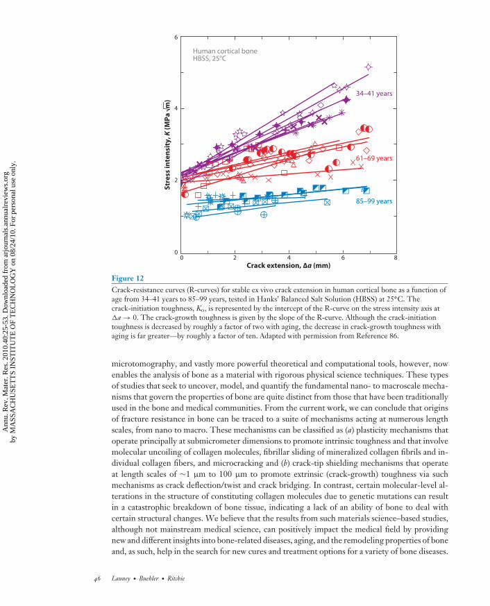
Despite the development of such fracture resistance in human bone, the risk of bone fractureincreases markedly with aging. As noted above, this increase in risk has been traditionally relatedto a loss in bone mass (osteoporosis), but we now realize that there is an additional degradation inthe quality of bone with age. Fracture toughness measurements on 34–99-year-old human corticalbone show some 40% reduction in the crack-initiation toughness and almost complete eliminationof the crack-growth toughness with increasing age (Figure 12) (86). The reasons for this arecomplex and not totally clear (79, 86). With aging, at the nanoscale there are distinct changes inthe collagen environment specifically with regard to an increased degree of cross-linking: At thesubmicrometer scale, the nature and properties of individual collagen fibrils deteriorate, and atthe scale of 1 μm to 100 μm, the microstructure at the bone level changes due to an increaseddensity of osteons, the latter having perhaps the largest effect on the macroscale fracture toughnessproperties (79). With progressive aging, human bone is remodeled at the interior of the cortex(Haversian remodeling), which then stimulates further remodeling as the growing cement linessever the tiny canals that connect interstitial bone cells, leading to cell death (16). As a result, thedensity of osteons increases with age (79). Because the cement lines provide the prime sites formicrocrack formation, the increased osteon density gives rise to (a) a higher microcrack density,which can be associated with a diminished crack-initiation toughness, and more importantly to(b) smaller uncracked-ligament bridges spanning the crack, which in turn significantly degrade thecrack-growth toughness. Such age-induced degradation in the potency of crack bridging in bonehas been directly measured and is a major reason for the severe reduction in fracture resistance ofbone with aging (31, 79).
44 Launey · Buehler · Ritchie
Ann
u. R
ev. M
ater
. Res
. 201
0.40
:25-
53. D
ownl
oade
d fr
om a
rjou
rnal
s.an
nual
revi
ews.
org
by M
ASS
AC
HU
SET
TS
INST
ITU
TE
OF
TE
CH
NO
LO
GY
on
08/2
4/10
. For
per
sona
l use
onl
y.
MR40CH02-Ritchie ARI 3 June 2010 23:9
No
rma
liz
ed
str
en
gth
Cross-link-deficient fibril
Highly cross-linked fibril
Experimental(oim tendon)
Reference
Mutation
Stress+
–
1.2
1.0
0.8
0.6
0.4
0.2
0.0
8
7
6
5
4
3
2
1
00.0 0.2 0.4 0.6 0.8
Str
ess
(G
Pa
)
Engineering strain
a
b
c
Disease states
Reference
Mutated
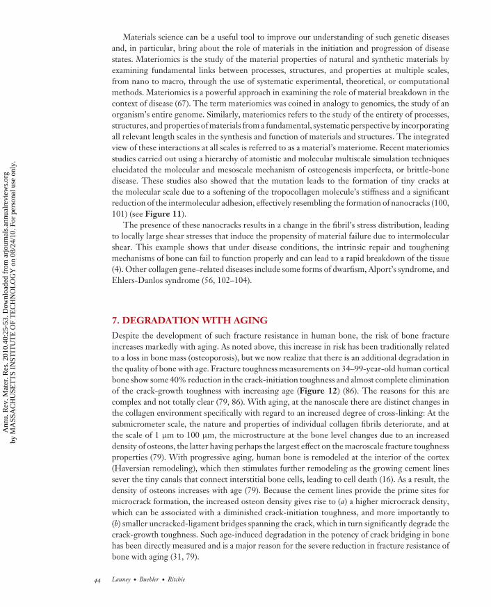
Figure 11Effects of osteogenesis imperfecta mutations on mechanical properties of collagenous tissues, based oncomputational multiscale (100, 101) and experimental (99) results. Panel a shows the effect of the mutationson the strength properties of collagen fibrils and tendon. Panel b shows two stress-strain curves representingthe reference case without mutations and the mutated sample. A severe change in the stress-strain responsecan be observed. Panel c schematically highlights the effect of the mutations on the internal stressdistribution, where the formation of nanocracks leads to large shear stresses inside the fibril.
8. CLOSING REMARKS
Because bone is such a complex biological material, we still possess only a limited quantitative un-derstanding of how it deforms and fractures or of the salient plasticity and toughening mechanismsactive at the various structural length scales and timescales. The advent of multiscale observations,high-resolution structural imaging using transmission electron microscopy and computed X-ray
www.annualreviews.org • On the Mechanistic Origins of Toughness in Bone 45
Ann
u. R
ev. M
ater
. Res
. 201
0.40
:25-
53. D
ownl
oade
d fr
om a
rjou
rnal
s.an
nual
revi
ews.
org
by M
ASS
AC
HU
SET
TS
INST
ITU
TE
OF
TE
CH
NO
LO
GY
on
08/2
4/10
. For
per
sona
l use
onl
y.
MR40CH02-Ritchie ARI 3 June 2010 23:9
Crack extension, Δa (mm)
Str
ess
in
ten
sity
, K (
MP
a m
)
Human cortical boneHBSS, 25°C
0
2
4
6
0 2 4 6 8
34–41 years
61–69 years
85–99 years
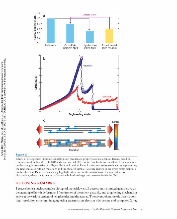
Figure 12Crack-resistance curves (R-curves) for stable ex vivo crack extension in human cortical bone as a function ofage from 34–41 years to 85–99 years, tested in Hanks’ Balanced Salt Solution (HBSS) at 25◦C. Thecrack-initiation toughness, Ko, is represented by the intercept of the R-curve on the stress intensity axis at�a → 0. The crack-growth toughness is given by the slope of the R-curve. Although the crack-initiationtoughness is decreased by roughly a factor of two with aging, the decrease in crack-growth toughness withaging is far greater—by roughly a factor of ten. Adapted with permission from Reference 86.
microtomography, and vastly more powerful theoretical and computational tools, however, nowenables the analysis of bone as a material with rigorous physical science techniques. These typesof studies that seek to uncover, model, and quantify the fundamental nano- to macroscale mecha-nisms that govern the properties of bone are quite distinct from those that have been traditionallyused in the bone and medical communities. From the current work, we can conclude that originsof fracture resistance in bone can be traced to a suite of mechanisms acting at numerous lengthscales, from nano to macro. These mechanisms can be classified as (a) plasticity mechanisms thatoperate principally at submicrometer dimensions to promote intrinsic toughness and that involvemolecular uncoiling of collagen molecules, fibrillar sliding of mineralized collagen fibrils and in-dividual collagen fibers, and microcracking and (b) crack-tip shielding mechanisms that operateat length scales of ∼1 μm to 100 μm to promote extrinsic (crack-growth) toughness via suchmechanisms as crack deflection/twist and crack bridging. In contrast, certain molecular-level al-terations in the structure of constituting collagen molecules due to genetic mutations can resultin a catastrophic breakdown of bone tissue, indicating a lack of an ability of bone to deal withcertain structural changes. We believe that the results from such materials science–based studies,although not mainstream medical science, can positively impact the medical field by providingnew and different insights into bone-related diseases, aging, and the remodeling properties of boneand, as such, help in the search for new cures and treatment options for a variety of bone diseases.
46 Launey · Buehler · Ritchie
Ann
u. R
ev. M
ater
. Res
. 201
0.40
:25-
53. D
ownl
oade
d fr
om a
rjou
rnal
s.an
nual
revi
ews.
org
by M
ASS
AC
HU
SET
TS
INST
ITU
TE
OF
TE
CH
NO
LO
GY
on
08/2
4/10
. For
per
sona
l use
onl
y.
MR40CH02-Ritchie ARI 3 June 2010 23:9
DISCLOSURE STATEMENT
The authors are not aware of any affiliations, memberships, funding, or financial holdings thatmight be perceived as affecting the objectivity of this review.
ACKNOWLEDGMENTS
This work was supported by the Laboratory Directed Research and Development Program ofLawrence Berkeley National Laboratory (LBNL) and by the Office of Science, Office of BasicEnergy Sciences, Division of Materials Sciences and Engineering of the U.S. Department ofEnergy under contract number DE-AC02-05CH11231. The use of the X-ray synchrotron mi-crotomography beam line (8.3.2) at the Advanced Light Source at LBNL, supported by the Officeof Science of the U.S. Department of Energy, is also acknowledged. M.J.B. acknowledges sup-port from the Army Research Office (contract number W911NF-06-1-0291) and support froma National Science Foundation CAREER award (contract number 0642545). The authors wouldlike to thank many individuals who have been engaged in various parts of this work, including JoelAger, Sabine Bechtle, Tony Keaveny, John Kinney, Kurt Koester, Jay Kruzic, Joanna McKittrick,Ravi Nalla, Eduardo Saiz, and Tony Tomsia.
APPENDIX: QUANTITATIVE ASSESSMENT OF TOUGHNESS IN BONE
As described above, significant efforts have been made over the past ten years or so to elucidatehow bone is toughened. One important aspect of such efforts is how to quantitatively measurethe macroscopic toughness of bone. Traditionally, this has been achieved by measurements ofthe work of fracture, Wf , which is obtained by dividing the area under the load-displacementcurve measured during the toughness test by twice the nominal crack-surface area. This approachhas been widely used in the past to quantify the toughness of cortical bone in unnotched (nominallyflaw-free) specimens (16, 17, 105–110) but suffers from the fact that the results can be dependenton both specimen size and geometry. Consequently, work-of-fracture measurements are generallynot too useful for comparing toughness values determined in different studies that utilized differentsample geometries, but they may be used successfully to assess trends when the nominal samplesize and geometry are held constant.
The fracture of bone, akin to that of other structural materials, is best characterized usingfracture mechanics methods. In its simplest form, this involves linear-elastic fracture mechanics(LEFM) assessments of toughness, which have been widely used for bone. Here we must makean assumption that bone is a linear-elastic material, specifically that any inelastic (e.g., yielding)behavior is limited to a small near-tip region such that the stress and displacement fields local to thetip of a preexisting crack can be described by the stress-intensity factor, K, where K can be definedfor mode I (tensile-opening loading), for mode II (shear loading), or for mode III (tearing orantishear loading) (97, 111). There is a large body of results in the literature involving assessmentsof the fracture toughness of cortical bone using LEFM. Such works have involved single-parametercharacterization of the toughness using either the critical value of the mode I linear-elastic stressintensity, KIc (110, 112–115), or the related strain-energy release rate, Gc (116, 117).4
4The fracture toughness, Kic (where i = I, II, or III), is the critical value of the stress intensity K for unstable fracture in thepresence of a preexisting crack, e.g., in mode I when KI = Yσ app(πa)1/2 = KIc , where σ app is the applied stress, a is the cracklength, and Y is a function (of order unity) of crack size and geometry. The alternative LEFM approach is to express thetoughness as a critical value of the strain-energy release rate, Gc , defined as the change in potential energy per unit increase in
www.annualreviews.org • On the Mechanistic Origins of Toughness in Bone 47
Ann
u. R
ev. M
ater
. Res
. 201
0.40
:25-
53. D
ownl
oade
d fr
om a
rjou
rnal
s.an
nual
revi
ews.
org
by M
ASS
AC
HU
SET
TS
INST
ITU
TE
OF
TE
CH
NO
LO
GY
on
08/2
4/10
. For
per
sona
l use
onl
y.
MR40CH02-Ritchie ARI 3 June 2010 23:9
Whereas such a fracture mechanics approach represents a significant improvement over mea-surements of toughness involving parameters such as the work of fracture, single-value linear-elastic fracture parameters based on crack initiation, such as KIc, cannot capture, or even repre-sent, the multiple length-scale toughening acting in cortical bone. As described in this article,although intrinsic (deformation) mechanisms govern primarily the crack-initiation toughness, thepredominant toughening mechanisms in bone are extrinsic and hence operate largely in the wakeof the crack to govern the crack-growth toughness. This results in some degree of stable crackingbefore unstable fracture, leading to characteristic resistance-curve (R-curve) behavior (76, 77, 86,94, 118, 119), where the fracture resistance actually increases with crack extension.5
Although such linear-elastic stress-intensity-based R-curves do provide a means to characterizecrack propagation, the underlying assumptions for such KR calculations do not account for theenergy associated with plastic deformation during bone fracture, which is associated with intrinsictoughening in bone. The LEFM approach is valid only where small-scale yielding conditionsapply (111), i.e., where the extent of local (crack-tip) inelasticity is small compared with the size ofthe bone or test sample. This places restrictions on how large a test specimen has to be for validtoughness measurements; namely, the in-plane specimen dimensions of crack size and the width ofthe remaining uncracked ligament must be at least an order of magnitude larger than the plastic-zone size (small-scale yielding). Additionally, for geometry- and thickness-independent toughnessvalues, the out-of-plane thickness dimension must be equally larger than the plastic zone (planestrain conditions). For example, in antler bone, a LEFM KIc value of ∼10 MPa
√m (120) would
require test specimen dimensions (in terms of crack size, ligament depth, and thickness) in excessof 50 mm for a valid linear-elastic KIc based on current ASTM validity criteria (121). Because thethickness of the cortical shell in antler bone is typically only ∼5 mm, LEFM KIc measurementsare not an appropriate means to measure its toughness; the distribution in local stresses anddisplacements near a crack tip (i.e., near the fracture origin) would not be represented by theK-field (122) such that the resulting K-based toughness values would be highly questionable. Thismay not be the situation for all bones, but in the majority of cases, the bone size in comparison tothe extent of local plasticity will be insufficient for LEFM toughness measurements to be reliable(or independent of geometry and size).
Accordingly, to assess the toughness of bone material, with its large postyield deformation andsubcritical cracking behavior, an R-curve approach based on a nonlinear-elastic fracture mechanicsapproach is essential to provide a more realistic description of the crack-tip stress and displacementfields and furthermore is able to capture the contribution to the toughness from the energyconsumed in plastic deformation prior to and during fracture (80, 123). The best approach hereappears to be the use of the J-integral as the crack-driving force, where J is the nonlinear strain-energy release rate, i.e., the rate of change in potential energy for a unit increase in crack areain a nonlinear-elastic solid (the nonlinear-elastic equivalent of G). In analogous fashion to Kin linear-elastic materials, J characterizes the stress and displacement fields at a crack tip in anonlinear-elastic solid and as such can be used to define the onset of fracture in such a material.Descriptions of the use of J-integral measurements for bone can be found in References 80, 81,91, and 123. Indeed, J-integral measurements have now been used to quantify the toughness of
crack area. The relationship between these two parameters is given by G = K 2I
E + K 2II
E + K 2III
2μ, where E and μ are the Young’s
modulus and shear modulus, respectively.5The R-curve provides an assessment of the fracture toughness in the presence of subcritical crack growth. It involvesmeasurements of the crack-driving force, e.g., K or J, as a function of crack extension (�a). The value of the driving force at�a → 0 provides a measure of the crack-initiation toughness, whereas the slope (or maximum value) of the R-curve can beused to characterize the crack-growth toughness.
48 Launey · Buehler · Ritchie
Ann
u. R
ev. M
ater
. Res
. 201
0.40
:25-
53. D
ownl
oade
d fr
om a
rjou
rnal
s.an
nual
revi
ews.
org
by M
ASS
AC
HU
SET
TS
INST
ITU
TE
OF
TE
CH
NO
LO
GY
on
08/2
4/10
. For
per
sona
l use
onl
y.
MR40CH02-Ritchie ARI 3 June 2010 23:9
several biological materials, including bone (80, 81, 91, 123), dentin (124), and nacre (125). In thiswork, the majority of fracture toughness and R-curve measurements shown were performed usingnonlinear-elastic fracture mechanics, although for clarity, back-calculated K values are presented.
LITERATURE CITED
1. Aizenberg J, Weaver JC, Thanawala MS, Sundar VC, Morse DE, Fratzl P. 2005. Skeleton of Euplectellasp.: structural hierarchy from the nanoscale to the macroscale. Science 309:275–78
2. Fratzl P, Weinkamer R. 2007. Nature’s hierarchical materials. Prog. Mater. Sci. 52:1263–3343. Espinosa HD, Rim JE, Barthelat F, Buehler MJ. 2009. Merger of structure and material in nacre and
bone: perspectives on de novo biomimetic materials. Prog. Mater. Sci. 54:1059–1004. Buehler MJ, Yung YC. 2009. Deformation and failure of protein materials in physiologically extreme
conditions and disease. Nat. Mater. 8:175–885. Aizenberg J, Fratzl P. 2009. Biological and biomimetic materials. Adv. Mater. 21:387–886. Ortiz C, Boyce MC. 2008. Materials science: bioinspired structural materials. Science 319:1053–547. Mayer G. 2005. Rigid biological systems as models for synthetic composites. Science 310:1144–478. Currey JD. 2005. Materials science: hierarchies in biomineral structures. Science 309:253–549. Lakes R. 1993. Materials with structural hierarchy. Nature 361:511–15
10. Jeronimidis G, Atkins AG. 1995. Mechanics of biological materials and structures: nature’s lessons forthe engineer. Proc. Inst. Mech. Eng. C 209:221–35
11. Ackbarow T, Sen D, Thaulow C, Buehler MJ. 2009. Alpha-helical protein networks are self-protectiveand flaw-tolerant. PLoS ONE 4:e6015
12. Qin Z, Kreplak L, Buehler MJ. 2009. Hierarchical structure controls nanomechanical properties ofvimentin intermediate filaments. PLoS ONE 4:e7294
13. Jeronimidis G. 2000. Structure-property relationships in biological materials. In Structural BiologicalMaterials, Design and Structure-Property Relationships, ed. M Elices, pp. 3–29. Amsterdam: Pergamon
14. Fratzl P. 2007. Biomimetic materials research: What can we really learn from nature’s structural mate-rials? J. R. Soc. Interface 4:637–42
15. Meyers MA, Chen PY, Lin AYM, Seki Y. 2008. Biological materials: structure and mechanical properties.Prog. Mater. Sci. 53:1–206
16. Currey JD. 2002. Bones. Princeton: Princeton Univ. Press17. Currey JD. 1979. Mechanical properties of bone tissues with greatly different functions. J. Biomech.
12:313–1918. Currey JD. 1999. The design of mineralised hard tissues for their mechanical functions. J. Exp. Biol.
202:3285–9419. Martin RB, Burr DB. 1989. Structure, Function, and Adaptation of Compact Bone. New York: Raven20. Taylor D. 2003. Failure processes in hard and soft tissues. In Comprehensive Structural Integrity: Fracture
of Materials from Nano to Macro, ed. I Milne, RO Ritchie, BL Karihaloo, pp. 35–95. Oxford, UK: Elsevier21. Taylor D, Hazenberg JG, Lee TC. 2007. Living with cracks: damage and repair in human bone. Nat.
Mater. 6:263–6822. Hui SL, Slemenda CW, Johnston CC. 1988. Age and bone mass as predictors of fracture in a prospective
study. J. Clin. Investig. 81:1804–923. Kiebzak GM. 1991. Age-related bone changes. Exp. Gerontol. 26:171–8724. Heaney RP. 2003. Is the paradigm shifting? Bone 33:457–6525. Rho JY, Kuhn-Spearing L, Zioupos P. 1998. Mechanical properties and the hierarchical structure of
bone. Med. Eng. Phys. 20:92–10226. Weiner S, Wagner HD. 1998. The material bone: structure mechanical function relations. Annu. Rev.
Mater. Sci. 28:271–9827. Ritchie RO. 1988. Mechanisms of fatigue crack-propagation in metals, ceramics and composites: role of
crack tip shielding. Mater. Sci. Eng. A 103:15–2828. Launey ME, Ritchie RO. 2009. On the fracture toughness of advanced materials. Adv. Mater. 21:2103–10
www.annualreviews.org • On the Mechanistic Origins of Toughness in Bone 49
Ann
u. R
ev. M
ater
. Res
. 201
0.40
:25-
53. D
ownl
oade
d fr
om a
rjou
rnal
s.an
nual
revi
ews.
org
by M
ASS
AC
HU
SET
TS
INST
ITU
TE
OF
TE
CH
NO
LO
GY
on
08/2
4/10
. For
per
sona
l use
onl
y.
MR40CH02-Ritchie ARI 3 June 2010 23:9
29. Ritchie RO. 1999. Mechanisms of fatigue-crack propagation in ductile and brittle solids. Int. J. Fract.100:55–83
30. Evans AG. 1990. Perspective on the development of high-toughness ceramics. J. Am. Ceram. Soc. 73:187–206
31. Nalla RK, Kinney JH, Ritchie RO. 2003. Mechanistic fracture criteria for the failure of human corticalbone. Nat. Mater. 2:164–68
32. Ritchie RO, Buehler MJ, Hansma PK. 2009. Plasticity and toughness in bone. Phys. Today 62:41–4733. Fratzl P, Gupta HS, Paschalis EP, Roschger P. 2004. Structure and mechanical quality of the collagen-
mineral nano-composite in bone. J. Mater. Chem. 14:2115–2334. Skedros JG, Durand P, Bloebaum RD. 1995. Hypermineralized peripheral lamellae in primary osteons
of deer antler: potential functional analogs of cement lines in mammalian secondary bone. J. Bone Miner.Res. 10(Suppl. 1):S441
35. Skedros JG, Holmes JL, Vajda EG, Bloebaum RD. 2005. Cement lines of secondary osteons in humanbone are not mineral-deficient: new data in a historical perspective. Anat. Rec. A 286:781–803
36. Burr DB, Schaffler MB, Frederickson RG. 1988. Composition of the cement line and its possible me-chanical role as a local interface inhuman compact-bone. J. Biomech. 21:939–45
37. Yeni YN, Norman TL. 2000. Calculation of porosity and osteonal cement line effects on the effectivefracture toughness of cortical bone in longitudinal crack growth. J. Biomed. Mater. Res. 51:504–9
38. Weiner S, Traub W, Wagner HD. 1999. Lamellar bone: structure-function relations. J. Struct. Biol.126:241–55
39. Giraud-Guille MM. 1988. Twisted plywood architecture of collagen fibrils in human compact-boneosteons. Calcif. Tissue Int. 42:167–80
40. Ascenzi A, Bonucci E, Generali P, Ripamonti A, Roveri N. 1979. Orientation of apatite in single osteonsamples as studied by pole figures. Calcif. Tissue Int. 29:101–5
41. Rho JY, Zioupos P, Currey JD, Pharr GM. 1999. Variations in the individual thick lamellar propertieswithin osteons by nanoindentation. Bone 25:295–300
42. Wagermaier W, Gupta HS, Gourrier A, Burghammer M, Roschger P, Fratzl P. 2006. Spiral twisting offiber orientation inside bone lamellae. Biointerphases 1:1–5
43. Wagermaier W, Gupta HS, Gourrier A, Paris O, Roschger P, et al. 2007. Scanning texture analysis oflamellar bone using microbeam synchrotron X-ray radiation. J. Appl. Crystallogr. 40:115–20
44. Landis WJ, Hodgens KJ, Arena J, Song MJ, McEwen BF. 1996. Structural relations between collagenand mineral in bone as determined by high voltage electron microscopic tomography. Microsc. Res. Tech.33:192–202
45. Landis WJ, Hodgens KJ, Song MJ, Arena J, Kiyonaga S, et al. 1996. Mineralization of collagen mayoccur on fibril surfaces: evidence from conventional and high-voltage electron microscopy and three-dimensional imaging. J. Struct. Biol. 117:24–35
46. Fratzl P, Fratzlzelman N, Klaushofer K, Vogl G, Koller K. 1991. Nucleation and growth of mineralcrystals in bone studied by small angle X-ray scattering. Calcif. Tissue Int. 48:407–13
47. Fratzl P, Groschner M, Vogl G, Plenk H, Eschberger J, et al. 1992. Mineral crystals in calcified tissues:a comparative study by SAXS. J. Bone Miner. Res. 7:329–34
48. Glimcher MJ. 1984. Recent studies of the mineral phase in bone and its possible linkage to the organicmatrix by protein bound phosphate bonds. Philos. Trans. R. Soc. Lond. Ser. B 304:479–508
49. Grynpas MD, Bonar LC, Glimcher MJ. 1984. X-ray diffraction radial distribution function studies onbone mineral and synthetic calcium phosphates. J. Mater. Sci. 19:723–36
50. Posner AS. 1985. The mineral of bone. Clin. Orthop. Relat. Res. 200:87–9951. Rubin MA, Rubin J, Jasiuk W. 2004. SEM and TEM study of the hierarchical structure of C57BL/6J
and C3H/HeJ mice trabecular bone. Bone 35:11–2052. Gao HJ, Ji BH, Jager IL, Arzt E, Fratzl P. 2003. Materials become insensitive to flaws at nanoscale:
lessons from nature. Proc. Natl. Acad. Sci. USA 100:5597–60053. Ramachandran GN, Kartha G. 1955. Structure of collagen. Nature 176:593–9554. Canty EG, Kadler KE. 2002. Collagen fibril biosynthesis in tendon: a review and recent insights. Comp.
Biochem. Physiol. A 133:979–85
50 Launey · Buehler · Ritchie
Ann
u. R
ev. M
ater
. Res
. 201
0.40
:25-
53. D
ownl
oade
d fr
om a
rjou
rnal
s.an
nual
revi
ews.
org
by M
ASS
AC
HU
SET
TS
INST
ITU
TE
OF
TE
CH
NO
LO
GY
on
08/2
4/10
. For
per
sona
l use
onl
y.
MR40CH02-Ritchie ARI 3 June 2010 23:9
55. Kadler KE, Holmes DF, Trotter JA, Chapman JA. 1996. Collagen fibril formation. Biochem. J. 316:1–1156. Prockop DJ, Kivirikko KI. 1995. Collagens: molecular biology, diseases, and potentials for therapy.
Annu. Rev. Biochem. 64:403–3457. Prockop DJ, Kivirikko KI. 1984. Heritable diseases of collagen. New Engl. J. Med. 311:376–8658. Ackbarow T, Chen X, Keten S, Buehler MJ. 2007. Hierarchies, multiple energy barriers, and robustness
govern the fracture mechanics of alpha-helical and beta-sheet protein domains. Proc. Natl. Acad. Sci. USA104:16410–15
59. Keten S, Buehler MJ. 2008. Asymptotic strength limit of hydrogen-bond assemblies in proteins atvanishing pulling rates. Phys. Rev. Lett. 100:198301
60. Keten S, Buehler MJ. 2008. Strength limit of entropic elasticity in beta-sheet protein domains. Phys. Rev.E 78:061913
61. Sun YL, Luo ZP, Fertala A, An KN. 2004. Stretching type II collagen with optical tweezers. J. Biomech.37:1665–69
62. Buehler MJ. 2008. Nanomechanics of collagen fibrils under varying cross-link densities: atomistic andcontinuum studies. J. Mech. Behav. Biomed. Mater. 1:59–67
63. Buehler MJ. 2006. Atomistic and continuum modeling of mechanical properties of collagen: elasticity,fracture, and self-assembly. J. Mater. Res. 21:1947–61
64. Buehler MJ, Wong SY. 2007. Entropic elasticity controls nanomechanics of single tropocollagenmolecules. Biophys. J. 93:37–43
65. Gautieri A, Buehler MJ, Redaelli A. 2009. Deformation rate controls elasticity and unfolding pathwayof single tropocollagen molecules. J. Mech. Behav. Biomed. Mater. 2:130–37
66. Buehler MJ. 2007. Molecular nanomechanics of nascent bone: fibrillar toughening by mineralization.Nanotechnology 18:295102
67. Buehler MJ, Keten S, Ackbarow T. 2008. Theoretical and computational hierarchical nanomechanics ofprotein materials: deformation and fracture. Prog. Mater. Sci. 53:1101–241
68. Fantner GE, Hassenkam T, Kindt JH, Weaver JC, Birkedal H, et al. 2005. Sacrificial bonds and hiddenlength dissipate energy as mineralized fibrils separate during bone fracture. Nat. Mater. 4:612–16
69. Craig AS, Birtles MJ, Conway JF, Parry DAD. 1989. An estimate of the mean length of collagen fibrilsin rat tail-tendon as a function of age. Connect. Tissue Res. 19:51–62
70. Gupta HS, Wagermaier W, Zickler GA, Aroush DRB, Funari SS, et al. 2005. Nanoscale deformationmechanisms in bone. Nano Lett. 5:2108–11
71. Smith BL, Schaffer TE, Viani M, Thompson JB, Frederick NA, et al. 1999. Molecular mechanistic originof the toughness of natural adhesives, fibres and composites. Nature 399:761–63
72. Fantner GE, Oroudjev E, Schitter G, Golde LS, Thurner P, et al. 2006. Sacrificial bonds and hiddenlength: unraveling molecular mesostructures in tough materials. Biophys. J. 90:1411–18
73. Bonar LC, Lees S, Mook HA. 1985. Neutron-diffraction studies of collagen in fully mineralized bone.J. Mol. Biol. 181:265–70
74. Tai K, Ulm FJ, Ortiz C. 2006. Nanogranular origins of the strength of bone. Nano Lett. 6:2520–2575. Zioupos P, Currey JD. 1994. The extent of microcracking and the morphology of microcracks in damaged
bone. J. Mater. Sci. 29:978–8676. Vashishth D, Behiri JC, Bonfield W. 1997. Crack growth resistance in cortical bone: concept of micro-
crack toughening. J. Biomech. 30:763–6977. Vashishth D, Tanner KE, Bonfield W. 2003. Experimental validation of a microcracking-based tough-
ening mechanism for cortical bone. J. Biomech. 36:121–2478. Vashishth D, Tanner KE, Bonfield W. 2000. Contribution, development and morphology of micro-
cracking in cortical bone during crack propagation. J. Biomech. 33:1169–7479. Nalla RK, Kruzic JJ, Kinney JH, Balooch M, Ager JW, Ritchie RO. 2006. Role of microstructure in the
aging-related deterioration of the toughness of human cortical bone. Mater. Sci. Eng. C 26:1251–6080. Koester KJ, Ager JW, Ritchie RO. 2008. The true toughness of human cortical bone measured with
realistically short cracks. Nat. Mater. 7:672–7781. Peterlik H, Roschger P, Klaushofer K, Fratzl P. 2006. From brittle to ductile fracture of bone. Nat.
Mater. 5:52–55
www.annualreviews.org • On the Mechanistic Origins of Toughness in Bone 51
Ann
u. R
ev. M
ater
. Res
. 201
0.40
:25-
53. D
ownl
oade
d fr
om a
rjou
rnal
s.an
nual
revi
ews.
org
by M
ASS
AC
HU
SET
TS
INST
ITU
TE
OF
TE
CH
NO
LO
GY
on
08/2
4/10
. For
per
sona
l use
onl
y.
MR40CH02-Ritchie ARI 3 June 2010 23:9
82. Yeni YN, Fyhrie DP. 2003. A rate-dependent microcrack-bridging model that can explain the strain ratedependency of cortical bone apparent yield strength. J. Biomech. 36:1343–53
83. Nalla RK, Stolken JS, Kinney JH, Ritchie RO. 2005. Fracture in human cortical bone: local fracturecriteria and toughening mechanisms. J. Biomech. 38:1517–25
84. Zimmermann EA, Launey ME, Barth HB, Ritchie RO. 2009. Mixed-mode fracture of human corticalbone. Biomaterials 30:5877–84
85. Parsamian GP, Norman TL. 2001. Diffuse damage accumulation in the fracture process zone of humancortical bone specimens and its influence on fracture toughness. J. Mater. Sci. Mater. Med. 12:779–83
86. Nalla RK, Kruzic JJ, Kinney JH, Ritchie RO. 2004. Effect of aging on the toughness of human corticalbone: evaluation by R-curves. Bone 35:1240–46
87. Nalla RK, Kruzic JJ, Ritchie RO. 2004. On the origin of the toughness of mineralized tissue: micro-cracking or crack bridging? Bone 34:790–98
88. Ritchie RO, Cannon RM, Dalgleish BJ, Dauskardt RH, McNaney JM. 1993. Mechanics and mechanismsof crack-growth at or near ceramic-metal interfaces: interface engineering strategies for promotingtoughness. Mater. Sci. Eng. A 166:221–35
89. Cotterell B, Rice JR. 1980. Slightly curved or kinked cracks. Int. J. Fract. 16:155–6990. Faber KT, Evans AG. 1983. Crack deflection processes. I. Theory. Acta Metall. 31:565–7691. Launey ME, Chen P-Y, McKittrick J, Ritchie RO. 2010. Mechanistic aspects of the fracture toughness
of elk antler bone. Acta Biomater. 6:1505–1492. Wegst UGK, Ashby MF. 2004. The mechanical efficiency of natural materials. Philos. Mag. 84:2167–8193. Zioupos P, Currey JD, Sedman AJ. 1994. An examination of the micromechanics of failure of bone and
antler by acoustic emission tests and laser scanning confocal microscopy. Med. Eng. Phys. 16:203–1294. Vashishth D. 2004. Rising crack-growth-resistance behavior in cortical bone: implications for toughness
measurements. J. Biomech. 37:943–4695. Krauss S, Fratzl P, Seto J, Currey JD, Estevez JA, et al. 2009. Inhomogeneous fibril stretching in antler
starts after macroscopic yielding: indication for a nanoscale toughening mechanism. Bone 44:1105–1096. Gupta HS, Seto J, Wagermaier W, Zaslansky P, Boesecke P, Fratzl P. 2006. Cooperative deformation
of mineral and collagen in bone at the nanoscale. Proc. Natl. Acad. Sci. USA 103:17741–4697. Ritchie RO, Koester KJ, Ionova S, Yao W, Lane NE, Ager JW. 2008. Measurement of the toughness of
bone: a tutorial with special reference to small animal studies. Bone 43:798–81298. Rauch F, Glorieux FH. 2004. Osteogenesis imperfecta. Lancet 363:1377–8599. Misof K, Landis WJ, Klaushofer K, Fratzl P. 1997. Collagen from the osteogenesis imperfecta mouse
model (oim) shows reduced resistance against tensile stress. J. Clin. Investig. 100:40–45100. Gautieri A, Uzel S, Vesentini S, Redaelli A, Buehler MJ. 2009. Molecular and mesoscale mechanisms of
osteogenesis imperfecta disease in collagen fibrils. Biophys. J. 97:857–65101. Gautieri A, Vesentini S, Redaelli A, Buehler MJ. 2009. Single molecule effects of osteogenesis imperfecta
mutations in tropocollagen protein domains. Protein Sci. 18:161–68102. Turner AN, Rees AJ. 1996. Goodpasture’s disease and Alport’s syndromes. Annu. Rev. Med. 47:377–86103. Tryggvason K, Jing Z, Hostikka SL, Shows TB. 1993. Molecular-genetics of Alport syndrome. Kidney
Int. 43:38–44104. Srinivasan M, Uzel SGM, Gautieri A, Keten S, Buehler MJ. 2009. Alport syndrome mutations in type
IV tropocollagen alter molecular structure and nanomechanical properties. J. Struct. Biol. 168:503–10105. Currey JD. 1979. Changes in the impact energy-absorption of bone with age. J. Biomech. 12:459–69106. Currey JD, Brear K, Zioupos P. 1996. The effects of ageing and changes in mineral content in degrading
the toughness of human femora. J. Biomech. 29:257–60107. Zioupos P, Currey JD. 1998. Changes in the stiffness, strength, and toughness of human cortical bone
with age. Bone 22:57–66108. Wang X, Shen X, Li X, Agrawal CM. 2002. Age-related changes in the collagen network and toughness
of bone. Bone 31:1–7109. Wang XD, Bank RA, TeKoppele JM, Agrawal CM. 2001. The role of collagen in determining bone
mechanical properties. J. Orthop. Res. 19:1021–26110. Lucksanasombool P, Higgs WAJ, Higgs R, Swain MV. 2001. Fracture toughness of bovine bone: influ-
ence of orientation and storage media. Biomaterials 22:3127–32
52 Launey · Buehler · Ritchie
Ann
u. R
ev. M
ater
. Res
. 201
0.40
:25-
53. D
ownl
oade
d fr
om a
rjou
rnal
s.an
nual
revi
ews.
org
by M
ASS
AC
HU
SET
TS
INST
ITU
TE
OF
TE
CH
NO
LO
GY
on
08/2
4/10
. For
per
sona
l use
onl
y.
MR40CH02-Ritchie ARI 3 June 2010 23:9
111. Knott JF. 1973. Fundamentals of Fracture Mechanics. London: Butterworths112. Bonfield W. 1987. Advances in the fracture mechanics of cortical bone. J. Biomech. 20:1071–81113. Phelps JB, Hubbard GB, Wang X, Agrawal CM. 2000. Microstructural heterogeneity and the fracture
toughness of bone. J. Biomed. Mater. Res. 51:735–41114. Wang XD, Masilamani NS, Mabrey JD, Alder ME, Agrawal CM. 1998. Changes in the fracture toughness
of bone may not be reflected in its mineral density, porosity, and tensile properties. Bone 23:67–72115. Akkus O, Adar F, Schaffler MB. 2004. Age-related changes in physicochemical properties of mineral
crystals are related to impaired mechanical function of cortical bone. Bone 34:443–53116. Brown CU, Yeni YN, Norman TL. 2000. Fracture toughness is dependent on bone location: a study of
the femoral neck, femoral shaft, and the tibial shaft. J. Biomed. Mater. Res. 49:380–89117. Norman TL, Vashishth D, Burr DB. 1995. Fracture toughness of human bone under tension. J. Biomech.
28:309–20118. Nalla RK, Kruzic JJ, Kinney JH, Ritchie RO. 2005. Mechanistic aspects of fracture and R-curve behavior
in human cortical bone. Biomaterials 26:217–31119. Malik CL, Stover SM, Martin RB, Gibeling JC. 2003. Equine cortical bone exhibits rising R-curve
fracture mechanics. J. Biomech. 36:191–98120. Chen PY, Stokes AG, McKittrick J. 2009. Comparison of the structure and mechanical properties of
bovine femur bone and antler of the North American elk (Cervus elaphus canadensis). Acta Biomater.5:693–706
121. ASTM E1820-08. 2008. Annual Book of ASTM Standards, Vol. 03.0. Metals: Mechanical Testing; Elevatedand Low-Temperature Tests; Metallography. West Conshohocken, PA: ASTM Int.
122. Grellmann W. 2001. New developments in toughness evaluation of polymers and compounds by fracturemechanics. In Deformation and Fracture Behavior of Polymers, ed. W Grellmann, S Seidler, pp. 3–26.New York: Springer-Verlag
123. Yan JH, Mecholsky JJ, Clifton KB. 2007. How tough is bone? Application of elastic-plastic fracturemechanics to bone. Bone 40:479–84
124. Yan JH, Taskonak B, Platt JA, Mecholsky JJ. 2008. Evaluation of fracture toughness of human dentinusing elastic-plastic fracture mechanics. J. Biomech. 41:1253–59
125. Barthelat F, Espinosa HD. 2007. An experimental investigation of deformation and fracture of nacre-mother of pearl. Exp. Mech. 47:311–24
126. Yang QD, Cox BN, Nalla RK, Ritchie RO. 2006. Re-evaluating the toughness of human cortical bone.Bone 38:878–87
www.annualreviews.org • On the Mechanistic Origins of Toughness in Bone 53
Ann
u. R
ev. M
ater
. Res
. 201
0.40
:25-
53. D
ownl
oade
d fr
om a
rjou
rnal
s.an
nual
revi
ews.
org
by M
ASS
AC
HU
SET
TS
INST
ITU
TE
OF
TE
CH
NO
LO
GY
on
08/2
4/10
. For
per
sona
l use
onl
y.


![B156RW01 Functional Spec V1 1A-LED-01-DG-070909 V.1.pdf · Functional Block Diagram ... Screen Diagonal [mm] 394.87, 15.6” ... Product Specification B156RW01 V1 Document Version](https://img.pdfslide.net/doc/110x75/5b05a5f47f8b9ad5548bb5eb/b156rw01-functional-spec-v1-1a-led-01-dg-v1pdffunctional-block-diagram-screen.jpg)