Embed Size (px)
Citation preview
ISSN 1063�7761, Journal of Experimental and Theoretical Physics, 2011, Vol. 113, No. 1, pp. 27–45. © Pleiades Publishing, Inc., 2011.Original Russian Text © D.V. Karlovets, 2011, published in Zhurnal Eksperimental’noi i Teoreticheskoi Fiziki, 2011, Vol. 140, No. 1, pp. 36–55.
27
1. INTRODUCTION
The field of a charged particle moving uniformlyand rectilinearly in a medium may lead to dynamicpolarization of atomic shells and emission of radiationknown as polarization radiation in the microscopictheory [1]. In the macroscopic theory, the motion of aparticle through a medium (or near a medium) withsharp boundaries leads to various types of polarizationradiation: Cherenkov radiation (in the absence ofboundaries), transition radiation (the particle inter�sects the interface between two media), diffractionradiation (the particles moves near the interface), etc.The number of exact solutions to the problem ofpolarization radiation for media with sharp boundariesis small. The most important of the exactly solvableproblems are the problems of transition radiation in aplate with a finite permittivity [2], as well as diffractionradiation from a perfectly conducting half�plane [3, 4]and wedge [5, 6]. The solution of such problems inmore complex geometries is complicated by difficul�ties in the formulation of the boundary conditions. Itis well known, for example, that rigorous solution ofthe problem of radiation from a charge moving near aperfectly conducting grating (so�called Smith–Pur�cell radiation) is expressed by infinite series and leadsto a system of an infinitely large number of equations
[7, 8]. However, surfaces with intricate profiles aremost interesting for applications. For this reason, thedevelopment of approximate methods for solving theproblem of polarization radiation is topical.
In this paper, an approach is developed in whichpolarization radiation is represented as the field of thecurrent induced in a substance by the field of a pointcharge moving uniformly along a straight line. Theadvantage of this method lies in the possibility ofdetermining the characteristics of various types ofpolarization radiation (including the case when severaltypes of radiation are generated simultaneously) in awide range of surfaces taking into account actualdielectric properties of the substance and frequencydispersion. It will be shown that, in some special cases,the results obtained using the method developed hereare transformed into familiar expressions for Cheren�kov, transition, and diffraction radiation (as well asparametric X�ray radiation; see [9]).
The structure of the article is as follows. InSection 2, the method of induced currents is describedand the radiation field generated during the motion ofa charge along the axis of a cylindrical vacuum chan�nel in a screen with finite permittivity ε(ω) = ε' + iε'',thickness, and radius is described. The emergence ofradiation from the substance into a vacuum is consid�
On the Theory of Polarization Radiationin Media with Sharp Boundaries
D. V. KarlovetsNational Research Tomsk Polytechnic University, Tomsk, 634050 Russia
e�mail: [email protected] November 13, 2010
Abstract—Polarization radiation generated when a point charge moves uniformly along a straight line in vac�uum in the vicinity of media with a finite permittivity ε(ω) = ε' + iε'' and sharp boundaries is considered. Amethod is developed in which polarization radiation is represented as the field of the current induced in thesubstance by the field of the moving charge. The solution to the problem of radiation induced when a chargemoves along the axis of a cylindrical vacuum channel in a thin screen with a finite radius and a finite permit�tivity is obtained. Depending on the parameters of the problem, this solution describes various types of radi�ation (Cherenkov, transition, and diffraction radiation). In particular, when the channel radius tends to zeroand the outer radius of the screen tends to infinity, the expression derived for the emitted energy coincideswith the known solution for transition radiation in a plate. In another particular case of ideal conductivity(ε'' ∞), the relevant formula coincides with the known results for diffraction radiation from a circularaperture in an infinitely thin screen. The solution is obtained to the problem of radiation generated when thecharge flies near a thin rectangular screen with a finite permittivity. This solution describes the diffraction andCherenkov mechanisms of radiation and takes into account possible multiple re�reflections of radiation inthe screen. The solution to the problem of radiation generated when a particles flies near a thin grating con�sisting of a finite number of strips having a rectangular cross section and a finite permittivity and separated byvacuum gaps (Smith–Purcell radiation) is also obtained. In the special case of ideal conductivity, the expres�sion derived for the emitted energy coincides with the known result in the model of surface currents.
DOI: 10.1134/S1063776111050116
ATOMS, MOLECULES,OPTICS
28
JOURNAL OF EXPERIMENTAL AND THEORETICAL PHYSICS Vol. 113 No. 1 2011
KARLOVETS
ered, and the energy emitted into the vacuum in the“forward” and “backward” directions is determinedusing the well�known reciprocity theorem. InSection 3, the solution to the problem of radiationgenerated when a particle flies near a rectangularscreen of finite size and permittivity is obtained. Incontrast to the known solution, possible multiple re�reflections of the radiation field in the screen are takeninto account. In Section 4, the solution to the problemof radiation generated by a particle moving in thevicinity of a thin grating consisting of strips (plates) ofrectangular cross section and finite permittivity isobtained. The results, including the limit of applica�bility of the resultant solutions, are discussed in Sec�tion 5.
2. POLARIZATION RADIARION GENERATED IN A CYLINDRICAL CHANNEL IN A SCREEN
OF FINITE THICKNESS AND RADIUS
2.1. Radiation in a Screen with a Finite Permittivity
Let us consider a homogeneous isotropic nonmag�netic medium with a complex conductivity and withfrequency dispersion:
(1)
A charged particle possessing an energy
and moving at a constant velocity v = βc in the sub�stance induces in it a polarization currents of density
(2)
where E0 ≡ E0(r, ω), Epol ≡ Epol(r, ω) are the Fouriertransforms of the field of the particle in the vacuumand of the field of currents induced in the substance.
To determine the field of polarization radiationpropagating in the substance in the form of transversewaves, we must solve the “vacuum” Maxwell equa�tions with current density jpol on the right�hand side.However, Eq. (2) for the current density is an integralequation. The integral term can be disregarded if theconductivity of the medium is low ( � 1), whichmakes it possible to obtain the required solutions forthe X�ray part of the spectrum [9, 10]. In the generalcase, when parameter is not small, the field act�ing on each atom and molecule does not coincide withvacuum field E0 any longer. However, in this case alsowe can proceed in the same way as in deriving the mac�roscopic Maxwell equations. Transferring the integralterm with σEpol to the left�hand side of these equa�tions, we obtain the following equation for the mag�netic field:
σ ω( ) iω4π����� 1 ε ω( )–( ).=
γ E
mc2������� 1
1 β2–���������������= =
jpol σ E0 Epol jpol( )+( ),=
ε 1–
ε 1–
(3)
The solution to this equation in the wave zone gives thefield of polarization radiation emitted by atoms andmolecules of the substance as a result of so�called dis�tant collisions, in which the energy lost by a particle isnegligibly low as compared to its total energy. It will beshown below that this solution coincides with the fieldof Cherenkov radiation in an unbounded medium.
If the polarization currents are induced in a limitedvolume of the substance (i.e., the medium has bound�aries), the integration in the solution of Eq. (3) is per�formed only over the domain VT occupied by the cur�rents:
(4)
In a bounded volume of the substance, the wavesreflected from the boundaries, which cannot bedescribed by expression (4), also exist apart frompolarization radiation waves. However, such waves canbe taken into account at a later stage when the emer�gence of radiation from the medium into the vacuumwill be considered. Evaluating the curl in Eq. (4), weobtain
(5)
(the dependence of permittivity on frequency isimplied). It can be seen from this expression that thewave zone boundaries are defined by the following ine�qualities:
(6)
where determines the effective region in the sub�stance, occupied by currents and making the maincontribution to integral (5). It should be noted that thefirst of the conditions of the wave zone cannot be sat�isfied near permittivity zeros (for ε(ω) 0). Thiscorresponds to the well�known fact that there are notransverse waves propagating in the substance to infin�
Δ ε ω( )ω2
c2�����+⎝ ⎠
⎛ ⎞ Hpol r ω,( )
= 4πc
�����σ ω( )curlE0 r ω,( ).–
Hpol r ω,( ) curl1c�� σ ω( )E0 r ' ω,( )
VT
∫=
× i ε ω( )ω r r'– /c( )expr r '–
�����������������������������������������������d3r '.
Hpol r ω,( ) 1c�� r r '–
r r '–������������ σ ω( )E0 r ' ω,( )×
VT
∫=
× i εωc��� 1
r r'–������������–⎝ ⎠
⎛ ⎞ i εω r r'– /c( )expr r '–
���������������������������������������d3r '
r � λ/ ε ω( ), r � reff' ,
reff'
JOURNAL OF EXPERIMENTAL AND THEORETICAL PHYSICS Vol. 113 No. 1 2011
ON THE THEORY OF POLARIZATION RADIATION 29
ity at resonant frequencies [11]. When conditions (6)are satisfied, the expression for the field of inducedcurrents describes the transverse radiation field in thesubstance:
(7)
where k = eω/c is the wavevector of radiation in themedium. It follows from the Maxwell equations thatthe electric field strength is defined as
(8)
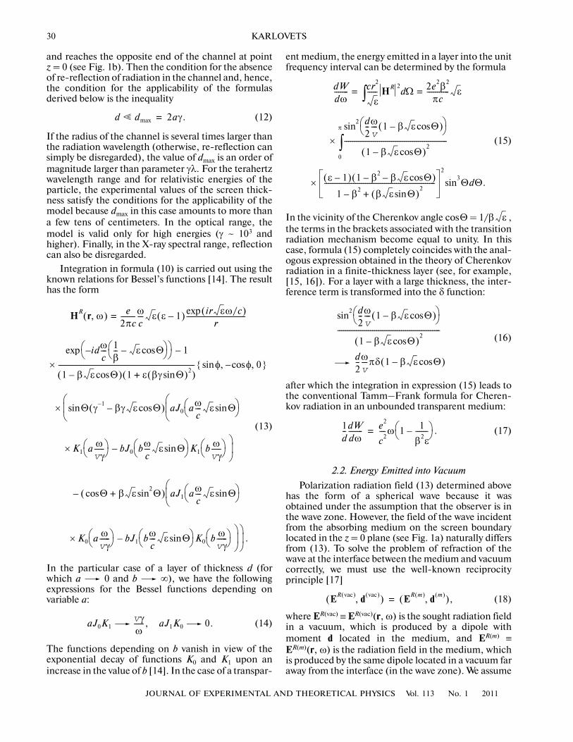
Let us consider radiation generated during uniformrectilinear motion of a charged particle along the axisof a cylindrical vacuum channel of radius a in a screenof thickness d and outer radius b (see Fig. 1a). Todetermine the radiation field, we must evaluate thevolume integral in expression (7), in which the field ofthe particle is defined by the well�known expression(see, for example, [12])
(9)
Hpol HR≈ ε iω
c2����� ir εω/c( )exp
r�����������������������������e=
× σ ω( )E0 r ' ω,( ) ik– r '⋅( )exp d3r ',
VT
∫
ε
Epol ER≈ 1
ε�����e– HR
.×=
E0 r ω,( ) eω
πv2γ����������=
× ρ
ρ��K1
ωρvγ������ i
� vv
���K0ωρvγ������–⎝ ⎠
⎛ ⎞ iωv
���z⎝ ⎠⎛ ⎞ ,exp
where ρ = {x, y} and K0, K1 are modified Bessel’s func�tions of the second kind. For the magnetic field ofradiation, we have
(10)
where the unit vector of radiation in the medium hasthe form
(11)
It should be emphasized that the polarization radi�ation field obtained in this way does not contain infor�mation on possible reflections of waves from theboundaries of the substance itself or on possible re�reflections of waves in the vacuum channel. Re�reflec�tion of waves in the substance can be taken intoaccount (see Section 3), but allowance for re�reflec�tion of waves in the vacuum channel is impossible inthe given approach. If, however, we confine our analy�sis to the case of not too low energies of the particle(β � 1), this constraint is substantial only for largethicknesses of the screen because Cherenkov radiationis known to be unable to enter into the vacuum fromthe medium through the plane parallel to the velocityvector of the particle (total internal reflection; see [13]and Section 4 below), while diffraction radiationpropagates at small angles θ ~ γ–1 � 1 in the relativisticcase. To derive a quantitative condition, we assumethat the wave is emitted at angle θ = γ–1 at point z = ⎯d
HR r ω,( ) eω2 ε 1–( )
4π2v
2cγ��������������������� ir εω/c( )exp
r�����������������������������k=
× ρ ' ρ ' φ ' z ' ρ 'ρ '���K1
ωρ 'vγ
�������⎝⎛d
d–
0
∫d
0
2π
∫d
a
b
∫
– iγ�� vv
���K0ωρ 'vγ
������� ⎠⎞ ik– r '⋅ iω
v
���z '+⎝ ⎠⎛ ⎞ ,exp
e Θ φcossin Θ φsinsin Θcos, ,{ }.=
Fig. 1. (a) Diagram of generation of polarization radiation by a charged particle moving in a cylindrical channel. (b) Determina�tion of the applicability boundaries of the model; PR is polarization radiation, and DR is diffraction radiation.
(a) (b)
ε(ω)
b
d
ae
v 2a
DR
dmax
0 z
Θ
θ
θ = γ−1
PR
30
JOURNAL OF EXPERIMENTAL AND THEORETICAL PHYSICS Vol. 113 No. 1 2011
KARLOVETS
and reaches the opposite end of the channel at pointz = 0 (see Fig. 1b). Then the condition for the absenceof re�reflection of radiation in the channel and, hence,the condition for the applicability of the formulasderived below is the inequality
(12)
If the radius of the channel is several times larger thanthe radiation wavelength (otherwise, re�reflection cansimply be disregarded), the value of dmax is an order ofmagnitude larger than parameter γλ. For the terahertzwavelength range and for relativistic energies of theparticle, the experimental values of the screen thick�ness satisfy the conditions for the applicability of themodel because dmax in this case amounts to more thana few tens of centimeters. In the optical range, themodel is valid only for high energies (γ ~ 103 andhigher). Finally, in the X�ray spectral range, reflectioncan also be disregarded.
Integration in formula (10) is carried out using theknown relations for Bessel’s functions [14]. The resulthas the form
(13)
In the particular case of a layer of thickness d (forwhich a 0 and b ∞), we have the followingexpressions for the Bessel functions depending onvariable a:
(14)
The functions depending on b vanish in view of theexponential decay of functions K0 and K1 upon anincrease in the value of b [14]. In the case of a transpar�
d � dmax 2aγ.=
HR r ω,( ) e2πc�������ω
c��� ε ε 1–( ) ir εω/c( )exp
r�����������������������������=
×idω
c��� 1
β�� ε Θcos–⎝ ⎠
⎛ ⎞–⎝ ⎠⎛ ⎞exp 1–
1 β ε Θcos–( ) 1 ε βγ Θsin( )2+( )������������������������������������������������������������������ φsin φcos– 0, ,{ }
× Θ γ 1– βγ ε Θcos–( ) aJ0 aωc��� ε Θsin⎝ ⎠
⎛ ⎞⎝⎜⎛
sin⎝⎜⎛
× K1 a ωvγ�����⎝ ⎠
⎛ ⎞ bJ0 bωc��� ε Θsin⎝ ⎠
⎛ ⎞ K1 b ωvγ�����⎝ ⎠
⎛ ⎞⎠⎟⎞
–
– Θcos β ε Θsin2
+( ) aJ1 aωc��� ε Θsin⎝ ⎠
⎛ ⎞⎝⎜⎛
× K0 a ωvγ�����⎝ ⎠
⎛ ⎞ bJ1 bωc��� ε Θsin⎝ ⎠
⎛ ⎞ K0 b ωvγ�����⎝ ⎠
⎛ ⎞⎠⎟⎞
⎠⎟⎞
.–
aJ0K1vγω�����, aJ1K0 0.
ent medium, the energy emitted in a layer into the unitfrequency interval can be determined by the formula
(15)
In the vicinity of the Cherenkov angle cosΘ = 1/β ,the terms in the brackets associated with the transitionradiation mechanism become equal to unity. In thiscase, formula (15) completely coincides with the anal�ogous expression obtained in the theory of Cherenkovradiation in a finite�thickness layer (see, for example,[15, 16]). For a layer with a large thickness, the inter�ference term is transformed into the δ function:
(16)
after which the integration in expression (15) leads tothe conventional Tamm–Frank formula for Cheren�kov radiation in an unbounded transparent medium:
(17)
2.2. Energy Emitted into Vacuum
Polarization radiation field (13) determined abovehas the form of a spherical wave because it wasobtained under the assumption that the observer is inthe wave zone. However, the field of the wave incidentfrom the absorbing medium on the screen boundarylocated in the z = 0 plane (see Fig. 1a) naturally differsfrom (13). To solve the problem of refraction of thewave at the interface between the medium and vacuumcorrectly, we must use the well�known reciprocityprinciple [17]
(18)
where ER(vac) ≡ ER(vac)(r, ω) is the sought radiation fieldin a vacuum, which is produced by a dipole withmoment d located in the medium, and ER(m) ≡ER(m)(r, ω) is the radiation field in the medium, whichis produced by the same dipole located in a vacuum faraway from the interface (in the wave zone). We assume
dWdω������� cr2
���� HR 2
Ωd∫2e2β2
πc����������� ε= =
×
d2��ωv
��� 1 β ε Θcos–( )⎝ ⎠⎛ ⎞sin
2
1 β ε Θcos–( )2
��������������������������������������������������
0
π
∫
× ε 1–( ) 1 β2– β ε Θcos–( )
1 β2– β ε Θsin( )2
+������������������������������������������������������
2
ΘdΘ.sin3
ε
d2��ωv
��� 1 β ε Θcos–( )⎝ ⎠⎛ ⎞sin
2
1 β ε Θcos–( )2
��������������������������������������������������
d2��ωv
���πδ 1 β ε Θcos–( )
1d��dW
dω������� e2
c2���ω 1 1
β2ε������–⎝ ⎠
⎛ ⎞ .=
ER vac( ) d vac( ),( ) ER m( ) d m( ),( ),=
JOURNAL OF EXPERIMENTAL AND THEORETICAL PHYSICS Vol. 113 No. 1 2011
ON THE THEORY OF POLARIZATION RADIATION 31
that dipole moment d is oriented along the normal tothe surface through which radiation emerges (i.e., alongthe z axis in our case). Physically, such an orientationmeans that a thin conducting screen at large distancescan be treated as a double layer. Taking into account thefact that vector ER is perpendicular to e, we can find themodulus of the radiation field in a vacuum from for�mula (18):
(19)
Here, we have used the Snell law connecting “vac�uum” angle θ and angle Θ in the medium, as well asthe fact that the following equality holds for the field ofa spherical wave in the medium:
The relations between the angles at which radiation isemitted in the medium and in the vacuum, whichappear in formula (13), can be expressed as follows:
(20)
Then, in accordance with formula (19), we mustfind the magnetic field in the medium in the case whenthe field of the wave incident from vacuum on theinterface can be expressed in terms of field (13); i.e.,we must solve the inverse problem. In the case of con�ducting medium, we can confine our analysis to con�ventional Fresnel laws for one interface (i.e., we disre�gard the waves reflected in the substance from the sec�ond boundary of the screen, which lies in the z = –dplane). Such an algorithm was used in our previouspublication [18]. In the general case, the field incidenton the interface is not equal to “forward” radiation(13) because the “backward” radiation waves propa�gating at angles Θ > π/2 can also emerge into the vac�uum through the front face of the plate after theirreflection from the rear face. In addition, refraction ofthe wave incident from the vacuum into the screenshould be considered taking into account possiblemultiple re�reflections. Here, an important stipulationconcerning the screen thickness d under investigationis due. If the size of the region through which radiationemerges into vacuum is much larger than the screenthickness (thin screen), and the medium has a non�zero absorbance, the waves reflected from the upperand lower faces of the plate can be disregarded.Indeed, if the inequality b – a � d holds, only thewaves of Cherenkov radiation with Θ ≈ π/2 are inci�dent on the upper and lower faces of the screen, whichcorresponds to ε' � 1. It was mentioned above that
ER vac( ) Θsinθsin
����������ER m( )=
= 1
����ER m( ) 1
�HR m( )
.=
ER m( ) ε 1/2– HR m( )
.=
e 1
ε����� θ φcossin θ φsinsin ε θsin
2–, ,
⎩ ⎭⎨ ⎬⎧ ⎫
.=
such waves experience total internal reflection and canemerge into the vacuum through the front face of theplate at angles Θ ≈ π/2. We will consider this questionagain in Section 5.
On account of the above arguments, we assume thatthe wave incident on the interface consists of the fieldof “forward” radiation (13), which will be denotedbelow by index (F), as well as the field of “backward”radiation reflected from the rear face of the screen inthe z = –d plane (index (B)). The backward radiationfield can be determined from formula (13) as usual bythe inversion of the z projection of the wavevector or by
the substitution ⎯ . Whenquantities in relation (19) are squared, expression
must be written as the sum of the squaredmoduli of the field components, one of which is per�pendicular to the plane of incidence of the wave on theinterface, and the other lies in the plane of incidence.Considering that the magnetic field component lyingin the plane of incidence is connected with the electricfield component perpendicular to the plane of inci�
dence via , we finally obtain the following relationsfor the energy emitted into the vacuum (into half�space z > 0):
(21)
It should be noted that when wave (13) is incidentfrom the vacuum, the amplitude of the spherical wave
must be taken without factor in the exponential. Inexpression (21), the magnetic field component lying inthe incidence plane in the coordinate system used herehas the form
(22)
while the magnetic field component perpendicular tothe incidence plane has the form
(23)
Formula (21) contains coefficients RH, E of reflectionfrom the boundary z = –d for waves whose magnetic orelectric field is perpendicular to the plane of inci�dence:
ε θsin2
– ε θsin2
–
HR m( ) 2
ε
d2WdωdΩ������������� cr2 ER vac( ) 2 d2W
dωdΩ�������������
⊥
d2WdωdΩ�������������
||
+= =
= cr2
ε 2������ fH
2 H⊥ F( )
R RHH⊥ B( )
R+2
(
+ εfE2
H|| F( )
R REH|| B( )
R+2).
ε
H|| F B,( )
R Hz F B,( )
R( )2
Hx F B,( )
R φcos(+(=
+ Hy F B,( )
R φsin )2)
1/2,
H⊥ F B,( )
R Hy F B,( )
R φcos Hx F B,( )
R φ.sin–=
RHε θsin
2– ε θcos–
ε θsin2
– ε θcos+��������������������������������������=
32
JOURNAL OF EXPERIMENTAL AND THEORETICAL PHYSICS Vol. 113 No. 1 2011
KARLOVETS
(24)
as well as Fresnel coefficients fH and fE connecting theamplitude of the wave incident on the surface of theplate from the vacuum with the amplitude of the wavetransmitted through the plate with allowance for mul�tiple re�reflections inside it. These coefficients caneasily be calculated using the standard boundary con�ditions in complete analogy with the case of a singleinterface (see, for example, [16, 17]). We give theseexpressions without derivation:
(25)
For thick screens, these coefficients are transformedinto the conventional expressions for a single interface(in this case, ε'' ≠ 0).
Returning to the orientation of the emitting dipolein formula (18), we note that if the d component par�allel to the plane through which radiation emergesexisted, formula (19) would acquire a term propor�tional to
and containing an additional power in the numer�ator. This would ultimately turn the radiation intensityto infinity in the limit of a perfect conductivity of thescreen (ε'' ∞).
It can easily be seen that = 0 in the azi�muthally symmetric problem, and we obtain, aftercollecting terms, the following expression for theenergy emitted into vacuum in the forward direction(θ < π/2):
(26)
× i2dωc��� ε θsin
2–⎝ ⎠
⎛ ⎞ ,exp
REε θsin
2– θcos–
ε θsin2
– θcos+������������������������������������=
× i2dωc��� ε θsin
2–⎝ ⎠
⎛ ⎞ ,exp
fH 2ε θ ε θsin2
– ε θcos+( )cos=
× idωc��� ε θsin
2––⎝ ⎠
⎛ ⎞exp
× ε θcos ε θsin2
–+( )2
idωc��� ε θsin
2––⎝ ⎠
⎛ ⎞exp⎩⎨⎧
– ε θcos ε θsin2
––( )2
idωc��� ε θsin
2–⎝ ⎠
⎛ ⎞exp⎭⎬⎫
1–
,
fE 2 θ ε θsin2
– θcos+( )cos=
× idωc��� ε θsin
2––⎝ ⎠
⎛ ⎞exp
× θcos ε θsin2
–+( )2
idωc��� ε θsin
2––⎝ ⎠
⎛ ⎞exp⎩⎨⎧
– θcos ε θsin2
––( )2
idωc��� ε θsin
2–⎝ ⎠
⎛ ⎞exp⎭⎬⎫
1–
.
Θcosθcos
���������� ε θsin2
–
ε���������������������∝
ε
H || F B,( )
R
d2WdωdΩ�������������
F
e2
π2c������ β2 θcos
2
1 β2 θcos2
–( )2
����������������������������� ωvγ�����⎝ ⎠
⎛ ⎞2
=
× ε 1–( ) 1 β2 ε θsin2
–( )–( )1–
ε θcos ε θsin2
–+( )2
idωc��� ε θsin
2––⎝ ⎠
⎛ ⎞exp ε θcos ε θsin2
––( )2
idωc��� ε θsin
2–⎝ ⎠
⎛ ⎞exp–
������������������������������������������������������������������������������������������������������������������������������������������������������������������������������������2
× ε θsin2
– ε θcos–( ) 1 β ε θsin2
––( ) θ 1 β2– β ε θsin2
–+( )sin ζ1(
– γ 1– β θsin2 ε θsin
2––( )ζ2 ) idω
c��� ε θsin
2–⎝ ⎠
⎛ ⎞exp ε θsin2
– ε θcos+( ) 1 β ε θsin2
–+( )+
× θ 1 β2– β ε θsin2
––( )ζ1 γ 1– β θsin2 ε θsin
2–+( )ζ2–sin( ) idω
c��� ε θsin
2––⎝ ⎠
⎛ ⎞exp
– 2 ε θsin2
– θ 1 β2– β2 ε θsin2
–( )– β3ε θcos–( )ζ1sin(
– γ 1– ε β θcos β2 θ θcossin2
+ +( )ζ2 ) iωv
���d–⎝ ⎠⎛ ⎞
2
.exp
JOURNAL OF EXPERIMENTAL AND THEORETICAL PHYSICS Vol. 113 No. 1 2011
ON THE THEORY OF POLARIZATION RADIATION 33
Here, the following notation has been introduced:
(27)
It should be noted from the very outset that in thelimiting case of transition radiation in a plate of thick�ness d (for which a 0, b ∞), functions ζ1 and
ζ2 have values vγ/ω and 0. In this case, formula (26)completely coincides with the well�known Pafomovsolution [2, 19–21] (pay attention to the obvious mis�print in formula (3.55) from [19], which does notappear in [2, 20, 21]). For thick screens, the solutionobtained in this way is transformed into the well�known Ginzburg–Frank formula for transition radia�tion from a semi�infinite medium.
The pole 0 in the denomina�tor of expression (26) corresponds to the condition forCherenkov radiation in a vacuum. However, this polecan be eliminated, and in the vicinity of Cherenkovangle θChR, formula (26) under the assumption of atransparent medium assumes the form
(28)
Since
the quantities in the radicand are always positive.A distinguishing feature of formula (26) is that the
energy emitted in the backward direction (θ > π/2)cannot be obtained by simple substitution β –β.Indeed, for radiation emerging from the rear face ofthe screen, we must change the places of indices (F)and (B) in formula (21), which leads to the substitu�tion
in the first two terms in formula (26), as well as thesubstitution
The latter substitution breaks the symmetry observedin the limiting case of transition radiation. Simple signreversal of the particle velocity in formula (26) isimpossible if only in view of the fact that, in this for�mula, as well as in the initial expression (9) for the par�ticle field, the velocity appears in the argument of theBessel function and is a positive quantity.
It is convenient to calculate the energy emitted inthe backward direction in the same coordinate system(as before, θ < π/2 in this case) by changing the direc�tion of the particle velocity, which leads to sign reversalof the z component of the particle field (9), as well asto the substitution z –z in the exponent. Analo�gous calculations lead to the following expression:
(29)
ζ1 aJ0 aωc��� θsin⎝ ⎠
⎛ ⎞ K1 a ωvγ�����⎝ ⎠
⎛ ⎞=
– bJ0 bωc��� θsin⎝ ⎠
⎛ ⎞ K1 b ωvγ�����⎝ ⎠
⎛ ⎞ ,
ζ2 aJ1 aωc��� θsin⎝ ⎠
⎛ ⎞ K0 a ωvγ�����⎝ ⎠
⎛ ⎞=
– bJ1 bωc��� θsin⎝ ⎠
⎛ ⎞ K0 b ωvγ�����⎝ ⎠
⎛ ⎞ .1 β ε θsin
2––
d2WdωdΩ�������������
F
d2WdωdΩ�������������
ChR
e2ω2c3
4π2γ2v
6���������������� 1 β2 εβ2–+( )=
×1 ε 1 β2 εβ2–+–( ) ζ1 2 β2–( ) β2ε 1– ζ2γ 1– 2 β2ε–( )+( )
1 ε 1 β2 εβ2–+–( )2
1 ε 1 β2 εβ2–++( )2
i2dω/v–( )exp–�������������������������������������������������������������������������������������������������������������������������
⎝ ⎠⎜ ⎟⎛ ⎞
2
.
θChRsin ε 1/β2– 1,<=
β ε θsin2
– β ε θsin2
– ,–
β θsin2 ε θsin
2– β θsin
2– ε θsin
2– .+
d2WdωdΩ�������������
B
e2
π2c������ β2 θcos
2
1 β2 θcos2
–( )2
����������������������������� ωvγ�����⎝ ⎠
⎛ ⎞2
=
× ε 1–( ) 1 β2 ε θsin2
–( )–( )1–
ε θcos ε θsin2
–+( )2
idωc��� ε θsin
2––⎝ ⎠
⎛ ⎞exp ε θcos ε θsin2
––( )2
idωc��� ε θsin
2–⎝ ⎠
⎛ ⎞exp–
������������������������������������������������������������������������������������������������������������������������������������������������������������������������������������2
× ε θsin2
– ε θcos–( ) 1 β ε θsin2
–+( ) θ 1 β2– β ε θsin2
––( )sin ζ1(
– γ 1– β θsin2 ε θsin
2–+( )ζ2 ) idω
c��� ε θsin
2–⎝ ⎠
⎛ ⎞exp ε θsin2
– ε θcos+( ) 1 β ε θsin2
––( )+
34
JOURNAL OF EXPERIMENTAL AND THEORETICAL PHYSICS Vol. 113 No. 1 2011
KARLOVETS
× θ 1 β2– β ε θsin2
–+( )ζ1 γ 1– β θsin2 ε θsin
2––( )ζ2–sin( ) idω
c��� ε θsin
2––⎝ ⎠
⎛ ⎞exp
– 2 ε θsin2
– θ 1 β2– β2 ε θsin2
–( )– β3ε θcos+( )ζ1sin(
– γ 1– ε β θcos– β2 θ θcossin2
–( )ζ2 ) iωv
���d⎝ ⎠⎛ ⎞
2
.exp
It can be seen that formulas (26) and (29) are trans�formed into each other under the substitutions (every�where except in exponents)
(30)
Expression (29) for the intensity of backward radiationis distinguished by the presence of the “Cherenkov”pole
which does not appear for transition radiation in thebackward direction in a semi�infinite medium. This isdue to the fact that radiation emitted in the directionof the particle velocity can be reflected from the frontface of the screen and emerge into the vacuum thoughthe rear face.
In the particular case of ideal conductivity (ε'' ∞), the dependence on screen thickness d disappears(skin effect), and we have the following expression for
ε θsin2
– ε θsin2
– , θ θ,cos–cos–
iωv
���d–⎝ ⎠⎛ ⎞ iω
v
���d⎝ ⎠⎛ ⎞ .expexp
1 β ε θsin2
–– 0,
diffraction radiation from a circular aperture in aninfinitely thin screen of a finite radius:
(31)
the energy emitted in both directions is the same. Thissolution coincides with the solution obtained earlier in[3] using another method and (in the ultrarelativisticcase) with the results obtained in [9, 22–24], wherethe problem was solved in the ultrarelativistic limit.Since the dependence on the screen thickness has dis�appeared, formula (31) is also valid for a nonrelativis�tic charge if radiation losses can still be regarded assmall as compared to the total energy of the particle.
It should be emphasized that analysis of radiationemerging from the screen into a vacuum through thez = 0 plane corresponds to a small screen thicknessand, accordingly, to the emergence of the skin effectfor ε'' � 1 exactly in the vicinity of this plane. For thisreason, the transition to radiation in a perfectly con�ducting waveguide, as well as the transition to Cheren�kov radiation in an infinitely long channel, cannot bemade using the above formulas.
3. POLARIZATION RADIATIONFROM A RECTANGULAR SCREEN
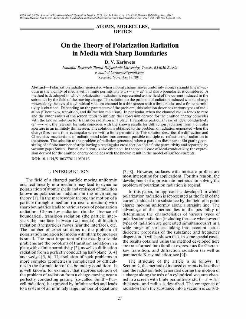
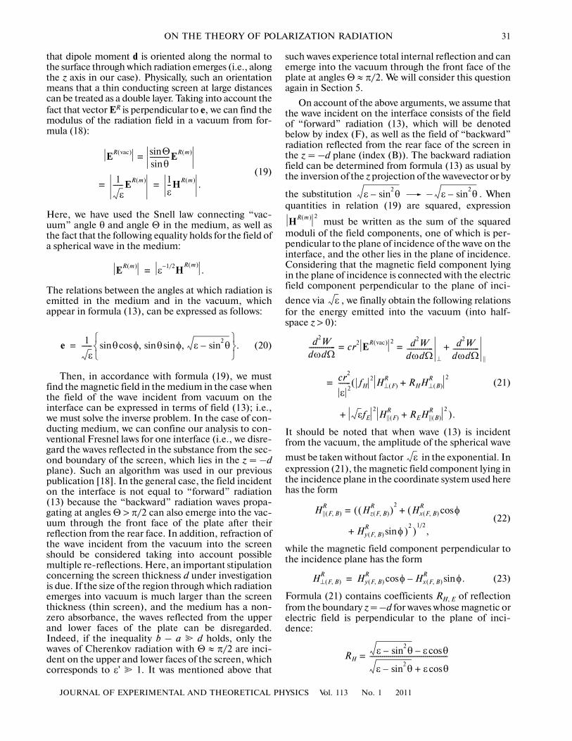
In the case of azimuthal symmetry of the problem,the terms with coefficient fE make zero contribution togeneral expression (21) for the emitted energy becausethe magnetic field is polarized perpendicularly to theplane of incidence. If polarization radiation is gener�ated by a particle moving near a rectangular screen(see Fig. 2), this circumstance does not take placebecause the azimuthal symmetry is broken. In thecoordinate system used here, the magnetic field com�ponents of radiation have the form
(32)
d2WdωdΩ�������������
F
d2WdωdΩ�������������
B
e2
π2c������= =
× β2 θsin2
1 β2 θcos2
–( )2
����������������������������� ωvγ�����⎝ ⎠
⎛ ⎞2
ζ1ζ2
βγ θsin��������������+⎝ ⎠
⎛ ⎞2
,
H⊥ F B,( )
R Hx F B,( )
R φcos Hy F B,( )
R φ,sin–=
H|| F B,( )
R Hz F B,( )
R( )2
Hx F B,( )
R φsin(+(=
+ Hy F B,( )
R φcos )2)
1/2.
e
a
d
y
h0
V
ε(ω)
θ
φ
z
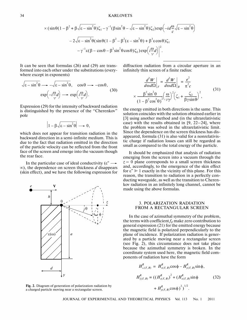
Fig. 2. Diagram of generation of polarization radiation bya charged particle moving near a rectangular screen.
JOURNAL OF EXPERIMENTAL AND THEORETICAL PHYSICS Vol. 113 No. 1 2011
ON THE THEORY OF POLARIZATION RADIATION 35
To find the radiation field, we take advantage of thefact that the screen width along the x axis is infinitelylarge. Then formula (7) gives
(33)
The corresponding Fourier component of the fieldproduced by the charge has the form
(34)
Here, h is the distance between the particle trajectoryand the screen, and unit vector e of radiation in the“vacuum” variables has the form
(35)
Substituting expression (34) into (33) and (32), weobtain the field components of radiation:
(36)
The upper sign in these expressions corresponds to forward radiation and the lower sign, to backward radiation.In raising these expressions to the second power, we can use the relation
(37)
HR r ω,( ) 2πiω
c2���������� ε ir εω/c( )exp
r�����������������������������e=
× z ' y 'σ ω( )E0 kx y ' z ' ω, , ,( )d
0
a
∫d
d–
0
∫
× ikyy '– ikzz '–( ).exp
E0 kx y ' z' ω, , ,( ) ie–2πv�������� iωz '/v( )exp
1 ε βγex( )2+����������������������������=
× εβγex i 1 ε βγex( )2+ γ 1–, ,⎩ ⎭⎨ ⎬⎧ ⎫
× y ' h+( ) ωvγ����� 1 ε βγex( )2+–⎝ ⎠
⎛ ⎞ .exp
e 1
ε����� θ φsinsin θ φcossin ε θsin
2–, ,
⎩ ⎭⎨ ⎬⎧ ⎫
.=
H⊥ F B,( )
R eπc�����βγ
4����� ε 1–( ) ir εω/c( )exp
r�����������������������������
1 idωc��� 1
β��– ε θsin
2–±⎝ ⎠
⎛ ⎞⎩ ⎭⎨ ⎬⎧ ⎫
exp–
1 β ε θsin2
–+−������������������������������������������������������������������=
× h ωvγ����� 1 βγ θ φsinsin( )2+–⎝ ⎠
⎛ ⎞
a ωvγ����� iβγ θ φcossin 1 βγ θsin φsin( )2++( )–
⎩ ⎭⎨ ⎬⎧ ⎫
exp 1–
1 βγ θ φsinsin( )2+ iβγ θ φcossin 1 βγ θ φsinsin( )2++( )��������������������������������������������������������������������������������������������������������������������exp
× γ 1– θsin ε θsin2
– i φ 1 βγ θ φsinsin( )2+cos βγ θ φsin2
sin+( )+−( ),
H|| F B,( )
R eπc�����βγ
4����� ε 1–( ) ir εω/c( )exp
r�����������������������������
1 idωc��� 1
β��– ε θsin
2–±⎝ ⎠
⎛ ⎞⎩ ⎭⎨ ⎬⎧ ⎫
exp–
1 β ε θsin2
–+−������������������������������������������������������������������=
× h ωvγ����� 1 βγ θ φsinsin( )2+–⎝ ⎠
⎛ ⎞exp
×
a ωvγ����� iβγ θ φcossin 1 βγ θ φsinsin( )2++( )–
⎩ ⎭⎨ ⎬⎧ ⎫
exp 1–
1 βγ θ φsinsin( )2+ iβγ θ φcossin 1 βγ θ φsinsin( )2++( )��������������������������������������������������������������������������������������������������������������������
× ε φ βγ θ φcossin i 1 βγ θ φsinsin( )2+–( ).sin
a ωvγ����� iβγ θ φcossin 1 βγ θ φsinsin( )2++( )–
⎩ ⎭⎨ ⎬⎧ ⎫
exp 1–2
= 4 a2�� ωvγ����� 1 βγ θ φsinsin( )2+⎝ ⎠
⎛ ⎞sinh2 a
2��ω
c��� θ φcossin⎝ ⎠
⎛ ⎞sin2
+⎝ ⎠⎛ ⎞ a ω
vγ����� 1 βγ θ φsinsin( )2+–⎝ ⎠
⎛ ⎞ .exp
36
JOURNAL OF EXPERIMENTAL AND THEORETICAL PHYSICS Vol. 113 No. 1 2011
KARLOVETS
Substituting expressions (36) into (21) and collect�ing terms for forward radiation, we obtain
(38)
d2WdωdΩ�������������
⊥ F( )
e2
π2c������ β2 θcos
2
1 β2 θcos2
–( ) 1 βγ θ φsinsin( )2+( )��������������������������������������������������������������������=
× ωvγ�����a
2�� 1 βγ θ φsinsin( )2+⎝ ⎠
⎛ ⎞sinh2
⎝⎛
+ ωc���a
2�� θ φcossin⎝ ⎠
⎛ ⎞⎠⎞ ε 1–
1 β2 ε θsin2
–( )–���������������������������������
2sin
2
× h a2��+⎝ ⎠
⎛ ⎞ 2ωvγ������ 1 βγ θ φsinsin( )2+–
⎩ ⎭⎨ ⎬⎧ ⎫
exp
× ε θcos ε θsin2
–+( )2
idωc��� ε θsin
2––⎝ ⎠
⎛ ⎞exp
– ε θcos ε θsin2
––( )2
idωc��� ε θsin
2–⎝ ⎠
⎛ ⎞exp2–
× ε θsin2
– ε θcos–( ) 1 β ε θsin2
––( ) �
× γ 1– θsin ε θsin2
– βγ θ φsin2
sin(+(
+ i φ 1 βγ θ φsinsin( )2+cos ) )
× idωc��� ε θsin
2–⎝ ⎠
⎛ ⎞exp
+ ε θsin2
– ε θcos+( ) 1 β ε θsin2
–+( )
× γ 1– θsin ε θsin2
– βγ θ φsin2
sin(–(
+ i φ 1 βγ θ φsinsin( )2+ ) )cos
× idωc��� ε θsin
2––⎝ ⎠
⎛ ⎞exp 2 ε θsin2
––
× γ 1– θ 1 βε θcos+( )sin ε θcos β ε θsin2
–( )+( )–[
× βγ θ φsin2
sin i φ 1 βγ θ φsinsin( )2+cos+( ) ]
× iωv
���d–⎝ ⎠⎛ ⎞exp
2
,
d2WdωdΩ�������������
|| F( )
e2
π2c������ βγ θ φsincos( )2
1 βγ θ φsinsin( )2+�������������������������������������=
× ωvγ�����a
2�� 1 βγ θ φsinsin( )2+⎝ ⎠
⎛ ⎞sinh2
⎝⎛
The total intensity is given by the sum of the aboveexpressions. It should be noted that the decompositionof the spectral–angular density into components usedhere is determined by the polarization characteristicsof the magnetic field of radiation (and not by the elec�tric field, as is often used; see, for example, [2]).
A distinguishing feature of the above expressions isallowance for possible multiple re�reflections of radia�tion inside the screen. In the case of a conductingscreen, the contribution from radiation reflected fromthe rear face of the plate is small, and the formuladerived for such a screen coincides with that obtained in[18]. It should also be noted that the resultant formula
contains the Cherenkov pole 0,which can be eliminated for a finite width d of thescreen.
It should be emphasized that, to obtain a formulafor backward radiation, it is insufficient to changeplaces of the corresponding fields in expression (21)because in this case we consider the emergence ofradiation into vacuum through the z = –d plane andnot through the plane z = 0. To obtain the correctresult, we must also change the direction of the parti�
+ ωc���a
2�� θ φcossin⎝ ⎠
⎛ ⎞⎠⎞ ε 1–
1 β2 ε θsin2
–( )–���������������������������������
2sin
2
× h a2��+⎝ ⎠
⎛ ⎞ 2ωvγ������ 1 βγ θ φsinsin( )2+–
⎩ ⎭⎨ ⎬⎧ ⎫
exp
× θcos ε θsin2
–+( )2
idωc��� ε θsin
2––⎝ ⎠
⎛ ⎞exp
– θcos ε θsin2
––( )2
idωc��� ε θsin
2–⎝ ⎠
⎛ ⎞exp2–
× ε θsin2
– θcos–( ) 1 β ε θsin2
––( )
× idωc��� ε θsin
2–⎝ ⎠
⎛ ⎞exp
+ ε θsin2
– θcos+( ) 1 β ε θsin2
–+( )
× idωc��� ε θsin
2––⎝ ⎠
⎛ ⎞exp
– 2 ε θsin2
– 1 β θcos+( ) iωv
���d–⎝ ⎠⎛ ⎞exp
2
.
1 β ε θsin2
––
JOURNAL OF EXPERIMENTAL AND THEORETICAL PHYSICS Vol. 113 No. 1 2011
ON THE THEORY OF POLARIZATION RADIATION 37
cle velocity, which corresponds to sign reversal for thez component and the substitution
in formula (34). In this case, the backward radiationfield propagating in the positive direction of the z axisdiffers from formula (36) in the substitution
in the exponent. Taking into account these arguments,we obtain the following expression for the energyemitted in the backward direction (as before, θ < π/2):
(39)
iωv
���z '⎝ ⎠⎛ ⎞ iω
v
���z '–⎝ ⎠⎛ ⎞expexp
1β��– ε θsin
2– 1
β��– ε θsin
2–+
d2WdωdΩ�������������
⊥ B( )
e2
π2c������ β2 θcos
2
1 β2 θcos2
–( ) 1 βγ θ φsinsin( )2+( )��������������������������������������������������������������������=
× ωvγ�����a
2�� 1 βγ θ φsinsin( )2+⎝ ⎠
⎛ ⎞sinh2
⎝⎛
+ ωc���a
2�� θ φcossin⎝ ⎠
⎛ ⎞⎠⎞ ε 1–
1 β2 ε θsin2
–( )–���������������������������������
2sin
2
× h a2��+⎝ ⎠
⎛ ⎞ 2ωvγ������ 1 βγ θ φsinsin( )2+–
⎩ ⎭⎨ ⎬⎧ ⎫
exp
× ε θcos ε θsin2
–+( )2
idωc��� ε θsin
2––⎝ ⎠
⎛ ⎞exp
– ε θcos ε θsin2
––( )2
idωc��� ε θsin
2–⎝ ⎠
⎛ ⎞exp2–
× ε θsin2
– ε θcos–( ) 1 β ε θsin2
–+( )
× γ 1– θsin ε θsin2
– βγ θ φsin2
sin(–(
+ i φ 1 βγ θ φsinsin( )2+ ) ) idωc��� ε θsin
2–⎝ ⎠
⎛ ⎞expcos
+ ε θsin2
– ε θcos+( ) 1 β ε θsin2
––( )
× γ 1– θsin ε θsin2
– βγ θ φsin2
sin(+(
+ i φ 1 βγ θ φsinsin( )2+ ) )cos
× idωc��� ε θsin
2––⎝ ⎠
⎛ ⎞exp
– 2 ε θsin2
– γ 1– θ 1 βε θcos–( )sin(
– ε θcos– β(ε θsin2
–+( ) ) βγ θ φsin2
sin(
It can easily be seen that formulas (38) and (39) aretransformed into each other upon substitution (30) aswell as upon the substitution β –β and cosφ ⎯cosφ, which corresponds to a shift in the azimuthalangle by π. This expression also contains the Cheren�
+ i φ 1 βγ θ φsinsin( )2+cos ) ) iωv
���d⎝ ⎠⎛ ⎞exp
2
,
d2WdωdΩ�������������
|| B( )
e2
π2c������ βγ θ φsincos( )2
1 βγ θ φsinsin( )2+�������������������������������������=
× ωvγ�����a
2�� 1 βγ θ φsinsin( )2+⎝ ⎠
⎛ ⎞sinh2
⎝⎛
+ ωc���a
2�� θ φcossin⎝ ⎠
⎛ ⎞⎠⎞ ε 1–
1 β2 ε θsin2
–( )–���������������������������������
2sin
2
× h a2��+⎝ ⎠
⎛ ⎞ 2ωvγ������ 1 βγ θ φsinsin( )2+–
⎩ ⎭⎨ ⎬⎧ ⎫
exp
× θcos ε θsin2
–+( )2
idωc��� ε θsin
2––⎝ ⎠
⎛ ⎞exp
– θcos ε θsin2
––( )2
idωc��� ε θsin
2–⎝ ⎠
⎛ ⎞exp2–
× ε θsin2
– θcos–( ) 1 β ε θsin2
–+( )
× idωc��� ε θsin
2–⎝ ⎠
⎛ ⎞exp
+ ε θsin2
– θcos+( ) 1 β ε θsin2
––( )
× idωc��� ε θsin
2––⎝ ⎠
⎛ ⎞exp
– 2 ε θsin2
– 1 β θcos–( ) iωv
���d⎝ ⎠⎛ ⎞exp
2
.
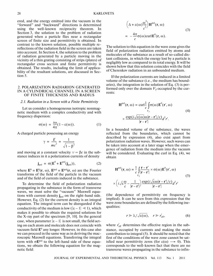
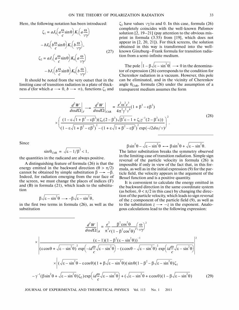
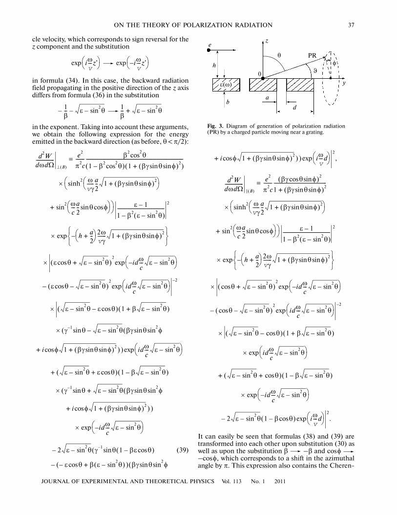
Fig. 3. Diagram of generation of polarization radiation(PR) by a charged particle moving near a grating.
ε(ω)
e
h
b
0
a
d
z
θ PR
y
φ
ϑ
38
JOURNAL OF EXPERIMENTAL AND THEORETICAL PHYSICS Vol. 113 No. 1 2011
KARLOVETS
kov pole associated with the contribution of wavesreflected from the front face of the screen and emerg�ing into the vacuum through the rear face.
In the special case of a perfectly conducting half�plane (ε'' ∞, a ∞), the energy emitted intoboth half�spaces is also the same and given by
(40)
which coincides with the result obtained in [3, 4] usinganother approach.
Comparison of the above formulas with the resultsobtained in the previous section shows that the lack ofazimuthal symmetry leads to the emergence of factor1 + (βγsinθsinφ)2 in the denominator of the formulasfor the emitted energy, which gives a radiation peak inthe vicinity of the yz plane perpendicular to the planeof the screen in the relativistic case for angles θ � γ–1
(i.e., in fact, for Cherenkov radiation) (see also [9,18]). In view of the absence of factor sin2θ in thenumerators of formulas (38) and (39), the peak in theangular distribution of diffraction radiation corre�sponds to angle θ = 0 as expected. The absence of the“Lorentz” term 1 – β2cos2θ in the denominator of theexpressions for the parallel component of intensityd2W/dωdΩ||| is also worth noting.
4. POLARIZATION RADIATION FROM A THIN GRATING OF A FINITE PERMITTIVITY
The method of induced currents used here can alsobe employed for calculating radiation emitted byatoms and molecules of a grating consisting of N stripswith a rectangular cross section and a finite permittiv�ity ε(ω) = ε' + iε'' under the action of the field of amoving particle (so�called Smith–Purcell radiation;see Fig. 3). To simplify calculations, we can require,analogously to the previous section, that thickness b ofthe strips be much smaller than the strip length d – a:
(41)where d is the grating period and a is the width of thevacuum gap between the strips. In this case, we canassume that radiation emerges into the vacuum onlythrough the upper or lower faces of the strips. Sincelarge emission angles ϑ are mainly of practical interestfor Smith—Purcell radiation, the thin�gratingapproximation employed here can be used for describ�ing actual experiments in the relevant field.
However, in the geometry considered here, in addi�tion to the thin�grating approximation, we mustrequire that the width of the vacuum gaps between the
d2WdωdΩ������������� e2
4π2c���������=
× 1 θ φsin2
sin2
– βγ θ φsinsin( )2 1 θcos2
+( )+{ }
× 1
1 β2 θcos2
–( ) 1 βγ θ φsinsin( )2+( )��������������������������������������������������������������������
× h2ωvγ������ 1 βγ θ φsinsin( )2+–⎝ ⎠
⎛ ⎞ ,exp
b � d a,–
strips be much smaller than the radiation wavelength.For a large number of periods N � 1, the radiationwavelength is rigidly connected with the lattice period(see below); therefore, for all angles ϑ far from zeroand π, this condition has the form
(42)
This condition stems from the fact that while multiplere�reflections of radiation in each strip can be gener�ally taken into account, re�reflections of radiation inthe vacuum gaps cannot be accounted for in the givenapproach. If, however, the strips are quite thin (b � d),allowance for multiple re�reflections of radiationbetween the strips would have led to corrections in therange of angles ϑ ~ b/d � 1 even if condition (42) wereviolated. For this reason, we will assume in furtheranalysis that the following inequalities are satisfied:
(43)
It will be clear from further analysis that condition (42)essentially leads to the representation of the radiationfield from the grating in the form of the vector sum ofthe radiation fields from each strip, which is obviouslytrue only when re�reflection of radiation between thestrips is ignored and for the angles satisfying inequali�ties (43). In the approach developed here and takinginto account the actual dielectric properties of thegrating, summation is performed for radiation fields inthe medium and not in the vacuum, which exactlycorresponds to small scattering of radiation from “par�ticles” with a size a � λ. Finally, formulas (21) for theradiation intensity, as well as formulas (25) for theFresnel coefficients derived for an infinitely largeplate, can be used only under conditions (41) and (42).This circumstance imposes substantial constraints onthe domain of applicability for a number of well�known models of radiation, in which calculations wereperformed from the very outset for a perfectly con�ducting grating (see Section 5 below).
Let us first consider radiation above the grating(i.e., in the half�space in which the charge moves). Itis convenient to solve the problem in variables θ, φused in the previous section (components of the unitvector of radiation are given in expression (35)). Atransition to variables ϑ, ϕ which are conventionallyused in the Smith–Purcell radiation geometry can bemade in the final formulas. The expression for therequired Fourier component of the field of the chargein the “vacuum” variables has the form
(44)
a � λ d.∼
π b/d– ϑ b/d.> >
E0 kx y ' z ' ω, , ,( ) ie–2πv�������� iωy '/v( )exp
1 βγ θ φsinsin( )2+����������������������������������������=
× βγ θ φsinsin γ 1– i 1 βγ θ φsinsin( )2+–, ,⎩ ⎭⎨ ⎬⎧ ⎫
× z ' h–( ) ωvγ����� 1 βγ θ φsinsin( )2+⎝ ⎠
⎛ ⎞ .exp
JOURNAL OF EXPERIMENTAL AND THEORETICAL PHYSICS Vol. 113 No. 1 2011
ON THE THEORY OF POLARIZATION RADIATION 39
Here, h is the distance between the particle trajec�tory and the grating. The radiation field in the grat�ing can be determined analogously to formula (33)(the grating width along the x axis is assumed to beinfinitely large), the only difference being that theintegration is carried out over the volume of all Nstrips. The field components required for calculat�ing the energy emitted into the vacuum are thendetermined using formulas (32). Taking intoaccount the well�known equality (calculation isperformed for an odd number of strips, but the finalformulas for the radiation intensity will also be
applicable for even values of N)
(45)
we obtain the magnetic field components of radiationin the form
(46)
Here, the upper sign corresponds to a wave propagatingin the positive direction of the z axis (subscript (F)),while the lower sign corresponds to the negative direc�tion (subscript (B)). The same notation as in the previ�ous sections is used for convenience. It can be seen fromthese formulas that the number of grating periodsappears only in the interference term of the formsin(Nx)/sinx, which corresponds to vector summation
of the radiation field from each strip. Substitution of theradiation field components into formula (21) for theintensity leads to the following expressions for radiationinto the upper half�space:
indωc��� β 1– θ φcossin–( )
⎩ ⎭⎨ ⎬⎧ ⎫
exp
m N 1–( )/2–=
N 1–( )/2
∑
=
Nd2��ω
c��� 1
β�� θ φcossin–⎝ ⎠
⎛ ⎞⎝ ⎠⎛ ⎞sin
d2��ω
c��� 1
β�� θ φcossin–⎝ ⎠
⎛ ⎞⎝ ⎠⎛ ⎞sin
�����������������������������������������������������
H⊥ F B,( )
R ie2πc�������βγ ε 1–( ) ir εω/c( )exp
r�����������������������������=
× i θ 1 βγ θ φsinsin( )2+sin ε θsin2
– γ 1– φcos βγ θ φsin2
sin+( )±⎝ ⎠⎛ ⎞
1 b ωvγ����� 1 βγ θ φsinsin( )2+ iβγ ε θsin
2–+−( )–
⎩ ⎭⎨ ⎬⎧ ⎫
exp–
1 βγ θ φsinsin( )2+ 1 βγ θ φsinsin( )2+ iβγ ε θsin2
–+−( )����������������������������������������������������������������������������������������������������������������������
×
d a–2
���������ωc��� 1
β�� θ φcossin–⎝ ⎠
⎛ ⎞⎝ ⎠⎛ ⎞sin
1 β θ φcossin–��������������������������������������������������������
×Nd
2��ω
c��� 1
β�� θ φcossin–⎝ ⎠
⎛ ⎞⎝ ⎠⎛ ⎞sin
d2��ω
c��� 1
β�� θ φcossin–⎝ ⎠
⎛ ⎞⎝ ⎠⎛ ⎞sin
����������������������������������������������������� h ωvγ����� 1 βγ θ φsinsin( )2+–⎝ ⎠
⎛ ⎞ ,exp
H|| F B,( )
R ie2πc�������βγ ε 1–( ) ir εω/c( )exp
r����������������������������� ε φ γ 1– βγ θ φcossin–( )sin=
×
1 b ωvγ����� 1 βγ θ φsinsin( )2+ iβγ ε θsin
2–+−( )–
⎩ ⎭⎨ ⎬⎧ ⎫
exp–
1 βγ θ φsinsin( )2+ 1 βγ θ φsinsin( )2+ iβγ ε θsin2
–+−( )����������������������������������������������������������������������������������������������������������������������
×
d a–2
���������ωc��� β 1– θ φcossin–( )⎝ ⎠
⎛ ⎞sin
1 β θ φcossin–�����������������������������������������������������������
Nd2��ω
c��� 1
β�� θ φcossin–⎝ ⎠
⎛ ⎞⎝ ⎠⎛ ⎞sin
d2��ω
c��� 1
β�� θ φcossin–⎝ ⎠
⎛ ⎞⎝ ⎠⎛ ⎞sin
����������������������������������������������������� h ωvγ����� 1 βγ θ φsinsin( )2+–⎝ ⎠
⎛ ⎞ .exp
d2WdωdΩ�������������
⊥ up( )
e2
π2c������ βγ( ) 2– θcos
2
1 βγ θ φsinsin( )2+�������������������������������������=
40
JOURNAL OF EXPERIMENTAL AND THEORETICAL PHYSICS Vol. 113 No. 1 2011
KARLOVETS
(47)
× ε 1–
ε θ φcossin( )2–��������������������������������
2
d a–2
���������ωc��� β 1– θ φcossin–( )⎝ ⎠
⎛ ⎞sin2
1 β θ φcossin–( )2�������������������������������������������������������������
×Nd
2��ω
c��� 1
β�� θ φcossin–⎝ ⎠
⎛ ⎞⎝ ⎠⎛ ⎞sin
2
d2��ω
c��� 1
β�� θ φcossin–⎝ ⎠
⎛ ⎞⎝ ⎠⎛ ⎞sin
2������������������������������������������������������
× h2ωvγ������ 1 βγ θ φsinsin( )2+–⎝ ⎠
⎛ ⎞exp
× ε θcos ε θsin2
–+( )2
ibωc��� ε θsin
2––⎝ ⎠
⎛ ⎞exp
– ε θcos ε θsin2
––( )2
ibωc��� ε θsin
2–⎝ ⎠
⎛ ⎞exp2–
× ε θsin2
– ε θcos–( )( 1 βγ θ φsinsin( )2+
– iβγ ε θsin2
– ) i θ 1 βγ θ φsinsin( )2+sin(
– ε θsin2
– γ 1– φcos βγ θ φsin2
sin+( ) )
× ibωc��� ε θsin
2–⎝ ⎠
⎛ ⎞exp ε θsin2
– ε θcos+( )+
× 1 βγ θ φsinsin( )2+ iβγ ε θsin2
–+( )
× i θ 1 βγ θ φsinsin( )2+sin(
+ ε θsin2
– γ 1– φcos βγ θ φsin2
sin+( ) )
× ibωc��� ε θsin
2––⎝ ⎠
⎛ ⎞exp
–2 ε θ(sin2
– iβ φ ε θsin2
–( )cos
+ i θ(1 ε βγ φsin( )+ 2sin )+ ε θ 1 βγ θ φsinsin( )2+cos
× γ 1– φcos βγ θ φcos2
sin–( ) )
× b ωvγ����� 1 βγ θ φsinsin( )2+–⎝ ⎠
⎛ ⎞exp2
,
d2WdωdΩ�������������
|| up( )
e2
π2c������ βγ( ) 2– θcos
2
1 βγ θ φsinsin( )2+�������������������������������������=
× φ γ 1– βγ θ φcossin–( )2 ε 1–
ε θ φcossin( )2–��������������������������������
2sin
2
The formula for the energy emitted into the lowerhalf�space (which contains no particle) can beobtained analogously to expressions for the backwardradiation intensity in the previous sections. For thispurpose, the charge trajectory must by specularlymapped (relative to the y axis) to the half�space z < 0.In this case, the field of the particle differs fromexpression (44) in the sign of the z component and inthe substitution z' –z' in the exponent. The mag�netic field components of radiation into the half�spacez > 0 (containing no particle) differ from compo�nents (46) with the subscript (B) in the reversal of thesign of b in the exponent (as in the previous section).By virtue of these arguments, we obtain the followingexpressions for the intensity of radiation into the lowerhalf�space:
×
d a–2
���������ωc��� 1
β�� θ φcossin–⎝ ⎠
⎛ ⎞⎝ ⎠⎛ ⎞sin
2
1 β θ φcossin–( )2����������������������������������������������������������
×Nd
2��ω
c��� 1
β�� θ φcossin–⎝ ⎠
⎛ ⎞⎝ ⎠⎛ ⎞sin
2
d2��ω
c��� 1
β�� θ φcossin–⎝ ⎠
⎛ ⎞⎝ ⎠⎛ ⎞sin
2������������������������������������������������������
× h2ωvγ������ 1 βγ θ φsinsin( )2+–⎝ ⎠
⎛ ⎞exp
× θcos ε θsin2
–+( )2
ibωc��� ε θsin
2––⎝ ⎠
⎛ ⎞exp
– θcos ε θsin2
––( )2
ibωc��� ε θsin
2–⎝ ⎠
⎛ ⎞exp2–
× ε θsin2
– θcos–( ) 1 βγ θ φsinsin( )2+(
– iβγ ε θsin2
– ) ibωc��� ε θsin
2–⎝ ⎠
⎛ ⎞exp
+ ε θsin2
– θcos+( ) 1 βγ θ φsinsin( )2+(
+ iβγ ε θsin2
– ) ibωc��� ε θsin
2––⎝ ⎠
⎛ ⎞exp
– 2 ε θsin2
– iβγ θcos 1 βγ θ φsinsin( )2++( )
× b ωvγ����� 1 βγ θ φsinsin( )2+–⎝ ⎠
⎛ ⎞exp2
.
d2WdωdΩ�������������
⊥ down( )
e2
π2c������ βγ( ) 2– θcos
2
1 βγ θ φsinsin( )2+�������������������������������������=
JOURNAL OF EXPERIMENTAL AND THEORETICAL PHYSICS Vol. 113 No. 1 2011
ON THE THEORY OF POLARIZATION RADIATION 41
(48)
× ε 1–
ε θ φcossin( )2–��������������������������������
2
d a–2
���������ωc��� β 1– θ φcossin–( )⎝ ⎠
⎛ ⎞sin2
1 β θ φcossin–( )2�������������������������������������������������������������
×Nd
2��ω
c��� 1
β�� θ φcossin–⎝ ⎠
⎛ ⎞⎝ ⎠⎛ ⎞sin
2
d2��ω
c��� 1
β�� θ φcossin–⎝ ⎠
⎛ ⎞⎝ ⎠⎛ ⎞sin
2������������������������������������������������������
× h2ωvγ������ 1 βγ θ φsinsin( )2+–⎝ ⎠
⎛ ⎞exp
× ε θcos ε θsin2
–+( )2
ibωc��� ε θsin
2––⎝ ⎠
⎛ ⎞exp
– ε θcos ε θsin2
––( )2
ibωc��� ε θsin
2–⎝ ⎠
⎛ ⎞exp2–
× ε θsin2
– ε θcos–( )( 1 βγ θ φsinsin( )2+
+ iβγ ε θsin2
– ) i θ 1 βγ θ φsinsin( )2+sin(
+ ε θsin2
– γ 1– φcos βγ θ φsin2
sin+( ) )
× ibωc��� ε θsin
2–⎝ ⎠
⎛ ⎞exp ε θsin2
– ε θcos+( )+
× 1 βγ θ φsinsin( )2+ iβγ ε θsin2
––( )
× i θ 1 βγ θ φsinsin( )2+sin(
– ε θsin2
– γ 1– φcos βγ θ φsin2
sin+( ) )
× ibωc��� ε θsin
2––⎝ ⎠
⎛ ⎞exp
– 2 ε θ(sin2
– iβ φ ε θsin2
–( )cos
+ i θ(1 ε βγ φsin( )+ 2sin ) – ε θ 1 βγ θ φsinsin( )2+cos
× γ 1– φcos βγ θ φcos2
sin–( ) )
× b ωvγ����� 1 βγ θ φsinsin( )2+⎝ ⎠
⎛ ⎞exp2
,
d2WdωdΩ�������������
|| down( )
e2
π2c������ βγ( ) 2– θcos
2
1 βγ θ φsinsin( )2+�������������������������������������=
× φ γ 1– βγ θ φcossin–( )2 ε 1–
ε θ φcossin( )2–��������������������������������
2sin
2
Comparison of formulas (47) and (48) shows that thetransition from radiation “above the grating” to that“under the grating” is performed by the following sub�stitution analogous to (30) (everywhere except in theexponents):
(49)
It should be emphasized that impact parameter happearing in formula (48) is measured, as in expres�sions (47), from the plane z = 0; however, in the“under�the�grating” radiation geometry, the shortestdistance between the charge trajectory and the gratingis h – b and not h. The reason for quantity h (and noth – b) appearing in formula (48) is the fact that we
×
d a–2
���������ωc��� 1
β�� θ φcossin–⎝ ⎠
⎛ ⎞⎝ ⎠⎛ ⎞sin
2
1 β θ φcossin–( )2����������������������������������������������������������
×Nd
2��ω
c��� 1
β�� θ φcossin–⎝ ⎠
⎛ ⎞⎝ ⎠⎛ ⎞sin
2
d2��ω
c��� 1
β�� θ φcossin–⎝ ⎠
⎛ ⎞⎝ ⎠⎛ ⎞sin
2������������������������������������������������������
× h2ωvγ������ 1 βγ θ φsinsin( )2+–⎝ ⎠
⎛ ⎞exp
× θcos ε θsin2
–+( )2
ibωc��� ε θsin
2––⎝ ⎠
⎛ ⎞exp
– θcos ε θsin2
––( )2
ibωc��� ε θsin
2–⎝ ⎠
⎛ ⎞exp2–
× ε θsin2
– θcos–( ) 1 βγ θ φsinsin( )2+(
+ iβγ ε θsin2
– ) ibωc��� ε θsin
2–⎝ ⎠
⎛ ⎞exp
+ ε θsin2
– θcos+( ) 1 βγ θ φsinsin( )2+(
– iβγ ε θsin2
– ) ibωc��� ε θsin
2––⎝ ⎠
⎛ ⎞exp
– 2 ε θsin2
– i– βγ θcos 1 βγ θ φsinsin( )2++( )
× b ωvγ����� 1 βγ θ φsinsin( )2+⎝ ⎠
⎛ ⎞exp2
.
ε θsin2
– ε θsin2
– ,–
θcos θ,cos–
b ωvγ����� 1 βγ θ φsinsin( )2+–⎝ ⎠
⎛ ⎞exp
b ωvγ����� 1 βγ θ φsinsin( )2+⎝ ⎠
⎛ ⎞ .exp
42
JOURNAL OF EXPERIMENTAL AND THEORETICAL PHYSICS Vol. 113 No. 1 2011
KARLOVETS
consider radiation into the half�space z > 0, and in thelimit of a conducting grating, the skin effect appears inthe z = 0 plane.
Formulas (47) and (48) for the radiation intensitycan also be written in variables ϑ, ϕ, which are con�ventionally used in the geometry of Smith–Purcellradiation. The relations between these variables andthose used in this study have the form
(50)
which leads, in particular, to the following relations:
(51)
The expressions for the emitted energy contain thefactor
(52)
describing the interference of the waves emitted on theleft and right edges of a strip of length d – a. If thecharge moves only near a single long strip, this termdivided by (1 – βcosϑ)2 gives, analogously to (16), theδ function determining the condition for Cherenkovradiation in a vacuum. However, the argument of the δfunction 1 – βcosϑ never vanishes, which corre�sponds to the condition for the total internal reflectionof radiation from the upper and lower faces of the strip.Waves of Cherenkov radiation emerge into the vacuumonly from the end faces of the grating at angles ϑ �b/d, for which the model considered here is no longerapplicable.
For a large number of periods N � 1, the formulasfor the emitted energy contain another δ function
(53)
whose zeros give the well�known Smith–Purcell rela�tion
(54)
θ φsinsin ϑ ϕ, θ φcossinsinsin ϑ,cos= =
θcos ϑ ϕ,cossin=
θsin2
1 ϑ ϕ,cos2
sin2
–=
φsin ϑ ϕsinsin
1 ϑ ϕcossin( )2–������������������������������������,=
φcos ϑcos
1 ϑ ϕcossin( )2–������������������������������������.=
Fstrip 4 d a–2
���������ωv
��� 1 β ϑcos–( )⎝ ⎠⎛ ⎞ ,sin
2=
FN
Nd2��ω
c��� 1
β�� ϑcos–⎝ ⎠
⎛ ⎞⎝ ⎠⎛ ⎞sin
2
d2��ω
c��� 1
β�� ϑcos–⎝ ⎠
⎛ ⎞⎝ ⎠⎛ ⎞sin
2����������������������������������������������=
2πN δ dωc��� 1
β�� ϑcos–⎝ ⎠
⎛ ⎞ 2πm–⎝ ⎠⎛ ⎞ ,
m 1=
∞
∑
λmdm��� 1
β�� ϑcos–⎝ ⎠
⎛ ⎞ .=
It should be emphasized that formulas (47) and (48)derived above permit factorization of the type
(55)
where the d2W/dωdΩ|screen is the intensity of radiationemerging when a charge flies over a semi�infinite rect�angular screen parallel to the plane through which weobserve the emergence of radiation into the vacuum.This circumstance is also a consequence of the condi�tion a � λ used here. In the models of Smith–Purcellradiation based on exact formulation of the boundaryconditions in the gaps between perfectly conductingstrips, as well as in the models for gratings with a peri�odic surface profile, the above factorization is notobserved (see, for example, [7, 8, 25]).
In the limit of a perfectly conducting grating(ε'' ∞), the energy emitted into both half�spaces isthe same and is given by
(56)
As expected, the dependence on the thickness of thegrating has disappeared (skin effect). For a large num�ber of periods, this expression can be integrated withrespect to frequency using formula (53). In this case,the angular distribution of the energy emitted at themth harmonic has a simple form:
(57)
d2WdωdΩ������������� d2W
dωdΩ�������������
screen
FstripFN,=
d2WdωdΩ������������� d2W
dωdΩ�������������
⊥
d2WdωdΩ�������������
||
+ e2
π2c������= =
× 1
1 βγ ϑ ϕsinsin( )2+�������������������������������������� γ 2– 1 ϑ ϕsinsin( )2–( ){
+ 2β ϑ ϑ ϕsinsin( )2 βγ( )2 ϑ ϕsin2
sin4
+cos }
×
d a–2
���������ωc��� 1
β�� ϑcos–⎝ ⎠
⎛ ⎞⎝ ⎠⎛ ⎞sin
2
1 β ϑcos–( )2�������������������������������������������������
×Nd
2��ω
c��� 1
β�� ϑcos–⎝ ⎠
⎛ ⎞⎝ ⎠⎛ ⎞sin
2
d2��ω
c��� 1
β�� ϑcos–⎝ ⎠
⎛ ⎞⎝ ⎠⎛ ⎞sin
2����������������������������������������������
× h2ωvγ������ 1 βγ ϑ ϕsinsin( )2+–⎝ ⎠
⎛ ⎞ .exp
1N���
dWm
dΩ��������� 2e2β
πd���������R γ ϑ ϕ, ,( )
πmd a–d
���������⎝ ⎠⎛ ⎞sin
2
1 β ϑcos–( )3�����������������������������=
× h 4πβγλm
���������� 1 βγ ϑ ϕsinsin( )2+–⎝ ⎠⎛ ⎞ ,exp
JOURNAL OF EXPERIMENTAL AND THEORETICAL PHYSICS Vol. 113 No. 1 2011
ON THE THEORY OF POLARIZATION RADIATION 43
where R(γ, ϑ, ϕ) denotes the “angular” part of for�mula (56):
(58)
It can easily be seen that in the ultrarelativistic limit(γ ~ 103 and higher), the following relation holds fornonzero angles ϑ and ϕ:
(59)
Formula (57) in this case completely coincides withthe expression derived in the well�known model ofsurface currents [26].
It is significant that formula (56) for a perfectlyconducting infinitely thin grating can also be derivedusing a completely different approach. Namely, wecan assume that radiation is generated by the surfacecurrent induced on the grating. Such an approach,which was developed in [26] in the problem of Smith–Purcell radiation (see also [27]), has the following dis�advantage: the surface current is usually assumed tohave only two tangential components (analogously tothe theory of diffraction of plane waves). It was shownin [4] that in the general case, when the field incidenton a perfectly conducting plane has all three compo�nents, the surface density of the induced current mustalso have three components including the componentnormal to the surface. The normal component of thecurrent can be disregarded only in the ultrarelativisticcase, when field E0 of the particle can be treated astransverse. The intensity of Smith–Purcell radiationdetermined using such a model of the generalized sur�face current completely coincides with expression (56)[28]. As expected, in the ultrarelativistic limit, thisresult coincides with that calculated in [26] in themodel with a surface current with zero normal compo�nent. This probably explains the conformity of predic�tions of the model [26] to the experimental results [29]obtained on an electron bunch with an energy of28.5 GeV.
It should also be noted that analogously to the pre�vious section, the presence of factor 1 +(βγsinϑsinϕ)2 in the denominators of formulas (47),(48), and (56) leads to concentration of radiationemitted at large angles ϑ � γ–1 in the plane perpendic�ular to the plane of the grating (i.e., close to small azi�muthal angles ϕ � γ–1). The minimum observedstrictly at angle ϕ = 0 disappears in the ultrarelativisticlimit in accordance with expression (59).
5. DISCUSSION OF RESULTS
All types of radiation considered here (Cherenkov,transition, diffraction, and Smith–Purcell radiations)
R γ ϑ ϕ, ,( ) 1
1 βγ ϑ ϕsinsin( )2+��������������������������������������=
× γ 2– 1 ϑ ϕsinsin( )2–( ) 2β ϑ ϑ ϕsinsin( )2cos+{
+ βγ( )2 ϑ ϕ }.sin2
sin4
R γ ϑ ϕ, ,( ) ϑ.sin2
physically emerge as a result of dynamic polarizationof atoms of the medium by the field of an externalsource. Therefore, it is natural to use a unified formal�ism in their description. We have demonstrated abovethat the method of induced currents makes it possibleto determine the characteristics of various types ofpolarization radiation and is applicable for a wide classof shapes of the surfaces. In this study, the actualdielectric properties of a substance are systematicallytaken into account in problems of polarization radia�tion in media with sharp boundaries of an intricateshape. In the limiting case of perfect conductivity, allresults coincide with those available in the literature.It can be shown that in the other limiting case
� 1, the resultant solutions match the cor�responding results obtained in perturbation theory(see, for example, [9, 30]).
The solutions obtained in this study can be used invarious applications of polarization radiation (in par�ticular, in the development of new types of monochro�matic radiation sources and in the physics of accelera�tors). For each of the problems considered here, theapplicability boundaries of the results can be indi�cated.
(1) In the problem of radiation in a cylindricalchannel considered in Section 2, we assumed that thescreen thickness d is so small that radiation emergingthrough the outer and inner walls of the cylinder canbe ignored. In the relativistic case, the condition forthe applicability of the solution to this problem can bewritten in the form of a single inequality. Indeed, theeffective region of the screen participating in the for�mation of radiation is (b – a)eff ≈ γλ. Therefore, thewaves emitted through the outer surface of the cylindermay play a significant role only if the outer radius b �γλ. On the other hand, only Cherenkov radiationwaves are in fact incident on the outer surface of thecylinder (when the relevant condition is satisfied)because diffraction radiation waves propagate at smallangles θ ~ γ–1 � 1 in the relativistic case. Cherenkovradiation incident on the outer as well as inner surfaceof the cylinder experiences total internal reflectionand can emerge into the vacuum through the front andrear faces of the screens at angles θ ≈ π/2. If we confineour analysis to the angle of emission of radiation nottoo close to π/2, the condition for the applicability ofour results for all values of channel radius a � λ andscreen width b – a � γλ has the following simple form:
(60)
For experimental values of d larger than a few millime�ters, it follows that in the optical and infrared ranges,the solution obtained here can be used only forultrarelativistic particles. For frequencies from theX�ray range, we can disregard re�reflections and con�straint (60) imposed on the screen thickness becomesinvalid.
ε ω( ) 1–
d � γλ.
44
JOURNAL OF EXPERIMENTAL AND THEORETICAL PHYSICS Vol. 113 No. 1 2011
KARLOVETS
(2) In the problem of radiation from a rectangularscreen in Section 3, we must consider two limiting val�ues of the screen length: a > γλ and a � γλ. In theformer case, the screen length can be assumed to beinfinitely large, and the condition for the admissiblescreen thickness coincides with (60). In the latter case,the geometrical size of the screen is important; there�fore, the following condition must be satisfied:
d � a. (61)
(3) The condition for the applicability of the solu�tion to the problem of radiation from the grating inSection 4 (inequalities (41), (42), and (43)) is evenmore important because these conditions also deter�mine the applicability boundaries for the solutionsexisting earlier and obtained for perfectly conductinggratings using the models of surface currents, forwhich these boundaries are not obvious. Indeed, thefield of radiation from a grating in vacuum in thesemodels can be presented in the form of the vector sumof the field of radiation from each strip. The expressionfor the density of the current induced on the strip sur�face by the field of a moving charge is sought in differ�ent models using different methods (see, for example,[26–28, 31]). For a grating consisting of strips with afinite permittivity and separated by vacuum gaps, sucha summation can be carried out only if the strips areclosely spaced (a � λ ~ d) and multiple re�reflectionof waves in the gaps can be ignored. Naturally, thiscondition remains in force in the case of perfectly con�ducting infinitely thin strips also; however, it is notspecified in models of surface currents, in which theproblem is initially solved for a perfect conductor.
Indeed, it appears at first glance that re�reflectionscan be disregarded for infinitely thin strips, and theresults (formula (56)) must be applicable for any widtha of vacuum gaps. However, as emphasized above, onaccount of the real dielectric properties of the gratingmaterial, the vector summation of the radiation fieldsfrom each strip is carried out for the interior of themedium and not for the vacuum. Such a procedure hassense only if the strips are closely spaced. The applica�tion of Fresnel coefficients as well as formula (21) forthe radiation intensity, which were derived for an infi�nitely large plate, is also limited by condition (42) inthe problem of the grating. In the models of surfacecurrents, the expression for the current itself is usuallyderived by disregarding distortion at the edges of a strip(i.e., as for a perfectly conducting half�plane [26, 31]).This approximation precisely corresponds to disre�garding re�reflection of radiation between the strips aswell as the use of the Fresnel coefficients for an infi�nitely large plate in the problem with a finite conduc�tivity of the grating. Since the gratings with vacuumgaps between the strips are conventionally used forgenerating radiation in the terahertz and microwaveranges, the inequality a � d can easily be realized inexperiments.
It should be noted in conclusion that the well�known fact of vanishing of the radiation intensity ateven harmonics for a = d/2, which is predicted by themodels of surface currents (see formula (57) as well as[26, 31]) and which is absent in the van den Bergmodel [25], can be explained by the fact that the mod�els of surface currents for the given vacuum gap widthcan be used only for qualitative analysis.
ACKNOWLEDGMENTS
The author thanks A.P. Potylitsyn, A.A. Tishchen�ko, and L.G. Sukhikh for constructive critical remarksand fruitful discussions.
This work was supported by the Ministry of Educa�tion and Science of the Russian Federation under thetarget program “Scientific and Scientific–Pedagogi�cal Personnel of Innovative Russia for 2009–2013,”contract nos. GK P1199 (June 4, 2010), GK P1145(August 27, 2009), and GK 02.740.11.0238.
REFERENCES
1. M. Ya. Amusia, Radiat. Phys. Chem. 75, 1232 (2006).2. V. E. Pafomov, Tr. Fiz. Inst. im. P. N. Lebedeva, Ross.
Akad. Nauk 44, 28 (1969) [Proc. P. N. Lebedev, Phys.Inst. 44, 25 (1971)].
3. D. V. Karlovets and A. P. Potylitsyn, Zh. Eksp. Teor.Fiz. 134 (5), 887 (2008) [JETP 107 (5), 755 (2008)].
4. D. V. Karlovets and A. P. Potylitsyn, Phys. Lett. A 373,1988 (2009).
5. P. M. van den Berg and A. J. A. Nicia, J. Phys. A: Math.Gen. 9, 1133 (1976).
6. I. A. Gilinskii, Electromagnetic Surface Phenomena(Nauka, Novosibirsk, 1990) [in Russian].
7. V. P. Shestopalov, The Smith–Purcell Effect (Nova Sci�ence, New York, 1998).
8. G. Kube, Nucl. Instrum. Methods Phys. Res., Sect. B227, 180 (2005).
9. A. P. Potylitsyn, M. I. Ryazanov, M. N. Strikhanov, andA. A. Tishchenko, Diffraction Radiation from Relativis�tic Particles (Springer, Berlin, 2010).
10. L. Durand, Phys. Rev. D: Part. Fields 11, 89 (1975).11. M. I. Ryazanov, Zh. Eksp. Teor. Fiz. 127 (3), 528 (2005)
[JETP 100 (3), 468 (2005)].12. I. N. Toptygin, Modern Electrodynamics, Vol. 2: Theory
of Electromagnetic Phenomena in Matter (Regulyarnayai Khaoticheskaya Dinamika, Moscow, 2005) [in Rus�sian].
13. B. M. Bolotovskii, Usp. Fiz. Nauk 75, 295 (1961) [Sov.Phys.—Usp. 4, 781 (1961)].
14. I. S. Gradshteyn and I. M. Ryzhik, Table of Integrals,Series, and Products (Fizmatlit, Moscow, 1963; Aca�demic, New York, 1994).
15. V. P. Zrelov, M. Klimanova, V. P. Lupiltsev, andJ. Ru i ka, Nucl. Instrum. Methods Phys. Res. 215,141 (1983).
16. M. I. Ryazanov, Electrodynamics of Condensed Matter(Nauka, Moscow, 1984) [in Russian].
z
^
c
^
JOURNAL OF EXPERIMENTAL AND THEORETICAL PHYSICS Vol. 113 No. 1 2011
ON THE THEORY OF POLARIZATION RADIATION 45
17. L. D. Landau and E. M. Lifshitz, Course of TheoreticalPhysics, Vol. 8: Electrodynamics of Continuous Media(Butterworth–Heinemann, Oxford, 2004; Fizmatlit,Moscow, 2005).
18. D. V. Karlovets and A. P. Potylitsyn, Pis’ma Zh. Eksp.Teor. Fiz. 90 (5), 368 (2009) [JETP Lett. 90 (5), 326(2009)].
19. V. L. Ginzburg and V. N. Tsytovich, Transition Radia�tion and Transition Scattering (Nauka, Moscow, 1984;Adam Hilger, New York, 1990).
20. M. L. Ter�Mikaelyan, High�Energy ElectromagneticProcesses in Condensed Media (Academy of Science ofthe ArmSSR, Yerevan, 1969; Wiley, New York, 1972).
21. G. M. Garibyan and Yan Shi, X�Ray Transition Radia�tion (Academy of Science of the ArmSSR, Yerevan,1983) [in Russian].
22. Yu. N. Dnestrovskii and D. P. Kostomarov, Dokl. Akad.Nauk SSSR 124, 1026 (1959) [Sov. Phys. Dokl. 4, 158(1959)].
23. B. M. Bolotovskii and E. A. Galst’yan, Usp. Fiz. Nauk170 (8), 809 (2000) [Phys.—Usp. 43 (8), 755 (2000)].
24. D. Xiang, W.�H. Huang, Y.�Z. Lin, S.�J. Park, andI. S. Ko, Phys. Rev. Spec. Top.—Accel. Beams 11,024001 (2008).
25. P. M. van den Berg, J. Opt. Soc. Am. 63, 1588 (1973).26. J. H. Brownell, J. Walsh, and G. Doucas, Phys. Rev. E:
Stat. Phys., Plasmas, Fluids, Relat. Interdiscip. Top.57, 1075 (1998).
27. A. S. Kesar, Phys. Rev. Spec. Top.—Accel. Beams 8,072801 (2005).
28. D. V. Karlovets, Candidate’s Dissertation in Mathe�matical Physics (Tomsk Polytechnical University,Tomsk, 2008).
29. V. Blackmore, G. Doucas, C. Perry, B. Ottewell,M. F. Kimmitt, M. Woods, S. Molloy, and R. Arnold,Phys. Rev. Spec. Top.—Accel. Beams 12, 032803(2009).
30. N. F. Shul’ga and V. V. Syshchenko, J. Phys.: Conf. Ser.236, 012010 (2010).
31. A. P. Potylitsyn, Phys. Lett. A 238, 112 (1998).
Translated by N. Wadhwa