Embed Size (px)
Citation preview
On the Use of CAD-Native Predicates and Geometry in Surface Meshing M. J. Afrosmis
August 1999
https://ntrs.nasa.gov/search.jsp?R=20040200741 2020-04-29T19:36:56+00:00Z

The NASA STI Program Office . . . in Profile
Since its founding, NASA has been dedicated to the advancement of aeronautics and space science. The NASA Scientific and Technical Information (STI) Program Office plays a key part in helping NASA maintain this important role.
The NASA STI Program Office is operated by Langley Research Center, the Lead Center for NASA's scientific and technical information. The NASA STI Program Office provides access to the NASA STI Database, the largest collection of aeronautical and space science STI in the world. The Program Office is also NASA's institutional mechanism for disseminating the results of its research and development activities. These results are published by NASA in the NASA STI Report Series, which includes the following report types:
TECHNICAL PUBLICATION. Reports of completed research or a major significant phase of research that present the results of NASA programs and include extensive data or theoreti- cal analysis. Includes compilations of significant scientific and technical data and information deemed to be of continuing reference value. NASA's counterpart of peer-reviewed formal professional papers but has less stringent limitations on manuscript length and extent of graphic presentations.
TECHNICAL MEMORANDUM. Scientific and technical findings that are preliminary or of specialized interest, e.g., quick release reports, working papers, and bibliographies that contain minimal annotation. Does not contain extensive analysis .
CONTRACTOR REPORT. Scientific and technical findings by NASA-sponsored contractors and grantees.
CONFERENCE PUBLICATION. Collected papers from scientific and technical confer- ences, symposia, seminars, or other meetings sponsored or cosponsored by NASA.
SPECIAL PUBLICATION. Scientific, technical, or historical information from NASA programs, projects, and missions, often concerned with subjects having substantial public interest.
TECHNICAL TRANSLATION. English- language translations of foreign scientific and technical material pertinent to NASA's mission.
Specialized services that complement the STI Program Office's diverse offerings include creating custom thesauri, building customized databases, organizing and publishing research results . . . even providing videos.
For more information about the NASA STI Program Offke, see the following:
Access the NASA STI Program Home Page at http://www.sti. nasa.gov
E-mail your question via the Internet to help@ sti.nasa.gov
Fax your question to the NASA Access Help Desk at (301) 621-0134
Telephone the NASA Access Help Desk at (301) 621-0390
Write to: NASA Access Help Desk NASA Center for Aerospace Information 7 12 1 Standard Drive Hanover, MD 2 1 076- 1 320
~ NASAITM-1999-208782
b
On the Use of CAD-Native Predicates and Geometry in Surface Meshing M. J. Aftosmis Ames Research Centel; Mofett Field, California
National Aeronautics and Space Administration I
Ames Research Center Moffett Field, California 94035- 1000
August 1999
Acknowledgments The CAPRI API was developed by R. Haimes under NASA Lewis Contract NAG3-2019; his participation in this work is gratefully acknowledged. The author also extends thanks to M. Delanaye, T. Pulliam, Y. Liu, and P. Walsh at NASA Ames for many productive and insight- ful discussions over the course of this work. Special thanks also go to J. Ruppert of Axys Pharmaceuticals for his comments on the quality surface meshing algorithm and insight into the PSLG method.
I
Availablc from:
NASA Ccntcr for AcroSpacc Informalion 7121 Standard Drivc Hanovcr, MD 2 1076- I320 (30 1 ) 62 1 -0390
National Technical Information Scrvicc 5285 Port Royal Road Springficld, VA 221 61
(703) 487-4650
On the Use of CAD-Native Predicates and Geometry in Surface Meshing
M. J. AITOSMIS Ames Research Center
Summary Several paradigms for accessing Computer Aided Design (CAD) geometry during surface meshing for Computational Fluid Dynam- ics (CFD) are discussed. File translation, inconsistent geometry engines and non-native point construction are all identified as sources of non-robustness. The paper argues in favor of accessing CAD parts and assemblies in their native format, without transla- tion, and for the use of CAD-native predicates and constructors in surface mesh generation. The discussion also emphasizes the impor- tance of examining the computational requirements for exact evalu- ation of triangulation predicates during surface meshing. The native approach is demonstrated through an algorithm for the generation of closed manifold surface triangulations from CAD geometry. CAD parts and assemblies are used in their native format, and a part’s native geometry engine is accessed through a modeler- independent application programming interface (API). In seeking a robust and fully automated procedure, the algorithm is based on a new physical space manifold triangulation technique specially developed to avoid robustness issues associated with poorly condi- tioned mappings. In addition, this approach avoids the usual ambi- guities associated with floating-point predicate evaluation on constructed coordinate geometry in a mapped space. The technique is incremental, so that each new site improves the triangulation by some well defined quality measure. The algorithm terminates after achieving a prcspecified measure of mesh quality and produces a tri- angulation such that no angle is less than a given angle bound, a, or greater than x - 2a. This result also sets bounds on the maximum vertex degree, triangle aspect-ratio and maximum stretching rate for the triangulation. In addition to the output triangulations for a vari- ety of CAD parts, the discussion presents related theoretical results which assert the existence of such an angle bound, and demonstrate that maximum bounds of between 25O and 30” may be achieved in practice.
1. Introduction
Mesh generation has long been recognized as a bottleneck in the CFD process.(=f. ’) The last decade has witnessed a myr- iad of international and domestic conferences and sympo- siums aimed at focusing research on this impediment. Unstructured, hybrid, and Cartesian mesh methods are all aimed at simplifying the mesh generation task for complex configurations. The success of these approaches is well rep- resented in the literature and with an appropriate initial sur- face triangulation, the volume mesh generation can generally be accomplished in a relatively automated fashion in min- utes-to-hours on an engineering workstation.(mfs. 2-7) AS faster processors continue to shrink the wall-clock time required for both mesh generation and flow solution, the man-hour intensive task of extracting an initial surface dis- cretization from a CAD geometry promises to become an ever larger fraction of the bottleneck. Additionally, if the user must be involved in the extraction of surface data from CAD, then mesh adaptation - which involves enriching the discreti- zation on the body surface - will remain an elusive goal.
Historically, surface discretization has been one of the least automated steps in the numerical simulation cycle, and for good reason. Due to its dependence on implicitly defined sur- faces and curves, CAD data is by its nature imprecise. Vari- ous geometry engines typically demonstrate discrepancies in their interpretations of the same entities. As a result, ‘‘repair“ of CAD surfaces has become an area of substantial research.” This problem is exacerbated when CAD models are output in many of the standard formats, since such files frequently do not include important topological and construc- tion information along with the entity geometry.
In response to these and other requirements for user assis- tance, many in the research and industrial CFD communities have adopted an interactive paradigm for surface mesh gener- ation. The commercial unstructured mesh generators in refer- ences 7,lO and 11 all interact with CAD data through files which have been translated from their CAD native environ- ment to some standardized format (namely IGES(Rf. 12),
This paper examines an alternative paradigm. The approach interfaces with the CAD system in a dynamic manner via calls to CAD native routines. By accessing the model in its native environment, this approach avoids translation to a for- mat which can deplete the model of topological information. This is important since it avoids the consistency conflicts that can occur when two different geometry engines attempt to infer topological information from imprecise data.
To avoid placing CAD specific calls in the software, we argue in favor of wrapping these calls in a standardized A plication
This library presents a standardized interface to the application program for various CAD systems.2 CAPRI supports a vari- ety of operations like truth testing, geometry construction, and entity queries. This strategy also divides the task of soft- ware maintenance between tasks associated with the CAD system and those associated with the surface mesher.
Maintaining the consistency of the models by direct manipu- lation of CAD parts and assemblies is the first step that this work takes toward building a robust method for surface trian- gulation. A basic premise of this approach is that we resolve consistency problems on as simple a model as possible, and maintain this consistency as the triangulation evolves and becomes more complex.
s?’Epc=f. 13) or STL(=f. 149.1
Programming Interface (API) such as CAPRI.(= f
1 Recent releases of some of this software now supports “direct” interfaces which do read parts in their native formats, however, this practice is not the norm. 2 CAPRI currently supports ProEngineerTM UnigraphicsTM and SDRC I-DEASTM with CATIATM support in beta test.
1
NASAITM-1999-208782
1.1. Abstract Geometric Structures
Following the approach of Yap,(ref. 16) our approach toward generating a robust geometric algorithm contends that a geo- metric structure, D, consists of four elements:23
(1)
Where the graph, G = (V, E ) is a directed set of vertices, V, and edges, E. h is a function describing the index labels of the graph. CD is a geometric operator which represents the consistency predicates for the connectivity and is a function of the actual coordinates z. G represents a tessellation of the vertices and is therefore purely combinatorial. A structure is said to be consistent if the predicate @(z) holds.
As an example, a 2-D Delaunay triangulation algorithm usu- ally makes use of an incircle predicate(=‘, 17), CDi,,Circle which establishes G by insisting that the circumcircle of the triangle Aa,6,c can contain no other vertex in the graph. If such a pred- icate holds for every triangle in G, then h s instance of the geometric structure D is said to be consistent. This interpreta- tion offers direct insights into the formulation of a robust algorithm for creating triangulations of CAD volumes.
1.2. Robustness
Consistent CAD Models The rational B-splines used to describe surfaces in most CAD systems are implicitly defined for physicd space coordinates of the geometry. Therefore, the constructors for vertex geom- etry generally require a Newton solve carried to some intcr- nal tolerance. Since the results of this construction will be subject to both tolerance and round-off error, the system may then “nudge” the constructed point, zi, to some nearby exactly representable location (on an integer grid, for exam- ple). If the geometry engine’s predicate, Td$5 s), for deter- mining if zi is on a surface, S is consistent then it will return “true” when later queried if zi lies on the surface. However, if @d(~, s) now represents some user-defined predicate which mayr6e ignorant of the systems construction rules, then it is very unlikely to return consistent results.
The CAPRI API ensures the maintenance of a consistent rep- resentation of the model by providing access to a subset of the CAD geometry engine’s constructors, queries and predi- cates. Our implementation adopts a multi-threaded program- ming approach which runs the geometry engine on its own thread in order to respond to queries from the main triangula- tion thread.
Physical Space Triangulation A variety of existing surface meshing techniques adopt a mapped-space approach for generating surface triangula- tions. In this approach, a surface and its bounding curvcs are triangulated in a 2-D paramctcr space, which may or may not havc some additional scaling imposed. Rcfcrcncc 18 pro-
D = G, h, @(z), z) (
3 Reference[ 161 actually writcs eq. ( I ) as D = (G, k, @(z), f ) where I is a mapping from the input parameters c to z, I : d z + E = (c , , .... C n ) E w .
vides a mathematical description of the Non-Uniform Ratio- nal B-Spline (NURBS) surfaces typically used in CAD systems. Here we note only that an iterative method is required to solve for the physical space coordinates of a posi- tion specified on the surface in the parameter space. This pro- cess involves division of two (generally) high-order polynomials, and is therefore subject to both error associated with finite-precision arithmetic and error associated with tol- erancing for the convergence of the iterative solve. AS a result, computed coordinates in the mapped space are neces- sarily noisy and cannot be considered exact values. TWO con- sequences of this approach are:
1. Since the error bounds on the input, q are unknown, evaluation - of the triangulation predicates (e.g. @incircle ) are unlikely to robustly produce consistent results (see figure 19 in reference 17; also references 19 and 20).
2. The polynomial basis for the NURBS may be high- order, and therefore small errors in parameter space may produce dramatic results in physical space - even within the subspace for which the surface is defined. The likeli- hood of encountering poorly conditioned mappings is the primary reason that CAD repair software generally attempts to renormalize the NURBS surface and recast it using basis polynomials with as low an order as possi-
These two observations motivate an examination of physical space triangulation techniques. In this approach, we construct a manifold triangulation on the surface, and evaluate the tri- angulation predicates in S3. New sites are constructed by the CAD geometry engine and, since this output is consistent with the system’s internal predicates, it is considered exact by the external predicates of the triangulation algorithm. The presentation in 93 emphasizes both minimization and tracing of the floating-point error in evaluation of the triangulation predicates. Computational requirements for exact evaluation are presented.
2. The CAPRI API
Our basic approach is to take a crude manifold triangulation of each closed volume in the CAD assembly and improve it until it either satisfies a preset measure of mesh quality or produces a preset number of triangles. A variety of mesh quality measures may be defined within this framework, and this preliminary investigation examines two such criterion: (1) the mesh must be free from small angles (sliver triangles); (2) edges in the triangulation must not deviate from the underlying model by more than a prescribed tolcrancc.
2.1. CAPRI Volumes
CAD entities are accessed through the CAPRI programming 15) This API provides a layer of indirection such
that CAD system specific data may be accessed by an appli- cation program using CAD system neutral function calls. Figure 1 presents an abstract view of the entities that CAPRI
ble(Ef. 8).
2

NASNIM-1999-208782
Edge: Face:
Figure 1. CAPRI data structured demonstrated on a simple I provides. A cd-node is the lowest dimensional entity and corresponds to a point in 3-space. A cud-edge has a cad-node at both ends. Each edge is directed from its origin, 0, to its destination, D. Cad-edges are not assumed to be simplicial and may follow a general curve in space (see e5 and e6 in Fig.1). Each edge is connected to two cdJuce entities. In general, these faces are composed of several loops and are not assumed planar, since they follow the underlying parameterization of the surface. A cad-face is composed of one or many loops, which are collections of oriented edges. Loops are oriented such that the surface of the cad-face lies inside them when they are traversed in a counterclockwise circuit when viewed from a point outside the solid. This con- vention permits holes in a surface to be described by a clock- wise loop. In Figure 1, cad-face, f l , consists of loops Zl and 12, each of which is composed of cad-edge entities. The edge ordering of Z2 indicates that it is clockwise, and therefore describes a hole in f l . Edges and faces have an underlying parameterization, and while points may be queried for their parametric values (y v), details of this ruling are not other- wise exposed to the application program.
2.2. Initial Manifold Triangulation
A central theme in the present approach is the maintenance of a closed volume throughout the procedure. For each volume, CAPRI returns a simplicial decomposition of each of the rn cad-face entities, Si, where Si E {SI, S,, ..., S,} . Each of these triangulations are manifold within their respective cad-edges. In addition, an indexing function, h , is returned
rolume with a cylindrical cutout. for each cad-volume. Therefore a simplicial, manifold repre- sentation of each cad-volume, Sc may be constructed by tak- ing the union of the decompositions of all the cad-face entities of a volume, subject to the indexing he
m s, = u s i (2)
i = l Figure 2 displays an example of this initial triangulation for a simple part. The manufacturing die shown has 14 cad-face entities and the initial triangulation, Sc, has 270 triangles. As is typical, this triangulation is quite irregular, and planar regions are decomposed into as few triangles as possible. Extremely high aspect ratio triangles are common in these boundary triangulations. Figure 2.b labels selected CAD enti- ties on this triangulation. Notice that although some cad-face sites may be present, this initial triangulation is essentially a boundary triangulation and the number of triangles is propor- tional to the number of cad-edges.
Despite the poor quality of the triangulation, the structure in Figure 2 has several desirable properties. Namely, it is con- sistent, manifold, oriented and closed. We wish to improve this triangulation by adding sites on both the cad-edge and cad-face entities and by enforcing an external predicate gov- erning the type of triangulation.
3. Mesh Improvement
Our approach for manifold surface triangulation traces its roots to work on quality rriungulutions of Planar Straight Line Graphs (PSLGS)~~". 213 227 23) and related work on qual-
Figure 2. Initial closed, manifold, surface triangulation, S,, of a CAD model for a manufacturing die. Underlying CAD entities exposed to application program are labeled in the frame on the right.
3
NASAflM- 1999-208782
\ I \ I \ / \ /
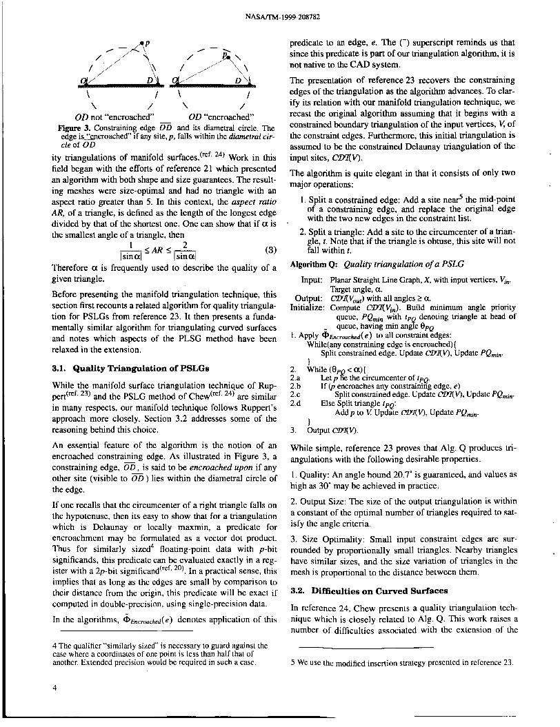
OD not "encroached" OD "encroached" Figure 3. Constraining edge and its diametral circle. The edge is3ncroached" if any site, p . falls within the diametral cir- cle of OD
ity triangulations of manifold surfaces.(='. 24) Work in this field began with the efforts of reference 21 which presented an algorithm with both shape and size guarantees. The result- ing meshes were size-optimal and had no triangle with an aspect ratio greater than 5. In this context, the aspect ratio AR, of a triangle, is defined as the length of the longest edge divided by that of the shortest one. One can show that if 01 is the smallest angle of a triangle, then
2 - 5 A R s - 1 I sin 011 I sin 011 (3)
Therefore 01 is frequently used to describe the quality of a given triangle.
Before presenting the manifold triangulation technique, this section first recounts a related algorithm for quality triangula- tion for PSLGs from reference 23. It then presents a funda- mentally similar algorithm for triangulating curved surfaces and notes which aspects of the PLSG method have been relaxed in the extension.
3.1. Quality Triangulation of PSLGs
While the manifold surface triangulation technique of Rup- pedRf. 23) and the PSLG method of Chew(Ef. 24) are similar in many respects, our manifold technique follows Ruppert's approach more closely. Section 3.2 addresses some of the reasoning behind this choice.
An essential feature of the algorithm is the notion of an encroached constraining edge. As illustrated in Figure 3, a constraining edge, OD, is said to be encroached upon if any other site (visible to 00) lies within the diametral circle of the edge.
If one recalls that the circumcenter of a right triangle falls on the hypotenuse, then its easy to show that for a triangulation which is Delaunay or locally maxmin, a predicate for encroachment may be formulated as a vector dot product. Thus for similarly sized4 floating-point data with p-bit significands, this predicate can be evaluated exactly in a reg- ister with a 2p-bit significand(rcf, ''). In a practical sense, this implies that as long as the cdgcs are small by comparison to their distancc from the origin, this predicate will be exact if computed in doublc-precision, using single-precision data.
In the algorithms, 6 ~ ~ ~ ~ , , ~ ~ h ~ d ( e ) denotes application of this
4 Thc qualifier "similarly sizcd" is ncccssary to guard against thc casc wherc a coordinatcs of one point is lcss than half that of anothcr. Extended prccision would be required in such a case.
predicate to an edge, e. The (-) superscript reminds us that since this predicate is part of our triangulation algorithm, it is not native to the CAD system.
The presentation of reference 23 recovers the constraining edges of the triangulation as the algorithm advances. To clar- ify its relation with our manifold triangulation technique, we recast the original algorithm assuming that it begins with a constrained boundary triangulation of the input vertices, V , of the constraint edges. Furthermore, h s initial triangulation is assumed to be the constrained Delaunay triangulation of the input sites, CDl(V).
The algorithm is quite elegant in that it consists of only two major operations:
1. Split a constrained edge: Add a site ne& the mid-point of a constraining edge, and replace the original edge with the two new edges in the constraint list.
2. Split a triangle: Add a site to the circumcenter of a trian- gle, t. Note that if the triangle is obtuse, this site will not fall within t .
Algorithm Q: Quality triangulation of a PSLG
Input: Planar Straight Line Graph, X, with input vertices, Vi,. Target angle, a.
Output: Cm(V,,,) with all angles 2 a. Initialize: Compute cm(V,,). Build minimum angle priority
queue, PQmin with t p denoting triangle at head of
1. Apply 6 ~ ~ ~ ~ ~ ~ h ~ d ( e ) to all constraint edges: queue, having min ang f e 0 p ~
While(any constraining edge is encroached){
I Split constrained edge. Update WV), Updatc PQ,,,.
Let p ge the circumcenter of tpQ. If (p encroaches any constraining edge, e)
2. While ( 8 p <a){ 2.a 2.b 2.c 2.d Else Split triangle t p ~ :
Split constrained edge. Update Mn(V), Update PQmin.
Add p to V Update WV), Update PQ,,,. 1
3. Output cm(V).
While simple, reference 23 proves that Alg. Q produces tri- angulations with the following desirable properties.
1. Quality: An angle bound 20.7" is guaranteed, and values as high as 30" may be achieved in practice.
2. Output Size: The size of the output triangulation is within a constant of the optimal number of triangles required to sat- isfy the angle criteria.
3. Size Optimality: Small input constraint edges are sur- rounded by proportionally small triangles. Nearby triangles have similar sizes, and the size variation of triangles in the mesh is proportional to the distance between them.
3.2. Difficulties on Curved Surfaces
In reference 24, Chew presents a quality triangulation tech- nique which is closely related to Alg. Q. This work raises a number of difficulties associated with thc extension of the
5 we USC thc modified insertion strategy prcscntcd in rcfcrcnce 23.
4
NASAfl'M-1999-208782
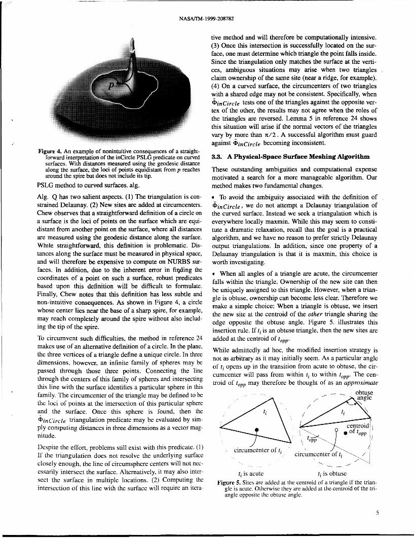
Figure 4. An example of nonintuitive consequences of a straight- forward interpretation of the incircle PSLG predicate on curved surfaces. With distances measured using the geodesic distance along the surface, the loci of points equidistant from p reaches around the spire but does not include its tip.
PSLG method to curved surfaces. alg.
Alg. Q has two salient aspects. (1) The triangulation is con- strained Delaunay. (2) New sites are added at circumcenters. Chew observes that a straightforward definition of a circle on a surface is the loci of points on the surface which are equi- distant from another point on the surface, where all distances are measured using the geodesic distance along the surface. While straightforward, this definition is problematic. Dis- tances along the surface must be measured in physical space, and will therefore be expensive to compute on NURBS sur- faces. In addition, due to the inherent error in fiqding the coordinates of a point on such a surface, robust predicates based upon this definition will be difficult to formulate. Finally, Chew notes that this definition has less subtle and non-intuitive consequences. As shown in Figure 4, a circle whose center lies near the base of a sharp spire, for example, may reach completely around the spire without also includ- ing the tip of the spire.
To circumvent such difficulties, the method in reference 24 makes use of an alternative definition of a circle. In the plane, the three vertices of a triangle define a unique circle. In three dimensions, however, an infinite family of spheres may be passed through those three points. Connecting the line through the centers of this family of spheres and intersecting this line with the surface identifies a particular sphere in this family. The circumcenter of the triangle may be defined to be the loci of points at the intersection of this particular sphere and the surface. Once this sphere is found, then the Gincircle triangulation predicate may be evaluated by sim- ply computing distances in three dimensions as a vector mag- nitude.
Despite the effort, problems still exist with this predicate. (1) If the triangulation does not resolve the underlying surface closely enough, the line of circumsphere centers will not nec- essarily intersect the surface. Alternatively, it may also inter- sect the surface in multiple locations. (2) Computing the intersection of this line with the surface will require an itera-
tive method and will therefore be computationally intensive. (3) Once this intersection is successfully located on the sur- face, one must determine which triangle the point falls inside. Since the triangulation only matches the surface at the verti- ces, ambiguous situations may arise when two triangles ,
claim ownership of the same site (near a ridge, for example). (4) On a curved surface, the circumcenters of two triangles with a shared edge may not be consistent. Specifically, when &incircle tests one of the triangles against the opposite ver- tex of the other, the results may not agree when the roles of the triangles are reversed. Lemma 5 in reference 24 shows this situation will arise if the normal vectors of the triangles vary by more than n/2. A successful algorithm must guard against Gincircle becoming inconsistent.
3.3. A Physical-Space Surface Meshing Algorithm
These outstanding ambiguities and computational expense motivated a search for a more manageable algorithm. Our method makes two fundamental changes.
To avoid the ambiguity associated with the definition of @incircle , we do not attempt a Delaunay triangulation of the curved surface. Instead we seek a triangulation which is everywhere locally maxmin. While this may seem to consti- tute a dramatic relaxation, recall that the goal is a practical algorithm, and we have no reason to prefer strictly Delaunay output triangulations. In addition, since one property of a Delaunay triangulation is that it is maxmin, this choice is worth investigating.
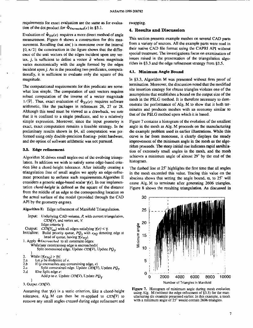
When all angles of a triangle are acute, the circumcenter falls within the triangle. Ownership of the new site can then be uniquely assigned to this triangle. However, when a trian- gle is obtuse, ownership can become less clear. Therefore we make a simple choice: When a triangle is obtuse, we insert the new site at the centroid of the other triangle sharing the edge opposite the obtuse angle. Figure 5. illustrates this insertion rule. If ti is an obtuse triangle, then the new sites are added at the centroid of topp.
While admittedly ad hoc, the modified insertion strategy is not as arbitrary as it may initially seem. As a particular angle of ti opens up in the transition from acute to obtuse, the cir- cumcenter will pass from within ti to within topp. The cen- troid of topp may therefore be thought of as an approximate
-
1 L G l VI 'i circumcenteCof ti-"-.
ti is acute ti is obtuse Figure 5. Sites are added at the centroid of a triangle if the trian-
gle is acute. Otherwise they are added at the centroid of the tn- angle opposite the obtuse angle.
5

N A S m - 1999-208782
circumcenter of ti. Denoting the radius of the circumcircle of ti as R, it can be shown that if one chooses an approximate circumcenter within a distance fR of the true circumcenter, then an angle bound of
(4)
may still be achieved. Reference 24 contends that even using approximate circumcenters, angle bounds of 30" may be achieved in practice.
With these changes, the manifold triangulation algorithm becomes:
Algorithm M:
asasin(-) 1-f 2
Quality Manifold triangulation of a CAD volume.
Input: Underlying CAD volume, P, with initial triangulation Sc, and input vertices, vi,.
Target angle, a. Output: a V o u , ) with all angles 2 a.
Initialize: Compute constrained locally maxmin triangulation Vi,), using cad-edge entities as constraints.
Build minimum angle priority queue, f Qmh with tpQ denoting triangle at head of queue, having min angle OPQ.
1. Apply &Encroached to all constraint edges: While(any constraining edge is encroached)(
Split constrained edge. Update CXNV), Update fQmh. I
2. While (epQ c a){ 2.a If ( t p is not obtuse)
2.b 2.c 2.d Else Split triangle t :
fssign t := r p p with circumcenterp. Else Assign t:= topp with centroid p . If (p encroaches any constraining edge, e)
Split constrained edge. Update CXNV), Update PQmin.
Add p to K Update CXNV), Update f Qmifl.
I 3. output a!qV).
When the algorithm terminates, all angles are greater than a . Thus, it recovers the properties of quality and size-optimality cited after the presentation of Alg. Q in 53.1. The bound on output size, however, depends on the site insertion strategy always inserting new vertices within the circumcircle of 'PQ? (ref. 23) and the modified strategy will not always guaran- tee this, thus the algorithm sacrifices strict proof of this prop- erty.
The new algorithm requires initialization with a transforma- tion of the part's original constrained manifold triangulation Sc to one which is everywhere locally maxmin. If we assume the existence of a triangulation predicate ~ X N which can be enforced for every pair of triangles sharing an edge in thc tri- angulation (similar to the application of Gincircle ), then this initialization may be performed with edge swccps fol- lowed by edge-swapping whcn a violation is encountcrcd. Whilc thc possibility of multiple sweeps makes this a seem- ingly incfficicnt approach, wc rccall that the initial complcx- ity of Sc is only proportional to thc number of cad-cdgcs in the geometric SLructurc. Thus this simplistic approach is not a problem.
Sitc insertion procccds in a manncr comparablc to thc PSLG algorithm. A convcnicnt implemcntalion makcs usc of thc
incremental insertion strategy of reference 25. However, since the triangulation is no longer Delaunay, both forward and reverse propagation is necessary after edge swaps. Sites from edge or triangle splitting must be projected to their actual locations on the underlying surface, and the native constructors are used for this through the CAD API. Reference25 gives a modified point placement strategy for splitting encroached edges. Our implementation of Alg. M adopts this strategy without modification.
3.4. Triangulation Predicates
Algorithm M rests on two new triangulation predicates. The first tests a triangle for an obtuse angle, &ob( t ) and the sec- ond, & x N ( e ) , tests if the edge, e, shared by any two triangles maximizes the minimum angle in both triangles. This is accomplished by comparison with a swapped edge, e ', which connects the opposite vertices of the two triangles. Our approach hinges on the hope of evaluating these predicates robustly in physical space.
Both of these predicates can be formulated with direct mea- surement of the angles in a mesh. Since a triangle has three points, it uniquely defines a plane in three dimensions. Angle measurement in a plane is unambiguous - despite the fact that the triangles form a discrete manifold which is of lower dimension than the surrounding space. Numerically, we recall that since all vertex locations returned by the CAD engine are considered exact, the error bound on the input is identically zero.
G o b ( [ ) IS applied by a logical or accumulation of $L, - 1, ,, , + 1 , where j is a cyclic index running over the verti- ces of r, j E { 1,2,3} . This angle predicate is formed by com- parison of the square of the edge opposite j to that of a hypothetical edge formed by assuming that the edges of f incident on j form a right angle in the plane oft.
where
Notice that eq. (6) requires only subtraction and multiplica- tion of data which is known exactly. Thus the computational
2 Figure 6. Construction for 121 , thc squarc of thc magniiudc of thc difference of unit vectors incidcni on vertex j .
6
~~ ~
NASAfTM-2999-208782
requirements for exact evalyation are the same as for evalua- tion of the dot product for (PEncroackd(e) in 53.1.
Evaluation of &.,( e ) requires a more direct method of angle measurement. Figure 6 shows a construction for this mea- surement. Recalling that sin( ) is monotone over the interval [O, z/2] the construction in the figure shows that the differ- ence of the unit vectors of the edges incident upon any ver- tex, j, is sufficient to define a vector 2 whose magnitude varies monotonically with the angle formed by the edges incident upon j. As in the preceding two predicates, computa- tionally, it is sufficient to evaluate only the square of this magnitude.
The computational requirements for this predicate are some- what less simple. The computation of unit vectors requires robust computation of the inverse of a vector magnitude l /IVl. n u s , exact evaluation of 6 x N ( e ) requires software arithmetic, like the packages in references 26, 27 or 28. Although this need must be viewed as a drawback, we note that it is confined to a single predicate, and to a relatively simple expression. Moreover, since the input geometry is exact, exact computation remains a feasible strategy. In the preliminary results shown in 54, all computation was per- formed using only double-precision floating- point hardware, and the option of software arithmetic was not pursued.
3.5. Edge refinement
Algorithm M drives small angles out of the evolving triangu- lation. In addition we wish to satisfy some edge-based crite- rion like a chord-height tolerance. After initially creating a triangulation free of small angles we apply an edge-refine- ment procedure to enforce such requirementsAgorithm E considers a generic edge-based scalar He). In our implemen- tation chord-height is defined as the square of the distance from the middle of an edge to the corresponding location on the actual surface of the model (provided through the CAD API by the geometry engine).
Algorithm E: Edge refinement of Manifold Triangulation.
Input: Underlying CAD volume, P, with current triangulation,
Edge criteria y. Output: CXT&,J with all edges satisfying y(e) C 'y.
Initialize: Build priority queue, PQr with epQ dcnoting edge at
1. Apply &Encroached to all constraint edges:
CK!A@), and vertex set, V
head of queue, having r(t?pQ).
While(any constraining edge is encroached){
1 Split constrained edge. Update CXMV), Update PQr
2. While ('l(epQ) > 'I){ 2.a 2.b 2.c 2.d Else Split edge e:
Let p be midpoint of e. If (p encroaches any constraining edge, e)
Split constrained edge. Update WV), Update PQr
Addp to e. Update CXNV), Update PQr 1
3. output CXMV).
Assuming that y(e) is a static criterion, like a chord-height tolerance, Alg. M can then be re-applied to CXNV) to remove any small angles created during edge refinement and
swapping.
4. Results and Discussion
This section presents example meshes on several CAD parts from a variety of sources. All the example parts were read in their native CAD file format using the CAPRI API without special treatment. The investigations focus on examination of issues raised in the presentation of the triangulation algo- rithm in 53.3 and the edge refinement strategy from 53.5.
4.1. Minimum Angle Bound
In 53.3, Algorithm M was presented without firm proof of termination. Moreover, the discussion noted that the modified site insertion strategy for obtuse triangles violates one of the assumptions that establishes a bound on the output size of the mesh in the PSLG method. It is therefore necessary to dem- onstrate the performance of Alg. M to show that it both ter- minates and produces meshes with an economy similar to that of the PSLG method upon which it is based.
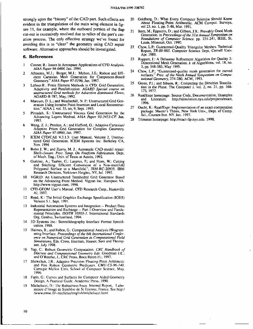
Figure 7 contains a histogram of the evolution of the smallest angle in the mesh as Alg. M proceeds on the manufacturing die example problem used in earlier illustrations. While this curve is far from monotone, it clearly displays the steady improvement of the minimum angle in the mesh as the algo- rithm proceeds. The steep initial rise indicates rapid annihila- tion of extremely small angles in the mesh, and the mesh achieves a minimum angle of almost 29" by the end of the his togram.
The dashed line at 25' highlights the first time that all angles in the mesh exceeded this value. Tracing this value on the abscissa shows that setting the angle bound, a, to 25' will cause Alg. M to terminate after generating 2606 triangles. Figure 8 shows the resulting triangulation. As discussed in
0 ~ ' ' " ' ' - ' " ~ ' L - ' ' " ' " " ' ' L ' " ' ' I 0 2000 4000 6000 8000 10000
Number of Triangles in Manifold
Figure 7. Histogram of minimum angle during mesh evolution using Alg. M (without the edge refinement of $3.5) for the man- ufacturing die example presented earlier. In this example, a mesh with a minimum angle of 25" would contain 2606 triangles.
7

NASAflW-1999-208782
Figure 8. Quality manifold triangulation for manufacturing die example generated with Alg. M. in $3.3. Mesh improvement terminated after generating 2606 triangles when the mini- mum angle in the triangulation reached 25". Chord-height
$3.1 and $3.3, the presence of an angle bound ensures that small features are surrounded by proportionally small trian- gles (see the inset frames in figure 8), and that the mesh length-scale varies smoothly over the part. The smallest angle in the mesh is 25.02', which corresponds to a maxi- mum aspect ratio of between 2.36 and 4.7 (by eq. (3)).
While the histogram in Figure 7 shows a steady increase in the minimum angle, there is an irregular array of downward spikes in the profile. In the presentation of the PSLG algo- rithm, reference 23 included a similar histogram and noted the same characteristic. Consider the two triangles tl and t2 shown at the left in Figure 9, Assume that €4 is the smallest angle in the mesh lying in triangle t l . Furthermore, assume that tl's face neighbor, t2, has a small angle 0, opposite the shared edge which is only slightly larger than €4. Site p will get added at ti's circumcenter, improving 01 to 20,. After application of the maxmin predicate ~ X N on the shared edge, the swapped configuration at the right of Fig.9 may occur. This configuration includes two new triangles with minimum angles 03 and 04 either of which may now be the smallest angle in the mesh and may actually be smaller than the origi- nal angle 0 1.
With this behavior understood, Figures 10 and 11 present angle histograms and example meshcs for a more compli-
Before Insertion of site p at circumcenter of 11 AJer site insertion and swapping
Figure 9. Mcchanism rcsponsiblc for downward spikcs in histo- gram of minimum anglc as Alg. M procecds. I f 8, is initidly thc smallest anglc in thc mesh, anglcs 8 and 04 may be smaller after inscrtion of p and cnforccmcnt of d, by cdgc-swapping.
cated assembly of parts. Alg. M was run on CAD parts for the main element of a transport wing, and a flap element for the same wing. The main element consisted of 224 rational B-spline curves and 36 trimmed NURBS surfaces. The flap contained 31 rational B-spline curves and 10 trimmed NURBS surfaces.
The crosshairs on the curves in figure10 show that with a 25" angle bound, Alg. M will produce 20846 triangles on the main element and 15334 triangles on the flap. Figure 11 dis- plays these triangulations.
The histograms in Figure 10 bear close resemblance to the one presented for the simple die example shown in figure 7. All of these profiles are characterized by a sharp initial angle improvement and then a rolling-off as the minimum angle climbs above about 20'. All three profiles exceed 27", but
CAD system: ProE 1 0
0 20000 40000 Number of Triangles in Manifold - - - - , , , . , , , , , , - - - . ~ T
I t Flap !
30, ' ' ' ' ' ' F
I I I
5 1 I I
I i 0 -J
0 10000 20000 30000
I CADsystem ProE
Number of Triangles in Manifold
Figure 10. Angle histograms for Alg. M on the main clcmcnt of a transport wing(uppcr), and on thc main flap (lower). An anglc bound of 25" would produce triangulations with 20846 and 15334 triangles on the main elcmcnt and flap rcspcctivcly.
8

NASm-1999-208782
Figure 11. Bounded angle triangulations of main element of a transport aircraft wing and flap generated by Alg. M in 83.3. Minimum angle 25", 20846 triangles on wing, 15334 triangles on flap.
reaching 30" seems unlikely.
The abscissa values in figure 10 indicate relatively large tri- angulations as compared with the die example. The size-opti- mality property cited in $3.1 and $3.3 implies that triangle size must vary smoothly between different sized constraints. In both of these examples the smallest constraint in the CAPRI triangulation was a factor of io4 smaller than the largest constraining edge. In addition, practical experience with the algorithm indicates that larger initial triangulations, S,, (eq. (2)) have a proportionally slower initial rise in their angle profiles. This seems reasonable since if the CAPRI tri- angulation is complex there may initially be many bad angles which need improvement. Often CAD parts are unnecessarily complex for reasons dating to the specific events in their cre- ation. Our experience with CAD repair software indicates that CAPRI generally produces less complex (sometimes by an order of magnitude) initial triangulations if the parts have been processed by CAD repair tools. Since tolerance to poor CAD parts is one type of robustness that we seek in this research, neither part shown in Fig. 1 1 underwent such repair prior to creation of these triangulations.
With the minimum mesh angle restricted to 25", triangles are again restricted to aspect ratios less than 4.7. Such an isotro-
ture in only one dimension. Therefore, if one intends to produce meshes for viscous computation, a substantially smaller angle bound may be appropriate.
4.2. Chord-Height Refinement
Enforcement of the angle bound does not guarantee that the edges are refined when they are sufficiently far from the underlying surface. Alg. E in $3.5 presented an edge refine- ment strategy for automatically breaking edges whose mid- points are far from the geometry. Figure 12 shows an interior comer of the die examde after the imDosition of a chord-
I pic mesh is very inefficient at meshing features with curva-
Figure 12. Interior comer of manufacturing die example trian- gulation after imposition of a chord-height tolerance of 1 . ~ 1 0 ~ normalized by the maximum outer dimension of the part. Edge refinement was performed using Alg. E. in 53.5
outer dimension of the part. Away from the curved interior comers, the triangulation remains unchanged since the faces
5. Conclusions and Future Work
, of the die are planar.
5.1. Conclusions
This paper examined the direct use of CAD geometry in sur- face meshing. It argued in favor of accessing CAD parts and assemblies in their native format, without translation and for the use of CAD-native predicates and constructors in mesh generation. The discussion also contended that since physi- cal-space mesh generation techniques permit exact numerical computation, they can be more robust than their mapped- space counterparts.
The feasibility of this approach was demonstrated by applica- tion to a novel, physical-space, curved surface meshing algo- rithm to several CAD parts. Model data was accessed in its native format using the CAPRI API. This triangulation algo- rithm maintained a locally maxmin triangulation and used an approximate circumcenter site insertion strategy. All triangu- lation predicates were formulated for evaluation in physical- space, and examples demonstrated that the method produced a bounded aspect ratio manifold triangulation. The computa- tional requirements for exact evaluation of all triangulation predicates were discussed. The algorithm was demonstrated on CAD parts of varying complexity and reliably produced triangulations with minimum angles in excess of 27".
5.2. Future Research
Although Alg. M. produces meshes with generally smooth length-scale variation, there is occasionally a discernible irregularity in the triangulations. This behavior becomes more pronounced when higher angle bounds are specified. Similar behavior has been noted in the PSLG algorithm 23, although in two dimensions, the behavior seems less pro- nounced. One possible source for this is the abrupt change in insertion location from circumcenter to centroid (of topp) if an obtuse triangle is encountered. Alternative strategies should be investigated since this behavior can degrade the efficiency of the triangulations.
height tolerance of times L, where L is the maximum The initial triangulation returned by CAPRI depends
9
NASAITM- 1999-208782
strongly upon the “history” of the CAD part. Such effects are evident in the triangulation of the main wing element in fig- ure 11, for example, where the outboard portion of the flap cut-out is excessively resolved due to relics of the part’s cre- ation process. The only effective strategy we’ve found for avoiding this is to “clean” the geometry using CAD repair software. Alternative approaches should be investigated.
6. References
1
2
3
4
5
6
7
8
9
10
11
12
13
14
15
16
17
18
19
Cosner, R.: Issues in Aerospace Applications of CFD Analysis. AIAA Paper 94-0464, Jan. 1994.
Aftosmis, M.J.; Berger, M.J.; Melton, J.E.: Robust and Effi- cient Cartesian Mesh Generation for Component-Based Geometry.” AIAA Paper 97-0196, Jan. 1997.
L6hner.R.: Finite Element Methods in CFD: Grid Generation, Adaptivity and Parallelization. AGARD Special course on unstructured Grid methods for Advection dominated Flows, AGARD-R-787, May, 1992.
Marcum, D. L.; and Weatherhill, N. P.: Unstructured Grid Gen- eration Using Iterative Point Insertion and Local Reconstruc- tion.” A I M J. vol. 33, no, 9, Sept. 1995.
Pirzadeh, S.: Unstructured Viscous Grid Generation by the Advancing Layers Method. AIM Paper 93-3453-CfI Jun. 1993.
Wang, Z. J.; Przekas, A,; and Hufford, G.: Adaptive Cartesian/ Adaptive Prism Grid Generation for Complex Geometry. AIAA Paper 97-0860, Jan. 1997.
ICEM CFD/CAE V.3.1.3: User Manual, Volume 2, Unstruc- tured Grid Generation. ICEM Systems Inc. Berkeley CA, Nov. 1994.
Bohn J. W.; and Zozny, M. J.: Automatic CAD-model repair: Shell-closure. Proc. Symp. On Freeform Fabrication. Dept. of Mech. Eng.; Univ. of Texas at Austin, 1992.
Gutziec, A,; Taubin, G.; Lazarus, F.; and Horn, W.: Cutting and Stitching: Efficient Conversion of a Non-manifold Polygonal Surface to a Manifold.”, IBM-RC-20935. IBM Research Division, Yorktown Heights, NY, Jul. 1997.
VGRID: An Unstructured Tetrahedral Grid Generator Based on the Advancing Front Method. Vigyan Inc. Hampton VA. http://www.vigyan.com, 1998.
CFD-GEOM User’s Manual. CFD Research Corp., Huntsville AI, 1997.
Reed, K.: The Initial Graphics Exchange Specification (ICES) Version 5.1. Sept. 1991.
Industrial Automation Systems and Integration -- Product Data Representation and Exchange -- Part 1 :Overview and Funda- mental Principles. ISO/TR 10303-1. International Standards Org. Gentve, Switzerland, 1994.
3D Systems Inc.: Stereolithography Interface Format Spccifi- cation. 1988.
Haimes, R.; and Follen, G.: Computational Analysis PRogram- ming Interface. Proceedings of the 6th International Confer- ence on Numerical Grid Generation in Computational Field Simulations, Eds. Cross, Eiseman, Hauscr, Soni and Thomp- son, July 1998.
Yap, C.: Robust Geometric Computation. CRC Handbook of Discrete and Computational Geometry Eds. Goodman J.E.; and O’Rourkc, J., CRC Press, Boca Raton Fl.; 1997.
Shcwchuk, J.R.: Adaptive Precision Floating-point Arithmetic and Fast Robust Geometric Prcdicatcs. CMU-CS-96-140. Camcgic Mcllon Univ. School of Computcr Scicncc, May, 1996.
Farin, G.: Curves and Surfaccs for Computcr Aidcd Gcomctry Design, A Practical Guidc. Academic Prcss, 1990.
Michclucci, D.: Thc Robustncss Issuc. lntcrnal Rcport, Labo- ratoirc d’lmagc dc Synthksc de St Eticnnc, France. Scc http:/ /www.emsc. fr/-michcluc/cnglish/michclucci.html
20
21
22
23
24
25
26
27
28
Goldberg, D.: What Every Computer Scientist Should Know About Floating-point Arithmetic. ACM Comput. SurVeyS, vol23, no. 1, pp. 5-48, Mar. 1991.
Bern, M.; Eppstein, D.; and Gilbert, J.R.: Provably Good Mesh Generation. in Proceedings of the 31st Annual Symposium on Foundations of Computer Science. pp. 231-241, E E E , St. Louis, Missouri, Oct. 1990.
Chew, L.P.: Guaranteed-Quality Triangular Meshes. Twhnical Report, TR-89-983. Computer Science Dept, Cornell UiV. Apr. 1989.
Ruppert, J.: A Delaunay Refinement Algorithm for Quality 2- Dimensional Mesh Generation. J. of Algorithms, vol. 18, no. 3, pp. 548-585, May 1995.
Chew, L.P.; “Guaranteed-quality mesh generation for curved surfaces.” Proc. of the Ninth Annual Symposiwn on Compu- tational Geometry, 274-280. ACM, 1993.
Green, P.J.; and Sibson, R.: Computing the Dirichlet Tessella- tion in the Plane. The Computer J. vol. 2, no. 21, pp. 168- 173, 1977.
Real/Expr homepage: Source Code, Documentation, Examples and Literature. http://simulation.nyu.edu/projects/exact, 1996.
Ouchi, K.: ReaVExpr: Implementation of an exact computation package. Master’s Thesis, New York Univ., Dept. of Comp. Sci., Courant Inst. NY. Jan. 1997.
Trimaran homepage: http://react-ilp.nyu.edu. 1998.
I O
RE PORT DOC ii Ne E NTATlO N PAGE
14. SUBJECT TERMS
Triangulation algorithm, CAD, Curved surface
17. SECURITY CLASSIFICATION 18. SECURITY CLASSIFICATION 19. SECURITY CLASSIFICATION OF REPORT OF THIS PAGE OF ABSTRACT
Unclassified Unclassified
Form Approved 0.W .NO. 0704-0788
15. NUMBER OF PAGES
15
A03 16. PRICE CODE
20. LIMITATION OF ABSTRAC
Public reporting burden for this collection of information is estimated to average 1 hour per response. including the time tor reviewing instructions. searching extsting data sources, gathenng and maintaining the data needed, and completing and reviewing the collection of information Send comments regarding this burden estimate or any other aspect of this Collection of Information. including suggestions for reducing this burden, to Washington Headquarters Services. Directorate for information Operations and Reports, 1215 Jefferson Davis Highway, Suite 1204, Arlington, VA 22202-4302. and to the Office of Management and Budget. Paperwork Reduction Prqect (0704-0188), Washinpton, DC 20503
1. AGENCY USE ONLY (Leave blank) 3. REPORT TYPE AND DATES COVERED
Technical Memorandum 4. TITLE AND SUBTITLE
On the Use of CAD-Native Predicates and Geometry in Surface Meshing
6. AUTHOR(S)
M. J. Aftosmis
7. PERFORMING ORGANIZATION NAME(S) AND ADDRESS(ES)
Ames Research Center Moffett Field, CA 94035-1000
9. SPONSORlNGlMONlTORlNG AGENCY NAME(S) AND ADDRESS(ES)
National Aeronautics and Space Administration Washington, DC 20546-0001
5. FUNDING NUMBERS
522-31 - 12
8 . PERFORMING ORGANlZATldN REPORT NUMBER
A-99V0022
IO. SPONSORlNGlMONlTORlNG AGENCY REPORT NUMBER
NASA/TM-1999-208782
11. SUPPLEMENTARY NOTES
Point of Contact: M. J. Aftosmis, Ames Research Center, MS T27B-2, Moffett Field. CA 94035-1000 (650) 604-4499
12a. DlSTRlBUTlONlAVAlLABlLlTY STATEMENT
Unclassified - Unlimited Subject Category 61 Distribution: Standard Availability: NASA CAS1 (301) 621-0390
13. ABSTRACT (Maximum 200 words)
12b. DISTRIBUTION CODE
Several paradigms for accessing computer-aided design (CAD) geometry during surface meshing for computational fluid dynamics are discussed. File translation, inconsistent geometry engines, and nonnative point construction are all identified as sources of nonrobustness. The paper argues in favor of accessing CAD parts and assemblies in their native format, without translation, and for the use of CAD-native predi- cates and constructors in surface mesh generation. The discussion also emphasizes the importance of examining the computational requirements for exact evaluation of triangulation predicates during surface meshing.