Embed Size (px)
Citation preview
\ t and f a t a l i n j u r i e s t o a l l t e n persons aboard, the Air Sa fe ty Board of t h e
s Authority on t he same day, d i r e o t e d t h a t f u l l and complete inves t iga t ion ~ .
e . in s t iga t ed immediately pursuant t o t h e provis ions of Seot ion 702 (a ) (2) Of
tios Aot of 1938 (52 S t a t . 973, 1013) . and t h a t t h e faots, condi t ions , and
a t i n g t o t h e aooident and t h e probable oause thereof be determine$. It was
hat the inves t iga t ion include suoh f i e l d i n v e s t i g a t i o n and research and suoh
e hear ings as might be considered neoessary.
os8 of oarry,ing out t h e above order , t h e Air Sa fe ty Board designated Frank
e f of t he
.-
Inves t iga t ion Seot ion of t he Air Sa fe ty Board, as Inves t iga to r i n
, Chief of t h e Examiners Seot ion of t h e Air S a f e t y Board, as i e g a l
@fnves t iga to r i n oharge dur ing t h e f i e l d inves t iga t ion and as Examiner empower- ~
~c~ . ..~ ,~
onduot suoh pub l i c o r p r i v a t e hear ing or hear ings i n oonnection w i t h the
he Board might d i r e o t . It was f u r t h e r ordered t h a t Mr. Caldwell and Mr.
and advised by P h i l C . Salzman, Air Sa fe ty Inves t iga to r . Air Sa fe ty Board,
Pn, Aeronautioal Engineer, Air Sa fe ty Board, and pursuant t o the' p rovis ions
onautios Aot of 1938, by t h e fol lowing teohnioa l personnel :
- 2 -
Major Carl F. Green ( expe r t on a i r o r a f t s t r u c t u r e s ) , Air Corps, United S t a t e s Army
L t . F. R . Dent ( expe r t on f l u t t e r and v i b r a t i o n ) , A i r Corps. United States Army
Alfred S . Niles (exper t on a i r o r a f t s t r u o t u r e ) , Leland-Stanford Univers i ty Palo Alto, C a l i f o r n i a
R. D . Bedinger, Regional Supervisor, C i v i l Aeronautios Authority
J . N . Boudwin, Senior Engineering Inspec to r . C i v i l Aeronautios Authority
G . RI. Haldeman, Engineering Inspeotor , C i v i l Aeronautios Author i ty
H. C . S ine , Assooiate A i r c r a f t Inspeotor . C iv i l Aeronautios Authority
A . D . Niemeyer, Air C a r r i e r In spec to r , C i v i l Aeronautios Author i ty
0 . A . Rosto, Air C a r r i e r Inspeotor (Maintenanoe), C i v i l Aeronautios Authority
F. Hammerberg, Assooiate Aeronautic1 Engineer, C i v i l Aeronautios Authority
Id . P. Crews, Aeronautioal Engineer. C i v i l Aeronautios Author i ty .
The a i r Sa fe ty Board f u r t h e r ordered t h a t a l l phases of the inves t iga t ion . research
ndrhearing or hear ings be o a r r i e d out under the d i r e o t superv is ion of Thomas 0 . Hardin, Vice
man, and C. 8. Allen, Member, Air Sa fe ty Board.
Inves t iga t ion of t h e aooident was begun on t h e 19th day of Maroh. 1939, by t h e above-
d personnel and the pub l i c hearing i n oonneotion therewi th was ordered and he ld i n the
of S e a t t l e , S t a t e of Washington, on t h e 30th and 31st days of Maroh, 1939, and the '3d .
I n add i t ion t o the personnel a l ready named, the t h , 6 th and 7 t h days of Apr i l , 1939.
tanoe of t h e following agencies and organiza t ions was s o l i o i t e d and obtained:
- 3 -
0- Civ i l Aeronautios Authori ty
4 Air Corps, United S t a t e s Army
Bureau of Aeronautics, United S t a t e s Navy
Bureau.of Standards, United S t a t e s Department of Commerce
I
Federal Bureau of Inves t iga t ion , Department of J u s t i c e
National Advisory Committee f o r Aeronaut ics
Having considered t h e evidence adduced during the inves t iga t ion , the following f a c t s ,
oondi t ions, and circumstances r e l a t i n g t o the accident and conclusion as t o t h e probable
oause thereof are hereby reported, and recommendations, which, i n t h e opinion of t he Air
Sa fe ty Board, w i l l tend t o prevent s i m i l a r acc idents i n the fu tu re . a r e hereby made. t o the
C iv i l Aeronautics Authority:
FACTS, CONDITIONSAND CIRCUMSTANCES
Airoraft NX 19901, manufactured by t h e Boeing A i r c r a f t Company of S e a t t l e , Washington,
a corporat ion organized and e x i s t i n g under and by v i r t u e of the laws of the S t a t e of Washing-
ton. was a four-engine all-metal low-wing land monoplane designed f o r commercial operat ion
and h0Wn as Boeing Model S-307. It had a wing span of 10'7' 3" and an ove ra l l length of 74 '
4". Provis ion had been made f o r op t iona l i n s t a l l a t i o n s r equ i r ing crews of 3 o r 6, during
Commercial cpera t ion , and For a maximum of 33 passengers . The a i r c r a f t . whioh weighed 28,900
pounds empty and bore the manufaoturer 's s e r i a l number 1994, was . issued a temporary experi-
mental C e r t i f i c a t e by t h e C iv i l Aeronautics Authori ty on December 30, 1938, autho:izing
f l i g h t w i t h a s tandard gross weight of 41,000 pounds. T h i s au tho r i za t ion was amended i n
January, 1939, t o permit a s tandard gross weight of 41,000 pounds and a p rov i s iona l gross
weight Of 45,000. Both au tho i i za t ions p roh ib i t ed t!78 c a u i a g e of persons o ther than bona
fide members of t he orew.
NERAL DESCRIPTION OF AIRCRAFT
T h i s airoraft was powered with four Wright Cyclone GR-18200-102 engines manufactured
- 4 -
by the Wright Aeronautioal Corporation.
ings as follows:
Eaoh of these four engines had aporoved power rat-
(a) Maximum, exoept take-off, a t 6000 f t . p ressure a l t i t u d e - 900 horsepower with 35
inohes of meroury manifold pressure and 2200 r.p.m.
(b) Maxium, exoept take-off, a t sea l e v e l p re s su re a l t i t u d e - 900 horsepower with
36.7 inohes of meroury manifold p re s su re and 2200 r.p.m.
( 0 ) Take-off (one minute) 1100 horsepower with 43 inohes of meroury manifold pressure
and 2200 or 2350 r.p.m.
The p rope l lo r s i n s t a l l e d on t h e a i rcraf t were of t he hydromatio quick-feathering type
with Oonstant speed cont ro l . and were manufaotured by Hamilton Standard P rope l l e r s , Divis ion
of United Airoraf t Corporation, East Har t ford , Conneotiout. Three pf t he p r o p e l l e r hubs were
Model No. 233512-31 and the four th hub, which was i n s t a l l e d on No. 2 engine, was Model NO.
23E50-85. A l l of t h e p rope l l e r b lades ae re Hamilton Standard Model No. 6153A-18. A l l hubs
and blades i n s t a l l e d on t he a i r o r a f t had approved power and speed r a t i n g s which were satis-
faoory for the approved power and speed r a t i n g s of t he engines.
Provis ion had been made i n t h e airoraft f o r a to ta l f u e l oapac i ty O f 1700 ga l lons , t o
be oa r r i ed i n s i x tanks . A main tank a i t h a t o t a l oapaoi ty of 425 ga l lons , and two aux i l i -
a ry tanks. eaoh with a oapaoi ty of 2l2+ ga l lons , were looa ted i n the inboard panel of eaoh
wing. A twenty-five ga l lon o i l tank was i n s t a l l e d i n eaoh engine naoel le , g iv ing a t o t a l
o i l oapaoi ty of 100 ga l lons .
Aerodynamic Desim and Perform-
This a i r o r a f t was of exoept ional ly olean aerodynamic design, a l l wing and t a i l sur- - aoes being f u l l oan t i l eve r i n t e r n a l l y braoed and any long i tud ina l seo t ion through the body
8 symmetrical.
The a i r f o i l s eo t ions Of t h e wing Were the NAbA 0018 symmetrioal section a t the roo t ,
The wing was tapered i n plan d i n t o the NACA 0010 symmetrical s eo t ion a t the t i p .
- 5 -
form, the roo t ohord being approximately two and one-half times t h e t i p ohord.
4;O d ihedra l and was s e t a t 3;.O inoidence w i t h respeot t o the body c e n t e r l i n e .
The wing had
Symmetrical a i r f o i l s e c t i o n s were a l s o used f o r the empennage su r faces , which cons i s t ed
of a s i n g l e f i n and rudder and r i g h t and l e f t ho r i zon ta l s t a b i l i z e r s and e l e v a t o r s .
Test f l i g h t s of t h e a i r c r a f t i n d i c a t e d tha t i t would have a maximum speed i n l e v e l
f l i g h t a t sea l e v e l o f aoout 230 m.p.h., and a maximum l e v e l f l i g h t speed of approximately
250 m.p.h. a t 9000 f e e t dens i ty a l t i t ude . The maximum L over D appeared t o he about 15.
STRUCTURE
- Desian Load+
The design of t h i s a i r o r a f t for a c c e l e r a t e d f l i g h t was based upon an ul t imate design
load f a c t o r of 4.29 w i t h 45,000 pounds p rov i s iona l g ross weight and 4.56 w i t h a s t anda rd
gross weight of 41.000 pounds. The l i m i t loads for the wings, upon whioh the ultimate de-
s i g n loads s e r e based, were such as t o enable t h e aircraft t o withstand 30 f t / s e c . up or
down g u s t s at s e a l e v e l high speed i n l e v e l f l i g h t of 240 m.p.h. , and a 15 f t / s eo . up or
down g u s t s a t a design g l i d i n g speed of 303 m.p.h.
WAG
The wing was of semi-monoooque oonstruot ion and der ived its primary s t r e n g t h from t h e
box formed by two wing s p a r s and t h e smooth and oorrugated aluminum a l l o y s h e e t of t h e t op
and bottom su r faoes between the spars. The p o r t i o n s of t he wing r i b s between the spars
served t o maintain t h e a i r f o i l shape for t h i s part of t h e wing and t o provide the proper
r e s t r a i n t f o r t h e smooth and corrugated wing covering between t h e spars a t eaoh r i b loca t ion .
The wing s p a r s were o f t h e t ru s sed type. The ohords were aluminum a l l o y square tubing,
and t h e web members were aluminum a l l o y b a r r e l and rectangular s e c t i o n tubing. The spar
web members were jo ined t o t h e spar ohords by means o f aluminum a l l o y gusse t p l a t e s whioh
were r i v e t e d and b o l t e d t o the web members and t h e sides of the spar ohords. The oorrugated
s h e e t o f t he t o p and bottom wing s u r f a c e s between t h e spars was o f aluminum a l l o y , and the
- 8 -
smooth sk in covering, which was r i v e t e d t o the corrugated s h e e t a t each cor ruga t ion p i t c h ,
was Alclad aluminum a l l o y . The attachment of the smooth and corrugated covering between
the s p a r s was made through aluminum a l l o y spa r cap p l a t e s r ive t ed t o the tops of t h e upper
Chord members and t h e bottoms of t h e lower chord members of the s p a r s and t o t he covering
by means of aluminum a l l o y r i v e t s . With the except ion of t he spec ia l wing r i b s i n the vi-
o i n i t y of t he wing f u e l tanks, t he wing r i b s were a l l of the t ru s sed type. Their chords
were h a t s eo t ions formed from aluminum a l l o y shee t and the web members, which were a t tached
t o the r ib chords by means of aluminum a l l o y gusse t p l a t e s r i v e t e d t o the chords and web
members, were made from aluminum a l l o y round, square and rec tangular tubing
The leading edge of the wing cons is ted of Alclad aluminum a l l o y shee t r e in fo rced with
corrugated shee t , whioh was a t tached to the nose r i b s by means of aluminum a l l o y r i v e t s .
The attachment of t h e f l a t shee t t o t h e cor ruga t ions was made by means of f lu sh type aluminum
a l l o y r i v e t s . The por t ion of the wing a f t of the rear spar was metal covered. The wings
on e i t h e r s i d e of the body were made i n th ree sec t ions , cons i s t ing of a s h o r t t i p s ec t ion , an
outboard panel, and an inboard panel incorpora t ing the two engine nace l l e s on each s i d e .
The Wing t i p sections and t h e outboard panels were jo ined by means of aluminum a l l o y terminal
f i t t i n g s bol ted t o the spa r chords of t h e outboard panel and by hea t t r e a t e d s t e e l f i t t i n g s
bo l t ed t o the wing t i p , t he te rmina ls being jo ined by means of hea t t r e a t e d s t e e l b o l t s . The
oont inui ty of the w i n g t i p and outboard panel Covering was maintained a t t h i s j o i n t from the
Fear t o the leading edge on both top and bottom su r faces .
The attachment of the outboard wing panels t o the inboard wing panels was made by means
luminum a l l o y terminal f i t t i n g s machined from forged blocks and bol ted t o t h e s p a r c h o r d s .
APE. 2330 s t e e l t ape r p ins were incorporated a t t he hinge. The oorrugat ions and smooth
etween the s p a r s a t t h i s connection were made continuous by means of a s p e c i a l l y de-
j o in t , which y a b l e d the outboard and inboard su r faces t o be connected w i t h s p e c i a l
and b o l t s . Though the con t inu i ty of the s p a r web members was also m a i n t a i n e d a t t h i s
.
po in t , no attempt was made t o preserve the oont inui ty of t h e lead ing edge of t he wing a t
t h i s oonneotion, o t h e r than t o cover up t h e gap. The inboard wing panel was oonneoted t o t h e
body by means of s p e o i a l hea t t r e a t e d S.A.E. 4345 s t e e l t e rmina ls . These te rmina ls were
bol ted t o the spa r ohords and t h e mating members of t he suppor t ing bulkheads i n the body.
while hea t t r e a t e d s t e e l t a p e r p i n s were employed a t t h e hinge. The oon t inu i ty of t h e s p a r
web members was o a r r i e d through i n t o t h e main wing attachment bulkheads i n t h e body.
The bending moments i n t h e beam d i r e o t i o n were r e s i s t e d by the spa rohordsand thesmooth
and oorrugated s k i n between t h e s p a r s . The beam shea r s were c a r r i e d by the t ru s sed spars .
The bending moments, due t o ohord loads , were c a r r i e d by t h e f r o n t and r ea r spa r ohords, and
the shea r s , due t o ohord loads. were supported j o i n t l y by t h e wing oovering between the spa r
ohords and by t h e spa r ohords. The t o r s i o n on the wing was r e s i s t e d by the box formed by the
two s p a r s and the top and bottom covering between t h e spa r s . The wing was s o designed t h a t
no permanent s e t o r f a i l u r e of t h e ma te r i a l between t h e s p a r s was t o be expeoted before per-
manent set or f a i l u r e r e s u l t e d t o t h e spa r ohords. With t h e exoeption of a few minorvaria-
t i o n s , due mainly t o d i f f e rences i n equipment i n s t a l l a t i o n s , t h i s wing was i d e n t i c a l t o the
wing used on t h e Boeing Model 8-178 a i r o r a f t , whioh was ilesigned f o r 45,000 pounds gross
weight and an u l t ima te des ign load f a c t o r of 4.5 .
Though the wing used on a i r c r a f t NX 19901 was n e i t h e r proof t e s t e d nor s t r e n g t h t e s t e d ,
t he s t r e s s ana lys i s methods were s u b s t a n t i a t e d by a s t r e n g t h t e s t of t he o u t e r wing panel of
8 Boeing Model X b 1 5 a i r c r a f t of t h e same genera l type of des ign . In add i t ion , s t a t i o t e s t s
f wings on o the r of t he oommeroial and m i l i t a r y a i r o r a f t p rev ious ly oonstruoted by t h e
e ing Ai ro ra f t Company had been analyzed i n d e t a i l f o r t he purpose of r e f i n i n g the s t r e s s
n a l y s i s methods employed fo r t h i s wing. The allowable loads employed f o r t he numerous
ruotura l members were subs t an t i a t ed by means of numerous supplementary s t a t i o t e s t s where
d neoessary by the Boeing A i r c r a f t Company dur ing the course of t h e a i r o r a f t ' s o o n s t r u o -
- 8 -
E&
The fuselage of t h i s a i r c r a f t , which was of t h e all-metal, semi-monocoque type oonstruo-
t i on , was shaped i n such a manner t h a t every t r ansve r se s e c t i o n from the extreme nose t o the
t i p Of t he t a i l was o i r c u l a r . The s h e l l of t h i s body cons i s t ed of aluminum a l l o y sheet sup-
por ted by a system of t r ansve r se r ings o f "C" sec t ion and by o lose ly spaced continuous long-
i t u d i n a l st iffeners of extruded -1uminum a l l o y bulb angle seo t ions .
t h i s oonstruotion were the main bulkheads which were ha t s eo t ions .
The only exception t o
The body was designed t o be a i r - t i g h t from its nose, ino luding the p i l o t s ' cockpi t , baok
t o a p res su re bulkhead a t the r e a r of t h e passenger cabin. The p a r t of the fuse lage t o be
subjeoted t o pressure was designed f o r a maximum in te rna l p re s su re of s i x pounds pe r Square
inoh, ao t ing alone, and 3.5 pounds p e r square inoh p res su re combined w i t h t h e maximum ex-
peoted acce lera ted f l i g h t loads .
The normal maximum opera t ing p res su re was t o be 2 .5 pounds pe r square inoh oon t ro l l ed as
follows: To be b u i l t up a t a uniform r a t e af ter a p res su re a l t i t u d e o f 8000 f e e t was a t t a i n -
ed so a s t o reach the maximum i n t e r n a l p re s su re d i f f e r e n t i a l of 2 .5 pounds p e r square inch
at 14,600 f e e t ; t h i s d i f f e r e n t i a l p re s su re of 2 .5 pounds pe r square inch t o be maintained up
t o a pres su re a l t i t u d e cf approximately 19,000 feet , a t which a l t i t u d e t h e equiva len t pres-
sure a l t i t u d e in s ide the p res su re cabin was t o be approximately 12,000 f e e t . No provis ion
was made i n t he design of t h i s pressure system f o r opera t ing a t he ights g r e a t e r than a press-
ure a l t i t u d e of 19,000 f e e t
Beoause of t h i s design f o r i n t e r n a l p re s su re i n the cabin, t he main entranoe doors, t h e
argo loading doors, t h e aooessory compartment door and a l l emergency e x i t s opened inward.
, al l con t ro l oables were equipped wi th a i r seals where they passed through the body and
essure bulkhead.
The p res su re bulkhead a t t h e r e a r of t he passenger cabin cons i s t ed of a convex dia-
02 inohes i n diameter, w i t h a r ad ius of ourvature of 70.6 inohes andwasoons t ruotea
d aluminum a l l o y sheet re inforced by aluminum a l l o y r a d i a l s t i f f e n e r s .

- 9 -
The body of an i d e n t i c a l a i r c r a f t (Serial No. 1995) had been proof t e s t e d t o an i n t e r n a l
pressure of 3.5 pounds per square inch a c t i n g simultaneously with the proof loads f o r t he
cr i t ical acoe lera ted f l i g h t condi t ions . The body also had been proof t e s t e d fo r the cr i t i -
cal f l i g h t condi t ion loads without i n t e r n a l p re s su re i n the pressure cabin .
GOckDit .Windcwg
The 12 oockpit windows were mounted approximately f lu sh w i t h t he contours o f t h e body
and i n a bontinucus hor izonta l row of 6 on eaoh s ide , s t a r t i n g from the very forward t i p
of the body back t o p o i n t s opposi te the p i l o t s ' seats. Each pane had a v e r t i c a l height
of about 14 inches while the a c t u a l length of the panes depended upon t h e s lope o f t h e body
oontour. The panes were so i n s t a l l e d t h a t t h e only i n t e r r u p t i o n t o the p i l o t s ' view were
t h e frame pos t s between the window panes. The f r o n t three panes on eaoh s i d e of t h e oookpit
were f i t t e d with 5/8 inch th iok laminated glass (3 laminat ions of g l a s s and 2 of p l a S t i 0 )
While the th ree rear panes on each side were f i t t e d w i t h 3/8 inch "Plex ig lass . " -
A l l panes were mounted permanently i n a r i g i d s t a i n l e s s s teel frame f o r t he purpose of
reducing de f l ec t ions and avoiding magnetic ocmpass devia t ions , w i th t h e exception of the t h i r d
pane from the f r o n t on each s i d e . These two panes were mounted i n sepa ra t e frames which were
oapable of being pu l l ed inward by means of a handle t o be provided on the rear edge o f t h e
frame. Af ter being p u l l e d inward, the windows were designed t o be lsoved t o the rear by means
f a n ins ide groove so i n s t a l l e d as t o be f r e e from i c e a t a l l timss. These movable pane l s
ere held i n p lace when the windows were c losed by four l a t c h e s , one looa ted a t each corner
Of the frame. 'The two forward l a t c h e s were operated toge ther by a ocmmon handle and the two
No handles for opera t ing t h e windows r l a t ches were a l so operated i n the same manner.
-been i n s t a l l e d on a i r c r a f t NX 19901.
These p a r t i o u l a r windows were designed t o move d i r e c t l y inward before being moved t o
rear so as t o p u l l the g l a s s d i r e c t l y away from any ice which might be present and break
seal by p u t t i n g it i n tens ion . T h i s design also l o c a t e s the s l i d e guides t o the i n s i d e
- 10 - of the a i r c r a f t where no ice can form and jam them. These windows were chosen as the ones
t o be opened f o r t he reason t h a t they permit ted forward v i s ion from the p i l o t s ' s e a t s and y e t e were considered f o r enough a f t from the nose of t he body t h a t t he a i r s t r eam would not e n t e r
t h e oookpit when they were opened.
L
'
The design o f t he hea t ing system f o r t h i s a i r c r a f t provided means wherein a l l t h e hot
a i r from both the oabin heat ing systems oould be d i r e c t e d onto the i n s i d e su r faces o f t he
oookpit window panes. The e f f e c t i v e n e s s of t he design i n prevent ing i c e from forming thereon
or t o loosen and melt any i c e which had a l r eady aooumulated had never been t e s t e d , however,
-
3
?J
as t h i s equipment had no t y e t been i n s t a l l e d i n a i r c r a f t NX 19901.
Horizontal and Ver t i ca l Tail Su r faces
The ho r i zon ta l t a i l su r faces were i d e n t i c a l w i t h those incorporated on t he Boeing Model
B-17B a i r o r a f t . The s t a b i l i z e r s were all-metal , s t ressed-skin surfaces . incorporat ing f r o n t
and rear s p a r s of t he built-up "I" beam type, the metal covering being reinforced by "T" seo t ion
aluminum a l l o y s t i f f e n e r s . The s t a b i l i z e r attachment tothebodywasaooomplishedbymeansof
speo ia l heat t r e a t e d s t e e l f i t t i n g s r i v e t e d t o the s t a b i l i z e r spar chords and b o l t e d t o t h e
body attaohment bulkhead members.
s teel taper pins .
The hinge attachments were made by means of heat t r e a t e d
The e l e v a t o r s were of aoonven t iona la l l -me ta l frame oons t ruo t ionwi th fab-
oovering. The control and trim t a b s on the e l e v a t o r s were of conventional all-metal
oonstruot ion. The two e l e v a t o r s were interoonneoted by means of a r i g i d aluminum a l l o y tor-
que tube framed i n t o the nose s e c t i o n s of t h e outboard p o r t i o n s of each e l eva to r .
The f i n and rudder of a i r c r a f t NX 19901 were of i h e same type design as the f i n and
udder incorporated on t he Boeing Model &17B a i r o r a f t , though both were somewhat l a r g e r .
e f i n was o f . t h e same type all-metal s t r u c t u r e as the s t a b i l i z e r s , and its attachment t o
e fuselage support ing bulkheads was made wi th t he same type o f f i t t i n g s . The rudder frame,
t ruo ted of aluminum a l l o y , was f a b r i c covered, while t he oonstruot ion of t he rudder oon-
and trim tabs was t h e same as t h a t employed f o r t he e l e v a t o r con t ro l and trim tabs.
the lower po r t ion of t he rudder was a r i g i d aluminum a l l o y torque tube t o which t h e rud-
This torque tube was framed i n t o t h e upper nose seot ion o f t he oontrols were a t t aohed .
- 11 - rudder in a manner similar to the way the interoonneoting tube between the two elevators was
framed into the outboard seotions of the elevators.
The horizontal and vertical tail surfaces were of the same type design asthoseemployed
on other large oommeroial and military aircraft manufactured by the Booing Airoraft Company.
The tail surfaoes were designed for ultimate loads either equal to o r in excess of
those required by the Clvil Air Regulations. The stress analysis of these SUI'faCeS Was
supplemented by proof tests of the surfaces, including the control and trim tabs, for all
critioal loading oonditions.
Ailerons
The ailerons, whioh were fabric oovered and o f the oonventional Frise type, inOorpOr-
ated aluminum alloy tubular spars to whioh were attaohed oonventional formed aluminum alloy
sheet metal ribs. The left aileron incorporated a trim tab of all-metal oonstruotion.
The ailerons and the aileron trim tab were designed fo r ultimate loads either oonforming
Proof tests were resorted to or in exoess of those required by the Civil Air Regulations.
to for supplementing the stress analysis of the ailerons.
Bntrol SI stem
The oontrol systems for the elevators, rudder and ailerons f o r airoraft NX 19901, were
conventional, with the exoeption that the elevators and rudder were oontrolled f o r the normal
range of their operation by means of the aerodynamio foroes obtained from control tabswhioh
were attaohed to the trailing edges of these surfaces, and worm gear and quadrant assemblies
whioh were inoorporated in the oontrol system for each aileron.
The pilot's and oo-pilot's elevator and aileron oontrols in the control oabin were of
the conventional oontrol wheel and column type, while the rudder oontrols were of the con-
ventional stirrup type pedals, inoorporating integral brake oontrols. The oontrol systems
for the elevators and rudder inoorporated extra flexible steel oables from the oontrol oabin
to the surfaoes and the oontrol systems within the surfaces. The aileron oontrol systems -
- 12 - a inoorporated extra flexible steel oables from the oontrol wheel in the oabin to the worm
gear and quadrant units in the wing and push-pull rods from these mechanisms to the ailerons.
All trim tabs were controlled by means of irreversible mechanisms looated near the tabs,
the irreversible meohanisms being oontrolled by the pilot and oo-pilot by means of trim
wheels operating extra flexible steel oables.
All oontrol systems were designed for loads either oonforming to or in excess of those
The stress analyses for all systems were supplemented required by the Civil Air Regulations.
by appropriate proof tests.
Landinn Q e E
The landing gear was of the conventional type, utilizing a tail wheel and with the front
wheels mounted forward of the center of gravity. All wheels were retractable, the front
wheels moving forward and upward into the inboard engine nacelles and the tail wheel moving
rearward and up. The retraction was accomplished by screw struts operated by eleotrio motors.
The shock absorbing system consisted of a combination oil and air strut foreaohwheel.
The front wheels were mounted on overhung axles with the bending moments and torque being
oarried through the shock strut. The tail wheel was mounted on a cantilever knuckle which
i n turn was carried by a treadle supported by a combination oil and air shock absorbing strut.
The nacelles were of semi-aonoooque construction from the engine mount attaohment and
ewall aft to the wing. This structure consisted of aluminum alloy sheet stiffened by
ns. of a'system of transverse and longitudinal aluminum alloy stiffeners. In addition
these stiffeners, four longerons were inoorporated in each inboard naoelle to oompensate
large out-out in the nacelle neoessary to aooommodate the landing gear when retracted

- 13 - The engines were mounted on s t e e l tube t r u s s type engine mounts whioh i n t u rn were bol t -
ed t o t h e semi-monocoque n a c e l l e s t r u c t u r e .
With t h e except ion o f t he at taohments of the lower p o r t i o n s o f the inboard naoe l l e s t o
t he wings i n the v i o i n i t y of t he out-outs f o r t h e landing gear , the n a c e l l e s were a t t ached
t o the r i n g leading edge and the upper and lower s u r f a c e s of the wing i n t h e convent ional
manner.
That the s t r e n g t h of the n a o e l l e s and t h e i r attachment t o the wings met t h e
p e r t i n e n t requirements o f the C i v i l Air Regulat ions, had been subs t an t i a t ed by s t r e s s analy-
sis and by supplementary proof tests.
-ions for tng&Egnt rcn Of F l u t t e r
Uonsideration was given i n the design of a i r o r a f t NX 19901 t o t he provis ion of s t ruc-
t u r a l r i g i d i t y f o r its var ious oomponent p a r t s i n excess of t h a t required f o r s t r u o t u r a l
s t r e n g t h eo as t o obta in s t r u c t u r e s with n a t u r a l f requencies as high a s i t was f e a s i b l e t o
obta in w i t h the sizes and types of s t r u o t u r e employed.
Complete v ib ra t ion t e s t s were conduoted w i t h the a i r o r a f t on the ground t o determine
the na tu ra l f requenoies of t he d i f f e r e n t modes of v i b r a t i o n f o r t he fol lowing oompcnent p a r t s
of t he airoraft; wings: body; s t a b i l i z e r s : e l e v a t o r s ; elevator con t ro l t a b s ; e l e v a t o r trim
tabs; f i n ; rudder; rudder con t ro l tab ; rudder trim tab; a i l e r o n s ; a i l e r o n trim tab ; and, a l l
oont ro l sur faoe con t ro l systems. The e l eva to r v ib ra t ion tests were oonducted wi th the 74.3
. pound elevator mass-balance weight i n p l a c e forward of t he e l e v a t o r hinge l i n e i n the plane
of symmetry of t he a i r c r a f t . These v i b r a t i o n t e s t d a t a were s tud ied f o r evidenoe of poss ib l e f r fi t roub le due t o inadequate sepa ra t ion of t he n a t u r a l f requencies of c e r t a i n p a i r s of the com-
ponent p a r t s .
The mass p r o p e r t i e s of t he oon t ro l su r f aoes were as fol lows:
(a ) The elevators, with the 60 pound e l e v a t o r mass balanoe wsight looa ted
21.4 inches ahead of the e l e v a t o r hinge l i n e i n s t a l l e d f o r Test F l i g h t NO. 19 on
- 14 - blaroh 18, 1939, had 55.2 percent s t a t i c balance. The c c e f f i o i e n t of dynamic bal-
anoe fo r the e l eva to r s with respec t t o t h e hinge l i n e and t h e cen te r l i n e of t h e
a i r c r a f t was 0.10. The elevator control t a b s were s ta t ic balanced by means of
lead weights placed ahead of the i r hinge l i nes .
(b) The rudder had 104 percent s t a t i o balanoe, and a dynamic balance coef f ic -
i en t of 0.028 with respec t t o the hinge l i n e and the cen te r l i n e of t he a i r c r a f t .
The mass balancing was rea l i zed by means of a 17 .0 pound weight i n t he t i p over-
hang, placed 24.8 inches ahead of t h e hinge l i n e , and a 50 .0 pound weight on an
arm a t t h e body cen te r l i n e 24.2 inches forward of t he rudder hinge l i n e . The
rudder oont ro l t a b was n o t s t a t i c a l l y balanced.
(c) There were no mass balance weights incorpora ted on the ailerons, there-
fo re the mass p r o p e r t i e s given f o r them were based on t h e actual structural weight
d i s t r i b u t i o n of the a i l e r o n s . The ailerons were 18.7 percent s t a t i s t i c a l l y bal-
anoed. They had a ooe f f i c i en t of dynamic balance of 0.292 w i t h respec t t o t h e
a i l e r o n hinge l i n e and the oenter l i n e o f t he fuse lage . The semi- i r revers ib le
aileron oont ro l units employed f o r each a i l e r o n were considered to be a p ro tec t ion
aga ins t f l u t t e r , as t h e i r purpose was t o prevent or r e t a r d lagging tendencies .
(d ) No mass ba lanc ing was employed f o r t he trim t a b s because of the r i g i d i t y
of t h e i r s t r u o t u r e and i r r e v e r s i b i l i t y of t h e i r oont ro l systems.
The airoraft, w i t h t he foregoing provis ions f o r prevent ion of f l u t t e r , was dived during
st f l i g h t t o an ind ica t ed a i r speed Of 303m.p.h. with no evidence o f any f l u t t e r t roub le .
.For Test F l igh t Nos. 16, 17 and 18 of a i r c r a f t NX 19901, a 50-pound elevator mass bal-
weight was i n s t a l l e d i n plaoe of t h e 60-pound elevator mass balance weight, which in-
During Test F l i g h t No. 18
h 17. 1939, made w i t h t he 50-pound e l eva to r mass balance weight, t roub le was encount-
t h f lu t te r a t an ind ica t ed a i r speed of approximately 240 m.p.h. As the r e s u l t of
er ienoe, t he 60-pound e l eva to r mass balance weight, providing 55.2 percent s ta t io
t i o n provided 47 percent static balance f o r t h e e l e v a t o r s .
-15-
balance. was i n s t a l l e d on t h e e l e v a t o r s f o r Test F l i g h t No 19 of March 18, 1939.
TEST FLIGHT HISTORY *
F l i g h t t e s t i n g o f NX 19901 was begun immediately subsequent t o t h e issuance o f t he
experimental c e r t i f i c a t e on t h e s u b j e c t a i r c r a f t by t h e C i v i l Aeronautics Authori ty . A s
ch i e f t e s t p i l o t on these f l i g h t s , t h e Boeing A i r o r a f t Company employed Edmund T . Allen, a
t e s t p i l o t and ae ronau t i ca l engineer .
These f l i g h t s , exc lus ive of c e r t a i n t e s t s no t considered here p e r t i n e n t , were conducted
from Boeing Field. S e a t t l e , Washington, and cons i s t ed of t h e following t e s t s :
The f i rs t t e s t , c o n s i s t i n g of ground t e s t s as t o func t ion ing of t h e brakes, including
e f f ec t iveness , fo roes required and cool ing, was made on December 30, 1938, w i th a crew of 6,
gross weight of 30,884 pounds, and c e n t e r o f g r a v i t y looa t ion 25.5 p e r c e n t . The test was
concluded wi th checks as t o ground handling c h a r a c t e r i s t i c s a t a l l speeds up t o take-off
' speed, and t h e funct ioning of t h e engines and p r o p e l l e r s .
Following t h e completion of c e r t a i n adjustments recommended a f t e r t h i s i n i t i a l t e s t ,
t h e second test was made t h e fol lowing day wi th a crew of 6, g r c s s weight of 30,605 pounds
and cen te r of g r a v i t y l o c a t i o n 25 pe rcen t . After determinat ion as t o t h e e f f e c t i v e n e s s o f
t h e adjustments which had been made, t h e speed of t h e a i r c r a f t was gradubl ly increased u n t i l
take-off speed was reached. Three runs were made down t h e l e n g t h o f Boeing F i e l d , during each
Of which t h e wheels were s l i g h t l y o f f t h e ground fo r t e n o r f i f t e e n seconds. The c o n t r o l s ,
f l a p s and landing gear shook absorber system were t e s t e d du r ing the remainder of t h e test
, and determinat ion made as t o t h e balance and s t a b i l i t y of t h e a i r c r a f t . Minor adjustments
of t h e engines oa rbure to r a i r temperature c o n t r o l and o i l temperature c o n t r o l were reoom-
mended by P i l o t Allen af ter t h e completion of t h e t e s t .
-- * BOARD NOTE: A l l references t o speeds i n t h i s r e p o r t a r e i n terms of i n d i c a t e d a i r speeds
peroent of t h e mean aerodynamic chord and referenced t o its l ead ing edge.
unless s p e c i f i o a l l y otherwise noted. A l l r e f e rence t o cen te r of g r a v i t y l o c a t i o n s a r e i n
- 16 -
Later the same day, December 31, Test Flight No. 3, was made with a crew of 5 and a
gross load of 32,000 pounds. This test was concerned with brake testing at high speeds and
more severe application of the brakes as might be expected after landing. After testing
the directional stability of the aircraft on the ground and finding it satisfactory, a take-
off was made. During the flight, both static and dynamio longitudinal and yaw stability,
control forces and balance were tested, and the operation of various oontrol instrument
readings was checked. Stalls, which were approached with power off and power on and flap
positions varying from zero degrees to 30 degrees for the purpose ofoheokingcontrollability
and stability during landings, ooourred at 65 m.p.h. indicated air speed with flaps down and
73 m.p.h. indicated air speed with flaps up but without any indicated tendenoies to stall
abruptly.
Test Flight No. 4 was made on January 4, 1939, with a orew of 7. gross weight of 37,000
pounds, Oenter of gravity looation 27.7 peroent with wheels down, and 26.9 percent with wheels
up. The first tests made on this flight were measurement o f take-off distanoe and initial
rate of climb, followed by engine, oil and brake cooling tests and air speed meter calibra-
tions by means of a trailing bomb, A oheok was then made to determine longitudinal stability
osoillations at gradually inoreased rearward locations of the oenter of gravity, following
whioh a determination of rudder forces under extreme conditions of unbalanced engine opera-
tion was made in addition to a check of rate of olimb with two engines inoperative. A cheok
was also made to determine elevator forces in changing from power on to power off and from
flaps up to flaps down position. Further ohecks were made to determine spiralstability, oon-
trol foroes in maneuvers, and minimum landing speed and length of landing run. Additional
oheoks on this flight also included a test of rudder adequaoy with No. 1 engine completely
throttled and then with both Nos. 1 and 2 engines on the left side completely throttled at
various airspeeds, side-slip angles and trim tab positions.
The rudder force was reported to be lighter than the Boeing ModelYlB-17and approximate-
ly as light as the rudder foroes o f the Boeing Model 314. Tha rudder force inoreased
- 17 - smoothly as t h r u s t was simultaneously inbreqsed on one outboard engine and decreased on
the opposite outboard engine. When engine Nos. 1 and 2 were t h r o t t l e d and +he p r o p e l l e r s
l e f t windmilling i n low p i t c h ( the worst oondi t ion from t h e s tandpoint of i no reas ing torque
reaot ion) and engines No. 3 and 4 were operated a t f u l l t h r o t t l e (1900 r.p.m. a t 32 inches H
g . manifold p re s su re ) , t he rudder fo rce increased t o 100 pounds with f u l l a s s i s t a n c e O f t h e
rudder con t ro l t ab . A s ide - s l ip o f a few degrees r e l i eved the rudder load required t o keep
t h e a i r c r a f t from tu rn ing under t h e s e oondi t ions. It was apparent t h a t t h e r e was no dis-
t i n o t yaw pe r iod measurable t h u s far . The e l e v a t o r fo rces were reported by P i l o t Allen as
being so l i g h t as t o o r e a t e t h e l i k e l i h o o d o f passengers being inadve r t en t ly l i f t e d f r o m t h e i r
seats.
During the f l i g h t t h e windshield beoame badly ioed both i n s i d e and ou t s ide .
The next t e s t f l i g h t , No. 5, was made on January 11, 1939, with a crew of 9, g ross
weight of 40,990 pounds and c e n t e r o f g r a v i t y looa t ion 26 pe rcen t . Although changes had
been made i n the a i r c r a f t s i n c e t h e last test f l i g h t , t he ma jo r i ty of such changes were rela-
t i v e l y unimportant adjustments whioh d i d no t a f f e c t t he general ope ra t ion of t he a i rcraf t .
Tests as t o three-engine take-off performance of t h e aircraft were the f i r s t t o be oonduot-
ed on t h i s f l i g h t . The procedure on each of t hese t e s t s was t o begin the take-off run w i t h
a l l engines ope ra t ing and t o a t tempt t h e a c t u a l take-off a f t e r No. 1 engine had been c u t a t
a predetermined d i s t ance down the runway. During t h e f i rs t of t h e s e t e s t s No. 1 engine was
t h r o t t l e d af ter a run of 1250 f e e t . Lack of d i r e c t i o n a l c o n t r o l because of i n s u f f i o i e n t
a i rspeed, however, n e c e s s i t a t e d the t h r o t t l e of No. 1 engine being reopened on t h i s par t iou-
l a r test. On t he second at tempt No. 1 engine was t h r o t t l e d a f t e r a speed of 90 m.p.h. in-
dicated a i r speed had been reached a t a p o i n t 1650 f e e t from the start of t he take-off.
Though s u f f i c i e n t rudder con t ro l was p resen t t o permit con t inua t ion of t he f l i g h t under t h i s
oondition. the d i r e o t i o n a l oon t ro l was marginal.
- 18 - Landing tests conduoted w i t h var ious cen te r of g r a v i t y p o s i t i o n s i n d i c a t e d t h a t as the
C.G. was s h i f t e d progressively forward, i t became inc reas ing ly d i f f i c u l t t o g e t t he t a i l down.
The t a i l wheel was no t q u i t e touching t h e ground during the landings made w i t h t he 22 peroent
o r t h e 20 peroent C.G. l oca t ions . The i n d i c a t e d airspeeds during these landings increased
from 60 m.p.h. a t 26 pe rcen t C.G.; t o 64 m.p.h. a t 24 percent C . G . ; t c 67 m.p.h. a t 22 per-
Oent C . G . ; and, t o 70 m.p.h. a t 20 pe rcen t C . G . Climbs a t r a t ed power t o determine optimum
speeds f o r climbing a t var ious a l t i t u d e s were a l s o made du r ing t h i s test.
Test F l i g h t No. 6, which was made on January 12, with a crew of 8 and g ross weight of
41.000 pounds and 27 pe rcen t c e n t e r of g r a v i t y l o c a t i o n with wheels down, included saw too th
olimbs, dives a t 240 m.p.h. , and long i tud ina l s t a b i l i t y t e s t s under varyine cond i t ions Of
power and looa t ions of wing f l a p s and landing gea r . A l l p r o p e l l e r s overspeeded approximately
100 r.p.m. a t an ind ica t ed a i r speed o f 140 m.p.h. s h o r t l y a f t e r take-off. A climb was s tar t -
ed a t 2000 r e e t , us ing r a t e d power and continued t o 8000 f e e t a l t i t u d e . A t t h i s a l t i t u d e
the t h r o t t l e s were closed and a descent was made t o 5500 feet , from which a l t i t u d e saw-tooth
olimbs were started a t 140 m.p.h. i n d i c a t e d a i r speed. Th i s f l i g h t t e s t was disoontinued
during t h i s climb because the o i l temperature of No. 2 engine began t o r i s e and reached 102'
Centigrade.
Test F l igh t No. 7 was made on January 13 with a crew of 8 , a g ross weight of41,050
pounds and oen te r of g r a v i t y l o c a t i o n s of 26.75 pe rcen t with landing gear down and 26 percent
w i t h landing gear up. Following the take-off and ciimb, a d ive was made t o determine the
a c t i o n of t h e c o n t r o l s and t o oheck f o r f l u t t e r and v i b r a t i o n on reaohing a speed of 250
m.p.h. i nd ica t ed airspeed. Nei ther f l u t t e r o r exoessive v i b r a t i o n were encountered during
t h e d ive . Following t h i s test, t h e l e v e l f l i g h t high speed a t s e a l e v e l was determined.
Longitudinal s t a b i l i t y t e s w were made t o f i n d the most rearward cen te r of g rav i ty p o s i t i o n
a t whioh the a i rcraf t was long i tud ina l ly s t a b l e . Rated power climbs made t o determine cool ing
and rates of olimb, oompleted the f l i g h t .

- 19 "
I The determinat ion of l ong i tud ina l s t a b i l i t y of t h e airoraft under varying oondi t ions
of power and wing f l a p s and landing gear pos i t i ons oons t i t u t ed the purpose of Test F l igh t No.
8, whioh was made on January 14, with a crew of 8, g ross weight of 41,000 pounds, and c e n t e r
of g rav i ty loca t ion of 27 percent with wheels down and 26 percent w i t h wheels up. On com-
p l e t i o n of these s t a b i l i t y tests, high speed tests using r a t ed power were conducted a t 10,000
.
feet a l t i t u d e .
P r i o r t o Test F l i g h t No. 9, whioh was made on January 15 w i t h a crew of 8, gloss weight
of 41.600 pounds and center of g r a v i t y 26 peroent , t he e l e v a t o r mass balance weight was chang-
ed from 74.3 t o 60 pounds. Af te r take-off on t h i s f l i g h t , a s teady o l i n b was made a t r a t e d
power t o 12,000 f e e t , followed by saw-tooth climbs t o 16,000 f e e t . A high speed run was made
a t 16,000 f e e t using r a t ed power, following whioh high speed and c r u i s i n g speed runs were
made at 10,000 f e e t . A d ive was ihen exeouted dur ing which an ind ica t ed a i r speed of 260 m.p.
h. was a t t a i n e d .
Longitudinal s t a b i l i t y tests were oonducted t o determine the rearmost oenter of g rav i ty
pos i t i ons under varying power condi t ions and p o s i t i o n s of wing f l a p s and landing gear. Pro-
pellers No. 1 and 2 were fea thered and the r a t e o f climb was ohecked a t an a l t i t u d e of 10,000
feet.
Test F l igh t No. 10 was made On January 1'7 w i t h a Crew of 8 , gross weight of 45,004
pounds, and with oenter of g rav i ty looat ion of 27 peroent . The f i r s t test on t h i s f l i g h t
Was the measurement of t he take-off d i s t anoe required t o reach 85 m.p.h. i nd ica t ed a i r speed
and of determinat ion of a l t i t u d e reaohed one minute a f t e r take-off . The t e s t s which followed
Were a climb using r a t ed power a t 120 m.p.h. i nd ica t ed a i r speed , speed runs i n l e v e l f l i g h t
a t 10,000 feet with var ious amounts of power, de te rmina t ion o f dynamic long i tud ina l s t a b i l i t y
=. .. * "
2. ..
using r a t ed power a t 10,000 f e e t with the landing wheels i n both t h e up and down p o s i t i o n s e with Nos. 3 and 4 engines opera t ing a t r a t ed power and w i t h Nos. 1 and 2 engines inope ra t ive

C . a- ,
- 20 -
and t h e i r p r o p e l l e r s fea thered . Fuel dump t e s t s were conducted i n a g l i d e a t 110 m.p.h.
Gentle t u r n s were made dur ing t h i s t e s t and a s l i g h t amount of spray touched t h e s t a b i l i z e r
while t h e a i r c r a f t was i n a t u r n . Fur ther f u e l t e s t dumps were made w i t h t h e a i r c r a f t i n a
climbing a t t i t u d e a t 110 m.p.h. dur ing whioh t e s t s the spray s tayed about 8 inches below
t h e t a i l s u r f a c e s .
Test F l i g h t No. 11 was made on January 18 w i t h a crew o f 8, g ross weight of 45,000
pounds, and with t h e c e n t e r of g rav i ty looa ted a t 27 .6 peroent . A olimb was made from 2000
t o 12,000 feet a l t i t u d e f o r t h e purpose of determining t h e average rate of climb using ra ted
power, fol lowing whioh t h e a i r o r a f t was olimbed from 12,500 f e e t t o 14,480 f e e t a l t i t u d e
wi th No. 1 engine inopera t ive and its p r o p e l l e r fea thered f o r t h e purpose of ga ther ing infor-
mation from whioh var ious o e i l i n g s could be determined. Af te r desoending t o an a l t i t u d e o f
10,000 f e e t , h igh speed runs were mads us ing r a t e d power and c r u i s i n g speed runs were made
using c ru i s ing power. Longi tudinal s t a b i l i t y tests were conducted a t t h i s same a l t i t u d e wi th
t h e oenter of g rav i ty looa ted a t 28 peroent . The test f l i g h t was concluded w i t h f u e l dump-
i n g t e s t s : (1) i n a g l i d e 110 m . p . h . , ze ro flaps, spray 3 f e e t below t h e ho r i zon ta l t a i l
sur faces ; (2 ) 110 m.p.h. g l i d e , 15' f l a p s , spray 6 f e e t below hor i zon ta l t a i l Surfaces; ( 3 )
110 m.p.h. climb, zero f l a p s , spray 6 f e e t below hor i zon ta l t a i l s u r f a c e s ; ( 4 ) 110 m.p.h.
olimb, 1 5 O f l a p s , spray 9 feet below hor i zon ta l t a i l sur faces ; s l i g h t amount o f s p r a y touched
t h e f l a p .
The following day, January 19, Tes t F l i g h t No. 12 was made with a crew of 8, o e n t e r o f
g rav i ty looa t ions 28 percent w i t h wheels up and 28.67 peroent with wheels down, and a gross
weight of 45,000 pounds. Af t e r an a l t i t u d e of 4000 f e e t had been reaohed, a climb t o 8000
feet was made a t approximately 125 m.p.h. i nd ica t ed a i r speed us ing o ru i s ing power t o ob ta in
r a t e of climb data. A high speed run was then made a t 7000 f e e t using r a t e d power, following
whioh an inves t iga t ion of t h e long i tud ina l s t a b i l i t y o h a r a o t e r i s t i o s was made, with t h e
oenter of grav i ty a t 28 peroent . under varying trim and power condi t ions , w i t h landing wheels
up and down and with wing flaps 0 degrees and 45 degrees .
- 21 - Following these longitudinal stability tests, another oruising power olimb was made
from 6000 feet to 8500 feet and additional speed runs were made with various power conditions
at an altitude of 10,000 feet. Tests were also made to determine the time required to feath-
er and unfeather the propellers fo r Nos. 3 and 4 engines. The airoraft was then stalled on
five successive occasions, three of whioh stalls were with power off and two with power on.
The wing flaps were fully retracted during all five of these stalls, with the exception of
two Of the power-off stalls, during which 45 degree flap settings were used. On the first
of these tests, which was made with power off and flaps at 0". the aircraft stalled at an
indicated airspeed of 80 m.p.h. and lost 600 feet alitude before recovery was effected at an
indioated airspeed of 90 m.p.h. The test was repeated with power on and the aircraft stalled
at an indioated airspeed of 66 m.p.h. and lost 200 feet before recovery was made at a speed
of 110 m.p.h. The third stall was a duplication of the seoond and the aircraft stalled at
68 m.p.h. indioated airspeed and lost 500 feet altitude before recovery was made at the same
speed as in the preceding test. Flaps were then lowered to 45' fo r the next two tests, both
of whioh were made with power o f f . In the first o f these tests at this flap setting, the
aircraft stalled at 68 m.p.h. and in the seoond at a speed of 69 m.p.h. Recovery was effect-
ed in the first test at a speed of 80 m.p.h. indioated airspeed after the loss of 400 feet
O f altitude, and in the second test at indicated airspeed o f 90 m.p.h. after the loss Of an
identical amount of altitude. Determinations, made by means of tufts fastened to the upper
surfaces of both wings, indicated that during power-off stalls with no flaps, the fillets
at the intersections of the wings with the fuselage and the inboard sections o f the wing
were Completely stalled, and that the outboa,rd sections of the wings were unstalled. In the
power-off, flaps down stalls, the wings were only partially stalled at the fillets, though
the portions of the wings just inboard of the ends of the ailerons Were completely stalled.
These same conditions existed during the power-on stalls with no flaps.
- 22 - Later t h e Same day, January 19, w i t h a crew of 3, g ross weight 41,000 pounds and cen te r
o f . g rav i ty p o s i t i o n 26.2 pe rcen t with wheels up, t e s t f l i g h t No. 13 was made t o determine
whether t h e a i r c r a f t had any tendency t o f l u t t e r during d ives up t o its design g l i d i n g speed.
After an i n i t i a l climb t o 13,000 f e e t , a d ive was made from t h i s a l t i t u d e t o 9,000 f e e t w i t h
t he p r o p e l l e r s set f o r 1900 r.p.m. and wi th t he f u l l t h r o t t l e manifold p re s su re reaching
33 inches. Though an ind ica t ed a i r speed of 285 m.p.h. was reached during the course of
t he dive, t h e r e was no excessive v i b r a t i o n of any of t he c o n t r o l s u r f a c e s o r any p a r t of t h e
airoraft , except f o r a very f i n e engine v i b r a t i o n , which had previously been no t i ced a t 2200
r.p.m. a t 140 m.p.h i n d i c a t e d a i r speed. Using t h e same s e t t i n g on engine con t ro l s , w i th
t he exception of par t ia l c los ing of t he t h r o t t l e a t t h e bottom of t h e d ive t o prevent the
manifold p re s su re from exceeding 34 inches, the second d ive was made from 11,000 f e e t t o
8,000 feet , during which an ind ica t ed a i r speed of 301 m.p.h. was reached. Another d ive was
made from an a l t i t u d e of 9,500 f e e t t o 6,000 f e e t though i t was s t a r t e d a t a s l i g h t l y steeper
angle f o r t h e purpose of maintaining a d ive ang le of l e s s than 30° when maximum speed was
reached. No excessive v i b r a t i o n was noted i n e i t h e r t h i s o r t h e preceding dive, though the
ind ica t ed a i r speed was 301 m.p.h. i n t h e f i rs t d ive and 303 m.p .h . i n t h e second. An indica-
t e d a i r speed of 142 m.p.h. was reached in t he fou r th d ive which was made with 45' f l a p s .
Elevator fo rces were then measured with the a i r o r a f t trimmed a t va r ious speeds.
The only change made i n NX 19901, p r i o r t o Test F l i g h t No. 14, which was made on January
20, 1939, w i t h a crew of 7, gross weight of 41,000 pounds and cen te r of g rav i ty Of22peroent .
wheels down. was a change i n the dump valve chute on the r i g h t main f u e l tank. The f i r s t
part of t h i s f l i g h t was devoted t o take-offs and landings a t forward cen te r of g rav i ty posi-
t i o n s i n order t o determine l i m i t e d forward p o s i t i o n s f o r s a t i s f a c t o r y landings Maximum
e leva to r angles of 1 7 O , a t which poin t t h e c o n t r o l s h i t t he s tops , were used on both landings,
e d ) I
. -
I .
- 23 - which were made wi th 41,000 pounds g ross weight and a cen te r of g r a v i t y l o c a t i o n of 22 p e r
c e n t . Landing was e f f eo ted on the f i r s t t e s t a t 70 m.p.h. i nd ica t ed a i r speed w i t h 45O f l a p
angle . On the second t e s t , t he landing was made a t 67 m.p.h. i nd ica t ed a i r speed with 30"
f lap ang le . Following the t h i r d take-off, speed tests were run a t s e a l e v e l under varying
power condi t ions, and a t 7,500 f e e t a l t i t u d e w i t h r a t e d power.
Power-on s t a l l t e s t s were then made with 45" flaps. The approaches t o these stalls
were gradual. as had l ikewise been t r u e i n a l l s ta l l tests which had been made up t o t h i s
t ime, and the wings and a i l e r o n s were never a t any time completely s t a l l e d . I t was the
Oustom of P i l o t Allen t o p l a c e the c o n t r o l s i n p c s i t i o n f o r recovery as soon as t h e nose
began t o drop, and a t no time were the e l e v a t o r s held i n t h e up p o s i t i o n u n t i l t he nose had
dropped below l e v e l f l i g h t p o s i t i o n . The a i r c r a f t had shown no tendency t o f a l l O f f on e i t h -
er wing during any o f t hese s t a l l t e s t s .
Spiral s t a b i l i t y t e s t s were made under varying power Conditions, followed by a f u e l
dumping test, during which dyed water was dumped during a g l i d e of 110 m.p.h. w i t h f l a p 0"
and landing gea r up. No s p r a y went w i t h i n two f e e t of t h e s t a b i l i z e r during the t e s t .
Further landing t e s t s were made with 33,350 pounds g ross weight and with a c e n t e r of
g rav i ty loca t ion of 19 .8 pe rcen t . On the f i r s t of t hese tests, which was made with 45O f l a p s
a t 65 n.p.h. i nd ica t ed airspeed, a p u l l of 80 pounds was required t o fo rce the e l e v a t o r
aga ins t t he s t o p and a two-point landing was made w i t h t h e t a i l wheel two t o th ree f e e t
above the ground. An i d e n t i c a l p u l l was l ikewise required on the second t e s t which was made
w i t h 30° f laps a t a speed of 67 m.p.h . and with the t a i l wheel two t o th ree f e e t o f f t he
ground. P i l o t Allen reported t h a t t he a i r c r a f t was nose heavy under t h i s loading condi t ion
t o such an e x t e n t t h a t i t was very easy t o raise the t a i l du r ing these t e s t s through t h e use
of t he brakes.
Test F l i g h t No. 15, the purpose of which was t o dump water from the r i g h t main f u e l tank
The a i r c r a f t was i n a 110-mile per hour g l i d e , was made on January 20 th with a crew of f i v e .
- 24 -
loaded to 34,261 pounds, with a center o f gravity looation of 25.2 percent at the time o f
take-off. The report of the flight indicated that some of the dyed water went on the flaps
when they had been lowered to 15 degrees after most of the water was out of the tanks, but
that no water touched the tail surfaces of the aircraft. Both the landing and take-off on
this test were made by Co-pilot Barr, who was officially approved as First Pilot on this
model aircraft by Pilot Edmund T. Allen immediately following this flight. Mr. Barr, who
had served as oo-pilot on the majority of the test flights made with aircraft NX 19901 to
this date by Mr. Allen, had not, acoording to Mr. Allen, been at the oontrols during any of
the stall tests made with this aircraft.
Julius Barr was in command of the aircraft as pilot fo r the first time on January 21,
1939, when, with a gross weight of 45,000 pounds aboard, taxying characteristics of the air-
oraft were tested as a part of test No. 16. The report of Pilot Barr on this test indioates
that the results of such test did not differ materially from the original taxying tests con-
ducted by Pilot Allen. At the conclusion of this test, during which the aircraft did not
leave the ground, it was returned to the Boeing Aircraft Company plant fo r changes and furth-
er installations.
After a lapse of almost two months, test NO. 16 was resumed on March 16 with a orew of
Six men. gross weight of 35,360 pounds, center of gravity location of 21 percent, and with
Julius Barr as pilot and Earl Ferguscn as co-pilot. During the period the aircraft was in
the Boeing plant the following major ohanges had been made: heating and ventilating and
cabin pressure systems had been installed; a 50-pound mass balance weight was installed on
the elevators instead cf the 60-pound weight that was used on all flights subsequent to test
flight No. 9; elevator travel stops had been reset to permit 25 degrees "up travel" instead
O f 17 degrees, which had been available on previous tests; long exhaust ohannels were in-
stalled in No. 1 and No. 4 engine nacelles. Aocelercmeters, inoluding a visual accelerometer,
were installed; and, an additional vacuum selector valve was installed. The cabin heating
and pressure systems were not, however, oonnected for operation.
- 25 - Julius A. Barr received his flight training in the United States Army Air Corps in 1926
and 1927 and had accumulated a total flight time o f approximately 5,000 hours prior to the
time of taking off on this test flight, which was his first flight on NX 19901 as first
pilot. Approximately 2,030 hours of this time was in single engine aircraft, while approx-
imately 2,240 hours was in twin engine aircraft and 765 hours in three-engine aircraft.
Since his employment by the Bceing Airoraft Company as a test pilot on November 16, 1938.
Mr. Barr had aocumulated a total of 3 hours 5 minutes as an observer and 9 hours and 17
minutes as co-pilot on the Bceing Model 314 (Pan American Flying Boat); and a total of one
hour 52 minutes as observer and 17 hours 55 minutes as Go-pilot in NX 19901, Boeing Model
307.
Co-pilot Earl Ferguson had accumulated a total of approximately 1400 flying hours sinoe
his first flight training in 1932 as a reserve student offioer at the Naval Air Station,
Pensaoola, Florida. His flying experience, in addition to various types of single engine
and twin engine aircraft, included,whileemployed as a test pilot by Boeing Aircraft Company,
9 hours and 15 minutes as co-pilot o f the Boeing Model Y1B-17A (United States Army Flying
Fortress); 27 hours 57 minutes as observer, 18 hours 1 minute as co-pilot, and 16 hours 39
minutes as pilot of the Boeing Model 314 (Pan American Flying Boat); and 2 hours 46 minutes
as co-pilot of NX 19901. Model 307.
Following the take-off on test flight No. 16, a climb was made to 4000 feet using 53
percent rated power. At this altitude No. 1 engine was throttled and tests were conducted
to ascertain the minimum flying speeds at which directional control could be maintained
with flaps at zero degrees. Propeller feathering tests were then oonduoted, following which
a landing was made with No. 2 engine inoperative and its propeller feathered.
Test Flight No. 17, a very brief flight, was made on the morning o f March 17 with a crew
of 10, gross weight of 41,000 pounds and center of gravity location cf 21 peroent with wheels
down. The aircraft was held with the brakes at the start of the take-off until all engines
- __
- 26 - were a t 1500 r.p.m. The brakes were then re leased and t h e t h r o t t l e s were gradually opened.
as t h e aircraft proceeded down the runway, u n t i l take-off power was a t t a i n e d . The a i r c r a f t .z
l e f t t he ground a t an ind ica t ed a i r speed of 78 m.p.h.
of No. 2 prope l l e r was the only t e s t conducted dur ing t h i s f l i g h t .
Checking o f t he f ea the r ing ope ra t ions
Later t he same day, March 17, NX 19901 took of f on t e s t f l i g h t No. 18 w i t h a crew of 10,
g ross weight of 45,000 pounds and c e n t e r of g r a v i t y loca t ion of 25 percen t . The 50-pound
e l eva to r mas8 balance weight was s t i l l i n s t a l l e d on t h e a i r c r a f t . The p i l o t ' s r epor t o f
t h i s f l i g h t was never completed by P i l o t Barr, although notes taken dur ing the f l i g h t by
Aerodynamist Cram and s ta tements made subsequently by crew members e s t ab l i shed wi th some de-
gree of completeness the d e t a i l s of t h e f l i g h t . J u l i u s Barr was i n command o f t he a i r c r a f t
as f i r s t p i l o t , al though Mr. H u l l , Chief P i l o t o f Transcont inenta l and Western Air, I n c . ,
was a member of t he crew and flew the a i r c r a f t from the Go-pilot 's s e a t dur ing var ious stalls,
3.
s ide - s l ip s and o t h e r maneuvers.
-L During a d ive a t an ind ica t ed a i r speed o f approximately 240 m.p.h. subsequent t o a
s ta l l , t h e r i g h t rear emergency hatch blew i n t o the cabin and a mode of f l u t t e r involving the
e l e v a t o r s (apparent ly due t o improper mass ba lanc ing) was encountered. In spec t ion revealed
t h a t t he emergency hatch had not been p rope r ly secured i n p l a c e . The a i r c r a f t was again
p laced i n a power g l i d e . af ter the emergency hatch had been secu re ly replaced, and the same
mode of f l u t t e r was experienced a t an ind ica t ed a i r speed o f approximately 240 m.p.h. The 50-
pound e l eva to r s t a t i o ba lance weight was replaced following the completion of the f l i g h t with
the 60-pound weight whioh had been used on test f l i g h t s Nos. 9 t o 16 ( f i r s t p a r t ) i nc lus ive .
On the evening o f March 17 ,subsequent t o the completion of Tes t F l i g h t No.18,Mr. P ie t -
t . I er Guillonard, t echn ica l d i r e c t o r o f Royal Dutch A i r l i n e s , and Mr. A . G . von Baumhauer, of
t h e Dutch Air Minis t ry who had j u s t a r r i v e d i n S e a t t l e and who were in spec t ing and consider-
.. ,e
3 I .
ing t h e Boeing 307 f o r poss ib l e commercial ope ra t ion by the Royal Dutch A i r l i n e s , conferred
a t length w i t h r ep resen ta t ives of t he Boeing A i r c r a f t Company concerning the f l i g h t charaoter-
i s t i c s of t he a i r c r a f t and c e r t a i n tests of such c h a r a c t e r i s t i c s i n whioh the two Dutbh
~ ~~
- 27 -
suggested by Mr. von Baumhauer and Mr. Guillonard i n t h e tests t o be conducted on t e s t f l i g h t * *
NO. 19 the following day. The f i r s t of these tests i n whioh Mr. von Baumhauer expressed
g r e a t i n t e r e s t , was t h a t o f c u t t i n g No. 1 engine during a 100 t o 135 m.p.h. climb following
take-off andobserv ing the r e a c t i o n o f t h e a i r o r a f t if no co r reo t ion whatsoever was made w i t h
t h e rudder. Thesecondtestconsistedof stalls under varying oondi t ions , i . e . , power-on w i t h
f l a p s up and landing gear up; power-off wi th f l a p s up and landing gear up; power-on wi th
f l a p s down and landing gear down; and, power-off w i th f l a p s down and landing gear down.
Mr. von Baumhauer emphasized, dur ing the course of t he conferenoe, h i s keen i n t e r e s t i n
"oomplete stalls", emphasizing h i s oonception of such maneuvers as embracing a oomplete
breakdown of l i f t upon t h e wings as d i s t ingu i shed from s t a l l tests from which recovery was
made as soon as good i n d i c a t i o n s o f t h e s t a l l e d oondi t ion beoame apparent .
-
:.
Mr. von Baumhauer, who had made a s p e c i a l study of s t a b i l i t y and oon t ro l of a i r o r a f t ,
had previous ly de l ive red a l e o t u r e before t h e Royal Aeronautical Soc ie ty on t he sub jec t Q "Testing t h e S t a b i l i t y and Control of Aeroplanes." An a r t i c l e appearing i n the Maroh 15,
1939 i s sue of "The Aeroplane," an English pub l ioa t ion , g ives a summary o f suoh l e c t u r e , i n
whioh Mr. von Baumhauer s e t s f o r t h h i s views concerning a i r c r a f t s t a b i l i t y and con t ro l , par-
t i o u l a r l y with regard t o c e r t a i n tests he considered as neoessary t o prove the des i r ed re-
quirements. The t e s t s required by him as s e t f o r t h i n t h i s a r t i c l e a r e a s follows:
GROUP N O . 1 . ( a ) "The f i rs t test is made i n r e c t i l i n e a r symmetrioal f l i g h t .
The t h r o t t l e is f ixed b u t t he t e s t s are repeated wi th the Centre of Gravity i n its
most extreme forward and baokward p o s i t i o n s . The elevator p o s i t i o n is measured for
a s e r i e s of speeds.
l ong i tud ina l s t a b i l i t y of an aeroplane ."
(b) "The next test is s ide - s l ip . The p o s i t i o n s of t h e a i l e r o n and rudder a r e
measured f o r a s e r i e s o f banks whioh show whether t h e r e is p o s i t i v e weatheroock
s t a b i l i t y and whether t he r o l l i n g couple which results from s ide - s l ip has a re-
s t o r i n g tendency."
T h i s t e s t is e s p e o i a l l y important, a s i t d e a l s w i t h t he s t a t i c
- 28 -
(0) "The t h i r d t e s t d e a l s w i t h s t eady t u r n s . The p o s i t i o n s of 1 e 1 r ee con-
t r o l s are read f o r l e f t and right-hand t u r n s with l i t t l e and s t e e p bank without
s i d e - s l i p . The c o n t r o l forces: a r e es t imated. Abnormal behavicur i n t u r n s may
t h u s be found."
(d ) "The f o u r t h t e s t is t o f i n d the behaviour i n a s t eady t u r n wi th t he t h r e e
oon t ro l s held f ixed."
(e ) "The f i f t h and l a s t t e s t i n t he f i r s t group g ives an impression of the re-
a c t i o n of t he aeroplane when a given fo rce is applied t o the e l e v a t o r oon t ro l . "
GROUP No. 2. "The second group of t e s t s a r e t o s tudy the e f f e c t s of quick con-
t r o l movements from the p o s i t i o n of balance.
with e l e v a t o r and rudder."
These are made f o r r e c t i l i n e a r f l i g h t
GROUP N 0 . g . "The t h i r d group of tests, for behaviour when going i n t o and
ooming o u t of a tu rn , a r e made f o r a few va lues of bank. They a r e done, f i rs t
wi th a l l the oon t ro l s , nex t w i t h ' t h e rudder only and then w i t h a i l e r o n s on ly . "
GROUP N0.4. "The fou r th group of tests are t o f i n d out t h e e f f e c t of t h r o t t l -
i n g o r opening up one o r more motors. These a r e done while g l i d i n g f i r s t symmet-
t r i o a l l y with al-l t he motors, then symmetrioally wi th one o r a l l motors on one s i d e
only."
- GROUP N O . 5. "The Dutch requirements provide t h a t aeroplanes s h a l l continue
i n s r r a i g h t g l i d i n g f l i g h t when the c o n t r o l column is f u l l y back and the o t h e r con-
t r o l s a r e kept c e n t r a l . Some aeroplanes on t h e market could no t f u l f i l l t h i s re-
quirement, s o t h e requirement was a l t e r e d so t h a t heav ie r machines were accepted
if they gave adequate warning be fo re t h e i r s t a l l . "
GROUP NO. 6. "The s i x t h group of requirements covers va r ious miscellaneous i tems
which m u s t be looked i n t o , including the behaviour of t he automatic p i l o t . "

- 29 -
I n add i t ion t o t h e above, Mr. von Baumhauer expressed h i s views, dur ing the course of
t h e l eo tu re , t o t he e f f e c t t h a t cont ro l foroes should no t be l i gh tened t o such an ex ten t
t h a t a p i l o t would no t have a d e f i n i t e r eac t ion t o the response of t h e a i r o r a f t t o t he oon-
t r o l s by foroes requi red i n the a p p l i c a t i o n of the c o n t r o l s .
Mr. von Baumhauer he ld a p r i v a t e p i l o t ‘ s l i c e n s e i s sued on November 28, 1931, by the
Dutoh Air Minis t ry , t he records of whioh show t h a t h i s t o t a l f l y i n g time as p i l o t amounted
t o 116 hours, and t h a t he had no experience as p i l o t o r Go-pilot of 4 e n g i n e a i r c r a f t . b u t
had been observer on t r i a l f l i g h t s of P e n g i n e Fokker F-22 and F-36 a i r c r a f t .
On the morning following the conference between Mr. Guillonard, Mr. yon Baumhauer and
r e p r e s e n t a t i v e s of t he Boeing A i r c r a f t Company, Maroh 18, 1939, a f l i g h t p l an concerning.
d e t a i l e d tests t o be conducted on test f l i g h t No. 19 was prepared by Boeing personnel and
approved by superv isory o f f i c i a l s o f t h e Boeing A i r c r a f t Company. Included i n t h e f l i g h t
p l an as adopted were the following items:
“Gross Weight 43,000. C . G. 26.8%
AUX tanks f u l l Main tanks u.
“Changes s i n c e l a s t f l i g h t . a - Elev. s t a t i o b a l . - 59 l b . 13 02.. i n s t a l l e d .
b - Repair f l a p autosyn. o - Co p i l o t s a i r speed l i n e s checked. d - A l l emergency hatches rea l igned . e - A l t e r n a t o r rep laced . f - Main gas tanks o u t l e t s plugged. g - No. 4 prop governor set for 2200 r.p.m.
“1. Take-off - 1 5 O f l a p , a c c e l e r a t e t o 100 m.p.h. and hold climb f o r 1 min. a t 100 m.p.h. with T.O. power.
“2. t o 10,000 f t . us ing M.E.T.O. power.
“3. Longitudinal s t a b i l i t y at 28% 0.g .
“4. Side s l i p s .
”6 . Direc t iona l s t a b i l i t y .
- 30 -
"6 .
"7. Repeat with Nos. 1 and 2 t h r o t t l e d
"8.
Thro t t l e No.. 1 engine, hold rudder i n n e u t r a l and hold f o r 3 t o 5 seC.
S t a l l s - gear up - f l a p s 0 - power on & o f f . I? down I? 45 t? # I (1 11
"9. Simulate overshooting of a i r p o r t a. Tr im f o r g l i d e , f l aps 4 5 O gear down. b . Give f u l l power.
"10. Landing. 26% (center of g r a v i t y looa t ion ) 45O f l a p . "
It appears. on r e f e r r i n g t o t h e above f l i g h t p l an approved f o r t e s t f l i g h t No. 19, t h a t
t h e tests were t o be conducted a long the l i n e s o u t l i n e d by Mr. von Baumhauer before the Royal
Aeronautioal Sooiety.
Two s p e o i a l ins t ruments were i n s t a l l e d i n t he a i r o r a f t p r i o r t o take-off on Tr ip 19
f o r t h e purpose of ob ta in ing s p e c i a l data des i r ed by Mr. von Baumhauer from the f l i g h t . The
f irst of these was a s p e c i a l instrument i n s t a l l e d on t h e co -p i lo t ' s con t ro l column f o r meas-
ur ing the e l eva to r foroes i n pounds requi red t o opera te the e l e v a t o r s during s p e c i f i o maneu-
ve r s . This instrument was i n s t a l l e d t o be operated from the 00-p i lo t ' s seat. The second
instrument was t h e proper ty of M r . von Baumhauer and was mounted on the top o f t he i n s t r u -
ment panel i n f r o n t of t he oo-pilot . Its purpose was t o i n d i o a t e the t r a v e l o f t h e Control
cab le s of t he e l eva to r s , rudder and a i l e r o n s while s p e c i f i c maneuvers were being executed,
and from these d a t a t o obta in information oonoerning t h e p o s i t i o n s of these con t ro l sur faoes
i n the var ious maneuvers. The i n d i c a t i o n of t h e oon t ro l cab le t r a v e l s were aocomplished by
means of l i g h t oords extending from t h e instrument and connected t o the ocn t ro l cab le s so
t h a t any movement of t h e oon t ro l s would be r e g i s t e r e d without i n t e r f e r i n g w i t h t he opera t ion
of t he oon t ro l s .
NX 19901 took o f f from Bceing F ie ld , S e a t t l e , Washington, a t 12 :57 p.m. ( P S T ) , Saturday,
March 18, 1939, on test f l i g h t No. 19 wi th a g ross weight of 43,000 pounds, oen te r of g rav i ty
- 31 - looation of 27.8 percent, and the following designated crew members aboard: e
3 Julius A. Barr, First Pilot
3 Earl A. Ferguson, Co-Pilot
Benjamin J. Pearson. Alternate Co-Pilot
Harlan Hull. Alternate Co-Pilot
Ralph L. Cram, First Aerodynamist ..
7
? John Kylstra, Assistant to Mr. Cram in recording data during the flight
Albert G. von Baumhauer. Assistant Aerodynamist
Pieter Guillonard, Recorder and Photographer
William C . Doyle, Operator of the Osoillograph for taking vibration measurements follow- ing take-off
Harry T. West, Engineering Offioer
Pilot Julius Barr, at the time of take-off on the flight, had a total experience Of 17
hours and 55 minutes as co-pilot and 2 hours and 6 minutes as pilot of the Boeing Model 307;
while Co-Pilot Ferguson had a total of 4 hours and 52 minutes as co-pilot on this model air-
craft.
Permanent seats had not been installed in the airoraft though seven temporary seats were
installed in the cabin and two temporary seats, in addition to the pilot's and Go-pilot's
seats, were installed in the pilot's compartment on test flight No. 19.
Weather conditions from Seattle to Portland at the time of take-off and during the per-
iod involved in the flight, as reported by the United States Weather Bureau in sequence
weather reports, were as follows: .
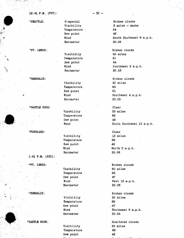
12:41 P.Y. (PST):
"SEATTLE :
- 32 - C-speoial Visibility Temperature Dew point Wind Barometer
"FT. LEWIS: Visibility Temperature Dew point Wind Barometer
"CHEHALIS :
"
"CASTLE ROCK:
"PORTLAND :
Visibility Temperature Dew point Wind Barometer
visibility Temperature Dew point Wind
Visibility Temperature Dew point Wind Barometer
1:41 P.H. (PST):
"FT. LEWIS: Visibility Temperature Dew point Wind Barometer
"CHEHALIS :
"CASTLE ROCK :
Visibility Temperature Dew point Wind Barometer
Visibility Temperature Dew point
Broken olouds 3 miles - smoke 54 45 South Southwest 9 m.p.h. 30.09
Broken clouds 60 miles 61 44 Southwest 3 m.p.h. 30.03
Broken olouds 30 miles 63 51 Southwest 4 m.p.h. 30.05
.Clear 30 miles 65 48 South Southwest 13 m.p.h.
Clear 12 miles 66 46 North 2 m.p.h. 30.06
Broken clouds 60 miles 65 47 Rest 12 m.p.h. 30.05
Broken clouds 50 miles 65 47 Southeast 5 m.p.h. 30.04
Scattered clouds 30 miles 66 48
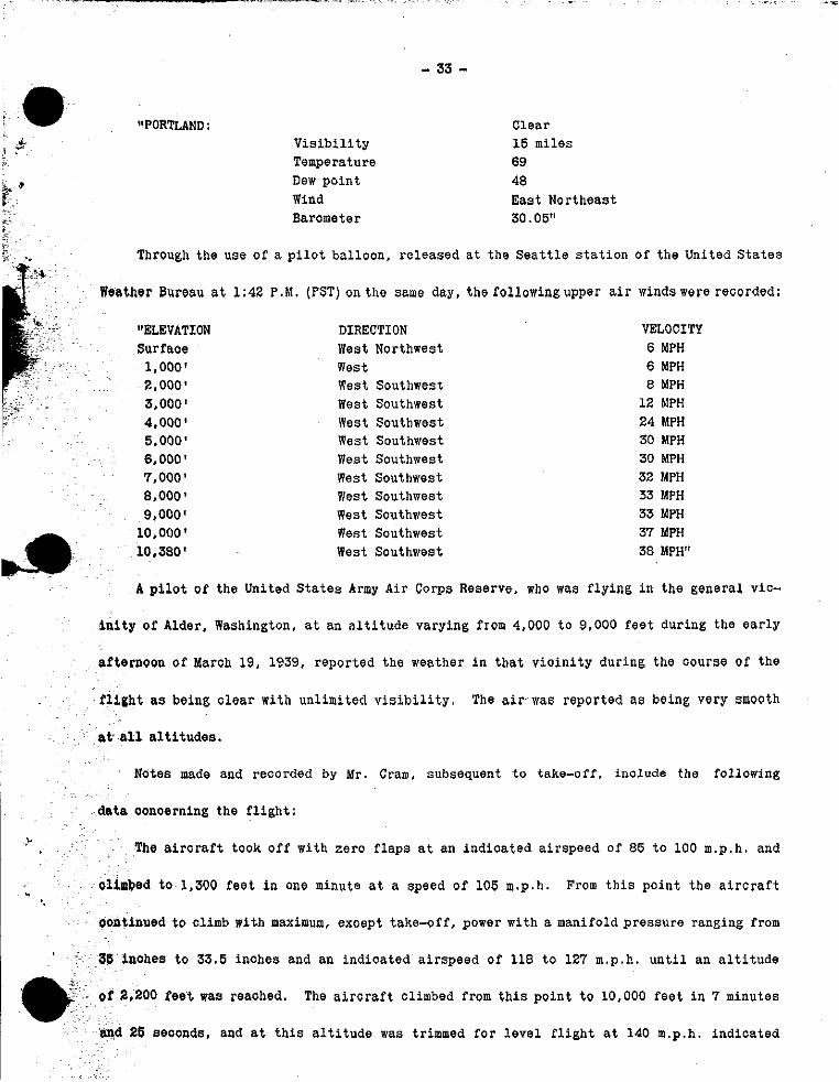
:. "PORTLAND : V i s i b i l i t y Temperature Dew po in t Wind Barometer
- 33 - Clear 15 miles 69 48 East Northeast 30.05"
37 MPH 38 MPH"
10,000' 10,380 '
Through the use of a p i l o t bal loon, re leased a t the S e a t t l e s t a t i o n of the United S t a t e s
Weather Bureau a t 1:42 P . M . (PST) on the szme day, the following upper a i r winds were recorded:
"ELEVATION DIRECTION VELOCITY Surfaoe West Northwest 6 MPH
1,000' West 6 MPH 2,000' west Southwest 8 MPH 3,000' West Southwest 12 hlPH 4,000' West Southwest 24 MPH 5,000' West Southwest 30 MPH 6,000' West Southwest 30 MPH 7,000' West Southwest 32 MPH 8,000' West Southwest 33 MPH 9,000' West Southwest 33 MPH
West Southwest West Southwest
A pi lo t of the United S t a t e s Army Air Corps Reserve. who was f l y i n g i n t he general vic-
Bnity of Alder, Washington, a t an a l t i t u d e varying from 4,000 t o 9,000 f e e t during t h e e a r l y
. af ternoon of Maroh 19, 1939, reported the weather i n t h a t v i c i n i t y during the oourse Of the
The air-was reported as being very smooth
~
f l l g h t as being olear w i t h unl imited v i s i b i l i t y .
at- a l l a l t i t u d e s .
Notes made and reoorded by Mr. Cram, subsequent t o take-off, include the following
da ta ooncerning the f l i g h t : I
% The a i r o r a f t took o f f w i t h ze ro f l a p s a t an ind ioa ted a i r speed of 85 t o 100 m.p.h. and
olinbed to 1,300 fee t i n one minute a t a speed of 105 m.p.h. From t h i s po in t t h e a i r c r a f t
continued t o olimb with maximum, except take-off, power with a manifold p re s su re ranging from
36'inOhes t o 33.5 inohes and an indioa ted a i r speed of 118 t o 12'7 m.p.h. u n t i l an a l t i t u d e
of 2,200 f e e t was reaohed. The a i r o r a f t climbed from t h i s po in t t o 10,000 f e e t i n 7 minutes
26 seoonds, and at t h i s a l t i t u d e was trimmed f o r l e v e l f l i g h t a t 140 m.p.h. ind ica ted
. '.
I - 34 -
c & up to 117 m.p.h. indicated airspeed, at which speed a control force at 8 pounds was necessary
to hold the aircraft in this attitude.
(The data to this point indicates that the purpose of the test above described was one
of static longitudinal stability determination as distinct from the dynamic longitudinal
stability tests which were apparently then started. The difference between the static
stability test and the dynamic stability test is that in the static stability test the stick
foroes and the elevator angles are measured at various airspeeds above and below trimmed
speed in statio condition; whereas, in the dynamic stability test, determinations are made
as to the action of the aircraft when left free to oscillate When trimmed in that Condition.)
The oontrols were released and as the aircraft oscillated freely in a longitudinal sense,
airspeed, with cruising Power at 1,900 r.p.m. and 23 inch manifold pressure.
'this oonditaon was 5' nose down and the control force was zero.
Tab setting for
The aircraft was then pulled .
readings were taken at 10-second intervals during such oscillations to determine the flight
path and the damping of the longitudinal oscillations. The zero pcsiticn was recorded as
the airoraft passed 100 m.p.h. indicated airspeed on its downward oscillation. At 10 seconds
the indicated airspeed was recorded as 115 m.p.h.; at 20 seconds, 120 m.p.h.; at 30 seconds,
110 m.p.h.; at 40 seconds, 100 m.p.h.; and, at 50 seconds, 110 m.p.h.
-* ti statio longitudinal stability test was then conducted, during which readings were
The speeds listed were 85, 80, 78. 75,
Nothing was written after
A
taken of the elevator control forces and positions.
and 72 m.p.h., with readings being entered after 85, 80 and 75.
78 or 72.
control force of 9 pounds was entered after 80 and of 10 pounds after 75 m.p.h.
The elevator positLon indicator read 395 at 85 and 80, and 400 at 75 m,p.h.
It is to be noted by reference to the flight plan for this flight that sideslips ccn-
stituted the next test to be Conducted.
At 1:12 P.M. (PST) a radio message was transmitted from NX 19901 to the Boeing Aircraft
Company radio Station located at Seattle, Washington, which message gave the position of the
airoraft as being between Tacoma, Washington and Mount Ranier at an altitude of 11,000 feet. ..
Some two o r three minutes later, while flying at a oomparatively slow rate cf speed in the ~
r~
5- .
&.
- ~ ____ ~ - ~ __ - 35 -
ViOinitY of Alder, Washington, t h e a i r o r a f t s t a l l e d and began t o s p i n i n a nose down a t t i -
tude . Af t e r oompleting two o r t h r e e t u r n s i n t h e s p i n , dur ing whioh power was appl ied , i t
reoovered from the s p i n and began t o d ive . The a i r o r a f t p a r t i a l l y recovered from the d ive
at an a l t i t u d e of approximately 3,000 f e e t above sea l e v e l . dur ing which reoovery i t began
t o d i s i n t e g r a t e . Outboard s e c t i o n s of t h e l e f t and r i g h t wings f a i l e d upward and broke en-
t i r e l y loose from the a i r o r a f t . Major p o r t i o n s of t he v e r t i c a l f i n and po r t ions of t h e rud-
d e r were c a r r i e d away by t h e wing wreckage. The outboard seo t ion of t h e l e f t e l e v a t o r sepa-
r a t e d from t h e s t a b i l i z e r and both f e l l t o t h e ground de tached . The r i g h t ho r i zon ta l t a i l
sur face . being he ld on by the f a i r i n g a long t h e t o p su r face and a l s o by the e l eva to r trim
t a b cables , remained with t h e fuse lage . The NO. 1 engine naoe l l e a l s o broke loose from the
a i r c r a f t and f e l l t o t he ground s e p a r a t e l y . The main body of t he a i r o r a f t s e t t l e d v e r t i c a l l y
and s t ruok t h e ground i n an almost l e v e l a t t i t u d e both l o n g i t u d i n a l l y and l a t t e r a l l y a t a
po in t approximately 1.200 f e e t above sea l e v e l . Watohes and c locks aboard the a i r o r a f t , whioh
were broken by foroe of t h e impaot, i nd ica t ed t h e time of t h e aooident as approximately 1:17
p.m. (PST).
Major component p a r t s of t h e a i r o r a f t , whioh broke loose i n t h e a i r s t ruok t h e ground
wi th respec t t o t h e fuse lage a s follows:
Left o u t e r wing panel, about 1,000 f e e t i n a southwesterly d i r e c t i o n ; r i g h t o u t e r wing
panel , about 530 feet i n a sou the r ly d i r e o t i o n ; l e f t outboard engine naoe l l e , about 660 f e e t
i n a sou theas t e r ly d i r e o t i o n ; l e f t ho r i zon ta l s t a b i l i z e r , about 200 f e e t i n a sou the r ly di-
r ec t ion ; and the l e f t e l e v a t o r outboard po r t ion , about 500 f t . i n a sou theas t e r ly d i r e c t i o n .
The g r e a t major i ty o f small parts were found wi th in the d i s t a n c e inoompassed by t h e looa t ion
of t he l a r g e r p ieoes from the fuse lage , though a few p a r t s were found a t a d i s t ance of 2,500
f e e t i n a sou theas t e r ly d i r e c t i o n .
Paraohutes of e i ther the s e a t o r ches t type were a v a i l a b l e f o r a l l persons aboard t h e
a i r o r a f t though were not being worn a t t h e time of t h e aooident.
The crash re su l t ed i n fa ta l i n j u r i e s t o a l l persons aboard the a i r o r a f t . J u l i u s Barr
was sea t ed i n t h e p i l o t ' s s e a t and A . G . von Baumhauer was s e a t e d i n the Go-pilot 's seat a t

- 36 - SPECIAL INSTRUMENTS
During the last four i’lights of NX 19901 a visual maximum indicating aooelerometer, the
purpose of whioh was to enable the pilot to know exactly the loading to which he was subjeot-
ing the airoraft during maneuvers and to prevent him from overloading the struoture, had been
installed on the airoraft. One hand of this instrument indicated at a11 times the normal
.~~ :.. _.. . .. i” ~ . r: .. .
i~
. * .
2 -; aooeleration to which the in,strument was being subjected while the other hand indicated the
maximnu aooeleration to which the instrument had been subjected since the hand was last set
back. This instrument *as removed from the wreckage of NX 19901 and forwarded to the manu-
faoturer for analysis. who reported that it had been subjected to an acceleration in excess
o f 10 g. the exaot amount of such excess being indeterminable. (This indicated acceleration
obviously ooourred at the time of impact with the ground. )
-corder - A V-G reoorder, owned by the National Advisory Committee for Aeronautics and lent to the
0 Boeing Aircraft Company, had been installed on NX 19901 during the early flight testing of
- the airoraft. This instrument traces, on a piece of smoked glass, a graph of the acoelera-
tlon encountered parallel to the vertical axis of the airoraft and the indicated airspeeds
o f the airoraft as the aooelerations ocour. This graph enables a determination to be made
of the maximum positive and negative aocelerations to which the airoraft had been subjeoted
.nd the indicated airspeed at which they occurred since that particular glass had been in-
c stalled in the reoordei.
During lateral stability tests on test flights N o s . 10 and 11 of NX 19901, a maximum
aooeleration of 1.7 e had been recorded at 230 m.p.h. indicated airspeed and a minimum of 0.2g
at 195 m.p.h. indicated airspeed. The normal value for steady unaooelerated level flight is
1.0 g. During similar tests on flight test NO. 12, which also inoluded climb, high speed runs
and stall tests, a maximum acceleration of 2.0 g occurred at.228 m.p.h. indicated airspeed
and the minimum of 0.4 g at 150 m.p.h. indicated airspeed. A maximum positive acceleration
- 37 - of 2 . 1 g and a minimum of 0 . 4 g were recorded dur ing d ive tests conducted on tes t f l i g h t No.
13 a t speeds I n excess of 320 m.p.h. i nd ioa ted a i r speed . whioh speed is t h e upper l i m i t of
t he range Of t h i s ins t rument . A s l i g h t discrepancy between t h i s instrument and t h e a i r speed
ind ioa to r was i n d i c a t e d dur ing t h i s test inasmuch as the l a t t e r instrument read 303 m.p.h.
a t the same time t h e V-G recorder i n d i c a t e d the speed above mentioned. No a c c e l e r a t i o n i n
excess of those encountered i n the prev ious tests were recorded dur ing take-off, landing,
speed run and s p i r a l s t a b i l i t y tests Conducted on t e s t f l i g h t No. 14, the only o t h e r f l i g h t
on whioh t h e instrument was u t i l i z e d .
The g l a s s i n t h e V-G recorder dur ing t e s t f l i g h t No. 19 was no t smoked and consequently
no graph was obta ined . Exhaustive s c i e n t i f i c tests f a i l e d t o revea l t he pa th of t h e in s t ru -
ment s t y l u s , and consequently no information whatsoever was revea led by t h i s instrument ccn-
cern ing t e s t f l i g h t No. 19.
Hor izonta l Accelercm&y
There was a l s o aboard NX 19901 a t the time of impact a ho r i zon ta l aocelerometer, t h e
purpose of which was t o record a c c e l e r a t i o n s along t h e f o r e and a f t a x i s of t he a i r c r a f t .
This instrument was badly damaged i n the c rash and subsequent examinat iondid no t revea l any
readings Which would i n d i c a t e t h e a c c e l e r a t i o n a t the time the a i r o r a f t d i s i n t e g r a t e d .
&&lOP;raDh
An osoi l lograph , the purpose of whioh was t o record engine v i b r a t i o n , was i n s t a l l e d cu
NX 19901 during t e s t f l i g h t No. 19 but was not i n ope ra t ion on t h i s f l i g h t .
AIRCRAFT ENGINES
An inspec t ion of t h e four a i r c r a f t engines subsequent t o disassembly revea led t h a t a l l
four had been badly damaged by impact with t h e ground, and t h a t c e r t a i n damage had occurred
during t h e f l i g h t , as the result of whioh the engines were i n t h e following cond i t ions p r i o r
t o impaot:
Engine No. 1 ( l e f t Outboard), S e r i a l No. 25030. which had fa l len t o t h e ground sepa ra t e
from t h e wing and the main body of t he a i rcraf t , had 44 hours and 40 minutes t o t a l opera t ing

.~
. * .
.: - I
e
r
'. '=*
- 38 - time. The t h r u s t n u t had soored the o i l seal r i n g bea r ing surfaoe of t he gear case t h r u s t
plate flange. dragging metal i n t o t h e r i n g grooves and t h u s s t i o k i n g a l l r ings . The region
of maximum sooring on t h e t h r u s t p la te f l ange was near t h e bottom and t o the r i g h t of t he
VertiOal Center l i n e , though t h e sooring continued e n t i r e l y around t h e surfaoe.
The s t i o k i n g of t he t h r u s t n u t r i n g s and the soor ing of t he o i l s e a l r i n g bea r ing sur-
f ace on the t h r u s t p l a t e r e s u l t e d from temporary misalignment of t he p r o p e l l e r s h a f t due t o
gyroscopic f o r c e s induced by preoession of t h e p r o p e l l e r during t h e s p i n and a t the time o f
pull-out from the d ive . The master rod bea r ing was burnished about 3/4 ' inch from each end.
(This condi t ion is normal i n engines whioh have run s e v e r a l hundred hours, bu t due t o the few
hours t h a t t h i s engine had been operated p r i o r t o impact, t h i s cond i t ion evidenoed ope ra t ion
at excessively high r.p.m.)
There was no i n d i c a t i o n of malfunotioning o r f a i l u r e o f t h e engine t o d e l i v e r r a t ed
power during normal f l i g h t .
Engine N O . 2 ( l e f t i nboa rd ) , Serial No. 25031, whioh had remained with the main body o f
t h e aircraft . had 45 hours and 10 minutes t o t a l ope ra t ing t ime. The f r o n t o i l s e a l r i n g
Of the t h r u s t nut was s l i g h t l y s tuok i n t h e groove and g e a r Case t h r u s t p l a t e f lange was
scored i n a manner similar t o t h a t on Engine No. 1 b u t t o a lesser degree and on t h e opposi te
side of t he s e a l o i l r i n g bea r ing su r face . This soo r ing was a l s o oaused bygyrosoopio f o r c e s
due t o precession of t h e p r o p e l l o r s during t h e s p i n and p u l l out from the dive. The master
rod bearing was i n good cond i t ion .
There was no ind ioa t ion o f malfunctioning o r f a i l u r e of t he engine t o d e l i v e r r a t e d power
during normal f l i g h t .
Engine NO. 3 ( r i g h t inboard) . S e r i a l No. 25032, whioh remained with the main body o f t h e
a i rcraf t , had 47 hours t o t a l ope ra t ing time. A l l o i l s e a l r i n g s of t h e t h r u s t n u t were s tuok
i n the grooves and the n u t had soored the o i l s e a l r i n g bea r ing s u r f a c e o f t he gear case
t h r u s t p l a t e f lange. The condi t ion o f each was i d e n t i o a l t o those of Engine No. 2 , and had
beenoausedbythesametypegyroscopicforoes as had been imposedon No. 1 and No. 2 engines.
- 39 -
e '
f
:
Some of t h e t e e t h on the pinion and s t a t i o n a r y gea r s were scu f fed and blued ind ica t ing
t h a t t he re had been a s h o r t per iod i n which they were out of alignment poss ib ly due t o the
same gyroscopic fo rces which had caused misalignment of the p rope l l e r s h a f t .
was s l i g h t l y scu f fed i n such manner as t o i n d i c a t e high r.p.m.
malfunctioning of t h i s engine o r f a i l u r e t o d e l i v e r r a t ed power during normal f l i g h t .
The cam bear ing
There was no ind ica t ion of
Engine No. 4 ( r i g h t ou tboard) , S e r i a l No. 25033, which had remained wi th the main body
of the a i r c r a f t had 42 hours and 25 minutes t o t a l opera t ing time. The t h r u s t n u t o i l seal
r ings were s tuok i n the grooves and the gear case t h r u s t p l a t e f lange was soored i n the same
manner as t h a t i n No. 2 engine. The condi t ion of the t h r u s t n u t and t h e t h r u s t p l a t e f lange
ind ica t ed that i n the case of these p a r t s the heat had been g r e a t e r , the t h r u s t p l a t e being
cracked around t h e f lange (poss ib ly due t o a g r e a t e r gyrosoopic foroe be ing app l i ed t o t h i s
engine).
The orank s h a f t was burnished and s l i g h t l y blued on the counter-weight s i d e of the orank
p in , which is evidence o f heat and excess ive r.p.m. The master rod bear ing was very s l i g h t l y
scuf fed and the re was evidence of some e tch ing of t h e bear ing m a t e r i a l . The bear ing metal
O f t he Gam bearing was s l i g h t l y e tched which fu r the r evidenced exoessive r.p.m. No Condition
was present which would i n d i c a t e f a i l u r e o f t h e engine t o d e l i v e r r a t ed power during normal
f l i g h t .
PROPELLERS
The prope l l e r s , a l l o f which were a t t ached t o the i r r e spec t ive engines , were found t o be
Gomplete w i t h no blades or p a r t s missing. The b l ades which were p a r t i a l l y bur ied i n t he ground
Were uncovered and the b lade angles a f te r impact, as ind ioa ted by t h e hub graduat ions , were
noted as follows:
Blade No. 1 Blade NO. 2 Blade No. 3 No. 1 Prope l l e r 330 2.80 100 No. 2 Prope l l e r 220 25O 2 7 O No. 3 Propel le r 339 70° 1700 No. 4 Prope l l e r 180 1 3 O - 1 7 O ( nega t ive angle)
- 40 - Eaoh p r o p e l l e r was removed from t h e engine and la te r disassembled and examined i n d e t a i l .
A l l b lades of each p r o p e l l e r were bent t o vary ing angles as a r e s u l t of impact w i t h t he ground.
P rope l l e r No. 1, hub S e r i a l No. 33543, had a t o t a l ope ra t ing time o f 44 hours and 10
minutes. No. 1 blade of t h i s p r o p e l l e r was sheared from its bushing toward the h igh p i t c h
angle approximately 25 degrees. Blade No. 2 was not sheared from its bushing. Blade No.
3 was sheared from its bushing toward the low p i t c h angle approximately 20 degrees . Other
than a dent i n t he dome t h e r e was no damage t o the hub assembly o r its opera t ing mechanism.
P r o p e l l e r No. 2, hub S e r i a l No. 37347, newly i n s t a l l e d , had a t o t a l opera t ing time c f
There was no f a i l u r e o f p a r t s i n the hub assembly and none of t he b lades were only 2 hours.
sheared from t h e i r bushings.
P r o p e l l e r No. 3, hub S e r i a l No. 33544, had a t o t a l ope ra t ing time of 47 hours and t h e r e
was no f a i l u r e of t he hub assembly p a r t s . Blade No. 1 was not sheared from its bushing.
Elade No. 2 was sheared from its bushing toward the high p i t c h angle approximately30 degrees.
Blade No. 3 was sheared from its bushing toward t h e high p i toh an;le approximately 130 degrees.
P rope l l e r No. 4, hub S e r i a l No. 33699, had a t o t a l opera t ing time o f 42 hours and 25
minutes. Blade No. 1 was sheared from its bushing toward high p i t c h approximately 4 degrees .
Blade No. 2 was sheared from i ts bushing toward the low p i t c h angle approximately 2 degrees .
Blade No. 3 was not sheared from its bushing, bu t t h e b lade gear segment was broken i n such
manner t h a t i t r o t a t e d toward low p i t c h . Mioroscopic examination of t he break i n the gear
Segment Showed tha t i t was due t o tennion and t h a t t h e r e was no s i g n of f a t i g u e o r d e f e c t i n
t h e material.
No oondition was found i n any of t he p r o p e l l e r s t h a t would i n d i c a t e any malfunctioning
dur ing normal f l i g h t . STRUCTURAL FAILURES
The p r i n c i p a l f a i l u r e s of t he s t r u c t u r e of NX 19901 and the na tu re and ex ten t of suoh
f a i l u r e s . a s ind ioa ted by exhaustive in spec t ion and a n a l y s i s of such f a i l u r e s , were as fo l -
lows:
* s i .
, '.
.. 41 - Right Wing
The i n i t i a l f a i l u r e s were a compression f a i l u r e i n t h e upper wing covering, compression
and bending f a i l u r e s i n the upper s p a r chords, t ens ion and bending f a i l u r e s i n the lower epar
chords and t ens ion f a i l u r e s i n the lower covering. The Outer panel o f the r i g h t Wing f a i l e d
upward near the j o i n t which connected the inner and outer pane l s . A s the outer panel f a i l e d ,
i t o a r r i e d the outer s e c t i o n o f t he r i g h t a i l e r o n w i t h i t . The inboard sec t ion from the
oon t ro l rod inboard, which was l e f t a t t ached t o the wing, la ter became detached w i t h a sec-
t i o n of the wing t r a i l i n g edge. The s e c t i o n of the upper covering between t h e s p a r s and be-
tween S t a t i o n 17 and S t a t i o n 21 were detached from t h e a l r o r a f t , though most of the covering
was still a t tached t o t h e aircraft .
As t h e ou te r panel moved upward a f t e r f a i l u r e , t h e aileron cab le s , which were j u s t be-
hind the rear spar , c u t through the Upper t r a i l i n g edge s k i n i n a s t r a i g h t l i n e p a r a l l e l t o
the spa r d i r e c t l y i n t o the body, t hus removing a l l support f o r t h e upper s i d e of t he t r a i l i n g
edge. A l l a i r l o a d s on t h e t r a i l i n g edge appear t o have been upward from the time the cables
out through t h e upper s k i n u n t i l t he a i r c r a f t reached the ground. ( T h i s is evidenced by t h e
f a c t that the c u t ends of the r i b s on t h i s upper su r face bu t t ed aga ins t t he spa r and t h e s p a r
cap, and t h e oonclusion t h a t any down load on the t r a i l i n g edge would have caused i t t o
break away from the a i roraf t . )
The marks of the a i l e r o n cables on the body o l e a r l y i n d i c a t e t h a t a s the r i g h t ou ter
panel swung upward still a t tached t o t he a i r c r a f t by means of t he two a i l e r o n cab le s , i t
swung over the body u n t i l i t occupied a p o s i t i o n t o the l e f t of and about t h ree foo t below
the top of t he f i n .
Lef t Wine. and Outboard Nacel le
The Outer l e f t panel f a i l e d upward between S t a t i o n 19 and S t a t i o n 13, whioh loca t ion is
f a r t h e r i n b o a r d t h a n t h e p o i n t of f a i l u r e o n t h e r igh twing , andoa r r i ed theen t i r ea i l e ron w i t h i t
as i t l e f t t h e a i r c r a f t . The f a i l u r e s of t he panel were oompressicn i n the upper covering
-42-
and i n the upper s p a r chords, t ens ion and bending failures i n the lower spa r chords and ten-
s ion and t e a r i n g i n the lower wing covering. As t he ou te r panel moved upward, the upper
oovering, which had not been f a i l e d as c l ean ly as on the r i g h t s i d e , peeled upward t o a po in t
j u s t inboard of the l e f t outboard engine nace l l e .
The upper support f o r the engine n a c e l l e , known as the upper ska te , r e s t s on top of t he
wing sk in and is bo l t ed t o the covering and ribs. I n pee l ing upward and inboard the wing
covering t o r e t h i s upper ska te loose from the wing, leav ing the engine and nace l l e supported
only by the inboard leading edge angle , the lower s k a t e a n d t h e connect ing tubes and c o n t r o l s .
The nace l l e , a s i nd ica t ed by the d i r e c t i o n i n which the r ivets i n t he lead ing edge sheared.
then f a i l e d forward and downward.
The s t r e n g t h of the covering and r i v e t s was g r e a t e r than the remaining s t r eng th of the
f ron t spa r , and as the covering moved upward it broke a s e c t i o n of t he s p a r i n t o seve ra l
p ieces . t h e l a r g e s t being a s e c t i o n of t he lower spa r chord about 6 f e e t i n length . The
rear s p a r was f a i l e d i n a similar manner.
The wing covering was broken i n t o a number o f p i eces , which ranged i n size from about
The f l a p was t o r n f r e e and was broken i n t o three f e e t by s i x fee t t o about one foot square.
four major p ieces , ranging frcm four f e e t t o s i x f e e t i n l eng th .
As the outer panel moved upward the a i l e r o n oables cu t through the upper sk in of the
t r a i l i n g edge p a r a l l e l t o the r e a r s p a r . One a i l e r o n cable then f a i l e d a t the body, and the
o ther cable , a f t e r f a i l i n g about 18 f e e t outboard from the body, rebounded inward, leaving
a mark along the body.
The upper SUrfaOe of the t r a i l i n g edge and the outboard h a l f of the lower su r face of the
t r a i l i n g edge of the l e f t wing were e n t i r e l y detached from the a i r c r a f t . A number of p a r t s
from the l e f t Wing s t ruck the body o f the a i r c r a f t , l eav ing marks which were s u b s t a n t i a l l y
along a l i ne from the wing t o the base of the f i n . Many of the marks were covered with al-
uminum pigmented P-27 primer with whioh the i n t e r n a l s t r u c t u r e of the wing was f in i shed .
. . ..I
9 . *
c
- 43 - . . . .. . .
The weight of t h e a i r c r a f t at t h e time o f t h e accident was approximately 42,500 pounds.
The aoce le ra t ion required t o cause complete f a i l u r e of t h e winges of t he a i rcraf t with t h i s
weight was est imated t o be 4.8g.
EiQ
The f i n was failed backwards and s l i g h t l y towards the r i g h t as the r e s u l t of impaot by
some p a r t of t he wing wreckage.
one-third of t he way up from the body, t h e f a i l u r e of t h e right-hand chord being somewhat
lower than the left-hand GhOrd. The r e a r s p a r was f a i l e d i n oompression, which f a i l u r e was
Gonsiderably g r e a t e r than the left-hand chord, i n d i c a t i n g t h a t t he loads which c a w e d t h e
failure were d i r e c t e d p a r t l y from the l e f t . (It is be l i eved that the f i n oould only be fail-
ed i n t h i s manner by loads a c t i x g near t he top o f t h e f i n i n a d i r e c t i o n almost s t r a i g h t t o
t h e rear. It is d i f f i c u l t t o conceive of any a i r l o a d of s u f f i c i e n t magnitude which would
cause the f i n t o f a i l i n t h i s manner,)
Both ohords of t h e f r o n t s p a r had t ens ion f a i l u r e s a b o u t -
f The upper one-third of the l ead ing edge of t h e f i n bore heavy marks, WhiGh appa ren t ly
were made hy the a i l e r o n cab le s from the r i g h t wing. As stated above, t hese cab le s oame ou t
of the body j u s t back of t h e rear spar and extended up and around the body of t h e r i g h t outer
panel. which was i n a p c s i t i c n t o t h e l e f t and below the top of t h e f i n . While i n t h i s posi-
t i o n , t he oables broke a t t h e i r i n t e r s e o t i c n with t h e body, snapping outward and s t r i k i n g
the leading edge of t he f i n about one-third of t he way from t h e top . They then s l ipped up
the leading edge of t he f i n t.c the p o i n t where the r ad io antenna f a i r l e a d , which was a t t ached
by means Of a 3/16" s t e e l t i e rod, extending through the t o p of t he f i n from t h e l ead ing edge
t o t h e rear spa r , came cut through t h e l ead ing edge of t h e f i n . -'A
The a i l e r o n cables . which had an u l t ima te t e n s i l e s t r eng th of approximately 10,000
pounds, pu l l ed t h i s t i e rod o u t of t he f i n about one-half way back t o the r e a r spar and out
away the t i p of t h e f i n which is loca ted above t h i s t i e rod. The t op of t h e f i n between t h e
leading edge and the r e a r spar.was a l s o f a i l e d i n compression. Af t e r pas s ing over t h e f i n ,
t he cab le s zlsc caught the upper rudder mass halanoe weight and scored t h i s weight t h e f u l l
l a n a t h nF i t - lcl*rlinrr arlns
- 44 -
1
I .
..I
The f i n a l s o was s t r u c k a heavy blow from the l e f t s i d e by the wreckage from the wings.
One member of t he s t r i k i n g ob jeo t en te red the f i n j u s t back of t h e l ead ing edge. and a f t e r
passing through t h e f i n , s t r u c k the right-hand chord of t he f r o n t s p a r , t e a r i n g c u t a sect ion
of t h i s spar ohord t o g e t h e r with its a t t a c h i n g s k i n . The upper two-thirds of t h e f i n was
broken e n t i r e l y c l e a r of t he a i r c r a f t b u t i t remained at taohed t o the mainbody o f t h e air-
c r a f t by means of rudder trim t a b c a b l e s which had pu l l ed o u t about 10 f e e t . These rudder
trim t a b cab le s oame back through t h e body and turned on p u l l e y s , supported by a bracket i n
t h e body below the base o f t he f i n , and ran d i r e o t l y up t h e r e a r s p a r of t he f i n . The brack-
e t i n t h e body was f a i l e d and t h e cables had cut i n t o t h e bulkheads i n t h e body near t h i s
bracket and also had c u t i n t o t h e seo t ion of t h e f i n whioh remained on the body. As indicat-
ed by a d d i t i o n a l marks down the center of t he rear f i n s p a r , made by t h e rudder trim t a b
oab le s , t h i s f i n spar was ben t approximately s t r a i g h t baok.
3!&sz
AS t he f i n moved backward i t forced the rudder, which was a t t ached t o t h e body and f i n
by means o f t h ree hinges on t h e f i n and two on the body, backward. As t he rudder was forced
baok, a f a i l u r e occurred i n the top body hinge (which i n d i c a t e s t h a t t he rudder was turned at
an angle of 20 degrees t o t h e r i g h t a t the time t h i s hinge was pu l l ed loose from the body
P o r t i o n ) . The h a l f of t h e top body hinge at taohed t o the bodj, was damaged very l i t t l e , being
ben t downward about one-half inoh (which f a c t l n d i o a t e s t h a t a t the time c f con tao t with the
ground. t he rudder was no t a t taohed t o t h i s h i n g e ) . The rudder c o n t r o l t a b was detaohed from
the rudder and along with a s e o t i o n of t he rudder was no t found subsequent t o the aooldent .
The piece of t he rudder whioh t o r e loose was one-half t he l eng th of t he control t a b i n l eng th
by about 18 inches deep and was normally looated immediately forward of t he top h a l f of t he
OOntro l t ab . The rudder appa ren t ly had been s t r u c k a heavy blow from the l e f t r e a r by some
part of t he wreokage. t he force of whioh was c a r r i e d i n t o t h e f i n . The s t u b of t he f i n re-
maining on the body had been s t r u c k twioe, t h e f i r s t blow coming from the f r o n t and l e f t and
-45-
bending the s t u b of t he f i n over toward t h e r i g h t and den t ing i t badly near t h e l e f t s i d e of
t he rear s p a r . T h i s blow appa ren t ly was s t r u c k by some f a i l e d pa r t of t h e i n t e r n a l s t r u c t u r e
from one of t h e wings, as t h e r e were marks on t h e f i n which had been made by t h e p r o t e c t i v e
c o a t i n g o f P-27 primer with which t h e i n t e r n a l s t r u c t u r e of t h e wlngs were f i n i s h e d . The
second blow, which came from the r e a r and the l e f t , a l s o s t r u c k the rudder and bent a s e c t i o n
of t h e f i n covering forward and over t h e s e c t i o n which was marked w i t h t he P-27 primer. This
p i ece of s k i n has a general shape of t he rudder torque tube and a l s o bore some marks made by
aluminumized dope (which f a c t i n d i c a t e s t h a t t h e blow probably drove t h e rudder torque tube
i n t o t h e f i n ) .
The rudder was broken i n t o two p i e c e s on a l i n e between t h e rudder c o n t r o l and trim tabs,
t he two p i e c e s being held toge the r only by t h e f a b r i c on t h e rudder. The rudder was he ld t o
the main body o f t h e a i r o r a f t by one of t h e s p r i n g Car t r idge l i n k s o f t he rudder c o n t r o l tab
and rudder con t ro l systems a t t h e lower end of t h e rudder . As t he f a i l u r e o f t he one s p r i n g
c a r t r i d g e l i n k assembly appeared t o have been caused when the main body of t h e a i r c r a f t made
oontaot with the ground, i t is p o s s i b l e that a t t h e time of Suoh con tac t with the ground i t
was held by both of t he s p r i n g c a r t r i d g e l i n k s . On con tac t with t h e ground, t h e lower end of
t h e rudder torque tube was dr iven about one foo t i n t o the ground, with the top po in t ing to-
ward the l e f t a t an angle of about 60 degrees. The remainder o f t he rudder was p r a c t i c a l l y
f l a t on t he ground along s i d e o f t h e lower p o r t i o n . The rudder mass balance weights which
were i n s t a l l e d approximately 12 f e e t apart, were dr iven i n t o t h e ground only fou r and one-
h a l f f e e t apart, both weights having f a i l e d d i r e c t l y a t r i g h t a n g l e s t o the rudder torque tube.
The rudder trim tab remained a t t ached t o the rudder.
bdx As t he main body of t he a i r c r a f t made con tac t with t h e ground i n an almost l e v e l posi-
t i o n - both l o n e i t u d i n a l l y and l a t e r a l l y i n v e r t i c a l descent , t h e e n t i r e fuselage s t r u c t u r e
f a i l e d downward, breaking completely through i n cross-section a t t h r e e p o i n t s . The upper
po r t ion of t he p re s su re bulkhwd i n t h e r e a r part of the body buckled toward the f r o n t por-
t i o n Of t he fuselage. As f a r as could be determined, no damage was done t o the body while
- 46 -
...
e
.. ' h
t h e a i r c r a f t was i n t h e a i r , except f o r t h e con t ro l cab le marks on the r i g h t s i d e of t he body
a s above desor ibed . There was no evidence of power be ing app l i ed by t h e engines a t t h e time
of impaot wi th t h e ground.
Stabilizers and E l e v a t o s
Both t h e s t a b i l i z e r s and e l e v a t o r s f a i l e d upward, and, a s % a s ind ica t ed by the Symmetry
o f t he f a i l u r e s on both s i d e s of those su r faces , both as t o type and loca t ion of t h e f a i l u r e s ,
t hese t a i l su r f aces were apparent ly symmetrically loaded a t t h e time of such f a i l u r e s . The
f a i l u r e s i n t h e s t a b i l i z e r f r o n t s p a r upper chords cons i s t ed of t h e r ivets a t t ach ing t h e hinge
f i t t i n g s t o the spar chords being sheared by loads a o t i n g inward. The upper spar chords
made deep symmetrical den t s i n t he body on t h e i r r e spec t ive s i d e s . The lower f r o n t s t a b i l i -
zer spa r ohords f a i l e d i n t ens ion , the one on t h e l e f t f a i l i n g i n t h e s t e e l hinge terminal,
and the one on t h e r i g h t f a i l i n g i n t h e s p a r chord j u s t outboard of t h e s t e e l hinge terminal.
The f a i l u r e s i n t h e r e a r s p a r s were similar t o t h e f a i l u r e s i n t h e bottom chords i n t h e f r o n t
wars. . . . . . . . .. ~ ... ~ ~ . .. ... ~. .~ ~. ~
.The e l eva to r torque tube , as ind ioa ted by the inward f a i l u r e o f t he r i v e t s a t t a c h i n g the
outboard flanged oouplings t o t he outboard elevator torque tube , and t h e outward fa i lure of
those on the bottom sides, f a i l e d i n bending on both s i d e s o f t h e a i r c r a f t at t h e po in t where
t h e outboard e l eva to r torque tubes a r e jo ined t o t h e s e o t i o n of t h e torque tube which passes
through the body of t he a i r c r a f t . The outboard torque tubes , which f i t over t he male por-
t i o n s of t h e flanged oouplings, f a i l e d by s p l i t t i n g along t h e tops o f ' t h e torque tubes length-
wise of t h e tubes .
The l e f t e l eva to r was broken i n t o two p ieces , t h e outboard f a i l u r e ooouring i n the nose
s e c t i o n of t h e e l eva to r formed by the e l e v a t o r channel s e c t i o n s p a r and the leading edge sk in
j u s t outboard of t he poin t where t h e heavy torque tube ends wi th in t h e e l e v a t o r . The f a i l u r e
was due t o t o r s i o n and bending, wi th bending predominating. As t h e s t a b i l i z e r s and e l e v a t o r s
were de f l ec t ed upward under the a c t i o n of t h e upward a c t i n g loads , t h e e l e v a t o r s moved out-
- 47 - board with relation to the stabilizers due to interaction of the stabilizers and elevators.
This relative mction bent the elevator ends of the hinge brackets attached to the stabilizers
outboard, and caused the hinge brackets on the left stabilizer to tear loose from the stabil-
izer, while those on the right-hand stabilizer showed only a slight evidence of such inter-
action between the stabilizer and elevator. Though the top half of the leading edge of the
left-hand outboard section of the elevator had been cut into deeply by the elevator hinge
brackets, there was only a slight indication that the hinge brackets had contacted the bottom
half of the leading edge portion of this part of the left elevator. Both pieces of the left
elevator were ripped from the left stabilizer. The trim tab of the left elevator was intact
on the outboard part of suoh elevator and was set approximately in neutral, while part of the
oontrol tab, including its statio balance weight, was found on the inner portion of the
left elevator. The torque tube of the left elevator control tab had failed at the side o f
the body at the coupling. The left stabilizer and both pieces of the elevator were detached
from the aircraft.
The leading edge section of the right-hand elevator, at the point just outboard of the
end of the elevator torque tube, showed evidence cf the same type of failure as that which
ooourred at this location in the left elevator leading edge section. However, as is eviden-
ced by the faot that the elevator torque tube and both stabilizer spars were driven directly
into the ground about 18,inches, the right stabilizer and left elevator weie in a vertical
position at the time of contact with the ground. There also were permanent wrinkles in the
right-hand elevator just outboard of the point where the heavy torque tube ends within the
elevator, which wrinkles had been caused by a rotation of the elevator in the up direction
due t o the aoticn of torsion about the elevator hinge line. The right-hand elevator and its
trim and oontrol tabs were intact when the aircraft struck the ground, though the elevator
OOntrOl tab operating torque tube was failed at the side of the body. Holes which had been
punched through from top to bottom in the trailing edge of this elevator were apparently
oaused by the elevator having contacted %hat was left of the vertical control surfaces after

-48-
t h e r i g h t s t a b i l i z e r and e l e v a t o r had f a i l e d upward. The e l e v a t o r hinge b racke t s a l s o had
out deep gashes i n the lower h a l f of t h e r i g h t e l e v a t o r nose s e c t i o n a t a l l hinge .po in ts .
The right-hand s t a b i l i z e r and e l e v a t o r were he ld on t o t h e body O f the a i r c r a f t at t h e time
of impact by t h e l e f t s t a b i l i z e r f a i r i n g s t r i p and by two 3/32” e l e v a t o r trim t a b cont ro l
Oables.
. % Insnec t ion
A very d e t a i l e d inspec t ion of t h e body, a l l working p a r t s which remained w i t h the air-
o r a f t , and a l l c o n t r o l cab le s f a i l e d t o revea l any ind ica t ion of malfunctioning o r f a i l u r e
prior t o d i s i n t e g r a t i o n of t h e a i rc raf t , which would have accounted f o r l ack of o r l o s s o f
oon t ro l . A l l f u e l l i n e s and t h e e n t i r e f u e l system were a l s o thoroughly inspec ted and no in-
d ioa t ion of stoppage i n t h e f u e l l i n e o r f a i l u r e p r i o r t o d i s i n t e g r a t i o n of t h e a i r c r a f t was
found. A l l con t ro l su r f ace balance weights were accounted fo r i n the v i c i n i t y of t h e main
-- ,%,
body of t he aircraft , and in spec t ion o f such weights revea led tha t a l l conformed t o speci-
f i c a t i o n s . The p o s s i b i l i t y o f sabotage was considered and inves t iga t ed thoroughly, bu t no
evidenoe was found t o i n d i c a t e t h a t i t was involved i n t h i s acc iden t .
w!s It i s of interest i n oonneotion wi th t h e facts hereinabove enumerated that records are
a v a i l a b l e ind ica t ing t h a t a i rcraf t of t h e same general type and des ign as NX 19901 have been
spun on two occasions. I n t h e f i r s t of t hese exper iences , an a i r c r a f t of t h e same genera l
dimensions and des ign as the Model 307, with t h e exception o f t h e fuse lage , while f l y i n g w i t h
a gross load of about 42,000 pounds a t an a l t i t u d e of 14,000 f e e t , went i n t o an inadver ten t s p i n
and made two complete t u r n s before recovery was e f f e c t e d . During t h e pull-out from t h e en-
’. su ing d ive , permanent d i s t o r t i o n occurred i n t h e s t r u c t u r e of both wings , n e c e s s i t a t i n g the
z
i n s t a l l a t i o n of new wings on t h e a i r c r a f t .
I n the second o f these experiences, a similar s h i p was i n t e t i o n a l l y permi t ted t o e n t e r
a sp in following a complete s ta l l . The cont ro ls were immediately reversed and t h e a i r c r a f t
responded promptly, enabling t h e p i l o t t o e f f e c t recovery a f t e r t h ree - fou r ths of a tu rn i n
- 49 - Evidence indicated that power was used i n recovery from the spin i n t h e case of NX 19901.
It should be noted that i n the two instances above desoribed recovery from spin i n s imilar
a ircraf t was accomplished without the employment O f power. I n one of these cases , permanent
distort ion occurred i n both wings.
* >
- 50 - . _. :. . .. SUMMARY OF FINDINGS
1. A i r c r a f t NX 19901, Boeing Model S 307, met the p e r t i n e n t requirements s e t f o r t h i n
Seot ion 01.3 of t he c u r r e n t l y e f f e o t i v e C i v i l Air Regulations and was proper ly i s sued an ex-
perimental c e r t i f i o a t e by t h e C i v i l Aeronautios Authority.
2. NX 19901 had only been opera:ed experimentally by the Boeing A i r o r a f t Company and
had never been mbmit ted t o the C i v i l Aeronautics Authority f o r f i n a l i n spec t ion and f l i g h t
tests required p r i o r t o c e r t i f i c a t i o n as t o its a i rwor th iness .
3 . The cu r ren t ly e f f e c t i v e experimental c e r t i f i c a t e i ssued on a i r o r a f t NX 19901 by
the C i v i l Aeronautios Authority au thor ized f l i g h t of t he a i r c r a f t a t a maximum take-off weight
of 45,000 pounds and a maximum landing weight of 41,000 pounds. The c e r t i f i c a t e p roh ib i t ed
the oar ry ing of passengkrs and r e s t r i o t e d f l i g h t personnel t o bona f i d e members of t he crew.
4 . A i r o r a f t NX 19901 crashed near Alder, Washington, a t approximately 1 : 1 7 P.M. (PST),
Saturcay, March 10, 1939, v i t h t he r e s u l t a n t d e s t r u c t i o n of t he a i r o r a f t and f a t a l i n j u r i e s
t o a l l persons aboard.
5. The weather i n the v i o i n i t y o f Alder, Washington, at the time of the acc ident was
The upper a i r was very smooth wi th a moderate west south- c l e a r with unlimited v i s i b i l i t y .
west wind p r e v a i l i n g a t a l t i t u d e s above 2000 f e e t .
6. P i l o t J u l i u s Barr held a cu r ren t ly e f f e c t i v e Commercial C e r t i f i c a t e of Competency
i ssued by the C i v i l Aeronautics Authority wi th appropr ia te r a t i n g s f o r t he f l i g h t here in
involved. Bar had a t o t a l f l y i n g time on NX 19901 p r i o r t o t e s t f l i g h t No. 19 of one hour
and 52 minutes as observer ; 17 hours and 55 minutes as oo-pilot; and, 2 hours and 6 minutes
as f irst p i l o t . The remainder of h i s f l y i n g time i n four-engine a i r c r a f t oons is ted of 3
hours and 6 minutes as observer , and 9 hours and 17 minutes a s oo-pilot on the Boeing Model
314.
'I I Co-Pilot Ea r l Ferguson he ld a ou r ren t ly e f f e c t i v e Commeroial C e r t i f i c a t e of Com-
petency i ssued by the C i v i l Aeronautics Authority w i t h appropr i a t e r a t i n g s fo r t h e f l i g h t
here in involved. Ferguson had a t o t a l f l y i n g time on t h e Bceing Model S 307 p r i o r t o t e s t
. *
4
J J.
- 61 - f l i g h t NO. 19 of 4 hours and 52 minutes as co-pi lot . The remainder of h i s f l y ing time i n
f o u r e n g i n e a i r c r a f t cons is ted of 9 hours and 15 minutes as co-pi lot on the Boeing Model
Y1B-17A; 2? hours and 57 minutes as observer ; 18 hours and one minute as co-pi lot , and 16
hours and 39 minutes as p i l o t of t he Boeing Model 314.
8 . Albert G. von Baumhauar he ld a p r i v a t e p i l o t ' s license i ssued on November 28. 1931
by the Dutoh Air Minis t ry , the records of which show t h a t h i s t o t a l f l y ing time as p i l o t
amounted t o 116 hours . He had no experience a s p i l o t o r co-pi lot of four-engine a i r c r a f t ,
bu t had been observer i n t r i a l f l i g h t s of fou r engine FoWer F 22 and F 36 a i r c r a f t . He
ocoupied the co -p i lo t ' s seat and was se rv ing as co-pilot i n a i r c r a f t NX 19901 a t the time Of
t he aooident .
9. The performance of a i r c r a f t NX 19901 on f l i g h t s p r i o r t o t e s t f l i g h t No. 19 had
e i t h e r met o r exceeded the manufacturer ' s estimates.
10. The main oont ro l sur faoes were mass balanced dur ing tes t f l i g h t No. 19 as below
indica ted :
The rudder had 104 percent static balance accomplished by means o f a 17 pound weight
at the top of the rudder, loca ted 24.2 inches ahead of t he hinge l i n e and a 50 pound weight
on an arm a t the body oenter l i n e 24 .2 inches ahead of t he rudder hinge l i n e . This gave
a ooe f f io i en t of dynamic balance of 0.028 with respec t t o the rudder hinge l i n e and the
oenter l i ne o f the body. The rudder con t ro l tab was not s t a t i c a l l y balanced.
The e l e v a t o r had 55.2 percent s ta t ic balance acoomplished by means of a 60 pound weight
looated 21.4 Inches ahead o f the e l e v a t o r hinge l i n e and on the body c e n t e r l i n e . T h i s gave
a ooe f f i c i en t of dynamio rralance f o r each ha l f of the e l e v a t o r s of 0.10 n i t h respec t to the
elevator hinge l i n e and the cen te r l i n e of t he body. The e l e v a t o r c o n t r o l t abs were s t a t i c -
a l l y balanoed.
The ailerons were 18.7 percent s t a t i c a l l y balanced based on t h e i r a c t u a l s t r u c t u r a l
weight d i s t r i b u t i o n and t h e r e were no mass balance weights incorpora ted . Each a i l e r o n had a
OOeffiCient of dynamic balanoe of 0.292 with respec t t o its hinge l i n e and the c e n t e r of the
- 52 - The a i r o r a f t w i t h t h e foregoing con t ro l surfaoe mass balanoing was dived i n a f l i g h t
t e s t previous t o test 19 t o an ind ica t ed a i r speed o f 303 miles p e r hour with no evidence of
f l u t t e r , though t h e adequacy of suoh balanoing had no t been determined under varying oon-
d i t i o n s of f l i g h t .
11. The o r i g i n a l mass balanoing o f t he e l e v a t o r s incorporated a 74.3 pound weight.
During t h e e a r l y f l i g h t t e s t s of a i roraf t NX 19901, t h i s weight was reduced t o 60 pounds i n
o r d e r t o ob ta in an inorease i n the oen te r of g r a v i t y range wi th in whioh the a i r c r a f t was
l o n g i t u d i n a l l y s t a b l e .
A f u r t h e r reduotion i n t he e l e v a t o r mass balanoe wiezht from 60 pounds t o 50 pounds was
made on t e s t f l i g h t Nos. 16, 17 and 18 i n an attempt t o f u r t h e r inorease t h e range of oen te r
of g rav i ty . During the dive, i n reoovering from a s ta l l on t e s t f l i g h t No. 18, mild f l u t t e r
developed a t an i n d i c a t e d a i r speed of 240 miles per hour. Following t h i s experience, t h e 50
pound e l e v a t o r mass balanoe weight was replaoed with t h e 60 pound weight f o r test f l i g h t No.
19.
As 303 miles p e r hour was the design g l i d i n speed f o r t h i s a i r o r a f t , no t e s t s were '
1 I
i made t o determine a t what speed i n excess of 303 miles p e r hour f l u t t e r might occur with the
60 pound e l eva to r mass balanoe weight.
I 12. During the s ta l l tests of t h i s a i r o r a f t , t h e r e was a s ta l l warning o c n s i s t i n g of a
c h a r a o t e r i s t i o bu f fe t ing of t h e wings and c o n t r o l su r f aoes a t i nd ioa ted a i r speeds from 5 and
8 miles per hour with power o f f and from 1 t o 2 miles p e r hour with power on f a s t e r than
t h e speed a t whioh t h e a o t u a l s tall ooourred. Recoveries from a l l stalls conduoted on f l i g h t s
P r i o r t o t e s t f l i g h t No. 18 were begun immediately af ter the nose of t he a i r c r a f t began t o
drop. Under these condi t ions, t he nose was no t permit ted t o f a l l below l e v e l f l i g h t posi-
t i o n before reoovery was s t a r t e d , t he result o f whioh was the l o s s of 200 t o 600 f e e t a l t i -
tude i n e f f e o t i n g reoovery. The a i r o r a f t showed no tendency t o f a l l o f f on e i t h e r wing
during suoh stalls.
I
I
I
!
- 53 - Stall tests were conducted on test flight No. 18 by Harlan Hull, of Transcontinental
and Western Air, Inc. During some of these tests Mr. Hull completely stalled the aircraft j I
and permitted the nose to drop below level flight positions before recovery was started.
Under these conditions there was no tendency of the aircraft to spin and recovery was normal.
13. The notes made by Mr. Cram on test flight No. 19 indicated that the take-off was
normal and that the olimb up to 11,000 feet altitude, using rated engine power, had been made
in a normal manner. At this altidude longitudinal stability tests were made and the notes
indioated that this phase of the flight test was nearing oompletion, if not actually ccm-
pleted. The next tests, as outlined by the previously approved flight plan, were side-slip
1 .!
tests.
14. At the request of Mr. von Baumhauer, Who Occupied the Co-pilOt'S seat Of NX 19901
at tne time of the accident. two special instruments were installed on the aircraft. One
instrument was installed on the oo-pilot's control oolumn to be used for measuring the forces
in pounds required to operate the elevators during specific maneuvers. It would be neoessary
tc operate the airoraft with the oo-pilot's controls in order to obtain readings from this
instrument. The second instrument, which was mounted on top of the instrument panel in front
of the oo-pilot. was connected to the control cables of the ailerons. rudder and elevators
for the purpose of indicating the amount of movement of these controls during various man-
euvers.
15. The flight plan covering test flight No. 19 was based upon specific requests made
Dy Mr. von Baumhauer for the purpose of determining whether o r not this aircraft would meet
the flight charaoteristics desired by the Dutoh Air Ministry. Although this flight test was
intended to include tests set forth in the flight plan, it was also a demonstration of the
aircraft tc representatives of the Dutch Air Ministry, Royal Dutch airlines and Transccn-
tinental and Western Air, Inc.
16. All pertinent evidence indicated that the airoraft went into an inadvertent spin
subsequent to a stall at an altitude of approximately 11,000 feet. It made two to three
4
j I
i i ! i
i
\
- 54 - t u r n s i n the s p i n , during which the engines were used t o a id recovery. In recovering from
the d ive subsequent t o t h e s p i n , t h e wings and ho r i zon ta l t a i l s u r f a c e s fa i led upward appar-
m t l Y due t o a i r loads i n excess of t hose f o r which t h e a i rcraf t was designed.
* I
” .. -. -
17. There is no oonclusive evidence as t o which wing f a i l e d f i r s t o r whether t he Wings
f a i l e d before the ho r i zon ta l t a i l su r faces . The l e f t e l e v a t o r f a i l e d about 3 f e e t outboard
O f t he s i d e of t h e body, such f a i l u r e being due t o bending and to r s ion i n t h e e l e v a t o r nose
s e c t i o n w i t h bending predominating. The outboard s e c t i o n of t he l e f t e l e v a t o r was torn loose
from the stabil izer and t h e condi t ion of t he hinges i n d i c a t e d t h a t its movement had been UP-
ward and outward w i t h respeot t o the s t a b i l i z e r . I n d i c a t i o n s are t h a t t h i s was t h e f i r s t
f a i l u r e whioh oocurred i n t he ho r i zon ta l t a l l s u r f a c e s and tha t i t was followed by the separ-
a t i o n o f t he l e f t s t a b i l i z e r and the inne r po r t ion O f t he l e f t e l e v a t o r from the body. The
r i g h t s t a b i l i z e r and e l e v a t o r were sub jec t ed t o and f a i l e d by fo rces similar t o those which
f a i l e d the l e f t ho r i zon ta l t a i l su r faces . These surfaoes, however, remained a t t ached t o the
body by means Of t he upper fa i r ing and the e l e v a t o r trim tab c a b l e s .
The v e r t i o a l t a i l s u r f a c e s failed as a r e s u l t of being s t r u c k by par ts of t he broken
wings.
trim tab cables .
The upper po r t ion of t h e rudder and f i n remained a t t aohed t o the body by the rudder
18. A v e r t i c a l accelerometer had been mounted on the instrument panel t o i n d i c a t e t o
the p i l o t t he acce le ra t ion t o which t h e a i r c r a f t was being sub jec t ed i n order t h a t dangerous
s t r e s s e s due t o exoessive a c c e l e r a t i o n could be avoided.
. 19. A V-G recorder , t he p rope r ty Of t he Nat ional Advisory Committee f o r Aeronautics,
The glass i n s t a l l e d i n t h i s instrument
. was installed on NX 19901 during t e s t f l i g h t No. 19.
I’
2.
on t h i s f l i g h t had no t been smoked, and consequently the re was no record of t he maximum in-
dioated a i r speed a t t a i n e d o r t he v e r t i o a l a c c e l e r a t i o n s encountered during t h i s f l i g h t .
20. The weight o f t he a i r c r a f t a t the time o f t he acc iden t was approximately 42,500
pounds. The a c c e l e r a t i o n required t o cause complete f a i l u r e cf the wings on the a i rc raf t
w i t h t h i s weight was est imated t o be 4.8g.
- 65 - 21. An oscillograph was installed on NX 19901 for the purpose Of recording engine vi-
brations, but was not in operation during test flight No. 19.
22. Examination of the engines and propellers subsequent to disassembly disclosed noth-
ing which indicated failure to deliver rated p0we.r prior to impact.
23. Each person aboard the aircraft on test flight No. 19 had a paraohute of either
the seat or chest type available for his use.
24. Flight tests conducted with NX 19901 indicated that the Control forces required to
maneuver this airoraft were light in comparison with other four-engine aircraft of comparable
weight and design.
25. On aprevious test flight (No. 13) employing the same control surfaoe mass balanoe
weights used during flight No. 19, there was qo indication of flutter at the design gliding
speed of 303 miles per hour which was attained during a shallow dive in smooth air. NO
high speed dive tests were run under varying atmospheric conditions to determine whether
flutter might develop at less than the designed gliding speed if executed in turbulent air,
26. Stalls and spin tests conducted with airoraft, oomparable to the Boeing Model
307 in size and design, do not indicate with any degree of finality the characteristics of
such airoraft in these maneuvers.
-
* * * *
In addition to the faots, Conditions and OirGumstanOes presented above, the following
known and potential factors may have -contributed to the accident although evidence to this
effect is not conclusive: I
! I I
1. Assignment of a first pilot inexperienoed in testing and demonstrating airoraft of
this type, particularly with respect to the maneuvers called for on test flight No. 19.
2. Inexperience on the part Of M r . yon Baumhauer, who was serving as Go-pilot, in the
I handling of this aircraft in maneuvers being conducted at his request.
3. A test flight of the aircraft involving demonstration of maneuvers which had not
~
previously been investigated thoroughly. 1 1
- 66 - 4. Inexperienoe with the r ad ioa l d i f fe renoe i n s t a l l c h a r a c t e r i s t i c s of t h e a i r o r a f t
p a r t i c u l a r l y i n view of the p r o b a b i l i t y t h a t the a i r c r a f t was not completely s t a l l e d during 1
tests oonducted with the 17" up-elevator t r a v e l .
I With 25' up-elevator t r a v e l as compared with the 1 7 O up-elevator t r a v e l previously used, 1
t o over-control e a s i l y , and thus change the a t t i t u d e of t he a i r c r a f t so abrupt ly as t o i m -
pose s t r e s s e s exoeeding those f o r which the a i r o r a f t was designed o r would withstand.
. * .
J - 6 . Elevator f l u t t e r i n the d ive , following recovery from the sp in , which may have dev-
eloped, because c f inadequate mass balancing of t h e e l e v a t o r s , a t an a i r speed i n excess of
t he designed g l id ing speed of the a i r c r a f t .
( F l u t t e r developing during t h i s maneuver might have inf luenced the p i l o t i n reocvering !
i on t h e rudder and the l o s s of the a s s i s t ance of the con t ro l t ab , r e s u l t i n g i n the i n a b i l i t y
of the p i l o t t o exe r t s u f f i c i e n t fo rce upon t h e c o n t r o l s t o prevent sp ins . I
8 . I n s u f f i c i e n t v e r t i c a l t a i l sur faces , as p resen t ly designed and installed, t o give i i adequate cont ro l of the a i r c r a f t under a l l condi t ions o f f l i g h t .
* * I *
Sketohes showing t h e probable f l i g h t path and maneuvers of the a i r c r a f t during its
descent ; r e l a t i v e loca t ions of parts of t h e a i rcraf t subsequent t o impact with the ground;
and t h e main s t r u c t u r a l f a i l u r e s p r i o r t o impact w i t h the ground, a r e a t tached here to and
marked Exhib i t s "A", "B", and "C", r e spec t ive ly , and a r e by referenoe made a p a r t of t h i s .
repor t . c * * * I
PROBABLE CAUSE
. S t r u o t u r a l f a i l u r e c f the wings and hor izonta l t a i l su r faces due t o t he imposition of 1
I I I l oads thereon i n excess of those f o r which they were designed, t h e f a i l u r e cocurr ing i n an
abrupt pull-out from a d ive following recovery from an inadver ten t sp in .
* * * I
- 57 - RECOMMENDATIONS
A s t he r e s u l t of i t s i n v e s t i g a t i o n of t h i s a m i
t h a t :
1. The C i v i l Aeronautics Authority make:
- n t . t he Air Sa fe ty Board recommer
a . A f u r t h e r s tudy of t h e mass balancing of a l l c o n t r o l su r f aces o f the Boeing
Model 30'7, as p r e s e n t l y designed and i n s t a l l e d , fo r t he purpose o f determining its
adequacy i n a l l r e s p e c t s before i s s u i n g a type c e r t i f i c a t e f o r t h i s a i r c r a f t .
b . S tud ie s f o r t h e prevent ion o f f l u t t e r in c o n t r o l su r f ace t a b s on a l l a i r c r a f t
by proper mass balancing of t hese u n i t s o r by s a t i s f a c t o r y mechanical means i n the event
of l a g o r f a i l u r e i n t h e ope ra t ing mechanism.
C . Continued s t u d i e s of t h e f a c t o r s which cause or con t r ibu te t o f l u t t e r and vi-
b r a t i o n of a i r o r a f t s t r u c t u r e s , and t h a t t he r e s u l t s o f a l l such s t u d i e s be made ava i l -
a b l e t o the i n d w t r y and minimum requirements based thereon be included i n t h e C i v i l
Air Regulations.
2. The C i v i l Aeronautics Authority make a s tudy of t h e Boeing Model 30'7 t a i l group,
p a r t i c u l a r l y t o determine the adequacy of t he attachment f i t t i n g s of both f ixed and movable
component p a r t s .
3. The C i v i l Aeronautics Authori ty:
a. Make a f u r t h e r s tudy of t h e s ta l l and s p i n o h a r a o t e r i s t i o s of t h e Bceing 307
by such f l i g h t and o t h e r tests as may be required f o r t he purpose of determining the'
e f f e c t i v e n e s s and tidequaoy of its design i n the prevent ion o f c r i t i c a l s talls a n d s p i n s ,
and in recovery therefrom. Should t h e r e s u l t s of such s t u d i e s and t e s t s prove t h e
c h a r a c t e r i s t i c s t o be unsa t i s f ac to ry , it is recommended t h a t c o r r e c t i v e measures b e t a k e n
p r i o r t o the issuance of a type Cer t iS ioa te on t h i s model a i r c r a f t .
~ ~ ~ .~ __--- - ~.~..~ . .. ~ - -~ ~' ~
~ .. , -~ b. Require a l l f u t u r e c i v i l a i r o r a f t t o be s o designed as t o e l imina te c r i t i c a l
s ta l l c h a r a c t e r i s t i c s and be inhe ren t ly spin-proof.
i - 58 - 4. The Civil Aeronautics Authority expedite the development of an adequate st.al1 warn-
ing device. It is further recommended that suoh device, when developed, be a required in-
stallation on all air carrier airoraft. <-
. ~ --__ - 5. In addition to any other similar studies, the Civil Aeronautics Authority require
extensive wind tunnel tests on soale models of all aircraft designed for air carrier service
and submitted for type certificate and that the results of suoh tests to be submitted to the
Civil Aeronautics Authority f o r review and approval. It is further recommended that the spin
characteristics of such aircraft be determined in so far as possible through the use of a
spin-tunnel.
6 . The Civil Aeronautics Authority thoroughly investigate the tendenoy in certain large
airoraft designs to so reduce the forces required to operate the Controls as to permit undue
stresses being imposed inadvertently on the aircraft.
7. Thorough study be made by the Civil Aeronautios Authority to determine the adequacy
of the mechanism employed on the adjustable oockpit windows of the Boeing Model 307, parti-
cularly as to the satisfactory functioning of this mechanism under severe ioing oonditicns
and the visibility provided under such circumstances.
8 . The Civil Aeronautics Authority consider the advisability o f increasing present I
maneuvering-load-factor requirements fo r large aircraft. i
I 9. The Civil Aeronautics Authority investigate the adequaoy of the differential between
the design level speed. the placarded "never-exceed-speed," and the design gliding speed Of I
the Boeing Model 307. to give reasonable assurance that the aircraft can be controlled within i
these design limits under adverse flying oonditions and that loads beyond its designed struc- 1
tural strength will not be imposed under operating conditions in turbulent air.
I
i
I
. I 1 I
10. The Civil Aeronautios Authority require determination of the design loading for
tail surfaces on a basis which takes into account the definitely oalculated effeot of gusts
and maneuvers on the total loads imposed and their distribution.
!. '.,
- 59 -
Q 11. (a] The Civil' Aeronautios Authority require as a provision of experimental certi-
fioates that a V-G recorder be installed on all aircraft intended for air carrier use and
that the record obtained from it be preserved and made a part of eaoh flight test report.
It is further recommended that a complete record of all flight tests be submitted to the
Civil Aeronautics Authority prior to test flights oonducted by the Authority in ccnnection
with the granting of a type oertifioate.
(b) An aocelerometer be installed in full view of the pilot during all flight tests,
and that a limit mark be plaoed on the instrument to represent the maximum acceleration to
whioh it is safe to subject the aircraft. It is further reoommended that such an aCCelW0-
meter be made a required installation on all air oarrier aircraft, and that all readings ob-
tained in flight exceeding an amount to be speoified by the Civil Aeronautics Authority for
each particular type aircraft be reported to the Civil Aeronautics Authority together with a
desoription of the oircumstanoes, (i.e., indicated air speed, altitude, air conditions, eto.
under whioh the acoeleration was obtained.
- -__-------..--- ~ .~ . .. ~ ~.. .--..--
(0) An immediate study be made looking toward the development of adequate vibration
reoorders, taking into oonsideration the size and capaoity of various model aircraft and fie-
quenoies whioh would include the entire range of vibration and flutter affecting their StrUC-
ture and control. As such reoorders beoome available, it is recommended that aircraft manu-
faoturers be required to install them and make the data so obtained a part o f the reoord of
all phases of the experimental test flight program.
12. The Civil Aeronautics Authority establish by regulation uniform and more adequate
test flight procedures for aircraft intended to be used in air carrier servioe. It is spec-
ifically recommended that such test flights include all maneuvers in whioh the airoraft might
become involved inadvertently under turbulent air o r other conditions to be anticipated in
a i r oarrier service. It is further recommended that the test flight procedure include com-
plete Stalls from straightaway flight and high angle sideslips both in turbulent air and
under oonditions of unavmetrioal power.
- 60 - 13. The C i v i l Aeronautics Authori ty by regula t ion es tabl ish a s p e c i a l r a t i n g for t e s t
p i l o t s of large a i rcraf t and r equ i r e a l l t e s t f l i g h t s o f a i r c r a f t i n t h i s category, p r i o r t o
issuance of a type cer t i f icate , t o be conducted by p i l o t s holding such c e r t i f i c a t e s .
* I * *
Studies and research are being continued i n connection w i t h c e r t a i n t echn ica l phases of
t h i s accident which may requi re a supplemental r epor t and add i t iona l recommendations a t a
^ I 6 .
c - la ter d a t e . *
BY DIRECTION OF THE BOARD
Executive Of f i ce r
f
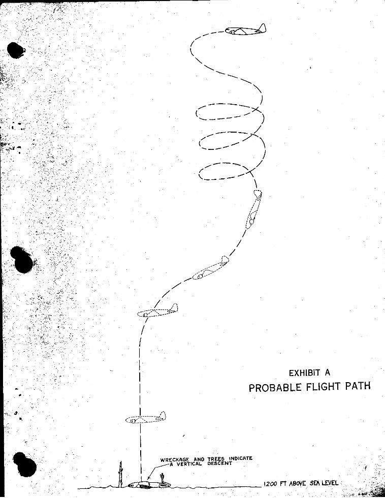

1