Embed Size (px)
Citation preview

C A R B O N 4 9 ( 2 0 1 1 ) 4 4 3 4 – 4 4 4 2
. sc iencedi rec t .com
avai lab le at wwwjournal homepage: www.elsev ier .com/ locate /carbon
One-pot synthesis of MnO2/graphene/carbon nanotube hybridby chemical method
Ying Chen a,b, Yong Zhang a, Dognsheng Geng a, Ruying Li a, Hanlie Hong b,Jingzhong Chen b, Xueliang Sun a,*
a Department of Mechanical & Materials Engineering, Faculty of Engineering, The University of Western Ontario, 1151 Richmond Street,
London, Ontario, Canada N6A 3K7b Engineering Research Center of Nano-Geomaterials of Ministry of Education, China University of Geosciences Wuhan, 388 Lumo RD, Wuhan
430074, China
A R T I C L E I N F O
Article history:
Received 15 January 2011
Accepted 10 June 2011
Available online 6 July 2011
0008-6223/$ - see front matter � 2011 Elsevidoi:10.1016/j.carbon.2011.06.046
* Corresponding author.E-mail address: [email protected] (X. Sun
A B S T R A C T
A branched hybrid of MnO2/graphene/carbon nanotube (CNT) is generated in a one-pot
reaction process by chemical method. Some ultrathin MnO2/graphene nanosheets, around
5 nm in thickness, are randomly distributed on the CNT surface. Morphology, phase struc-
ture, microstructure and vibrational properties of the hybrid were characterized by field
emission scanning electron microscope, X-ray diffractometer, high resolution transmission
electron microscope and Raman spectrometer. Elemental distribution of the hybrid was
determined by energy dispersive X-ray mapping performed in scanning transmission elec-
tron microscope mode. The key factor of the formation mechanism is associated with both
redox and oxidation–intercalation reactions. Graphene flakes are partly exfoliated from the
surface layers of the CNTs, and the redox reaction between KMnO4 and hydroxyl groups
occurs on both sides of these flakes, resulting in the formation of a MnO2/graphene/CNT
hybrid. Brunauer–Emmett–Teller surface area measurements indicate that the hybrid has
over four times the specific surface area of the pristine CNTs.
� 2011 Elsevier Ltd. All rights reserved.
1. Introduction
Graphene and carbon nanotubes (CNTs) have driven numer-
ous applications in electronics due to their outstanding phys-
ical and chemical properties [1–3]. Benefiting from their
superior electrical conductivity, high electrochemical stabil-
ity, good mechanical properties and high specific surface
area, both graphene and CNTs are considered as ideal rein-
forcing components in fabricating complex nanostructured
hybrids and composites, thereby tailoring properties of vari-
ous nanostructured devices.
Manganese oxide (MnO2) is a widely used material featur-
ing low-cost, high energy density, environmental pollution-
free and nature abundance [4,5]. Recently, much efforts have
er Ltd. All rights reserved).
been focused on the synthesis of nanoscale MnO2/CNT
(graphene or porous carbon) hybrids due to their significant
electrochemical applications [6–10], such as supercapacitors
and lithium ion batteries. However, there are still some chal-
lenge to be overcome such as increase of the mass loading on
the surface of substrate, effective control of the thickness of
MnO2 films. Generally, MnO2 deposits readily form planar
nanosheets on flat substrates, resulting in the reduced sur-
face area of substrates and thick MnO2 layers coating [11].
For MnO2/CNT composites, Reddy et al. [10] synthesized the
coaxial hybrid of MnO2 and CNTs leading to enhanced Li stor-
age properties. In their further work, they [12] fabricated Au
segmented MnO2/CNT coaxial arrays which showed improve-
ment in specific capacitance, energy and power density
.

C A R B O N 4 9 ( 2 0 1 1 ) 4 4 3 4 – 4 4 4 2 4435
because of their good electrical contacts between electrode
and current collector. Lee et al. [13] obtained MnO2/CNT com-
posite with well-controlled ultrathin MnO2 films with an
approximate thickness of 5 nm. This value is in agreement
with nanoscale MnO2 which could provide high specific
capacitances. The design and fabrication of MnO2/CNT com-
posites with three-dimensional multifunctional architectures
make the MnO2 sheets grow along radial direction from the
walls of CNTs, which is another possible way to dissolve men-
tioned problems [14]. Zhang et al. [15] found that MnO2 tends
to nucleate at the junctions of CNTs and then grow radically
from junctions. These MnO2 nanoflowers/CNTs arrays are
composite with hierarchical porous structure. Xia et al. [16]
pre-treated CNTs with KMnO4 in neutral conditions to form
small nanocrystals of MnO2 on the CNT walls, and then the
nanocrystals continuously grew into nanoflaky via a hydro-
thermal process. The key factor of formation of nanflaky/
CNTs composites is that the nanocrystalline MnO2 on walls
of CNTs serves as the nucleation site. Using graphene as the
carbon support, Yan et al. prepared graphene/MnO2 by micro-
wave irradiation. The graphene sheets serve as high conduc-
tive support, which provide the large surface for the
deposition of nanoscale MnO2 particles. Wu et al. [17] mixed
MnO2 nanowires with graphene sheets by solution-phase
assembly. Presence of MnO2 nanowires on the surface of
graphene prevents the stacking of graphene due to the van
der Waals interactions, while on the other hand, the high con-
ductivity of graphene is favorable to improve the dispersion of
MnO2 nanowires and the electrical conductivity. To the best of
our knowledge, controlled synthesis and detailed structural
scrutiny of MnO2/graphene/CNT ternary hybrid have not been
reported yet.
In this paper, we report a versatile chemical reaction pro-
cess for fabricating a kind of three-dimensional hybrid of
MnO2/graphene/CNT nanostructures. At the low level of oxi-
dation, oxygen-containing groups increased without MnO2
nanocrystallines formed. The defects on the walls of CNTs
is favorable to intercalation of SO2�4
- and peeling off of graph-
ene. Afterwards, the partly exfoliated graphene came from
the walls of CNT matrix, with the ultrathin MnO2 sheets coat-
ing on the surface of graphene sheets instead of CNTs. Via
strong van der Waals interaction of the un-exfoliated walls
and MnO2 film coating on the graphene and CNTs, the petal
sheets of MnO2/graphene could stand on the CNT matrix sta-
bly. Careful engineering of hybrid reached over four times the
specific surface area of the pristine CNTs.
2. Experimental
2.1. Synthesis of multi-wall carbon nanotubes
The multi-wall carbon nanotubes (MWCNTs) in this work
were synthesized by an aerosol-assisted chemical vapor
deposition method (Supplementary data Fig. S1). At the begin-
ning, a porcelain substrate was placed in a quartz tube, in
which an argon flow (200 sccm) was passed through to purge
the system for 20 min. Then the furnace was heated to 900 �Cwithin 15 min. As soon as the temperature at the center of the
furnace reached 900 �C, an aerosol (solution containing 11 g of
ferrocene (FeCp2) in 500 ml of m-xylene) was generated ultra-
sonically and carried by mixed gas flow of argon A (40 sccm),
hydrogen (60 sccm) and argon B (45 sccm, dilute gas) into the
quartz tube, and meanwhile water vapor was introduced into
the reactor by another flowing argon (40 sccm) through a
water bubbler during the growth period. After 30 min of reac-
tion, the ultrasonic sprayer was turned off and argon A was
stopped. Hydrogen, water vapor and argon B flow were kept
passing through the reactor until the furnace cooled down
to room temperature.
2.2. Synthesis of MnO2/graphene/CNT hybrids
In a typical procedure, MWCNTs (10 mg) were ground with
KMnO4 (100 mg, Aldrich) crystallites by using a mortar and
pestle to a powder mixture. This mixture was then suspended
in 10 ml de-ionized (DI) water and stirred at room tempera-
ture (22 �C) for different time of 1–12 h. After that, a trace
amount of concentrated H2SO4 (50 ll, Aldrich, 95–98 wt.%)
was introduced into the system and the stir continued at
room temperature for additional 60 min. Afterwards, the
solution was heated in an oil bath at 80 �C for 60 min. The
reaction mixture was then removed from the heat source,
and poured into 500 ml of DI water to cool down and dilute.
The solution was filtered over a polytetrafluoroethylene
membrane (0.22 lm pore size, Aldrich), and the remaining so-
lid was washed repeatedly with DI water for several times.
2.3. Sample characterization
Morphology of the hybrid was characterized by field emission
scanning electron microscope (FESEM, Hitachi S-4800). Phase
structure of the hybrid was characterized by Bruker D8 micro
X-ray diffraction (XRD), operating at 40 kV and 40 mA, with Cu
Ka radiation (k = 0.15418 nm). High resolution investigation of
the hybrid was performed with transmission electron micro-
scope/scanning transmission electron microscope (TEM/
STEM, JEOL 2010F) equipped with an Oxford INCA Pentafet
spectrometer (Oxford Instruments, Abingdon, Oxfordshire,
UK). The acceleration voltage was 200 keV. Energy dispersive
X-ray mapping (EDX) was performed in STEM mode with a
probe size of 1 nm. Raman spectra were collected using Ra-
man Rxn1-785 spectrometer (Kaiser Optical Systems, Inc.)
Brunauer–Emmett–Teller (BET) surface area was measured
by N2 physisorption at 77 K using a Micromeritics ASAP
2010. Fourier transform-infrared (FT-IR) measurements were
carried out by the KBr method using a Nicolet 6700 FT-IR spec-
trometer. FT-IR spectra were recorded in the transmittance
mode over the range of 500–4000 cm�1 by averaging 16 scans
at a resolution of 4 cm�1.
3. Results and discussion
Fig. 1A and C shows FESEM images of the hybrid, with the
morphology of reticular and curved petal-like walls on the
carbon nanotubes with originally smooth surface over the en-
tire longitudinal length. Fig. 1B and D depict corresponding
TEM images of inherent structure of the petals-tube hybrid,
displaying a long-range array of transparent petal-like sheets

50 nm
B
50 nm
D
A
C
Fig. 1 – (A–D) SEM and TEM characterization of a representative MnO2/graphene/CNT hybrid.
4436 C A R B O N 4 9 ( 2 0 1 1 ) 4 4 3 4 – 4 4 4 2
attached upon the sidewalls of the inner nanotubes with the
size of �280 nm. Interfacial profiles between the petals and
the tube can be well distinguished. A BET surface area test
shows that specific surface area of the hybrid is 143 m2 g�1,
C
5 nm
A
10 20 30 40 50 60 70
Inte
nsity
(a.u
.)
2θ (degree)
110
CN
T
211
301
510
521
002
541
600
20 30 40 50 60
Fig. 2 – (A) XRD patterns of pristine CNTs (inset) and the hybrid.
High-resolution TEM (HRTEM) image obtained from a curved edg
presenting a over four times the specific surface area of the
pristine carbon nanotubes (32 m2 g�1).
We used XRD analysis to determine the phase structure of
the hybrid Fig. 2A. An evident peak at the 2h value of about
D
3.05 Å
3.10 Å
5 nm
B
500 1000 1500 2000 2500
500 1000 1500 2000 2500
Inte
nsity
(a.u
.)
Raman shift (cm-1)
1312
1580
2607
649
575
(B) Raman spectra of pristine CNTs (inset) and the hybrid. (C)
e of the hybrid. (D) HRTEM image of a single petal-like sheet.
C A R B O N 4 9 ( 2 0 1 1 ) 4 4 3 4 – 4 4 4 2 4437
26.05� is in consistent with (0 0 2) crystal plane of graphite.
Other characteristic peaks with marked crystal faces can be
assigned to the tetragonal phase of a-type MnO2 (JCPDS 44-
0141) [18,19]. We also used Raman spectroscopy to investigate
vibrational properties of the hybrid Fig. 2(B). Intensity ratio of
D to G band (Id/Ig) increases accordingly from 1.53 to 2.77 with
the oxidation reaction progress, indicating the enhanced level
of disorder within the product and the formation of sp3 car-
bon by functionalization. In addition, two sharp, low fre-
quency bands at about 575 and 649 cm�1 can be used to
characterize the tunnel species of a-type MnO2 materials,
which are commonly attributed to the Mn–O stretching vibra-
tion in the basal plane of MnO6 sheet, and the symmetric
stretching vibration Mn–O of MnO6 groups [20,21]. Moreover,
the edge of a representative petal-like sheet Fig. 2C was ascer-
tained by high-resolution TEM, showing the thickness below
5 nm and counted with four layers or less considering the
stacking possibility of two or more curving sheets. Two lattice
fringes with the spacing 0.305 and 0.310 nm Fig. 2D can be in-
dexed as (1 3 0) and (3 �1 0) crystal planes of a-type MnO2,
respectively, which is consistent with XRD and Raman
observations.
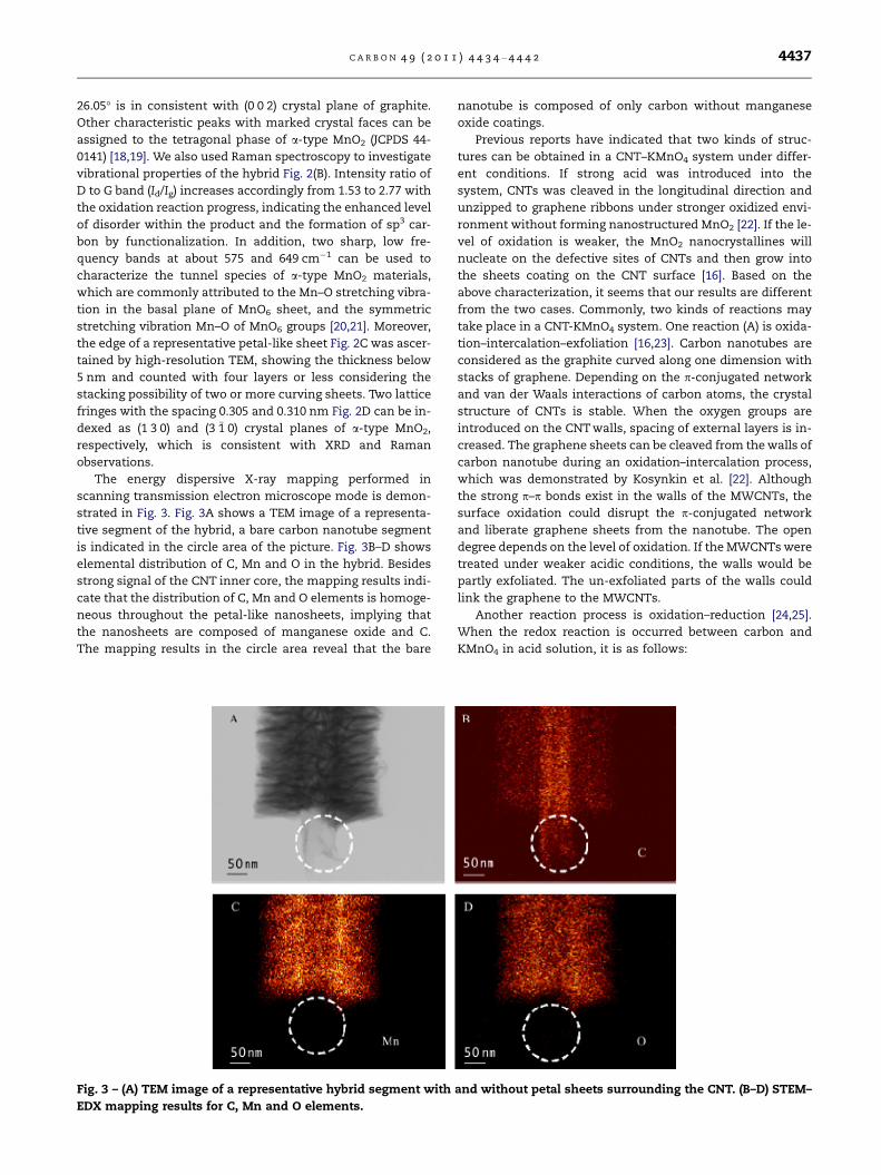
The energy dispersive X-ray mapping performed in
scanning transmission electron microscope mode is demon-
strated in Fig. 3. Fig. 3A shows a TEM image of a representa-
tive segment of the hybrid, a bare carbon nanotube segment
is indicated in the circle area of the picture. Fig. 3B–D shows
elemental distribution of C, Mn and O in the hybrid. Besides
strong signal of the CNT inner core, the mapping results indi-
cate that the distribution of C, Mn and O elements is homoge-
neous throughout the petal-like nanosheets, implying that
the nanosheets are composed of manganese oxide and C.
The mapping results in the circle area reveal that the bare
Fig. 3 – (A) TEM image of a representative hybrid segment with
EDX mapping results for C, Mn and O elements.
nanotube is composed of only carbon without manganese
oxide coatings.
Previous reports have indicated that two kinds of struc-
tures can be obtained in a CNT–KMnO4 system under differ-
ent conditions. If strong acid was introduced into the
system, CNTs was cleaved in the longitudinal direction and
unzipped to graphene ribbons under stronger oxidized envi-
ronment without forming nanostructured MnO2 [22]. If the le-
vel of oxidation is weaker, the MnO2 nanocrystallines will
nucleate on the defective sites of CNTs and then grow into
the sheets coating on the CNT surface [16]. Based on the
above characterization, it seems that our results are different
from the two cases. Commonly, two kinds of reactions may
take place in a CNT-KMnO4 system. One reaction (A) is oxida-
tion–intercalation–exfoliation [16,23]. Carbon nanotubes are
considered as the graphite curved along one dimension with
stacks of graphene. Depending on the p-conjugated network
and van der Waals interactions of carbon atoms, the crystal
structure of CNTs is stable. When the oxygen groups are
introduced on the CNT walls, spacing of external layers is in-
creased. The graphene sheets can be cleaved from the walls of
carbon nanotube during an oxidation–intercalation process,
which was demonstrated by Kosynkin et al. [22]. Although
the strong p–p bonds exist in the walls of the MWCNTs, the
surface oxidation could disrupt the p-conjugated network
and liberate graphene sheets from the nanotube. The open
degree depends on the level of oxidation. If the MWCNTs were
treated under weaker acidic conditions, the walls would be
partly exfoliated. The un-exfoliated parts of the walls could
link the graphene to the MWCNTs.
Another reaction process is oxidation–reduction [24,25].
When the redox reaction is occurred between carbon and
KMnO4 in acid solution, it is as follows:
and without petal sheets surrounding the CNT. (B–D) STEM–

4438 C A R B O N 4 9 ( 2 0 1 1 ) 4 4 3 4 – 4 4 4 2
4KMnO4 þ 3Cþ 2H2SO4 ! 4MnO2 þ 3CO2 þ 2K2SO4 þ 2H2O
In this reaction, the graphene sheets serve as the sacrificial
reductant and convert the Mn+7 to Mn+4 and thereby nano-
structured MnO2 are produced. As Yan et al. [11] reported,
synthesis of MnO2 nanocrystals was promoted through the
rapid nucleation on the graphene surface under microwave
irradiation with short reaction time, and the MnO2 particles
dispersed at the edges of graphene layers. In our experiments,
the high ratio of KMnO4 to CNTs promoted the oxidation of
the CNT walls instead of nucleation of MnO2, which is differ-
ent from the previous research about the mechanism of
three-dimensional MnO2/CNT nanocomposites by Xia et al.
[16]. In order to explore the role of KMnO4 and H2SO4 during
the growth of hybrid, some control experiments were carried
out.
Fig. 4 shows the TEM images and Fourier transform infra-
red (FT-IR) spectroscopy of CNTs treated only with KMnO4 be-
fore heat (Fig. 4a), and images of the CNTs treated with
KMnO4 and different amount of H2SO4 (Fig. 4c–e). Comparing
Fig. 4 – (A) TEM image of CNTs treated with KMnO4 in water for
for 3, 6, 9 h, respectively, TEM image of the CNT treated with KM
to the pristine CNTs, as shown in Fig. 4a, the CNT walls kept
smooth without any MnO2 nanocrystals observed when the
nanotubes were only treated by KMnO4. And we used FT-IR
spectroscopy to track the functional groups on the surface
of KMnO4-treated MWCNTs (Fig. 4b). The spectra of the trans-
formed MWCNTs illustrate the presence of the C@O (uC@O at
1640 cm�1), C–OH (uC–OH at 1380 cm�1) and the COOH/OH
(uCOOH/OH at 3400 cm�1) [22]. With incremental exposure of
the MWCNTs to KMnO4, these characteristic peaks stepwisely
increase and broaden except the peak at 1380 cm�1, the
C–O–C (uC–O–C at 3400 cm�1) stretch appears in sample a–c,
indicating an increase number of carboxyl and hydroxyl
functionalities. All these functional group changes reveal that
oxidation degree of the final MWCNTs is remarkably depen-
dent on the KMnO4 pre-treatment time. There is no observa-
tion of nanoscale MnO2.
In order to obtain further information of initial growth of
MnO2 and the exfoliation from CNTs, detailed high resolution
TEM studies were carried out.
9 h; (B) FT-IR spectrum of CNTs treated with KMnO4 in water
nO4 and, (C) 50 ll; (D) 2 ml; (E) 10 ml H2SO4.

C A R B O N 4 9 ( 2 0 1 1 ) 4 4 3 4 – 4 4 4 2 4439
Fig. 4c shows the TEM image of the initial growth of the hy-
brid based on the CNTs treated with KMnO4 and low amount
of H2SO4 (50 ll), same as the conditions of the sample shown
in Fig. 1. The areas marked by the dotted border indicate that
some petals were (about 10 nm long) partly exfoliated from
the CNT, and the petals were surrounded by MnO2. When
high amount of H2SO4 was used, the longitudinal unzipping
of the nanotubes instead of MnO2 deposition was observed
as shown in Fig. 4d (2 ml of H2SO4,) and Fig. 4e (10 ml of
H2SO4).
Based on the above results, it indicates that the structure
control of the hybrid in our work is expected to be dominated
by a competition between the two reactions of oxidation–
intercalation–exfoliation and oxidation–reduction processes,
and the growth of MnO2/graphene/CNTs hybrid is proposed
in this work by carefully controlling the growth parameters.
To get further insight into the structure of the hybrid, we
ever adopted a general method to remove the excess of per-
manganate and MnO2, sufficient amount of hydrogen perox-
ide (H2O2) and a solution of HCl in water (1:10 v/v dilution
from commercial concentrated HCl) were added and then
the samples were washed by large amount of distilled water
repeatedly. Fig. 5a shows TEM image of the samples after
reduction, revealing that the spatial architecture of the sam-
ple is satisfyingly maintained. We used Raman technique to
investigate the vibrational properties of the treated samples.
Comparing to the samples without treatment, the Raman re-
sult shows the obvious change of characteristic peaks which
belong to the MnO2. The peak located at 649 cm�1 disappears
and the density of peak at 575 cm�1 is decreased, indicating
Fig. 5 – (A, B) SEM and TEM images of, (C) Raman s
that the large amount of MnO2 nanocrystals were destroyed
after treatment. Furthermore, the density of the multi-band
peaks around 2607 cm�1 (2D) are increased obviously, which
is consistent with the multi-layer feature of graphite because
of decrease of MnO2 amount. This is also supported by the
SEM–EDX results. The EDX reflects the mass loading of
MnO2 from 33% down to 5% (the range is 5–10%). It is still dif-
ficult to observe the details of their microstructure directly
owing to the complexity of samples which are consisted of
CNTs, MnO2 and graphene-like carbon. Due to the coating
of residual MnO2 on the graphene-like petal sheet, and the
3-D architecture is stable even under stir or ultrasonic treat-
ment. The presence of MnO2 limited the characterization of
the quality of the graphene sheet directly, even after the treat-
ment of the samples with HCl and H2O2 to destroy the large
amount of MnO2 nanocrystals. Due to the non-uniform exfo-
liation of CNTwalls and consumption of exfoliated graphene,
the final state of graphene sheets can be: (1) completely exfo-
liated graphene sheets; (2) partly exfoliated graphene sheets
attached on the CNT; (3) a sacrificial reductant and exhausted.
Besides dose of H2SO4, the morphology of MnO2 of the
composites also strongly depended on reaction temperature
and reaction time. Generally, higher temperature or longer
reaction time would favor the gain of petal sheets formed.
Keeping other optimized conditions the same, morphology
and size of the carbon/MnO2 sheets were able to be readily
modulated by adjusting each one of the three factors. Here
dependence of the hybrid morphology on the temperature is
taken as the example. Fig. S3 shows low and high magnifica-
tion SEM images of the hybrids processed at 40, 60 and 80 �C,
pectrum of samples after HCl and H2O2 treated.

4440 C A R B O N 4 9 ( 2 0 1 1 ) 4 4 3 4 – 4 4 4 2
respectively, demonstrating stepwise growth of the petal
sheets. At low temperature of 40 �C, the CNTs surface still re-
mains relatively smooth except some corrugated structures.
With the increase of the temperature, corrugated structure
becomes entangled network and finally develops into the
cross-linked petal-like structure on the CNT surface. The
amount of H2SO4 had to be controlled as low as 1 ml, other-
wise carbon/MnO2 sheets would be peeled off from CNTs
(Fig. S4). Moreover, the CNTs would be unzipped in the longi-
tudinal direction under large amount of H2SO4. The treatment
time of H2SO4 also needs to be carefully tuned to make the
oxidation process more controllable. Long treatment time in
the presence of H2SO4 could lead to the break of the hybrids
into short segments (Fig. S5).
Depending on preparation processes, different carbon
materials may exhibit different microstructures and proper-
ties, such as defects on surface, specific surface area and elec-
trical conductivity. Therefore, we tried some usual carbon
materials with the identical process, including graphene
sheets, commercial MWCNTs with different diameters, flake
graphite and spherical-like acetylene black which seem to
be formed by graphene sheets in the scroll geometry. For
the growth of the MnO2 on the graphene sheets (Fig. S6), both
flat and flower like structure can be found due to the differ-
ence among the local surface conditions of the graphene
sheets. This indicates that MnO2 is expected to be uniformly
deposited on the graphene nanosheets depending on the
Fig. 6 – Schematic diagram of a proposed mechanism for the e
experimental conditions and quality of the graphene sheets.
The morphologies of the received products grown on com-
mercial MWCNTs and flake graphite substrates are similar
to those grown from the MWCNTs in this work. We could ob-
serve the presence of a densely crossed array of the free-
standing nanosheets with different size and curved shape
in our samples with the commercial CNTs, and flake graphite
inside (Figs. S7 and S8). However, in the case for acetylene
black, the original carbon source exhausted and resultant
hierarchical structure with hollow center was obtained. The
low resolution SEM and TEM images (Fig. S9) of as-received
samples show uniform changes of their morphologies and
high yields. Besides few of the separate samples, most of
which was still aggregated, being determined by the separate
particles or aggregated chains of starting materials. TEM-EDX
of single petal sheet shows the obtained sample is composed
of four elements, namely C, K, Mn and O. This is different
from the previous research on KMnO4–acetylene system [8],
in which just MnO2 nanostructures were obtained and the
carbon source was released by generating CO2 gas completely,
revealing that large amount of carbon atom are composited
with MnO2 during the experimental process.
Thus, we suggest the following mechanism of the MnO2/
graphene/CNT ternary hybrid demonstrating in the sche-
matic as shown in Fig. 6: (1) on the initial stage, KMnO4 is
mixed with CNTs in a neutral condition. The large amount
of KMnO4 acts as a ‘‘weak oxidizing agent’’ due to much less
volvement steps from CNTs to MnO2/graphene/CNT hybrid.

C A R B O N 4 9 ( 2 0 1 1 ) 4 4 3 4 – 4 4 4 2 4441
positive electrode potential of the agent in a neutral condition
than that in an acid ambient [26]. During the slow oxidation
process, oxygen-containing groups would anchor spontane-
ously on the carbon nanotubes, especially on defective sites
of the nanotube surface. However, the reduction of MnO�4 by
water is unfavorable. (2) When H2SO4 is introduced into the
system, KMnO4 in the acidic ambient leads to higher oxida-
tion degree of the CNTs, which links those oxidized sites into
curved epoxy chains (also called fault lines) and finally to var-
ious patterns [27]. Gradually, MnO�4 ions are absorbed and pre-
cipitated on the oxidized location through the interactions
between remained KMnO4 and hydroxyl groups. The redox
reaction is controlled kinetically at a very slow rate. (3) When
the solution mixture is heated, oxidation degree of the nano-
tube sidewalls is significantly enhanced and SO2�4 ions inter-
calate into the sidewalls preferentially along the ‘‘pattern’’
initiated by the epoxy chains. Since graphene flakes are partly
exfoliated, reduction of large amount of Mn7+ to MnO4+ hap-
pens at both sides of the partly exfoliated graphene flakes,
preventing the deposition of MnO2 on the CNT surface.
4. Conclusions
The high yield and uniform hybrid of MnO2/graphene/CNT is
synthesized by a multi-oxidation process. By adjusting the le-
vel of the oxidization, the p–p stacking of surface layers in
pristine CNTs could be disrupted partly, which favors both
intercalation and redox reactions happened on the graphene
surface. The un-disrupted segment made sure the graphene
remain on the CNT matrix stably, and final formed 3-D archi-
tecture with MnO2 coating. This readily controlled process by
coordinating the involved parameters makes it possible for
the production of hybrid with well-defined structure in an
industrial scale. The resultant structure can find great poten-
tial applications in developing various nanodevices in the
field of electrochemical energy, catalysis and microelectron-
ics. The present work may open a new door towards nano-
electronics and other realms where hybridized structures
are required.
Acknowledgements
This work is supported by NSERC, the CRC Program, CFI, ORF,
ERA, UWO and the foundation of Engineering Research Center
of Nano-Geomaterials of Ministry of Education (No. 201006). Y.
Chen thanks the China Scholarship Council.
Appendix A. Supplementary data
Supplementary data associated with this article can be found,
in the online version, at doi:10.1016/j.carbon.2011.06.046.
R E F E R E N C E
[1] Novoselov KS, Geim AK, Morozov SV, Jiang D, Katsnelson MI,Grigorieva IV, et al. Two-dimensional gas of massless Diracfermions in graphene. Nature 2005;438(7065):197–200.
[2] Wang XR, Ouyang YJ, Li XL, Wang HL, Guo J, Dai HJ. Room-temperature all-semiconducting sub-10-nm graphenenanoribbon field-effect transistors. Phys Rev Lett2008;100(20):2068031–4.
[3] Iijima S. Helical microtubules of graphitic carbon. Nature1991;354(6348):56–8.
[4] Komaba S, Ogata A, Tsuchikawa T. Enhanced supercapacitivebehaviors of birnessite. Electrochem Commun2008;10(10):1435–7.
[5] Ma SB, Nam KW, Yoon WS, Yang XQ, Ahn KY, Oh KH, et al.Electrochemical properties of manganese oxide coated ontocarbon nanotubes for energy-storage applications. J PowerSour 2008;178(1):483–9.
[6] Chabre Y, Pannetier J. Structural and electrochemicalproperties of the proton gamma-MnO2 system. Prog SolidState Chem 1995;23(1):1–130.
[7] Hou Y, Cheng YW, Hobson T, Liu J. Design and synthesis ofhierarchical MnO2 nanospheres/carbon nanotubes/conducting polymer ternary composite for high performanceelectrochemical electrodes. Nano Lett 2010;10(7):2727–27233.
[8] Chen W, Fan ZL, Gu L, Bao XH, Wang CL. Enhancedcapacitance of manganese oxide via confinement insidecarbon nanotubes. Chem Commun 2010;46(22):3905–7.
[9] Fischer AE, Pettigrew KA, Rolison DR, Stroud RM, Long JW.Incorporation of homogeneous, nanoscale MnO2 withinultraporous carbon structures via self-limiting electrolessdeposition: implications for electrochemical capacitors. NanoLett 2007;7(2):281–6.
[10] Reddy ALM, Shaijumon MM, Gowda SR, Ajayan PM. CoaxialMnO2/carbon nanotube array electrodes for high-performance lithium batteries. Nano Lett 2009;9(3):1002–6.
[11] Yan J, Fan ZJ, Wei T, Qian WZ, Zhang ML, Wei F. Fast andreversible surface redox reaction of graphene–MnO2
composites as supercapacitor electrodes. Carbon2010;48(13):3825–33.
[12] Reddy ALM, Shaijumon MM, Gowda SR, Ajayan PM.Multisegmented Au-MnO2/carbon nanotube hybrid coaxialarrays for high-power supercapacitor applications. J PhysChem C 2010;114(1):658–63.
[13] Lee SW, Kim J, Chen S, Hammond PT, Shao-Horn Y. Carbonnanotube/manganese oxide ultrathin film electrodes forelectrochemical capacitors. ACS Nano 2010;4(7):3889–96.
[14] Rolison DR, Long RW, Lytle JC, Fischer AE, Rhodes CP, McEvoyTM, et al. Multifunctional 3D nanoarchitectures for energystorage and conversion. Chem Soc Rev 2009;38(1):226–52.
[15] Zhang H, Cao GP, Wang ZY, Yang YS, Shi ZJ, Gu ZN. Growth ofmanganese oxide nanoflowers on vertically-aligned carbonnanotube arrays for high-rate electrochemical capacitiveenergy storage. Nano Lett 2008;8(9):2664–8.
[16] Xia H, Lai MO, Lu L. Nanoflaky MnO2/carbon nanotubenanocomposites as anode materials for lithium-ion batteries.J Mater Chem 2010;20(33):6896–902.
[17] Wu ZS, Ren WC, Wang DW, Li F, Liu BL, Cheng HM. High-energy MnO2 nanowire/graphene and graphene asymmetricelectrochemical capacitors. ACS Nano 2010;4(10):5835–42.
[18] Luo J, Zhu HT, Fan HM, Liang JK, Shi HL, Rao GH, et al.Synthesis of single-crystal tetragonal alpha-MnO2
nanotubes. J Phys Chem C 2008;112(33):12594–8.[19] Xiao W, Wang DL, Lou XW. Shape-controlled synthesis of
MnO2 nanostructures with enhanced electrocatalytic activityfor oxygen reduction. J Phys Chem C 2010;114(3):1694–700.
[20] Julien C, Massot M. Spectroscopic studies of the localstructure in positive electrodes for lithium batteries. PhysChem Chem Phys 2002;4(17):4226–35.
[21] Julien C, Massot M, Baddour-Hadjean M, Franger S, Bach S,Pereira-Ramos JP. Raman spectra of birnessite manganesedioxides. Solid State Ion 2003;159(3–4):345–56.

4442 C A R B O N 4 9 ( 2 0 1 1 ) 4 4 3 4 – 4 4 4 2
[22] Kosynkin DV, Higginbotham AL, Sinitskii A, Lomeda JR,Dimiev A, Price BK, et al. Longitudinal unzipping of carbonnanotubes to form graphene nanoribbons. Nature2009;458(7240):872–6.
[23] Higginbotham AL, Kosynkin DV, Sinitskii A, Sun ZZ, Tour JM.Lower-defect graphene oxide nanoribbons from multiwalledcarbon nanotubes. ACS Nano 2010;4(4):2059–69.
[24] Zhang GX, Sun SH, Ionescu MI, Liu H, Zhong Y, Li RY, et al.Controlled growth/patterning of Ni nanohoneycombs onvarious desired substrates. Langmuir 2010;26(6):4346–50.
[25] Choi HC, Shim M, Bangsaruntip S, Dai HJ. Spontaneousreduction of metal ions on the sidewalls of carbonnanotubes. J Am Chem Soc 2002;124(31):9058–9.
[26] Chang KC, Li LX, Gloyna EF. Supercritical water oxidation ofacetic-acid by 419 potassium-permanganate. J Hazard Mater1993;33(1):51–62.
[27] Li JL, Kudin KN, McAllister MJ, Prud’homme RK, Aksay IA, CarR. Oxygen-driven unzipping of graphitic materials. Phys RevLett 2006;96(17):1761011–4.