Embed Size (px)
Citation preview

Governors State UniversityOPUS Open Portal to University Scholarship
All Capstone Projects Student Capstone Projects
Fall 2015
Online Enquiry System for TransportationBhuvana Chandra KatterasilaGovernors State University
Sushrutha Kumari KanugantiGovernors State University
Sruthi GaddamGovernors State University
Follow this and additional works at: http://opus.govst.edu/capstones
Part of the Computer Sciences Commons
For more information about the academic degree, extended learning, and certificate programs of Governors State University, go tohttp://www.govst.edu/Academics/Degree_Programs_and_Certifications/
Visit the Governors State Computer Science DepartmentThis Project Summary is brought to you for free and open access by the Student Capstone Projects at OPUS Open Portal to University Scholarship. Ithas been accepted for inclusion in All Capstone Projects by an authorized administrator of OPUS Open Portal to University Scholarship. For moreinformation, please contact [email protected].
Recommended CitationKatterasila, Bhuvana Chandra; Kanuganti, Sushrutha Kumari; and Gaddam, Sruthi, "Online Enquiry System for Transportation"(2015). All Capstone Projects. 165.http://opus.govst.edu/capstones/165
i
Table of Contents
1. Project Description………………………………………………………………………………………1
1.1 Project Abstract………………………………………………………………………………..1
1.2 Competitive Information………………………………………………………………………1
1.3 Relationship To Other Applications/Projects……………………………………………...…..1
1.4 Assumptions And Dependencies……………………………………………………………....2
1.5 Future Enhancements……………………………………………………………………….....2
1.6 Definitions And Acronym……………………………………………………………………..2
2. Technical Description………………………………………………………………………………….....2
2.1 Project/Application Architechture……………………………………………………………..2
2.2 Project/Application Information Flows………………………………………………………..3
2.3 Interactions With Other Projects…………………………………………………………….....7
2.4 Interactions with Other Applications……………………………………………………..……8
2.5 Capabilities……………………………………………………………………………….…….9
2.6 Risk Assessment and Management…………………………………………………….………9
3. Project Requirements……………………………………………………………………………………...9
3.1 Identification of Requirements………………………………………………………………....9
3.2 Operation, Administration, Maintenance And Provisioning………………………………..…10
3.3 Security and Fraud Prevention…………………………………………………………………10
3.4 Release and Transition Plan……………………………………………………………………10
4. Project Design Description……………………………………………………………………………......11
5. Project Internal/External Interface Impacts And Specification…………………………………….…..…11
6. Project Design Units Impacts……………………………………………………………………….….....12
6.1. Functional Area/Design Unit A………………………………………………………………..13
6.1.1 Functional Overview……………………………………………………………..…17
6.1.2 Impacts…………………………………………………………………………...…21
6.1.3 Requirements……………………………………………………………………......21
6.2 Functional Area/Design Unit B………………………………………………………………...22
6.2.1 Functional Overview………………………………………………………………..23
6.2.2 Feasibility Report…………………………………………………………………...24
6.2.3 System Testing And Implementation……………………………………………….23
7. Open Issues………………………………………………………………………………………………...23
8. Acknowledgements………………………………………………………………………………...……....23
9. References…………………………………………………………………………………………….........23
1
1.Project Description
1.1.Project Abstract
Our project named ONLINE ENQUIRY SYSTEM FOR TRANSPORTATION deals with the enquiry
about transportation for buses, trains, flights. Generally we search for buses or trains or flights in different
individual sites. Our system can search buses, trains, flights in single application. Users can search the
details from departure to the destination in particular date. It displays the information such as cost , number
of seats journey time, class, distance, transportation number and transportation name and also it displays
the routes between the departure and destination.
1.2. Competitive Information
The objective of this application is to develop an online enquiry system for Improving Software
Quality and Reliability is useful for applications developed in an organization. This system can be used for
reduce problems of travelers against an application/module, and the all type of travel information to
individuals and solving problems of the travelers.
1.3 Relationship to other applications
The existing system in does not contain any online facility to book the tickets in a single website.
All they have is the applicant, where they can search individually in each particular website.
Problems in Existing System
• Can get the information about different means in different websites.
• Time taking for the users.
• Risk of mismanagement of the travel.
• Fewer user – Friendly.
Development of New System
The development of the new system contains the following activities, which try to automate the entire
process keeping in view of the database integration approach.
• This project is aimed to provide convenience to the users to get the information about buses, trains
and flights in detail.

2
• We provide all the details in easy and convenient way so that the user can understand.
• The user can take decision very soon about choosing the means of transportation and
places. For senior citizens, we provide special care.
• Our project is about providing details.
• We tried to put maximum information about the means of transportation
1.4 Assumptions and Dependencies
The proposed system organizes the data effectively. The online enquiry system for improving
application Quality and Reliability is a web based application that can be accessed throughout the
organization. It can be useful application that can be taken as reference for any kind of situation or project.
1.5 Future Enhancements
We can provide a full- fledged user account and we can also give notifications for that account.
Also based on this web application we can also give alert messages to the users who registered in the
website.
1.6 Definitions and Acronyms
SRS – Software Requirement Specifications
MMS – Meeting Scheduler System
FR – Functional Requirement
NFR –Nonfunctional requirement
JDBC – Java Database Connectivity
HTTP- Hypertext transfer Protocol
HTML- Hypertext Markup Language
2 Technical Description
As discussed earlier, there are certain problems with the current reservation system in the university.
Sometimes the application may be lost completely without even knowing to the administrator and the
people who are participating in the application due to the negligence of the either the administrator or the
people working under the administrator. And there is no security for the user or applicant’s information.
These are the factors to motivate me to develop this project.
2.1 Project / Application Architecture:
The project has been developed in Model-2 architecture. Model 2 is a complex design pattern used
in the design of Java Web applications which separates the display of content from the logic used to obtain
3
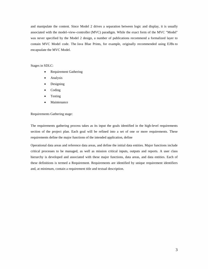
and manipulate the content. Since Model 2 drives a separation between logic and display, it is usually
associated with the model–view–controller (MVC) paradigm. While the exact form of the MVC "Model"
was never specified by the Model 2 design, a number of publications recommend a formalized layer to
contain MVC Model code. The Java Blue Prints, for example, originally recommended using EJBs to
encapsulate the MVC Model.
Stages in SDLC:
• Requirement Gathering
• Analysis
• Designing
• Coding
• Testing
• Maintenance
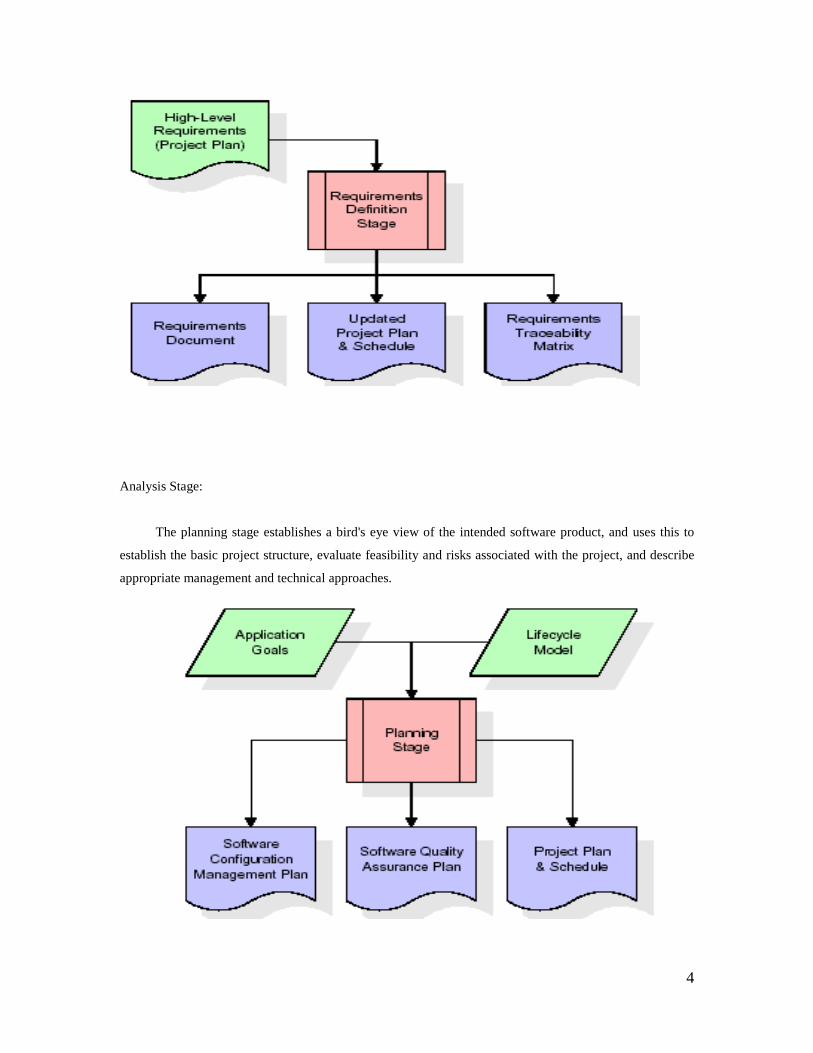
Requirements Gathering stage:
The requirements gathering process takes as its input the goals identified in the high-level requirements
section of the project plan. Each goal will be refined into a set of one or more requirements. These
requirements define the major functions of the intended application, define
Operational data areas and reference data areas, and define the initial data entities. Major functions include
critical processes to be managed, as well as mission critical inputs, outputs and reports. A user class
hierarchy is developed and associated with these major functions, data areas, and data entities. Each of
these definitions is termed a Requirement. Requirements are identified by unique requirement identifiers
and, at minimum, contain a requirement title and textual description.
4
Analysis Stage:
The planning stage establishes a bird's eye view of the intended software product, and uses this to
establish the basic project structure, evaluate feasibility and risks associated with the project, and describe
appropriate management and technical approaches.
5
The most critical section of the project plan is a listing of high-level product requirements,
also referred to as goals. All of the software product requirements to be developed during the requirements
definition stage flow from one or more of these goals. The minimum information for each goal consists of a
title and textual description, although additional information and references to external documents may be
included. The outputs of the project planning stage are the configuration management plan, the quality
assurance plan, and the project plan and schedule, with a detailed listing of scheduled activities for the
upcoming Requirements stage, and high level estimates of effort for the out stages
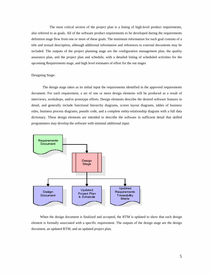
Designing Stage:
The design stage takes as its initial input the requirements identified in the approved requirements
document. For each requirement, a set of one or more design elements will be produced as a result of
interviews, workshops, and/or prototype efforts. Design elements describe the desired software features in
detail, and generally include functional hierarchy diagrams, screen layout diagrams, tables of business
rules, business process diagrams, pseudo code, and a complete entity-relationship diagram with a full data
dictionary. These design elements are intended to describe the software in sufficient detail that skilled
programmers may develop the software with minimal additional input.
When the design document is finalized and accepted, the RTM is updated to show that each design
element is formally associated with a specific requirement. The outputs of the design stage are the design
document, an updated RTM, and an updated project plan.
6
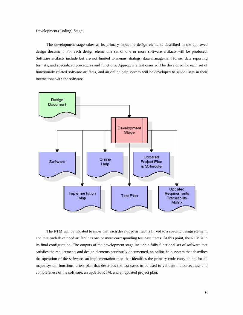
Development (Coding) Stage:
The development stage takes as its primary input the design elements described in the approved
design document. For each design element, a set of one or more software artifacts will be produced.
Software artifacts include but are not limited to menus, dialogs, data management forms, data reporting
formats, and specialized procedures and functions. Appropriate test cases will be developed for each set of
functionally related software artifacts, and an online help system will be developed to guide users in their
interactions with the software.
The RTM will be updated to show that each developed artifact is linked to a specific design element,
and that each developed artifact has one or more corresponding test case items. At this point, the RTM is in
its final configuration. The outputs of the development stage include a fully functional set of software that
satisfies the requirements and design elements previously documented, an online help system that describes
the operation of the software, an implementation map that identifies the primary code entry points for all
major system functions, a test plan that describes the test cases to be used to validate the correctness and
completeness of the software, an updated RTM, and an updated project plan.
7
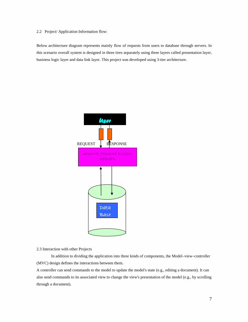
2.2 Project/ Application Information flow:
Below architecture diagram represents mainly flow of requests from users to database through servers. In
this scenario overall system is designed in three tires separately using three layers called presentation layer,
business logic layer and data link layer. This project was developed using 3-tier architecture.
REQUEST RESPONSE
2.3 Interaction with other Projects
In addition to dividing the application into three kinds of components, the Model–view–controller
(MVC) design defines the interactions between them.
A controller can send commands to the model to update the model's state (e.g., editing a document). It can
also send commands to its associated view to change the view's presentation of the model (e.g., by scrolling
through a document).
APACHE_TOMCAT 8.0.27.0 SERVER
User
Data Base
8
A model notifies its associated views and controllers when there has been a change in its state.
This notification allows the views to produce updated output, and the controllers to change the available set
of commands. A passive implementation of MVC omits these notifications, because the application does
not require them or the software platform does not support them.
2.4 Interactions with other Applications
We have took this project from a online enquiry system. We mainly took the references from
various tourism companies which offer various types for destinations with all three types of transportation.
2.5 Capabilities
The architecture of this project includes several individual modules. While developing the project
each module has developed individually. The following figure shows the process flow of all the modules
involved in the project.
2.6 Risk Assessment and Management
Before Risk assessment starts it is basic that an establishment is built up for giving organized venture data,
therefore, the accompanying task components were finished and characterized preceding building up this
Risk Management Plan:
Define the schedule, resources and cost for the project.
Develop a blue print for the Project
Develop master schedule and detailed schedules
Estimate the budget for the project
Identify required and available resources
Define Risk Management Roles and Responsibilities
Establish performance measurement metrics
Risk management should be handled.
Project group takes part in risk assessment gatherings and individuals serve as meeting recorder and
timekeeper Key partners partake in danger evaluation gatherings Project Sponsor may take part in danger
appraisal gatherings.
3 Project Requirements
3.1. Identification of Requirements:
Designing is the most important phase. The design process involves developing a conceptual view
of the system, establishing system structure, identifying data streams and data stores, decomposing high
level functions into sub-functions, establishing relationships , interconnection among components and
developing concrete data representations.
9
In the context of software, design is problem solving process whose objective is to Find and
describe the way to implement the functional requirements while respecting the constraints imposed by the
non functional requirements and by adhering to general principles of good quality.
The goal of the design process is to produce a model or representation of the system which can be
used later to build that system and use this model to build the overall system. The design process translates
requirements into a representation of the software that can be assessed for quality before coding begins.
3.2. Performance Requirements
The design process, the quality of the evolving design is assessed with a series of formal technical
reviews or design walkthroughs discussed is suggests three characteristics that serve as a guide for the
evaluation of a good design.
• The design must implement all of the explicit requirements contained in the analysis model and it
must accommodate all of the implicit requirements desired by the customer.
• The design must be a readable, understandable guide for those who generate code and for those
who test and subsequently support the software.
• The design should provide a complete picture of the software, addressing the data, functional and
behavioral domains from an implementation perspective. Each of these characteristics is actually a
goal of the design process. But how is each of these goals achieved. In order to evaluate the
quality of a design representation, must establish technical criteria for good design.
3.3. Security and Fraud Prevention
Object-oriented analysis and design (OOAD) is a software engineering approach that models a system
as a group of interacting objects. Each object represents some entity of interest in the system being
modeled, and is characterized by its class, its state (data elements), and its behavior. Various models can be
created to show the static structure, dynamic behavior, and run-time deployment of these collaborating
objects. There are a number of different notations for representing these models, such as the Unified
Modeling Language (UML).
Object-oriented analysis (OOA) applies object-modeling techniques to analyze the functional requirements
for a system. Object-oriented design (OOD) elaborates the analysis models to produce implementation
specifications. OOA focuses on what the system does, OOD on how the system does it.
Object-oriented system is an composed of objects. The behavior of the system results from the
collaboration of those objects. Collaboration between objects involves those sending messages to each
other. Sending a message differs from calling a function in that when a target object receives a message, it
itself decides what function to carry out to service that message. The same message may be implemented
by many different functions, the one selected depending on the state of the target object.
10
The implementation of "message sending" varies depending on the architecture of the system
being modeled, and the location of the objects being communicated with.
3.4. Software and Hardware Requirements
An object-oriented system is composed of objects. The behavior of the system is achieved through
collaboration between these objects, and the state of the system is the combined state of all the objects in it.
Collaboration between objects involves those sending messages to each other. The exact semantics of
message sending between objects varies depending on what kind of system is being modeled. In some
systems, "sending a message" is the same as "invoking a method". In other systems, "sending a message"
might involve sending data via a socket.
3.5. HTML and JavaScript
Object-oriented analysis (OOA) looks at the problem domain, with the aim of producing a
conceptual model of the information that exists in the area being analyzed. Analysis models do not consider
any implementation constraints that might exist, such as concurrency, distribution, persistence, or how the
system is to be built. Implementation constraints are dealt with during object-oriented design (OOD).
Analysis is done before the Design.
The sources for the analysis can be a written requirements statement, a formal vision document,
and interviews with stakeholders or other interested parties. A system may be divided into multiple
domains, representing different business, technological, or other areas of interest, each of which are
analyzed separately.
The result of object-oriented analysis is a description of what the system is functionally required to
do, in the form of a conceptual model. That will typically be presented as a set of use cases, one or more
UML class diagrams, and a number of interaction diagrams. It may also include some kind of user interface
mock-up.
4. Project Design Description
Tours and travels were developed to make it easy for the people to search for the trains and bus
details. This travels consists of mostly all southern cities trains and buses information. We are even
providing the particular details of the trains where we can see the details and if we can register the
particular details, same as to all such as for bus details, hotels. We even look for particular way of
reservation. we may come across many problems such as improper accommodation ,loose of money during
transaction ,transportation.
11
Project type:
Web Based Application.
Proposed system features The ‘INTRANET’ is an Enterprise Application that automates and improves
procedures within organizations. It is a useful technology for delineating the steps that must be taken, the
dependencies that must be enforced, and the approvals that must be obtained during the completion of
projects.
It is providing very easy way for the travelers for choosing the different places, hotels and many
more. it is easy to see the details for the user from the webpage. We may come across many problems such
as improper accommodations, loose of money during trasaction.we are providing the packages with less of
cost for the travelers. We provide all safety rules for the costumers who are going to visit our travel agency.
We provide safety, comfortable journey, and fast reservation with out any delay
We are providing the facilities such as while booking such as (trains, buses, hotels) they can book through
there credit or debit cards so that their will be no loose of money they will be safe of there money at any
time. The majority of travel requires discretionary income.discreationary income is money left over after all
monetary obligations (food rent and taxes) have been paid.
Administration processes are simplified allowing more time for management of resources. If the user is
admin he can upload notifications such as
Such as the user can search the particular details of the travel and they can login to the web page.
They can se the detail in the webpage such as train details, bus details, hotel details, etc.
• User can login with his id and password.
• They can view the details and they can register in to the details and they can search for
more information from the webpage.
• they can view the pictures of the places and hotels which are need.
• If they have any problem they can contact the tour manager where the contact details are
given in the homepage
5. Project Internal/external Interface Impacts and specification
System Requirement Specification
Software Requirements Specification plays an important role in creating quality software
solutions. Specification is basically a representation process. Requirements are represented in a manner that
ultimately leads to successful software implementation. Requirements may be specified in a variety of
ways. However there are some guidelines worth following:
• Representation format and content should be relevant to the problem
• Information contained within the specification should be nested
• Diagrams and other notational forms should be restricted in number and consistent in use.
• Representations should be revisable.
12
Hardware Requirements : PROCESSOR: PENTIUM
SPEED: 233 MHZ
MONITOR: SAMTRON
HARD DISK: 4.2 MB
RAM: 128 MB
MOUSE
KEYBOARD
Software Requirements:
The software requirements specification is produced at the culmination of the analysis task. The function
and performance allocated to the software as a part of system engineering are refined by establishing a
complete information description, a detailed functional and behavioral description, and indication of
performance requirements and design constraints, appropriate validation criteria and other data pertinent to
requirements.
An outline of the Software Requirements Specification:
A simplified outline can be given for the framework of the specifications. This is according to the
IEEE Standards.
OPERATING PLATFORM: WINDOWS 98/2000NTR OR ABOVE
DBMS: ORACLE 10G EXPRES EDITION
SOFTWARE: JDK 1.3.1_03,
WEBSERVER: APACHE_TOMCAT 8.0.27.0
BROWSER: INTERNET EXPLORER
FRONT END TOOL: HTML
DOCUMENTATION TOOL: MS – WORD 2000
6. Project Design Units Impact:
6.1 Functional Area/Design Unit
UML
The Unified Modeling Language (UML) is a standardized specification language for object
modeling. UML is a general-purpose modeling language that includes a graphical notation used to create an
abstract model of a system, referred to as a UML model.
Definition UML is a general purpose visual modeling language that is used to
1. specify
2. visualize
13
3. construct
4. document
The artifacts of the software system:
UML is a language It will provide vocabulary and rules for communications and function on conceptual
and physical representation. So it is a modeling language.
UML specifying Specifying means building models which are precise, unambiguous and complete. In
particular, the UML address the specification of all the important analysis, design and implementation
decisions that must be made in developing and displaying a software intensive system.
UML visualization The UML includes both graphical and textual representation. It makes easy to visualize
the system and for better understanding.
UML constructing UML models can be directly connected to a variety of programming languages and it is
sufficiently expressive and free from any ambiguity to permit the direct execution of models.
UML documenting UML provides variety of documents in addition to raw executable codes.
The system is designed using on UML. The UML modeling and design is a new way of thinking
about problems using models organized around real world concepts. UML is a standard language for
specifying, visualizing, constructing, and documenting the artifacts of software system, as well as for
business modeling and other non-software systems.
The UML is a very important part of developing objects oriented software and the software
development process. The UML uses mostly graphical notations to express the design of software projects.
Using the UML helps project teams communicate, explore potential designs, and validate the architectural
design of the software.
Reasons to model
• To communicate the desired structure and behavior of the system
• To visualize and control the system’s architecture.
• To better understand the system and expose opportunities for specification and reuse
• To manage risk
Uses of uml:
The UML is intended primarily for software intensive systems. It has been used effectively for
such domain as Enterprise information system, banking and financial services, telecommunications,
transportation, defense/aerospace, retails, medical, electronics, scientific fields, distributed wed

14
UML is the industry standard "language" for describing, visualizing, and documenting object-
oriented systems. UML is a collection of a variety of diagrams for differing purposes. Each type of diagram
models a particular aspect of object-oriented design in an easy to understand, visual manner.
The UML standard specifies exactly how the diagrams are to be drawn and what each component
in the diagram means. UML is not dependent on any particular programming language, instead it focuses
one the fundamental concepts and ideas that model a system. Using UML enables anyone familiar with
its specifications to instantly read and understand diagrams drawn by other people. There are UML
diagram for modeling static class relationships, dynamic temporal interactions between objects, the usages
of objects, the particulars of an implementation, and the state transitions of systems.
UML diagram consists of the following features
• Entities: These may be classes, objects, users or systems behaviors.
• Relationship: Lines that model the relationships between entities in the system.
• Generalization: A solid line with an arrow that points to a higher abstraction of the present item.
• Association: A solid line that represents that one entity uses another entity as part of its behavior.
• Dependency: A dotted line with an arrowhead that shows one entity depends on the behavior of
another entity.
Types of UML Diagrams UML defines nine types of Diagrams in which they are divided into two
categories. They are Static diagrams and Dynamic diagrams.
1. Class diagram
2. Object diagram
3. Use case diagram
4. Sequence diagram
5. Collaboration diagram
6. State chart diagram
7. Activity diagram
8. Component diagram
9. Deployment diagram
15
1. Class Diagram:
A Class Diagram shows a set of Classes, interfaces, Collaborations and their relationships. Class
Diagram models class structure and contents using design elements such as classes, packages and objects. It
also displays relationships such as containment, inheritance, associations and others.
2. Object Diagram:
An Object Diagram shows a set of Objects and their relationships.
3. Use case diagram:
A use case diagram shows the relationship among actors and use cases within a system. Use case
diagrams show elements from the use case model. The use case model represents functionality of a system
or a class as manifested to external actors with the system.
A use case diagram is a graph of actors, a set of use cases enclosed by a system boundary,
communication (participation) associations between the actors and the use cases, and generalizations
among the use cases.
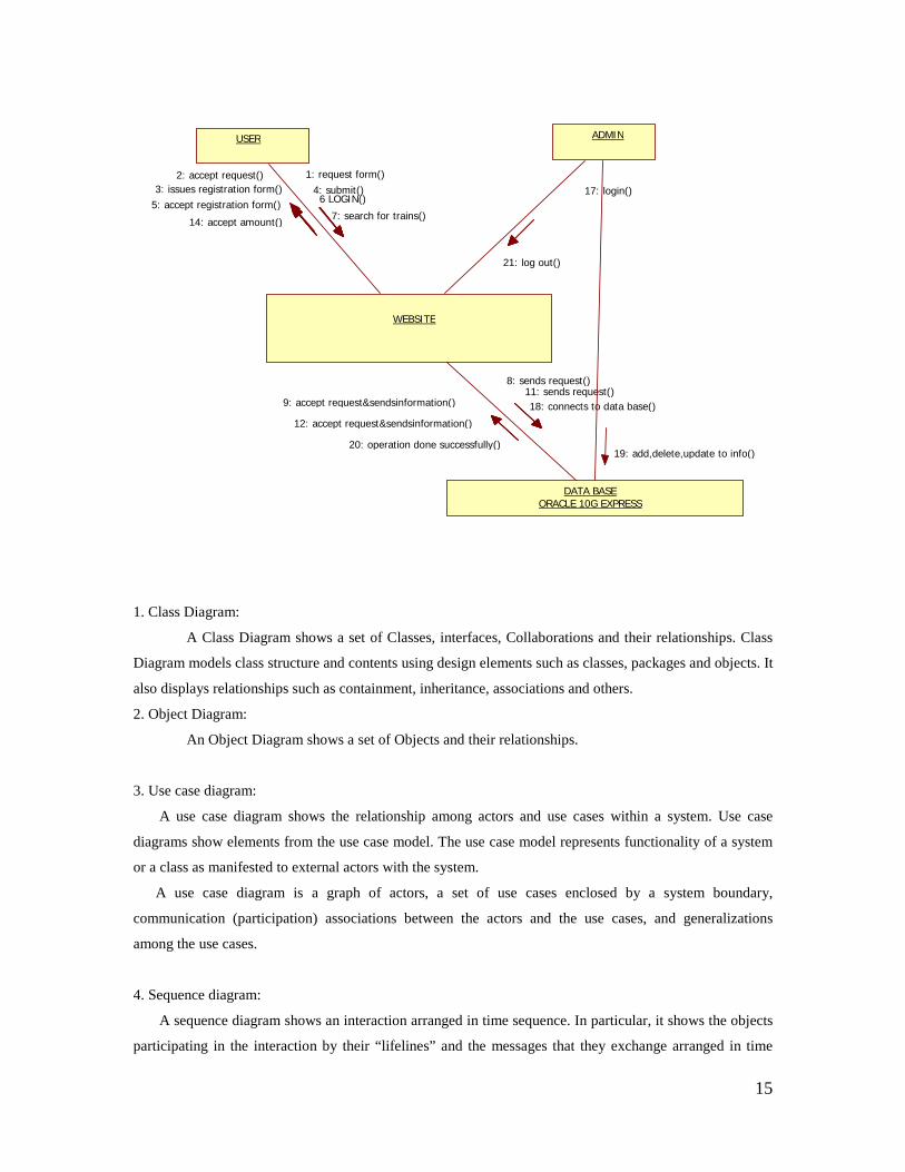
4. Sequence diagram:
A sequence diagram shows an interaction arranged in time sequence. In particular, it shows the objects
participating in the interaction by their “lifelines” and the messages that they exchange arranged in time
USER ADMIN
WEBSITE
DATA BASE ORACLE 10G EXPRESS
1: request form() 2: accept request() 3: issues registration form() 4: submit()
5: accept registration form() 6 LOGIN() 7: search for trains() 14: accept amount()
17: login()
21: log out()
9: accept request&sendsinformation() 12: accept request&sendsinformation()
20: operation done successfully()
8: sends request() 11: sends request() 18: connects to data base()
19: add,delete,update to info()
16
sequence. It does not show the associations among the objects. A sequence diagram represents an
Interaction, which is a set of messages exchanged among objects within collaboration to effect a desired
operation or result.
5. Collaboration Diagram:
A Collaboration Diagram is an interaction Diagram that emphasizes the structural organization of the
objects that send and receive messages. It shows a set of objects, links among those objects and messages
sent & received by those objects.
6. State Chart Diagram:
A State Chart Diagram shows a state machine, consisting of states, transitions, events and activities. State
Diagram emphasizes the event-ordered behavior of objects which is especially useful in modeling reactive
systems.
7. Activity diagram:
An Activity diagram is a dynamic diagram that shows the activity and the event that causes the object
to be in the particular state.
Activity diagrams show the flow of activities through the system. Diagrams are read from top to
bottom and have branches and forks to describe conditions and parallel activities. A fork is used when
multiple activities are occurring at the same time. The branch describes what activities will take place based
on a set of conditions. All branches at some point are followed by a merge to indicate the end of the
conditional behavior started by that branch. After the merge all of the parallel activities must be combined
by a join before transitioning into the final activity state.
8. Component Diagram:
A Component Diagram shows a set of Components and their relationships. Component diagram
are related to class diagram.
9. Deployment Diagram:
A Deployment diagram shows a set of nodes and their relationship. Deployment diagram are
related to component diagram.
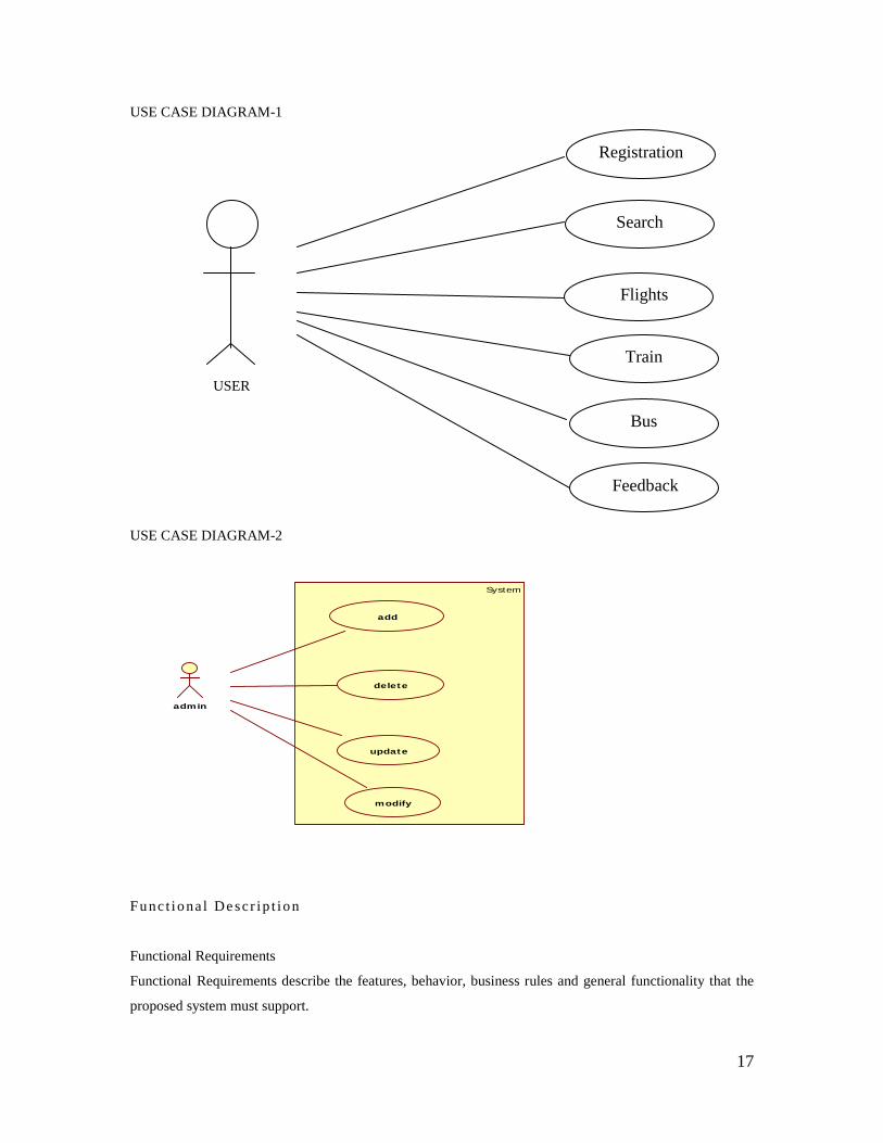
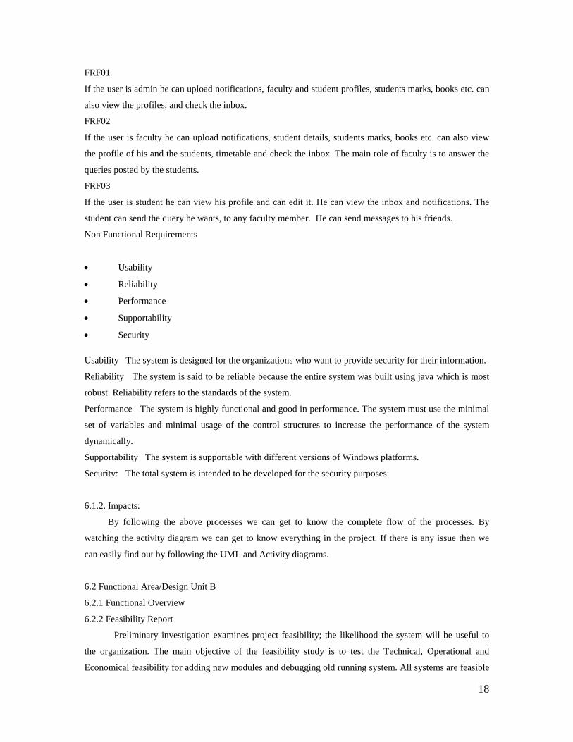
6.1.1 Functional Overview
USE CASE DOCUMENTATION
17
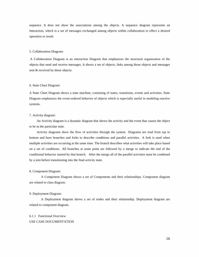
USE CASE DIAGRAM-1
USER
USE CASE DIAGRAM-2
System
admin
add
delete
update
modify
Fu nc t io na l De sc r ip t io n
Functional Requirements
Functional Requirements describe the features, behavior, business rules and general functionality that the
proposed system must support.
Train
Flights
Search
Registration
Bus
Feedback
18
FRF01
If the user is admin he can upload notifications, faculty and student profiles, students marks, books etc. can
also view the profiles, and check the inbox.
FRF02
If the user is faculty he can upload notifications, student details, students marks, books etc. can also view
the profile of his and the students, timetable and check the inbox. The main role of faculty is to answer the
queries posted by the students.
FRF03
If the user is student he can view his profile and can edit it. He can view the inbox and notifications. The
student can send the query he wants, to any faculty member. He can send messages to his friends.
Non Functional Requirements
• Usability
• Reliability
• Performance
• Supportability
• Security
Usability The system is designed for the organizations who want to provide security for their information.
Reliability The system is said to be reliable because the entire system was built using java which is most
robust. Reliability refers to the standards of the system.
Performance The system is highly functional and good in performance. The system must use the minimal
set of variables and minimal usage of the control structures to increase the performance of the system
dynamically.
Supportability The system is supportable with different versions of Windows platforms.
Security: The total system is intended to be developed for the security purposes.
6.1.2. Impacts:
By following the above processes we can get to know the complete flow of the processes. By
watching the activity diagram we can get to know everything in the project. If there is any issue then we
can easily find out by following the UML and Activity diagrams.
6.2 Functional Area/Design Unit B
6.2.1 Functional Overview
6.2.2 Feasibility Report
Preliminary investigation examines project feasibility; the likelihood the system will be useful to
the organization. The main objective of the feasibility study is to test the Technical, Operational and
Economical feasibility for adding new modules and debugging old running system. All systems are feasible
19
if they are given unlimited resources and infinite time. There are aspects in the feasibility study portion of
the preliminary investigation:
• Technical Feasibility
• Operation Feasibility
• Economic Feasibility
Technical Feasibility
The technical issue usually raised during the feasibility stage of the investigation includes the following:
• Does the necessary technology exist to do what is suggested?
• Do the proposed equipment’s have the technical capacity to hold the data required to use the
new system?
• Will the proposed system provide adequate response to inquiries, regardless of the number or
location of users?
• Can the system be upgraded if developed?
Are there technical guarantees of accuracy, reliability, ease of access and data security?
Operational Feasibility
User-friendly
Customer will use the forms for their various transactions i.e. for adding new routes, viewing the
routes details. Also the Customer wants the reports to view the various transactions based on the
constraints. These forms and reports are generated as user-friendly to the Client.
Reliability
The package wills pick-up current transactions on line. Regarding the old transactions, User will enter
them in to the system.
Security
The web server and database server should be protected from hacking, virus etc.
Portability
The application will be developed using standard open source software (Except Oracle) like Java,
tomcat web server, Internet Explorer Browser etc. these software will work both on Windows and Linux
o/s. Hence portability problems will not arise.
Availability
This software will be available always.
Maintainability
The system called the ewheelz uses the 2-tier architecture. The 1st tier is the GUI, which is said to be
front-end and the 2nd tier is the database, which uses MYSQL, which is the back-end.
The front-end can be run on different systems (clients). The database will be running at the server.
Users access these forms by using the user-ids and the passwords.
Economic Feasibility
20
The computerized system takes care of the present existing system’s data flow and procedures completely
and should generate all the reports of the manual system besides a host of other management reports. It
should be built as a web based application with separate web server and database server. This is required as
the activities are spread throughout the organization customer wants a centralized database. Further some of
the linked transactions take place in different locations Open source software like TOMCAT, JAVA, Mysql
and Linux is used to minimize the cost for the Customer.
6.2.3 System Testing and Implementation:
In order to make sure that the system does not have errors, the different levels of testing strategies that are
applied at differing phases of software development are:
Unit Testing:
In this strategy some test cases are generated as input conditions that fully execute all functional
requirements for the program. This testing has been uses to find errors in the following categories:
Incorrect or missing functions
Interface errors
Errors in data structure or external database access
Performance errors
Initialization and termination errors.
In this testing only the output is checked for correctness. The logical flow of the data is not checked.
White Box testing:
In this the test cases are generated on the logic of each module by drawing flow graphs of that
module and logical decisions are tested on all the cases. It has been uses to generate the test cases in the
following cases:
Guarantee that all independent paths have been executed.
Execute all logical decisions on their true and false Sides.
Execute all loops at their boundaries and within their operational bounds
Integrating Testing:
Integration testing ensures that software and subsystems work together a whole. It tests the
interface of all the modules to make sure that the modules behave properly when integrated together.
System Testing:
Involve in-house testing of the entire system before delivery to the user. Its aim is to satisfy the
user the system meets all requirements of the client's specifications.
Acceptance Testing:
It is a pre-delivery testing in which entire system is tested at client's site on real world data to
find errors.

21
Test Approach:
Testing can be done in two ways:
Bottom up approach
Top down approach
Bottom up Approach:
Testing can be performed starting from smallest and lowest level modules and proceeding one at a
time. For each module in bottom up testing a short program executes the module and provides the needed
data so that the module is asked to perform the way it will when embedded within the larger system. When
bottom level modules are tested attention turns to those on the next level that use the lower level ones they
are tested individually and then linked with the previously examined lower level modules.
Top down approach:
This type of testing starts from upper level modules. Since the detailed activities usually
performed in the lower level routines are not provided stubs are written. A stub is a module shell called by
upper level module and that when reached properly will return a message to the calling module indicating
that proper interaction occurred. No attempt is made to verify the correctness of the lower level module.
6.3 OUTPUT SCREENS:
HOME SCREEN:
22
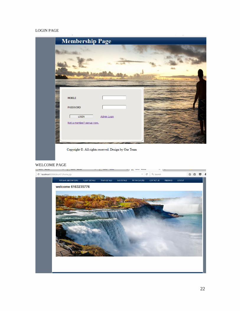
LOGIN PAGE
WELCOME PAGE
23
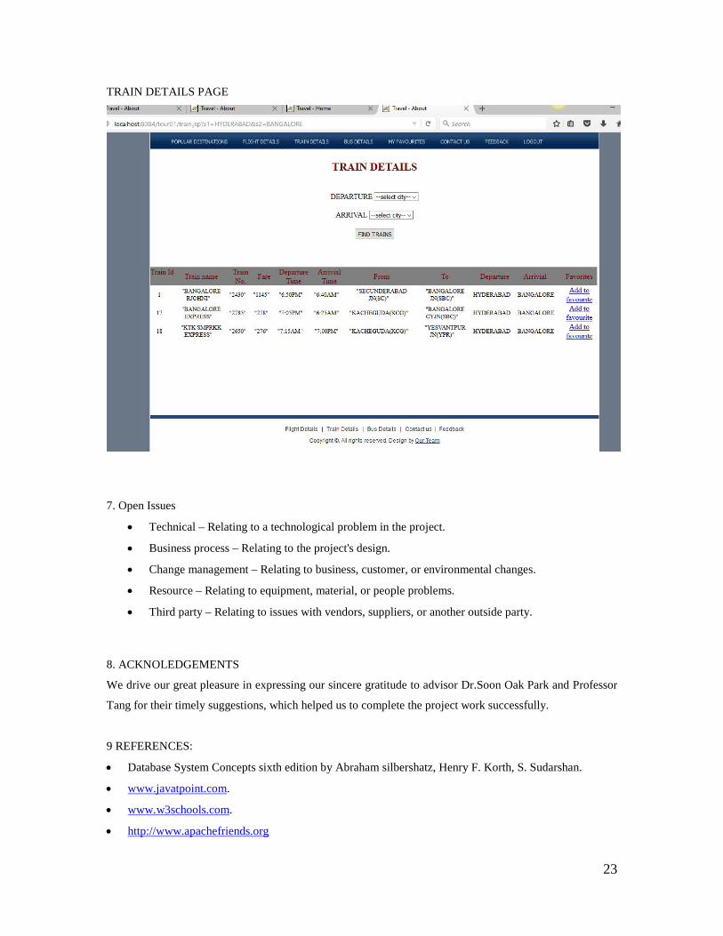
TRAIN DETAILS PAGE
7. Open Issues
• Technical – Relating to a technological problem in the project.
• Business process – Relating to the project's design.
• Change management – Relating to business, customer, or environmental changes.
• Resource – Relating to equipment, material, or people problems.
• Third party – Relating to issues with vendors, suppliers, or another outside party.
8. ACKNOLEDGEMENTS
We drive our great pleasure in expressing our sincere gratitude to advisor Dr.Soon Oak Park and Professor
Tang for their timely suggestions, which helped us to complete the project work successfully.
9 REFERENCES:
• Database System Concepts sixth edition by Abraham silbershatz, Henry F. Korth, S. Sudarshan.
• www.javatpoint.com.
• www.w3schools.com.
• http://www.apachefriends.org