Embed Size (px)
Citation preview

Author: Frank Ewert Siemens AG Energy Sector Service Division
Online Monitoring - Early detection and diagnosis of initiating damages in turbo generators
Power Gen Europe 2014 June 3-5, 2014 Cologne, Germany
siemens.com/energy
AL: N; ECCN: N Unrestricted © Siemens AG 2014. All rights reserved. Page 2 of 20
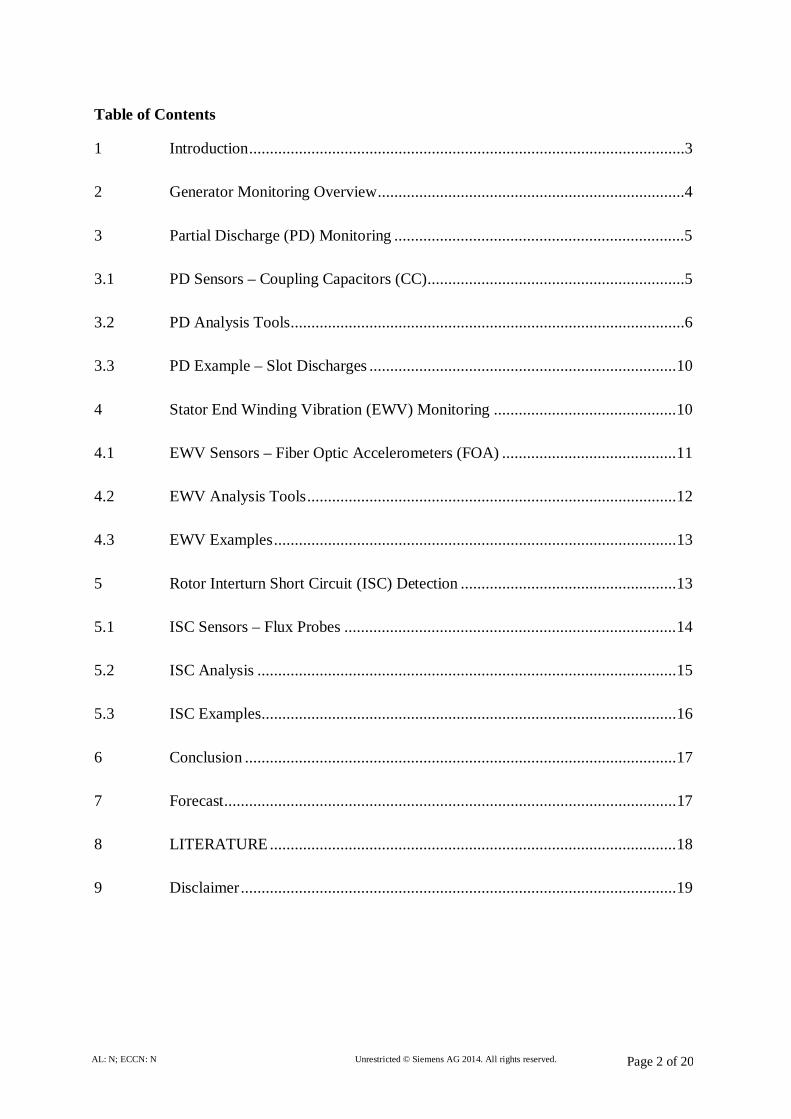
Table of Contents
1 Introduction .........................................................................................................3
2 Generator Monitoring Overview ..........................................................................4
3 Partial Discharge (PD) Monitoring ......................................................................5
3.1 PD Sensors – Coupling Capacitors (CC) ..............................................................5
3.2 PD Analysis Tools ...............................................................................................6
3.3 PD Example – Slot Discharges .......................................................................... 10
4 Stator End Winding Vibration (EWV) Monitoring ............................................ 10
4.1 EWV Sensors – Fiber Optic Accelerometers (FOA) .......................................... 11
4.2 EWV Analysis Tools ......................................................................................... 12
4.3 EWV Examples ................................................................................................. 13
5 Rotor Interturn Short Circuit (ISC) Detection .................................................... 13
5.1 ISC Sensors – Flux Probes ................................................................................ 14
5.2 ISC Analysis ..................................................................................................... 15
5.3 ISC Examples .................................................................................................... 16
6 Conclusion ........................................................................................................ 17
7 Forecast ............................................................................................................. 17
8 LITERATURE .................................................................................................. 18
9 Disclaimer ......................................................................................................... 19

AL: N; ECCN: N Unrestricted © Siemens AG 2014. All rights reserved. Page 3 of 20
1 Introduction The influence of renewable energy – especially wind energy – is increasing. This trend results
in an increased requirement of medium and peak load operation of fossil power for the
stabilization of the electrical grid. Especially for large fossil power plants this medium and
peak load operation results in an increased thermo-mechanical stress for the core components
like the generator due to the increasing number of load cycles. This typically results in an
accelerated aging of the machines and the risk for damages and unexpected failures. As a
preventive measure inspections in more frequent intervals offer insight into the condition of
the generator, but they cost expensive outage time of the power plant. To minimize loss of
revenue, it is helpful to use online condition monitoring and diagnosis systems to receive
information about the state of the machine during operation. This will lead to condition based
maintenance with extended operating periods in between stand stills.
a) Online monitoring of partial discharges enables the user to detect an abnormal
condition in the electrical insulation system of the generator.
b) Online monitoring of stator end winding vibrations yields information about the actual
vibrations during operation, e.g. depending on the specific load point.
c) Online monitoring of the air gap magnetic flux helps to identify interturn short circuits
within the rotor windings.
Only the interaction of the above mentioned online monitoring systems in correlation with the
operational parameters enables a powerful generator diagnostic.

AL: N; ECCN: N Unrestricted © Siemens AG 2014. All rights reserved. Page 4 of 20
2 Generator Monitoring Overview
Generators are in service in power plants for many years. Operation
and ageing can gradually cause damage to its high-voltage insulation.
If early detection of changes in the components is possible through in-
process long-term diagnosis, unscheduled and expensive outages can
be prevented and measures can be scheduled and taken to extend the
service life of generators. Monitoring systems for different parameters
are available, but at Siemens the focus is on the monitoring of partial
discharges (PD), end winding vibrationss (EWV) and interturn short
circuit (ISC). Other systems for shaft voltage/current and fiber optic stator and rotor
temperature monitoring are available or in development but not mentioned here.
The typical Siemens generator monitoring concept of the main monitoring systems mentioned
above is illustrated in Figure 1.
Figure 1: Overview of SIEMONplus monitoring system
Monitoring usually starts with the sensors which are installed inside the generator (vibration
and flux) or in the direct vicinity of the generator, for example, inside the iso-phase bus

AL: N; ECCN: N Unrestricted © Siemens AG 2014. All rights reserved. Page 5 of 20
(partial discharge). The signals of the sensors are routed to a data acquisition unit (AU),
located in the turbine hall. All relevant data is stored on the AU and can be downloaded for
diagnosis. By extending the system by a central server, up to 20 generators can be monitored
and the data can be stored, visualized and compared to each other. The server can be easily
connected to any I&C systems like plant information (PI) system and T3000 system or to a
superordinated Siemens system like the WIN_TS system. Once connected to one of these
systems the data can be automatically transferred to one of the Siemens Power Diagnostic
Centers, where the data is observed permanently by high sophisticated rule based analyses
which includes the automatic comparison of the measured data with all relevant and existing
generator parameters. In case of any deviations from the normal behavior the Siemens experts
are informed to perform a detailed evaluation of the data and to provide recommendations for
the customer.
3 Partial Discharge (PD) Monitoring
Electrical faults in high voltage components like a turbine generator do not occur suddenly. In
nearly all cases however, defects get announced by PDs bridging part of the high voltage
insulation and are detectable with RF-measurement methods [1].
The distribution of the discharges with respect to the phase angle of the generator voltage is
characteristic for the cause of discharges and allows for conclusions to the grade of risk for
the further operating of the high voltage equipment.
The PD measuring system can be normalized according to IEC/TS 60034-27-2. By
transformation of the measured voltage signals to charge units, being a measure for the
transferred electrical energy, an estimation of the risk is possible. Although the generator, as
the most expensive electrical component, is generally the main target of supervision, the
complete high voltage area including the main and auxiliary transformers is being monitored
by registration of PD signals.
3.1 PD Sensors – Coupling Capacitors (CC)
For the detection of PDs, special coupling capacitors have to be installed in existing voltage
transformer cabinets (Figure 2a), generator terminal boxes (Figure 2b), inside the isolated

AL: N; ECCN: N Unrestricted © Siemens AG 2014. All rights reserved. Page 6 of 20
phase bus (IPB) (Figure 2c), inside generator neutral cabinets (Figure 2d) or at other suited
places in the high voltage area of the power plant [5].
The coupling capacitors are used to pick up the PD signals from the high voltage line. The
capacitors usually have a capacity in the range of 1nC to 9nC. Coupling capacitors with lower
capacities are not used due to a decreased sensitivity which not fulfills the Siemens
requirements. Usually the capacitors are equipped with an integrated over voltage protection
and have an insulated signal output to avoid any eddy currents along the cable shields.
Possible locations for the installation are shown in Figure 2:
a) CC inside voltage transformer cabinet b) CC inside generator terminal box
c) CC inside IPB d) CC inside generator neutral cabinet
Figure 2: Location of different measuring points within HV area of large power plants
3.2 PD Analysis Tools
Phase Resolved Partial Discharge (PRPD) Pattern
The most known and powerful tool is the analysis of the PRPD patterns (Figure 3).
Figure 3: Examples of PRPD Patterns

AL: N; ECCN: N Unrestricted © Siemens AG 2014. All rights reserved. Page 7 of 20
These patterns typically show the PD distribution map of PD magnitude vs. AC cycle phase
position, for visualization of the PD behavior during a predefined measuring time. A
classification and interpretation of these patterns can be done by using the international
pattern catalog (IEC/TS 60034-27-2).
Trending over the lifetime
Usually the monitoring of a generator starts with the fingerprint measurement, which is the
first measurement after the monitoring system was commissioned and the generator at base
load. The fingerprint measurement is used as a reference for any future analyses. The
measurement further serves to identify narrow-band interference and to eliminate these with
digital interference suppression in order to improve the measurement sensitivity.
Figure 4: Example of PD trends
Once the fingerprint measurement is done, the trending (Figure 4) of the following common
PD parameters starts:
• QIEC [nC] Apparent charge according IEC60270
• Qmax [nC] Maximum Charge
• N [1/s] PD rate
• QR [nC²/s] Quadratic charge rate
According to IEC 60027-2 [2], the above mentioned common PD parameters should be
correlated with the following generator parameters:
• Slot temperatures
• Cold and warm gas temperatures
• Stator currents of all three phases

AL: N; ECCN: N Unrestricted © Siemens AG 2014. All rights reserved. Page 8 of 20
• Stator voltages of all three phases
• Active and reactive power
• Exciter current
Oscillograms
As a basis for Time of Flight (ToF) measurement for localization it becomes important to
evaluate high resolved oscillograms (Figure 5) taken with a sampling frequency of up
125MS/s 4 channels simultaneously over one AC cycle of the high voltage (50Hz 20ms).
Figure 5: Example of an oscillogram
Furthermore the oscillogramms can be used to determine the slew rates of the PD impulses to
get information about the source or the origin of any PD impulses. For example, the slew rate
of PD impulses coming from inside the insulation system, which travel through the generator
winding are damped much more than impulses coming from outside the generator, e.g.
impulses of an IPB supporter with a poor contact to the lead.
Time of flight (ToF) measurements for PD localization
Most of the PD monitoring systems on the market provide the possibility of performing ToF
measurements for fault localization (Figure 6).
Figure 6: Example of a ToF measurement
t = 250ns
tr = 20ns

AL: N; ECCN: N Unrestricted © Siemens AG 2014. All rights reserved. Page 9 of 20
Based on a high bandwidth and high sample rates the signal behavior of PD pulses can be
analyzed as function of place [3]. The signal shape of the PD pulse and the comparison for
both test points give some knowledge about the discharge source.
The difference of the propagation times of the measured pulses can be determined and the
possible region of the corresponding PD activity can be restricted. By this way in first order
the travel direction of the pulses can be directly calculated.
If there are well defined signal propagation paths between two test points (e.g. along the IPB),
the analysis of the travel time allows the calculation of the distance of the PC source with
respect to both test points. For time differences below the calibrated travel time between both
test points, the place of the PD source is located between both test points and can be
determined with an accuracy depending on the steepness of the pulses and the geometry of the
propagation paths.
Suppression of Interferences
In general PD measured in power plants is superimposed by a lot of noise signals, which have
to be eliminated prior to any further processing. Those signals can be principally divided in
sinusoidal and pulse shaped signals.
Sinusoidal noise, e.g. transmission signals on the power lines, often fully mask any PD pulses
contained in the measured signal. Because each data set is high resolved in time domain, it
can be filtered digitally by transforming it to frequency domain, filtering the resulting signal
from the dominating resonance frequencies using digital notch filters and transforming it back
to time domain [5].
Typical pulse shaped signals are, for example, the six equidistant commutation impulses of
the static excitation system (6-pulses-bridge). These impulses are caused by switching of the
semiconductors in the static exciter power converter and they are typical for operation of
generators with static excitation system with slip rings (Figure 7).
Figure 7: Example of an unfiltered (on the left) and filtered signal (on the right)

AL: N; ECCN: N Unrestricted © Siemens AG 2014. All rights reserved. Page 10 of 20
These high frequency pulses couple from the generator rotor winding via air gap into the
stator winding and represent a normal phenomenon at all generators with static excitation.
They can be used as a sensitivity check for PD online monitoring systems, which operate in
wide band mode at low frequency range acc. IEC 60034-27-2.
Figure 7 shows the effect of filtering the typical six equidistant impulses of the static
excitation system.
3.3 PD Example – Slot Discharges
Slot discharges typically appear between the outer corona protection (OCP) and the stator
core. The typical appearance of slot discharges is an unsymmetrical distribution of the
discharges covering the amplitude and number within the two halve waves, which can be
clearly seen in the PRPD pattern presented in Figure 8.
Figure 8: Example of PD - slot discharges
In the negative halve wave higher PDs appear. In both halve waves the PDs appear between
the zero crossing and maximum/ minimum of the high voltage cycle. The PRPD patterns of
slot discharges typically show a triangular shape [4,5].
4 Stator End Winding Vibration (EWV) Monitoring
All forces that act periodically cause elastic structures to vibrate. Such forces occur in every
generator. Vibration represents a cyclic load for the affected components, and increased
vibration levels means an increased load, the load being proportional to the vibration
amplitude. High levels of vibration cause the end-winding assembly to loosen and can lead to
rubbing and fracture of the affected components [6].
The end-winding sections of generator are excited particularly by
1) the core which vibrates at twice the line frequency and

AL: N; ECCN: N Unrestricted © Siemens AG 2014. All rights reserved. Page 11 of 20
2) current forces and
3) bearing and shaft vibration.
The unusually high currents and torques associated with line short-circuits, lightning strikes
and out-of-phase synchronization have a particularly pronounced effect on the end windings
of generators. Although generators may not be damaged by such events, it cannot completely
ruled out that such events can cause a certain amount of damage to the stator winding. To
prevent any secondary damage, the affected generator must be inspected to identify and repair
potentially loose braces or ties particularly in the end-winding section.
The condition of generator end windings is typically examined visually. Loosening of end-
winding assemblies causes secondary damage and increases the cost and effort of any repair
measures. Omitted or late repair can mean that the generator has to be completely re-wound.
End-winding vibration monitoring thus is a useful tool for evaluating the condition of
generator end windings and also minimizes the risk of a re-wind.
4.1 EWV Sensors – Fiber Optic Accelerometers (FOA)
Online monitoring of end winding vibrations is performed by recording local accelerations
during regular operation. Special fiber optic accelerometers are placed on the bar end
connections of the stator end windings (see Figure 9) considering the results of an offline
modal analysis (bump test). These sensors are free of any metal parts and do not interfere with
the electromagnetic field in the end winding area. A minimum of six, but better even eight,
sensors per end winding should be used to allow a reliable data analysis.
Figure 9: Application of fiber optic accelerometers inside a stator end winding basket. The
fiber optic accelerometers are non-metallic and do not interfere with the electromagnetic field
in the end winding area.

AL: N; ECCN: N Unrestricted © Siemens AG 2014. All rights reserved. Page 12 of 20
4.2 EWV Analysis Tools
Real time signals are usually used to check the general functionality of the sensors. The
signals of the up to 16 fiber optic sensors are acquired with a sampling frequency of 9kS/s
simultaneously to enable the possibility to perform online modal analyses.
Figure 10: Screenshot of SIEMONplus EWV monitoring software
By using a fast fourier transformation (FFT), the time domain signals are transformed into the
frequency domain. Here usually the first and second harmonics of the line voltage are
observed and the respective amplitudes, which usually represent the vibration level in [µm],
are trended for every sensor signal separately. The trend of the vibration values can be
displayed and correlated to operational parameters, for example, active power, reactive power
and exciter current, which may have a direct influence to the end winding vibration
behaviour.
Advanced Analysis
Modern end winding vibration monitoring systems provide an online modal analysis of the
end winding vibration signals [7]. The Siemens system provides the online evaluation and
visualization of the standstill and rotating vibration modes separately. The respective changes
of these vibration modes during operation are trended, to be able to detect possible changes of
the structure mechanic behavior of the generator end winding. For such kind of diagnostics a
detailed knowledge of the generator design is necessary to define potential measures.

AL: N; ECCN: N Unrestricted © Siemens AG 2014. All rights reserved. Page 13 of 20
4.3 EWV Examples
Figure 11: Typical examples of EWV
In most cases end winding vibrations are indicated by friction dust caused by relative
movements of different end winding components (bandings, blocking elements, etc.). The
permanent mechanical stresses to single bars can lead to fatigue cracks of single strands. In
case of cracked single bars, the produced heat, caused by the cyclic interrupted current, leads
to a perforation and discoloration of the bar insulation.
5 Rotor Interturn Short Circuit (ISC) Detection
A major portion of rotor faults are related to some kind of winding faults, such as earth faults,
shorted windings, or cracked conductors [1]. Some of the winding faults do not directly lead
to a trip of the generator, but may lead to increased shaft vibrations, excessive wear or simply
reduced efficiency. Therefore a rotor winding monitor is a useful tool for fault analysis [8].
Different mechanisms can be responsible for shorted rotor turns. Most shorted turns are
caused by some kind of relative movement in the rotor turns. This relative movement may
lead to misalignment of the insulation layer between individual turns, failure of turn-to-turn
insulation, or loosening of blocking elements in the end winding region. Relative movement
of rotor winding parts is unavoidable due to the fact that the copper of the windings has a
thermal expansion coefficient different from that of the insulation materials and the rotor
body. During each start-up and shut-down the copper windings move relative to the rotor slots
and the insulating parts. An experienced and reliable rotor winding design takes care of this
thermo-mechanical mechanism. Otherwise relative movement leads to increased wear of the
insulating materials and ultimately to interturn short circuits. Sometimes even plastic

AL: N; ECCN: N Unrestricted © Siemens AG 2014. All rights reserved. Page 14 of 20
deformation can occur leading to end turn elongation, which in turn may cause the loosening
of blocking materials in the end winding region and ultimately to shorted turns.
The effects of such shorted turns depend on the number of shorted turns as well as their
location. In the first place, shorted turns require a higher field current than previously to run at
a specific load, thereby decreasing the efficiency. Higher field currents result in higher overall
field operating temperatures. In the case of a two-pole rotor, shorted turns in one pole lead to
increased temperatures on that side of the rotor only. This leads to thermal unbalance in the
rotor and increased vibrations due to thermal bowing. Four-pole rotors may suffer from
magnetic unbalance in case of shorted turns in one pole. Interturn short circuits or earth faults
in the end winding region may produce arcing underneath the retaining ring, leading to
retaining ring damage.
5.1 ISC Sensors – Flux Probes
For the detection of shorted turns, a sensor which measures the magnetic flux has to be
installed in the air gap between the rotor and the stator. The sensor is typically installed in the
3 o’clock or 9 o’clock position and is fastened on top of a stator slot wedge near the turbine
end of the generator (see Figure 12).
Figure 12: Installation of air gap sensor at stator winding slot wedge
The monitoring system analyses the magnetic flux continuously during the unit’s operation by
detecting changes in the rotor slot leakage flux signal provided by the sensor. It will detect
most of the shorted turns which can occur at a generator rotor and issue an alarm if a shorted
turn was detected. Also an identification of the affected slot of the rotor is possible.

AL: N; ECCN: N Unrestricted © Siemens AG 2014. All rights reserved. Page 15 of 20
5.2 ISC Analysis
The measured magnetic flux does not cross the air gap to reach the stator windings. Its
magnitude is proportional to the current flowing through the active turns in each slot. This
fact is used for the diagnostic of shorted turns (see Figure 13).
Figure 13: Magnetic flux distribution around a two-pole generator
The sensitivity to detect shorted turns in the coils depends on the load point. Therefore it is
necessary to use a very sensitive data acquisition system. To detect even smallest changes in
magnitude the Siemens system uses a sampling frequency of 100kHz and a resolution of 24
bit. By using such a high resolution it is not necessary anymore to approach different load
points between no-load and full-load (flux density zero crossing). By performing a pole-to-
pole comparison of the heights of the flux probe waveform peaks, the decrease in the number
of active turns in the affected pole can be detected.
Figure 14: Screenshot of SIEMONplus ISC monitoring software

AL: N; ECCN: N Unrestricted © Siemens AG 2014. All rights reserved. Page 16 of 20
By trending the data in case of an existing short, possible growing of rotor winding defects
can be detected in an early stage and the planning of the next maintenance outage can be
supported to minimize loss of revenue.
5.3 ISC Examples
Typical reasons for rotor interturn short circuits are for example end-turn distortions or copper
chloride contamination. End-turn distortions appear usually due to aging by relative
movements of the rotor turns. The resulting misalignment of the insulation layers causes
failures of the turn-to-turn insulation. Copper chloride contamination can lead to conductive
bridges between the turns (Figure 14).
Figure 14: Typical ISC examples

AL: N; ECCN: N Unrestricted © Siemens AG 2014. All rights reserved. Page 17 of 20
6 Conclusion
A successful diagnostic of the generator condition is dependent on the information which is
available. The more monitoring modules and operational parameters are available the more
successful is the diagnostic. As stated before one of the most important benefits of the
monitoring of the generator condition is the reduction of maintenance costs and unexpected
shut downs. Monitoring can help to optimize outages by early recommendations based on the
condition of the generator. This leads to minimized outage times due to the fact that all
necessary repair measures are planned in advance and all spare parts are available just in time.
Another goal of the generator monitoring is the extension of periods between maintenance
outages based on experienced analysis of operational conditions, machine characteristics,
maintenance history and online diagnostics. Last but not least a life time extension of
generator components, such as stator or rotor windings, bushings or circuit rings can be
achieved by assisting the maintenance and overhaul of these components.
7 Forecast
Currently the main focus of Siemens is to establish a modular generator diagnostic platform
by integrating other monitoring modules to the existing SIEMONplus system such as the
permanent fiber optic temperature and strain monitoring. Enabling this possibility, local hot
spots can be detected in an early stage during operation independent of any magnetic fields or
high voltages. Possible applications are:
Temperatures at cooling gas exit (direct hydrogen cooled generators)
Local hot spots at teeth of the core or cooling slots
Hot spots at front end connections, main leads or generator bushings
The permanent monitoring of these temperatures enables the possibility of trending the
temperature behavior in correlation to the operational parameters such as the generator load.
Critical overheating, which can leads to damages and unexpected outages can be avoided by
changing the load operation.
Further modules like the shaft voltage/current monitoring, which enables the possibility to
detect poor insulation of generator bearings and failures of grounding brushes are currently

AL: N; ECCN: N Unrestricted © Siemens AG 2014. All rights reserved. Page 18 of 20
under development and will be available next FY as additional modules for the generator
monitoring and diagnostic platform SIEMONplus.
8 LITERATURE
[1] P. Grünewald, R. Koziel, S. Piel, J. Weidner (1995): Erhöhte Kraftwerksverfügbarkeit
durch On-Line-Überwachung von Hochspannungsbetriebsmitteln mit HF-
Meßverfahren. 40. Int. Wiss. Koll. Ilmenau
[2] Ewert, F.; Biesemann, M. (2009): TE-Monitoring an Hochspannungsbetriebsmitteln in
Kraftwerken – Diagnose durch Korrelation mit Betriebsparametern und Fehlerortung
mittels Laufzeitmessung, ETG-Kongress, Düsseldorf, FT 4: Diagnostik elektrischer
Betriebsmittel, S. 307 – 312
[3] Piel, St.; Koziel, R.; Aumann, R.; Meißner, R. (2002): PD Identification and Fault
Localization in Power Plants by Remote Controlled Pulse Propagation Measurements,
CIGRE Conference, Paper 11-203, Paris, France
[4] Nattrass, D. A. (1988): Partial Discharge Measurement and Interpretation, IEEE
Electrical Insulation Magazine, Vol. 4, No. 3, pp10 – 23
[5] IEC/TS 60034-27-2: Rotating electrical Machines – Part 27-2: On-line partial discharge
measurements on the stator winding insulation of rotating electrical machines
[6] Thien, D.; Romanowski, H.; Strack, S.; Kempen, S.; Krol, Th.; Langmann, A. (2008):
Online and Offline Vibration Analysis of Stator End Windings of Large Power
Generators, Proc. of ASME Turbo Expo, Paper GT2008-51130, Berlin, Germany
[7] Thien, D.; Kreischer, C.; Kulig, S. (2011): Modal Analysis of Operational End Winding
Vibrations, IEEE International Electric Machines & Drives Conference (IEMDC)
[8] Wood, J.W.; Hindmarch, R.T.: Rotor winding short detection, IEE Proc. 133B(3), pp.
181-9

AL: N; ECCN: N Unrestricted © Siemens AG 2014. All rights reserved. Page 19 of 20
9 Disclaimer These documents contain forward-looking statements and information – that is, statements
related to future, not past, events. These statements may be identified either orally or in
writing by words as “expects”, “anticipates”, “intends”, “plans”, “believes”, “seeks”,
“estimates”, “will” or words of similar meaning. Such statements are based on our current
expectations and certain assumptions, and are, therefore, subject to certain risks and
uncertainties. A variety of factors, many of which are beyond Siemens’ control, affect its
operations, performance, business strategy and results and could cause the actual results,
performance or achievements of Siemens worldwide to be materially different from any
future results, performance or achievements that may be expressed or implied by such
forward-looking statements. For us, particular uncertainties arise, among others, from changes
in general economic and business conditions, changes in currency exchange rates and interest
rates, introduction of competing products or technologies by other companies, lack of
acceptance of new products or services by customers targeted by Siemens worldwide,
changes in business strategy and various other factors. More detailed information about
certain of these factors is contained in Siemens’ filings with the SEC, which are available on
the Siemens website, www.siemens.com and on the SEC’s website, www.sec.gov. Should one
or more of these risks or uncertainties materialize, or should underlying assumptions prove
incorrect, actual results may vary materially from those described in the relevant forward-
looking statement as anticipated, believed, estimated, expected, intended, planned or
projected. Siemens does not intend or assume any obligation to update or revise these
forward-looking statements in light of developments which differ from those anticipated.
Trademarks mentioned in these documents are the property of Siemens AG, its affiliates or
their respective owners.

AL: N; ECCN: N Unrestricted © Siemens AG 2014. All rights reserved. Page 20 of 20
Published by and copyright © 2014: Siemens AG Energy Sector Freyeslebenstrasse 1 91058 Erlangen, Germany
Siemens Energy, Inc. 4400 Alafaya Trail Orlando, FL 32826-2399, USA
For more information, please contact our Customer Support Center. Phone: +49 180/524 70 00 Fax: +49 180/524 24 71 (Charges depending on provider)
E-mail: [email protected]
All rights reserved. Trademarks mentioned in this document are the property of Siemens AG, its affiliates, or their respective owners.
Subject to change without prior notice. The information in this document contains general descriptions of the technical options available, which may not apply in all cases. The required technical options should therefore be specified in the contract..