Embed Size (px)
Citation preview

-1 -
Ontech GSM 9025 Reference Manual
English

-2 -
Content
Welcome ..................................................................................................................................... 4
This manual ......................................................................................................................................... 4
Text styles ............................................................................................................................................ 4
Support ................................................................................................................................................ 4
Disclaimer ............................................................................................................................................ 4
Overview ..................................................................................................................................... 5
Accessory units .................................................................................................................................... 5
External temperature sensor .............................................................................................................. 6
Get started ................................................................................................................................... 7
Content in the package ....................................................................................................................... 7
Start up the unit the first time ............................................................................................................ 7
SIM card ........................................................................................................................................... 7
Connecting the unit and shutting it off ........................................................................................... 7
Installing the unit ............................................................................................................................. 7
Choose a Password .............................................................................................................................. 8
Change Password ................................................................................................................................ 9
Using apps ................................................................................................................................. 10
Installation and settings of the Android app ..................................................................................... 10
Installing the app ........................................................................................................................... 10
First time settings .......................................................................................................................... 10
Installation and setting of the iPhone app ........................................................................................ 11
Install the app ................................................................................................................................ 11
Settings the first time .................................................................................................................... 11
Functions ................................................................................................................................... 12
Function settings ........................................................................................................................ 15
Set the functions with an Android telephone ................................................................................... 15
Set the functions with an iPhone ...................................................................................................... 15
Set the functions with a Smartphone ................................................................................................ 16
Controlling the unit .................................................................................................................... 17
Controlling with an Android phone ................................................................................................... 17
Controlling with an iPhone ................................................................................................................ 18
Controlling with SMS ......................................................................................................................... 18
Alarm ......................................................................................................................................... 20
Alarm list............................................................................................................................................ 20
Store numbers in the alarm list with an Android telephone......................................................... 20
Store numbers in the alarm list with an iPhone or other smartphone ......................................... 20
Activate and deactivate the alarm function ...................................................................................... 21
-3 -
Acknowledge alarms ......................................................................................................................... 21
Wired alarm sensors .......................................................................................................................... 21
Connecting a wired alarm ................................................................................................................. 21
Delay of wired alarms .................................................................................................................... 22
Alarm from a wired alarm sensor .................................................................................................. 22
Temperature alarm ........................................................................................................................... 22
Temperature alarms from the unit ............................................................................................... 22
Power fail alarms ............................................................................................................................... 23
GPS alarm .......................................................................................................................................... 23
Other functions .......................................................................................................................... 25
Thermostat function .......................................................................................................................... 25
Garage Opener function for Android ................................................................................................ 25
Launch Garage Opener .................................................................................................................. 25
Add a user to the list ..................................................................................................................... 26
Erase a user from the list ............................................................................................................... 26
Get information of users from the unit ......................................................................................... 26
Garage opener function for Iphone .................................................................................................. 26
Add a user to the list ..................................................................................................................... 26
Erase a user ................................................................................................................................... 27
Overheat protection .......................................................................................................................... 27
Sensor ................................................................................................................................................ 27
GPS function ...................................................................................................................................... 27
Others ........................................................................................................................................ 27
The lamps .......................................................................................................................................... 27
Green lamp .................................................................................................................................... 27
Red lamp ........................................................................................................................................ 27
Both lamps ..................................................................................................................................... 28
The push button ................................................................................................................................ 28
Status - SMS ....................................................................................................................................... 28
Master functions ............................................................................................................................... 29
Factory reset ...................................................................................................................................... 29
Backup battery .................................................................................................................................. 30
Powering with Alternating Current ................................................................................................... 30
Trouble shooting guide ............................................................................................................... 31
Tip ............................................................................................................................................. 31
Technical specifications .............................................................................................................. 32
Support ...................................................................................................................................... 32
QR-codes ................................................................................................................................... 33
-4 -
Welcome
Thank you for chosen Ontech GSM 9025. We hope you will be satisfied with the product and that it
will be a good help for you. This manual covers all you have to know about the product. If you want a
more comprehensive manual, we recommend the “Quick Start Guide” which was delivered with the
product.
This manual This manual is not printed by us but is published on our web site. If you which to have a printed
version, you can easily download and print the document. In order to make this easy the paper size is
A4.
Text styles This manual uses text styles as below:
Text in SMS is written with bold style and grey background. Example: 1234*1*1#8#
In examples of SMS messages in this manual, all text strings will start with 1234 but when
you send your text messages you shall use your Password. See below.
Buttons to press in the Apps will be shown in bold italic style. Example: UPDATE
Functions will be shown in italic style. Example: Thermostat
Support If you need support, contact our support by mail at [email protected].
Ontechs website contains other information as well that can be valuable. Go to
www.ontechgsm.com.
Disclaimer Onvako AB is not responsible for damages that may occur due to incorrect use or if the product does
not work as desired.

-5 -
Overview
Ontech GSM 9025 is a mobile unit that controls, alarms and monitors via the GSM mobile network.
The unit is powered by 9-30 VDC and starts up automatically when it is powered. A power adapter
13.8 V is delivered with the unit. The unit is also equipped with an internal backup battery. All
communication with the unit is handled with SMS. In the Android app the SMS is sent and received in
the background.
The cabinet is equivalent to standard IP 65 and thus made for outdoor usage.
The unit has a potential free that can be turned on and turned off remotely. When it is
turned on it can be set to automatically be switched off after a set time between 1 second
and 99 hours. It can also be set to switch on when an alarm sensor is activated, the Auto
Relay function. A special function, the Garage Opener switch on the relay for one second if
the incoming call matches a mobile number that is pre-set to the user list in the Garage
Opener function.
The unit has two wired alarm inputs. They can be set to opening (Normally Closed, NC) or
closing (Normally Open, NO) function. All types of alarm sensors with either closing or
opening function can be connected to the unit. For example fire alarms, PIR, magnet
switches, level guards etc. The unit sends an SMS to all mobile numbers on the Alarm list. Up
to 9 different mobile numbers can be programmed in the Alarm list.
The unit has a built-in temperature sensor that has an accuracy of +/- 2 degrees C when the
relay is turned off. At request the temperature is reported. If a radiator is connected to the
relay the unit can be used to regulate the temperature in the room with the Thermostat
function.
The unit can be set to alarm if the temperature is rising above or drop below a set
temperature value. This temperature alarm can also be combined with the Auto Relay
function so the relay switches on if there is a temperature alarm.
The unit is equipped with a backup battery. The purpose of this is to send an alarm if the
main power fails. This alarm can be set with a delay of up to 40 minutes. If the main power is
restored within the set delay, there will be no alarm sent. When the main power returns
after an alarm a message about this will be sent from the unit.
A GPS-receiver (optional) can be connected to the unit. At request it reports position, speed
and direction. A GPS fence can be activated. It alarms when the unit is removed from its
original position.
Accessory units Ontech GSM 9025 is equipped with a short range radio in the 2.4 GHz frequency band. This is used
for wireless communication with different accessories. Up to 7 wireless accessories can be connected
with a unique identity, which means they can be separately operated. The working range is about 30
meters in free field, this is often enough in a normal sized one-family house.
At the present the following accessories are available:
Ontech Relay 9015. This is an extra relay which is connected to a wall socket and it has a 230
V outlet that can be controlled through Ontech GSM 9025 (the master unit). In every Ontech
-6 -
Relay 9015 there is two wired alarm inputs that can be set to operate with either Normally
Open or Normally closed function. The unit also contains a temperature sensor.
Ontech Alarmbox 9012 is a small battery powered unit containing a magnetic switch that
sends an alarm if the magnetic switch is activated. The unit also has a wired input that can be
connected to alarm sensors with either Normally Open or Normally closed function. Different
types of alarm sensors can be connected, for example fire alarms, PIR, magnet switches, level
guards etc. Either the magnetic switch or the wired inputs can be used. It also has a built in
temperature sensor that upon request reports the temperature. The battery will work for
approximately 3 years with normal use and the unit will also warn when the battery level is
low.
GPS-receiver. There is a number of GPS-receivers compatible with Ontech GSM 9025. Consult
Ontech web site for more information, www.ontechgsm.com.
External temperature sensor An external temperature sensor (not included) can be connected in the Temp input contact on the
bottom side. The unit can be set to use either the internal temperature sensor or the external
temperature sensor to control the temperature alarm or the Thermostat function (see Function
settings on page 15). The status message will show the value from both temperature sensors. The
cable is two meters but can easily be extended to up to 10 meters.
Cut the connector on the temperature sensor and remove about 3 mm of the insulation on the leads.
Connect the leads to Terminal A connectors Temp and GND.
-7 -
Get started
Content in the package The package contains
Ontech GSM 9025 with antenna
Power Adapter 13.8 V with EU and UK plugs
Quick Start Guide
Start up the unit the first time
SIM card The unit needs a SIM-card that works in the GSM (2G) mobile network.
The size is a mini-SIM card. This card is approximately 25*15 mm. Also the size called micro-SIM can
be used if a mini-SIM adapter is used.
It is important that the pincode function is disabled on the SIM-card. A pincode is often activated by
the network operator. Deactivate the pincode in a mobile telephone. See the manual for the
telephone.
Some prepaid SIM cards has a voice message that is played the first time the SIM-card is used. This
message is blocking all the SMS functions in Ontech GSM 9025 and must be removed. Put the SIM—
card in a mobile phone and make a voice call that is answered and the voice message is removed.
Prepaid SIM-cards can be used. Have in mind that it is only valid for a certain period of time if it is not
used and not refilled. The communication with the unit can also use up all money and then the
Ontech GSM 9025 cannot send any message or alarm. We strongly recommend that you register the
prepaid SIM-card at the network operator´s web site so you can handle the card via Internet.
Connecting the unit and shutting it off The unit is activated when it is connected to the power adapter or an external power source. The
green LED will blink for approximately 15 seconds before connecting to the GSM network. It will then
show a constant green light. Position the unit so the text on the front is correctly oriented, otherwise
the temperature measurements might be affected.
If the main power source is compromised in any way the internal back up battery will continue to
power the unit. A message will be sent after 1 minute to all the registered mobile phone numbers on
the alarm list with information that the main power has failed (See Power fail alarms on page 23). To
turn the unit off, simply disconnect the unit from the main power source and hold down the main
button on the unit for approximately 30 seconds.
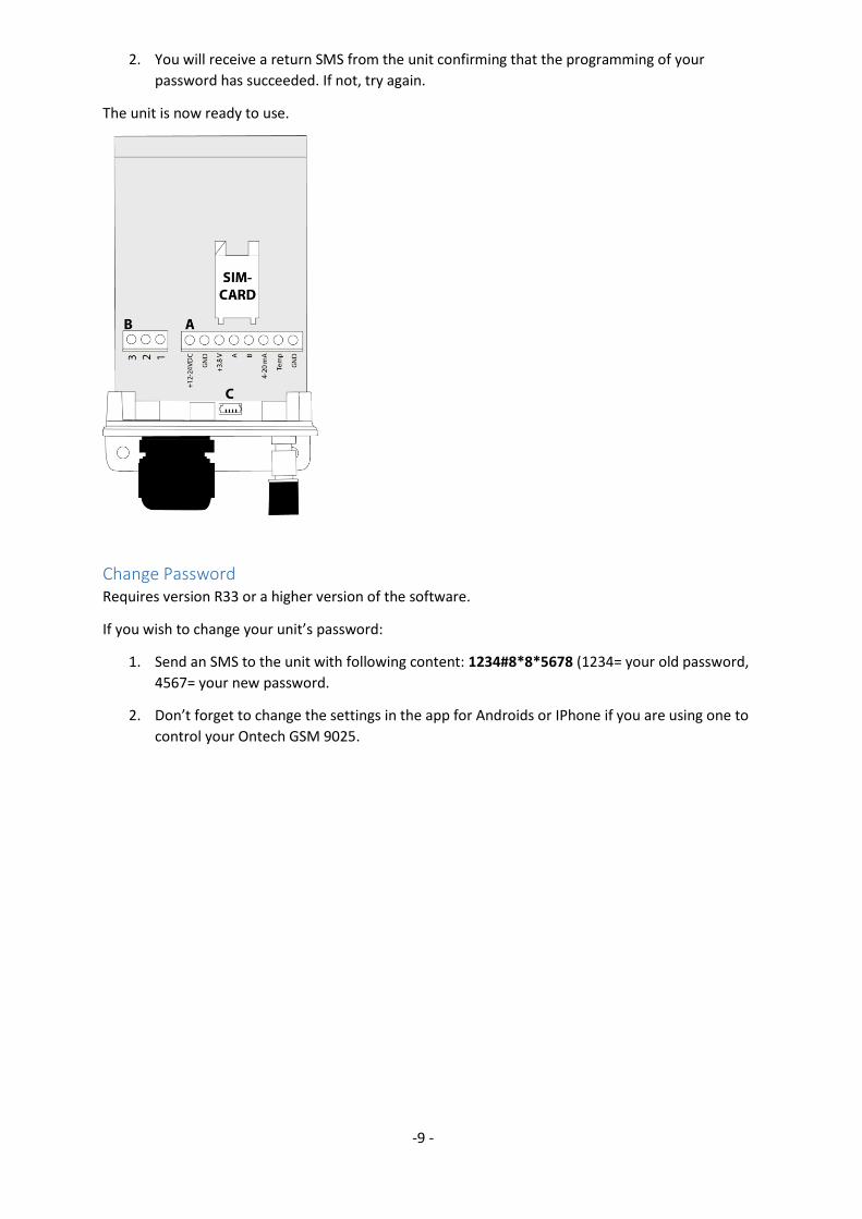
Installing the unit 1. Connect the antenna to the unit.
2. Place the unit where you want to install it and attach it with two screws in the lower screw
holes. The antenna should be facing down.
3. Open the unit by unplugging the two screws that is positioned on the sides of the bottom of
the unit.
4. Carefully pull off the “plastic hood” from the unit to be able to reach the SIM- card holder. Be
careful when pulling the shell off because there is a possible risk that the flat cable might lose
its attachment.
-8 -
5. Open the SIM-card holder by dragging it down until there is a click.
6. Fold up the upper part.
7. Insert the SIM-CARD in the upper part (the up folded part). The cut corner shall be positioned
in the upper left corner when the upper part is folded down
8. Fold down and drag the upper part up until there is a click. The SIM-card is now locked into
position.
9. Open the screw cap by turning it counter clockwise.
10. Pull the cables through the screw cap.
11. Connect the number of units that you wish to use:
a. Power. Terminal A, 12VDC. Use either the power adapter or a 12V accumulator or
both. Plus (white cord) is connected to the connector “+12-24VDC”. Minus (black
cord) is connected to the connector “GND”. 24VAC does work, though it might
damage the unit if the higher voltage than 27VAC is connected to the unit.
Important. Do not connect to a power source at this stage. This might cause
damage to the equipment.
b. Relay. Terminal B. If you want “Normally Open Relay” (Closing relay) use connector 2
and 3. If you want “Normally Closed Relay” (breaking relay) use connector 1 and 3.
Maximum load is 230VAC 10A.
Important. If you shall connect main power, contact a professional electrician.
c. Alarm. Terminal A. Alarm A is connected to connector “+3.8V” and “A”. Alarm B is
connected to the connector “3.8V” and “B”.
d. External temperature is connected between “Temp” and “GND”- connectors.
e. Connect the GPS receiver to terminal “C”.
12. When all the cables are in place, simply turn the screw cap clockwise to create a tight seal.
You can also use plastic tape around the bundle of cables to create a thicker and tighter seal.
13. Pull the hood over the unit and make sure that no cords are pinched or jammed. Put the
screws back into their positions. Also attach a screw in the hole on top of the hood.
14. Connect the power cable to the accumulator and/ or the power adapter to the mains.
a. Make sure that the green lamp starts to flash for about 15 seconds. This indicates
that the unit is searching and is trying to connect to a GSM network.
b. The unit is connected to the GSM network when the green lamp is showing a
constant green light and the unit is now ready for use.
Notice. If the green and the red lamp keeps flashing this means:
No SIM card is inserted.
The PIN code of the SIM card has not been deactivated.
The SIM card has not been inserted properly.
Choose a Password To communicate with the unit you must choose a password. This is to make sure that no
unauthorized should be able to connect to the unit. The password contains four digits.
1. Create a password by sending an SMS to the unit with four digits. These four digits is stored
within the unit and is your password. This is to guarantee the units confidentiality.
-9 -
2. You will receive a return SMS from the unit confirming that the programming of your
password has succeeded. If not, try again.
The unit is now ready to use.
Change Password Requires version R33 or a higher version of the software.
If you wish to change your unit’s password:
1. Send an SMS to the unit with following content: 1234#8*8*5678 (1234= your old password,
4567= your new password.
2. Don’t forget to change the settings in the app for Androids or IPhone if you are using one to
control your Ontech GSM 9025.
-10 -
Using apps
There are apps for Android phones and IPhone to remotely control your Ontech units.
In the Android app the functions are completely integrated and is not showing the SMS created or
received. All the settings can be changed and modified in the app. The Android app can also handle
up to twenty different Ontech GSM main units.
The IPhone app requires you to confirm the SMS and is pressing the send button manually. The
receiving of the SMS happens manually and the information cannot be read into the app
automatically. The change of settings is made through the iPhone internet browser (Safari).
Both apps are compatible with the Ontech GSM main units and older versions.
Important. The apps are using SMS and the price for these are according to your mobile
subscription or prepaid card.
Installation and settings of the Android app
Installing the app The app is available on Google Play and is called Ontech Control. Download it and follow the
instructions given to install the app on your Android phone. You can also use the QR code on the
back of this manual or of the bottom of the box to quickly get to the right page for downloading.
First time settings When you start up the app and receive the message “Update my system info” choose Do not update.
If the settings menu does not show when you open the app, proceed as following:
Press your phones general button for settings or the three squares in the top corner of the
screen. Four different options will appear on the screen. Press Settings.
When you have entered the page Settings for main units:
1. Press Number of units if you wish to control more than one Ontech GSM main unit. Select
how many units you want to control.
2. Press GSM Master 1 (Master1) to set the first main unit.
3. Press Name and name your main unit, example; Ski lodge or Summer House. Confirm by
pressing OK.
4. Press Phone number and type in the phone number to your Ontech GSM units SIM card.
Confirm by pressing OK.
5. Press Password and type in your four digit password that you have assigned to your Ontech
GSM unit (See Choose a Password on page 8). Confirm with OK.
6. If you have any slave units (See Accessory units on page 5) make sure you tick the box
referring to the ID number for the slave. If you don’t do this, the app will add all the units it
will find automatically.
7. When you are finished press the Android back button.
If you wish to set more GSM master units, repeat number 2-7 above.
-11 -
When all the settings are done, return to the main page in the app by pressing the general Android
phone back button.
The settings are now finished and you are ready to use your app to control and manage your Ontech
GSM 9025.
Installation and setting of the iPhone app
Install the app Download the app Ontech Control from Appstore and install on your iPhone according to the
instructions.
You can also use the QR-code you find on last page in this manual or on the underside of the package
to get fast access to the download page.
Settings the first time If you not are directed to the setting page when opening the app the first time:
Click Settings in the lower part of the screen.
The screen Settings is shown.
1. Click Phone Number and write the phone number to the SIM-card installed in the Ontech
GSM master unit. Confirm with OK.
2. Click Password and write the four digit Password you have programmed the Ontech GSM
master unit (see Choose a Password on page 8).
3. If you have any accessories (see Accessory units on page 5) so mark the ID numbers of the
accessories in the list.
When all settings are done you will return to the Main Page by click on the Main-button.
You are now done with the settings and the app is ready to use to control your Ontech GSM 9025.
-12 -
Functions
Ontech GSM 9025 is a mobile product with many different functions that can be programmed. Below
you will find a list of available functions. Ver. refers to the software version where the function is
available. To check which software version your unit have, see Master Functions on page 28.
Name Description Ver
Temperature Below
Alarm
The temperature alarm will alert you when the temperature around
your unit falls below the selected temperature. If the alarm has been
triggered the unit will not reset until the temperature will increase
above the given temperature.
Example: If the selected temperature is 5 degrees and the
temperature falls below that, the unit will alert you. The unit will not
alarm again before the temperature has been at least up to 6
degrees.
34
Temperature
Above Alarm
Temperature alarm can also alert you when the temperature reaches
above the selected temperature. If the alarm has been triggered the
unit will not reset until the temperature will drop down to below the
given temperature.
Example: If the temperature has been set on 25 degrees, the unit will
alert you when it reaches 26 degrees. The unit will not alarm again
until the temperature has dropped down to at least 24 degrees.
34
Select Active Sensor
The Ontech GSM 9025 contains an internal temperature sensor
which is used to control thermostats and temperature alarms. You
can choose to connect an external temperature sensor to the unit
(See External temperature sensor on page 6) and let it control
temperature alarm and thermostat instead.
34
Alarm Delay If an alarm sensor is connected to a unit or an extra unit it will send
an alarm directly when the alarm sensor is triggered. In some cases
it is desirable to delay the alarm. You can choose to delay the alarm
between 1 and 255 seconds. This delay function is often used at
doors that is alarmed.
34
Auto Relay This function will make the relay activate if an alarm has been
triggered. Can also be set to be turned off when an alarm is
triggered.
Example: An alarm horn is connected to the relay. When the alarm is
triggered the horn is activated and will sound.
Example: A temperature alarm has been triggered. When the
temperature goes below the set temperature a radiator that has
been connected to the relay activates.
32
-13 -
Alarm Input
Settings
Alarm units such as IR detectors, magnet switch and fire alarms, etc
that is connected to the Ontech GSM 9025 must have a closing
(Normally Open, NO) or breaking (Normally Closed, NC) function.
You must choose NO or NC when connecting an alarm to the unit.
NO is preset.
34
Powerfail If a power failure should occur, an alarm will be sent one minute
after to all the phone numbers on the Alarm List (See Power fail
alarms on page 23).
34
With Power Failure you can choose a time between 0 and 40
minutes before an alarm message will be sent to you. If the power
comes back within that given time, the alarm message will not be
sent.
Example: The unit is installed in a place with a lot of short power
failures. By setting the Power Failure to 15 minutes, the unit will only
alarm if the power has been gone for more than 15 minutes.
34
Radio When the unit is delivered the short range radio is activated. If you
want you can turn it off as it may save you some power.
34
Radio channel The short range radio that is used to communicate with the extra
accessories Ontech Relay 9010 and Ontech Alarmbox 9012, can be
set to different radio frequencies. Channels 0- 15 can be set. It is
important that the main unit is set to the same channel as the other
units in the Ontech system in order to communicate with each
other.
34
Units for timer You can set a delayed deactivation of the relay when you have
activated it between 1 and 99 hours (See Controlling the unit on
page 17).
With this function you can select 1-99 minutes or 1-99 seconds
instead.
34
Battery message When the battery is low an alarm message will be sent to all the
numbers on the alarm list. If you don’t want to keep receiving this
message you can simply turn it off.
34
Status number When requesting a status from the unit (See Status - SMS on page
28) it will normally be sent to the phone that requested it. With the
function Status the unit will instead send the status to a specific
phone number of your choice.
34
24V Voltage If you are powering your unit with a 24V accumulator you must
activate the 24V setting to receive battery alarm when the voltage
from the accumulator drops.
34
Alarm, flashing When the units alarm is activated a red light will start to flash. With
this function you can simply turn the flashing light off when the
alarm triggers.
34

-14 -
GPS fence This functions lets you activate and set the area on a so called GPS
fence. If the unit moves outside this area the alarm will activate and
alert all the phone numbers on the alarm list.
34
Sensor 4-20mA The unit can be used to measure and alarm at different levels of
current between 4-20 mA. If the unit are going to be used in such
ways, please contact the provider at [email protected]
34
-15 -
Function settings
Set the functions with an Android telephone 1. Launch the app Ontech Control.
2. If a screen appears ”Update my system info”, select Do not update.
3. Press the Android general button for setting. Four buttons will appear. Select Master
Functions.
4. The screen GSM Function appears.
5. There are three tabs on the top of the page; General, Alarm numbers and Advanced functions
6. For programing the Alarm list under the tab Alarm numbers, see Store numbers in the alarm
list with an Android telephone on page 20. It is necessary to program the Alarm list in order
to receive alarm messages.
7. Under the tab General you find the most used functions. Make the settings by pressing the
bar with the functions you want to set and enter a value or make a choice. Then press OK.
8. When all settings has been done scroll down to the bottom of the screen and press the Apply
button. The new settings are now sent to and stored in the unit. The unit restarts with the
new settings. All this takes about one minute. An SMS is sent to the telephone to confirm
that the settings has been stored (Settings successfully updated).
9. If you wish to do settings under the tab Advanced functions, select the tab and repeat 7 and
8.
10. When all settings are done, return to the Main screen by pressing the Android general Back
button.
Set the functions with an iPhone 1. Launch the app Ontech Control.
2. Press the button Settings on the lower part of the screen..
3. Press the button SIM settings. An alert panel appears. Select Ontech GSM 9025 or 9035.
4. A website named Setting your Ontech Unit opens in the web browser Safari. Tilt the iPhone
to landscape screen position in order to make the text more easily read.
5. There are three subpages for settings: General, Alarmlist and Advanced. Select with the
buttons at the bottom of the page.
6. For programing the Alarm list under the tab Alarm numbers, see Store numbers in the alarm
list with an iPhone or other smartphone on page 20. It is necessary to program the Alarm
list in order to receive alarm messages.
7. On the page General you will find the most used functions. Press the button.
8. Fill in your Password (see Choose a Password on page 8) in the field on the top of the page.
9. Then make all settings you want to do.
10. When ready, press Create Code
11. In the box the code will appear.
12. Open the Message app on the iPhone.
13. Create a new text message.
14. Fill in the number to the unit.
15. Paste the code in the message field.
16. Press Send.
17. The new settings are now sent to and stored in the unit. The unit restarts with the new
settings. All this takes about one minute. An SMS is sent to the telephone to confirm that the
settings has been stored (Settings successfully updated).
18. If you wish to do settings under the tab Advanced functions, press the button.
19. Repeat 8-17.
-16 -
Important! If you want to change a setting of a function you must also set all other functions you
earlier have set under the tab. The unit will store the information on the setting page and will not
remember earlier settings. Example: If you set a temperature alarm earlier and then you want to
set the alarm delay, you have to set both functions again. The unit only remembers the settings
from the latest SMS sent from each page.
Set the functions with a Smartphone 1. Launch the telephones web browser. Go to the page http://www.ontechgsm.com/set.html.
2. A website named Setting your Ontech Unit opens in the web browser Safari. Tilt the iPhone
to landscape screen position in order to make the text more easily read.
3. There are three subpages for settings: General, Alarmlist and Advanced. Select with the
buttons at the button of the page.
4. For programing the Alarm list under the tab Alarm numbers, see Store numbers in the alarm
list with an iPhone or other smartphone on page 20. It is necessary to program the Alarm
list in order to receive alarm messages.
5. On the page General you will find the most used functions. Press the button.
6. Fill in your Password (see Choose a Password on page 8) in the field on the top of the page.
7. Then make all settings you want to do.
8. When ready, press Create Code
9. In the box the code will appear.
10. Open the Message app on the smartphone (Iphone only).
11. Create a new text message.
12. Fill in the number to the unit.
13. Paste the code in the message field.
14. Press Send.
15. The new settings are now sent to and stored in the unit. The unit restarts with the new
settings. All this takes about one minute. An SMS is sent to the telephone to confirm that the
settings has been stored (Settings successfully updated).
16. If you wish to do settings under the tab Advanced functions, press the button.
17. The repeat 8-17.
Important! If you want to change a setting of a function you must also set all other functions you
earlier have set under the tab. The unit will store the information on the setting page and will not
remember earlier settings. Example: If you set a temperature alarm earlier and then you want to
set the alarm delay, you have to set both functions again. The unit only remembers the settings
from the latest SMS sent from each page.

-17 -
Controlling the unit
Controlling with an Android phone 1. Open the app Ontech Control.
2. If you receive a message telling you “Update my system info” then choose Do not update.
Choose this if you wish to make the unit send a SMS with a status that is scanned into the
app. This will make you able to see the current status.
3. You will now reach the main page. Here you can:
a. Choose which unit to control if you have set the app to control more than one unit: Press
Master 1 (Or the name you have chosen) and choose which unit you would like to work
with.
b. Turn on or turn off the alarm function: Press Alarm, choose Activate alarm or Deactivate
alarm. You can also do this by pressing directly on the icon.
c. Reset an alarm: Press Alarm and choose Acknowledge alarm.
d. Turn on or turn off a relay on the main unit or 230V output on any of the extra relays
Ontech Relay 9010/9015 if you have one connected to the system: Press on the current
unit and choose Relay ON or Relay off. With the function Set relay you can set the relay
to go and off automatically after a certain time (timer function). Set a number between
1- 99. The unit is preset on hours. If you would like to choose minutes or seconds as a
unit you must first change that under functions (See Set the functions with an Android
telephone on page 15).
e. Set the Thermostat function. This requires that you have a radiator connected to the
relay on the main unit (See Thermostat function on page 25), (extra relay Ontech Relay
9010 cannot be controlled with this function). Press the button Thermostat and then Set
thermostat and specify a degree between 0 and 29 degrees. If you would like to
disconnect the thermostat, simply press Thermostat off.
f. GPS function. Press the GPS function and then Get GPS Position to receive the position,
direction and speed of the unit.
4. After you have chosen the commands you must send these to the unit. You can do this in
two different ways:
a. Press Apply. The commands will be sent in a SMS and implemented.
b. Press Update. The commands will be sent in a SMS and implemented. After that the unit
will send back a SMS to the phone that will be scanned into the app. The main page on
the app will then be updated with the current information from the unit (See Status -
SMS on page 28).
You can control certain settings on the unit by pressing Master Functions and choose Get
Master Functions. Then press Apply on the main page. A SMS will be sent to the unit that
will reply with a SMS that will show the current settings. These settings will then be shown
on the screen (See Master functions on page 29).
-18 -
Controlling with an iPhone 1. Open the app Ontech Control.
2. You will now reach the main page. Here you can:
a. Turn on or turn off the alarm function: Press Alarm, choose Activate alarm or Deactivate
alarm. You can also do this by pressing directly on the icon.
b. Reset an alarm: Press Alarm and choose Acknowledge alarm.
c. Turn on or turn off a relay on the main unit or 230V output on any of the extra relays
Ontech Relay 9010/9015 if you have one connected to the system: Press on the current
unit and choose Relay ON or Relay off. With the function Set relay you can set the relay
to go and off automatically after a certain time (timer function). Set a number between
1- 99. The unit is preset on hours. If you would like to choose minutes or seconds as a
unit you must first change that under functions (See Set the functions with an iPhone on
page 15).
d. Set the thermostat function. This requires that you have a radiator connected to the
relay on the main unit (See Thermostat function on page 25), (extra relay Ontech Relay
9010 cannot be controlled with this function) Press the button Thermostat and then Set
thermostat and specify a degree between 0 and 29 degrees. If you would like to
disconnect the thermostat, simply press Thermostat off.
e. GPS function. Press the GPS function and then Get GPS Position to receive the position,
direction and speed of the unit.
f. After you have chosen the commands you must send these to the unit. You can do this in
two different ways:
g. Press Apply. The commands will be sent in a SMS and implemented.
h. Press Update. The commands will be sent in a SMS and implemented. After that the unit
will send back a SMS to the phone that will be scanned into the app. The main page on
the app will then be updated with the current information from the unit (See Status -
SMS on page 28).
You can control certain settings on the unit by pressing Master Functions and choose Get
Master Functions. Then press Apply on the main page. A SMS will be sent to the unit that
will reply with a SMS that will show the current settings. These settings will then be shown
on the page (See Master functions on page 29).
Controlling with SMS You can control the unit by sending SMS. Below is a list of the commands.
All SMS messages must start with your Password (see Choose a Password on page 8) followed by the
sign #.
In the table below we use the Password 1234 but you change it to your Password.
Command SMS-text Comment
Turn on the 230 V outlet 1234#1*1#
Turn off the 230 V outlet 1234#0*1#
-19 -
Turn on the 230 V oulet on master unit with delay
1234#1*1*T# Turn on the 230 V outlet with delay. (T=1-99, default hours, but can be set to minutes or seconds. See Functions on page 12.
Turn on the 230 V outlet on an Ontech Relay 9015
1234#1*6# Turn on the 230 V outlet in an Ontech Relay 9015 with ID 6.
Turn off the 230 V outlet on an Ontech Relay 9015
1234#0*6# Turn off the 230 V outlet in an Ontech Relay 9015 with ID 6.
Activate the Alarm function 1234#7*1#
Deactivate the Alarm function
1234#7*0#
Confirm an alarm 1234#9#
Request status 1234#8# The unit replies with up to date information of the status, see Status - SMS on page 28.
Reguset Master settings 1234#8*2# The unit replies with an SMS with Master function settings, see Master functions on page 29.
Set the Thermostat 1234#2*D# D = the degree Celsius of your choice (0-29 allowed)
Turn off the Thermostat 1234#2#
Two or more commands can be written in the same SMS, just write them after each other and
separate the commands with the sign #.
Example: You want to turn on the relay in the main unit and turn off the relay of the Ontech Extra
Relay with ID 3.
1234#1*1#0*3#
-20 -
Alarm
There are three types of alarms:
From alarm sensors connected to the main unit or one of the optional equipment (see
Accessory units on page 5)
Temperature alarms
Power fail alarms
Alarm list The unit must know where to send the alarm messages so you have to store the mobile numbers in
an Alarm list. Up to 9 different numbers can be stored.
Store numbers in the alarm list with an Android telephone 1. Launch the app Ontech Control.
2. If a screen appears asking ”Update my system info”, select Do not update.
3. Press the Android general button for setting. Four buttons will appear. Select Master
Functions.
4. The screen GSM Function appears.
5. There are three tabs on the top of the page; General, Alarm numbers and Advanced functions
6. Select the tab Alarm numbers.
7. Select the first row with Alarm number and write the first number in the Alarm list. Select
OK.
8. If you want to add more numbers, repeat the procedure on the below rows.
9. When you have added all the numbers you want, browse to the bottom of the screen and
select Apply. An SMS is now sent to the unit with the new settings. After about one minute
an SMS will be sent from the unit to the telephone confirming that the setting has been done
(Settings successfully updated).
10. When all settings is done, return to the Main screen by pressing the Android general Back
button.
Store numbers in the alarm list with an iPhone or other smartphone 1. Launch the telephones web browser. Open the page http://www.ontechgsm.com/set.html.
2. A website named Setting your Ontech Unit opens in the web browser Safari. Tilt the
telephone to landscape screen position in order to make the text more easily read.
3. There are three subpages for settings: General, Alarmlist and Advanced. Select with the
buttons at the bottom of the page.
4. For programing the Alarm List select the tab Alarm numbers
5. Fill in your Password (see Choose a Password on page 8) in the field on the top of the page.
6. Then fill in all numbers to the Alarm list.
7. When ready, press Create Code
8. In the box the code will appear.
9. Open the Message app on the iPhone.
10. Create a new text message.
11. Fill in the number to the unit.
12. Paste the code in the message field.
13. Press Send.
14. The new settings are now sent to and stored in the unit. The unit restarts with the new
settings. All this takes about one minute. An SMS is sent to the telephone to confirm that the
settings has been stored (Settings successfully updated).
-21 -
Important! If you want to change a number in the alarm list you must also write in all the other
numbers in the Alarm list. The unit will only store the information in the last Alarm list sent.
Activate and deactivate the alarm function When the unit starts up by connecting it to a wall socket the alarm function is not activated by
default. To activate the alarm function you must send a command to the unit, see Controlling the
unit on page 17. To deactivate the alarm function you must also send a command.
The power fail alarm is by default activated. If you want to deactivate it, use the command Powerfail,
see Functions on page 12.
Acknowledge alarms When an alarm has been sent after an alarm sensor has been activated you must acknowledge the
alarm before the unit will send another alarm message. No alarm sensor shall be active when the
alarm is acknowledged. See how to do this under Controlling the unit on page 17. You can also
acknowledge the alarm by pushing the button on the unit.
Temperature alarms cannot be acknowledged. The unit automatically reset the alarm when
temperature reach the set temperature plus or minus one degree.
Powerfail alarms and Battery alarms cannot be acknowledged.
Wired alarm sensors Different types of wired alarm sensors can be connected to Ontech GSM 9025. The unit has two
alarm inputs. Default setting is Normally Open (NO). If the alarm sensors you connect are of the type
Normally Closed (NC), you have to set this (See Functions on page 12).
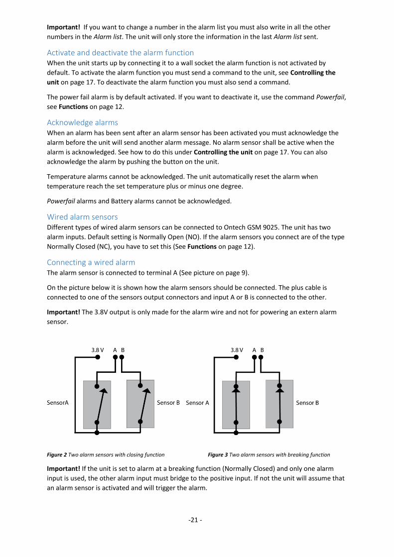
Connecting a wired alarm The alarm sensor is connected to terminal A (See picture on page 9).
On the picture below it is shown how the alarm sensors should be connected. The plus cable is
connected to one of the sensors output connectors and input A or B is connected to the other.
Important! The 3.8V output is only made for the alarm wire and not for powering an extern alarm
sensor.
Figure 2 Two alarm sensors with closing function Figure 3 Two alarm sensors with breaking function
Important! If the unit is set to alarm at a breaking function (Normally Closed) and only one alarm
input is used, the other alarm input must bridge to the positive input. If not the unit will assume that
an alarm sensor is activated and will trigger the alarm.
-22 -
Delay of wired alarms You can set an alarm to send the alarm after a pre-set time. This is practical if you have an alarm
sensor on your outdoor and have to open it before you can turn of the alarm, see Function settings
on page 15.
Alarm from a wired alarm sensor When an alarm sensor is activated an SMS will be sent to all numbers on the Alarm list. Android
telephones with the app installed will also receive a graphic presentation in the app.
Alarm SMS
An alarm SMS contains information about the alarm.
The example in the table below says that both of the alarm inputs A and B has been activated in the
main unit (ID no 1) and that the alarm sensor connected to the B input still is activated.
NB. There will be more information in the SMS.
Text in SMS – example Explanation
Alarm: This row will be shown only if an alarm sensor has been activated
1ab This row indicates the unit (ID 1 in this example) and the alarm inputs (A and B in this example) that has been activated.
Inputs: This row will be shown only if an alarm sensor has been activated
1a This row indicates which unit ID and which alarm input that is still activated.
Alarm message to an Android telephone
If the app Ontech Control is installed there will be a voice message saying “Ontech Alarm”
On the main screen the background of the icon for the alarm will be red.
The icons for the alarm inputs (rings) will be green if the alarm sensor still is activated. The
background of the icons for the alarm inputs will be red if they have been activated.
Temperature alarm Ontech GSM 9025 can be set to send an alarm message if the temperature rise above or decrease
below the set temperature value. All temperature measurements and settings will use Celsius
degree.
Setting of the alarm temperature is done under functions, see Function settings on page 15. The
value range is -30 to +40 degrees.
You can also select which temperature sensor that controls the temperature alarm, see Function
settings on page 15.
Temperature alarms from the unit When the temperature measured by selected temperature sensor will reach the set temperature an
SMS will be sent to all mobile numbers on the Alarm list. Android telephones with the app installed
will also receive a graphic presentation in the app.
Temperature alarm SMS
A temperature alarm SMS contains information about the alarm. The example in the table below says
that the temperature set is reached.
NB. There will be more information in the SMS.
-23 -
Text in SMS – example Explanation
Alarm: This row will be shown only if an alarm sensor has been activated
IntTemp Indicates that a temperature alarm has been activated by the internal temperature sensor. If the text is ExtTemp instead, it is the external sensor that has triggered the alarm.
5;-- Indicates the present temperature, the first value is the internal temperature sensor, the second value (if there is any) is the external temperature sensor.
Temperature alarm to an Android telephone
If the app Ontech Control is installed there will be a voice message saying “Ontech Alarm”
On the main screen the background of the icon for the alarm will be red.
The background of the temperature value will be red to show the temperature measured by the
temperature sensor.
Power fail alarms In the unit there is an internal backup battery (see Backup battery on page 30) that will power the
unit if there is a main power failure. One minute after a power break the power fail alarm message
will be sent to all numbers on the Alarm list with the message “No main Power”. You can set how
many minute you want to delay the power fail alarm. Do this with the Powerfail function (see
Function settings on page 15).
When the main power is restored you will receive a news message saying “Main Power restored”.
The backup battery can power the unit 10-20 hours. When the internal battery is low a message will
be sent to all numbers on the Alarm list with the text ”Internal battery empty”. Unit shuts down”.
Then the unit disconnects from the GSM network and turns off.
On Android telephones with the Ontech Control app installed there will be a graphic presentation of
the messages.
The power fail alarm function is activated by default and will thus work also when the general alarm
function not is activated.
All wired and wireless alarms will still work when the unit is powered by the internal backup battery.
The 230 V outlet is turned off when there is a power fail. The outlet will return to the same position it
had before the fail when the power is restored.
GPS alarm The GPS alarm is a function that will alarm when the unit has moved outside a specific area. This area
is circle based and has a radius of at least 50 meters. The radius can also be multiplied (50m, 100m,
150, etc.).
At www.ontechgsm.com you will find information regarding which GSM receiver that is compatible
with our products. In most cases an adapter is necessary. The adapter is connected to plug C (See
picture on page 9)
With the function GPSFENCE (See Function settings on page 15) you can set the size of the area you
wish to guard. The unit will alarm when the unit is moving outside the area for more than one minute
after it has been activated.

-24 -
-25 -
Other functions
Thermostat function The Thermostat function controls relay with input values from the temperature sensor. If you
connect a radiator or similar to the relay and turn on the Thermostat function (see Controlling the
unit on page 17) the unit will automatically turn on when the temperature drops one degree below
the set temperature value and turn off when the temperature rise one degree above the set
temperature value.
Values between 0 and 29 degrees are permitted.
The Thermostat function is turned off by sending a command to the unit (see Controlling the unit on
page 17) or by pushing the button on the unit.
Garage Opener function for Android Important! Can only be operated from Android telephones with the Ontech Control app installed.
This function differs between Android and Iphones. Below contains a description for the Android
phone. For Iphone, see Garage opener for Iphone on page 26.
With this function you can make the unit recognize up to three mobile numbers. When any of these
numbers are calling the unit the relay will turn on for one second and then turn off without
answering the call. This function can be used to open a garage gate when an approved person calls
the unit.
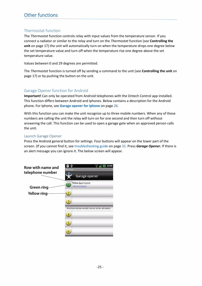
Launch Garage Opener Press the Android general button for settings. Four buttons will appear on the lower part of the
screen. (If you cannot find it, see troubleshooting guide on page 31. Press Garage Opener. If there is
an alert message you can ignore it. The below screen will appear.
-26 -
Add a user to the list 1. Press on the row for the position you want to add. You can add up to three different mobile
numbers on position 1-3
2. A new screen appears.
3. Write the name and mobile number in the fields.
4. Press Send number to GSM unit.
5. An SMS with the settings is now sent to the unit.
6. The unit is returning an SMS that is read into the app. The ring will now turn from yellow to
green and the name and number will appear on the row. This is a confirmation that the
information has been stored in the unit.
7. Repeat if you want to add more users.
8. Press the Android general Back button to go back to the main screen.
Erase a user from the list 1. Press on the row for the position you want to add. A new screen appears.
2. Press Erase position from unit
3. An SMS with the settings is now sent to the unit.
4. The unit is returning an SMS that is read into the app. The name and number will disappear
on the row. The ring is still green. This is a confirmation that the information has been stored
in the unit.
5. Repeat if you want to erase more users.
6. Press the Android general Back button to go back to the main screen.
Get information of users from the unit If you are not sure about which information the unit has stored you can retrieve it.
1. Press on the row for the position you want to retrieve information about. A new screen
appears.
2. Press Get position from unit
3. An SMS with the settings is now sent to the unit.
4. The unit is returning an SMS that is read into the app. The information will show on the row.
5. Repeat if you want to retrieve information of other positions.
6. Press the Android general Back button to go back to the main screen.
Garage opener function for Iphone Important! Can only be operated from Android telephones with the Ontech Control app installed.
This function differs between Android and Iphones. Below contains a description for the Iphone. For
Android, see Garage opener for Android on page 25.
With this function you can make the unit recognize up to three mobile numbers. When any of these
numbers are calling the unit the 230 V outlet will turn on for one second and then turn off without
answering the call. This function can be used to open a garage gate when an approved person calls
the unit.
Add a user to the list 1. Press on the row Garage Opener on the main page.
2. Press on the row Add number.
3. Write the mobile number in the field.
4. Choose position 1-3 where the number should be stored.
5. Press Apply on the main page.
6. The message page will now be opened with a complete SMS to the unit. Press Send.
-27 -
7. The unit is returning an SMS with the information about position and the last 6 digits in the
phone number that was added.
Erase a user 1. Press on the row Garage Opener on the main page.
2. Press on the row Delete Number.
3. Choose position 1-3 and which number that should be deleted.
4. Press Apply on the main page.
5. The message page will now be opened with a complete SMS to the unit. Press Send.
6. The unit is returning an SMS with information about position and what is stored there.
Overheat protection For security reasons the relay will turn off if the measured temperature inside the unit will rise above
70 degrees C. An SMS with the message ”Overheated” will be sent. If this happens, check the relay
and the connected equipment carefully.
Sensor Ontech GSM 9025 is prepared to measure current 4-20 mA or voltage 0-10 V and report the value
back to user and can also be set for sending alarm messages at pre-set values.
Special adapters connected to the external temperature sensor contact is needed to use this
function.
Contact Onvako AB on [email protected] for more information.
GPS function Ontech GSM 9025 is prepared to connect to a GPS receiver. Receivers with a DIN contact of the type
PS/2 is connected to an Ontech GPS adapter that is connected to terminal C (See picture on page 9).
In the Android app you will find the GPS button on the main page. By pressing the button Get GPS
Position you will receive the unit’s position, speed and course. In the Android app the position will
also presented on a map.
Information can also be retrieved by sending an SMS with the following content to the unit:
1234#8*1#. The unit will return with information of position, speed and direction.
The GPS function can be used to set a GPS alarm (See GPS alarm on page 23).
Others
The lamps Ontech GSM 9025 has two lamps
Green lamp Constant light – indicates that the unit is connected to the GSM network.
Blinking – the unit is searching the GSM network.
Red lamp Off – the relay is turned off.
Constant light – the relay is turned on.
Blinking – an alarm sensor has been activated and the alarm has not yet been confirmed.

-28 -
Both lamps Blinking – the SIM card does not work. See
Trouble shooting guide on page 31.
The push button Software version R32:
Turn on and turn off the relay.
Turn off Thermostat function if activated.
Press for 30 seconds to turn the unit off.
Software version R33 or higher
Turn on and turn off the relay.
Turn off Thermostat function if activated.
Press the button for 5 seconds and both lamps start to blink. Release the button. The unit
disconnects from the GSM network and turns off.
Status - SMS Request for a status SMS is made by sending an SMS as follows:
1234#8# (1234=your Password) or by pressing UPDATE in the apps for Android and iPhone.
The unit return an SMS
In the app for Android telephones the information is read into the app and is shown graphically.
The SMS contains some of the information below, depending of the status of the u nit.
Text in SMS – example Explanation
*Ontech 9025 – Ver 34 * indicates that the alarm function is activated. Ver 34 is the software version.
Alarm: This row appears only if there is an alarm unconfirmed.
1ab Indicates the unit (in this example ID1) and the alarm inputs that has been activated (A and B)
1/IntTemp Indicates that a temperature alarm has been activated by the internal temperature sensor and the ID no of the unit that triggered the alarm. If the text is ExtTemp instead, it is the external sensor that has triggered the alarm.
Inputs: This row appears only if there is an active alarm sensor.
1a Indicate the unit and alarm sensor input that still is active.
Units:
1*/23/21 2/15/-- 3/21
Indicates which components there is in the system, the status of the outlet and the temperature 1*/23/21 indicates that the master (ID1) outlet is activated (*), the internal temperature sensor is 23 degrees and the external temperature sensor is 21 degrees. 2/15/-- indicates an extra relay Ontech Relay 9015 with ID no 2, the outlet is not activated and the internal temperature sensor is 15 degrees. There is no external temperature sensor. 3/21 indicates an Ontech Alarmbox 9012 with ID no 3 and the temperature sensor is 21 degrees.

-29 -
Thermostat:
1/24 Thermostat, OFF= turned off. If it is activated a value 0-29 will be shown. This is the set thermostat temperature.
Important! Under Units: is shown the extra units (Ontech Relay 9010, Ontech Relay 9015 and Ontech
Alarmbox 9012) that is connected to the main unit with the short range radio. If these units loose
contact with the main unit it can take up to one hour before this information is shown in the status
SMS.
Master functions Request of some of the settings is made by sending an SMS as follows:
1234#8*2# (1234=your Password) or by pressing Master functions on the main screen in the apps
for Android and iPhone.
The unit returns an SMS.
In the app for Android telephones the information is read into the app and is shown under Master
functions.
The SMS contains the following information:
Text in SMS – example Explanation
*Ontech 9025 – Ver 34 * indicates that the alarm function is activated. Ver 34 is the software version.
Radio channel: 0 Shows the set channel on the short range radio
Power fail: 1 Indicates the delay of the power fail alarm in minutes. See Power fail alarms on page 23.
Radio channel: 0 Shows the set channel on the short range radio
Sensor: OFF Indicates if the 4-20 mA sensor is activated in the temp input jack. See Sensor on page 24.
Units:
1/INT/<10/>30/30s/ON/NO Shows in order: ID1/ Internal temp sensor controls alarm and thermostat/ alarms at temperature below 10 degrees/ alarms at temperature above 30 degrees/ delay of alarm on alarm input 30 seconds/ auto relay function activated/ alarm inputs set to Normally Open.
2/EXT/<10/>30/ Shows in order: ID2/ External temp sensor controls alarm and thermostat/ alarms at temperature below 10 degrees/ alarms at temperature above 30 degrees.
Factory reset Factory reset erases all settings in the memory of the unit. All settings including the Password has to
be set again.
1. Disconnect the unit from the main power socket.
2. Press the push button and turn the unit off.
-30 -
3. Wait at least 60 seconds.
4. Press down the button.
5. Connect the unit to the main power socket while still holding the button down.
6. The red lamp blinks 8 times.
7. Release the button.
8. The unit has now been restored to factory settings and starts to search for the GSM network.
9. Start using it by setting the Password, see Choose a Password on page 8.
Backup battery There is a backup battery in the unit that power the unit in case of a main power failure. One minute
after a main power failure an SMS is sent to all mobile numbers on the Alarm list with the message
”No main Power”. You can set how many minutes delay you wish before the SMS is sent. See the
Function settings on page 15. When the main power is restored a new SMS with the text ”Main
Power restored” is sent.
The backup battery can power the unit for 10-20 hours. When the battery is low an SMS will be sent
to all numbers on the Alarm list with the text ”Internal battery empty. Unit shuts down”. Then the
unit will disconnect from the GSM network and turn off.
In Android telephone with the Ontech Control app installed these messages will be presented
graphically.
When the unit is powered by the backup battery the 230 V outlet is turned off.
When the main power is restored the 230 V outlet will go back to the position it had before the
power failure.
The alarm functions are still activated during a main power failure.
Powering with Alternating Current The unit can also be powered with 24 ACV .
The connection is made on connection terminal A to connector “+12- 24VDC” and “GND”.
Important! No higher voltage than 27 VAC may be connected. This may cause damage to the unit.
-31 -
Trouble shooting guide
Symptoms Reason Solution
Both lamps are blinking when the unit is connected to the main power
The unit cannot read the SIM card SIM card missing Pincode protection on SIM card not disabled Welcome message from network operator active on SIM card. Disable by ringing one time with the card in a telephone.
The unit do not return status request
Prepaid card has no money Refill the pre paid SIM card
An alarm message is sent even if the alarm sensors are not activated
One alarm input open in Normally Closed mode
If Normally Closed is set and only one alarm input is used, the other has to be connected to the 3.8 V.
The unit cannot connect to extra units Ontech Relay 9010/9015 and Ontech Alarm box 9012
Wrong radio channel set Short range radio disabled
Check all units in the system has the same radio channel set. Check that the short range radio function is turned on.
The unit does not respond on commands
No Password set Wrong Password Wrong mobile number
Check that correct Password is set and that the mobile number is correct.
Cannot find the general Menu button in the Android app
Press the three squares in the upper right corn
Tip
If the unit do not respond on SMS check if it is connected to the GSM network by making a
voice call to it. If it is connected to the GSM network it answer the call with a short beep. If
so, check if there is money left on the prepaid SIM card.
If you are using a prepaid SIM card we strongly recommend you to register it on the website
of the network operator. You will then be able to check the amount on the card and if
needed, refill it.
Let us know if you have any tip, mail at [email protected]
-32 -
Technical specifications
GSM Dual band GSM 900/1800 MHz
GSM subscription All, even prepaid. Operator must operate the GSM network and not
only 3G.
Relay Potential free 230V/10A
Short range radio Frequency 2,4 GHz, Power 1 mW
Alarm inputs Two alarm inputs that can be set to Normally Open or Normally
Closed.
Power 9-30 VDC or 24VAC. Power adapter 13.8 V is included.
Backup battery Built-in 4,2V Lithium Polymer 1100 mA
Power consumption Idle <0,5 W, Maximum 4 W
Temperature operating
range
-40°C to +55°C
Temperature sensor
tolerance at 25 degrees C
Internal temperature sensor +/- 2°C (230 V outlet not activated).
External temperature sensor +/- 1°C
Analogue input For external temperature sensor or 4-20 mA measure adapter
Certified Compliance EMC, LVD and R&TTE directive
Support
If you are experiencing difficulties with the unit, do not hesitate to contact our support on the adress
[email protected] or with a letter to Onvako AB, Datavägen 14A, 43632 Askim, Sweden.
-33 -
QR-codes
Ontech Control for Android Ontech Control for iPhone Settings page for Smartphones
RM
_15
04
5_EN
_15
08
10


![PLANING DIAGRAM WOLFF 9025 · 2014. 3. 24. · 962--4--020928E--2 WOLFF 9025 Series Crane data 2/24 2.2.3.1 Load capacity [kg] data given in distances of meters DIN 15018 / H1 --](https://img.pdfslide.net/doc/110x75/60e68f399b7fd25a6f678ea9/planing-diagram-wolff-2014-3-24-962-4-020928e-2-wolff-9025-series-crane.jpg)