Embed Size (px)
Citation preview
Onyx Ceph ™
Copyrights © Image Instruments GmbH 2001-2007
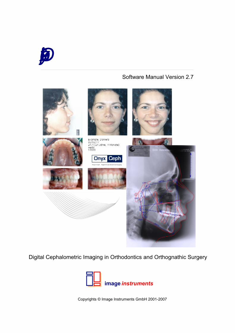
Software Manual Version 2.7
image
Digital Cephalometric Imaging in Orthodontics and Orthognathic Surgery
instruments
All rights reserved. No parts of this work may be reproduced in any form or by any means - graphic,electronic, or mechanical, including photocopying, recording, taping, or information storage and retrievalsystems - without the written permission of the publisher.
Products that are referred to in this document may be either trademarks and/or registered trademarks ofthe respective owners. The publisher and the author make no claim to these trademarks.
While every precaution has been taken in the preparation of this document, the publisher and the authorassume no responsibility for errors or omissions, or for damages resulting from the use of informationcontained in this document or from the use of programs and source code that may accompany it. In noevent shall the publisher and the author be liable for any loss of profit or any other commercial damagecaused or alleged to have been caused directly or indirectly by this document.
Chemnitz, Februar 2007
Onyx Ceph™ - Digital Cephalometric Imaging Software
© Image Instruments GmbH 2001-2007
Onyx Ceph™
Functionality and layout of the software Onyx Ceph™ is aligned tothe workflow in orthodontic diagnostic imaging and treatmentplanning. Most of the implemented features can be customized.The variety of diagnostic and treatment concepts in orthodonticsand oral-maxillofacial surgery may require additional features.Image Instruments is grateful for each such hint and will implementeach new feature that may improve the usability of the software.
Image Instruments GmbHOlbernhauer Str. 5D 09125 ChemnitzGermanyPhone +49 371 9093 140Fax +49 371 9093 149
Support
www.onyx-ceph.de - [email protected]
printed: 06.02.2007
© Image Instruments GmbH 2001-2007
IContents
Table of Contents
Release 1
I Software manual 3
II Preliminary Remarks 5
................................................................................................................................... 61 Developer
................................................................................................................................... 72 Conformity Check
................................................................................................................................... 83 System Requirements
.......................................................................................................................................................... 8Database Server
.......................................................................................................................................................... 8Network Station
.......................................................................................................................................................... 9Single PC
.......................................................................................................................................................... 9Further Components
................................................................................................................................... 104 Installation
................................................................................................................................... 125 License Agreement
................................................................................................................................... 146 Registration
................................................................................................................................... 157 Interfaces
................................................................................................................................... 168 Documentation
................................................................................................................................... 179 Software Support
................................................................................................................................... 1810 Supplementary Programs
.......................................................................................................................................................... 18Onyx Admin
.......................................................................................................................................................... 18Onyx Backup
.......................................................................................................................................................... 18Onyx Config
.......................................................................................................................................................... 19Onyx DB Server
.......................................................................................................................................................... 19Onyx Patch
.......................................................................................................................................................... 19Onyx Register
.......................................................................................................................................................... 19Onyx Uninstall
.......................................................................................................................................................... 19Onyx Update
.......................................................................................................................................................... 20Onyx View
.......................................................................................................................................................... 20Onyx Stat
.......................................................................................................................................................... 20Onyx PVL
III Functionality 23
................................................................................................................................... 241 Hint
................................................................................................................................... 252 Visual Diagnostics
.......................................................................................................................................................... 25Photostat Lateral
.......................................................................................................................................................... 25Photostat Frontal
.......................................................................................................................................................... 26Photostat Smiling
.......................................................................................................................................................... 26Cephalogram Lateral
.......................................................................................................................................................... 27Cephalogram Frontal
.......................................................................................................................................................... 27OPT
.......................................................................................................................................................... 27Hand X-ray
.......................................................................................................................................................... 27Cast Deciduous Dentition
.......................................................................................................................................................... 27Cast Mixed Dentition
.......................................................................................................................................................... 28Cast Permanent Dentition
................................................................................................................................... 293 Treatment Planning
.......................................................................................................................................................... 29Treatment Simulation
IIContents
.......................................................................................................................................................... 29Ricketts VTO
.......................................................................................................................................................... 29Juxtaposition
.......................................................................................................................................................... 30Superimposition
................................................................................................................................... 314 Case Documentation
.......................................................................................................................................................... 31Standard Printing
.......................................................................................................................................................... 31Form Printing
.......................................................................................................................................................... 311:1 Printing
................................................................................................................................... 325 Presentation
.......................................................................................................................................................... 32Album
.......................................................................................................................................................... 32Full Screen
.......................................................................................................................................................... 32Gallery
................................................................................................................................... 336 Communication
.......................................................................................................................................................... 33Exchange
.......................................................................................................................................................... 33Export
.......................................................................................................................................................... 33Report
.......................................................................................................................................................... 33Messages
................................................................................................................................... 347 Training and Education
.......................................................................................................................................................... 34Lexicon
.......................................................................................................................................................... 34Training Client
.......................................................................................................................................................... 34Babylon Glossary
IV Menu bar 36
................................................................................................................................... 371 Patient
.......................................................................................................................................................... 37Select Patient ......................................................................................................................................................... 37Card File......................................................................................................................................................... 38Mailslot
.......................................................................................................................................................... 39New Patient
.......................................................................................................................................................... 39Edit Master Data
.......................................................................................................................................................... 40Delete Patient
.......................................................................................................................................................... 40Patient Attributes
.......................................................................................................................................................... 41New Image
.......................................................................................................................................................... 42Delete Image
.......................................................................................................................................................... 42Image Attributes
.......................................................................................................................................................... 43New Session
.......................................................................................................................................................... 43Delete Session
.......................................................................................................................................................... 43Session Attributes
.......................................................................................................................................................... 43Select Client
.......................................................................................................................................................... 43Log off "User"
.......................................................................................................................................................... 44Exit
................................................................................................................................... 452 Edit
.......................................................................................................................................................... 45Templates
.......................................................................................................................................................... 45Copy Image
.......................................................................................................................................................... 46Copy View
.......................................................................................................................................................... 47Save Image
.......................................................................................................................................................... 47Save View
................................................................................................................................... 493 View
.......................................................................................................................................................... 49Auxiliary Windows
......................................................................................................................................................... 50Panwindow
......................................................................................................................................................... 50Detail
......................................................................................................................................................... 50Show Landmark Name
......................................................................................................................................................... 51Sketch
.......................................................................................................................................................... 51Symbol bars
......................................................................................................................................................... 52Finding Navigator
......................................................................................................................................................... 52Zoom Controller
IIIContents
......................................................................................................................................................... 53Image Processing
......................................................................................................................................................... 53User Buttons
......................................................................................................................................................... 53View Options
.......................................................................................................................................................... 53Image
.......................................................................................................................................................... 54Lines
.......................................................................................................................................................... 54Templates
.......................................................................................................................................................... 55ToolTips
.......................................................................................................................................................... 55Markers
......................................................................................................................................................... 55no Markers
......................................................................................................................................................... 56Crosses
......................................................................................................................................................... 56Symbols
.......................................................................................................................................................... 56Identifiers
......................................................................................................................................................... 56no Identifiers
......................................................................................................................................................... 56important Identifiers
......................................................................................................................................................... 57all Identifiers
.......................................................................................................................................................... 57Image Size
......................................................................................................................................................... 57Fit to Frame
......................................................................................................................................................... 58Actual Size
......................................................................................................................................................... 59Zoom (Factor) ...
................................................................................................................................... 614 Analysis
.......................................................................................................................................................... 61Print
.......................................................................................................................................................... 67Print form
.......................................................................................................................................................... 68Print 100%
.......................................................................................................................................................... 69Gallery ......................................................................................................................................................... 69Layout......................................................................................................................................................... 70Presentation
.......................................................................................................................................................... 70Select Analysis
.......................................................................................................................................................... 71Install
................................................................................................................................... 725 Communication
.......................................................................................................................................................... 72Exchange
......................................................................................................................................................... 72Export
......................................................................................................................................................... 73Add Finding
......................................................................................................................................................... 73Add Findings
......................................................................................................................................................... 73Delete
......................................................................................................................................................... 74Import
.......................................................................................................................................................... 74Practice Management
......................................................................................................................................................... 74current Analysis to DS-Win
......................................................................................................................................................... 74active Analyses to DS-Win
.......................................................................................................................................................... 75Export Analysis
.......................................................................................................................................................... 75Report
......................................................................................................................................................... 75Edit/Save
......................................................................................................................................................... 76Add Finding
......................................................................................................................................................... 76Delete
.......................................................................................................................................................... 76Send Message
................................................................................................................................... 776 Go to
.......................................................................................................................................................... 77Onyx Import
.......................................................................................................................................................... 77Onyx PVL
.......................................................................................................................................................... 77External Programs
................................................................................................................................... 787 Extras
.......................................................................................................................................................... 78Treatment Simulation
.......................................................................................................................................................... 79VTO
.......................................................................................................................................................... 81Mirror
.......................................................................................................................................................... 81Facial Growth Pattern
.......................................................................................................................................................... 82Harmony Box
.......................................................................................................................................................... 83Juxtapose Findings
IVContents
.......................................................................................................................................................... 84Superimpose
.......................................................................................................................................................... 84Manipulate Image
.......................................................................................................................................................... 84Adjust Image/Finding
.......................................................................................................................................................... 85Clone Finding
................................................................................................................................... 868 Options
.......................................................................................................................................................... 86Scale
.......................................................................................................................................................... 87System Options
.......................................................................................................................................................... 88View ......................................................................................................................................................... 88Fonts, Colors, Templates............................................................................................................................................................ 89Thumbnail-Album......................................................................................................................................................... 90User Buttons
.......................................................................................................................................................... 90Attributes ......................................................................................................................................................... 91Patient......................................................................................................................................................... 91Image / Session......................................................................................................................................................... 91Physician
.......................................................................................................................................................... 91Digital X-ray
.......................................................................................................................................................... 92External Programs
.......................................................................................................................................................... 95Change Password
.......................................................................................................................................................... 95Onyx Registration
.......................................................................................................................................................... 96Onyx Update
.......................................................................................................................................................... 97Onyx Server
................................................................................................................................... 989 Help
.......................................................................................................................................................... 98Onyx Help
.......................................................................................................................................................... 98Lexicon
.......................................................................................................................................................... 98Windows Help
.......................................................................................................................................................... 98Version
................................................................................................................................... 9910 Profile
V User Administration 101
VI Appendix 1: Treatment Simulation 104
................................................................................................................................... 1051 Form
................................................................................................................................... 1062 Realization
.......................................................................................................................................................... 106Define Region
......................................................................................................................................................... 106Create Region
......................................................................................................................................................... 107Draw Region
......................................................................................................................................................... 107Correct Region
.......................................................................................................................................................... 107Split Region
......................................................................................................................................................... 108Select Region
......................................................................................................................................................... 108Define Cut
.......................................................................................................................................................... 108Displace Region
......................................................................................................................................................... 109Select Region
......................................................................................................................................................... 109Move Region
......................................................................................................................................................... 110Control Displacement
.......................................................................................................................................................... 110Soft Tissue Displacement
......................................................................................................................................................... 111Select Regulation
......................................................................................................................................................... 111Correct Outline
......................................................................................................................................................... 111Select Photograph
......................................................................................................................................................... 111Compare Findings
.......................................................................................................................................................... 111Save Findings
VII Appendix 2: Ricketts VTO 113
................................................................................................................................... 1151 Growth Prognosis
VContents
.......................................................................................................................................................... 115Period of Prediction
.......................................................................................................................................................... 115Opening
......................................................................................................................................................... 116Facial Axis Angle
......................................................................................................................................................... 117Facial Angle
......................................................................................................................................................... 117Mandibular Plane Angle
......................................................................................................................................................... 119Lower Facial Height
......................................................................................................................................................... 119Mandibular Arc Angle
................................................................................................................................... 1212 Treatment Objective
.......................................................................................................................................................... 121Opening
.......................................................................................................................................................... 122Displacement A-Point
.......................................................................................................................................................... 122Rotation Occlusal Plane
.......................................................................................................................................................... 122Displacement 1l
.......................................................................................................................................................... 122Displacement 6l
.......................................................................................................................................................... 123Position 6u
................................................................................................................................... 1243 Foto Morphing
.......................................................................................................................................................... 124Growth only
.......................................................................................................................................................... 125VTO
................................................................................................................................... 1274 Form Options
.......................................................................................................................................................... 127View Options
.......................................................................................................................................................... 127Graphic Settings
VIII Appendix 3: Image Processing Tools 130
................................................................................................................................... 1311 Mouse Controller
................................................................................................................................... 1322 Magnifying Glass
................................................................................................................................... 1333 Copy
................................................................................................................................... 1344 Pseudo Colors
................................................................................................................................... 1355 Flip
................................................................................................................................... 1366 Mirror
................................................................................................................................... 1377 Rotate
................................................................................................................................... 1388 Histogram Equalization
................................................................................................................................... 1399 Accentuate Structures
................................................................................................................................... 14010 Gamma Correction
................................................................................................................................... 14111 Invert
................................................................................................................................... 14212 Average Filter
................................................................................................................................... 14313 Sharpen
................................................................................................................................... 14414 Emboss
................................................................................................................................... 14515 Reset

1Release
© Image Instruments GmbH 2001-2007
Onyx Ceph™ SoftwareRelease 2.7.70 (613) [Dienstag, 6. Februar 2007]
Software manual

Software manual 3
© Image Instruments GmbH 2001-2007
1 Software manual
This Software manual includes detailed descriptions for all functions provided withinprogramn folder Onyx Ceph™.

Preliminary Remarks

Preliminary Remarks 5
© Image Instruments GmbH 2001-2007
2 Preliminary Remarks
The section Preliminary Remarks contains the most important information concerning OnyxCeph™ that should be familiar to the user. These are information about
Developer Conformity Check System Requirements Installation License Agreement Registration Interfaces Documentation Software Support Supplementary Programs

Preliminary RemarksDeveloper 6
© Image Instruments GmbH 2001-2007
2.1 Developer
Developer and manufacturer of the cephalometric software Onyx Ceph™ is the enterpriseImage Instruments GmbHwith company headquarters in Chemnitz, Germany, Olbernhauer Straße 5. Informationabout Image Instruments is available in the internet at http://www.image-instruments.com.

Preliminary RemarksConformity Check 7
© Image Instruments GmbH 2001-2007
2.2 Conformity Check
Onyx Ceph™ as per Medical Devices Directive of the European Union represents a MedicalDevice Class I with a Measuring Function and has been subject to a conformity assessmentprocedure by a notified body.The conformity assessment took place in accordance with Annex VI of the Medical DevicesDirective MDD 93/42/EEC. The application of a quality assurance system in accordance with Annex VI, Section 3 hasbeen established. The Certificate of Conformity No 100370N8 has been issued on 10September 2002. Software development Onyx Ceph™ is done as per software development standard IEC60601-1-4.
Preliminary RemarksSystem Requirements 8
© Image Instruments GmbH 2001-2007
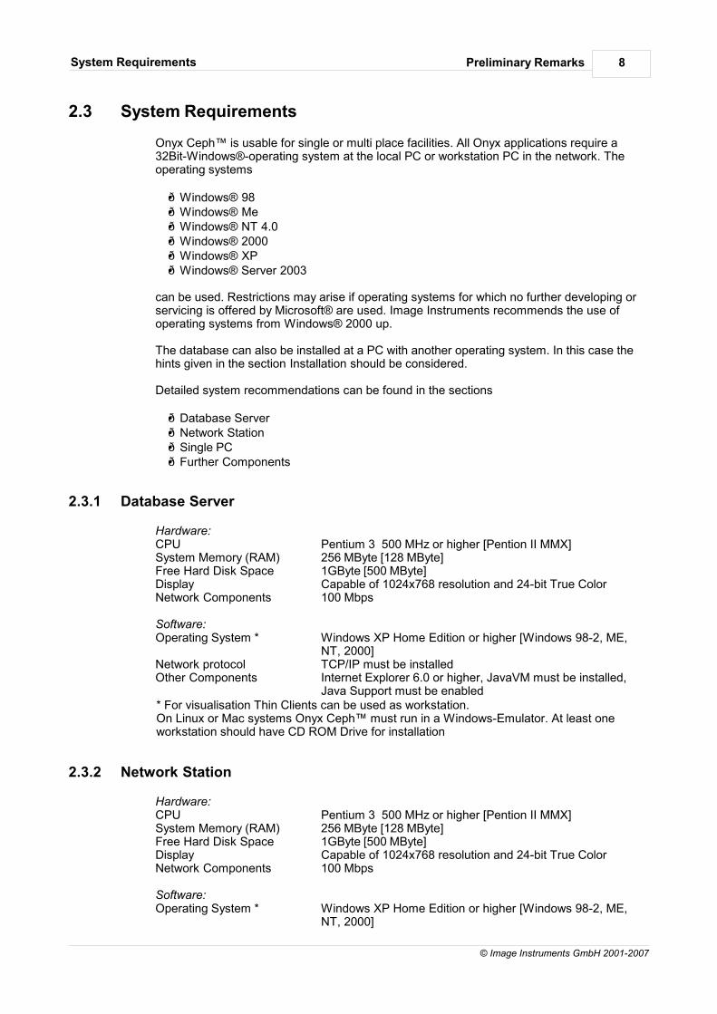
2.3 System Requirements
Onyx Ceph™ is usable for single or multi place facilities. All Onyx applications require a32Bit-Windows®-operating system at the local PC or workstation PC in the network. Theoperating systems
Windows® 98 Windows® Me Windows® NT 4.0 Windows® 2000 Windows® XP Windows® Server 2003
can be used. Restrictions may arise if operating systems for which no further developing orservicing is offered by Microsoft® are used. Image Instruments recommends the use ofoperating systems from Windows® 2000 up.
The database can also be installed at a PC with another operating system. In this case thehints given in the section Installation should be considered.
Detailed system recommendations can be found in the sections
Database Server Network Station Single PC Further Components
2.3.1 Database Server
Hardware:CPU Pentium 3 500 MHz or higher [Pention II MMX]System Memory (RAM) 256 MByte [128 MByte]Free Hard Disk Space 1GByte [500 MByte]Display Capable of 1024x768 resolution and 24-bit True Color Network Components 100 Mbps
Software:Operating System * Windows XP Home Edition or higher [Windows 98-2, ME,
NT, 2000]Network protocol TCP/IP must be installedOther Components Internet Explorer 6.0 or higher, JavaVM must be installed,
Java Support must be enabled* For visualisation Thin Clients can be used as workstation. On Linux or Mac systems Onyx Ceph™ must run in a Windows-Emulator. At least oneworkstation should have CD ROM Drive for installation
2.3.2 Network Station
Hardware:CPU Pentium 3 500 MHz or higher [Pention II MMX]System Memory (RAM) 256 MByte [128 MByte]Free Hard Disk Space 1GByte [500 MByte]Display Capable of 1024x768 resolution and 24-bit True Color Network Components 100 Mbps
Software:Operating System * Windows XP Home Edition or higher [Windows 98-2, ME,
NT, 2000]
Preliminary RemarksSystem Requirements 9
© Image Instruments GmbH 2001-2007
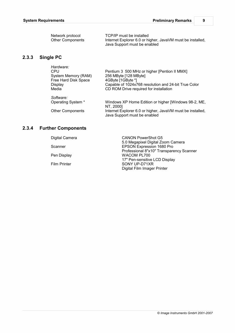
Network protocol TCP/IP must be installedOther Components Internet Explorer 6.0 or higher, JavaVM must be installed,
Java Support must be enabled
2.3.3 Single PC
Hardware:CPU Pentium 3 500 MHz or higher [Pention II MMX]System Memory (RAM) 256 MByte [128 MByte]Free Hard Disk Space 4GByte [1GByte *]Display Capable of 1024x768 resolution and 24-bit True Color Media CD ROM Drive required for installation
Software:Operating System * Windows XP Home Edition or higher [Windows 98-2, ME,
NT, 2000]Other Components Internet Explorer 6.0 or higher, JavaVM must be installed,
Java Support must be enabled
2.3.4 Further Components
Digital Camera CANON PowerShot G5 5.0 Megapixel Digital Zoom Camera
Scanner EPSON Expression 1680 ProProfessional 8"x10" Transparency Scanner
Pen Display WACOM PL700 17" Pen-sensitive LCD Display
Film Printer SONY UP-D71XR Digital Film Imager Printer
Preliminary RemarksInstallation 10
© Image Instruments GmbH 2001-2007
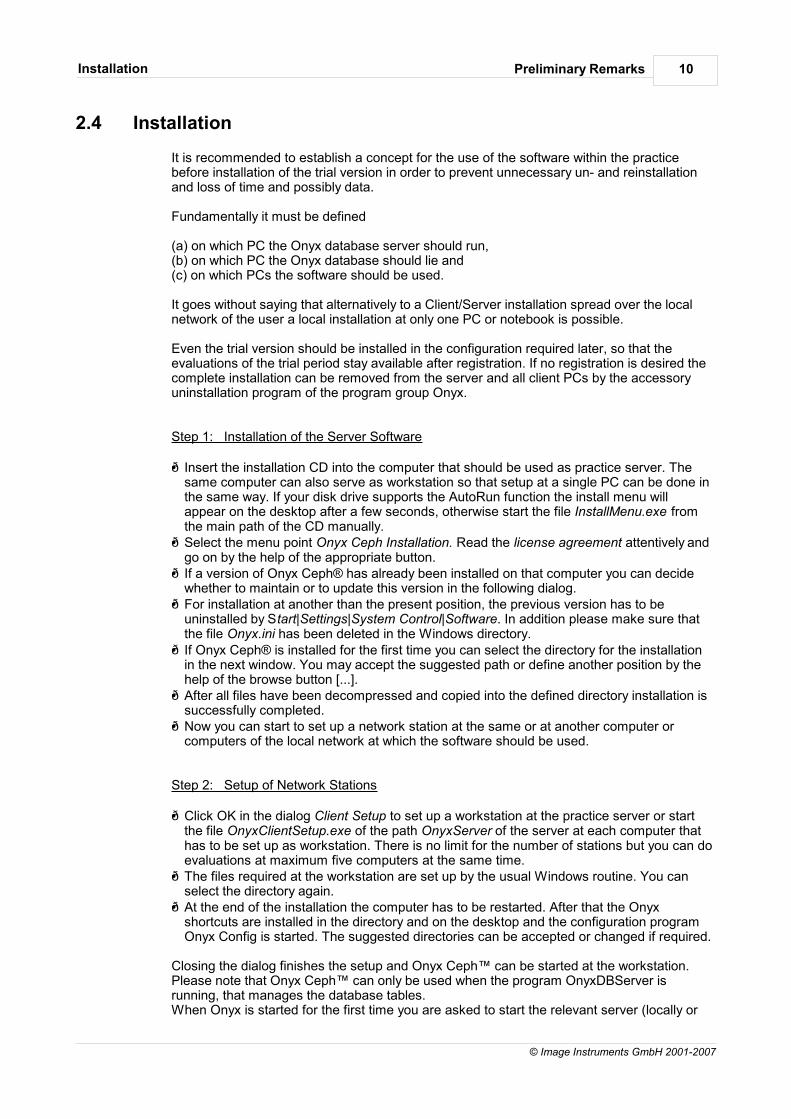
2.4 Installation
It is recommended to establish a concept for the use of the software within the practicebefore installation of the trial version in order to prevent unnecessary un- and reinstallationand loss of time and possibly data.
Fundamentally it must be defined
(a) on which PC the Onyx database server should run, (b) on which PC the Onyx database should lie and (c) on which PCs the software should be used.
It goes without saying that alternatively to a Client/Server installation spread over the localnetwork of the user a local installation at only one PC or notebook is possible.
Even the trial version should be installed in the configuration required later, so that theevaluations of the trial period stay available after registration. If no registration is desired thecomplete installation can be removed from the server and all client PCs by the accessoryuninstallation program of the program group Onyx.
Step 1: Installation of the Server Software
Insert the installation CD into the computer that should be used as practice server. Thesame computer can also serve as workstation so that setup at a single PC can be done inthe same way. If your disk drive supports the AutoRun function the install menu willappear on the desktop after a few seconds, otherwise start the file InstallMenu.exe fromthe main path of the CD manually. Select the menu point Onyx Ceph Installation. Read the license agreement attentively and
go on by the help of the appropriate button. If a version of Onyx Ceph® has already been installed on that computer you can decide
whether to maintain or to update this version in the following dialog. For installation at another than the present position, the previous version has to be
uninstalled by Start|Settings|System Control|Software. In addition please make sure thatthe file Onyx.ini has been deleted in the Windows directory. If Onyx Ceph® is installed for the first time you can select the directory for the installation
in the next window. You may accept the suggested path or define another position by thehelp of the browse button [...]. After all files have been decompressed and copied into the defined directory installation is
successfully completed. Now you can start to set up a network station at the same or at another computer or
computers of the local network at which the software should be used.
Step 2: Setup of Network Stations
Click OK in the dialog Client Setup to set up a workstation at the practice server or startthe file OnyxClientSetup.exe of the path OnyxServer of the server at each computer thathas to be set up as workstation. There is no limit for the number of stations but you can doevaluations at maximum five computers at the same time. The files required at the workstation are set up by the usual Windows routine. You can
select the directory again. At the end of the installation the computer has to be restarted. After that the Onyx
shortcuts are installed in the directory and on the desktop and the configuration programOnyx Config is started. The suggested directories can be accepted or changed if required.
Closing the dialog finishes the setup and Onyx Ceph™ can be started at the workstation.Please note that Onyx Ceph™ can only be used when the program OnyxDBServer isrunning, that manages the database tables. When Onyx is started for the first time you are asked to start the relevant server (locally or

Preliminary RemarksInstallation 11
© Image Instruments GmbH 2001-2007
LAN). The registration is done relating to the server program OnyxDBServer. The use ofOnyx Ceph™ as registered version therefore requires a connection to the registered server.These settings may also be edited and adjusted after the program start by the menu itemOptions|Onyx Server. That also applies for the available start options of the server program.
Preliminary RemarksLicense Agreement 12
© Image Instruments GmbH 2001-2007
2.5 License Agreement
The commercial use of the software Onyx Ceph™ requires the conclusion of an End UserLicense Agreement. His consent to the agreement the user gives before activating theregistration key.
1. Termination.Either party may terminate this End User License Agreement ("Agreement") at anytime without giving reasons and report effective upon notice. On termination of thatagreement the user has to immediately remove the software and all informationprovided by IMAGE INSTRUMENTS from all his equipment.
2. License.A IMAGE INSTRUMENTS hereby grants the user a nonexclusive, limited license to
use the software according to the terms and conditions of this agreement. B The software may only be used by the user's employees, students or partners
and/or physicians who have privileges at the user's facility, who are trained ortraining in the fields the software is used for ("Authorized Personnel"). However, thesoftware may used for medical diagnoses and treatment planning only by competenthealthcare or dental care professionals who rely on their clinical discretion andjudgement in diagnosis and treatment. The user declares his sole responsibility forensuring the responsible and appropriate use of the software in view of all attendantcircumstances, indications and contraindications.
C The software is licensed for the internal use at the user's facilities only. That meansthe user may not (i) copy, download, upload or in any other way duplicate except for(a) one (1) copy of the software on the hard drive of the authorized hardware and/orone (1) copy of the software for backup purposes only, (b) the copy and/or (c) theprintout of a limited extend of the information provided by the software for internaluse only; (ii) sell, distribute, sublicense or provide access to a third party; (iii)compile or develop further; (iv) use or let use the software for the benefit of thirdparties including holdings and subsidiaries without the express written consent ofIMAGE INSTRUMENTS; (v) de-compile or disassemble any part of the software or(vi) modify remove any proprietary markings or restrictive legends placed on it.
3. Property Rights/Confidentiality.A The user regards the software as a whole and any parts of it as confidential
information ("Confidential Information"). The user may not, nor permit others to,provide, disclose or otherwise make such Confidential Information available to, oraccessible by, any person other than Authorized Personnel.
B The user shall take appropriate security precautions to effect his obligations acc. tosection 3(A). The software, the copyrights thereupon and the trademarks utilized inconnection therewith are and shall remain the sole property of IMAGEINSTRUMENTS.
4. Warranties/Disclaimer.A IMAGE INSTRUMENTS warrants that the information contained in the software has
been obtained from what it believes are reliable sources. However, except as statedabove in this agreement the software is provided "AS IT IS" and NO ASSURANCEOR WARRANTY; EXPRESS OR IMPLIED; IS MADE REGARDING THESOFTWARE, INCLUDING, WITHOUT LIMITATION; ANY WARRANTIES FORAPPLICABILITY OR FITNESS FOR A PARTICULAR PURPOSE. NO WARRANTYIS MADE THAT THE SOFTWARE WILL PERFORM WITHOUT INTERRUPTIONOR FREE FROM ERRORS.
B In no event IMAGE INSTRUMENTS or any distributor of IMAGE INSTRUMENTS isliable for any direct, indirect, incidental, special or consequential damages arisingfrom or caused by the use of, reliance on or inability to access and use anyinformation contained in the software, even if the user has been previously advisedof the possibility of such damages or losses.
5. Survivability.Not withstanding the expiration or termination of this Agreement for any reason

Preliminary RemarksLicense Agreement 13
© Image Instruments GmbH 2001-2007
whatsoever, the provisions of sections 3 and 4 shall survive and bind the partiesindefinitely.

Preliminary RemarksRegistration 14
© Image Instruments GmbH 2001-2007
2.6 Registration
The restrictions occurring in the trial mode may be abolished by registration of theinstallation at the developer's.
The registration dialog can be started by the menu point Options|Onyx Registration or theitem Programs|Onyx|OnyxRegister that can be reached via the Windows® Start button.For registration Onyx Ceph™ has to be closed at all workstations.
Step 1:Fill out all fields of the registration dialog and go to Step 2.Please not that the practice name is cAsE-SeNsItIvE and that filling out the colored fields isobligatory.
Step 2:Check the registration data again and save it by the help of the buttons "Save as File >>>" or"Copy to Clipboard >>>". Transmit the content of the file or the clipboard by email or phone
by email: [email protected] by phone: +49 371 9093140
After that you receive the key to release the software in Step 3.
Step 3:Load or type the registration key. Capitalization is not necessary. After having read andaccepted the End User License Agreement click the button "Register".
Hint:In addition to the release of his installation in the network of the practice or clinic theregistered user can get a second key for each license in order to use the program at alocally distant workstation (notebook or PC at home), too. This registration provided onrequest is restricted to one workstation whereas the LAN installation can be installed at anarbitrary number of PCs in the network and simultaneously used at up to 5 stations.
If the secondary release is required in the relevant registration dialog the same practicename as for the primary release must be used.Synchronized data exchange between both installations is possible by the Exchangefunction.
Preliminary RemarksInterfaces 15
© Image Instruments GmbH 2001-2007
2.7 Interfaces
Onyx Ceph™ supports interfaces to third programs such as practice management systems(PMS), image recording and management systems, digital X-ray systems or other programsoffered by further sellers.
For bidirectional data exchange with practice management programs beside an internalPMS interface the VDDSinterface can be used. Both versions are free.Both interfaces aim at he possibility of handing over the patient data from the managementprogram directly to Onyx Ceph™ in order to setup a new patient record or open an alreadyexisting record. at the same time handing over should start or activate the program.Returning of specific evaluation results to the program calling is optional.From Version 2.7 up the internal PMS interface by an ActiveX component also supports theconfigurable visualization of the patient's images in the management program.
Data exchange with image acquisition and image management programs of digital X-raysystems is supported for the devices of all relevant manufacturers in the orthodontic sector.The relevant configurations have to be set in the dialog of the menu item Options|DigitalX-ray. Detailed explanations about that topic are available in the technical documentation.
Preliminary RemarksDocumentation 16
© Image Instruments GmbH 2001-2007
2.8 Documentation
For documentation to Onyx Ceph™ the manuals
Program Help Technical Help Quick Start and Lexicon
are available as online help in HTMLhelp format as well as in printing. All manuals can becalled by the menu point Help or by the Help buttons in the dialogs.
The Program Help comprises descriptions of the functions of Onyx Ceph™ and the Supplementary Programs according to the menu structure.
The Technical Help comprises information about the Installation and the setting up of theInterfaces to third programs.
In the Quick Start Help, in contrast to the Program Help, the use of Onyx Ceph™ isdescribed according to the usual work routine in Diagnostics and Treatment planning and bymeans of a concrete example case.
In addition the Lexicon provides a professional reference book with detailed explanations toall installed analyzing methods and references to source material.
Preliminary RemarksSoftware Support 17
© Image Instruments GmbH 2001-2007
2.9 Software Support
Image Instruments endeavours to provide a high quality support in case of questions orproblems arising in connection with the installation and use of Onyx Ceph™ to all usersindependent of the kind of registration selected.
Trial Version:In order to get familiar with the software Onyx Ceph™ it can be used for up to 50 evaluationsat 10 patients in an unlicensed trial mode free of charge. Commercial use of the trial versionis not allowed. Registration of the trial version can be done via internet.
For users of the unregistered trial version extensive information and explanations can becalled at www.onyx-ceph.de. In the menu point Support of the website a form for onlinedispatch of queries is available. The answers will be sent to the email address of the sender.The queries will be processed according to the capacity available.Even during the trial period it is possible to update the unregistered trial installation to thecurrent version in order to judge the entire functionality.
Registered Versions:The license versions OSL (Open Subscription License) and RL+ (Runtime License plusSupport) contain the option Software Service. That, in addition to the extend describedabove, comprises
dispatch of a new installation CD with the current program version when the license isrenewed (Update) and after error removal (Patch)
use of the product hotline Onyx Ceph™ via email ([email protected]) or the clientarea of the internet homepage www.onyx-ceph.de. The required user login is dispatchedtogether with the registration data.
Preliminary RemarksSupplementary Programs 18
© Image Instruments GmbH 2001-2007
2.10 Supplementary Programs
Together with the application Onyx Ceph™ during the installation procedure a number ofsupplementary programs and help files are installed in the program group Onyx. Theseprograms provide an extended functionality and can be executed independently of the mainprogram by the Start button of the Windows® task bar and the item Programs|Onyx|... ateach Onyx Ceph™ workstation:
Onyx Admin Onyx Backup Onyx Config Onyx DB Server Onyx Patch Onyx Register Onyx Uninstall Onyx Update Onyx View Onyx Stat Onyx PVL
Onyx Stat and Onyx PVL do not belong to the standard packet Onyx Ceph™, but can beprovided especially for methodically working staff in practices and clinics on the basis of aseparate contractual arrangement.
2.10.1 Onyx Admin
The program Onyx Admin offers the opportunity to activate the User Administration and toassign access rights for the work with Onyx Ceph™ to each user or to each group of users.Activation of the administration tool is especially advisable within larger practices or clinics inorder to coordinate the access to patient or finding data by more than one user. If the user administration is activated creating and editing of findings is only possible afterentering of the correct password and within the scope of the access privileges assigned tothe logged-in user
2.10.2 Onyx Backup
The program Onyx Backup is stored in the program group Onyx during installation of OnyxCeph™.Onyx Backup permits the manual backup of different components of the system OnyxCeph™ for the purposes of data storage or restoration of the state of these componentssaved as backup. Selection of the components to be saved and starting the backup is done in the tab sheetData Storage. Saving of patient related data is configured in the panels Database and Original Images.Analogous to the backup reloading of saved data is configured in the tab sheet DataRestoration .According to the data volume the creation of the backup copy can take several minutes upto hours as every single file is zipped and copied to the data medium. A backup of the patient data (without the original images) takes places before every softwareupdate.
2.10.3 Onyx Config
The program Onyx Config permits setting valid for the entire system or for the specificworkstation. Beside language version and image formats these are settings to directories forstorage of global and local data mainly.
Preliminary RemarksSupplementary Programs 19
© Image Instruments GmbH 2001-2007
In addition in the tab sheet Tools different functions for maintenance and error removal or forcreation of protocol files are available.
2.10.4 Onyx DB Server
From Version 2.7 Onyx Ceph™ uses a Client/Server database for internal dataadministration. Therefore the program Onyx DB Server must be running on the networkserver in order to answer the incoming requests.
2.10.5 Onyx Patch
The program Onyx Patch permits the installation of program supplementations such asindividual analyses, printing forms or gallery layouts. The manufacturer provides the patchesas files which can be loaded and executed in Onyx Patch.
2.10.6 Onyx Register
The program Onyx Register can be used for registration as commercial user of OnyxCeph™. Without registration maximal up to 50 findings for maximal 10 patients can beestablished in Onyx Ceph™ for trial purposes. Merely data exchange and printing functionsare restricted.Start Onyx Register by the menu point Options|Onyx Registration. Fill in the colored fields inStep 1 and check the entries in Step 2. Copy or save these data by the help of the availablebuttons and send them to the given address by email. Alternatively you can phone theregistration data, of course. In Step 3 the software key can be loaded as file, inserted from the clipboard or manuallytyped into the relevant fields.
2.10.7 Onyx Uninstall
Onyx Uninstall can be used to uninstall an Onyx Ceph™ Installation at a workstation or atthe server.All relevant files and paths of the selected installation that are only used by Onyx Ceph™ areremoved. In case of an uninstallation at the server all data and images saved in OnyxCeph™ will irretrievably get lost.Directories and files that are in use during uninstallation must be manually deleted later.
2.10.8 Onyx Update
Users of the license versions OSL (Open Subscription License) or RL+ (Runtime License +Support) are offered the opportunity to keep their application up to date. This update ispossible online or offline. For executing the update Onyx Ceph™ has to be closed at allworkstations.
When is a new update available?Updates ere provided to supplement new functions or remove errors. Accordingly there arerecommended and necessary updates. All users are informed about necessary updates byan email to the stated address. Recommended updates are only announced in the internet.Compare the version number of your current installation stated in the menu point Help|AboutOnyx with the version number of the Version currently available in the internet atwww.onyx-ceph.de regularly.
Online Update:In case of an internet connection being available at one of the Onyx Ceph™ workstationsthe Online Update can be called by the menu point Options|Onyx Update or by the item Programs|Onyx|OnyxUpdate that can be called by Windows® Start button. After that an FTP
Preliminary RemarksSupplementary Programs 20
© Image Instruments GmbH 2001-2007
connection to the Onyx Update server is established and the user's Server Installation ischecked. A hint appears stating which files should be updated. It is possible to exclude theupdate of the extensive online help files, which may be useful in case of a low data transferrate. After starting the download all files to be updated in the Onyx server directory areoverwritten by files from the FTP Server. Alternatively the Online Update can be directly called at the website www.onyx-ceph.de byclicking on the update icon with the current version number.After the Online Update the updated application is available at all workstations.
Offline Update:In case of a current Onyx Ceph™ Installation CD being available it can be inserted at one ofthe Onyx Ceph™ workstations. Since this PC is recognized as Onyx Ceph™ client computerafter selection of the language version as first menu item the item "Update Onyx Server" isoffered in the Splash menu. After starting the download all files to be updated in the Onyx server directory are overwrittenby files from the CD. After the Offline Update the updated application is available at all workstations.
Hint:For reasons of time before the Online Update no Auto-Backup is executed. If saving of thecurrent state is desired, the backup must be manually started by the program Onyx Backupin the program group Onyx before the update. In case of a failed update the original datacan be restored by Onyx Backup.
In order to judge the entire functionality during the trial period it is also possible to update theinstallation to the current version in the trial mode.
2.10.9 Onyx View
The patient-related photo album Onyx View™ beside patient allocation and classification ofall digital images in the practice ensures the use of various images processing -, display -and search functions and the direct link to the appropriate evaluation program.Even for images that can not be evaluated in Onyx Ceph™ characteristics can be defined sothat they can be used for statistic calculations.In addition to the images available in the Onyx Ceph™ database all images of the patientthat are stored in the databases of linked third programs or in unequivocally identifiable pathstructures can be displayed and managed in Onyx View™.
2.10.10 Onyx Stat
Onyx Stat represents a standalone statistical module that allows to perform improvedstatistical evaluations within the Onyx findings database. Statistical projects can base on anyclient database, thus the findings to be statistically evaluated can come from several clinicsor practices. Onyx Stat does not belong to the standard packet Onyx Ceph™ but can be provided inparticular for scientific studies on the basis of a separate contractual agreement.
2.10.11 Onyx PVL
For creation and modification of the analyses implemented in Onyx Ceph™ the developmenttool Onyx PVL is used. By the help of this finding editor creation and implementation ofindividual analyzing methods is possible.It also permits definition of individual diagnostic methods that use not yet implementedimage types or combinations of several methods (e.g. cephalometry lateral and frontal).Onyx PVL does not belong to the standard packet Onyx Ceph™ but can be provided inparticular for methodically working personnel in practices or clinics on the basis of aseparate contractual agreement.

Preliminary RemarksSupplementary Programs 21
© Image Instruments GmbH 2001-2007
Alternatively, the implementation of individual findings is offered as service. In such casesplease contact the manufacturer or use the form provided on the Onyx Ceph™- homepageof the internet.
Functionality
Functionality 23
© Image Instruments GmbH 2001-2007
3 Functionality
The Windows™ -Software Onyx Ceph™ provides tools simply and flexibly to use for theduties
Visual Diagnostics Treatment Planning Case Documentation Presentation Communication and Training and Education
in orthodontics and orthognathic surgery in order to achieve a higher treatment quality and amore effective course of treatment. Via configurable interfaces for practice managementsoftware and digital image sources Onyx Ceph™ can be easily integrated into the practiceenvironment. Onyx Ceph™ can be installed in the practice network as Client/Server application and madeavailable at each workstation. The same way a mobile working method and the use in locallydistant networks is supported.
In addition to the local network capability a specific client structure enables online or offlinedispatch of findings to colleagues or services enterprises within the virtual Onyx network andimport of the results after evaluation as well as electronic finding exchange with healthinsurance companies, experts, colleagues or following physicians.Moreover a multitude of import and export functions allows data exchange with relevantthird.

FunctionalityHint 24
© Image Instruments GmbH 2001-2007
3.1 Hint
All measurement -, simulation - and image processing tools available in Onyx Ceph™merely serve to assist you in finding a diagnosis. All diagnoses and possible treatmentsmust be based on clinical knowledge and experience. Onyx Ceph™ does not lay claim toreplacing the diagnosis of the physician.
Furthermore we would like to point out that the results obtained by the measuring functionsof Onyx Ceph™ can only be correctly calculated on condition of the object to be evaluatedbeing digitally imaged in the focal plane without distortion.This has to be secured by means of appropriate calibration of the image acquisition processor suitable correction of the digitally recorded images.
FunctionalityVisual Diagnostics 25
© Image Instruments GmbH 2001-2007
3.2 Visual Diagnostics
By the help of Onyx Ceph™ all images relevant for finding the diagnose (clinicalphotographs, intraoral photographs, X-rays, photographs of the dental casts, ...) can bepatient-relatedly loaded, edited, classified, managed, evaluated and presented. The visual-diagnostic evaluation comprises the use of the available analyzing methods(Standard Analyses, Individual Analyses) for the relevant image type.
Beside the measurement function available for all image types, by means of which lines,angles, ratios and projections can be calculated within a set of 4 landmarks, for the imagetypes
Photostat Lateral Photostat Frontal Photostat Smiling Cephalogram Lateral Cephalogram Frontal Orthopantomogram Hand X-ray Cast Deciduous Dentition Cast Mixed Dentition Cast Permanent Dentition
specific orthodontic analyzing methods are implemented. In addition by the help of thefinding editor Onyx PVL individual user analyses can be defined.
3.2.1 Photostat Lateral
The following analyses are implemented in Onyx Ceph™ at present. Descriptions of theseveral analyses are available in the Lexicon of Results.
Lip Analysis Profile Analysis acc. to A.M. Schwarz Profile Analysis acc. to Legan and Burstone Proportional Analysis Analysis acc. to the University of Tübingen Analysis acc. to the University of Berlin Soft Tissue Analysis acc. to Epker und Fish Soft Tissue Profile Analysis acc. to Rakosi Measurements
3.2.2 Photostat Frontal
The following analyses are implemented in Onyx Ceph™ at present. Descriptions of theseveral analyses are available in the Lexicon of Results.
Divine Proportion Symmety Analysis acc. to the University of Tübingen Analysis acc. to the University of Berlin Measurements

FunctionalityVisual Diagnostics 26
© Image Instruments GmbH 2001-2007
3.2.3 Photostat Smiling
The following analyses are implemented in Onyx Ceph™ at present. Descriptions of theseveral analyses are available in the Lexicon of Results.
Golden Ruler Measurements
3.2.4 Cephalogram Lateral
The following analyses are implemented in Onyx Ceph™ at present. Descriptions of theseveral analyses are available in the Lexicon of Results.
Analysis of the Association of Austrian Orthodontists Analysis of the University of Aachen Analysis of the University of Berlin Analysis of the University of Bern Analysis of the University of Bonn Analysis of the University of Frankfurt Analysis of the University of Freiburg Analysis of the University of Heidelberg Analysis of the University of Innsbruck Analysis of the University of Mainz Analysis of the University of Münster Analysis of the University of Oslo Analysis of the University of Tübingen Analysis of the University of Ulm Analysis of the University of Venezuela Analysis acc. to Harvold Analysis acc. to McGann Analysis acc. to McNamara Analysis acc. to Riedel Analysis acc. to Sampermans Bergen-/ Hasund-Analysis Burstone - Craniofacial Analysis Burstone - Soft Tissue Analysis Clark - Correlative Analysis Clark - Linear Craniofacial Analysis Downs Analysis Downs Analysis (international) Dual Plane Analysis Epker & Fish - Soft Tissue Profile Analysis Holdaway - Soft Tissue Analysis ISV acc. to Hollmann/Haberler Jarabak - Dental Analysis Jarabak - Skeletal Analysis Legan & Burstone Lip Analysis Measurements Mc Laughlin Analysis Modified Zurich Analysis Profile Analysis Rakosi – Metric Analysis Rakosi – Sagittal Analysis Rakosi – Incisor Analysis Rakosi – Vertical Analysis
FunctionalityVisual Diagnostics 27
© Image Instruments GmbH 2001-2007
Ricketts – 11-Factors-Short-Analysis Ricketts – Comprehensive Analysis Sassouni - Skeletal Archial Analysis Schmuth - Differential Analysis Schwarz – Gnathometris Analysis Schwarz – Craniometric Analysis Soft Tissue Analysis Steiner Analysis Tweed Triangle
3.2.5 Cephalogram Frontal
The following analyses are implemented in Onyx Ceph™ at present. Descriptions of theseveral analyses are available in the Lexicon of Results.
Analysis acc. to Ricketts Analysis acc. to the University of Münster Measurements
3.2.6 OPT
The following analyses are implemented in Onyx Ceph™ at present. Descriptions of theseveral analyses are available in the Lexicon of Results.
Implant Survey Dental Age acc. to Demirjian Dental Age acc. to the University of Tübingen Measurements
3.2.7 Hand X-ray
The following analyses are implemented in Onyx Ceph™ at present. Descriptions of theseveral analyses are available in the Lexicon of Results.
Growth Analysis Measurements
3.2.8 Cast Deciduous Dentition
The following analyses are implemented in Onyx Ceph™ at present. Descriptions of theseveral analyses are available in the Lexicon of Results.
Tübingen - Primary Teeth Index Measurements
3.2.9 Cast Mixed Dentition
The following analyses are implemented in Onyx Ceph™ at present. Descriptions of theseveral analyses are available in the Lexicon of Results.
Droschl - Correlative Prediction Korkhaus - Arch Analysis Linder & Harth - Arch Analysis
FunctionalityVisual Diagnostics 28
© Image Instruments GmbH 2001-2007
Berendonk - Expected Need of Space Ballard-Wylie - Expected Need of Space Carey - Expected Need of Space Huckaba - Expected Need of Space Moyers - Expected Need of Space Mühlberg - Expected Need of Space Tanaka - Expected Need of Space Tanaka/Müller - Expected Need of Space Platzbilanz nach Weise Pont Index Tonn - Ratio of Incisor's Widths Measurements
3.2.10 Cast Permanent Dentition
The following analyses are implemented in Onyx Ceph™ at present. Descriptions of theseveral analyses are available in the Lexicon of Results.
Mühlberg - Arch Analysis Arch Length Bolton - Anterior Ratio Bolton - Overall Ratio Korkhaus - Arch Analysis Herren - Arcogram Specific Pont-Index Linder & Harth - Arch Analysis Lundström - Segment Analysis Weise - Space Analysis Pont Index Supporting Zone Analysis Symmetry Tonn - Ratio of Incisor's Widths Measurements
FunctionalityTreatment Planning 29
© Image Instruments GmbH 2001-2007
3.3 Treatment Planning
The current version of the software Onyx Ceph™ offers several functions for treatmentplanning. The options
Treatment Simulation Ricketts VTO Superimposition and Juxtaposition
are available in the menu point Extras.
3.3.1 Treatment Simulation
For visual treatment prognoses the images evaluated by different analyses can be handedover to the Treatment Simulation option. By the help of the two-dimensional image orthodontic or surgical treatment procedures, thatcan be described by displacement and rotation of freely definable bony segments in theimage, can be simulated. The result of the simulation is visualized and can be controlled bymeans of numeric specification of displacement and rotation of each area.The definition of the regions for the orthodontic as well as for the surgical treatment issupported by wizards. For the landmarks of the soft tissue contour calculation rules can be applied and edited bythe user that describe their shift as a result of the displacement of bony areas. Forvisualization of the treatment results to be expected the initial finding is morphed accordingto the calculated changes to the profile.
The results of the analysis selected are transformed during the simulation and can be savedas modified finding in the patient's file card to permit the application of further Onyx Ceph™standard functions.
3.3.2 Ricketts VTO
The item Extras|VTO hands over the measured finding to the implemented VTO module,which permits prediction of normal growth of the patient and the expected results of thetreatment in the tracing of the X-ray based on the cephalometric analysis according toRicketts and in addition allows simulation of these changes in the appropriate photograph ofthe patient.The prediction is automatically done to a great extend according to the method described byRicketts. The results of the analysis selected are transformed during the simulation and can be savedas modified finding in the patient's file card to permit the application of further Onyx Ceph™standard functions.
3.3.3 Juxtaposition
The option Juxtaposition permits the comparison of two or more images of the same type.beside a tabular juxtaposition of the results including norm values and deviations accordingto the selected analysis different graphics can be superimposed (e.g. harmony box, tracingsegments).The superimposition of the tracings can be done by means of landmarks or freely definableimage structures (e.g. stable bony structures in X-ray). All images are aligned according tothe first one. For visualization display options such as tracings, templates and landmarkscan be activated and deactivated. Changes can be illustrated by animation.
The results of the analysis selected are transformed during the simulation and can be saved

FunctionalityTreatment Planning 30
© Image Instruments GmbH 2001-2007
as modified finding in the patient's file card to permit the application of further Onyx Ceph™standard functions.
3.3.4 Superimposition
The option Superimposition permits superimposing of two arbitrary findings. The alignmentof the images to be superimposed can be defined by mutual landmarks or freely set points.In addition the segment and transparency of the superimposition can be changed. Theresulting image can be assigned to the patient as new finding. For this the image type of theprimary initial finding is used.
The results of the analysis selected are transformed during the simulation and can be savedas modified finding in the patient's file card to permit the application of further Onyx Ceph™standard functions.
FunctionalityCase Documentation 31
© Image Instruments GmbH 2001-2007
3.4 Case Documentation
For treatment documentation (printed documentation) the printing options
Standard Printing Form Printing or 1:1 Printing
can be used.
3.4.1 Standard Printing
All image findings can be printed in a standard layout independently of their image type. Theprintout for the current finding comprises below a predefined letterhead, that can be editedby the user, the selectable components
Table Tracing (small) Image and Tracing Image Tracing Harmony Box (if available for the analysis) Facial Growth Pattern (if available for the analysis).
From version Version 2.7 up the layout of the table in the result full screen mode can bedefined.
3.4.2 Form Printing
In contrary to the standard printing the menu point Print Form offers the opportunity to calland use forms created by the help of the form editor. Similar to a Gallery print formsrepresent fixed arrangements of defined objects within one or more pages. Beside imagesalso result tables, free tables, static images, text fields and logos can be included. For eachelement a multitude of characteristics can be defined.
When calling a predefined printing form layout according to the assigned characteristics therelevant objects are filled with elements and information of the current session first. In theprinting dialog, however, changing to objects of the same type is possible.
3.4.3 1:1 Printing
The menu option Analysis|Print 100% can be used to print images and the appropriatetracings in original size. Exact scaling of the finding and correct calibration of the printer arerequired.
FunctionalityPresentation 32
© Image Instruments GmbH 2001-2007
3.5 Presentation
For presentation of images and results, e.g. within the scope of informing and consultingpatients, the options
Album Full Screen and Gallery
are available.
3.5.1 Album
By the context menu item Maximize over the miniaturized findings this view can be extendedto the entire desktop to get an overview of the images available in the separate sessions. Allavailable context menu functions over one or more selected findings or the miniature viewcan furthermore be used. Returning to the normal view is done by deactivating the itemMaximize in the context menu.
3.5.2 Full Screen
By double click or by the context menu item Full Screen over a slide of the miniaturized viewa full screen view of the selected images can be called. If more than one finding is selected the positions of the images can be changed byDrag&Drop. If only one finding is selected by detail zoom a section of interest can be selected byDrag&Drop. The content of the detail field can be moved by pressed left mouse button.Switching to the next finding is done by a left mouse click in a full screen view.
Hint:As usual in Windows, multiple-choice is possible by pressing the Shift or Ctrl button at thesame time. Returning from the full screen mode is possible by a right mouse click or by the Esc button.
3.5.3 Gallery
Galleries represent predefined fixed arrangements of certain image types. Beside theimplemented standard galleries Onyx_2, Onyx_3 and Onyx_8 the user can define owngalleries by the help of the editor. Beside finding images also static images, text fields, logosand short video clips (max. 50MByte) can be included. For each element a multitude ofcharacteristics can be defined.
When calling a predefined gallery layout according to the assigned characteristics therelevant objects are filled with elements and information of the current session first. By thecontext menu, however, changing to objects of the same type but other sessions is possible.Zooming and aligning of an image within the predefined frame is also possible in the gallerylayout. In this way clinical photographs that are arranged side by side can be adjusted withregard to head size or eye level. The Full Screen functionality including detail zoom is alsoavailable.Prepared gallery layouts can be saved and called for presentations within the scope oftreatment discussion and patient education.
FunctionalityCommunication 33
© Image Instruments GmbH 2001-2007
3.6 Communication
For effective data exchange with colleagues and locally distant workstations or thirdprograms the functions
Exchange Export Report and Messages,
that are partly suitable for online use, are available in the menu point Communication. In addition many results (tracings, tables, charts) can be directly exported out of printpreview, gallery or other program windows or can be handed over to other Windows®applications by the clipboard or by Drag&Drop.
3.6.1 Exchange
The option Exchange permits the synchronized exchange (Import/Export) of findings for oneore more patients between different Onyx Ceph™ - databases. That may be data exchangebetween several installations of one user (network and outwork station) or between differentOnyx Ceph™ - users.Beside the diagnostic results finding data can contain appropriate images, attributes, softtissue regulations, simulation results and further additional information. Finding data of other users (clients) is administered in a separate patient file that is alsoused for communication with this partner. Statistic analyses and clinical studies can beapplied to the findings of all as well as to the findings of selected partners.
3.6.2 Export
Finding results can be saved in Excel, Text, Clipboard, HTML and Java format for their usein third programs.
3.6.3 Report
The option Report permits creation of Case-Reports containing findings of one or morepatients, that can be opened and used by the help of an internet browser (e.g. InternetExplorer). By a Java-Applet in the browser several visual functions (zoom; show/hidelandmarks, tracing or templates; display of tables and charts) can be applied.
Hint:The Java-Applet requires the installation and release of the Java-VM functions in theInternet Options of the browser.
3.6.4 Messages
All Onyx Ceph™ workstations of the network can send and receive written information bythe menu option Communication.
FunctionalityTraining and Education 34
© Image Instruments GmbH 2001-2007
3.7 Training and Education
For effective use of Onyx Ceph™ as standard application for digital cephalometrics or fortraining and education different additional options to be used free of charge were developed.
3.7.1 Lexicon
The Lexicon of results provides an overview of all implemented analyzing methods andoffers verbal and graphic explanations to landmarks and results.Beside this dictionary information about landmarks and results is available in thecontext-sensitive help by a right mouse click on the respective field of the list of landmarksor the list of results.
3.7.2 Training Client
Especially for the purposes of university education or training programs that involve work onconcrete examples a so-called training client can be created. That client contains thenecessary exemplary patients and enables evaluation of their findings by a free trial versionproviding all functions of the program. Setting up of own patients and evaluation of theirfindings is not possible in the training client, but switching between training client and trialclient or registered client, respectively, is possible at any time.
3.7.3 Babylon Glossary
Glossaries in German and English language, that can be used with the online translation toolBabylon, allow easy and quick translation of the terminology used in Onyx Ceph™ andfurthermore provide a lot of additional orthodontic expressions and their definitions in Englishand German language.The Babylon-Glossaries can be downloaded for offline-use for free or subscribed foronline-use by the menu point Glossaries [path Health|Medicine|Dentistry] atwww.babylon.com.
Menu bar
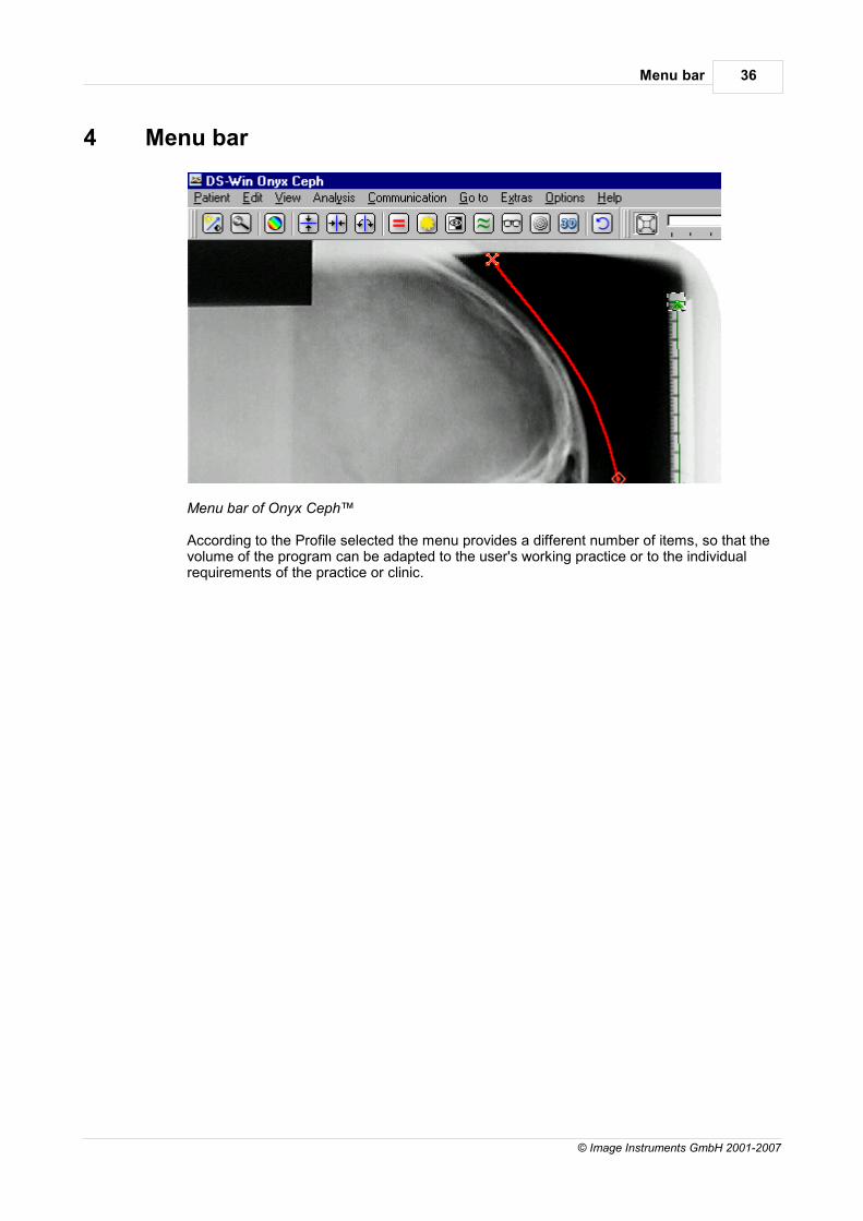
Menu bar 36
© Image Instruments GmbH 2001-2007
4 Menu bar
Menu bar of Onyx Ceph™
According to the Profile selected the menu provides a different number of items, so that thevolume of the program can be adapted to the user's working practice or to the individualrequirements of the practice or clinic.
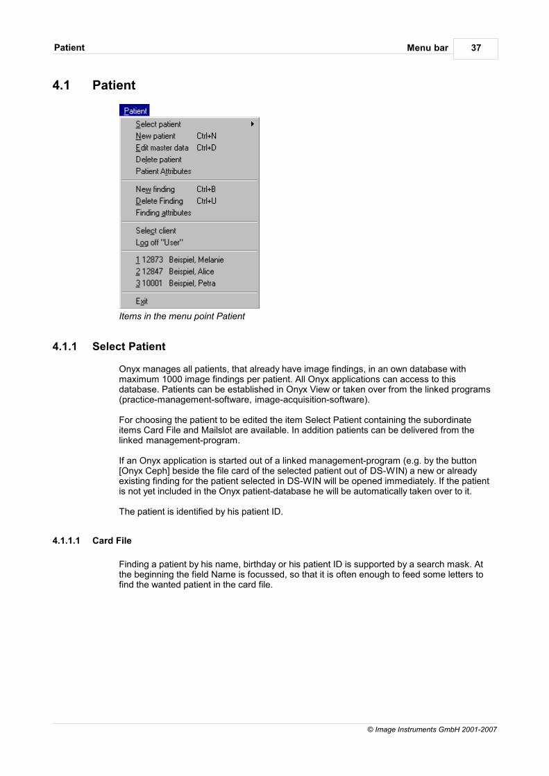
Menu barPatient 37
© Image Instruments GmbH 2001-2007
4.1 Patient
Items in the menu point Patient
4.1.1 Select Patient
Onyx manages all patients, that already have image findings, in an own database withmaximum 1000 image findings per patient. All Onyx applications can access to thisdatabase. Patients can be established in Onyx View or taken over from the linked programs(practice-management-software, image-acquisition-software).
For choosing the patient to be edited the item Select Patient containing the subordinateitems Card File and Mailslot are available. In addition patients can be delivered from thelinked management-program.
If an Onyx application is started out of a linked management-program (e.g. by the button[Onyx Ceph] beside the file card of the selected patient out of DS-WIN) a new or alreadyexisting finding for the patient selected in DS-WIN will be opened immediately. If the patientis not yet included in the Onyx patient-database he will be automatically taken over to it.
The patient is identified by his patient ID.
4.1.1.1 Card File
Finding a patient by his name, birthday or his patient ID is supported by a search mask. Atthe beginning the field Name is focussed, so that it is often enough to feed some letters tofind the wanted patient in the card file.
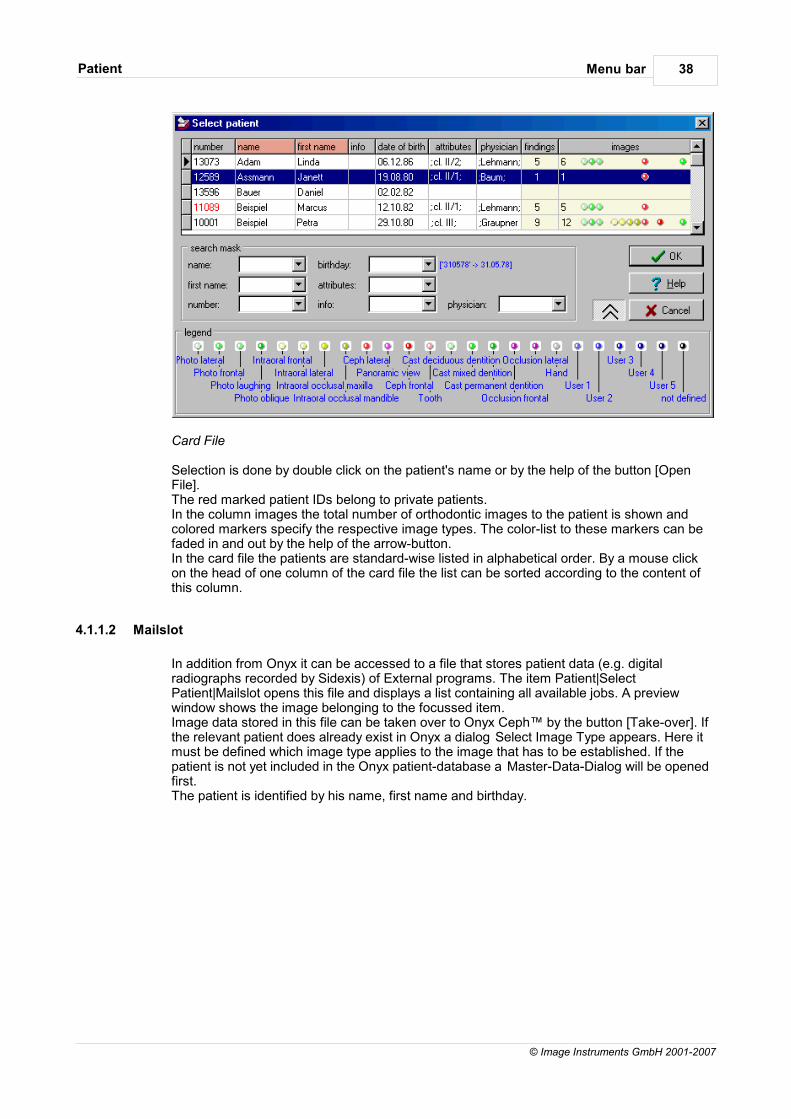
Menu barPatient 38
© Image Instruments GmbH 2001-2007
Card File
Selection is done by double click on the patient's name or by the help of the button [OpenFile].The red marked patient IDs belong to private patients.In the column images the total number of orthodontic images to the patient is shown andcolored markers specify the respective image types. The color-list to these markers can befaded in and out by the help of the arrow-button.In the card file the patients are standard-wise listed in alphabetical order. By a mouse clickon the head of one column of the card file the list can be sorted according to the content ofthis column.
4.1.1.2 Mailslot
In addition from Onyx it can be accessed to a file that stores patient data (e.g. digitalradiographs recorded by Sidexis) of External programs. The item Patient|SelectPatient|Mailslot opens this file and displays a list containing all available jobs. A previewwindow shows the image belonging to the focussed item.Image data stored in this file can be taken over to Onyx Ceph™ by the button [Take-over]. Ifthe relevant patient does already exist in Onyx a dialog Select Image Type appears. Here itmust be defined which image type applies to the image that has to be established. If thepatient is not yet included in the Onyx patient-database a Master-Data-Dialog will be openedfirst.The patient is identified by his name, first name and birthday.
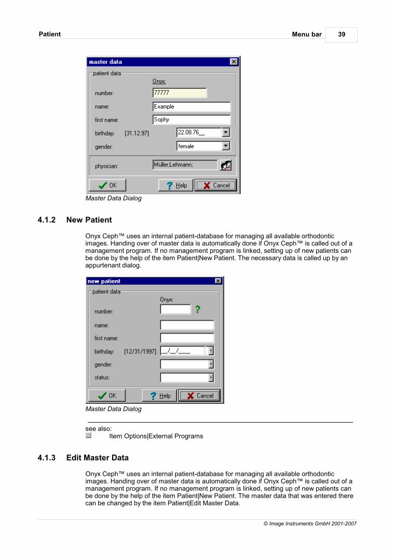
Menu barPatient 39
© Image Instruments GmbH 2001-2007
Master Data Dialog
4.1.2 New Patient
Onyx Ceph™ uses an internal patient-database for managing all available orthodonticimages. Handing over of master data is automatically done if Onyx Ceph™ is called out of amanagement program. If no management program is linked, setting up of new patients canbe done by the help of the item Patient|New Patient. The necessary data is called up by anappurtenant dialog.
Master Data Dialog
see also:Item Options|External Programs
4.1.3 Edit Master Data
Onyx Ceph™ uses an internal patient-database for managing all available orthodonticimages. Handing over of master data is automatically done if Onyx Ceph™ is called out of amanagement program. If no management program is linked, setting up of new patients canbe done by the help of the item Patient|New Patient. The master data that was entered therecan be changed by the item Patient|Edit Master Data.
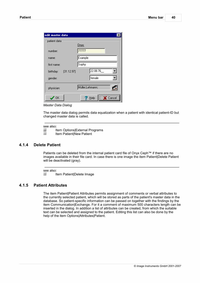
Menu barPatient 40
© Image Instruments GmbH 2001-2007
Master Data Dialog
The master data dialog permits data equalization when a patient with identical patient-ID butchanged master data is called.
see also:Item Options|External ProgramsItem Patient|New Patient
4.1.4 Delete Patient
Patients can be deleted from the internal patient card file of Onyx Ceph™ if there are noimages available in their file card. In case there is one image the item Patient|Delete Patientwill be deactivated (gray).
see also:Item Patient|Delete Image
4.1.5 Patient Attributes
The item Patient|Patient Attributes permits assignment of comments or verbal attributes tothe currently selected patient, which will be stored as parts of the patient's master data in thedatabase. So patient-specific information can be passed on together with the findings by theitem Communication|Exchange. For it a comment of maximum 500 characters length can beinserted in the dialog. In addition a list of attributes can be created, from which the suitabletext can be selected and assigned to the patient. Editing this list can also be done by thehelp of the item Options|Attributes|Patient.
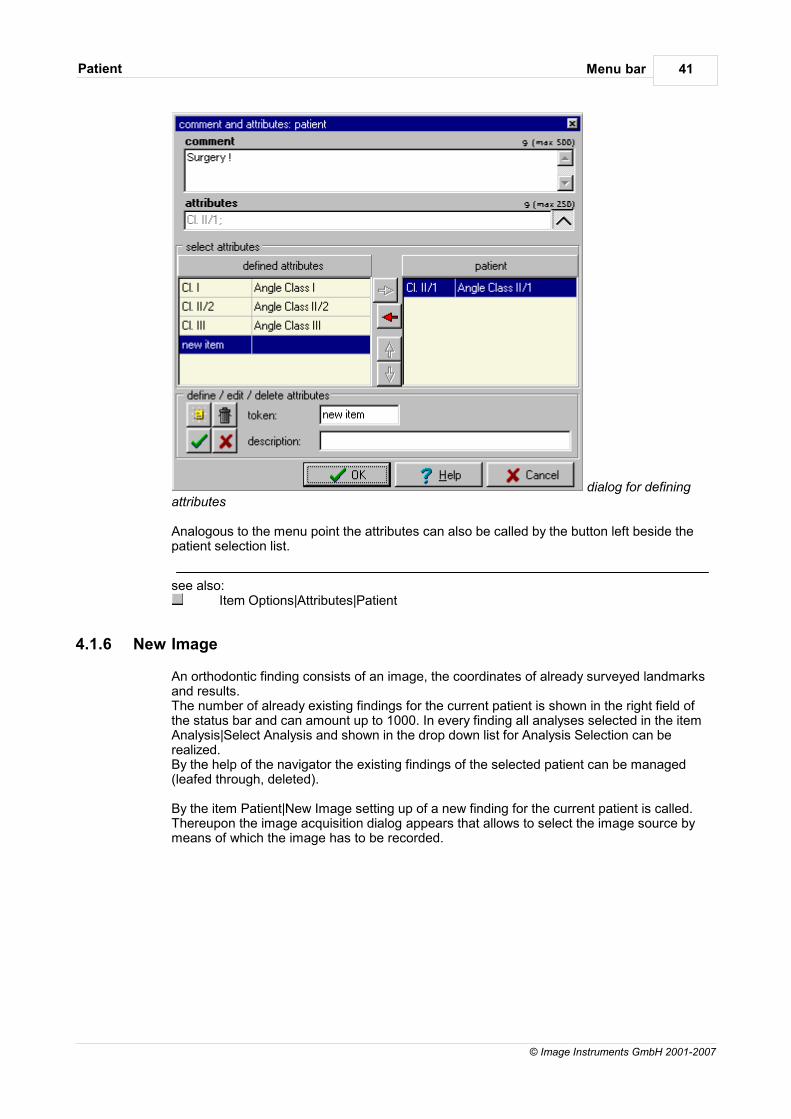
Menu barPatient 41
© Image Instruments GmbH 2001-2007
dialog for definingattributes
Analogous to the menu point the attributes can also be called by the button left beside thepatient selection list.
see also:Item Options|Attributes|Patient
4.1.6 New Image
An orthodontic finding consists of an image, the coordinates of already surveyed landmarksand results.The number of already existing findings for the current patient is shown in the right field ofthe status bar and can amount up to 1000. In every finding all analyses selected in the itemAnalysis|Select Analysis and shown in the drop down list for Analysis Selection can berealized.By the help of the navigator the existing findings of the selected patient can be managed(leafed through, deleted).
By the item Patient|New Image setting up of a new finding for the current patient is called.Thereupon the image acquisition dialog appears that allows to select the image source bymeans of which the image has to be recorded.
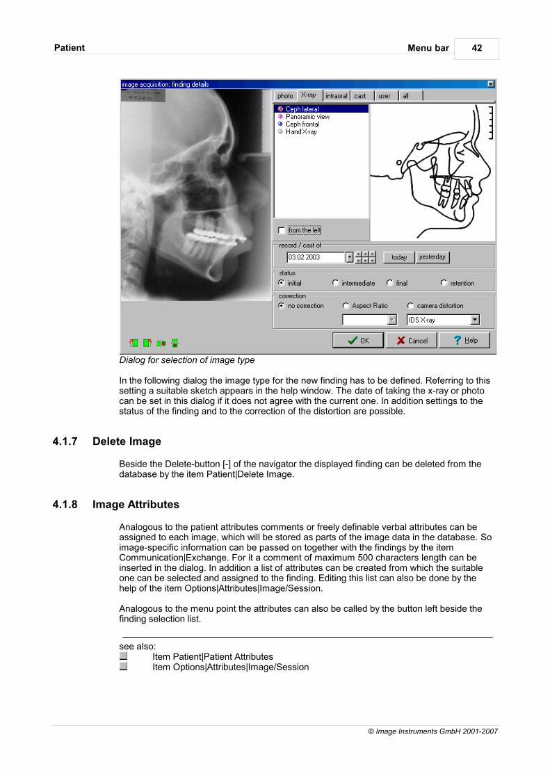
Menu barPatient 42
© Image Instruments GmbH 2001-2007
Dialog for selection of image type In the following dialog the image type for the new finding has to be defined. Referring to thissetting a suitable sketch appears in the help window. The date of taking the x-ray or photocan be set in this dialog if it does not agree with the current one. In addition settings to thestatus of the finding and to the correction of the distortion are possible.
4.1.7 Delete Image
Beside the Delete-button [-] of the navigator the displayed finding can be deleted from thedatabase by the item Patient|Delete Image.
4.1.8 Image Attributes
Analogous to the patient attributes comments or freely definable verbal attributes can beassigned to each image, which will be stored as parts of the image data in the database. Soimage-specific information can be passed on together with the findings by the itemCommunication|Exchange. For it a comment of maximum 500 characters length can beinserted in the dialog. In addition a list of attributes can be created from which the suitableone can be selected and assigned to the finding. Editing this list can also be done by thehelp of the item Options|Attributes|Image/Session.
Analogous to the menu point the attributes can also be called by the button left beside thefinding selection list.
see also:Item Patient|Patient AttributesItem Options|Attributes|Image/Session
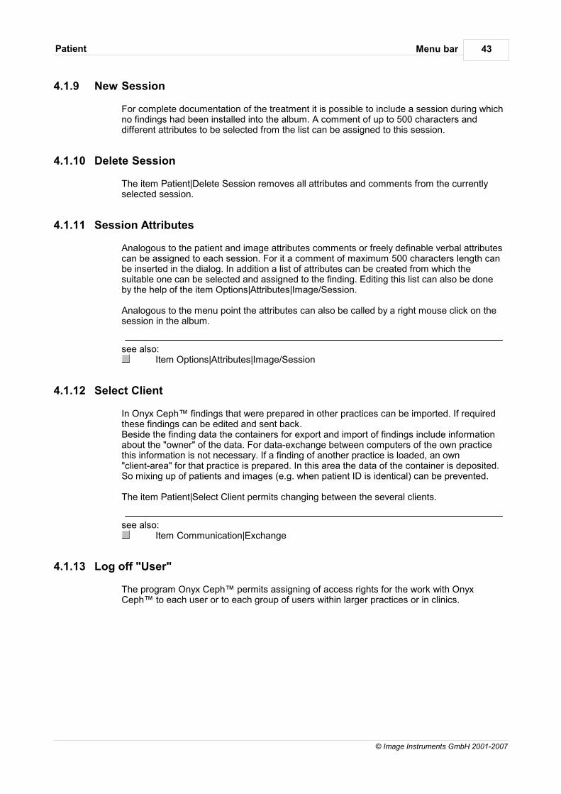
Menu barPatient 43
© Image Instruments GmbH 2001-2007
4.1.9 New Session
For complete documentation of the treatment it is possible to include a session during whichno findings had been installed into the album. A comment of up to 500 characters anddifferent attributes to be selected from the list can be assigned to this session.
4.1.10 Delete Session
The item Patient|Delete Session removes all attributes and comments from the currentlyselected session.
4.1.11 Session Attributes
Analogous to the patient and image attributes comments or freely definable verbal attributescan be assigned to each session. For it a comment of maximum 500 characters length canbe inserted in the dialog. In addition a list of attributes can be created from which thesuitable one can be selected and assigned to the finding. Editing this list can also be doneby the help of the item Options|Attributes|Image/Session.
Analogous to the menu point the attributes can also be called by a right mouse click on thesession in the album.
see also:Item Options|Attributes|Image/Session
4.1.12 Select Client
In Onyx Ceph™ findings that were prepared in other practices can be imported. If requiredthese findings can be edited and sent back. Beside the finding data the containers for export and import of findings include informationabout the "owner" of the data. For data-exchange between computers of the own practicethis information is not necessary. If a finding of another practice is loaded, an own"client-area" for that practice is prepared. In this area the data of the container is deposited.So mixing up of patients and images (e.g. when patient ID is identical) can be prevented.
The item Patient|Select Client permits changing between the several clients.
see also:Item Communication|Exchange
4.1.13 Log off "User"
The program Onyx Ceph™ permits assigning of access rights for the work with OnyxCeph™ to each user or to each group of users within larger practices or in clinics.
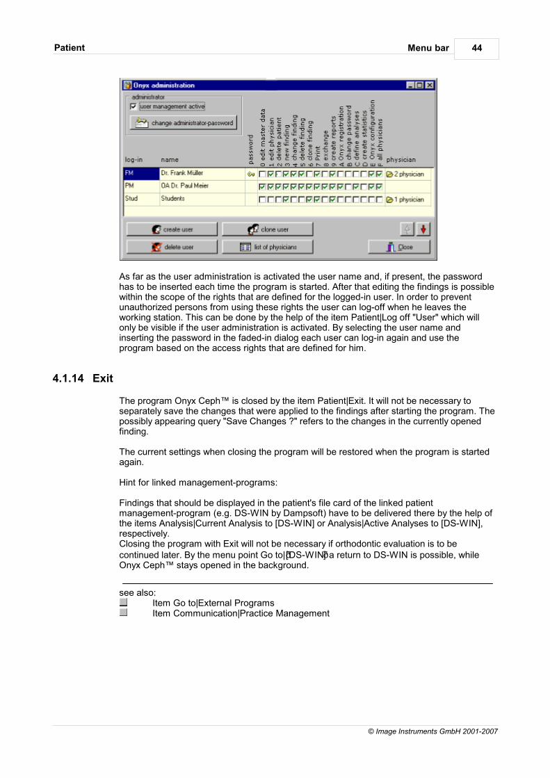
Menu barPatient 44
© Image Instruments GmbH 2001-2007
As far as the user administration is activated the user name and, if present, the passwordhas to be inserted each time the program is started. After that editing the findings is possiblewithin the scope of the rights that are defined for the logged-in user. In order to preventunauthorized persons from using these rights the user can log-off when he leaves theworking station. This can be done by the help of the item Patient|Log off "User" which willonly be visible if the user administration is activated. By selecting the user name andinserting the password in the faded-in dialog each user can log-in again and use theprogram based on the access rights that are defined for him.
4.1.14 Exit
The program Onyx Ceph™ is closed by the item Patient|Exit. It will not be necessary toseparately save the changes that were applied to the findings after starting the program. Thepossibly appearing query "Save Changes ?" refers to the changes in the currently openedfinding.
The current settings when closing the program will be restored when the program is startedagain.
Hint for linked management-programs:
Findings that should be displayed in the patient's file card of the linked patientmanagement-program (e.g. DS-WIN by Dampsoft) have to be delivered there by the help ofthe items Analysis|Current Analysis to [DS-WIN] or Analysis|Active Analyses to [DS-WIN],respectively.Closing the program with Exit will not be necessary if orthodontic evaluation is to becontinued later. By the menu point Go to|DS-WIN a return to DS-WIN is possible, whileOnyx Ceph™ stays opened in the background.
see also:Item Go to|External ProgramsItem Communication|Practice Management
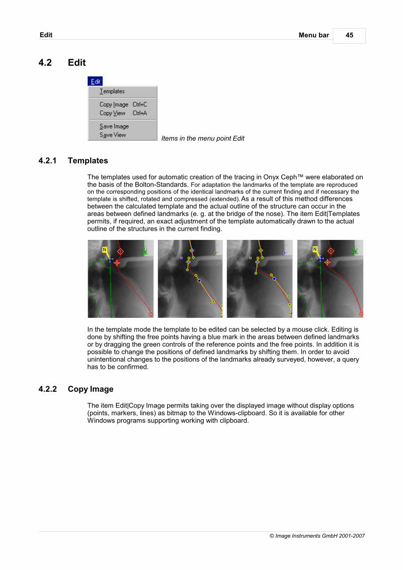
Menu barEdit 45
© Image Instruments GmbH 2001-2007
4.2 Edit
Items in the menu point Edit
4.2.1 Templates
The templates used for automatic creation of the tracing in Onyx Ceph™ were elaborated onthe basis of the Bolton-Standards. For adaptation the landmarks of the template are reproducedon the corresponding positions of the identical landmarks of the current finding and if necessary thetemplate is shifted, rotated and compressed (extended). As a result of this method differencesbetween the calculated template and the actual outline of the structure can occur in theareas between defined landmarks (e. g. at the bridge of the nose). The item Edit|Templatespermits, if required, an exact adjustment of the template automatically drawn to the actualoutline of the structures in the current finding.
In the template mode the template to be edited can be selected by a mouse click. Editing isdone by shifting the free points having a blue mark in the areas between defined landmarksor by dragging the green controls of the reference points and the free points. In addition it ispossible to change the positions of defined landmarks by shifting them. In order to avoidunintentional changes to the positions of the landmarks already surveyed, however, a queryhas to be confirmed.
4.2.2 Copy Image
The item Edit|Copy Image permits taking over the displayed image without display options(points, markers, lines) as bitmap to the Windows-clipboard. So it is available for otherWindows programs supporting working with clipboard.
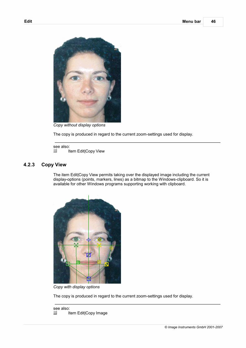
Menu barEdit 46
© Image Instruments GmbH 2001-2007
Copy without display options
The copy is produced in regard to the current zoom-settings used for display.
see also:Item Edit|Copy View
4.2.3 Copy View
The item Edit|Copy View permits taking over the displayed image including the currentdisplay-options (points, markers, lines) as a bitmap to the Windows-clipboard. So it isavailable for other Windows programs supporting working with clipboard.
Copy with display options
The copy is produced in regard to the current zoom-settings used for display.
see also:Item Edit|Copy Image
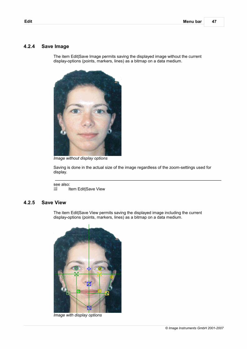
Menu barEdit 47
© Image Instruments GmbH 2001-2007
4.2.4 Save Image
The item Edit|Save Image permits saving the displayed image without the currentdisplay-options (points, markers, lines) as a bitmap on a data medium.
Image without display options
Saving is done in the actual size of the image regardless of the zoom-settings used fordisplay.
see also:Item Edit|Save View
4.2.5 Save View
The item Edit|Save View permits saving the displayed image including the currentdisplay-options (points, markers, lines) as a bitmap on a data medium.
Image with display options

Menu barEdit 48
© Image Instruments GmbH 2001-2007
Saving is done in the actual size of the image regardless of the zoom-settings used fordisplay.
see also:Item Edit|Save Image
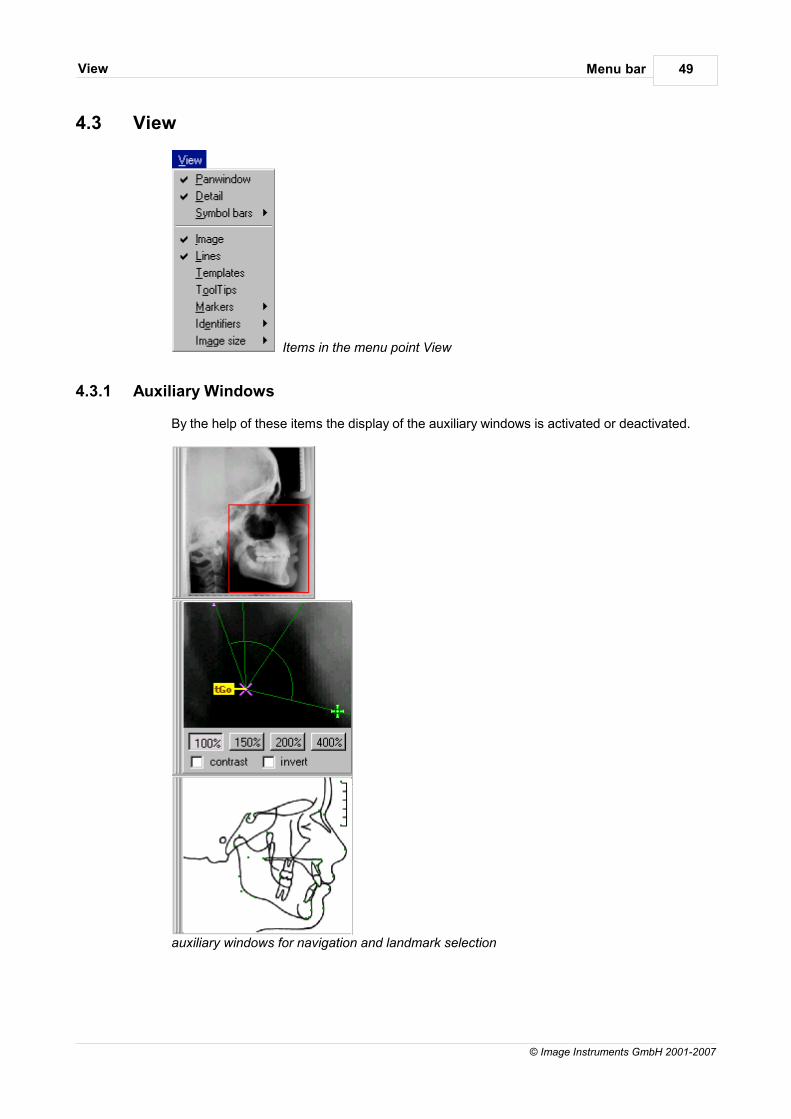
Menu barView 49
© Image Instruments GmbH 2001-2007
4.3 View
Items in the menu point View
4.3.1 Auxiliary Windows
By the help of these items the display of the auxiliary windows is activated or deactivated.
auxiliary windows for navigation and landmark selection
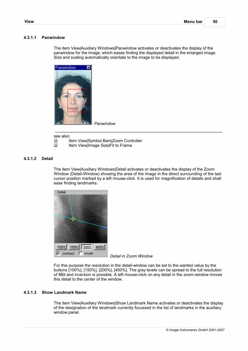
Menu barView 50
© Image Instruments GmbH 2001-2007
4.3.1.1 Panwindow
The item View|Auxiliary Windows|Panwindow activates or deactivates the display of thepanwindow for the image, which eases finding the displayed detail in the enlarged image.Size and scaling automatically orientate to the image to be displayed.
Panwindow
see also:Item View|Symbol Bars|Zoom ControllerItem View|Image Size|Fit to Frame
4.3.1.2 Detail
The item View|Auxiliary Windows|Detail activates or deactivates the display of the ZoomWindow (Detail-Window) showing the area of the image in the direct surrounding of the lastcursor position marked by a left mouse-click. It is used for magnification of details and shallease finding landmarks.
Detail in Zoom Window
For this purpose the resolution in the detail-window can be set to the wanted value by thebuttons [100%], [150%], [200%], [400%]. The gray levels can be spread to the full resolutionof 8Bit and inversion is possible. A left mouse-click on any detail in the zoom-window movesthis detail to the center of the window.
4.3.1.3 Show Landmark Name
The item View|Auxiliary Windows|Show Landmark Name activates or deactivates the displayof the designation of the landmark currently focussed in the list of landmarks in the auxiliarywindow panel.
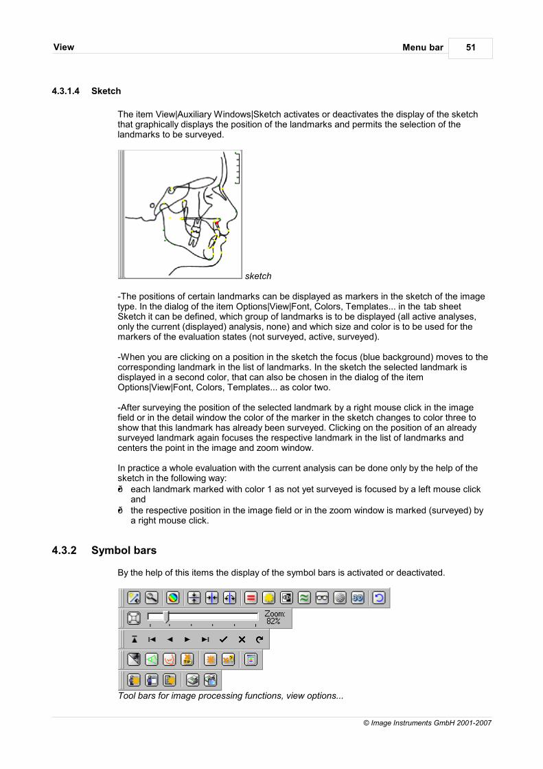
Menu barView 51
© Image Instruments GmbH 2001-2007
4.3.1.4 Sketch
The item View|Auxiliary Windows|Sketch activates or deactivates the display of the sketchthat graphically displays the position of the landmarks and permits the selection of thelandmarks to be surveyed.
sketch
-The positions of certain landmarks can be displayed as markers in the sketch of the imagetype. In the dialog of the item Options|View|Font, Colors, Templates... in the tab sheetSketch it can be defined, which group of landmarks is to be displayed (all active analyses,only the current (displayed) analysis, none) and which size and color is to be used for themarkers of the evaluation states (not surveyed, active, surveyed).
-When you are clicking on a position in the sketch the focus (blue background) moves to thecorresponding landmark in the list of landmarks. In the sketch the selected landmark isdisplayed in a second color, that can also be chosen in the dialog of the itemOptions|View|Font, Colors, Templates... as color two.
-After surveying the position of the selected landmark by a right mouse click in the imagefield or in the detail window the color of the marker in the sketch changes to color three toshow that this landmark has already been surveyed. Clicking on the position of an alreadysurveyed landmark again focuses the respective landmark in the list of landmarks andcenters the point in the image and zoom window.
In practice a whole evaluation with the current analysis can be done only by the help of thesketch in the following way: each landmark marked with color 1 as not yet surveyed is focused by a left mouse click
and the respective position in the image field or in the zoom window is marked (surveyed) by
a right mouse click.
4.3.2 Symbol bars
By the help of this items the display of the symbol bars is activated or deactivated.
Tool bars for image processing functions, view options...
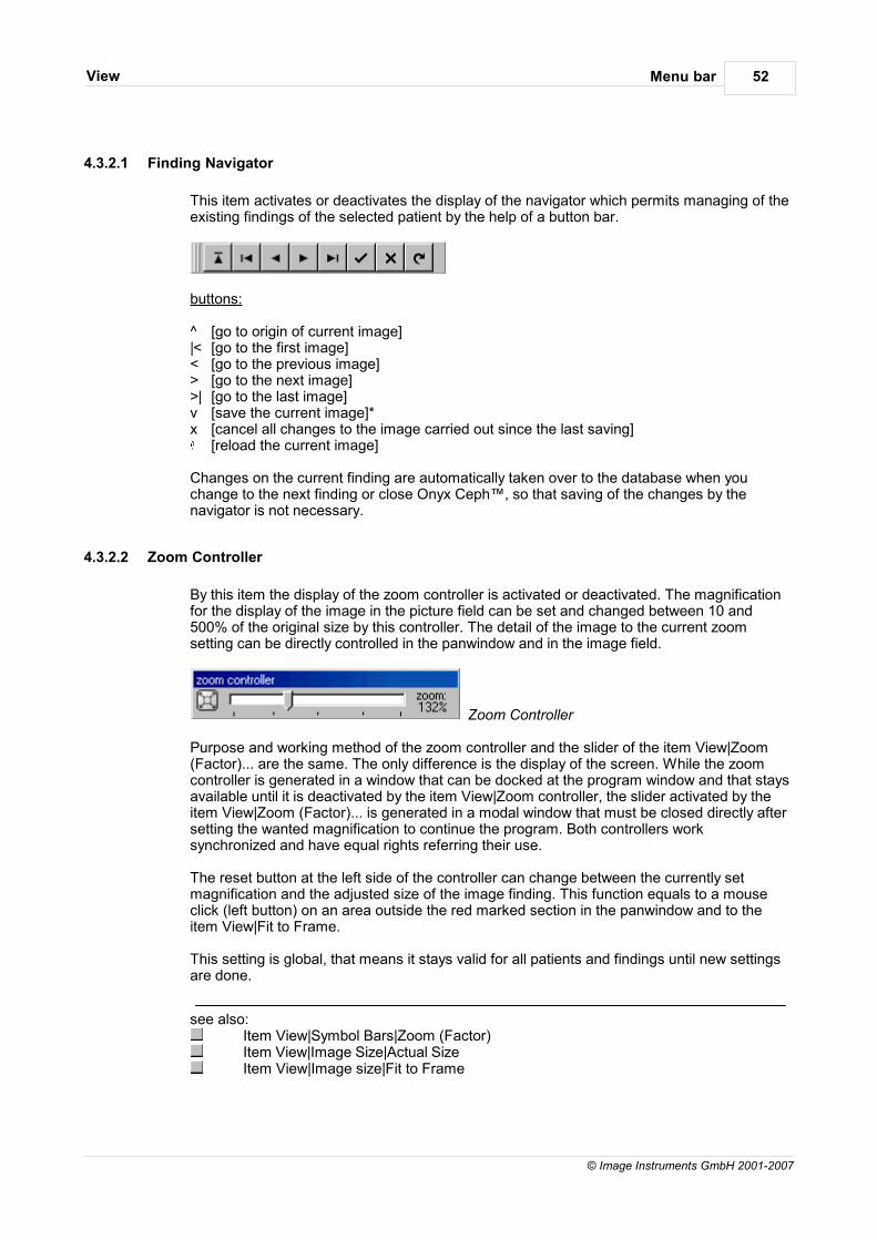
Menu barView 52
© Image Instruments GmbH 2001-2007
4.3.2.1 Finding Navigator
This item activates or deactivates the display of the navigator which permits managing of theexisting findings of the selected patient by the help of a button bar.
buttons:
^ [go to origin of current image]|< [go to the first image]< [go to the previous image]> [go to the next image]>| [go to the last image]v [save the current image]*x [cancel all changes to the image carried out since the last saving]
[reload the current image]
Changes on the current finding are automatically taken over to the database when youchange to the next finding or close Onyx Ceph™, so that saving of the changes by thenavigator is not necessary.
4.3.2.2 Zoom Controller
By this item the display of the zoom controller is activated or deactivated. The magnificationfor the display of the image in the picture field can be set and changed between 10 and500% of the original size by this controller. The detail of the image to the current zoomsetting can be directly controlled in the panwindow and in the image field.
Zoom Controller
Purpose and working method of the zoom controller and the slider of the item View|Zoom(Factor)... are the same. The only difference is the display of the screen. While the zoomcontroller is generated in a window that can be docked at the program window and that staysavailable until it is deactivated by the item View|Zoom controller, the slider activated by theitem View|Zoom (Factor)... is generated in a modal window that must be closed directly aftersetting the wanted magnification to continue the program. Both controllers worksynchronized and have equal rights referring their use.
The reset button at the left side of the controller can change between the currently setmagnification and the adjusted size of the image finding. This function equals to a mouseclick (left button) on an area outside the red marked section in the panwindow and to theitem View|Fit to Frame.
This setting is global, that means it stays valid for all patients and findings until new settingsare done.
see also:Item View|Symbol Bars|Zoom (Factor)Item View|Image Size|Actual SizeItem View|Image size|Fit to Frame
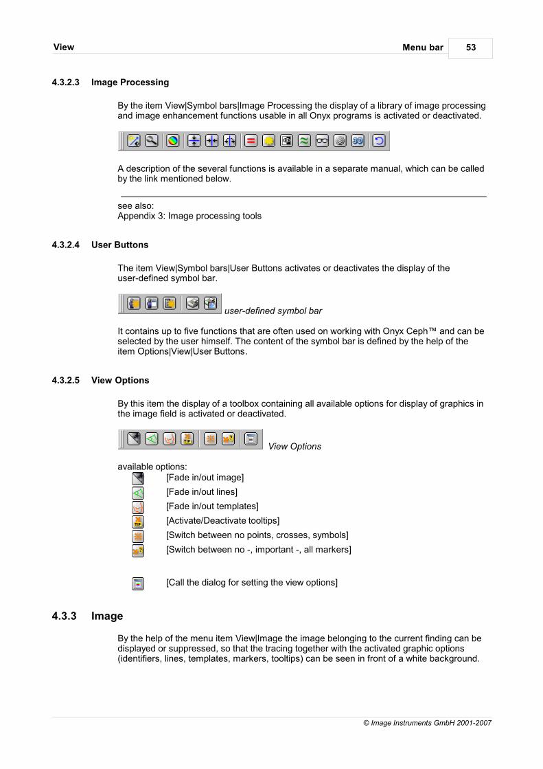
Menu barView 53
© Image Instruments GmbH 2001-2007
4.3.2.3 Image Processing
By the item View|Symbol bars|Image Processing the display of a library of image processingand image enhancement functions usable in all Onyx programs is activated or deactivated.
A description of the several functions is available in a separate manual, which can be calledby the link mentioned below.
see also:Appendix 3: Image processing tools
4.3.2.4 User Buttons
The item View|Symbol bars|User Buttons activates or deactivates the display of theuser-defined symbol bar.
user-defined symbol bar
It contains up to five functions that are often used on working with Onyx Ceph™ and can beselected by the user himself. The content of the symbol bar is defined by the help of theitem Options|View|User Buttons.
4.3.2.5 View Options
By this item the display of a toolbox containing all available options for display of graphics inthe image field is activated or deactivated.
View Options
available options:[Fade in/out image]
[Fade in/out lines]
[Fade in/out templates]
[Activate/Deactivate tooltips]
[Switch between no points, crosses, symbols]
[Switch between no -, important -, all markers]
[Call the dialog for setting the view options]
4.3.3 Image
By the help of the menu item View|Image the image belonging to the current finding can bedisplayed or suppressed, so that the tracing together with the activated graphic options(identifiers, lines, templates, markers, tooltips) can be seen in front of a white background.
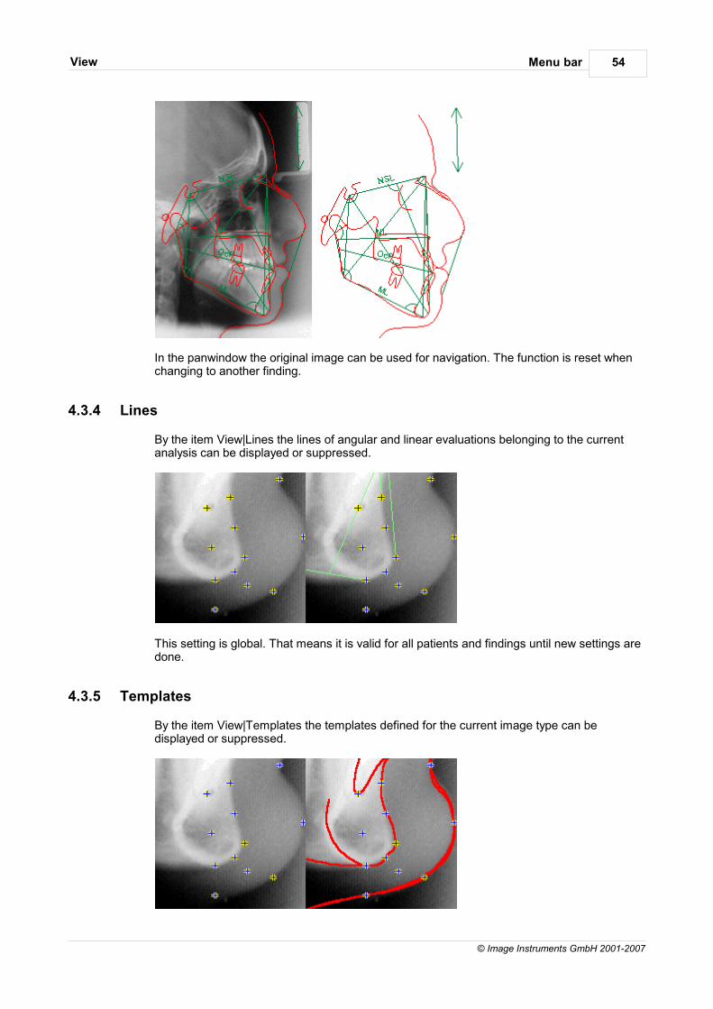
Menu barView 54
© Image Instruments GmbH 2001-2007
In the panwindow the original image can be used for navigation. The function is reset whenchanging to another finding.
4.3.4 Lines
By the item View|Lines the lines of angular and linear evaluations belonging to the currentanalysis can be displayed or suppressed.
This setting is global. That means it is valid for all patients and findings until new settings aredone.
4.3.5 Templates
By the item View|Templates the templates defined for the current image type can bedisplayed or suppressed.
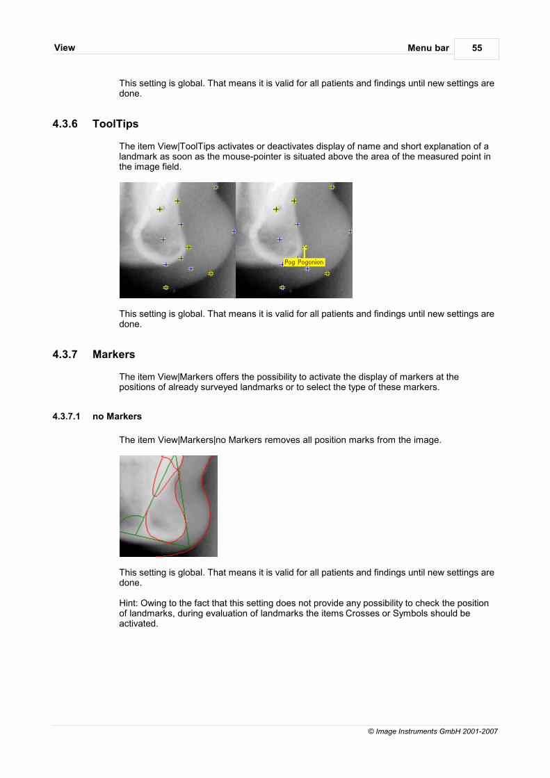
Menu barView 55
© Image Instruments GmbH 2001-2007
This setting is global. That means it is valid for all patients and findings until new settings aredone.
4.3.6 ToolTips
The item View|ToolTips activates or deactivates display of name and short explanation of alandmark as soon as the mouse-pointer is situated above the area of the measured point inthe image field.
This setting is global. That means it is valid for all patients and findings until new settings aredone.
4.3.7 Markers
The item View|Markers offers the possibility to activate the display of markers at thepositions of already surveyed landmarks or to select the type of these markers.
4.3.7.1 no Markers
The item View|Markers|no Markers removes all position marks from the image.
This setting is global. That means it is valid for all patients and findings until new settings aredone.
Hint: Owing to the fact that this setting does not provide any possibility to check the positionof landmarks, during evaluation of landmarks the items Crosses or Symbols should beactivated.
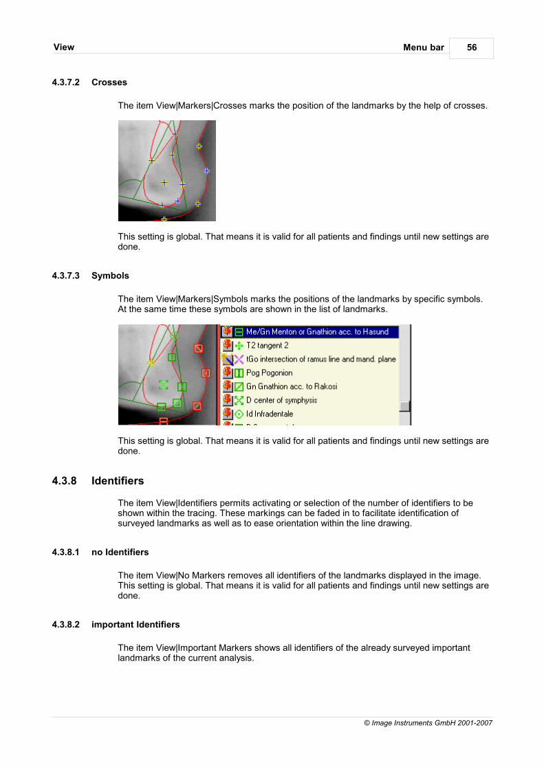
Menu barView 56
© Image Instruments GmbH 2001-2007
4.3.7.2 Crosses
The item View|Markers|Crosses marks the position of the landmarks by the help of crosses.
This setting is global. That means it is valid for all patients and findings until new settings aredone.
4.3.7.3 Symbols
The item View|Markers|Symbols marks the positions of the landmarks by specific symbols.At the same time these symbols are shown in the list of landmarks.
This setting is global. That means it is valid for all patients and findings until new settings aredone.
4.3.8 Identifiers
The item View|Identifiers permits activating or selection of the number of identifiers to beshown within the tracing. These markings can be faded in to facilitate identification ofsurveyed landmarks as well as to ease orientation within the line drawing.
4.3.8.1 no Identifiers
The item View|No Markers removes all identifiers of the landmarks displayed in the image.This setting is global. That means it is valid for all patients and findings until new settings aredone.
4.3.8.2 important Identifiers
The item View|Important Markers shows all identifiers of the already surveyed importantlandmarks of the current analysis.
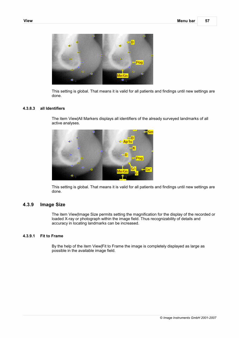
Menu barView 57
© Image Instruments GmbH 2001-2007
This setting is global. That means it is valid for all patients and findings until new settings aredone.
4.3.8.3 all Identifiers
The item View|All Markers displays all identifiers of the already surveyed landmarks of allactive analyses.
This setting is global. That means it is valid for all patients and findings until new settings aredone.
4.3.9 Image Size
The item View|Image Size permits setting the magnification for the display of the recorded orloaded X-ray or photograph within the image field. Thus recognizability of details andaccuracy in locating landmarks can be increased.
4.3.9.1 Fit to Frame
By the help of the item View|Fit to Frame the image is completely displayed as large aspossible in the available image field.
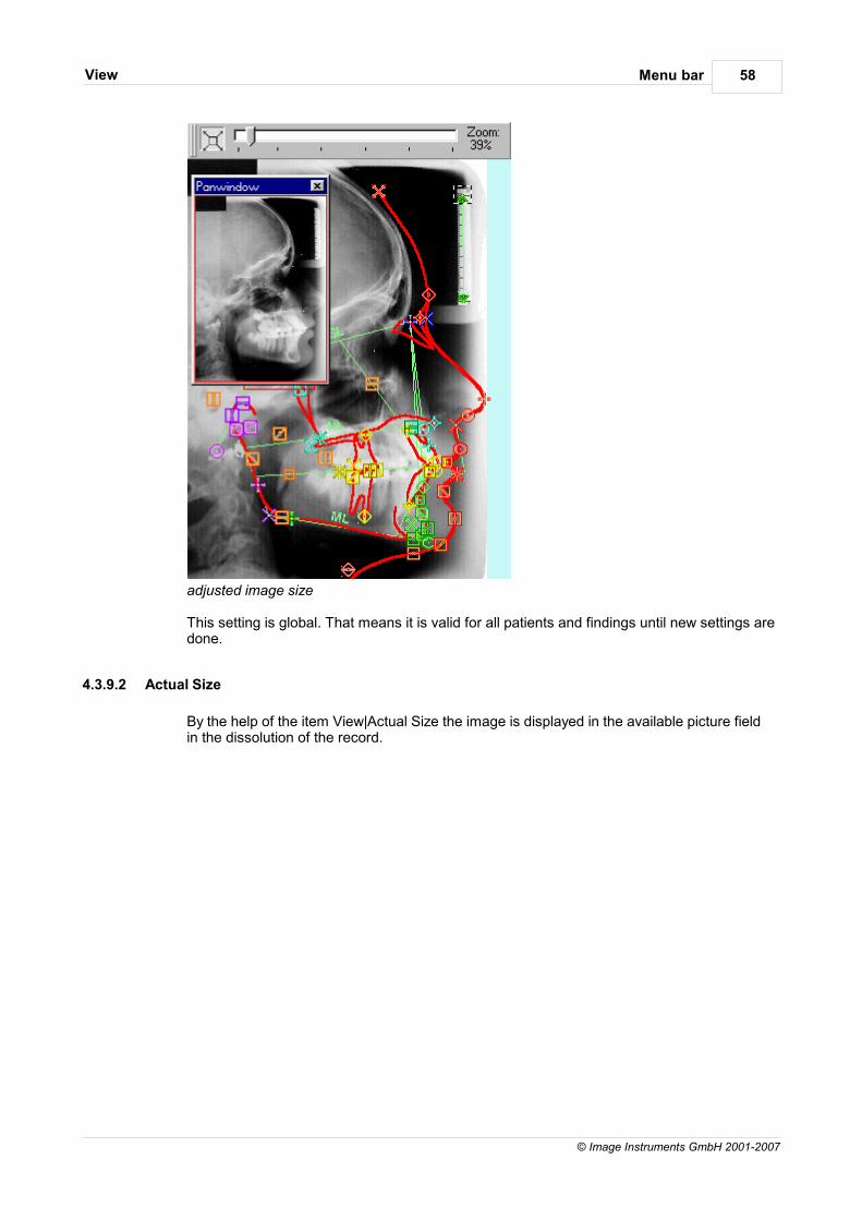
Menu barView 58
© Image Instruments GmbH 2001-2007
adjusted image size
This setting is global. That means it is valid for all patients and findings until new settings aredone.
4.3.9.2 Actual Size
By the help of the item View|Actual Size the image is displayed in the available picture fieldin the dissolution of the record.
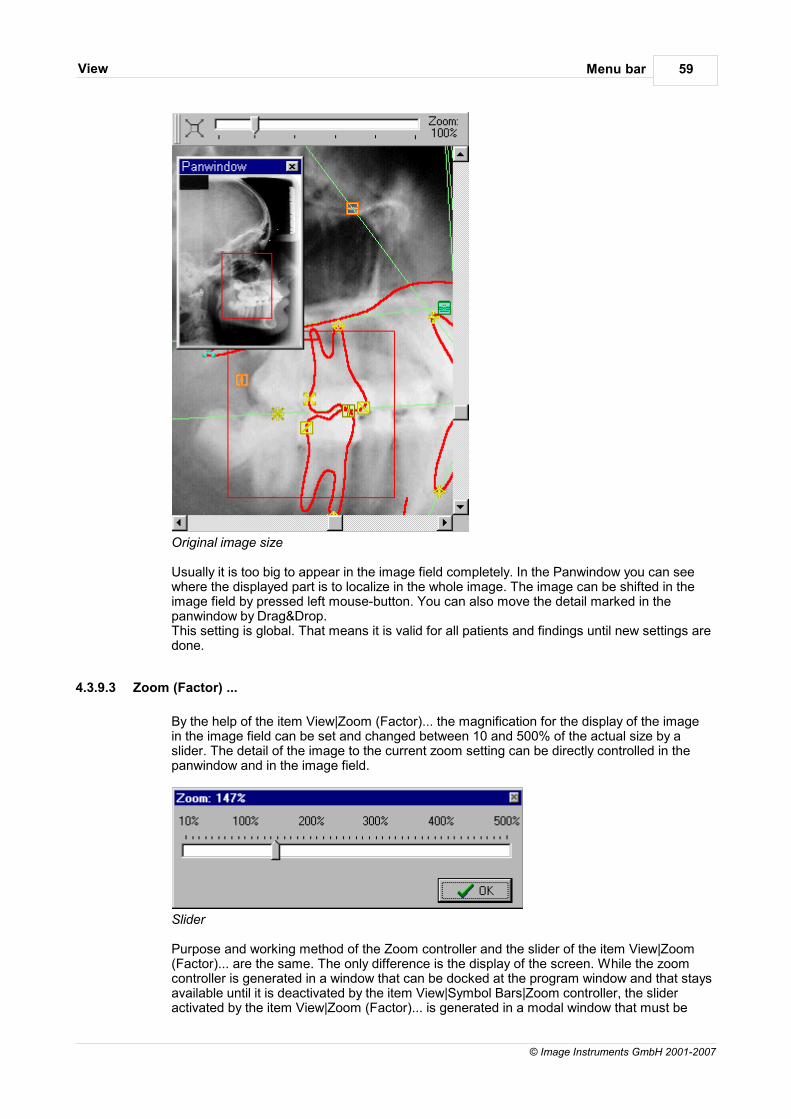
Menu barView 59
© Image Instruments GmbH 2001-2007
Original image size
Usually it is too big to appear in the image field completely. In the Panwindow you can seewhere the displayed part is to localize in the whole image. The image can be shifted in theimage field by pressed left mouse-button. You can also move the detail marked in thepanwindow by Drag&Drop.This setting is global. That means it is valid for all patients and findings until new settings aredone.
4.3.9.3 Zoom (Factor) ...
By the help of the item View|Zoom (Factor)... the magnification for the display of the imagein the image field can be set and changed between 10 and 500% of the actual size by a slider. The detail of the image to the current zoom setting can be directly controlled in thepanwindow and in the image field.
Slider
Purpose and working method of the Zoom controller and the slider of the item View|Zoom(Factor)... are the same. The only difference is the display of the screen. While the zoomcontroller is generated in a window that can be docked at the program window and that staysavailable until it is deactivated by the item View|Symbol Bars|Zoom controller, the slideractivated by the item View|Zoom (Factor)... is generated in a modal window that must be

Menu barView 60
© Image Instruments GmbH 2001-2007
closed directly after setting the wanted magnification to continue the program. Bothcontrollers work synchronized and have equal rights referring their use.
This setting is global, that means it stays valid for all patients and findings until new settingsare done.
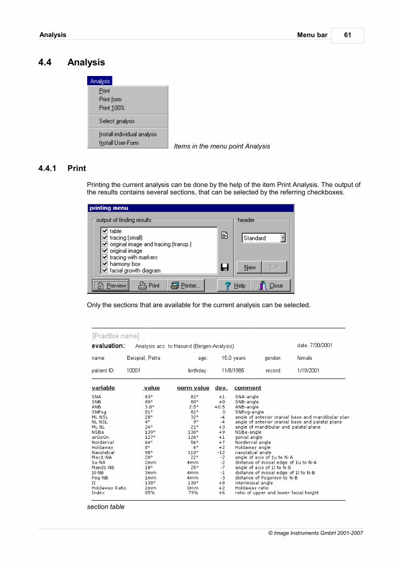
Menu barAnalysis 61
© Image Instruments GmbH 2001-2007
4.4 Analysis
Items in the menu point Analysis
4.4.1 Print
Printing the current analysis can be done by the help of the item Print Analysis. The output ofthe results contains several sections, that can be selected by the referring checkboxes.
Only the sections that are available for the current analysis can be selected.
section table
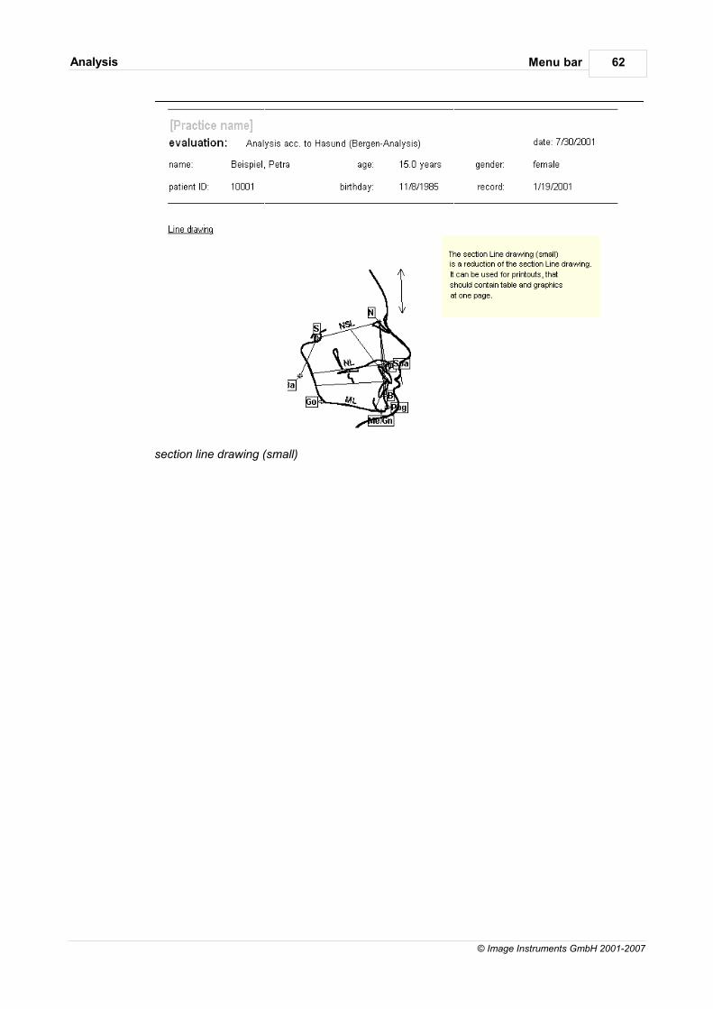
Menu barAnalysis 62
© Image Instruments GmbH 2001-2007
section line drawing (small)
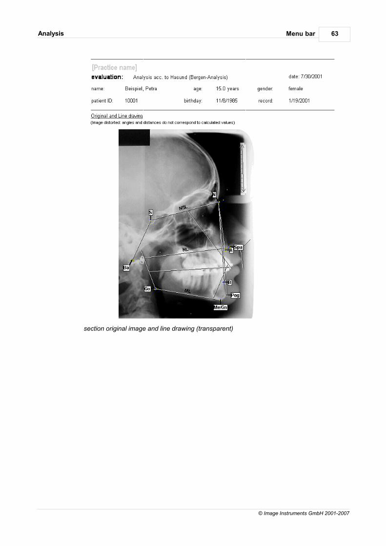
Menu barAnalysis 63
© Image Instruments GmbH 2001-2007
section original image and line drawing (transparent)
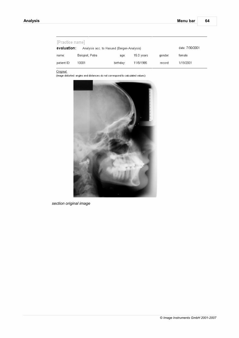
Menu barAnalysis 64
© Image Instruments GmbH 2001-2007
section original image
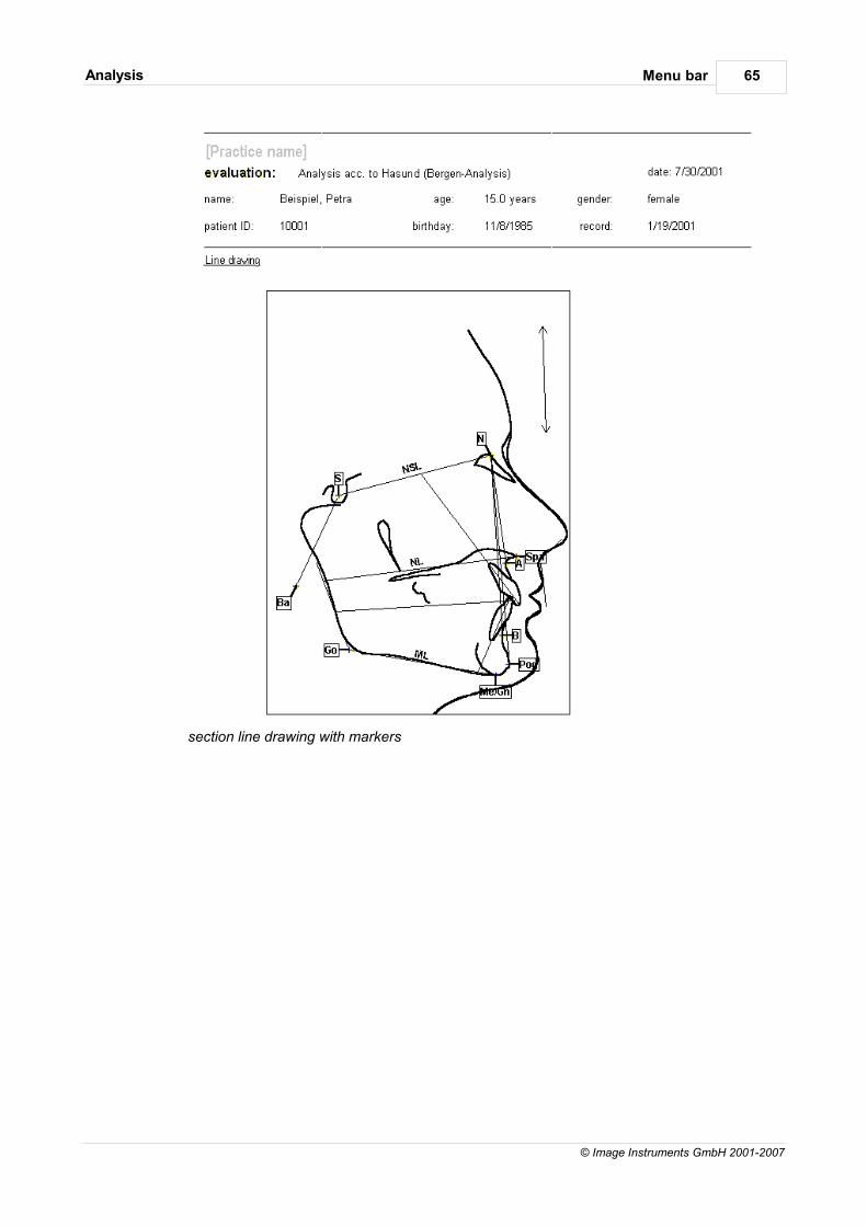
Menu barAnalysis 65
© Image Instruments GmbH 2001-2007
section line drawing with markers
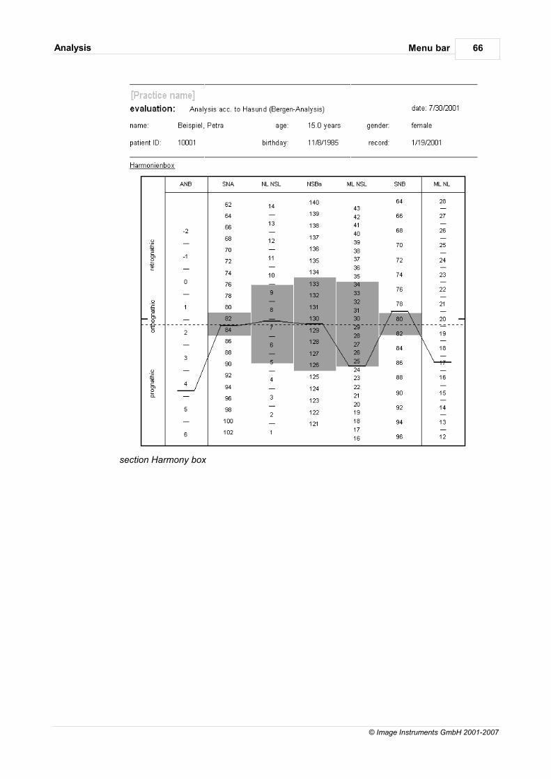
Menu barAnalysis 66
© Image Instruments GmbH 2001-2007
section Harmony box
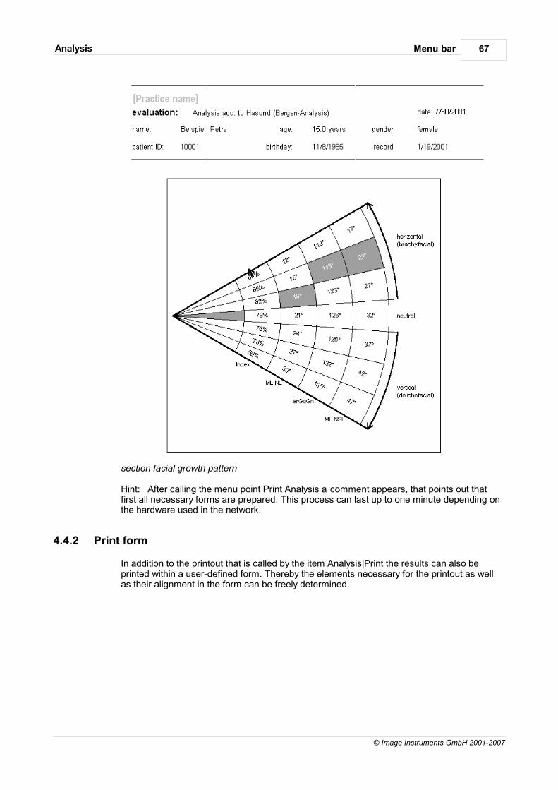
Menu barAnalysis 67
© Image Instruments GmbH 2001-2007
section facial growth pattern
Hint: After calling the menu point Print Analysis a comment appears, that points out thatfirst all necessary forms are prepared. This process can last up to one minute depending onthe hardware used in the network.
4.4.2 Print form
In addition to the printout that is called by the item Analysis|Print the results can also beprinted within a user-defined form. Thereby the elements necessary for the printout as wellas their alignment in the form can be freely determined.
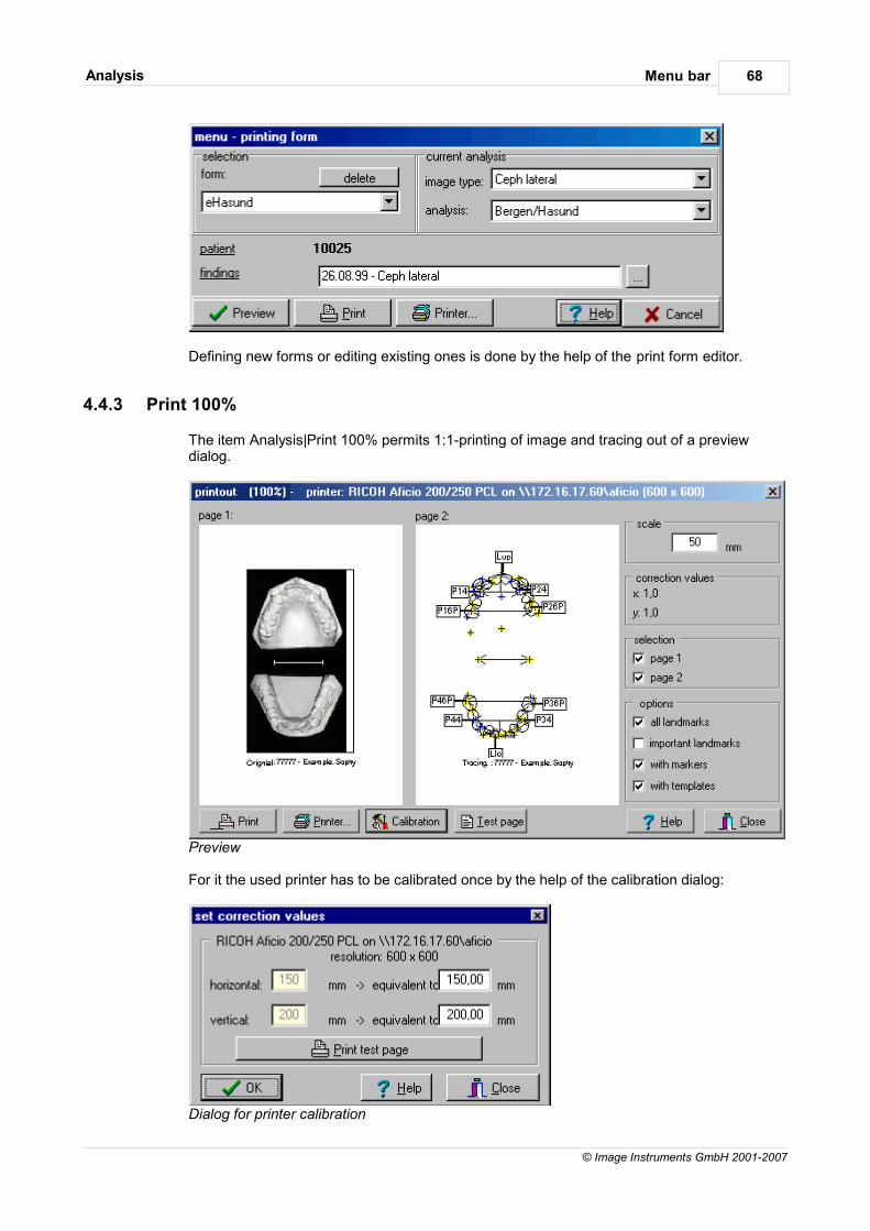
Menu barAnalysis 68
© Image Instruments GmbH 2001-2007
Defining new forms or editing existing ones is done by the help of the print form editor.
4.4.3 Print 100%
The item Analysis|Print 100% permits 1:1-printing of image and tracing out of a previewdialog.
Preview
For it the used printer has to be calibrated once by the help of the calibration dialog:
Dialog for printer calibration
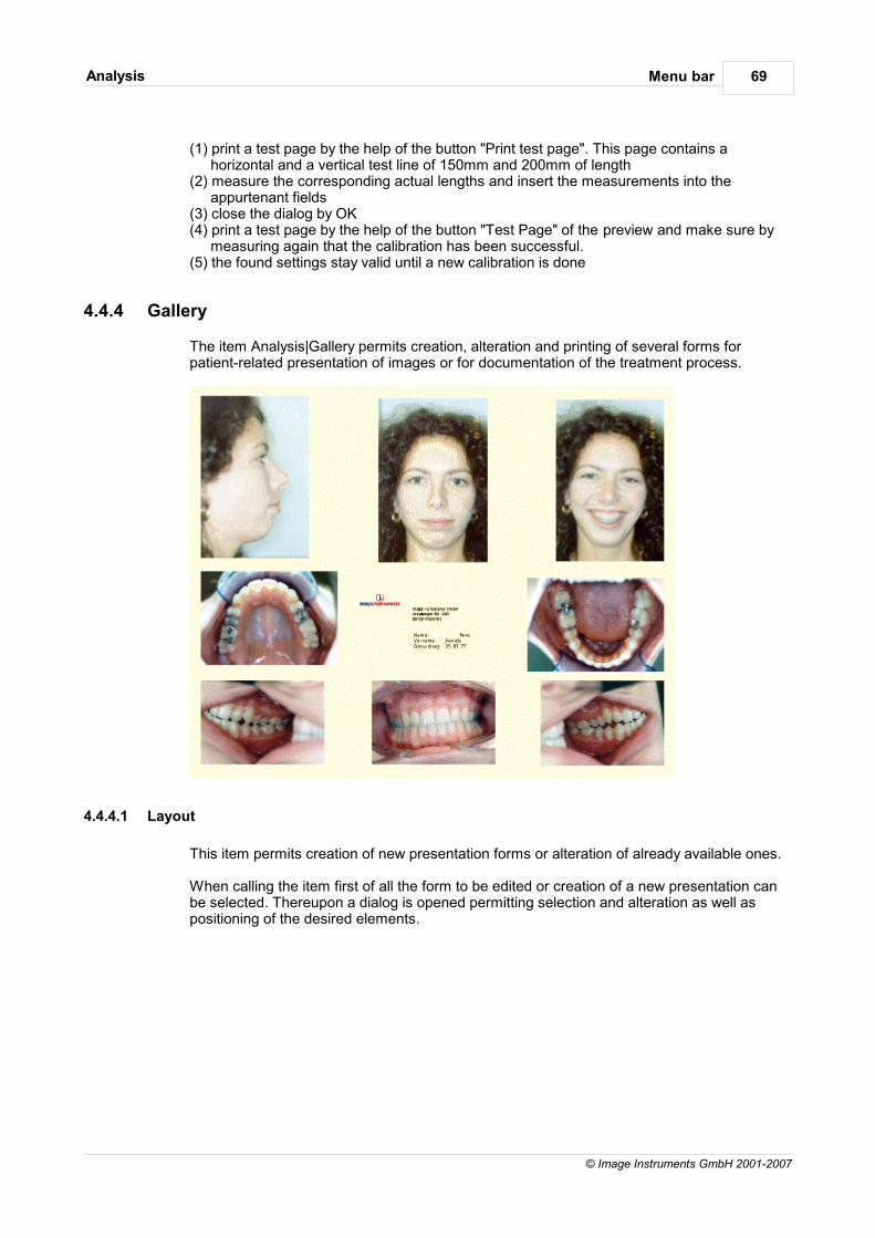
Menu barAnalysis 69
© Image Instruments GmbH 2001-2007
(1) print a test page by the help of the button "Print test page". This page contains ahorizontal and a vertical test line of 150mm and 200mm of length
(2) measure the corresponding actual lengths and insert the measurements into theappurtenant fields
(3) close the dialog by OK(4) print a test page by the help of the button "Test Page" of the preview and make sure by
measuring again that the calibration has been successful.(5) the found settings stay valid until a new calibration is done
4.4.4 Gallery
The item Analysis|Gallery permits creation, alteration and printing of several forms forpatient-related presentation of images or for documentation of the treatment process.
4.4.4.1 Layout
This item permits creation of new presentation forms or alteration of already available ones.
When calling the item first of all the form to be edited or creation of a new presentation canbe selected. Thereupon a dialog is opened permitting selection and alteration as well aspositioning of the desired elements.
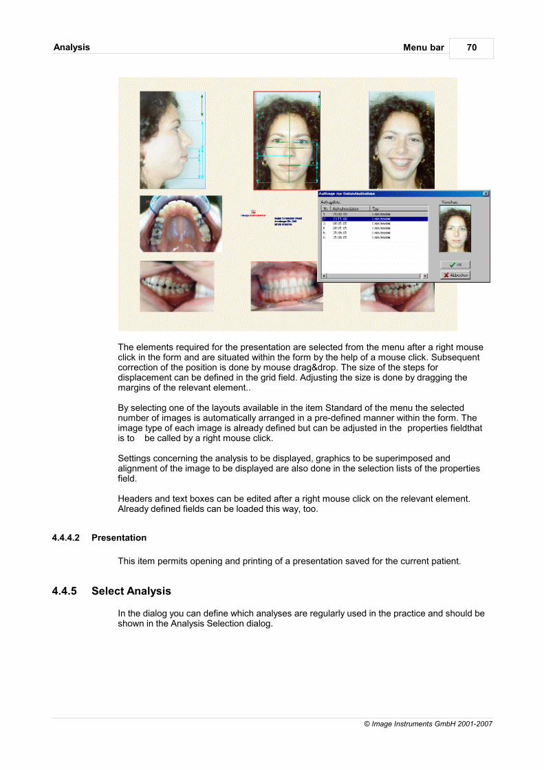
Menu barAnalysis 70
© Image Instruments GmbH 2001-2007
The elements required for the presentation are selected from the menu after a right mouseclick in the form and are situated within the form by the help of a mouse click. Subsequentcorrection of the position is done by mouse drag&drop. The size of the steps fordisplacement can be defined in the grid field. Adjusting the size is done by dragging themargins of the relevant element..
By selecting one of the layouts available in the item Standard of the menu the selectednumber of images is automatically arranged in a pre-defined manner within the form. Theimage type of each image is already defined but can be adjusted in the properties fieldthatis to be called by a right mouse click.
Settings concerning the analysis to be displayed, graphics to be superimposed andalignment of the image to be displayed are also done in the selection lists of the propertiesfield.
Headers and text boxes can be edited after a right mouse click on the relevant element.Already defined fields can be loaded this way, too.
4.4.4.2 Presentation
This item permits opening and printing of a presentation saved for the current patient.
4.4.5 Select Analysis
In the dialog you can define which analyses are regularly used in the practice and should beshown in the Analysis Selection dialog.
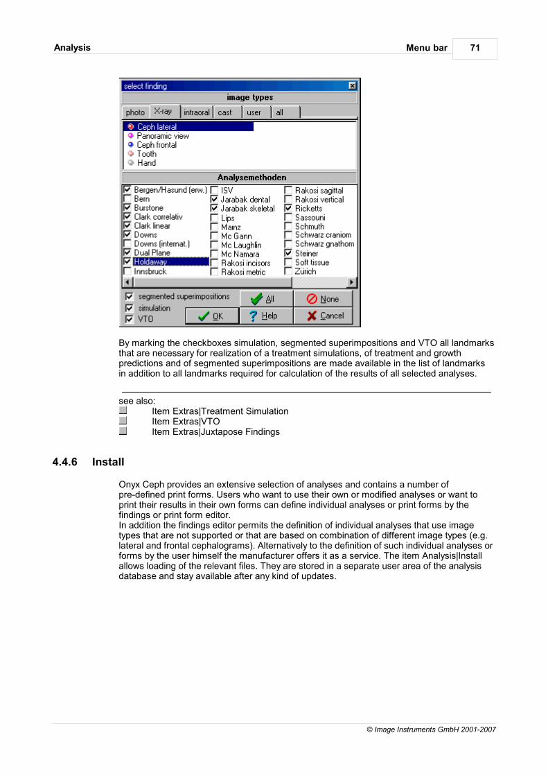
Menu barAnalysis 71
© Image Instruments GmbH 2001-2007
By marking the checkboxes simulation, segmented superimpositions and VTO all landmarksthat are necessary for realization of a treatment simulations, of treatment and growthpredictions and of segmented superimpositions are made available in the list of landmarksin addition to all landmarks required for calculation of the results of all selected analyses.
see also:Item Extras|Treatment SimulationItem Extras|VTOItem Extras|Juxtapose Findings
4.4.6 Install
Onyx Ceph provides an extensive selection of analyses and contains a number ofpre-defined print forms. Users who want to use their own or modified analyses or want toprint their results in their own forms can define individual analyses or print forms by thefindings or print form editor. In addition the findings editor permits the definition of individual analyses that use imagetypes that are not supported or that are based on combination of different image types (e.g.lateral and frontal cephalograms). Alternatively to the definition of such individual analyses orforms by the user himself the manufacturer offers it as a service. The item Analysis|Installallows loading of the relevant files. They are stored in a separate user area of the analysisdatabase and stay available after any kind of updates.
Menu barCommunication 72
© Image Instruments GmbH 2001-2007
4.5 Communication
Items in the menu point Communication
4.5.1 Exchange
The item Communication|Exchange permits transferring of findings. For that purpose data ofone ore more findings, the appurtenant master data of the patient and if required the imagesare compressed and copied into a "container-file" for easy dispatch by mail or email.
This data-exchange permits:
evaluation of findings at computers that are not integrated into the practice-network (e.g.at home)
updating of the externally evaluated findings in the main database transfer of findings to colleagues transfer of findings to evaluation laboratories, etc.
Beside the finding-data the containers for export and import of findings include informationabout the "owner" of the data. For data-exchange between computers of the own practicethis information is not necessary. If a finding of another practice is loaded, an own"client-area" for that practice is prepared. In this area the data of the container is deposited.So mixing up of patients and findings (e.g. when patient ID is identical) can be prevented.
The item Patient|Select Client permits changing between the several clients.
Please note: If the findings of a patient are exported by the help of the container newfindings for that patient must not be established in both the exporting and the importingpractice. Otherwise the findings that meanwhile have been established in the own practicewill be overwritten by the records to be imported because of identical finding-IDs.
4.5.1.1 Export
The item Exchange|Export opens the export mailbox that contains all patients of the currentclient whose findings and images were deposited there by the help of the itemsExchange|Add finding or Exchange|Add findings, respectively. For each client an own exportmailbox is available and only the one of the currently selected client is shown.
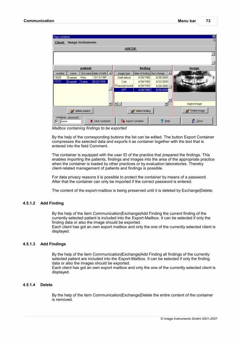
Menu barCommunication 73
© Image Instruments GmbH 2001-2007
Mailbox containing findings to be exported
By the help of the corresponding buttons the list can be edited. The button Export Containercompresses the selected data and exports it as container together with the text that isentered into the field Comment.
The container is equipped with the user ID of the practice that prepared the findings. Thisenables importing the patients, findings and images into the area of the appropriate practicewhen the container is loaded by other practices or by evaluation laboratories. Therebyclient-related management of patients and findings is possible.
For data privacy reasons it is possible to protect the container by means of a password.After that the container can only be imported if the correct password is entered.
The content of the export-mailbox is being preserved until it is deleted by Exchange|Delete.
4.5.1.2 Add Finding
By the help of the item Communication|Exchange|Add Finding the current finding of thecurrently selected patient is included into the Export-Mailbox. It can be selected if only thefinding data or also the image should be exported.Each client has got an own export mailbox and only the one of the currently selected client isdisplayed.
4.5.1.3 Add Findings
By the help of the item Communication|Exchange|Add Finding all findings of the currentlyselected patient are included into the Export-Mailbox. It can be selected if only the findingdata or also the images should be exported.Each client has got an own export mailbox and only the one of the currently selected client isdisplayed.
4.5.1.4 Delete
By the help of the item Communication|Exchange|Delete the entire content of the containeris removed.
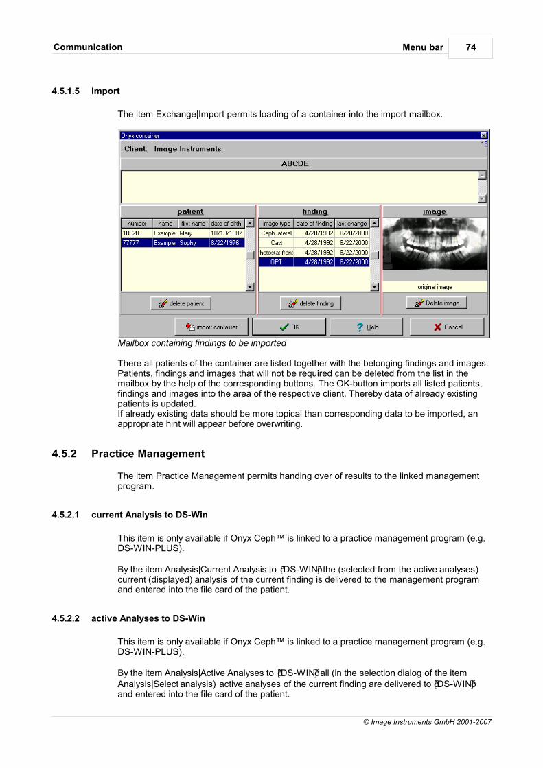
Menu barCommunication 74
© Image Instruments GmbH 2001-2007
4.5.1.5 Import
The item Exchange|Import permits loading of a container into the import mailbox.
Mailbox containing findings to be imported
There all patients of the container are listed together with the belonging findings and images.Patients, findings and images that will not be required can be deleted from the list in themailbox by the help of the corresponding buttons. The OK-button imports all listed patients,findings and images into the area of the respective client. Thereby data of already existingpatients is updated. If already existing data should be more topical than corresponding data to be imported, anappropriate hint will appear before overwriting.
4.5.2 Practice Management
The item Practice Management permits handing over of results to the linked managementprogram.
4.5.2.1 current Analysis to DS-Win
This item is only available if Onyx Ceph™ is linked to a practice management program (e.g.DS-WIN-PLUS).
By the item Analysis|Current Analysis to DS-WIN the (selected from the active analyses)current (displayed) analysis of the current finding is delivered to the management programand entered into the file card of the patient.
4.5.2.2 active Analyses to DS-Win
This item is only available if Onyx Ceph™ is linked to a practice management program (e.g.DS-WIN-PLUS).
By the item Analysis|Active Analyses to DS-WIN all (in the selection dialog of the itemAnalysis|Select analysis) active analyses of the current finding are delivered to DS-WINand entered into the file card of the patient.

Menu barCommunication 75
© Image Instruments GmbH 2001-2007
4.5.3 Export Analysis
By the help of the item Export Analysis data of the currently selected analysis can beexported in MS Excel-format or as text file. It is also possible to copy the data to theclipboard to make it available for further programs supporting working with Windowsclipboard.
4.5.4 Report
The item Communication|Report permits dispatch of findings via internet or on data mediumto colleagues who do not use Onyx software. For that purpose data of one ore morefindings, the appurtenant master data of the patient and, if required, the images arecompressed and copied into a Report-File. The addressee can open these files in anarbitrary internet browser. The findings can only be looked at but not edited by theaddressee.
4.5.4.1 Edit/Save
The item Report|Edit/Save opens the report.
Report containing the findings to be dispatched
All patients whose images and findings were deposited in the report by the help of the itemReport|Add Finding are listed there. By the respective buttons the list can be edited. Thebutton Compress packs the report and exports it together with the text inserted into thecomment-field as self-extracting Zip-file. That file contains all data that will be necessary for

Menu barCommunication 76
© Image Instruments GmbH 2001-2007
viewing it in the browser and can be dispatched.
For each client an own Report is available and only the one of the currently selected client isshown.
The content of the report is being preserved until it is deleted by the item Report|Delete.
4.5.4.2 Add Finding
The item Communication|Report|Add Finding includes the currently displayed finding of theselected patient into the Report. It can be selected which components of the finding shouldbe taken over.
For each client an own report is available and only the one of the currently selected client isshown.
4.5.4.3 Delete
The item Communication|Report|Delete removes the entire content of the report.
4.5.5 Send Message
The item Communication|Send Message permits dispatching of internal messages to anyworkstation within the practice network.

Menu barGo to 77
© Image Instruments GmbH 2001-2007
4.6 Go to
Items in the menu point Go to
4.6.1 Onyx Import
4.6.2 Onyx PVL
The optional item Go to [Onyx PVL] permits changing to self-definition of orthodonticanalyses.Onyx Ceph™ is closed because of the necessary writing access to the Onyx-database.
4.6.3 External Programs
The optional item Go to External Programs permits changing to a linked program ordocument, such as a management-program (e.g. DS-WIN-PLUS by Dampsoft) thatsupports data interfaces in common with Onyx Ceph™. These external programs can beconfigured by the help of the item Options|External Programs.
Hint:Users of DS-Win-PLUS can configure Onyx Ceph™ as DS-Win-Onyx Ceph™ by the interface dialog of the menu point Options|External Programs. Then additional items appearin the Onyx Ceph™ menu (Go to|DS-Win, Communication|Practice Management)supporting mutual data exchange between both programs.
Calling Onyx Ceph™ from DS-WIN is done by the button [Onyx-Ceph] beside the file card ofthe chosen patient. (If this button does not already exist, you may activate it by the button[ext. programs] in the same window.)
After finishing setting up the image finding for the chosen patient or patients, you can returnto the program where you called Onyx Ceph™ from by the menu point Go to|ExternalPrograms. Results and images can be delivered to the image database and to the file cardin DS-WIN for the current analysis or for all analyses.
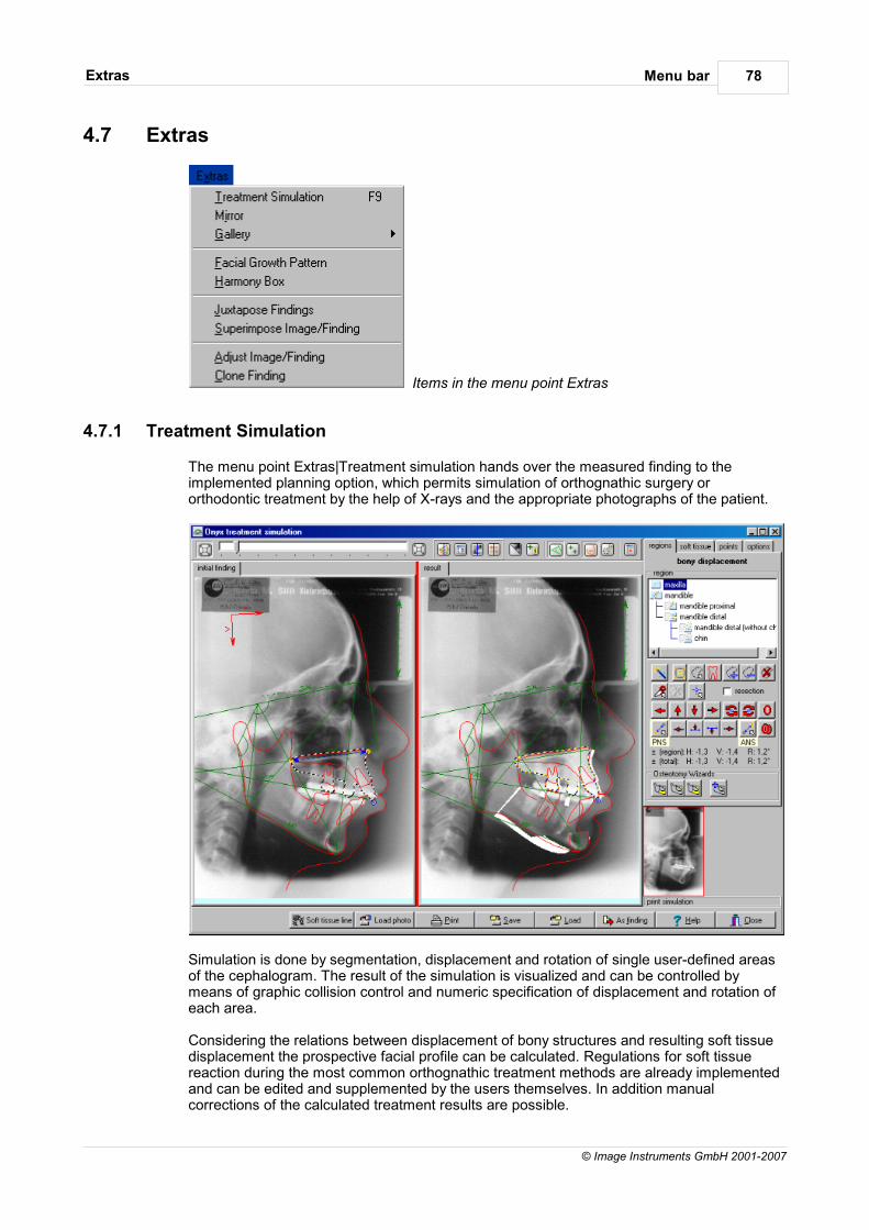
Menu barExtras 78
© Image Instruments GmbH 2001-2007
4.7 Extras
Items in the menu point Extras
4.7.1 Treatment Simulation
The menu point Extras|Treatment simulation hands over the measured finding to theimplemented planning option, which permits simulation of orthognathic surgery ororthodontic treatment by the help of X-rays and the appropriate photographs of the patient.
Simulation is done by segmentation, displacement and rotation of single user-defined areasof the cephalogram. The result of the simulation is visualized and can be controlled bymeans of graphic collision control and numeric specification of displacement and rotation ofeach area.
Considering the relations between displacement of bony structures and resulting soft tissuedisplacement the prospective facial profile can be calculated. Regulations for soft tissuereaction during the most common orthognathic treatment methods are already implementedand can be edited and supplemented by the users themselves. In addition manualcorrections of the calculated treatment results are possible.
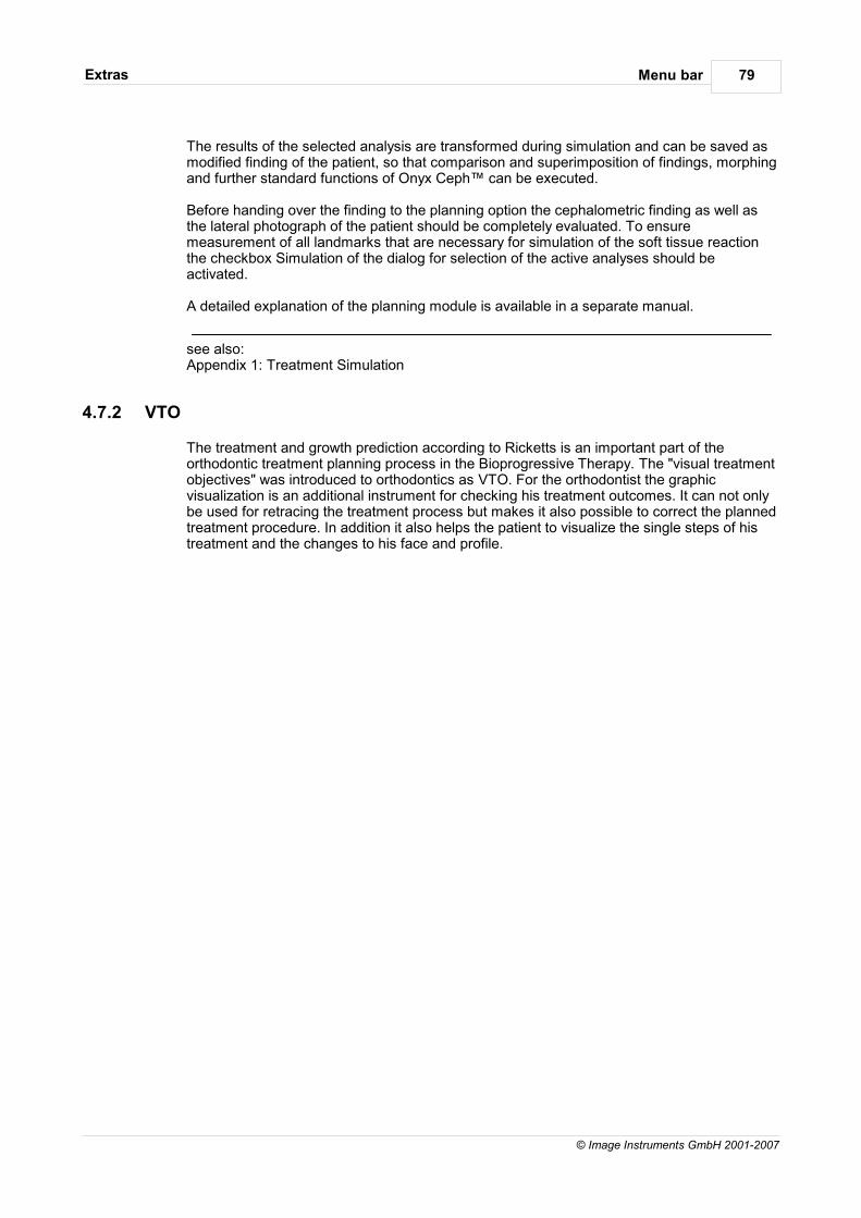
Menu barExtras 79
© Image Instruments GmbH 2001-2007
The results of the selected analysis are transformed during simulation and can be saved asmodified finding of the patient, so that comparison and superimposition of findings, morphingand further standard functions of Onyx Ceph™ can be executed.
Before handing over the finding to the planning option the cephalometric finding as well asthe lateral photograph of the patient should be completely evaluated. To ensuremeasurement of all landmarks that are necessary for simulation of the soft tissue reactionthe checkbox Simulation of the dialog for selection of the active analyses should beactivated.
A detailed explanation of the planning module is available in a separate manual.
see also:Appendix 1: Treatment Simulation
4.7.2 VTO
The treatment and growth prediction according to Ricketts is an important part of theorthodontic treatment planning process in the Bioprogressive Therapy. The "visual treatmentobjectives" was introduced to orthodontics as VTO. For the orthodontist the graphicvisualization is an additional instrument for checking his treatment outcomes. It can not onlybe used for retracing the treatment process but makes it also possible to correct the plannedtreatment procedure. In addition it also helps the patient to visualize the single steps of histreatment and the changes to his face and profile.
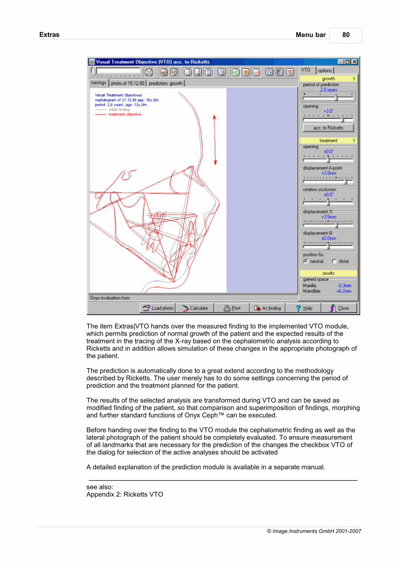
Menu barExtras 80
© Image Instruments GmbH 2001-2007
The item Extras|VTO hands over the measured finding to the implemented VTO module,which permits prediction of normal growth of the patient and the expected results of thetreatment in the tracing of the X-ray based on the cephalometric analysis according toRicketts and in addition allows simulation of these changes in the appropriate photograph ofthe patient.
The prediction is automatically done to a great extend according to the methodologydescribed by Ricketts. The user merely has to do some settings concerning the period ofprediction and the treatment planned for the patient. The results of the selected analysis are transformed during VTO and can be saved asmodified finding of the patient, so that comparison and superimposition of findings, morphingand further standard functions of Onyx Ceph™ can be executed.
Before handing over the finding to the VTO module the cephalometric finding as well as thelateral photograph of the patient should be completely evaluated. To ensure measurementof all landmarks that are necessary for the prediction of the changes the checkbox VTO ofthe dialog for selection of the active analyses should be activated
A detailed explanation of the prediction module is available in a separate manual.
see also:Appendix 2: Ricketts VTO
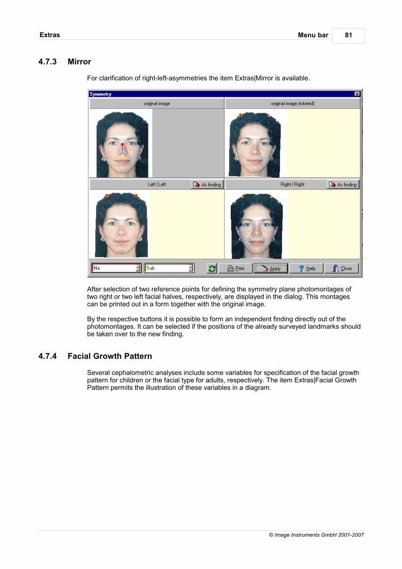
Menu barExtras 81
© Image Instruments GmbH 2001-2007
4.7.3 Mirror
For clarification of right-left-asymmetries the item Extras|Mirror is available.
After selection of two reference points for defining the symmetry plane photomontages oftwo right or two left facial halves, respectively, are displayed in the dialog. This montagescan be printed out in a form together with the original image.
By the respective buttons it is possible to form an independent finding directly out of thephotomontages. It can be selected if the positions of the already surveyed landmarks shouldbe taken over to the new finding.
4.7.4 Facial Growth Pattern
Several cephalometric analyses include some variables for specification of the facial growthpattern for children or the facial type for adults, respectively. The item Extras|Facial GrowthPattern permits the illustration of these variables in a diagram.
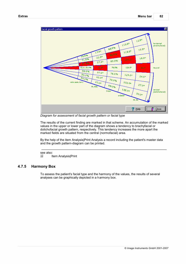
Menu barExtras 82
© Image Instruments GmbH 2001-2007
Diagram for assessment of facial growth pattern or facial type
The results of the current finding are marked in that scheme. An accumulation of the markedvalues in the upper or lower part of the diagram shows a tendency to brachyfacial ordolichofacial growth pattern, respectively. This tendency increases the more apart themarked fields are situated from the central (normofacial) area.
By the help of the item Analysis|Print Analysis a record including the patient's master dataand the growth pattern-diagram can be printed.
see also:Item Analysis|Print
4.7.5 Harmony Box
To assess the patient's facial type and the harmony of the values, the results of severalanalyses can be graphically depicted in a harmony box.
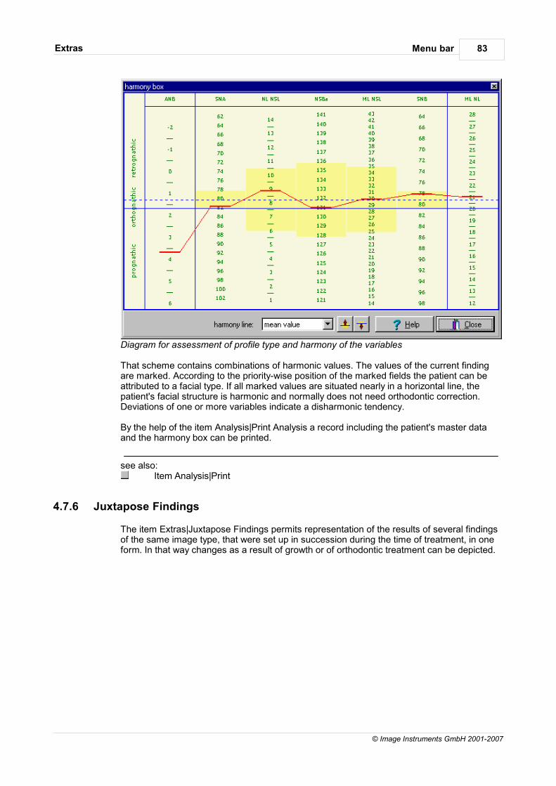
Menu barExtras 83
© Image Instruments GmbH 2001-2007
Diagram for assessment of profile type and harmony of the variables
That scheme contains combinations of harmonic values. The values of the current findingare marked. According to the priority-wise position of the marked fields the patient can beattributed to a facial type. If all marked values are situated nearly in a horizontal line, thepatient's facial structure is harmonic and normally does not need orthodontic correction.Deviations of one or more variables indicate a disharmonic tendency.
By the help of the item Analysis|Print Analysis a record including the patient's master dataand the harmony box can be printed.
see also:Item Analysis|Print
4.7.6 Juxtapose Findings
The item Extras|Juxtapose Findings permits representation of the results of several findingsof the same image type, that were set up in succession during the time of treatment, in one form. In that way changes as a result of growth or of orthodontic treatment can be depicted.
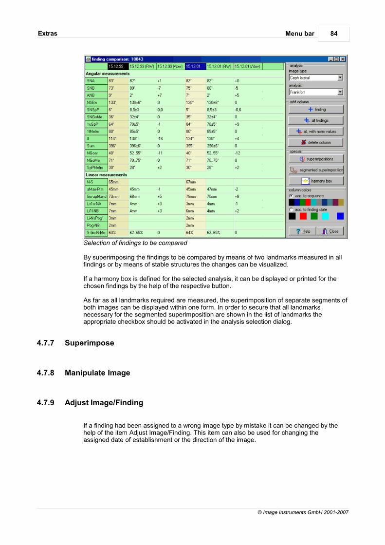
Menu barExtras 84
© Image Instruments GmbH 2001-2007
Selection of findings to be compared
By superimposing the findings to be compared by means of two landmarks measured in allfindings or by means of stable structures the changes can be visualized.
If a harmony box is defined for the selected analysis, it can be displayed or printed for thechosen findings by the help of the respective button.
As far as all landmarks required are measured, the superimposition of separate segments ofboth images can be displayed within one form. In order to secure that all landmarksnecessary for the segmented superimposition are shown in the list of landmarks theappropriate checkbox should be activated in the analysis selection dialog.
4.7.7 Superimpose
4.7.8 Manipulate Image
4.7.9 Adjust Image/Finding
If a finding had been assigned to a wrong image type by mistake it can be changed by thehelp of the item Adjust Image/Finding. This item can also be used for changing theassigned date of establishment or the direction of the image.
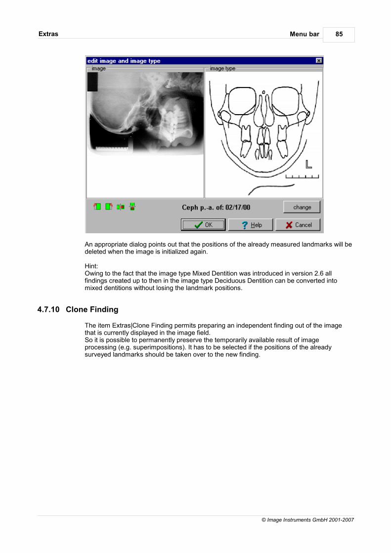
Menu barExtras 85
© Image Instruments GmbH 2001-2007
An appropriate dialog points out that the positions of the already measured landmarks will bedeleted when the image is initialized again.
Hint:Owing to the fact that the image type Mixed Dentition was introduced in version 2.6 allfindings created up to then in the image type Deciduous Dentition can be converted intomixed dentitions without losing the landmark positions.
4.7.10 Clone Finding
The item Extras|Clone Finding permits preparing an independent finding out of the imagethat is currently displayed in the image field.So it is possible to permanently preserve the temporarily available result of imageprocessing (e.g. superimpositions). It has to be selected if the positions of the alreadysurveyed landmarks should be taken over to the new finding.
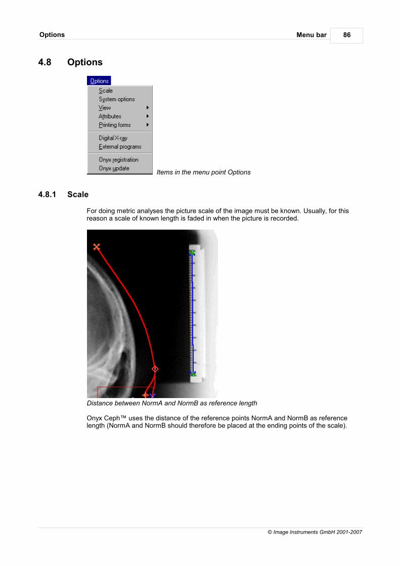
Menu barOptions 86
© Image Instruments GmbH 2001-2007
4.8 Options
Items in the menu point Options
4.8.1 Scale
For doing metric analyses the picture scale of the image must be known. Usually, for thisreason a scale of known length is faded in when the picture is recorded.
Distance between NormA and NormB as reference length
Onyx Ceph™ uses the distance of the reference points NormA and NormB as referencelength (NormA and NormB should therefore be placed at the ending points of the scale).
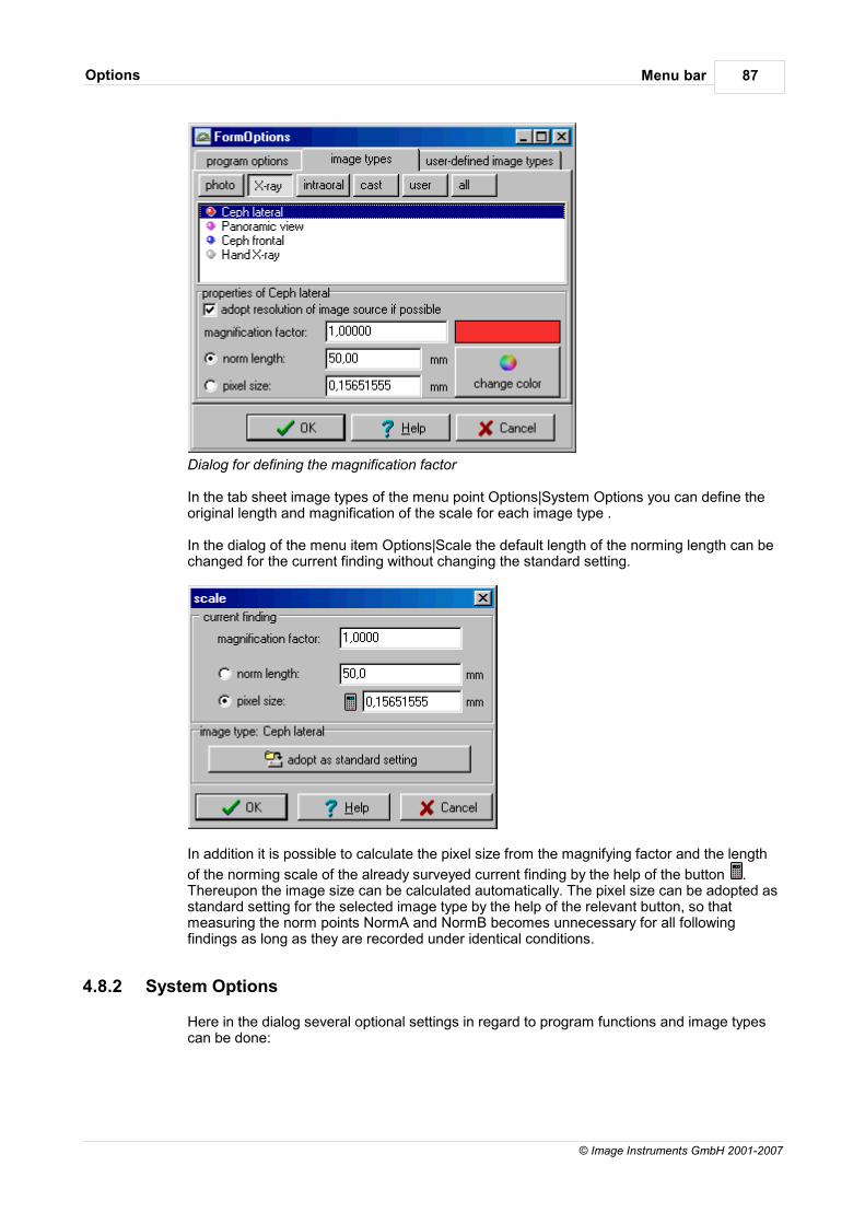
Menu barOptions 87
© Image Instruments GmbH 2001-2007
Dialog for defining the magnification factor
In the tab sheet image types of the menu point Options|System Options you can define theoriginal length and magnification of the scale for each image type .
In the dialog of the menu item Options|Scale the default length of the norming length can bechanged for the current finding without changing the standard setting.
In addition it is possible to calculate the pixel size from the magnifying factor and the length
of the norming scale of the already surveyed current finding by the help of the button .Thereupon the image size can be calculated automatically. The pixel size can be adopted asstandard setting for the selected image type by the help of the relevant button, so thatmeasuring the norm points NormA and NormB becomes unnecessary for all followingfindings as long as they are recorded under identical conditions.
4.8.2 System Options
Here in the dialog several optional settings in regard to program functions and image typescan be done:
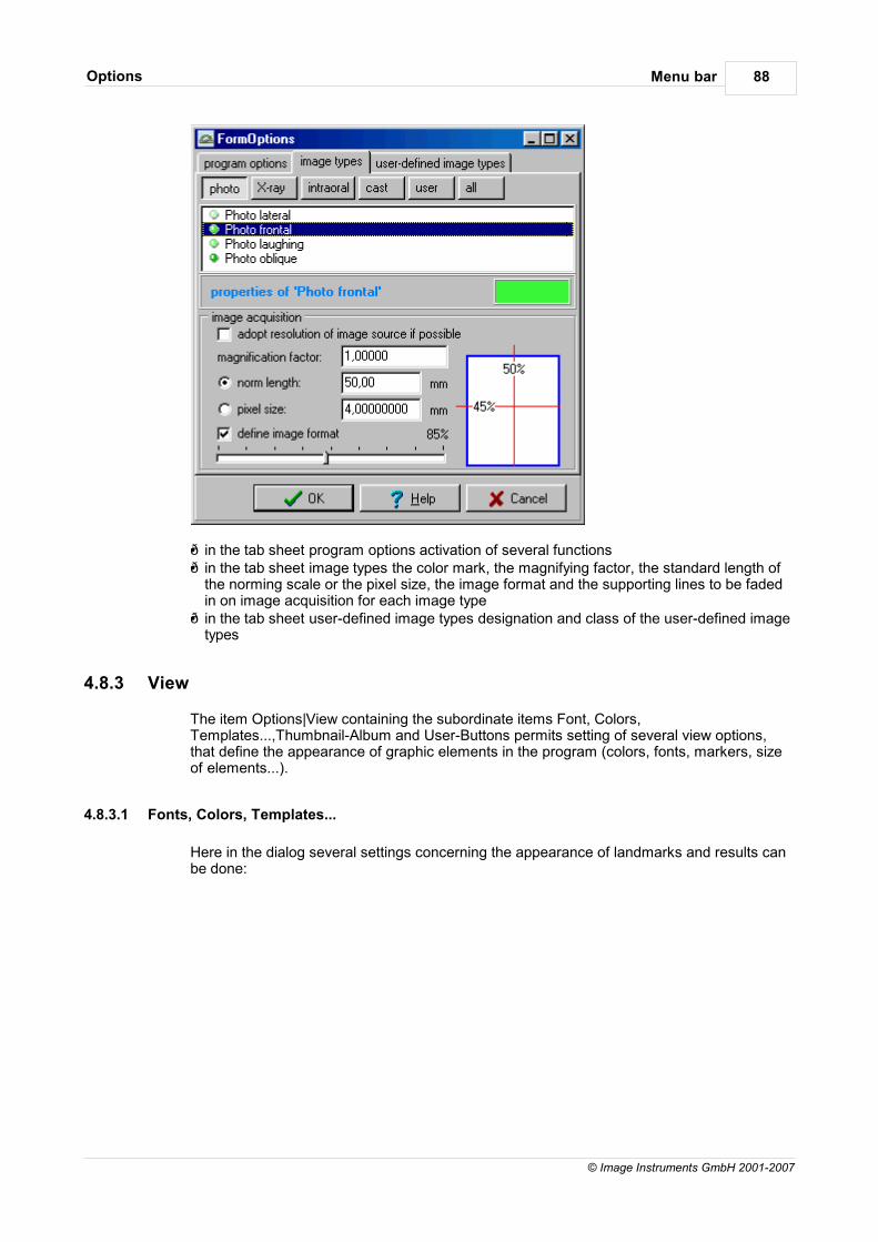
Menu barOptions 88
© Image Instruments GmbH 2001-2007
in the tab sheet program options activation of several functions in the tab sheet image types the color mark, the magnifying factor, the standard length of
the norming scale or the pixel size, the image format and the supporting lines to be fadedin on image acquisition for each image type in the tab sheet user-defined image types designation and class of the user-defined image
types
4.8.3 View
The item Options|View containing the subordinate items Font, Colors,Templates...,Thumbnail-Album and User-Buttons permits setting of several view options,that define the appearance of graphic elements in the program (colors, fonts, markers, sizeof elements...).
4.8.3.1 Fonts, Colors, Templates...
Here in the dialog several settings concerning the appearance of landmarks and results canbe done:
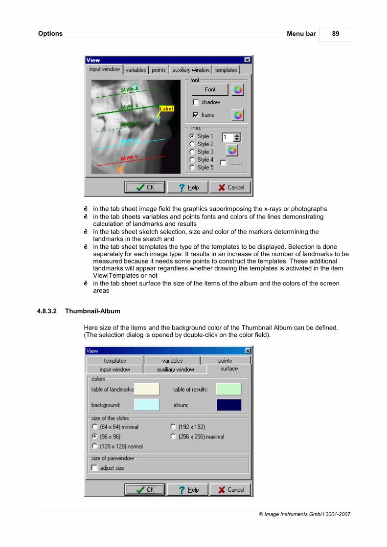
Menu barOptions 89
© Image Instruments GmbH 2001-2007
in the tab sheet image field the graphics superimposing the x-rays or photographs in the tab sheets variables and points fonts and colors of the lines demonstrating
calculation of landmarks and results in the tab sheet sketch selection, size and color of the markers determining the
landmarks in the sketch and in the tab sheet templates the type of the templates to be displayed. Selection is done
separately for each image type. It results in an increase of the number of landmarks to bemeasured because it needs some points to construct the templates. These additionallandmarks will appear regardless whether drawing the templates is activated in the itemView|Templates or not
in the tab sheet surface the size of the items of the album and the colors of the screenareas
4.8.3.2 Thumbnail-Album
Here size of the items and the background color of the Thumbnail Album can be defined.(The selection dialog is opened by double-click on the color field).
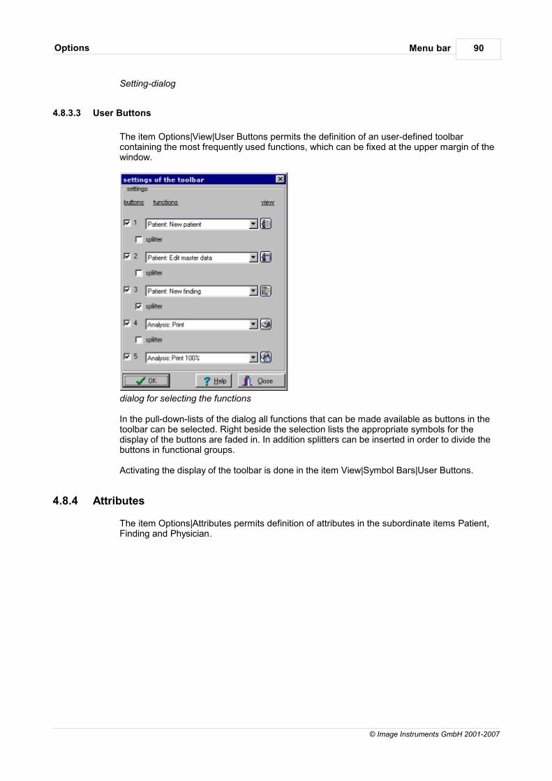
Menu barOptions 90
© Image Instruments GmbH 2001-2007
Setting-dialog
4.8.3.3 User Buttons
The item Options|View|User Buttons permits the definition of an user-defined toolbarcontaining the most frequently used functions, which can be fixed at the upper margin of thewindow.
dialog for selecting the functions
In the pull-down-lists of the dialog all functions that can be made available as buttons in thetoolbar can be selected. Right beside the selection lists the appropriate symbols for thedisplay of the buttons are faded in. In addition splitters can be inserted in order to divide thebuttons in functional groups.
Activating the display of the toolbar is done in the item View|Symbol Bars|User Buttons.
4.8.4 Attributes
The item Options|Attributes permits definition of attributes in the subordinate items Patient,Finding and Physician.
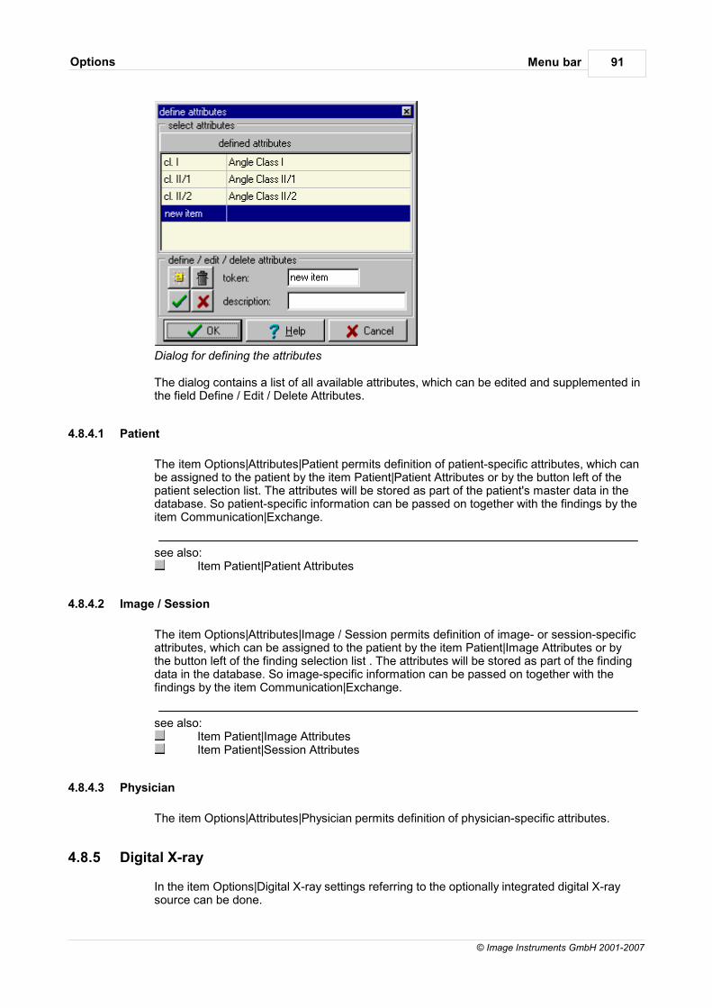
Menu barOptions 91
© Image Instruments GmbH 2001-2007
Dialog for defining the attributes
The dialog contains a list of all available attributes, which can be edited and supplemented inthe field Define / Edit / Delete Attributes.
4.8.4.1 Patient
The item Options|Attributes|Patient permits definition of patient-specific attributes, which canbe assigned to the patient by the item Patient|Patient Attributes or by the button left of thepatient selection list. The attributes will be stored as part of the patient's master data in thedatabase. So patient-specific information can be passed on together with the findings by theitem Communication|Exchange.
see also:Item Patient|Patient Attributes
4.8.4.2 Image / Session
The item Options|Attributes|Image / Session permits definition of image- or session-specificattributes, which can be assigned to the patient by the item Patient|Image Attributes or bythe button left of the finding selection list . The attributes will be stored as part of the findingdata in the database. So image-specific information can be passed on together with thefindings by the item Communication|Exchange.
see also:Item Patient|Image AttributesItem Patient|Session Attributes
4.8.4.3 Physician
The item Options|Attributes|Physician permits definition of physician-specific attributes.
4.8.5 Digital X-ray
In the item Options|Digital X-ray settings referring to the optionally integrated digital X-raysource can be done.
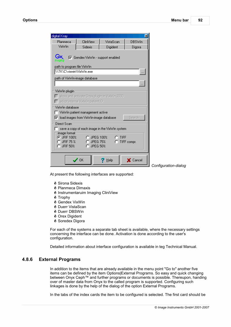
Menu barOptions 92
© Image Instruments GmbH 2001-2007
Configuration-dialog
At present the following interfaces are supported:
Sirona Sidexis Planmeca Dimaxis Instrumentaruim Imaging CliniView Trophy Gendex VixWin Duerr VistaScan Duerr DBSWin Orex Digident Soredex Digora
For each of the systems a separate tab sheet is available, where the necessary settingsconcerning the interface can be done. Activation is done according to the user'sconfiguration.
Detailed information about interface configuration is available in teg Technical Manual.
4.8.6 External Programs
In addition to the items that are already available in the menu point "Go to" another fiveitems can be defined by the item Options|External Programs. So easy and quick changingbetween Onyx Ceph™ and further programs or documents is possible. Thereupon, handingover of master data from Onyx to the called program is supported. Configuring suchlinkages is done by the help of the dialog of the option External Programs.
In the tabs of the index cards the item to be configured is selected. The first card should be
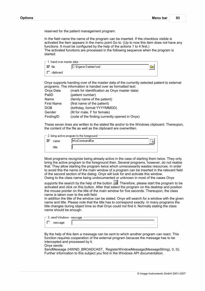
Menu barOptions 93
© Image Instruments GmbH 2001-2007
reserved for the patient management program.
In the field name the name of the program can be inserted. If the checkbox visible isactivated the item appears in the menu point Go to. (Up to now this item does not have anyfunctions. It must be configured by the help of the actions 1 to 4 first.) The activated functions are processed in the following sequence when the program isstarted:
Onyx supports handing over of the master data of the currently selected patient to externalprograms. The information is handed over as formatted text:Onyx Data (mark for identification as Onyx master data)
PatID (patient number)
Name (family name of the patient)
First Name (first name of the patient)
DOB (birthday, format YYYYMMDD)
Gender (M for male, F for female)
FindingID (code of the finding currently opened in Onyx)
These seven lines are written to the stated file and/or to the Windows clipboard. Thereupon,the content of the file as well as the clipboard are overwritten.
Most programs recognize being already active in the case of starting them twice. They onlybring the active program to the foreground then. Several programs, however, do not realizethat. They allow starting the program twice which unnecessarily wastes resources. In orderto avoid this the name of the main window of a program can be inserted in the relevant fieldof the second section of the dialog. Onyx will look for and activate this window. Owing to the class name being undocumented or unknown in most of the cases Onyx
supports the search by the help of the button . Therefore, please start the program to beactivated and click on this button. After that select the program on the desktop and positionthe mouse pointer on the title of the main window for five seconds. Thereupon, the classname is taken over to the edit field.In addition the title of the window can be stated. Onyx will search for a window with the givenname and title. Please note that the title has to correspond exactly. In many programs thetitle changes during object time so that Onyx could not find it. Normally stating the classname should be enough.
By the help of this item a message can be sent to which another program can react. Thisfunction requires cooperation of the external program because the message has to beintercepted and processed by it. Onyx sends: SendMessage (HWND_BROADCAST, RegisterWindowMessage(MessageString), 0, 0);Further information to this subject you find in the Windows API documentation.
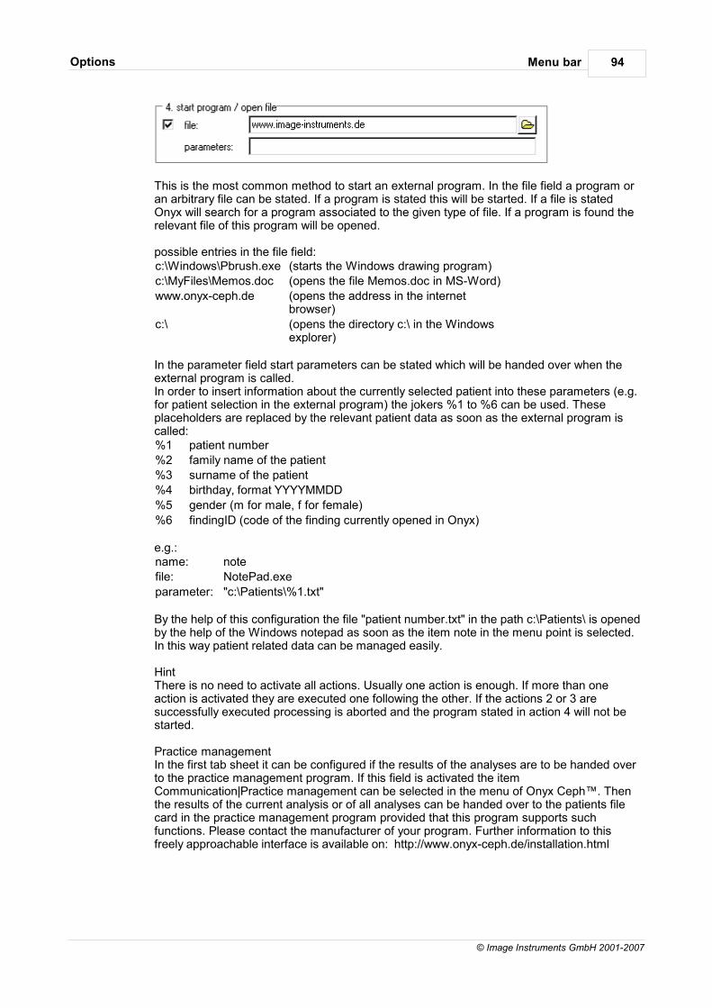
Menu barOptions 94
© Image Instruments GmbH 2001-2007
This is the most common method to start an external program. In the file field a program oran arbitrary file can be stated. If a program is stated this will be started. If a file is statedOnyx will search for a program associated to the given type of file. If a program is found therelevant file of this program will be opened.
possible entries in the file field:c:\Windows\Pbrush.exe (starts the Windows drawing program)
c:\MyFiles\Memos.doc (opens the file Memos.doc in MS-Word)
www.onyx-ceph.de (opens the address in the internetbrowser)
c:\ (opens the directory c:\ in the Windowsexplorer)
In the parameter field start parameters can be stated which will be handed over when theexternal program is called. In order to insert information about the currently selected patient into these parameters (e.g.for patient selection in the external program) the jokers %1 to %6 can be used. Theseplaceholders are replaced by the relevant patient data as soon as the external program iscalled:%1 patient number
%2 family name of the patient
%3 surname of the patient
%4 birthday, format YYYYMMDD
%5 gender (m for male, f for female)
%6 findingID (code of the finding currently opened in Onyx)
e.g.:name: note
file: NotePad.exe
parameter: "c:\Patients\%1.txt"
By the help of this configuration the file "patient number.txt" in the path c:\Patients\ is openedby the help of the Windows notepad as soon as the item note in the menu point is selected.In this way patient related data can be managed easily.
HintThere is no need to activate all actions. Usually one action is enough. If more than oneaction is activated they are executed one following the other. If the actions 2 or 3 aresuccessfully executed processing is aborted and the program stated in action 4 will not bestarted.
Practice managementIn the first tab sheet it can be configured if the results of the analyses are to be handed overto the practice management program. If this field is activated the itemCommunication|Practice management can be selected in the menu of Onyx Ceph™. Thenthe results of the current analysis or of all analyses can be handed over to the patients filecard in the practice management program provided that this program supports suchfunctions. Please contact the manufacturer of your program. Further information to thisfreely approachable interface is available on: http://www.onyx-ceph.de/installation.html
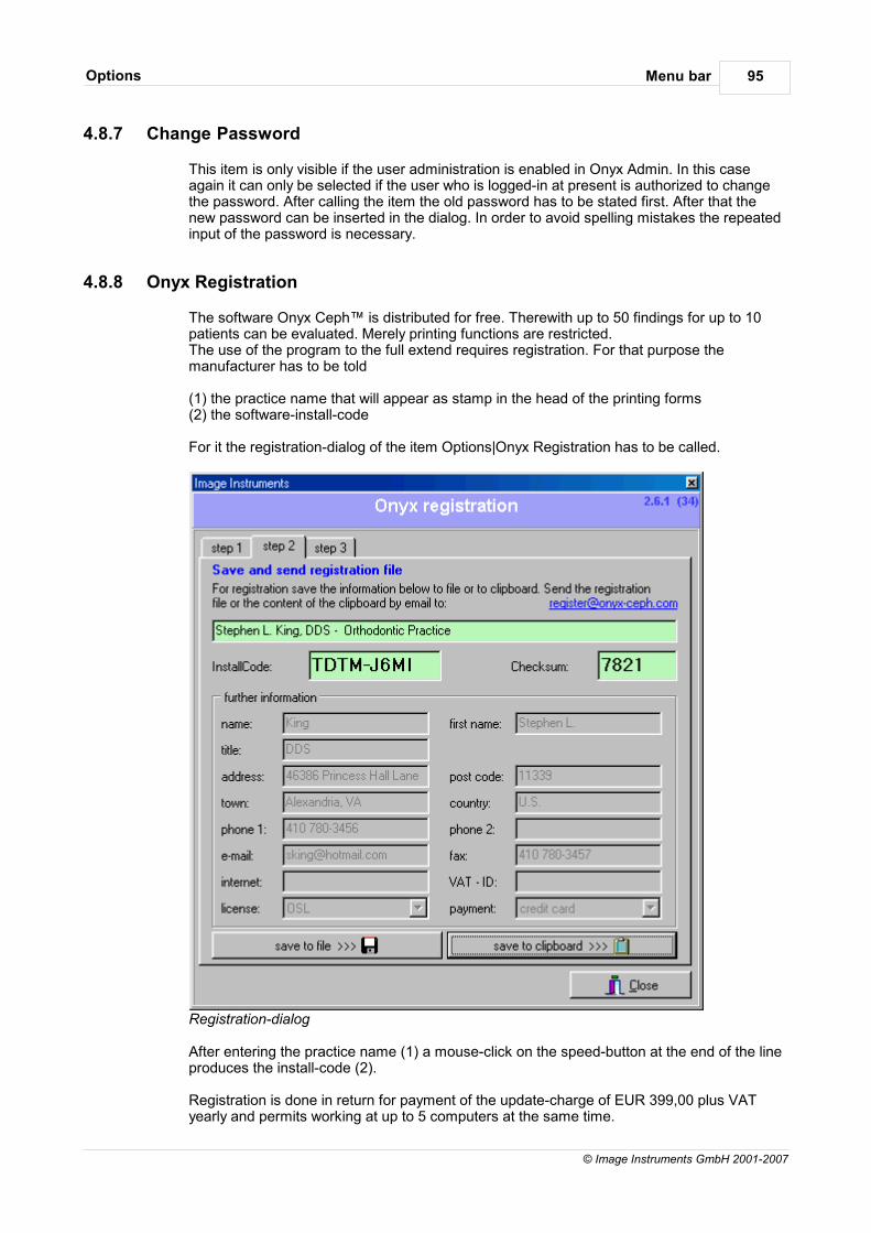
Menu barOptions 95
© Image Instruments GmbH 2001-2007
4.8.7 Change Password
This item is only visible if the user administration is enabled in Onyx Admin. In this caseagain it can only be selected if the user who is logged-in at present is authorized to changethe password. After calling the item the old password has to be stated first. After that thenew password can be inserted in the dialog. In order to avoid spelling mistakes the repeatedinput of the password is necessary.
4.8.8 Onyx Registration
The software Onyx Ceph™ is distributed for free. Therewith up to 50 findings for up to 10patients can be evaluated. Merely printing functions are restricted.The use of the program to the full extend requires registration. For that purpose themanufacturer has to be told
(1) the practice name that will appear as stamp in the head of the printing forms (2) the software-install-code
For it the registration-dialog of the item Options|Onyx Registration has to be called.
Registration-dialog
After entering the practice name (1) a mouse-click on the speed-button at the end of the lineproduces the install-code (2).
Registration is done in return for payment of the update-charge of EUR 399,00 plus VATyearly and permits working at up to 5 computers at the same time.
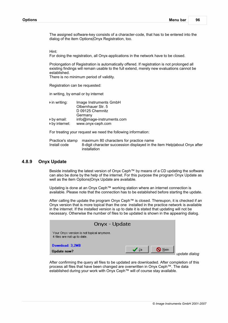
Menu barOptions 96
© Image Instruments GmbH 2001-2007
The assigned software-key consists of a character-code, that has to be entered into thedialog of the item Options|Onyx Registration, too.
Hint:For doing the registration, all Onyx-applications in the network have to be closed.
Prolongation of Registration is automatically offered. If registration is not prolonged allexisting findings will remain usable to the full extend, merely new evaluations cannot beestablished.There is no minimum period of validity.
Registration can be requested:
in writing, by email or by internet
in writing: Image Instruments GmbHOlbernhauer Str. 5D 09125 ChemnitzGermany
by email: [email protected] by internet: www.onyx-ceph.com
For treating your request we need the following information:
Practice's stamp maximum 80 characters for practice nameInstall code 8-digit character succession displayed in the item Help|about Onyx after
installation
4.8.9 Onyx Update
Beside installing the latest version of Onyx Ceph™ by means of a CD updating the softwarecan also be done by the help of the internet. For this purpose the program Onyx Update aswell as the item Options|Onyx Update are available.
Updating is done at an Onyx Ceph™ working station where an internet connection isavailable. Please note that the connection has to be established before starting the update.
After calling the update the program Onyx Ceph™ is closed. Thereupon, it is checked if anOnyx version that is more topical than the one installed in the practice network is availablein the internet. If the installed version is up to date it is stated that updating will not benecessary. Otherwise the number of files to be updated is shown in the appearing dialog.
update dialog
After confirming the query all files to be updated are downloaded. After completion of thisprocess all files that have been changed are overwritten in Onyx Ceph™. The dataestablished during your work with Onyx Ceph™ will of course stay available.

Menu barOptions 97
© Image Instruments GmbH 2001-2007
4.8.10 Onyx Server
By this item details about the Onyx Ceph database server can be displayed. Besides it ispossible to disconnect the server and to restore the connection.
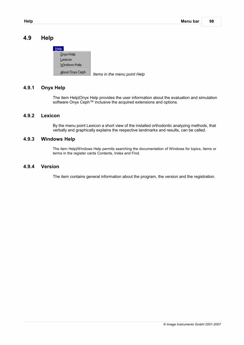
Menu barHelp 98
© Image Instruments GmbH 2001-2007
4.9 Help
Items in the menu point Help
4.9.1 Onyx Help
The item Help|Onyx Help provides the user information about the evaluation and simulationsoftware Onyx Ceph™ inclusive the acquired extensions and options.
4.9.2 Lexicon
By the menu point Lexicon a short view of the installed orthodontic analyzing methods, thatverbally and graphically explains the respective landmarks and results, can be called.
4.9.3 Windows Help
The item Help|Windows Help permits searching the documentation of Windows for topics, items orterms in the register cards Contents, Index and Find.
4.9.4 Version
The item contains general information about the program, the version and the registration.

Menu barProfile 99
© Image Instruments GmbH 2001-2007
4.10 Profile
By selection of an appropriate user profile the volume of the program Onyx Ceph can beadapted to the user's training or to the individual requirements in the practice or clinic. Theprofiles Beginner, Experienced User and Professional can be selected. The profile Beginneronly provides basic functions for image acquisition, evaluation and data export whereas theprofile Professional offers the maximal range of functions. Besides the dialog offers the opportunity to define and save additional profiles with therequired functions.
User Administration
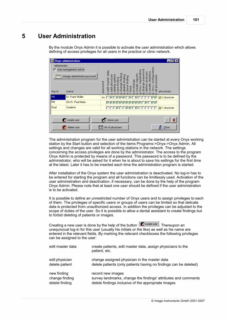
User Administration 101
© Image Instruments GmbH 2001-2007
5 User Administration
By the module Onyx Admin it is possible to activate the user administration which allowsdefining of access privileges for all users in the practice or clinic network.
The administration program for the user administration can be started at every Onyx workingstation by the Start button and selection of the items Programs->Onyx->Onyx Admin. Allsettings and changes are valid for all working stations in the network. The settingsconcerning the access privileges are done by the administrator. The access to the programOnyx Admin is protected by means of a password. This password is to be defined by theadministrator, who will be asked for it when he is about to save his settings for the first timeat the latest. Later it has to be inserted each time the administration program is started.
After installation of the Onyx system the user administration is deactivated. No log-in has tobe entered for starting the program and all functions can be limitlessly used. Activation of theuser administration and deactivation, if necessary, can be done by the help of the programOnyx Admin. Please note that at least one user should be defined if the user administrationis to be activated.
It is possible to define an unrestricted number of Onyx users and to assign privileges to eachof them. The privileges of specific users or groups of users can be limited so that delicatedata is protected from unauthorized access. In addition the privileges can be adjusted to thescope of duties of the user. So it is possible to allow a dental assistant to create findings butto forbid deleting of patients or images.
Creating a new user is done by the help of the button . Thereupon anunequivocal log-in for this user (usually his initials or the like) as well as his name areentered in the relevant fields. By marking the relevant checkboxes the following privilegescan be assigned to the user:
edit master data create patients, edit master data, assign physicians to thepatient, etc.
edit physician change assigned physician in the master data
delete patient delete patients (only patients having no findings can be deleted)
new finding record new images
change finding survey landmarks, change the findings' attributes and comments
delete finding delete findings inclusive of the appropriate images
User Administration 102
© Image Instruments GmbH 2001-2007
clone finding create copies of findings, mirror images and treatmentsimulations
print use all printing functions
exchange save findings in containers or load findings from there
create reports
Onyx registration call the registration program
change password change user password
define analyses use the program Onyx PVL
create statistics unused at present (create statistics by the help of the statisticstool which will be available soon)
Onyx configuration set the Onyx-System
all physicians access to all patients regardless of their physician
The gray checkboxes cannot be selected because your present Onyx licence status doesnot support these privileges.
In Onyx each patient can be assigned to one or more physicians. Please note that user andphysician do not have to be the same person. By means of the physician the relatedness ofa patient to specific organizational structures is defined. This can be simply the respectivephysician, but also a specific department or clinic. For every user it must be defined whichpatients he is allowed to access to. Selection of the physicians whose patients the usershould be allowed to access to is done after double-clicking on the relevant field. The usercan access to all patients that are assigned to at least one of the selected physicians. In theuser table only the number of physicians whose patients the user is allowed to access to isstated. It is possible to allow students to access to a group of example patients (only tothese patients), that has been assigned to a specific physician. By assigning more than onephysicians the administrator can organize different processes, such as substitutes forcolleagues on vacation, successors of colleagues, the superindentent's access to allpatients of his department, etc. in an easy way. The first, green colored item of the physiciantable is of special importance. This physician is assigned to each patient that is created bythe respective user. Patients having no physician are visible for all users.
Each user can define his own password for the access to the Onyx system. In the user list ofOnyx Admin this is illustrated by means of the small key in the column "password". If oneuser has forgotten his password the administrator can delete the old password bydouble-clicking on this key. After that the user can define his new password.
By the button a copy of an already defined user can be created. So the sameprivileges can be assigned to the new user.
The button permits maintenance of the list of physicians. Please note thatdeleting of physicians does not affect the patients' master data. There the assignedphysician is preserved although his item in the list of physicians has been deleted.
The arrow buttons adjust the sequence in the list of users. This sequence does not have anypractical meaning.
All changes will only be saved on closing the program Onyx Admin. Then you can decidewhether to save or to reject the changes.
Appendix 1: TreatmentSimulation

Appendix 1: Treatment Simulation 104
© Image Instruments GmbH 2001-2007
6 Appendix 1: Treatment Simulation
The evaluated findings can be handed over to the implemented planning option that permitstreatment simulation and visualization of possible treatment results by the help of the menupoint Extras|Treatment Simulation.
By the help of the two-dimensional image surgical or orthodontic treatment can be simulatedby segmentation, displacement and rotation of several user-defined areas.
For secondary points (e.g. soft tissue landmarks) calculation rules can be edited and storedin groups that describe their shift as function of the shift of the primary points (e.g. skeletallandmarks).The results of the selected analysis are transformed during the simulation and can be savedas modified finding in the patient's file card to permit comparison, superimposition, morphingand the use of further functions that are implemented in Onyx Ceph™.
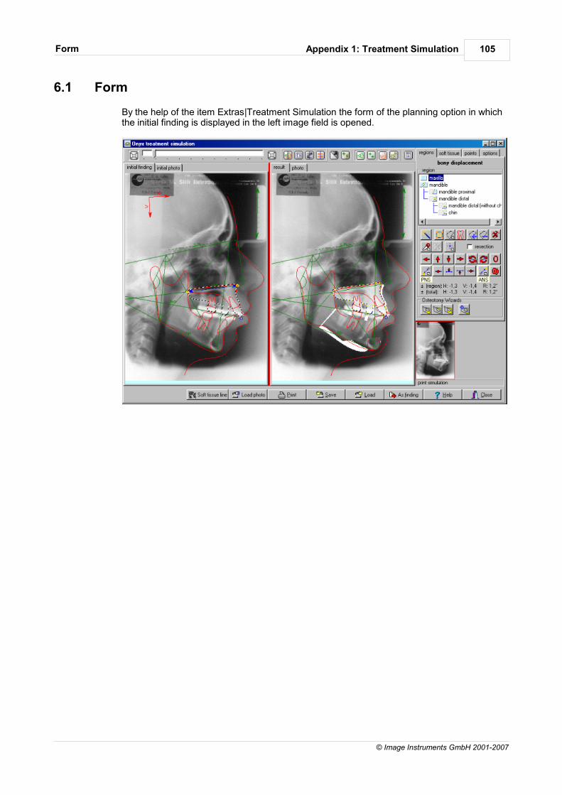
Appendix 1: Treatment SimulationForm 105
© Image Instruments GmbH 2001-2007
6.1 Form
By the help of the item Extras|Treatment Simulation the form of the planning option in whichthe initial finding is displayed in the left image field is opened.
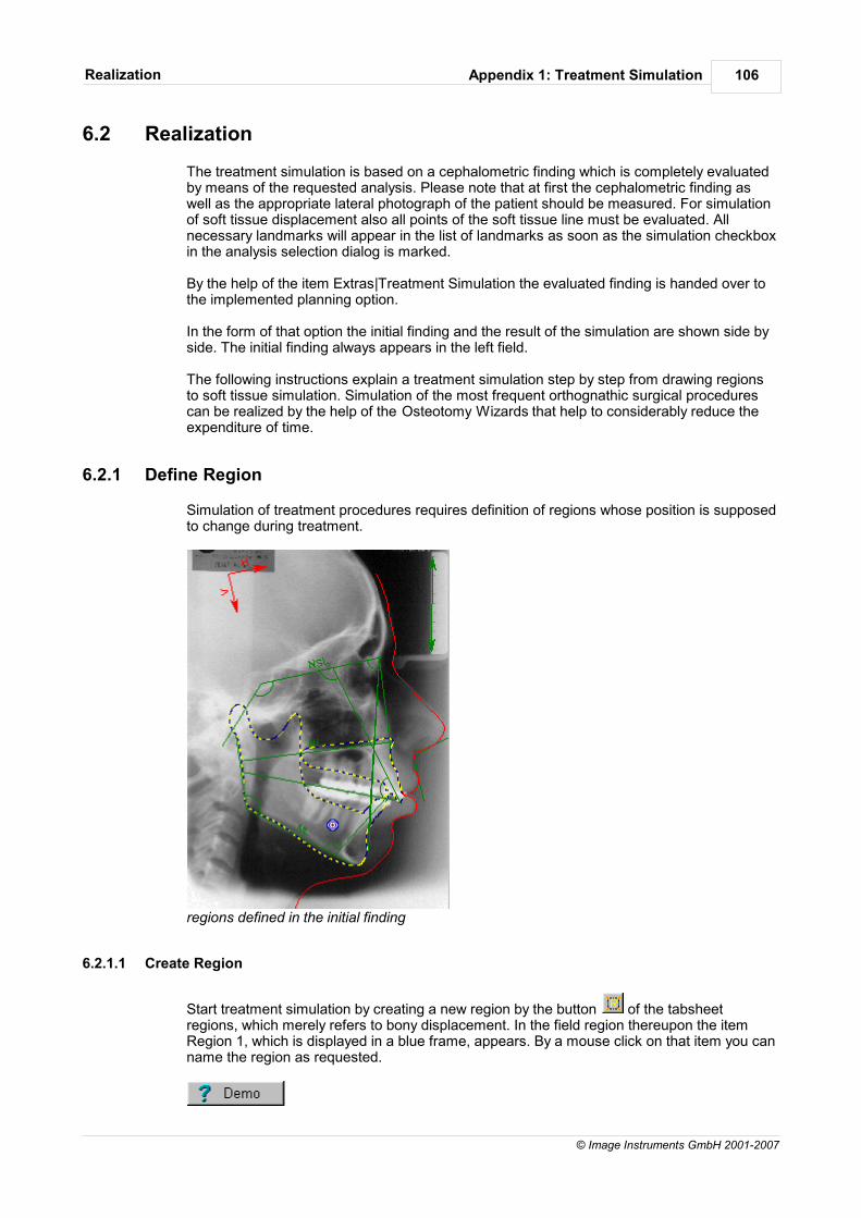
Appendix 1: Treatment SimulationRealization 106
© Image Instruments GmbH 2001-2007
6.2 Realization
The treatment simulation is based on a cephalometric finding which is completely evaluatedby means of the requested analysis. Please note that at first the cephalometric finding aswell as the appropriate lateral photograph of the patient should be measured. For simulationof soft tissue displacement also all points of the soft tissue line must be evaluated. Allnecessary landmarks will appear in the list of landmarks as soon as the simulation checkboxin the analysis selection dialog is marked.
By the help of the item Extras|Treatment Simulation the evaluated finding is handed over tothe implemented planning option.
In the form of that option the initial finding and the result of the simulation are shown side byside. The initial finding always appears in the left field.
The following instructions explain a treatment simulation step by step from drawing regionsto soft tissue simulation. Simulation of the most frequent orthognathic surgical procedurescan be realized by the help of the Osteotomy Wizards that help to considerably reduce theexpenditure of time.
6.2.1 Define Region
Simulation of treatment procedures requires definition of regions whose position is supposedto change during treatment.
regions defined in the initial finding
6.2.1.1 Create Region
Start treatment simulation by creating a new region by the button of the tabsheetregions, which merely refers to bony displacement. In the field region thereupon the itemRegion 1, which is displayed in a blue frame, appears. By a mouse click on that item you canname the region as requested.
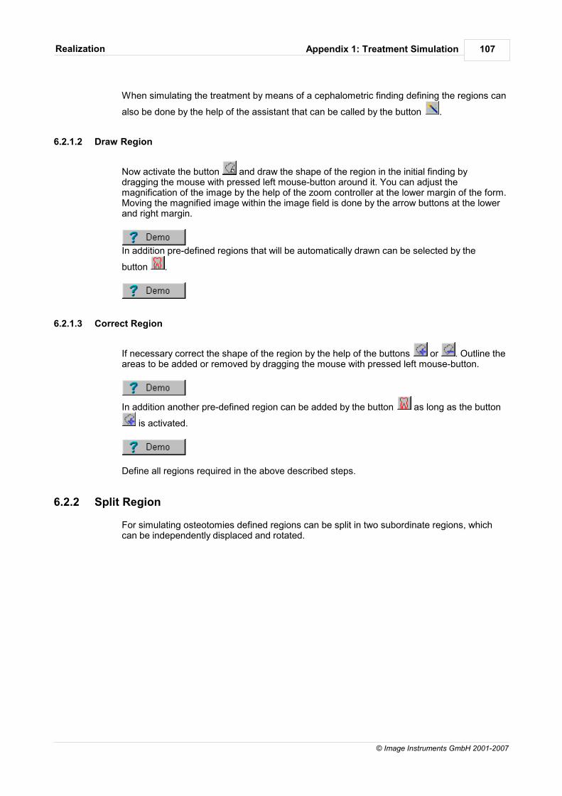
Appendix 1: Treatment SimulationRealization 107
© Image Instruments GmbH 2001-2007
When simulating the treatment by means of a cephalometric finding defining the regions can
also be done by the help of the assistant that can be called by the button .
6.2.1.2 Draw Region
Now activate the button and draw the shape of the region in the initial finding bydragging the mouse with pressed left mouse-button around it. You can adjust themagnification of the image by the help of the zoom controller at the lower margin of the form.Moving the magnified image within the image field is done by the arrow buttons at the lowerand right margin.
In addition pre-defined regions that will be automatically drawn can be selected by the
button .
6.2.1.3 Correct Region
If necessary correct the shape of the region by the help of the buttons or . Outline theareas to be added or removed by dragging the mouse with pressed left mouse-button.
In addition another pre-defined region can be added by the button as long as the button
is activated.
Define all regions required in the above described steps.
6.2.2 Split Region
For simulating osteotomies defined regions can be split in two subordinate regions, whichcan be independently displaced and rotated.
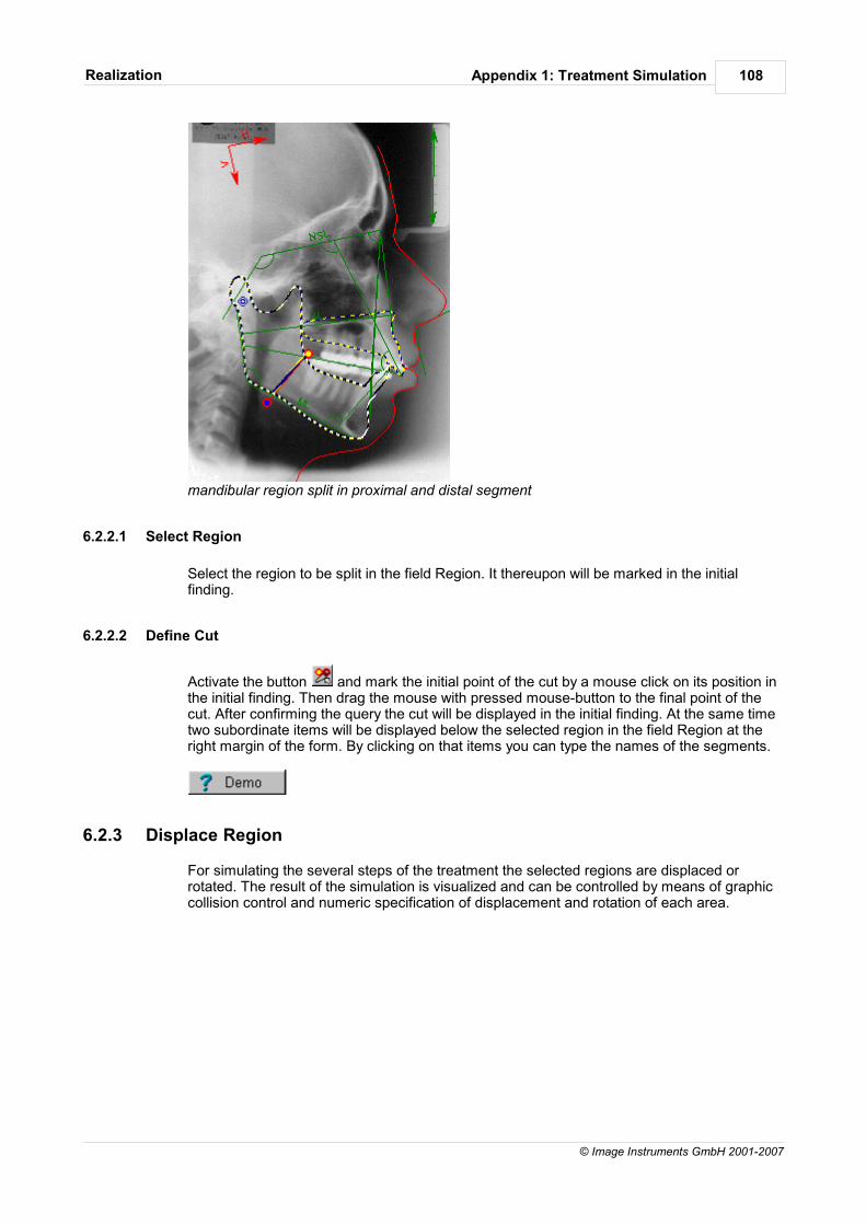
Appendix 1: Treatment SimulationRealization 108
© Image Instruments GmbH 2001-2007
mandibular region split in proximal and distal segment
6.2.2.1 Select Region
Select the region to be split in the field Region. It thereupon will be marked in the initialfinding.
6.2.2.2 Define Cut
Activate the button and mark the initial point of the cut by a mouse click on its position inthe initial finding. Then drag the mouse with pressed mouse-button to the final point of thecut. After confirming the query the cut will be displayed in the initial finding. At the same timetwo subordinate items will be displayed below the selected region in the field Region at theright margin of the form. By clicking on that items you can type the names of the segments.
6.2.3 Displace Region
For simulating the several steps of the treatment the selected regions are displaced orrotated. The result of the simulation is visualized and can be controlled by means of graphiccollision control and numeric specification of displacement and rotation of each area.
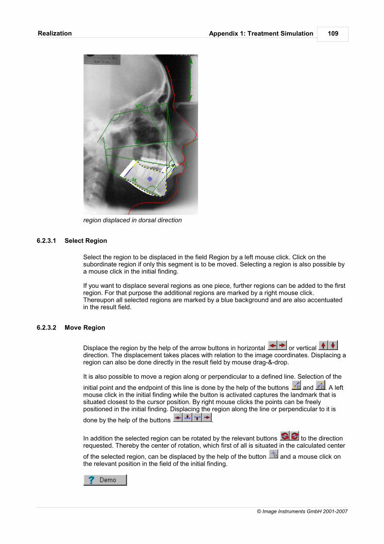
Appendix 1: Treatment SimulationRealization 109
© Image Instruments GmbH 2001-2007
region displaced in dorsal direction
6.2.3.1 Select Region
Select the region to be displaced in the field Region by a left mouse click. Click on thesubordinate region if only this segment is to be moved. Selecting a region is also possible bya mouse click in the initial finding.
If you want to displace several regions as one piece, further regions can be added to the firstregion. For that purpose the additional regions are marked by a right mouse click.Thereupon all selected regions are marked by a blue background and are also accentuatedin the result field.
6.2.3.2 Move Region
Displace the region by the help of the arrow buttons in horizontal or vertical direction. The displacement takes places with relation to the image coordinates. Displacing aregion can also be done directly in the result field by mouse drag-&-drop.
It is also possible to move a region along or perpendicular to a defined line. Selection of the
initial point and the endpoint of this line is done by the help of the buttons and . A leftmouse click in the initial finding while the button is activated captures the landmark that issituated closest to the cursor position. By right mouse clicks the points can be freelypositioned in the initial finding. Displacing the region along the line or perpendicular to it is
done by the help of the buttons .
In addition the selected region can be rotated by the relevant buttons to the directionrequested. Thereby the center of rotation, which first of all is situated in the calculated center
of the selected region, can be displaced by the help of the button and a mouse click onthe relevant position in the field of the initial finding.
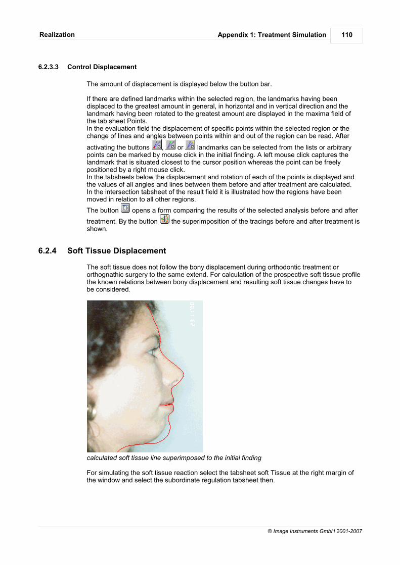
Appendix 1: Treatment SimulationRealization 110
© Image Instruments GmbH 2001-2007
6.2.3.3 Control Displacement
The amount of displacement is displayed below the button bar.
If there are defined landmarks within the selected region, the landmarks having beendisplaced to the greatest amount in general, in horizontal and in vertical direction and thelandmark having been rotated to the greatest amount are displayed in the maxima field ofthe tab sheet Points. In the evaluation field the displacement of specific points within the selected region or thechange of lines and angles between points within and out of the region can be read. After
activating the buttons , or landmarks can be selected from the lists or arbitrarypoints can be marked by mouse click in the initial finding. A left mouse click captures thelandmark that is situated closest to the cursor position whereas the point can be freelypositioned by a right mouse click.In the tabsheets below the displacement and rotation of each of the points is displayed andthe values of all angles and lines between them before and after treatment are calculated.In the intersection tabsheet of the result field it is illustrated how the regions have beenmoved in relation to all other regions.
The button opens a form comparing the results of the selected analysis before and after
treatment. By the button the superimposition of the tracings before and after treatment isshown.
6.2.4 Soft Tissue Displacement
The soft tissue does not follow the bony displacement during orthodontic treatment ororthognathic surgery to the same extend. For calculation of the prospective soft tissue profilethe known relations between bony displacement and resulting soft tissue changes have tobe considered.
calculated soft tissue line superimposed to the initial finding
For simulating the soft tissue reaction select the tabsheet soft Tissue at the right margin ofthe window and select the subordinate regulation tabsheet then.
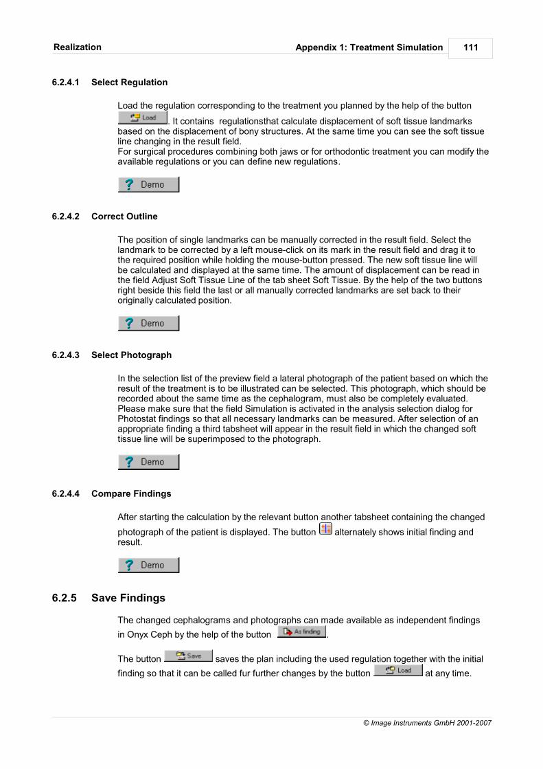
Appendix 1: Treatment SimulationRealization 111
© Image Instruments GmbH 2001-2007
6.2.4.1 Select Regulation
Load the regulation corresponding to the treatment you planned by the help of the button
. It contains regulationsthat calculate displacement of soft tissue landmarksbased on the displacement of bony structures. At the same time you can see the soft tissueline changing in the result field.For surgical procedures combining both jaws or for orthodontic treatment you can modify theavailable regulations or you can define new regulations.
6.2.4.2 Correct Outline
The position of single landmarks can be manually corrected in the result field. Select thelandmark to be corrected by a left mouse-click on its mark in the result field and drag it tothe required position while holding the mouse-button pressed. The new soft tissue line willbe calculated and displayed at the same time. The amount of displacement can be read inthe field Adjust Soft Tissue Line of the tab sheet Soft Tissue. By the help of the two buttonsright beside this field the last or all manually corrected landmarks are set back to theiroriginally calculated position.
6.2.4.3 Select Photograph
In the selection list of the preview field a lateral photograph of the patient based on which theresult of the treatment is to be illustrated can be selected. This photograph, which should berecorded about the same time as the cephalogram, must also be completely evaluated.Please make sure that the field Simulation is activated in the analysis selection dialog forPhotostat findings so that all necessary landmarks can be measured. After selection of anappropriate finding a third tabsheet will appear in the result field in which the changed softtissue line will be superimposed to the photograph.
6.2.4.4 Compare Findings
After starting the calculation by the relevant button another tabsheet containing the changed
photograph of the patient is displayed. The button alternately shows initial finding andresult.
6.2.5 Save Findings
The changed cephalograms and photographs can made available as independent findings
in Onyx Ceph by the help of the button .
The button saves the plan including the used regulation together with the initial
finding so that it can be called fur further changes by the button at any time.

Appendix 2: RickettsVTO
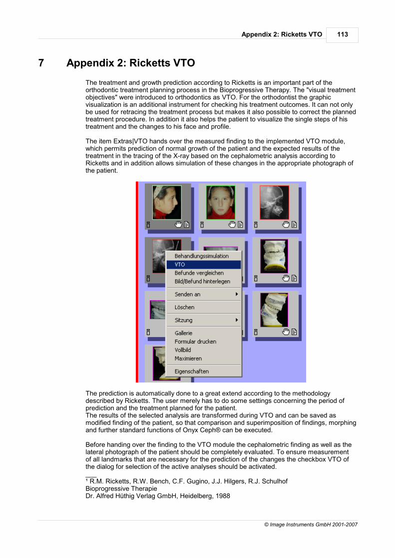
Appendix 2: Ricketts VTO 113
© Image Instruments GmbH 2001-2007
7 Appendix 2: Ricketts VTO
The treatment and growth prediction according to Ricketts is an important part of theorthodontic treatment planning process in the Bioprogressive Therapy. The "visual treatmentobjectives" were introduced to orthodontics as VTO. For the orthodontist the graphicvisualization is an additional instrument for checking his treatment outcomes. It can not onlybe used for retracing the treatment process but makes it also possible to correct the plannedtreatment procedure. In addition it also helps the patient to visualize the single steps of histreatment and the changes to his face and profile.
The item Extras|VTO hands over the measured finding to the implemented VTO module,which permits prediction of normal growth of the patient and the expected results of thetreatment in the tracing of the X-ray based on the cephalometric analysis according toRicketts and in addition allows simulation of these changes in the appropriate photograph ofthe patient.
The prediction is automatically done to a great extend according to the methodologydescribed by Ricketts. The user merely has to do some settings concerning the period ofprediction and the treatment planned for the patient.The results of the selected analysis are transformed during VTO and can be saved asmodified finding of the patient, so that comparison and superimposition of findings, morphingand further standard functions of Onyx Ceph® can be executed.
Before handing over the finding to the VTO module the cephalometric finding as well as thelateral photograph of the patient should be completely evaluated. To ensure measurementof all landmarks that are necessary for the prediction of the changes the checkbox VTO ofthe dialog for selection of the active analyses should be activated.___¹ R.M. Ricketts, R.W. Bench, C.F. Gugino, J.J. Hilgers, R.J. SchulhofBioprogressive TherapieDr. Alfred Hüthig Verlag GmbH, Heidelberg, 1988

Appendix 2: Ricketts VTO 114
© Image Instruments GmbH 2001-2007
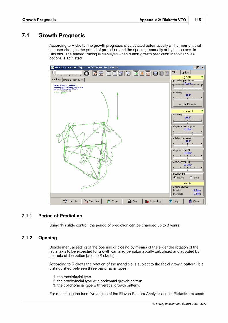
Appendix 2: Ricketts VTOGrowth Prognosis 115
© Image Instruments GmbH 2001-2007
7.1 Growth Prognosis
According to Ricketts, the growth prognosis is calculated automatically at the moment thatthe user changes the period of prediction and the opening manually or by button acc. toRicketts. The related tracing is displayed when button growth prediction in toolbar Viewoptions is activated.
7.1.1 Period of Prediction
Using this slide control, the period of prediction can be changed up to 3 years.
7.1.2 Opening
Beside manual setting of the opening or closing by means of the slider the rotation of thefacial axis to be expected for growth can also be automatically calculated and adopted bythe help of the button [acc. to Ricketts]..
According to Ricketts the rotation of the mandible is subject to the facial growth pattern. It isdistinguished between three basic facial types:
1. the mesiofacial type2. the brachyfacial type with horizontal growth pattern3. the dolichofacial type with vertical growth pattern.
For describing the face five angles of the Eleven-Factors-Analysis acc. to Ricketts are used:
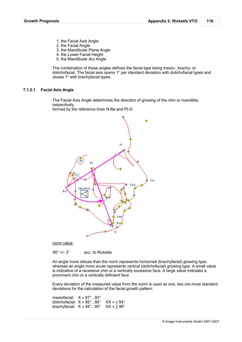
Appendix 2: Ricketts VTOGrowth Prognosis 116
© Image Instruments GmbH 2001-2007
1. the Facial Axis Angle2. the Facial Angle3. the Mandibular Plane Angle4. the Lower Facial Height5. the Mandibular Arc Angle
The combination of these angles defines the facial type being mesio-, brachy- ordolichofacial. The facial axis opens 1° per standard deviation with dolichofacial types andcloses 1° with brachyfacial types.
7.1.2.1 Facial Axis Angle
The Facial Axis Angle determines the direction of growing of the chin or mandible,respectively. formed by the reference lines N-Ba and Pt-G
norm value:
90° +/- 3° acc. to Ricketts
An angle more obtuse than the norm represents horizontal (brachyfacial) growing type,whereas an angle more acute represents vertical (dolichofacial) growing type. A small valueis indicative of a recessive chin or a vertically excessive face. A large value indicates aprominent chin or a vertically deficient face.
Every deviation of the measured value from the norm is used as one, two ore more standarddeviations for the calculation of the facial growth pattern.
mesiofacial: X » 87°...93°dolichofacial: X » 85°...86° XX » < 84°brachyfacial: X » 94°...95° XX » > 96°
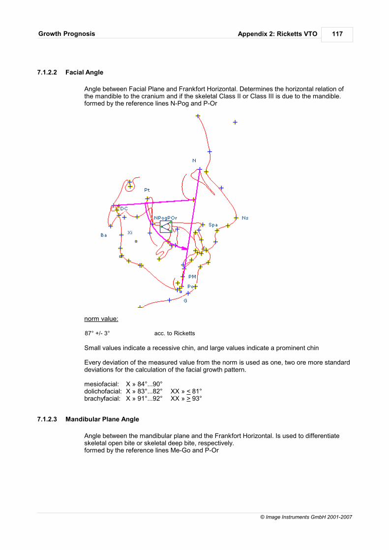
Appendix 2: Ricketts VTOGrowth Prognosis 117
© Image Instruments GmbH 2001-2007
7.1.2.2 Facial Angle
Angle between Facial Plane and Frankfort Horizontal. Determines the horizontal relation ofthe mandible to the cranium and if the skeletal Class II or Class III is due to the mandible.formed by the reference lines N-Pog and P-Or
norm value:
87° +/- 3° acc. to Ricketts
Small values indicate a recessive chin, and large values indicate a prominent chin
Every deviation of the measured value from the norm is used as one, two ore more standarddeviations for the calculation of the facial growth pattern.
mesiofacial: X » 84°...90°dolichofacial: X » 83°...82° XX » < 81°brachyfacial: X » 91°...92° XX » > 93°
7.1.2.3 Mandibular Plane Angle
Angle between the mandibular plane and the Frankfort Horizontal. Is used to differentiateskeletal open bite or skeletal deep bite, respectively.formed by the reference lines Me-Go and P-Or
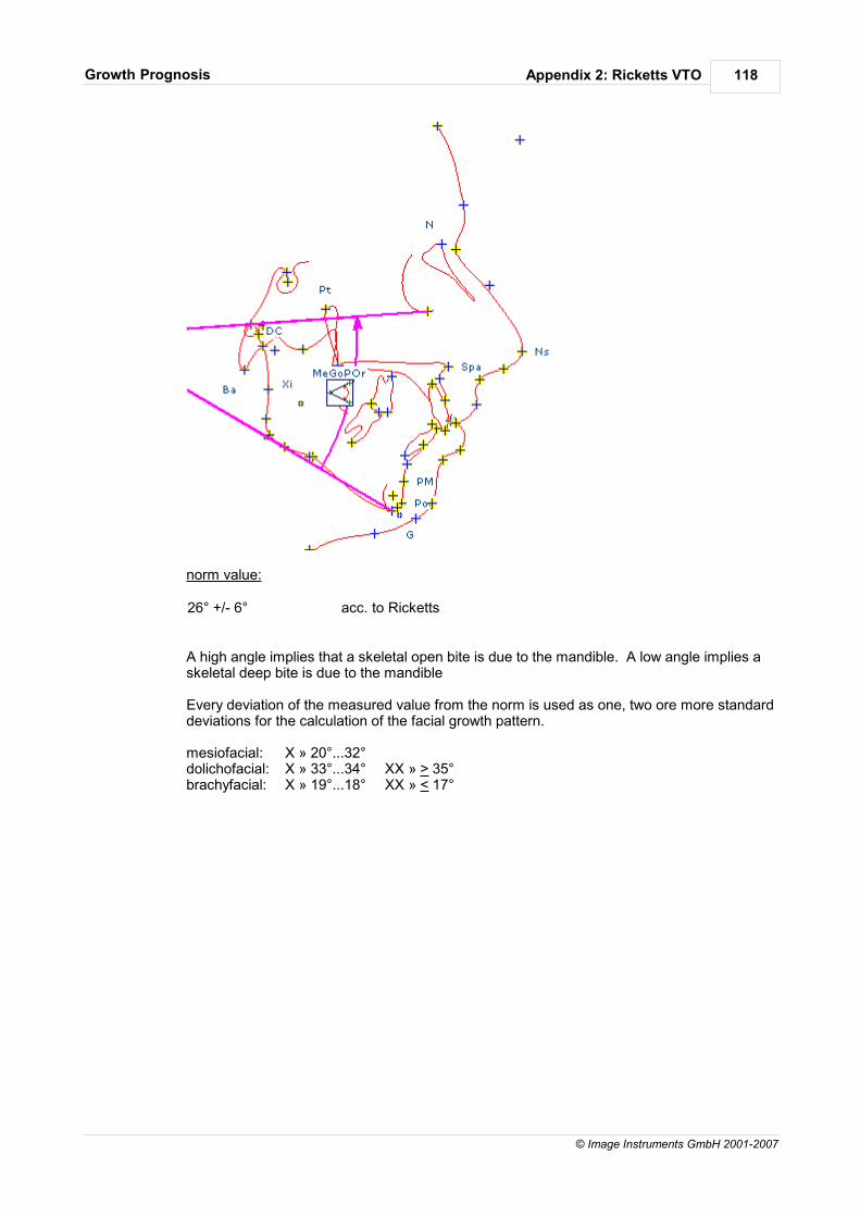
Appendix 2: Ricketts VTOGrowth Prognosis 118
© Image Instruments GmbH 2001-2007
norm value:
26° +/- 6° acc. to Ricketts
A high angle implies that a skeletal open bite is due to the mandible. A low angle implies askeletal deep bite is due to the mandible
Every deviation of the measured value from the norm is used as one, two ore more standarddeviations for the calculation of the facial growth pattern.
mesiofacial: X » 20°...32°dolichofacial: X » 33°...34° XX » > 35°brachyfacial: X » 19°...18° XX » < 17°
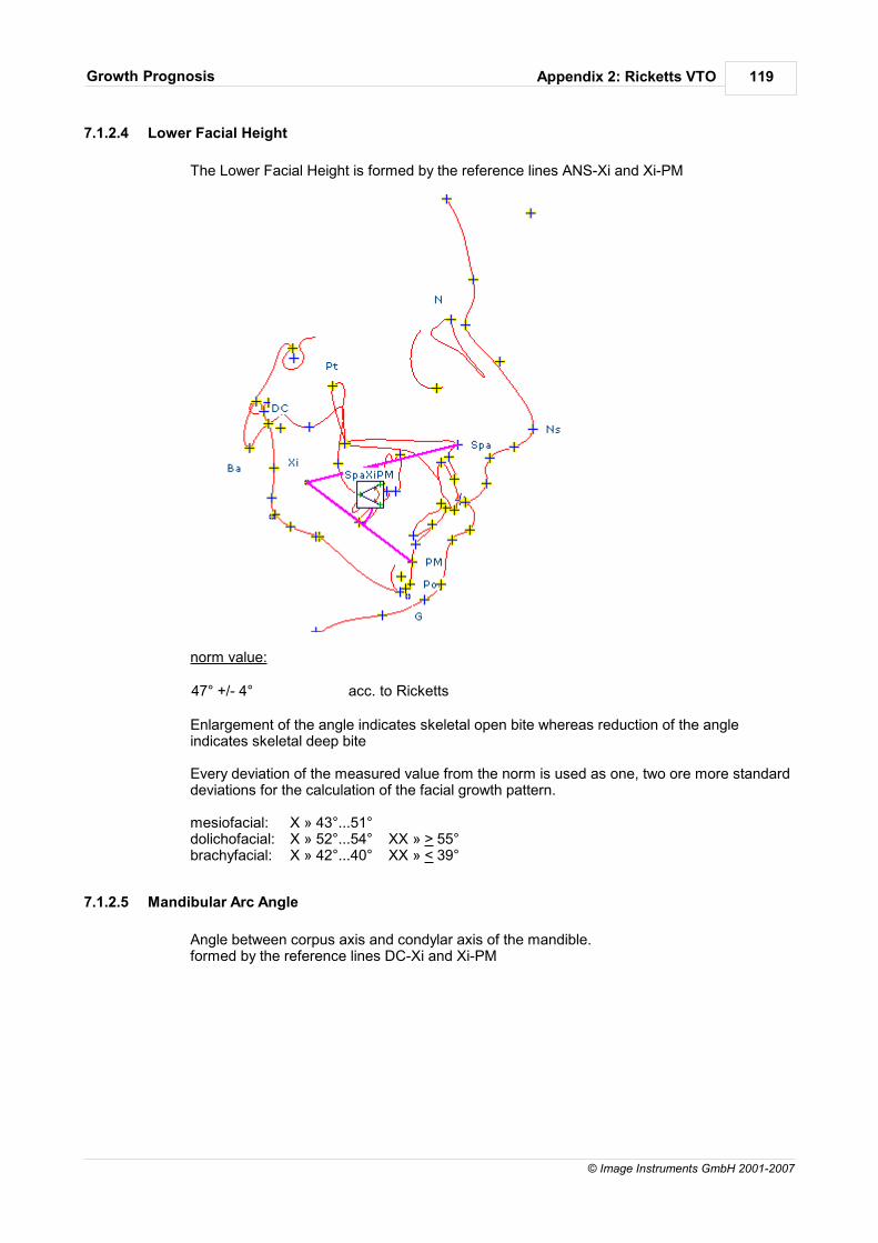
Appendix 2: Ricketts VTOGrowth Prognosis 119
© Image Instruments GmbH 2001-2007
7.1.2.4 Lower Facial Height
The Lower Facial Height is formed by the reference lines ANS-Xi and Xi-PM
norm value:
47° +/- 4° acc. to Ricketts
Enlargement of the angle indicates skeletal open bite whereas reduction of the angleindicates skeletal deep bite
Every deviation of the measured value from the norm is used as one, two ore more standarddeviations for the calculation of the facial growth pattern.
mesiofacial: X » 43°...51°dolichofacial: X » 52°...54° XX » > 55°brachyfacial: X » 42°...40° XX » < 39°
7.1.2.5 Mandibular Arc Angle
Angle between corpus axis and condylar axis of the mandible. formed by the reference lines DC-Xi and Xi-PM
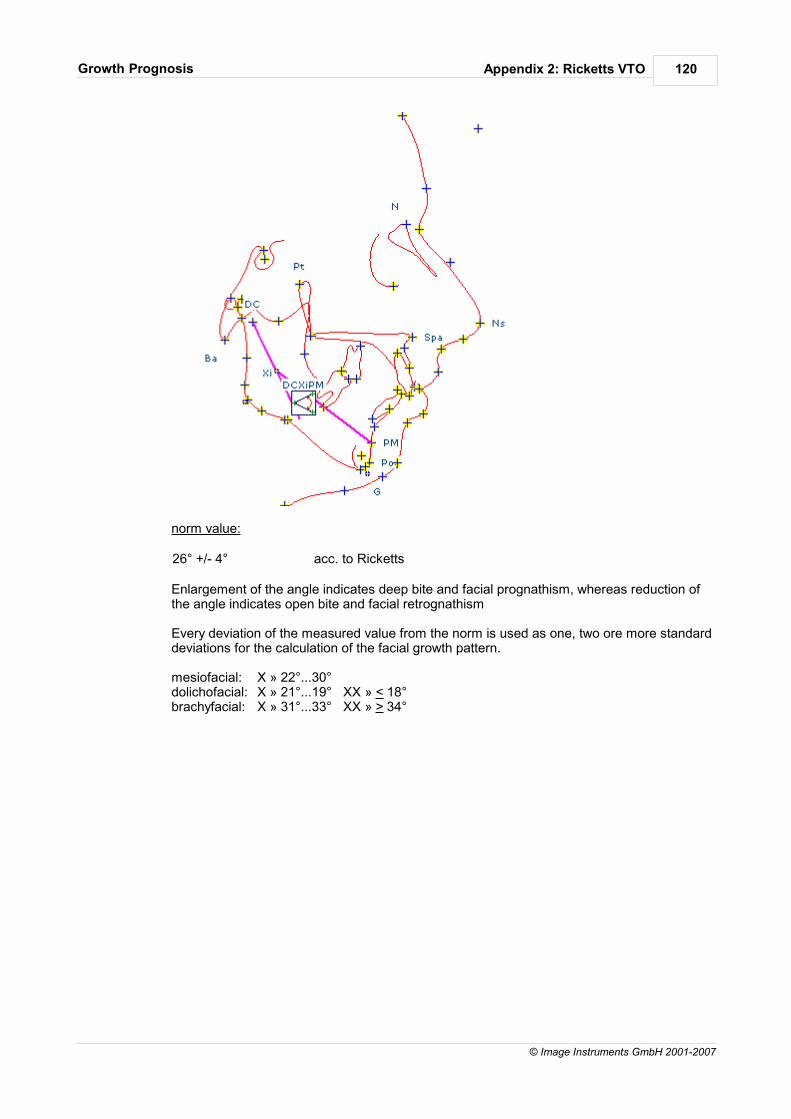
Appendix 2: Ricketts VTOGrowth Prognosis 120
© Image Instruments GmbH 2001-2007
norm value:
26° +/- 4° acc. to Ricketts
Enlargement of the angle indicates deep bite and facial prognathism, whereas reduction ofthe angle indicates open bite and facial retrognathism
Every deviation of the measured value from the norm is used as one, two ore more standarddeviations for the calculation of the facial growth pattern.
mesiofacial: X » 22°...30°dolichofacial: X » 21°...19° XX » < 18°brachyfacial: X » 31°...33° XX » > 34°
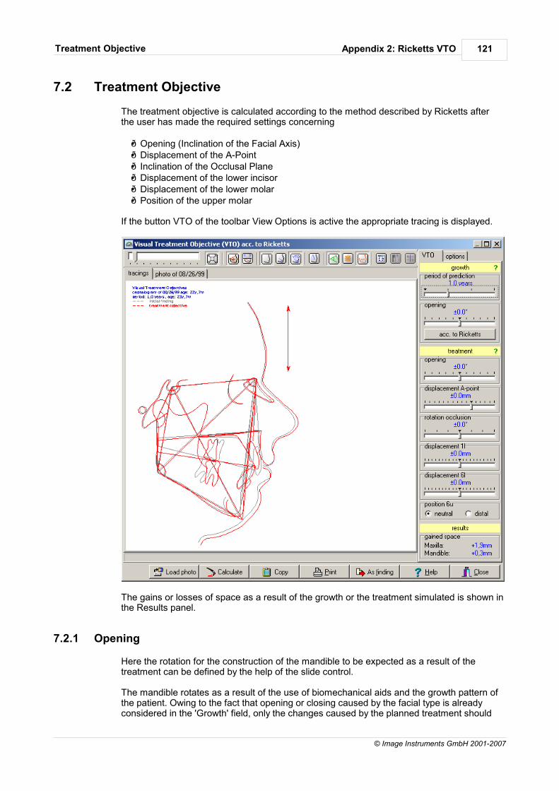
Appendix 2: Ricketts VTOTreatment Objective 121
© Image Instruments GmbH 2001-2007
7.2 Treatment Objective
The treatment objective is calculated according to the method described by Ricketts afterthe user has made the required settings concerning
Opening (Inclination of the Facial Axis) Displacement of the A-Point Inclination of the Occlusal Plane Displacement of the lower incisor Displacement of the lower molar Position of the upper molar
If the button VTO of the toolbar View Options is active the appropriate tracing is displayed.
The gains or losses of space as a result of the growth or the treatment simulated is shown inthe Results panel.
7.2.1 Opening
Here the rotation for the construction of the mandible to be expected as a result of thetreatment can be defined by the help of the slide control.
The mandible rotates as a result of the use of biomechanical aids and the growth pattern ofthe patient. Owing to the fact that opening or closing caused by the facial type is alreadyconsidered in the 'Growth' field, only the changes caused by the planned treatment should
Appendix 2: Ricketts VTOTreatment Objective 122
© Image Instruments GmbH 2001-2007
be set here.
The average effect to the rotation of the mandible is the following:
a) The facial axis may open during treatmentb) The facial axis may close as a result of extractions or the use of theHigh-pull-Headgear
Thereby the following biomechanical effects can occur:- During reduction of the convexity the facial axis opens 1° per 5mm - During correction of the molars the facial axis opens 1° per 4mm - During correction of the vertical overbite the facial axis opens 1° per 4mm- During elimination of the cross bite the facial axis opens 1-1,5°. After adaptation it closeshalf the amount again.
7.2.2 Displacement A-Point
The position of the A point changes as a result of the biomechanical influences. Below themaximum changes during the use of different biomechanical aids are mentioned:
Headgear 8mmClass-II-Elastics -3mmActivator 2mmPalatinal root torque -1...-2mmClass-III-Elastics +2...+3mmFace mask +3...+4mm
The changes to the A point to be expected can be defined by the help of the slider. For eachmillimeter of dorsal movement the A point will move cranially half a millimeter.
7.2.3 Rotation Occlusal Plane
By the help of this button the changes to the inclination of the occlusal plane are defined.This change can amount up to 3° in the one or the other direction as a result of Class II orClass III treatment.
7.2.4 Displacement 1l
The program puts the lower molar in an ideal position in relation to the symphysis of themandible, to the occlusal plane and to the A-Pog plane. Its exact position is to bedetermined by the required arch length and by the realistic idea of the treatment results to beachieved.
In a position of 1mm in front of the A-Pog line and 1mm above the occlusal plane the angleshould be 22°. This angle is to be increased 2° as compromise for each millimeter theincisor is inclined to the front in order to achieve the arch length required.
By the help of the slider it is defined to what extend the incisor is to be moved forward orbackward. The inclination then is automatically corrected.
7.2.5 Displacement 6l
The displacement of the lower first molar depends on the arch length required. The programlets the tooth erupt vertically on the occlusal plane and automatically uprights it. If treatmentis applied 1mm distal molar displacement corresponds to an arch length of 2mm. Thenecessary anterior or posterior displacement that depends on the space requirements isdefined by the help of the slider. The space gained or lost as a result of the molar movement

Appendix 2: Ricketts VTOTreatment Objective 123
© Image Instruments GmbH 2001-2007
is stated in the field Results.
7.2.6 Position 6u
Here it is defined if the upper molar is to be placed against the lower molar in a neutral ordistal position. The space gained or lost in the upper jaw is stated in the field Results.
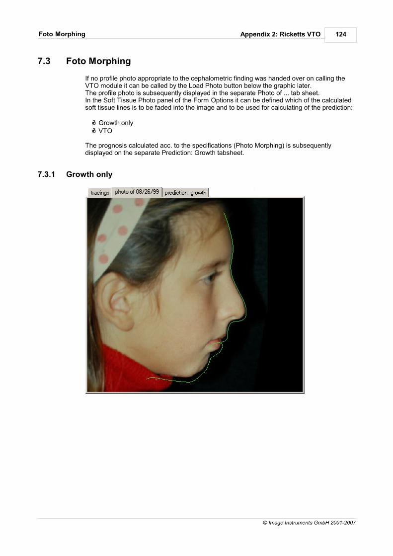
Appendix 2: Ricketts VTOFoto Morphing 124
© Image Instruments GmbH 2001-2007
7.3 Foto Morphing
If no profile photo appropriate to the cephalometric finding was handed over on calling theVTO module it can be called by the Load Photo button below the graphic later.The profile photo is subsequently displayed in the separate Photo of ... tab sheet. In the Soft Tissue Photo panel of the Form Options it can be defined which of the calculatedsoft tissue lines is to be faded into the image and to be used for calculating of the prediction:
Growth only VTO
The prognosis calculated acc. to the specifications (Photo Morphing) is subsequentlydisplayed on the separate Prediction: Growth tabsheet.
7.3.1 Growth only
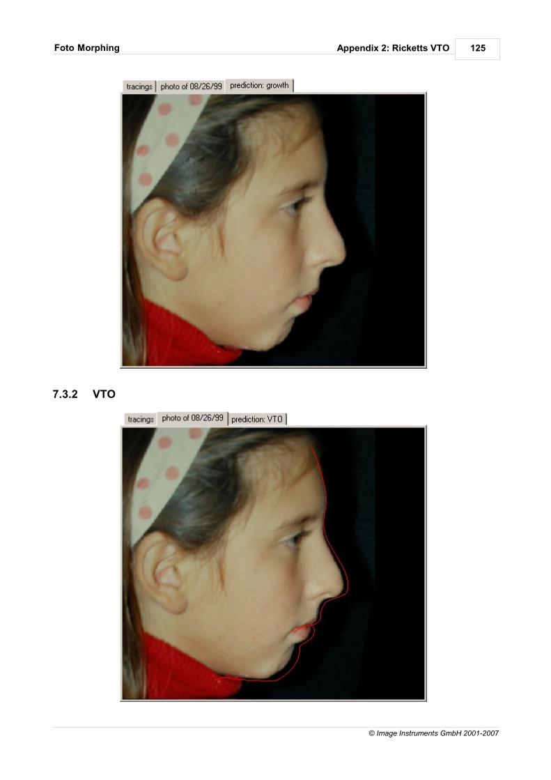
Appendix 2: Ricketts VTOFoto Morphing 125
© Image Instruments GmbH 2001-2007
7.3.2 VTO
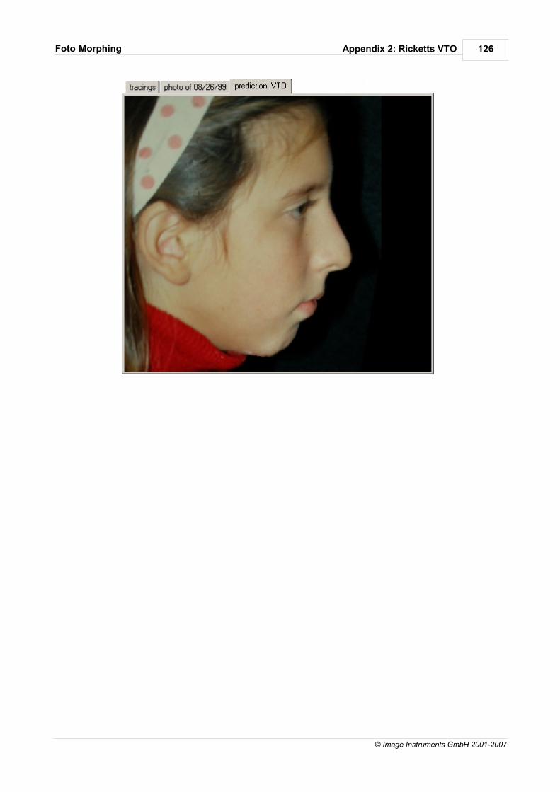
Appendix 2: Ricketts VTOFoto Morphing 126
© Image Instruments GmbH 2001-2007
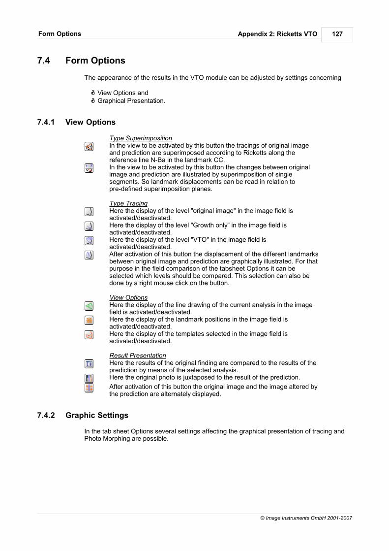
Appendix 2: Ricketts VTOForm Options 127
© Image Instruments GmbH 2001-2007
7.4 Form Options
The appearance of the results in the VTO module can be adjusted by settings concerning
View Options and Graphical Presentation.
7.4.1 View Options
Type SuperimpositionIn the view to be activated by this button the tracings of original imageand prediction are superimposed according to Ricketts along thereference line N-Ba in the landmark CC.In the view to be activated by this button the changes between originalimage and prediction are illustrated by superimposition of singlesegments. So landmark displacements can be read in relation topre-defined superimposition planes.
Type TracingHere the display of the level "original image" in the image field isactivated/deactivated.Here the display of the level "Growth only" in the image field isactivated/deactivated.Here the display of the level "VTO" in the image field isactivated/deactivated.After activation of this button the displacement of the different landmarksbetween original image and prediction are graphically illustrated. For thatpurpose in the field comparison of the tabsheet Options it can beselected which levels should be compared. This selection can also bedone by a right mouse click on the button.
View OptionsHere the display of the line drawing of the current analysis in the imagefield is activated/deactivated.Here the display of the landmark positions in the image field isactivated/deactivated.Here the display of the templates selected in the image field isactivated/deactivated.
Result PresentationHere the results of the original finding are compared to the results of theprediction by means of the selected analysis.Here the original photo is juxtaposed to the result of the prediction.
After activation of this button the original image and the image altered bythe prediction are alternately displayed.
7.4.2 Graphic Settings
In the tab sheet Options several settings affecting the graphical presentation of tracing andPhoto Morphing are possible.
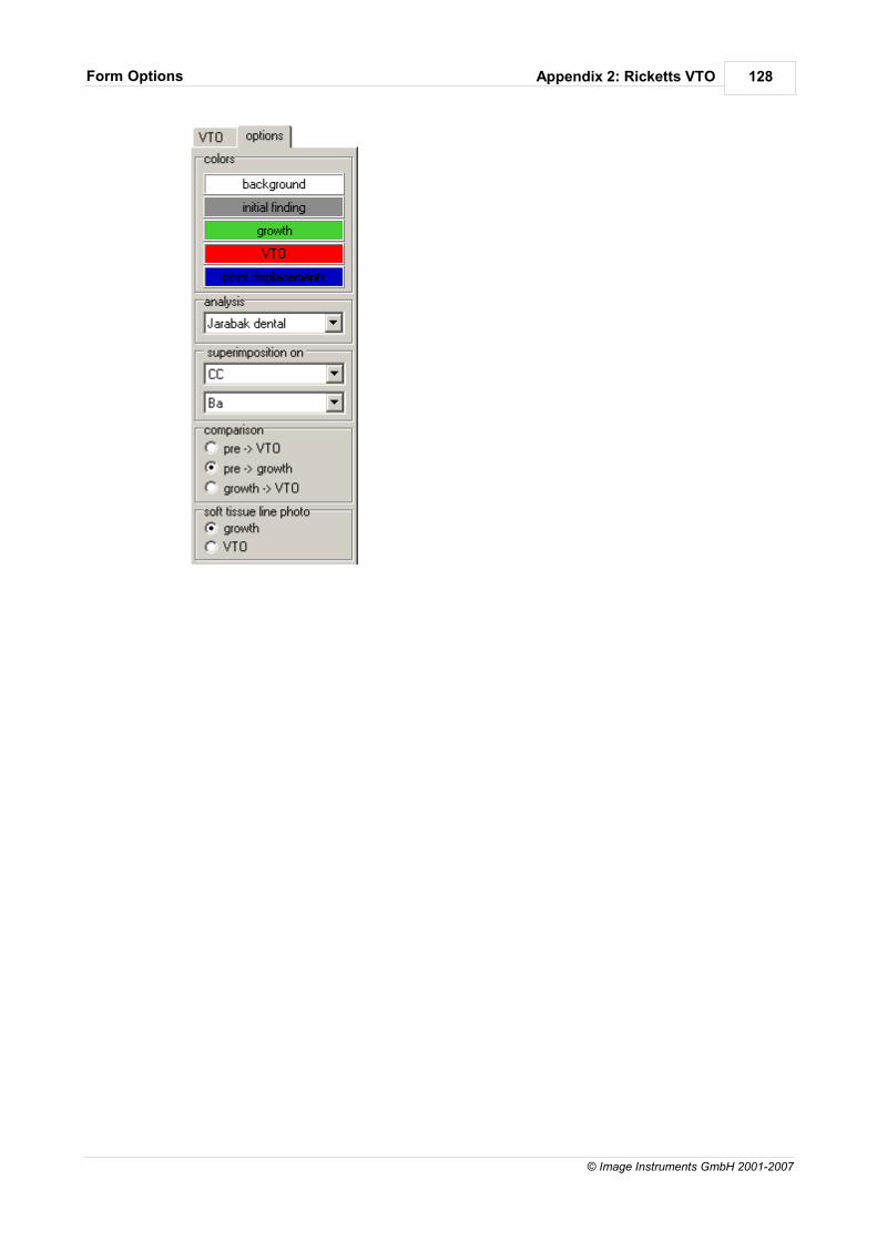
Appendix 2: Ricketts VTOForm Options 128
© Image Instruments GmbH 2001-2007
Appendix 3: ImageProcessing Tools
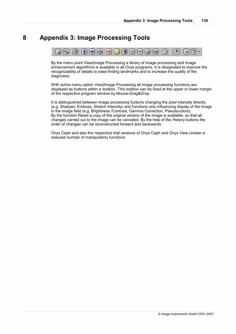
Appendix 3: Image Processing Tools 130
© Image Instruments GmbH 2001-2007
8 Appendix 3: Image Processing Tools
By the menu point View|Image Processing a library of image processing and imageenhancement algorithms is available in all Onyx programs. It is designated to improve therecognizability of details to ease finding landmarks and to increase the quality of thediagnoses.
With active menu option View|Image Processing all image processing functions aredisplayed as buttons within a toolbox. This toolbox can be fixed at the upper or lower marginof the respective program window by Mouse-Drag&Drop.
It is distinguished between image processing fuctions changing the pixel intensity directly(e.g. Sharpen, Emboss, Stretch Intensity) and functions only influencing display of the imagein the image field (e.g. Brightness /Contrast, Gamma Correction, Pseudocolors).By the function Reset a copy of the original version of the image is available, so that allchanges carried out to the image can be canceled. By the help of the History buttons theorder of changes can be reconstructed forward and backwards.
Onyx Ceph and also the respective trial versions of Onyx Ceph and Onyx View contain areduced number of manipulatory functions.

Appendix 3: Image Processing ToolsMouse Controller 131
© Image Instruments GmbH 2001-2007
8.1 Mouse Controller
The mouse Controller determines the function of the mouse.
Inactive Mouse Controller: With deactivated mouse controller the displayed section can be shifted within the image fieldby moving the mouse with pressed left button. In the status bar of Onyx View the absoluteshift of the image in horizontal and vertical direction is displayed. This function will only be available if zoom-settings cause the image lying partly beyond theimage field.
Active Mouse Controller:With activated mouse controller brightness and contrast of the current display can bechanged by moving the mouse across the image field. Brightness is changed by moving themouse with pressed left button in vertical direction. Minimum brightness appears with themouse pointer at the upper margin of the image field. It increases by moving the mousepointer to the lower margin. Moving in horizontal direction results in changing the contrast.Thereby contrast increases with moving from the right to the left margin.This function is used for improvement of recognizability of certain details. It always affectsthe current display. Another mouse click results in resetting of brightness and contrast to theinitial values.The changed settings for brightness and contrast maintain after using the magnifying glassor changing the zoom settings.The current percentage values for brightness and contrast are displayed in the status bar ofOnyx View.

Appendix 3: Image Processing ToolsMagnifying Glass 132
© Image Instruments GmbH 2001-2007
8.2 Magnifying Glass
By activating the magnifying glass the mouse pointer changes with pressed left button to amagnifier. The area around the mouse pointer is magnified. The size of the magnifier can bedefined in the tabsheet Magnifying Glass of the option Image Processing.
Contrast and brightness settings maintain while using the function Magnifying Glass.
Settings concerning the size and the magnification and contrast spreading within themagnifying glass can be done in the relevant tabsheet of the item Options|Image Processingor in the dialog which can be called by a right mouse click on the magnifying glass in thetoolbar.

Appendix 3: Image Processing ToolsCopy 133
© Image Instruments GmbH 2001-2007
8.3 Copy
By Mouse-Drag&Drop a section of the current image can be taken to the clipboard. This isdone in the color resolution of the graphics card preset by the operating system. In the tabsheet Copy of the item Options|Image Processing or in the dialog which can becalled by a right mouse click on the icon of the toolbar the shape for defining the clip can beselected.

Appendix 3: Image Processing ToolsPseudo Colors 134
© Image Instruments GmbH 2001-2007
8.4 Pseudo Colors
By the function Pseudocolors a gray scale image is converted to a color image. Each graypixel is substituted by a pixel with equivalent red, green and blue values. The colors tosubstitute the gray values can be defined by the help of the option Paint Palette.
Selection of the colors by which the gray values should be replaced is done in the dialogwhich can be called by a right mouse click on the icon of the toolbar.

Appendix 3: Image Processing ToolsFlip 135
© Image Instruments GmbH 2001-2007
8.5 Flip
By the help of this function the bitmap is flipped from top to bottom.

Appendix 3: Image Processing ToolsMirror 136
© Image Instruments GmbH 2001-2007
8.6 Mirror
By the function mirror the image is reversed as if it was mirrored from right to left.

Appendix 3: Image Processing ToolsRotate 137
© Image Instruments GmbH 2001-2007
8.7 Rotate
By this button the image can be rotated. The function required (90° right, 90° left, 180°,any)is selected from the pull-down-menu. The result of rotation is fit in the initial size of theimage.

Appendix 3: Image Processing ToolsHistogram Equalization 138
© Image Instruments GmbH 2001-2007
8.8 Histogram Equalization
Linearizes the number of pixels per gray level in the bitmap. This can be used to bring outthe details in dark areas of an image.
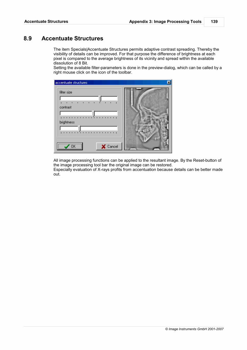
Appendix 3: Image Processing ToolsAccentuate Structures 139
© Image Instruments GmbH 2001-2007
8.9 Accentuate Structures
The item Specials|Accentuate Structures permits adaptive contrast spreading. Thereby thevisibility of details can be improved. For that purpose the difference of brightness at eachpixel is compared to the average brightness of its vicinity and spread within the availabledissolution of 8 Bit.Setting the available filter-parameters is done in the preview-dialog, which can be called by aright mouse click on the icon of the toolbar.
All image processing functions can be applied to the resultant image. By the Reset-button ofthe image processing tool bar the original image can be restored.Especially evaluation of X-rays profits from accentuation because details can be better madeout.

Appendix 3: Image Processing ToolsGamma Correction 140
© Image Instruments GmbH 2001-2007
8.10 Gamma Correction
Gamma is the value for contrast in the median gray scales of an image. The functionGamma Correction increases the brightness of an image without changing the brighter ordarker areas significantly. The Gamma value is the exponent for changing the pixel valuesof an image. The higher the value the brighter the image appears. The usual standard valuefor RGB-monitors is 2,2.
Defining the Gamma value is done by the help of the appropriate dialogs which can becalled by a right mouse click on the icon of the toolbar or by the dialog button in the tabsheetMode of the option Image Processing.

Appendix 3: Image Processing ToolsInvert 141
© Image Instruments GmbH 2001-2007
8.11 Invert
By this function the colors of the image are inverted to the complementary colors, making itlike a photographic negative.

Appendix 3: Image Processing ToolsAverage Filter 142
© Image Instruments GmbH 2001-2007
8.12 Average Filter
The Average Filter changes the color of each pixel in the bitmap to the average color of thepixels in its neighborhood. This results in a blur effect.
You control the amount of blur by specifying the size of the neighborhood that is used foraveraging.
Setting the frame size is done by the help of the appropriate dialogs which can be called by aright mouse click on the icon of the toolbar or by the dialog button in the tabsheet Mode ofthe option Image Processing.

Appendix 3: Image Processing ToolsSharpen 143
© Image Instruments GmbH 2001-2007
8.13 Sharpen
The effect Sharpen increases or decreases the sharpness of the image. The margins of thebitmap are accentuated or blurred. For this purpose the margins are localized and then thecontrast between the adjacent pixels is increased or reduced. The possible values arebetween –1000 and +1000. The value 0 does not affect the image. Negative values reducesharpness whereas positive values increase sharpness.
Setting the wanted value is done by the help of the appropriate dialogs which can be calledby a right mouse click on the icon of the toolbar or by the dialog button in the tabsheet Modeof the option Image Processing.

Appendix 3: Image Processing ToolsEmboss 144
© Image Instruments GmbH 2001-2007
8.14 Emboss
This function applies an emboss effect to the bitmap. Depth and direction of the effect canbe defined. This is realized in the relevant dialogs which can be called by a right mouse clickon the icon of the toolbar or by the dialog button in the tabsheet Mode of the option ImageProcessing.

Appendix 3: Image Processing ToolsReset 145
© Image Instruments GmbH 2001-2007
8.15 Reset
By the help of the function Reset all changes carried out to the image can be canceled. Forthis purpose a copy of the original image is loaded. The order of changes available by the History buttons is deleted.

Onyx Ceph™ Software develpment:
Image Instruments GmbHOlbernhauer Str. 5D 09125 ChemnitzGermanyPhone +49 371 9093 140Fax +49 371 9093 149Email [email protected]