Embed Size (px)
Citation preview

Op Amps
Op Amps
Real and Ideal Op AmpsWorking with real op ampsAmplifiersApplicationsStages and Cascading
Carruthers (ECE @ BU) EK307 Notes Spring 2020 81 / 275
Op Amps Real and Ideal Op Amps
Operational Amplifier
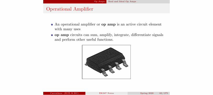
An operational amplifier or op amp is an active circuit elementwith many uses
op amp circuits can sum, amplify, integrate, di↵erentiate signalsand perform other useful functions.
Carruthers (ECE @ BU) EK307 Notes Spring 2020 82 / 275
Op Amps Real and Ideal Op Amps
Modeling an Op Amp
1 Ideal Most of the time, op amps are considered to be ideal. Thisis a simple yet accurate description of how a correctly configuredop amp works.
2 VCVS Circuit Model We can use this model to explain why theideal op amp functions the way it does. It also describes “howgood” a particular op amp is.
3 Transistors The actual circuit for an op amp consists of anumber of transistors. This full description can be approximatedby the VCVS circuit model.
Lets examine each of these.
Carruthers (ECE @ BU) EK307 Notes Spring 2020 83 / 275
Op Amps Real and Ideal Op Amps
Ideal Op Amp Model: Inputs and Outputs
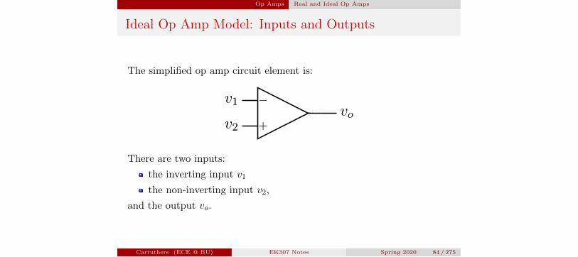
The simplified op amp circuit element is:
�
+v2
v1vo
There are two inputs:
the inverting input v1
the non-inverting input v2,
and the output vo.
Carruthers (ECE @ BU) EK307 Notes Spring 2020 84 / 275
Op Amps Real and Ideal Op Amps
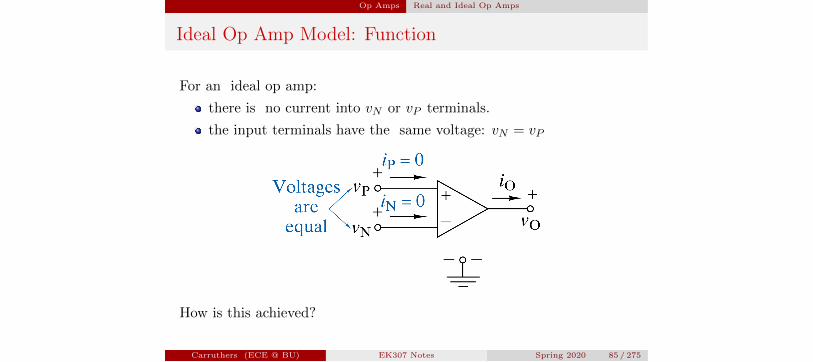
Ideal Op Amp Model: Function
For an ideal op amp:
there is no current into vN or vP terminals.
the input terminals have the same voltage: vN = vP
How is this achieved?
Carruthers (ECE @ BU) EK307 Notes Spring 2020 85 / 275

Op Amps Real and Ideal Op Amps
Ideal Op Amp Model: Rules
For an ideal op amp to function according to the “rules” for the inputs(no current, equal voltage), we need the following conditions:
the power must be on: ±Vcc
a connection (R < 1) between the output and the inverting inputmust be present.
the output must be between the power rails �Vcc and +Vcc
When these conditions are not present, we need to think about theVCVS model for the op amp.
Carruthers (ECE @ BU) EK307 Notes Spring 2020 86 / 275
Op Amps Real and Ideal Op Amps
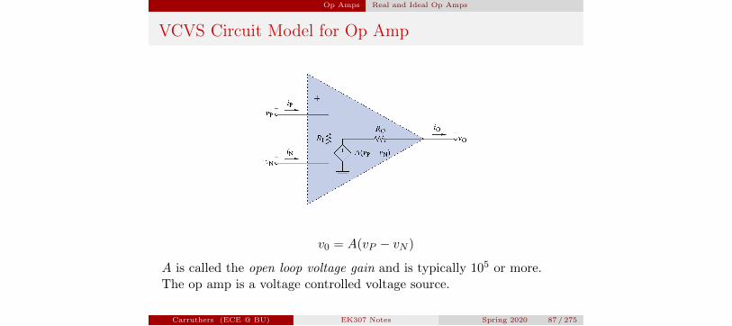
VCVS Circuit Model for Op Amp
v0 = A(vP � vN )
A is called the open loop voltage gain and is typically 105 or more.The op amp is a voltage controlled voltage source.
Carruthers (ECE @ BU) EK307 Notes Spring 2020 87 / 275
Op Amps Real and Ideal Op Amps
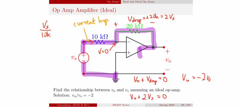
Op Amp Amplifier (Ideal)
�+vs
10 k⌦�
+ +vo
�
20 k⌦
Find the relationship between vo and vs assuming an ideal op-amp.Solution: vo/vs = �2
Carruthers (ECE @ BU) EK307 Notes Spring 2020 88 / 275
Vg currentloop Vdropsefok 2Vs
10k Isgso
VotVdrop O Vos 2b
V 24 0
Op Amps Real and Ideal Op Amps
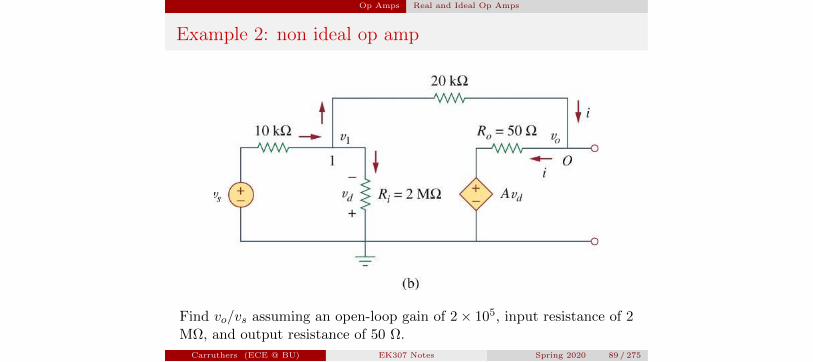
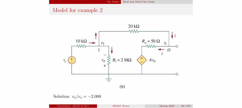
Example 2: non ideal op amp
Find vo/vs assuming an open-loop gain of 2⇥ 105, input resistance of 2M⌦, and output resistance of 50 ⌦.
Carruthers (ECE @ BU) EK307 Notes Spring 2020 89 / 275
Op Amps Real and Ideal Op Amps
Model for example 2
Solution: vo/vs = �2.000
Carruthers (ECE @ BU) EK307 Notes Spring 2020 90 / 275
Op Amps Real and Ideal Op Amps
Feedback: output modifies input
The concept of feedback is critical to many systemsExamples of systems with feedback:
autopilot of aircraft, telescope-pointing, furnace/thermostat,thryroid hormone (all negative feedback);
musical feedback (microphone or guitar pickup is near thespeaker) and oscillators (both positive feedback).
Carruthers (ECE @ BU) EK307 Notes Spring 2020 91 / 275
Op Amps Working with real op amps
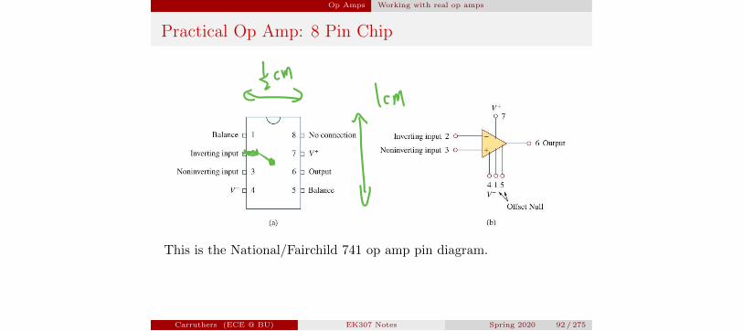
Practical Op Amp: 8 Pin Chip
This is the National/Fairchild 741 op amp pin diagram.
Carruthers (ECE @ BU) EK307 Notes Spring 2020 92 / 275
cma 1cm
I
Op Amps Working with real op amps
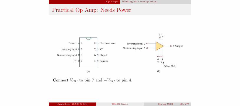
Practical Op Amp: Needs Power
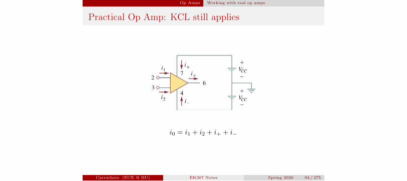
Connect VCC to pin 7 and �VCC to pin 4.
Carruthers (ECE @ BU) EK307 Notes Spring 2020 93 / 275
Op Amps Working with real op amps
Practical Op Amp: KCL still applies
i0 = i1 + i2 + i+ + i�
Carruthers (ECE @ BU) EK307 Notes Spring 2020 94 / 275
Op Amps Working with real op amps
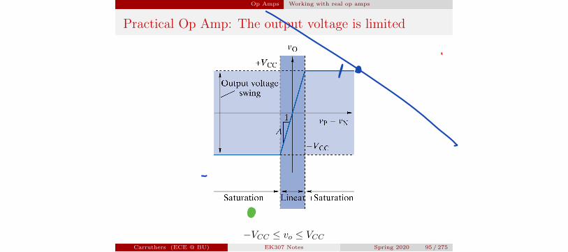
Practical Op Amp: The output voltage is limited
�VCC vo VCCCarruthers (ECE @ BU) EK307 Notes Spring 2020 95 / 275
P
Op Amps Amplifiers
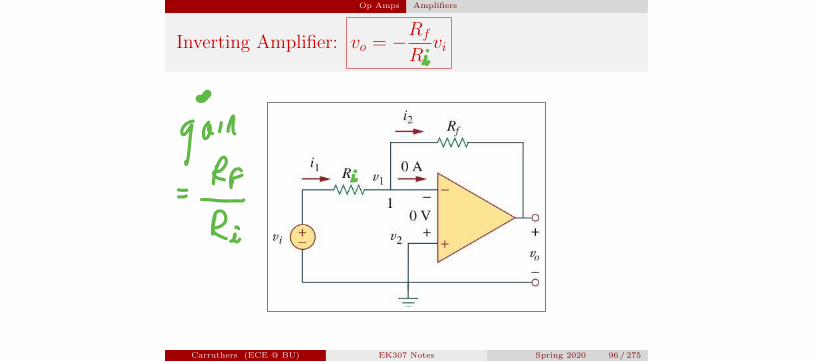
Inverting Amplifier: vo = �Rf
R1vi
Carruthers (ECE @ BU) EK307 Notes Spring 2020 96 / 275
i
gamRI i
Ri
Op Amps Amplifiers
Inverting Amplifier Features
Rf is the feedback resistor
input and feedback connect to inverting input
noninverting input is grounded
the ampifier inverts the sign of the input voltage and providesgain Rf/R1
the input/output relationship does not depend on the op ampparameters (as long as Ri, A, and Ro are su�ciently ideal)
Carruthers (ECE @ BU) EK307 Notes Spring 2020 97 / 275
i
Op Amps Amplifiers
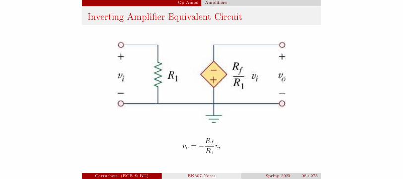
Inverting Amplifier Equivalent Circuit
vo = �Rf
R1vi
Carruthers (ECE @ BU) EK307 Notes Spring 2020 98 / 275
Op Amps Amplifiers
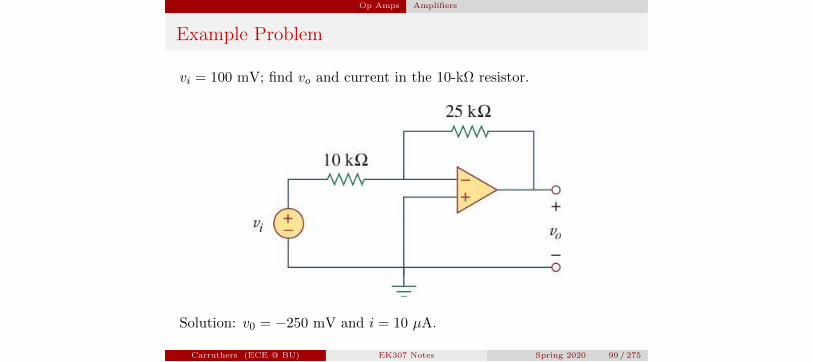
Example Problem
vi = 100 mV; find vo and current in the 10-k⌦ resistor.
Solution: v0 = �250 mV and i = 10 µA.
Carruthers (ECE @ BU) EK307 Notes Spring 2020 99 / 275
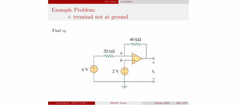
Op Amps Amplifiers
Example Problem:+ terminal not at ground
Find v0
Carruthers (ECE @ BU) EK307 Notes Spring 2020 100 / 275

Op Amps Amplifiers
Transimpedance Amp:convert current-to-voltage
Show thatvo
is= �R.
Carruthers (ECE @ BU) EK307 Notes Spring 2020 101 / 275
Op Amps Amplifiers
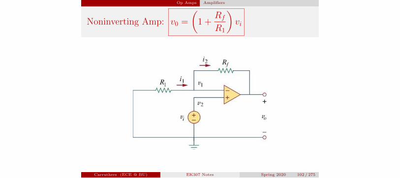
Noninverting Amp: v0 =
✓1 +
Rf
R1
◆vi
Carruthers (ECE @ BU) EK307 Notes Spring 2020 102 / 275
Op Amps Amplifiers
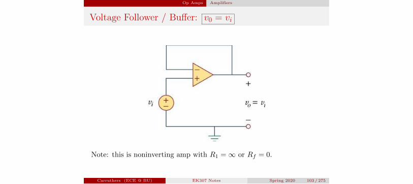
Voltage Follower / Bu↵er: v0 = vi
Note: this is noninverting amp with R1 = 1 or Rf = 0.
Carruthers (ECE @ BU) EK307 Notes Spring 2020 103 / 275
Op Amps Amplifiers
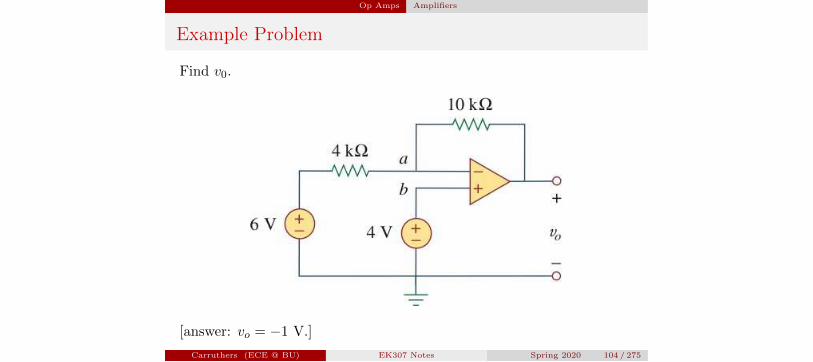
Example Problem
Find v0.
[answer: vo = �1 V.]
Carruthers (ECE @ BU) EK307 Notes Spring 2020 104 / 275
Op Amps Amplifiers
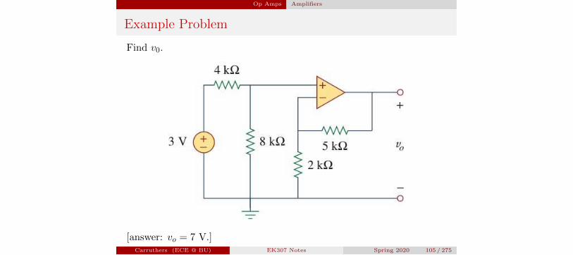
Example Problem
Find v0.
[answer: vo = 7 V.]Carruthers (ECE @ BU) EK307 Notes Spring 2020 105 / 275
Op Amps Applications
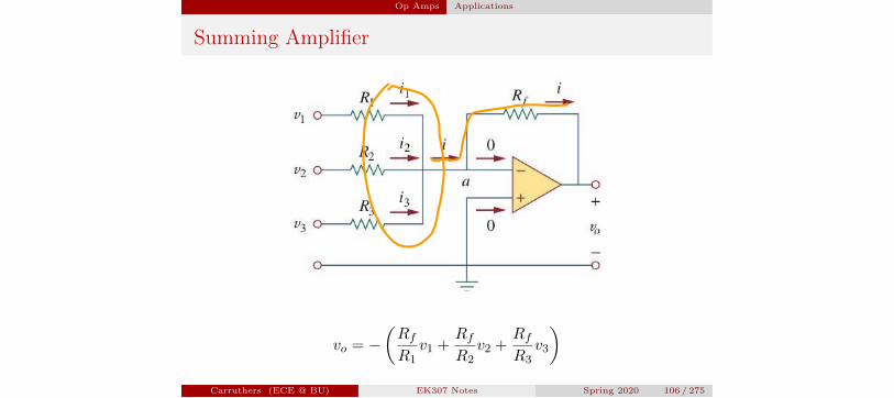
Summing Amplifier
vo = �✓Rf
R1v1 +
Rf
R2v2 +
Rf
R3v3
◆
Carruthers (ECE @ BU) EK307 Notes Spring 2020 106 / 275
Or
Op Amps Applications
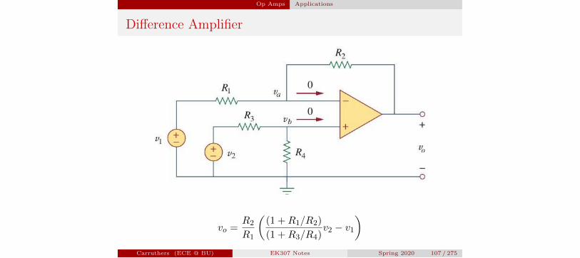
Di↵erence Amplifier
vo =R2
R1
✓(1 +R1/R2)
(1 +R3/R4)v2 � v1
◆
Carruthers (ECE @ BU) EK307 Notes Spring 2020 107 / 275
Op Amps Applications
Di↵erence Amplifier
When R1/R2 = R3/R4, then the circuit is a di↵erence amplifier and
vo =R2
R1(v2 � v1)
and when also R2 = R1 then the circuit is a subtractor and
vo = v2 � v1
Carruthers (ECE @ BU) EK307 Notes Spring 2020 108 / 275
Op Amps Applications
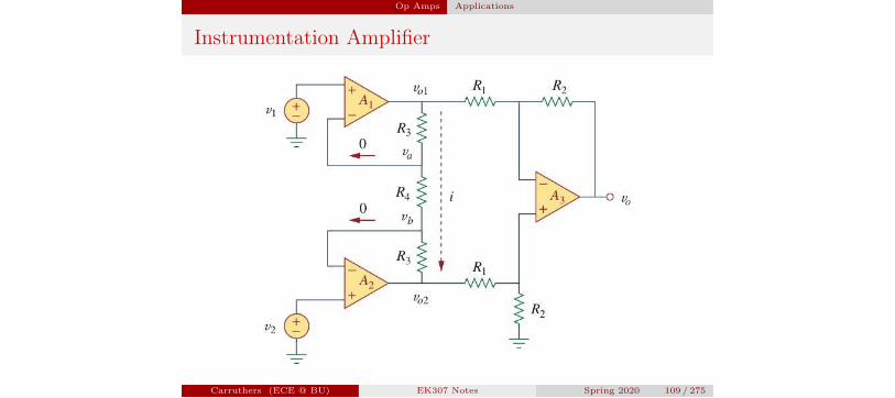
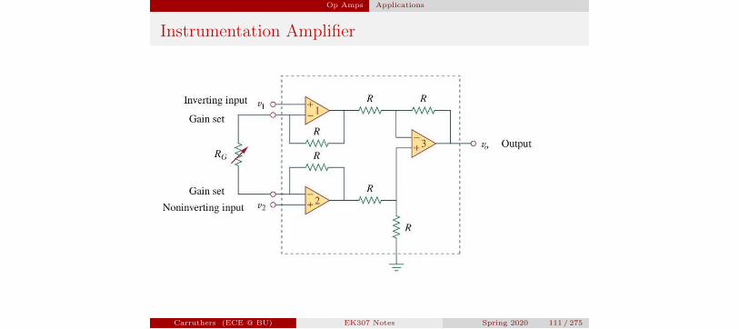
Instrumentation Amplifier
Carruthers (ECE @ BU) EK307 Notes Spring 2020 109 / 275
Op Amps Applications
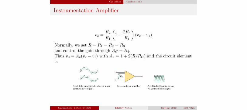
Instrumentation Amplifier
vo =R2
R1
✓1 +
2R3
R4
◆(v2 � v1)
Normally, we set R = R1 = R2 = R3
and control the gain through RG = R4.Thus v0 = Av(v2 � v1) with Av = 1 + 2(R/RG) and the circuit elementis
Carruthers (ECE @ BU) EK307 Notes Spring 2020 110 / 275
Op Amps Applications
Instrumentation Amplifier
Carruthers (ECE @ BU) EK307 Notes Spring 2020 111 / 275

Op Amps Stages and Cascading
Cascaded Op Amp Circuits
A cascade connection:
Output of one stage is input to the next.Stages do not a↵ect each others input/output relationship.
Carruthers (ECE @ BU) EK307 Notes Spring 2020 112 / 275
Op Amps Stages and Cascading
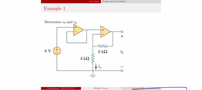
Example 1
Determine v0 and i0.
Carruthers (ECE @ BU) EK307 Notes Spring 2020 113 / 275
o
Op Amps Stages and Cascading
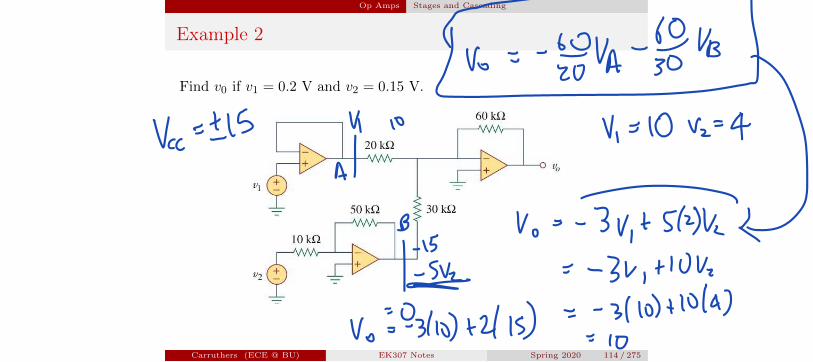
Example 2
Find v0 if v1 = 0.2 V and v2 = 0.15 V.
Carruthers (ECE @ BU) EK307 Notes Spring 2020 114 / 275
v i y
Bis Vos 3kt 514kt1 2 341 104
Vo 031011 2 153 101110 4
10
Op Amps Stages and Cascading
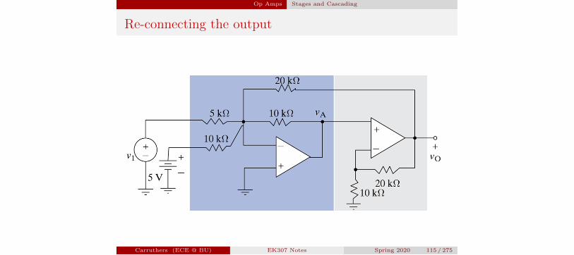
Re-connecting the output
Carruthers (ECE @ BU) EK307 Notes Spring 2020 115 / 275
Op Amps Stages and Cascading
Carruthers (ECE @ BU) EK307 Notes Spring 2020 116 / 275
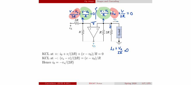
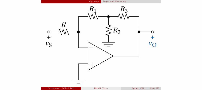
Op Amps Stages and Cascading
KCL at +: i0 + v/(2R) + (v � v0)/R = 0KCL at �: (vs � v)/(2R) = (v � v0)/RHence i0 = �vs/(2R)
Carruthers (ECE @ BU) EK307 Notes Spring 2020 117 / 275
vzfstvrI.io VpYtdotV OZRr rT b
d tVsfr
Op Amps Stages and Cascading
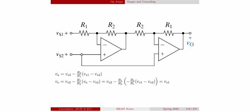
va = vs2 � R2
R1(vs1 � vs2)
vo = vs2 � R1
R2(va � vs2) = vs2 � R1
R2
⇣�R2
R1(vs1 � vs2)
⌘= vs1
Carruthers (ECE @ BU) EK307 Notes Spring 2020 118 / 275