Embed Size (px)
Citation preview
Dr. Tariq Hussein Irrigation and Drainage Engineering
3rd Year
1
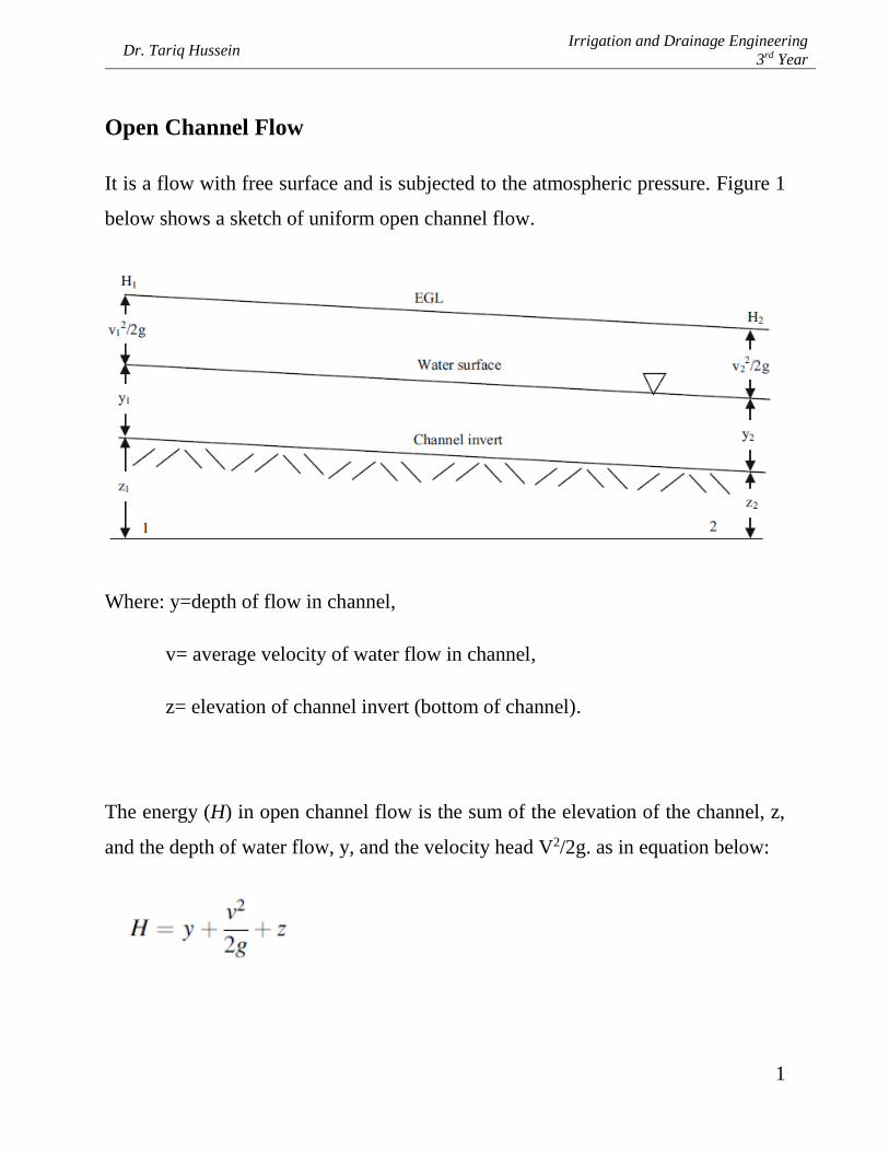
Open Channel Flow
It is a flow with free surface and is subjected to the atmospheric pressure. Figure 1
below shows a sketch of uniform open channel flow.
Where: y=depth of flow in channel,
v= average velocity of water flow in channel,
z= elevation of channel invert (bottom of channel).
The energy (H) in open channel flow is the sum of the elevation of the channel, z,
and the depth of water flow, y, and the velocity head V2/2g. as in equation below:

Dr. Tariq Hussein Irrigation and Drainage Engineering
3rd Year
2
Open channel flow is driven by inertial forces (momentum) and gravitational forces
(differences in elevation of the water surface).
Types of flow in Open Channels
Open channels could be classified in various ways, based on flow change with time
and space.
• Steady flow: A constant in time flow
Uniform flow: A constant in space flow
Nonuniform flow
• Unsteady flow
Unsteady uniform flow (Rare)
Unsteady nonuniform flow
For steady uniform flow in a channel, the water surface slope is the same as the
channel slope (Fig. 1) and momentum is constant in time and space. Thus, the slope
of the energy grade line (EGL) is equal to the slope of the channel.
The flow velocity of a steady uniform flow is determined by Manning’s equation,
which is a function of the channel roughness, energy grade line (equal to slope, S),
and channel dimension (hydraulic radius).
Where: So = channel slope, positive downward in direction of flow, m/m
Dr. Tariq Hussein Irrigation and Drainage Engineering
3rd Year
3
n = Manning’s roughness coefficient,
v = velocity of flow in the channel, m/sec,
Q = flow in channel, m3/sec,
A = cross-sectional area of channel.
The hydraulic radius, R, is representative of the length dimension of the channel
perpendicular to the direction of flow. It is calculated as the cross-sectional area of
the channel divided by the wetted perimeter.
The slope is the difference in elevation between two points (Fig. 1) divided by the
distance between the points.
For uniform flow, the difference in elevation is also equal to the friction loss, Hf.
z1 = Elevation energy at upper end of channel, m
z2 = Elevation energy at lower end of channel, m
L = Length of channel, m
θ = channel slope, degrees.
By substituting into equations above, we get:

Dr. Tariq Hussein Irrigation and Drainage Engineering
3rd Year
4
State of flow
The state or behaviour of open channel flow is governed basically by the effect of
viscosity and gravity relative to the inertial forces of the flow.
• Effect of viscosity. This effect is relative to the inertial forces, which can
cause the flow to be laminar, turbulent, or transitional.
The flow becomes laminar when the viscous force is so strong with respect to the
inertial force. In this type of flow, the water particles seem to move in definite
smooth paths, and infinitesimally thin layers of fluid seem to slide over each other.
The flow is turbulent is the viscous force is so weak with respect to the inertial force.
In this flow, the water particles move in irregular path.
Between the laminar and turbulent states, there is a mixed, or transitional state.
The effect of viscosity relative to the inertial forces can be represented by Reynold
number 𝑅𝑒 = 𝑉.𝐿
ʋ
Where V is the velocity of flow in L/T,
L is a characteristic length in Liters, which is equal to the hydraulic radius R in the
case of open channels. Therefore,
𝑅𝑒 = 𝑉. 𝑅
ʋ

Dr. Tariq Hussein Irrigation and Drainage Engineering
3rd Year
5
ʋ (nu), is the kinematic viscosity of water in L2/T.
• Effect of gravity. The effect of gravity on the state of the flow is
represented by Froude number, defined as Fr = 𝑉
√𝑔.𝐷
Where, D is the hydraulic depth.
When Fr =1, the flow is said to be critical,
Fr > 1, the flow is supercritical,
Fr < 1, the flow is subcritical.
Types of open channel
Open channels are classified according to their origin, which may be natural or
artificial.
• Natural channels. They include all the watercourses that exist naturally
on earth. They could be varying in sizes from tiny hillside rivulets,
through brooks, streams, small and large rivers.
Underground water with free surface is also considered an open channel.
The hydraulic properties of natural channels are usually irregular.
• Artificial channels. Those are constructed or developed by human
intrusion. They include navigation channels, irrigation canals and flumes,
drainage ditches, spillways, etc. They are usually designed with sections
of regular shapes. In engineering practice, artificial channels are given
different names, such as:
Canals: They are usually long, mild sloped channels built in the ground, which
maybe unlined or lined.

Dr. Tariq Hussein Irrigation and Drainage Engineering
3rd Year
6
Flumes: They could be channels of wood, concrete or masonry. They are usually
supported on or above the ground surface to carry water across a depression.
Culverts: They are covered channels of relatively short lengths built to drain water
through highways and railroads.

Dr. Tariq Hussein Irrigation and Drainage Engineering
3rd Year
7
Classification of Canals
Canals are generally trapezoidal in shape constructed on the ground to carry water
to the fields either from the river or from a tank or reservoir.
They are generally classified in the following ways:
a) Classification based on the source of supply
1- Permanent canals, when they are fed by a permanent source of supply.
2- Inundation canals, they draw their supply from rivers when there is a
high stage of water.
b) Classification based on the function of the canal
1- Irrigation canals, carry water to the agricultural fields.
2- Carrier canals, besides doing irrigation, they carry water for other canals.
3- Feeder canals, constructed with idea of feeding two or more canals.
4- Navigation canals.
5- Power canal.
c) Classification based on the boundary surface of the canal
1- Alluvial canals, excavated in alluvial soils, such as silt.
2- Non-alluvial canals, excavated in non-alluvial soils, such as loam, clay, rock.
3- Rigid boundary canals, they have rigid sides and rigid base, such as lined
canals.
d) Classification based on relative importance in a given network of canals
1- Main canal, carries water directly from the river of reservoir and they cannot
be used for direct irrigation due to their heavy supplies.

Dr. Tariq Hussein Irrigation and Drainage Engineering
3rd Year
8
2- Branch canals, they are branches of main canals which feed major and minor
distributaries, they cannot provide direct irrigation unless exceptional
circumstances when direct outlets may be provided.
3- Major distributary, they take off branch or main canals but their discharge is
usually less than that of branch canals.
4- Minor distributary, they take off branch canals or major distributaries. They
supply water to the water courses through outlets.
5- Water course, they are sometimes called field channels, small canals which
ultimately supply water to the field.
Geometric elements of channels

Dr. Tariq Hussein Irrigation and Drainage Engineering
3rd Year
9
Definitions:
The water area, A: is the cross section of the flow normal to the direction of the flow.
Wetted perimeter, P: is the length of the line of intersection of the channel wetted
surface with the cross section plan normal to the direction of flow.
Hydraulic radius, R: is the ratio of the water area to its wetted perimeter, 𝑅 = 𝐴
𝑃.
Top width, T: is the width of the channel section at the free surface.
Hydraulic depth, D: is the ratio of the water area to the top width 𝐷 = 𝐴
𝑇.

Dr. Tariq Hussein Irrigation and Drainage Engineering
3rd Year
10
Canal cross section elements
F.S.L: Full supply level,
b: Canal bed,
1:Z : Side slope,
Bern or Berm: A narrow strip of land, made on both sides of a channel at G.L. Its
width depends on the size of the channel.
Why berms are used?
1- They prevent the earthwork from falling inside the canal.
2- They provide a scope for future widening of the canal.
Free board (F): It is the vertical distance between F.S.L and top of the lowest bank
of the channel.
Free board (f1): The distance between the water level and canal surface for the
protection of over-topping.
Free board (f2): The distance between the berm level and bank level for the
protection of flooding.
𝐹 = 𝑓1 + 𝑓2, 𝑓1 = 0.2 + 0.1 𝑑, 𝑓1 + 𝑓2 = 1
3 𝑑,

Dr. Tariq Hussein Irrigation and Drainage Engineering
3rd Year
11
f2 = 1
3 * d – 𝑓1, should not be less than 0.2m.
Design of open channels
1- Non-alluvial channels
One of the most important equations for channel’s design is Manning’s formula:
, which is used in two methods:
• Method of permissible velocity
Procedure:
Step1: Given Q, n, So, Z, V
Step2: Based on 𝑄 = 𝑉. 𝐴, compute A.
Step3: Compute R from Manning’s equation.
Step4: Find 𝑃 =𝐴
𝑅.
Step5: From A and P, find b and d simultaneously by geometry.
Step6: Add free board.
Ex: Design an irrigation channel to carry a discharge of 15 cumecs (m3/sec) with a
permissible velocity of 0.75m/sec, assume bed slope of 1/3600, Manning’s
coefficient of 0.03 and a side slope of 1:1.

Dr. Tariq Hussein Irrigation and Drainage Engineering
3rd Year
12
Ans./ 𝐴 =𝑄
𝑉 =
15
0.75 = 20 m2 Since A=b.d+z.d2,
then 20= b.d+d2 ………………….. (1)
From Manning’s eq. 𝑉 =𝑅2/3𝑆𝑜0.5
𝑛 0.75 =
𝑅2/3 (1/3600)0.5
0.03
R = 1.568m
P=𝐴
𝑅 =
20
1.568 = 12.755m
Since P = b+2d √1 + 𝑧2 12.755 = b+ 2d √1 + 12
b = 12.755 – 2.828 d ……….. (2) ؞
Substituting in eq. (1) 20 = (12.755-2.828 d) + d2
.d = 4.6m or d = 2.38m ؞
If d = 4.6m then b = -0.254m (Neglected)
Or d = 2.38, then b = 6m.
The free board: f1= 0.2 + 0.1 d = 0.2 + 0.1 * 2.38 = 0.438 m
f1+f2= 1
3 d f2 =
1
3 * 2.38 – 0.438 = 0.355m.
• Method of (b/d) ratio
Procedure:
Step1: Given Q, n, So, and Z

Dr. Tariq Hussein Irrigation and Drainage Engineering
3rd Year
13
Step2: Assume b/d as follows:
-Q < 1 m3/sec 𝑏
𝑑 = 2 tan
𝛳
2
- Q = (1-10) m3/sec 𝑏
𝑑 = (1-3)
- Q > 10 m3/sec 𝑏
𝑑 = (3-10)
Step3: Use Manning’s eq. 𝑄 =𝐴 𝑅2/3𝑆𝑜0.5
𝑛
Step4: b is rounded, return to Manning’s eq. to find d.
Step5: Check minimum permissible velocity, and Fr.
-Vmin = 0.46 m/sec For lined channels
- Vmin = 0.76 m/sec For unlined channels
And Fr = 𝑉
√𝑔𝐷 must be ≤ 0.6
If Fr = 1, then critical flow,
Fr < 1, subcritical flow,
Fr > 1, supercritical flow
𝐷 = 𝐴
𝑇

Dr. Tariq Hussein Irrigation and Drainage Engineering
3rd Year
14
Step6: Adding the free board.
Ex: Given the following information about a lined irrigation canal, water level at
k0.0 = 32.3m, required water level at k4.8 = 27.5m, max. allowable slope =
75cm/km, min. allowable slope = 15cm/km, side slope 1.5:1, design discharge =
28m3/sec, and n = 0.015. Design the following:
a- The proper longitudinal slope for the canal.
b- The canal cross-section if 𝑏
𝑑 = 3.
Ans./
a- So = 32.3−27.5
4.8 = 1m/km but max. allowable is 75cm/km!! Not ok!
Then use So= 75cm/km.
b- 𝑄 =𝐴 𝑅2/3𝑆𝑜0.5
𝑛
𝑄.𝑛
𝑆𝑜0.5 = (
𝑏
𝑑+ 𝑍) 𝑑2 ∗ [
(𝑏
𝑑+𝑧)𝑑2
(𝑏
𝑑+2√1+𝑍2)∗𝑑
]
2/3
28∗0.015
(75
105)0.5 = (3 + 1.5)𝑑2 ∗ [
(3+1.5)𝑑2
(3+2√1+1.52)∗𝑑]
2/3
15.336 = 4.5𝑑2 ∗ [4.5𝑑2
(3+2√1+1.52)∗𝑑]
2/3
d = 1.74m,
and b = 3*1.74 = 5.23m ≈ 5.25m
Substitute value of b= 5.25m in Manning’s eq. to find d.
𝑄 =𝐴 𝑅2/3𝑆𝑜0.5
𝑛 15.336 = (5.25𝑑 + 1.5𝑑2) ∗ [
(5.25𝑑+1.5𝑑2)
(5.25+2𝑑√1+1.52)]
2/3
d = 1.739m ≈ 1.74m.

Dr. Tariq Hussein Irrigation and Drainage Engineering
3rd Year
15
𝑉 =𝑄
𝐴 =
28
5.25∗1.74+1.5∗(1.74)2 = 2.05 > 0.46 Ok.
Fr = 𝑉
√𝑔𝐷, and 𝐷 =
𝐴
𝑇,
Fr = 2.05
√9.81∗(5.25∗1.74+1.5∗1.722
5.25+2∗1.5∗1.74)
= 0.5 < 0.6 Ok.
Add free board:
f1= 0.2 + 0.1 d = 0.2 + 0.1 * 1.74 = 0.37m ≈ 0.4m
f1+f2= 1
3 d f2 =
1
3 * 1.74 – 0.4 = 0.18 < 0.2m, then use f2=0.2m
H.W: Given Q=12.5m3/sec, Z=1, n=0.0225 and So=30cm/km. Design the canal
cross-section and check the design if the min permissible velocity =0.76m/sec.
Ans. (d=2.69, V=0.94m/sec, Fr=0.227)

Dr. Tariq Hussein Irrigation and Drainage Engineering
3rd Year
16
QB: What are the types of open channels? And explain the effect of viscosity on the
flow.
QA: A- Classify canals according to their importance in the network.
B- Define culverts.

Dr. Tariq Hussein Irrigation and Drainage Engineering
3rd Year
17
2- Design of alluvial canals
It is a process of controlling the flow velocity in such as away that the silt flowing
in the channel is not dropped in the bed without scouring the channel.
Some of theories towards the design of non-silting non-scouring channel section are
presented:
1) Lacey’s Theory
The fundamental requirements stated by Lacey for a channel are as follows:
• The channel flows uniformly in incoherent alluvium. Incoherent alluvium
is the loose granular material which can scour or deposit with the same
ease.
• The characteristics and the discharge of the sediment are constant.
• The water discharge in the channel is constant.
The channel design procedure is as follows:
Step 1: Calculate the silt factor 𝑓 = 1.76 √𝑚𝑑
Where f = silt factor
𝑚𝑑 = diameter of silt in mm, or it’s called mean particle size.
Step 2: Find the velocity 𝑉 = (𝑄 𝑓2
140)
1/6
Step 3: Determine the area A=Q/V
Step 4: Compute 𝑃 = 4.75 √𝑄, and 𝑅 = 0.48 (𝑄
𝑓1)1/3 and 𝑆𝑜 = 0.0003 (
𝑓15/3
𝑄1/6 )

Dr. Tariq Hussein Irrigation and Drainage Engineering
3rd Year
18
Ex: Design a stable channel for carrying a discharge of 30m3/s using Lacey’s method
assuming silt factor equal to 1.0.
Ans.
𝑃 = 4.75 √𝑄 = 4.75 √30 = 26.02m
𝑅 = 0.48 (𝑄
𝑓1)1/3= 0.48 (
30
1)1/3= 1.49m
𝑆𝑜 = 3 𝑥 10−4 (𝑓1
5/3
𝑄1/6 ) = 3 𝑥 10−4 (15/3
301/6) = 1.702 × 10⁻⁴
*Assume final side slope of the channel as 0.5H:1V (generally observed field value)
P = b+2d √1 + 𝑧2 26.02= b+2d√1 + 0.52
b = 26.02 – 2.24d……………………….. (1)
and A= bd+z.d2 = P.R 26.02 × 1.49 = bd+0.5d2
38.77 = 26.02d – 2.24d2 + 0.5d2 1.74d2 – 26.02d + 38.77 = 0
Either d= 13.28m, then b would be a negative value!! Neglected.
Or d=1.68m, then b= 26.02 – 2.24 × 1.68 = 22.23m
Then add free board
H.W: Design an irrigation channel for a discharge of 50m3/s adopting the available
ground slope of 1.5 × 10⁻⁴. Then find the size of suitable river bed material.
(Ans. d= 1.99m, b= 29.13m, md=0.3mm), then compute the free board.

Dr. Tariq Hussein Irrigation and Drainage Engineering
3rd Year
19
2) Kennedy’s Theory
The procedure of this theory is
Step 1: Assume (d) by trial and error, where d is the depth of water in (m).
Step 2: Calculate the critical velocity* in (m/sec) by using eq. 𝑉𝑜 = 0.55 𝑑0.64
Which is defined as the mean velocity that will not allow scouring or silting in a
channel having depth of flow equal to (d)m.
Step 3: Find the area of the section 𝐴 = 𝑄
𝑉𝑜
Step 4: Since 𝐴 = 𝑏𝑑 + 𝑧. 𝑑2 , then find b.
Step 5: Find P and R.
Step 6: Find (V) from Manning’s equation, which must equal to (Vo). If not, then
assume another (d).
*This critical velocity should be distinguished from the critical velocity of flow in
open channels corresponding to Froude number equal to 1.
Ex: Design a channel carrying a discharge of 30m3/s with critical velocity ratio and
Manning’s n equal to 1.0 and 0.0225, respectively. Assume that the bed slope is
equal to 1 in 5000.
Ans. Assume d=2m
𝑉𝑜 = 0.55𝑚 𝑑0.64 = 0.55 (2)0.64 = 0.857 m/sec
A=Q/Vo = 30/0.857 = 35.01m2

Dr. Tariq Hussein Irrigation and Drainage Engineering
3rd Year
20
For a trapezoidal channel with side slope 1H : 2V, or 0.5H:1V
A=bd+z.d2 35.01=2b+0.5(4) b= 16.51m
𝑅 =𝐴
𝑃 =
35.01
16.51+2∗2(√1+0.52) = 1.67m
Therefore, from Manning’s eq.
𝑉 =1
𝑛 𝑆𝑜
1/2 𝑅2/3 =
1
0.0225 (
1
5000)1/2 1.672/3 = 0.885 𝑚/𝑠𝑒𝑐
Since the velocities obtained from Kennedy’s equation and Manning’s equation are
appreciably different, assume d = 2.25m and repeat the above steps.
𝑉𝑜 = 0.55 2.250.64 = 0.924 m/sec
A= 30/0.924 = 32.47 m2
b(2.25) + (0.5) (2.25)2 = 32.47 b= 13.31 m
R=1.77m
𝑉 =1
𝑛 𝑆𝑜
1/2 𝑅2/3 = 0.92 m/s
Since the two values of the velocities are matching, the depth of flow can be taken
as equal to (d = 2.25m) and the width of trapezoidal channel (b = 13.31m).
Then add the fee board. f1

Dr. Tariq Hussein Irrigation and Drainage Engineering
3rd Year
21
*Report.
Deadline: 11/4/2019
About Open channels. Problems, issues, Maintenance and management.
Min. 8 pages, max 12 pages.

Dr. Tariq Hussein Irrigation and Drainage Engineering
3rd Year
22
To reduce the number of trials in finding (d), you can use the table below to use
recommended b/d values for assumption.
H.W: A stable channel is to be designed for a discharge of 40m3/s. Calculate the
dimensions of the channel using Kennedy’s method. Use a Manning’s coefficient of
0.0225 and bed slope of 1/5000.
Ex: A circular concrete culvert of diameter 100cm carries water of depth 40cm to
irrigate a 20 hectares field. What could be the discharge of this canal if the slope was
0.002? Use Manning’s n of 0.014.
Ans.
Length BC = √(0.5)2 − (0.1)2 = 0.49m
Area BoA = 2∗0.49∗0.1
2 = 0.049m2
Angle CoB = cos−1 0.1
0.5 = 78.46o
Angle AoB = 2* 78.46 = 156.92o ؞
b/d

Dr. Tariq Hussein Irrigation and Drainage Engineering
3rd Year
23
180𝑜
ℎ𝑎𝑙𝑓 𝑐𝑖𝑟𝑐𝑙𝑒 𝑎𝑟𝑒𝑎 =
156.92𝑜
𝑐𝑖𝑟𝑐𝑙𝑒 𝑠𝑒𝑐𝑡𝑖𝑜𝑛 𝑎𝑟𝑒𝑎 circle section area = 0.342m2 ؞ ,
water area = 0.342 – 0.049 = 0.293m2 ؞
360𝑜
𝑐𝑖𝑟𝑐𝑙𝑒 𝑝𝑒𝑟𝑖𝑚𝑒𝑡𝑒𝑟 =
156.92𝑜
𝑤𝑒𝑡𝑡𝑒𝑑 𝑝𝑒𝑟𝑖𝑚𝑒𝑡𝑒𝑟 wetted perimeter (P) = 1.37m ؞
𝑄 ؞ = 1
𝑛 𝑅2/3 𝑆𝑜1/2 𝐴 =
1
0.014 (
0.293
1.37)
2
3 (0.002)1
2 (0.293)
𝑄 ؞ = 0.335 m3/sec.
H.W: Design the best cross-section of a trapezoidal canal to irrigate a field of 1000
hectare, where the water supply is 100 (m3/hectare/day). Knowing that the side
slope is 1:1 and bed slope of 10 cm/km. Use n = 0.02.
Ans. (d=1.133m, b=1.602m)
Hint: Q = water duty * area = (100 * 1000) / (24*3600) = 1.157 m3/s
Find the relationship bet. b & d. then solve..

Dr. Tariq Hussein Irrigation and Drainage Engineering
3rd Year
24
H.W: The slope of a channel in alluvium is 1/5000; Lacey’s silt factor is 0.9. Find
the channel section and maximum discharge which can be allowed to flow in it.
(Ans: b=7.45m, d=0.88m, Q=3.924m3/sec)
Quiz: Check the adequacy of an irrigation channel of dimensions (b=9.69m,
d=1.7m), which is designed to supply 85 (m3/hectare/day) to a 10000 hectares field.
Use Kennedy’s theory with n = 0.0225, So=1/5000.
Sol. Required Q = (85 * 10000)/(24*3600) = 9.84 m3/sec
Vo = 0.55 d0.64 = 0.773 m/sec
A = bd+ zd2 = 17.91 m2
Available Q = A V = 17.91 * 0.773 = 13.85 m3/sec > 9.84 m3/sec
.The canal is adequate ؞
Comparisons between Lacey’s and Kennedy’s theories
1- Kennedy introduced the Critical Velocity Ratio (m) but he did not give any idea of how
to measure m. While Lacey introduced the silt factor (f) and suggested a method to
determine(f) by relating it with particle size.
2- Kennedy assumed that silt is kept in suspension because of eddies generated from the bed
only and so he proposed a relation between V and d. Lacey assumed that silt is kept in
suspension because of eddies generated from the entire perimeter and so he proposed a
relation between V and R.
3- Kennedy gave no formula of determination of longitudinal slope of the canal, where the
slope is to be given based on experience. Lacey gave a formula for the longitudinal slope
of the canal.

Dr. Tariq Hussein Irrigation and Drainage Engineering
3rd Year
25
4- Lacey’s theory does not involve any trial and error in the design procedure whereas
Kennedy’s theory involves a trial and error procedure.
5- The basic concept of both theories is the same that the silt remains in suspension due to
the force of vertical eddies.
Losses in Canals
When water continuously flows in a canal, losses take place due to seepage, deep
percolation and evaporation. These losses should be properly accounted for,
otherwise lesser quantity of water will be available for cultivation at the tail end.
These losses are sometimes called transmission loss.
Water losses in canals can be classified into three categories:
i) Evaporation losses.
This loss is generally a small percentage of the total loss in unlined canals (1 to
2 percent of the total water entering the canal).
The evaporation losses depend on the following:
• Climate factors, such as temperature, humidity and wind velocity.
• Canal factors, such as water surface area, water depth and velocity of
flow.
The evaporation losses are maximum in unlined canals due to the wider water
surface area and shallower water depth.
The average evaporation loss per day at hot summers may vary between 4mm
to 10mm.

Dr. Tariq Hussein Irrigation and Drainage Engineering
3rd Year
26
ii) Transpiration losses.
This loss takes place through lots of vegetation and weeds growing along the
bank of the canal. This loss forms an extremely small part of total losses.
iii) Seepage losses.
These losses form the major loss in an unlined canal. The seepage losses are due
to:
• Absorption of water in the upper layers of soil below the canal bed,
• Percolation of water into water table. Percolation losses are always much
more than absorption losses.
The seepage loss varies with the type of the material through which the canal runs.
Obviously, the loss is greater in coarse sand and gravel, less in loam, and still less in
clay soil.
Rate of water loss
Canal loss maybe expressed in any of the following methods:
1- As cumecs per million sq. meter of wetted perimeter (most recommended)
2- As depth of water lost per day over the wetted perimeter.
3- As percentage of the canal discharge.
4- As percentage per kilometer length of the canal.
In absence of any other data, the canal losses (transmission losses) may be taken as:
2.5 cumecs per million sq. meter of wetted perimeter of unlined canals (2.5
m3/sec/106m2), and
0.60 cumecs per million sq. meter of wetted perimeter of lined canals.

Dr. Tariq Hussein Irrigation and Drainage Engineering
3rd Year
27
The following empirical relation has also been found to give comparable results
q = 1/200 (b + d)2/3
where q is the loss expressed in m3/sec per kilometer length of canal and (b and d)
are, respectively, canal bed width and depth of flow in metres.

Dr. Tariq Hussein Irrigation and Drainage Engineering
3rd Year
28
Canal Outlets
An outlet is a small masonry structure which admits water from a distributary
channel to a watercourse or a field channel. It also acts as a discharge measuring
device. The discharge through an outlet is usually less than 0.085 m3/s.
The main objective of providing an outlet is to provide ample supply of water to the
fields, whenever needed.
Canal outlets should satisfy the following requirements:
i- They must be strong and simple with no moving parts, periodic attention
and maintenance are necessary.
ii- Farmers should not be able to tamper with its functioning, and any
interference should be easily detectable.
iii- The cost of outlets should be cheap, because there is a large number of
them will be installed in an irrigation network.
iv- The outlet should draw its fair share of silt carried by the distributary
channel.
v- The outlets should be able to function efficiently even at low heads.
vi- The design should be simple that they can be constructed or fabricated by
local masons or technicians.
Types of outlets
Canal outlets are of the following three types:
(i) Non-modular outlets: The discharge capacity in these outlets depends on the
difference of water levels in the distributary and the watercourse. Example of these
are submerged pipe outlets, masonry sluices and orifices which are fixed in the
canal bank at right angles to the direction of flow in the distributary. As shown in
the submerged pipe outlet in figure below.

Dr. Tariq Hussein Irrigation and Drainage Engineering
3rd Year
29
(ii) Semi-modular, or flexible module outlets: The discharge in this type depends
only on the water level in the distributary and is unaffected by the water level in the
watercourse. The exit end of the pipe is placed higher than the water level in the
watercourse. Examples of this type are pipe outlets, open flume outlets.
(iii) Modular outlets: Here the discharge is independent of the water levels in the
distributary and watercourse. A modular outlet supplies fixed discharge. In case of
excess or deficient supplies in the distributary, the tail-end reach of the distributary
may either get flooded or be deprived of water. The most common outlets of this
type are Gibb’s rigid modules.
If H is the difference in water levels of the distributary and the watercourse then the
discharge Q through the outlet can be obtained from the equation:
𝑄 = 𝐴. 𝑉 = (𝜋
4𝑑2) √2𝑔𝐻 (
𝑑
1.5+𝑓𝐿)
1/2 = CA √2𝑔𝐻
Where 𝐻 =𝑉2
2𝑔[1.5𝑑 + 𝑓
𝐿
𝑑] 𝑉 = √2𝑔𝐻 (
𝑑
1.5𝑑+𝑓𝐿)
1/2
And 𝐶 = (𝑑
1.5𝒅+𝑓𝐿)
1/2 (which is called the coefficient of discharge)
d= diameter of pipe outlet, L= length of pipe outlet, f= friction factor of pipe.

Dr. Tariq Hussein Irrigation and Drainage Engineering
3rd Year
30
Parameters for Studying the Behaviour of Outlets
To understand the criteria of judging the behaviour and function of outlets, the
following definitions are useful:
-Flexibility: The ratio of the rate of change of discharge of an outlet to the rate of
change of discharge of the distributary channel, which is designated as F.
𝐹 = 𝑑𝑞/𝑞
𝑑𝑄/𝑄,
where F = flexibility, q = discharge through the outlet, Q = discharge through the
distributary channel.
Now, for the watercourse:
q = kHm
where k=constant, m=outlet index, H= head acting on the outlet.
𝑑𝑞
𝑞= 𝑚
𝑑𝐻
𝐻 …………………………………………….. (1)
Similarly, for the distributary channel,
𝑄 = 𝐶𝐷𝑛, where Q = discharge of the distr. channel, C=constant, n= canal index,
D= depth of the distr. channel.
𝑑𝑄
𝑄= 𝑛
𝑑𝐷
𝐷 ……………………………………………… (2)
Dividing (1) and (2), we get:
𝐹 = 𝑑𝑞/𝑞
𝑑𝑄/𝑄 =
𝑚 𝑑𝐻
𝐻
𝑛 𝑑𝐷
𝐷
= 𝑚
𝑛 𝐷
𝐻 𝑑𝐻
𝑑𝐷

Dr. Tariq Hussein Irrigation and Drainage Engineering
3rd Year
31
Since any change in the water depth causes equal change in the head causing flow,
we have dH=dD. Then the flexibility expression becomes:
𝑭 = 𝒎
𝒏
𝑫
𝑯
Depending upon the value of F, the outlets can be classified as:
(i) proportional outlets (F = 1), where the rate of change of outlet discharge
equals that of the distributary discharge.
(ii) hyper-proportional outlets (F > 1), and
(iii) sub-proportional outlets (F < 1).
-Sensitivity: It is the ratio of the rate of change of discharge of an outlet to the rate
of change in the water surface level of the distributary channel with respect to the
depth of flow in the channel.
𝑆 = 𝑑𝑞/𝑞
𝑑𝐺/𝐷
Where: S= sensitivity of the outlet, q= discharge through the outlet, G= gauge
reading (G=0 when q=0), D= depth of water in the distr. channel.
dG = dD 𝑆 ؞ = 𝑑𝑞/𝑞
𝑑𝐷/𝐷 …………………… (1)
But 𝐹 = 𝑑𝑞/𝑞
𝑑𝑄/𝑄 where
𝑑𝑄
𝑄= 𝑛
𝑑𝐷
𝐷
𝐹 ؞ = 𝑑𝑞
𝑞 /𝑛
𝑑𝐷
𝐷 ………………………………….. (2)
From (1) and (2), we get:
𝑆 = 𝑛 𝐹

Dr. Tariq Hussein Irrigation and Drainage Engineering
3rd Year
32
It is evident from this equation that the sensitivity of modular outlets is zero.
Ex: A semi-modular pipe outlet of diameter 15cm is to be installed on a distributary
with its bed level and full supply level at 100.3m and 101.5m, respectively. The
maximum water level in the watercourse is at 101.15 m. Set the outlet for maximum
discharge and calculate it. The coefficient C in the discharge equation may be taken
as 0.62. Is the setting proportional, sub-proportional or hyper-proportional? Take
m=1/2, n=5/3.
Ans. D = 101.5 – 100.3 = 1.2m
H = (101.5 – 101.15) − 0.15
2 = 0.275 m
Q = CA √2 𝑔𝐻 = 0.62 * 3.14∗ 0.152
4√2 ∗ 9.81 ∗ 0.275 = 0.0254 m3/sec
Flexibility, 𝐹 = 𝑚
𝑛 𝐷
𝐻 =
1/2
5/3
1.2
0.275 = 1.309 > 1
Therefore, the setting is hyper-proportional.
H.W: A submerged pipe outlet has the following data: F.S.L of distributary=
100.00m, F.S.L of watercourse= 99.90m, length of the pipe= 9m, diameter of
pipe= 20cm, coefficient of friction= 0.005. Find the discharge through the outlet.
(Ans. 0.033 m3/sec)
Ex: Design a submerged pipe outlet for the following data:
Discharge through outlet = 0.04 cumecs,
F.S.L of distr. channel = 100.00m,
F.S.L of watercourse = 99.90m,

Dr. Tariq Hussein Irrigation and Drainage Engineering
3rd Year
33
Full supply depth of distr. channel = 1.1m
Assume the discharge coefficient = 0.7
Ans. Given q = 0.04 cumecs and C = 0.7
Available head (H) = 100 – 99.9 = 0.1m
q = CA √2 𝑔𝐻 0.04 = 0.7 A √2 ∗ 9.81 ∗ 0.1
A = 0.0408 m2 = 3.14∗ 𝑑2
4 d = √
4∗0.0408
3.14 = 0.228m = 22.8cm
Hence use a pipe of 25cm diameter.
A very important H.W: A distributary channel having bed width 5.00m and full
supply depth of 1.20m carries 3.0m3/sec of discharge. A semi-modular pipe outlet in
this channel has a command area requires 0.0165m3/sec. Determine the size of the
outlet and set it for sub-proportionality with a flexibility of 0.9. Assume the length
of the pipe as 3.0m and friction factor as 0.03. The available diameters of the pipe
are 150, 125, 100, and 75 mm.
How does this outlet behave if the distributary runs below FSL at 1.0m depth? Take
m=1/2, n=5/3.
Ans.
F= m/n * D/H
H= 0.4m
Q= (𝜋
4𝑑2) √2𝑔𝐻 (
𝑑
1.5𝑑+𝑓𝐿)
1/2 = (
𝜋
4𝑑2) (
𝑑 (2𝑔𝐻)
1.5𝑑+𝑓𝐿)
1/2 = [(
𝜋
4)2
𝑑5 (2𝑔𝐻)
1.5𝑑+𝑓𝐿]
1/2

Dr. Tariq Hussein Irrigation and Drainage Engineering
3rd Year
34
Q= [4.84 𝑑5
1.5𝑑+0.09]
1/2
Assume d=0.1m, then Q= 0.0142 m3/sec, which is less than required (0.0165m3/sec)
For d= 0.125m, then Q= 0.023 m3/sec, OK!
Therefore, recommended diameter of the outlet is 125 mm.
When the distributary is running at 1.0 m depth (i.e., 0.2m below FSL) then:
H = 0.4 – 0.2 = 0.2m and D = 1.0m.
F = 1/2
3/5 0.1
0.2 = 1.5 > 1.0
Therefore, the outlet behaves as hyper-proportional outlet.

Dr. Tariq Hussein Irrigation and Drainage Engineering
3rd Year
35
Maintenance of irrigation channels
After completing the construction of an irrigation system, it becomes essential to
maintain it for its proper and efficient functioning.
Proper maintenance of an irrigation system is necessary because of the following:
(i) The delivery system of the irrigation project should be in a good condition for
effective water management and to retain system’s operation efficiency.
(ii) Practical, predictable and equitable deliveries to the outlets will increase crop
productivity from the existing irrigation systems and such deliveries can be assured
by timely inspection and maintenance.
(iii) Conservation of precious water resource for irrigation is essential. Economically
viable project sites are shrinking and exploitation of sites in different terrain for
future development with available technology is capital intensive and requires huge
public funds.
Irrigation channels may stop functioning properly due to the following reasons:
i- Silting of canal
ii- Breaching of canal due to weak banks
iii- Growth of weed
iv- Overflow of canal banks
The maintenance will then focus on the following:
1- Silt removal
When the silt is deposited on the bed and sides, the capacity of the channel reduces.
Therefore, it is better to exclude silt from the channel.

Dr. Tariq Hussein Irrigation and Drainage Engineering
3rd Year
36
The following methods are used to remove the silt:
(a) Flushing. Clear water is flushed in the canal to lift up deposited silt.
Absolutely clear water should be used for flushing, but if this is not available
then the water which contains a minimum silt quantity could be used for
flushing.
(b) Silt scouring fleet. The method involves agitating the silt by continuous
maneuvering of three special boats. This method was only used in Punjab,
India and was not successful.
(c) Bundle of thorny bushes. These bushes are tied together and pressed down
the canal by stones, then they are moved inside the channel by animals. They
are useful in agitating the fine muddy silt.
(d) Iron rakes. They are also dragged down the channel to dislodge silt.
(e) Reduction of area of flow. Special loaded boats are put across the section
of the channel to reduce the area of flow and increase the speed of flow.
(f) Stirring of silt by water jet. A pump is fitted with a pipe and nozzle and
placed on a boat. The high velocity jet is directed to the bed and stir silt.
(g) Dredging. This method is very costly and rarely used for silt removal of
canals because of the high cost.
(h) Excavation. The silt deposited in the canal is cleared by manual labour. This
method is quite costly, but it is used in clearing distributaries and minors.
The silt must be deposited clear off the channel so that it cannot find its way
back to the channel.
2- Weed control.
Water weeds are unwanted plants that grow profusely in water under certain
conditions. They tend to reduce the discharge of the canal by reducing the area of
canal cross-section and velocity of flow.
Weed growth is not possible in channels having high velocity of flow, but when
velocity of flow becomes less than 0.6 m/sec weed growth is generally possible.

Dr. Tariq Hussein Irrigation and Drainage Engineering
3rd Year
37
The most common method of weed control is called rush rotation. In this process,
the channel is set to run with full discharge for a specified time then left to dry
completely for some time. Long closure duration has killing effect on growth of
weeds.
Canal breaches
Canal breach or tearing off the canal banks usually takes place when canals are in
fill. During a canal breach, a big gap forms on the side and the large canal discharge
rushes out doing unlimited damage.
Reasons for canal breaching:
1- Breaching due to defective design and construction of the banks. The canal
banks are not strong enough to resist water pressure.
2- Breaching due to exposure of saturation gradient. The soil particles on the
outer slope are dislodged and flown away along with the seeping water.
3- Breaching due to rush of water through rat holes.
4- Piping in the canal banks.
5- Willful cuts in the canal banks. This happens for unauthorized irrigation or
for allowing the flood water to get into the canal to save an area from
submergence.
How to repair a breach?
A breach can be repaired by the procedure below:
i- The canal flow should be diverted to a nearby escape channel or the canal
should be closed from the head to stop the outflow completely.
ii- Provide steps on the sides of the gap so that the deposited soil could form
a good bond with the old surface.

Dr. Tariq Hussein Irrigation and Drainage Engineering
3rd Year
38
iii- Put two lines of piles in the inner side of the bank and fill the space in
between with earth, which should be put in layers and compacted to the
optimum moisture content. Then put bushes at top.
iv- The new bank should be inspected uniformly and carefully for few days
to ensure its proper functioning.
Types of maintenance
Maintenance work include operations performed in preserving system and facilities
in good or near-original condition. Repairs are part of maintenance.
Maintenance can be of the following types:
1. Normal — usual; done annually.
2. Emergency — done under unusual conditions that are adversely affecting the
safety of the system.
3. Deferred — routine/normal ones are deferred because of shortage of
funds/machines, affects adversely hydraulic performance.
4. Catch-up — programme that takes care of deferred maintenance
5. Preventive — takes care of the causes creating the maintenance needs when they
are only minor.
6. Rehabilitation — renovation needed due to accumulation of deferred
maintenance; otherwise, only for ageing structures.
7. Modernisation — updating/improving the system to meet enhanced social,
technical and economic activities.

Dr. Tariq Hussein Irrigation and Drainage Engineering
3rd Year
39
8. ‘Walk-thru’ — two or three individuals walking along canals, taking notes on
maintenance needs
9. Special — due to unforeseen mishaps such as breaches.
Sources of maintenance data
The data to be used in preparing maintenance plans may originate from one of the
following:
• reports from field personnel
• inspection report from superior officers
• performance measurement data, and
• research reports on maintenance (material, equipment, method).
Evaluation of performance of an irrigation system
Some of the diagnostic analyses that can be considered are:
(i) Farmers operation performance
• adequacy of crop production techniques for irrigated farming
• adequacy of irrigation methods
• farm management and economic results
• soil management and erosion control, and
• on-farm efficiency of water use.
(ii) Delivery operational performance
• water use efficiency in distribution
Dr. Tariq Hussein Irrigation and Drainage Engineering
3rd Year
40
• water losses (physical including evaporation)
• project overall water use efficiency
• deep percolation
• canal seepage
• spillage from canals
• dam and foundation seepage
• water operational losses (such as leakage from gates, etc.)
• adequacy of delivery scheduling, and
• energy use.
(iii) Drainage operational performance
• drainage requirement
• water table fluctuations by seasons and years
• water quality changes
• soil salinity changes.
Q: Describe the common criteria for judging the performance of an irrigation
system.

Dr. Tariq Hussein Irrigation and Drainage Engineering
3rd Year
41
Lining of irrigation canals
Most of irrigation channels in Iraq are earth channels. The advantage of an earth
channel is its low initial cost.
The disadvantages of an earth channel are:
i- the low velocity of flow to prevent erosion needs larger cross-section of
channels,
ii- excessive seepage loss,
iii- favourable conditions for weed growth which further retards the velocity,
iv- breaching of banks due to erosion and burrowing of animals.
These problems of earth channels can be got rid of by lining the channel.
Lining of canals is necessary:
1- to minimize the seepage losses in canals
2- to increase the discharge in canal section by increasing the velocity
3- to prevent erosion of bed and side due to high velocities
4- to prevent or minimise the growth of weed
5- to reduce the maintenance needs of the canal.
Disadvantages of canal lining:
The canal lining has certain disadvantages although the advantages far exceed them.
The disadvantages can be shown below:
1- Canal lining requires heavy initial investment.
2- It is difficult to shift the outlet very often because the lining is usually
permanent.
3- It is very difficult to repair damaged lining.
4- Lined canals are usually without berms. This means the safety of vehicular
or pedestrian traffic is absent.
Dr. Tariq Hussein Irrigation and Drainage Engineering
3rd Year
42
Types of canal lining
Concrete lining
Concrete lining is probably the best type of lining.
It is durable, impervious, and requires least maintenance. The smooth surface of the
concrete lining increases the conveyance of the channel.
Properly constructed concrete lining can easily last about 40 years.
Concrete linings are suitable for all sizes of channels and for both high and low
velocities.
The lining cost is high; however, it can be feasible when compared to the life of
lining and the decrease in maintenance.
Some cracks usually develop in concrete linings. These can be sealed with asphaltic
compounds.
The concrete lining may be damaged when flow in the canal is suddenly stopped and
the surrounding water table is higher than the canal bed.
This damage occurs in excavated channels and can be prevented by providing
weep holes in the lining or installing drains with outlets in the canal section.

Dr. Tariq Hussein Irrigation and Drainage Engineering
3rd Year
43
Values of minimum thickness of concrete lining based on canal capacity have been
specified as given in Table below:
Shotcrete lining
Shotcrete lining is constructed by applying cement mortar pneumatically through a
nozzle to the canal surface. Cement mortar does not contain coarse aggregates and,
therefore, the proportion of cement is higher in shotcrete mix than in concrete lining
(1:4). The size of sand particles in the mix should not exceed 0.5 cm.
The thickness of the shotcrete lining may vary from 2.5 to 7.5 cm.
Shotcrete lining is suitable for:
(a) lining small sections,
(b) placing linings on irregular surfaces without any need to prepare the subgrade,
(c) placing linings around curves or other structures,
(d) repairing seriously cracked and/or leaky old concrete linings.

Dr. Tariq Hussein Irrigation and Drainage Engineering
3rd Year
44
Shotcrete linings are subject to cracking and may be reinforced or unreinforced. The
reinforcement is in the form of wire mesh. In order to reduce costs, shotcrete linings
are not reinforced these days, particularly on relatively small jobs.
Precast concrete lining
Precast concrete slabs laid properly on subgrades and with joints effectively sealed.
The precast slabs are about 5 to 8 cm thick.
Such slabs may or may not be reinforced.
This type of lining is best suited for repair work as it can be placed rapidly without
long interruptions in canal operation.
Stone masonry lining
Stone masonry linings are laid on the canal surface with cement mortar or lime
mortar. The thickness of the stone masonry is about 30 cm.
The surface of the stone masonry may be smooth to increase the hydraulic efficiency
of the canal.
Stone masonry linings are stable, durable, erosion-resistant, and very effective in
reducing seepage losses.
Brick lining
Bricks are laid in layers of two bricks with 1:3 cement mortar sandwiched in
between.
Good quality bricks should be used, and these should be soaked well in water before
being laid on the moistened canal surface.

Dr. Tariq Hussein Irrigation and Drainage Engineering
3rd Year
45
Brick lining is suitable when concrete is expensive and skilled labour is not
available.
Asphalt lining
The material used for asphaltic lining is asphalt-based combination of cement and
sand mixed in hot condition. The most commonly used asphaltic linings are:
(a) asphaltic concrete.
(b) buried asphaltic membrane.
Asphaltic concrete is a mixture of asphalt cement, sand, and gravel mixed at a
temperature of about 110°C and is placed either manually or with laying equipment.
Asphaltic linings have short life and are unable to permit high velocity of flow. They
have low resistance to weed growth and, hence, it is advisable to sterilise the
subgrade to prevent weed growth.
Earth lining
Different types of earth linings have been used in irrigation canals. They are
inexpensive but require high maintenance expenditure.
The main types of earth linings are:
(a) stabilised earth linings.
(b) loose earth blankets.
(c) compacted earth linings.
(d) buried bentonite membranes.
(e) soil-cement linings.

Dr. Tariq Hussein Irrigation and Drainage Engineering
3rd Year
46
Economics of canal lining
The lining of canals is to be done on financial considerations besides the technical
feasibility. To determine the economic viability, the money gained from canal lining
should be more than those spent on lining works.
Calculation of benefit:
The major benefit can be gained from the saving of seepage water.
Let q cumecs be the water saved from seepage when lining a canal, and R1 dollars
be the cost of water per cumecs. Then:
The total saving = q.R1 dollars.
The other benefit is through the reduction of maintenance cost. Let p be the
percentage of annual savings in maintenance cost, which is R2 dollars, then:
The annual maintenance saving = p.R2 dollars.
Then, the total benefit (B) per year = (q.R1 + p.R2)
Saving in maintenance cost is usually taken to be around 40%. Therefore, p = 0.4
Annual cost of extra expenditure on lining
Let the extra expenditure on lining be C dollars, if Pt is the total perimeter of lining,
L is the length of lining, and c is the cost of lining in dollars/m2.
C = c.Pt.L
Let the life of lining be N years and i be the percentage rate of interest as a fraction
per year. Then, the extra expenditure on lining should be equal to:
Dr. Tariq Hussein Irrigation and Drainage Engineering
3rd Year
47
= 𝐶. 𝑖 (𝑖 + 1)𝑁[(𝑖 + 1)𝑁 − 1]−1
Therefore, the benefit cost ratio (BCR) = (𝑞.𝑅1+𝑝.𝑅2)[(𝑖+1)𝑁−1]
−1
𝐶.𝑖 (𝑖+1)𝑁
= 𝐵[(𝑖+1)𝑁−1]
−1
𝐶.𝑖 (𝑖+1)𝑁
If rate of interest is 8% per annum, i= 0.08
For the project justification, the benefit cost ratio should be greater than 1.
Ex:

Dr. Tariq Hussein Irrigation and Drainage Engineering
3rd Year
48
Drainage Engineering
Drainage of irrigated lands can be defined as the removal of excess water and salts
from adequately irrigated agricultural lands.
The adequate drainage involves the lowering of the water table.
Drainage systems can be of the following benefits:
(i) improve soil structure and increase the soil productivity
(ii) facilitate early planting
(iii) increase the depth of root zone which leads to increasing the available soil
moisture and plant food
(iv) increases soil ventilation
(v) increases water infiltration into the ground then decreasing soil erosion on the
surface.
(vi) create favourable conditions for growth of soil bacteria
(vii) leach excess salts from soil
(viii) maintain favourable soil temperature
(ix) improve sanitary and health conditions for the residents of the area.
The water table can be lowered by eliminating or controlling sources of excess
water by natural or artificial drainage systems.
A natural drainage system can be properly maintained at low costs and is a
feasible method of protecting irrigated lands.
Artificial drainage also aims at lowering the water table and is accomplished by
any of the following methods:

Dr. Tariq Hussein Irrigation and Drainage Engineering
3rd Year
49
(i) Open ditch drains: (or open drains) are suitable and very often economical
for surface and subsurface drainage. They permit easy entry of surface flow into
the drains.
The longitudinal slope of the drain should be as large as possible and is decided
on the basis of non-scouring velocities. The bed slope ranges from 0.0005 to
0.0015. Depths of about 1.5 to 3.5m are generally adopted for open drains. The
side slopes depend largely on the type of embankment soil and may vary from
1/2H:1V (in very stiff and compact clays) to 3H:1V (in loose sandy formations).
Open drains have the advantages of:
(a) low initial cost
(b) simple construction
(c) large capacity to handle surface runoff caused by precipitation.
*There are disadvantages too. Besides the cost of land which the open drains
occupy and the need of constructing bridges across them, open drains cause:
(a) difficulty in farming operations
(b) constant maintenance problems resulting from silt accumulation due to rapid
weed growth in them.
(ii) Subsurface drains: (or underdrainage) involves the creation of permanent
drainage system consisting of buried pipes (or channels) which remain out of
sight and, therefore, do not interfere with the farming operations.
The buried drainage system can remove excess water without occupying the land
area. Therefore, there is no loss of farming area. Besides, there is no weed growth

Dr. Tariq Hussein Irrigation and Drainage Engineering
3rd Year
50
and no accumulation of rubbish and, therefore, the underdrainage system can
remain effective for long periods with little or no need for maintenance.
In some situations, however, siltation and blockage may require costly and
troublesome maintenance or even complete replacement.
(iii) Drainage wells: They offer a very effective method of draining an irrigated
land. The soil permeability and economic considerations decide the feasibility of
well drainage.
Drainage wells pump water from wells drilled or already existing in the area to
be drained. Design of a drainage well system will be based on established
principles of well hydraulics which is out of the scope for this semester.
The figure below shows a line sketch of two types of drains:
Where d is the depth of the impermeable layer underlying the drain, and B is the
spacing between drains in metres.

Dr. Tariq Hussein Irrigation and Drainage Engineering
3rd Year
51
𝐵2 = 4𝑘
𝑟𝑎 ([(𝐻 + 𝑑)2 − (ℎ + 𝑑)2]
The above equation is called Hooghoudt’s equation, and it can be used for either
open ditch drains and subsurface drains. The value of B is generally between 15
and 45 m (in case of subsurface drains)
If qd is the discharge per unit length of drain that enters the drain from two sides of
the drain, then
𝑞𝑑 = 𝑟𝑎 ∗ 𝐵
𝑞𝑑 = 4𝑘
𝐵 ([(𝐻 + 𝑑)2 − (ℎ + 𝑑)2]
In practice, the drain is considered empty (i.e., h = 0). Then:
𝑞𝑑 = 4𝑘[(𝐻+𝑑)2−(𝑑)2]
𝐵 Or 𝑞𝑑 =
4𝑘𝐻
𝐵(𝐻 + 2𝑑) , and 𝐵2 =
4𝑘𝐻
𝑟𝑎 (𝐻 + 2𝑑)
Thus, knowing qd, the spacing B of the drains can be determined.
Where: qd is the design drain discharge,
ra is the average rainfall intensity in metres.
k is the coefficient of permeability of soil.
H is the max. water table level between drains (for open surface drains).
h is the level of drain water in drains (for open surface drains), and the max. water
table level between drains (for subsurface drains). As shown in figure above.

Dr. Tariq Hussein Irrigation and Drainage Engineering
3rd Year
52
Ex: Determine the depth of drains below the ground for the following data:
Root zone depth = 1.5m
Capillary rise in soil = 0.3m
Coefficient of permeability of soil = 1.5 × 10⁻⁴ m/s
Drainage capacity = 0.11 m3/s/km2
Spacing of drains = 200m
Depth of impervious stratum below ground = 10.0m
Ans:
qd = 0.11 × 200 × 1/106 m3/s/m
H + d = 10 – (1.5 + 0.3)m
= 8.2m
B = 200m, k = 1.5 × 10⁻⁴ m/s
𝑞𝑑 = 4𝑘[(𝐻+𝑑)2−(𝑑)2]
𝐵
0.11∗200
106=
4∗1.5∗10−4[(8.2)2−(𝑑)2]
200
d= 7.74m
Hence, the drains should be located at 10 - 7.74 = 2.26m below the ground.
H.W: Closed drains at a spacing of 16m are located 2m below the ground surface
and the position of the water table is 1.7m below the ground surface. Find the
discharge carried by a drain if the coefficient of permeability of the soil is 2×10⁻²
cm/s and the depth of the pervious stratum is 8m.


![ir ga]^e:ttrr+iJtit ry3 >-€; - Philadelphia University CH 5_Part1.pdf · جامعة فيلادلفيا / كلية الهندسة / قسم الهندسة المدنية / ميكانيكا](https://img.pdfslide.net/doc/110x75/5e0b171cae55e21bd6164faf/ir-gaettrrijtit-ry3-a-philadelphia-ch-5part1pdf-.jpg)