Embed Size (px)
Citation preview
OPERA IPOGEA1 / 2013
Rivista della Società Speleologica Italiana Commissione Nazionale Cavità Artificiali
ISS
N 1
970-
9692
Op
era
Ip
og
ea
1-2
01
3 -
Pro
ceed
ing
s o
f th
e in
tern
atio
nal w
ork
sho
p o
n sp
eleo
log
y in
art
ifici
al c
aviti
es “
Cla
ssifi
catio
n o
f th
e ty
po
log
ies
of
artif
icia
l cav
ities
in t
he
wo
rld
- T
orn
o/I
taly
– M
ay 1
8-20
, 201
2
Journal of Speleology in Artificial Cavities
Proceedings of the international workshopon speleology in artificial cavities
“Classification of the typologies of artificial cavities in the world”
Torino/Italy – May 18-20, 2012
Editor: M. Parise
Estratto da:
OPERA IPOGEA1 / 2013
Rivista della Società Speleologica Italiana Commissione Nazionale Cavità Artificiali
ISS
N 1
970-
9692
Journal of Speleology in Artificial Cavities
Proceedings of the international workshopon speleology in artificial cavities
“Classification of the typologies of artificial cavities in the world”
Torino/Italy – May 18-20, 2012
Editor: M. Parise
OPERA IPOGEA 1 - 2013 �
Proceedings of the international workshoPon sPeleology in artificial cavities
“Classification of the typologies of artificial cavities in the world”
torino/italy – May 18-20, 2012
editor: M. Parise
OPERA IPOGEA 1 - 2013�
Proceedings of the international workshopon speleology in artificial cavities
“Classification of the typologies of artificial cavities in the world”
torino/italy – May 18-20, 2012
Parco della Tesoreria
associazione GruPPi sPeleoloGici PiemonTesi
ediTorial coordinaTion
SoSSio Del Prete
orGanizinG commiTee
Fabrizio Milla (reSPonSible), aSSociazione GruPPi SPeleoloGici PieMonteSi,carla Galeazzi, Mario PariSe, aleSSanDra Pueroni, enrico croce
scienTific commiTTe
Mario PariSe (chairPerSon), JoeP orbonS, carla Galeazzi, roberto bixio, Martin Dixon,Hakan EğilmEz, JEan Francois GarniEr, JérôMe triolet, laurent triolet, luc StevenS
comPosiTion and layouT
Franco Gherlizza, lino Monaco
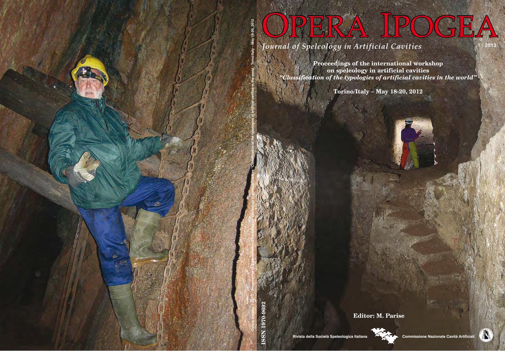
cover: eMiSSary oF neMi lake (latiuM)
(Photo carlo GerMani)
Back cover: Main StoPe at roSevale zennor tin Mine, cornwall (Great britain)
(Photo Martin Dixon)
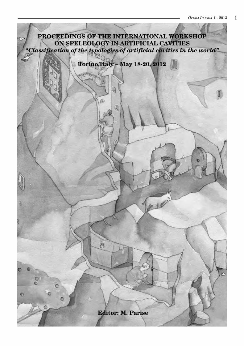
TiTle PaGe: “caPPaDocia”
(by roberto bixio)
PrinT:arti GraFiche eDitoriali S.r.l.
via Della Stazione, 41 - 61029 urbino (Pu) - tel. 0722328756
PaTronaGes
union internationale De SPeleoloGie
Società SPeleoloGica italiana
OPERA IPOGEA 1 - 2013 �
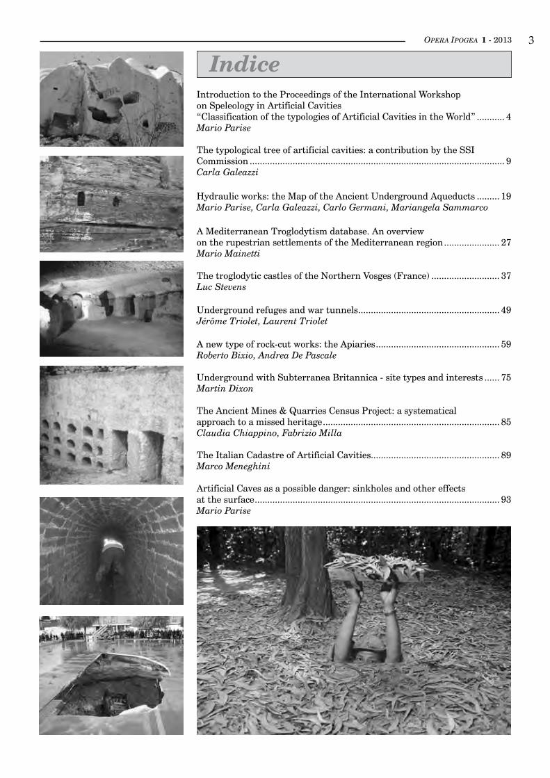
IndiceIntroduction to the Proceedings of the International Workshopon Speleology in Artificial Cavities“Classification of the typologies of Artificial Cavities in the World” ........... 4Mario Parise
The typological tree of artificial cavities: a contribution by the SSICommission ..................................................................................................... 9Carla Galeazzi
Hydraulic works: the Map of the Ancient Underground Aqueducts ......... 19Mario Parise, Carla Galeazzi, Carlo Germani, Mariangela Sammarco
A Mediterranean Troglodytism database. An overviewon the rupestrian settlements of the Mediterranean region ...................... 27Mario Mainetti
The troglodytic castles of the Northern Vosges (France) ........................... 37Luc Stevens
Underground refuges and war tunnels ........................................................ 49Jérôme Triolet, Laurent Triolet
A new type of rock-cut works: the Apiaries ................................................. 59Roberto Bixio, Andrea De Pascale
Underground with Subterranea Britannica - site types and interests ...... 75Martin Dixon
The Ancient Mines & Quarries Census Project: a systematicalapproach to a missed heritage ...................................................................... 85Claudia Chiappino, Fabrizio Milla
The Italian Cadastre of Artificial Cavities................................................... 89Marco Meneghini
Artificial Caves as a possible danger: sinkholes and other effectsat the surface ................................................................................................. 93Mario Parise
OPERA IPOGEA 1 - 2013�inTroducTion To THe ProceedinGs of THe inTernaTional WorksHoP
on sPeleoloGy in arTificial caviTies“classificaTion of THe TyPoloGies of arTificial caviTies in THe World”
Mario Parise
National Research Council of Italy, IRPI, Bari, Italy; [email protected] of Speleology in Artificial Cavities, Italian Speleological Society (SSI)
UIS Commission of Speleology in Artificial Cavities
The present special issue of Opera Ipogea is entirely dedicated to the International Workshop “Classification of the typologies of artificial cavities in the world”, that was held on May 17-20, 2012, in Torino (Italy), organized by the Commission on Artificial Cavities of the UIS. The venue was the prestigious Parco della Tesoriera, at the base of the Associazione Gruppi Speleologici Piemontesi.The Workshop, dedicated to the memory of Luigi Barcellari (Birci), was organized in agreement with the Commission on Artificial Cavities of the Italian Speleological Society, and with the logistic help of the local grotto Mus Muris.Some tens of participants, coming from five different countries attended the workshop, during which a dozen of invited lectures were presented, and ten posters displayed (see the lists at the end of this introduction), to illustra-te the most recent advancements about classification of artificial cavities, and about the study and documentation of the different categories of man-made caves.The UIS past president Arrigo Cigna welcomed the participants on behalf of UIS, and attended the whole workshop, significantly contributing to the discussions. A round table discussion, aimed at summarizing the ou-tcomes of the workshop, closed the theoretical part of the meeting. The last day of the Workshop was dedicated to the field visit to the sites of the Museum Pietro Micca and the 1706 Torino siege, including the 14-km long military underground gallery.The Workshop was the first occasion of meeting for the new UIS Commission on Artificial Cavities, that had been renovated following the 15th International Congress of Speleology at Kerrville (Texas, USA), and is now trying to give more attention within the caving world to issues dealing with speleology in artificial cavities. A further effort in this direction is the organization of a dedicated Special Session (“Speleological research and activities in artificial underground”) at the coming 16th International Congress of Speleology at Brno (Czech Republic), scheduled for July 2013.Going back to the issue you are reading, it comprises the papers presented as invited lectures at the workshop.The first contribution, intended as the introductory theme of the Workshop itself, was presented by Carla Galeazzi: she illustrates in the paper the typological tree of artificial cavities produced during long years of work by the Italian Commission, as a starting point to discuss the classification of artificial cavities, and eventually to modify it with further contributions from other countries.Entering then into more details about specific categories of artificial cavities, the contribution by Mario Parise, Carla Galeazzi, Carlo GerMani and MarianGela saMMarCo describes the main project of the Italian Commission, dedicated to create a register of the underground aqueducts in Italy, as well as of the other more significant un-derground hydraulic works.
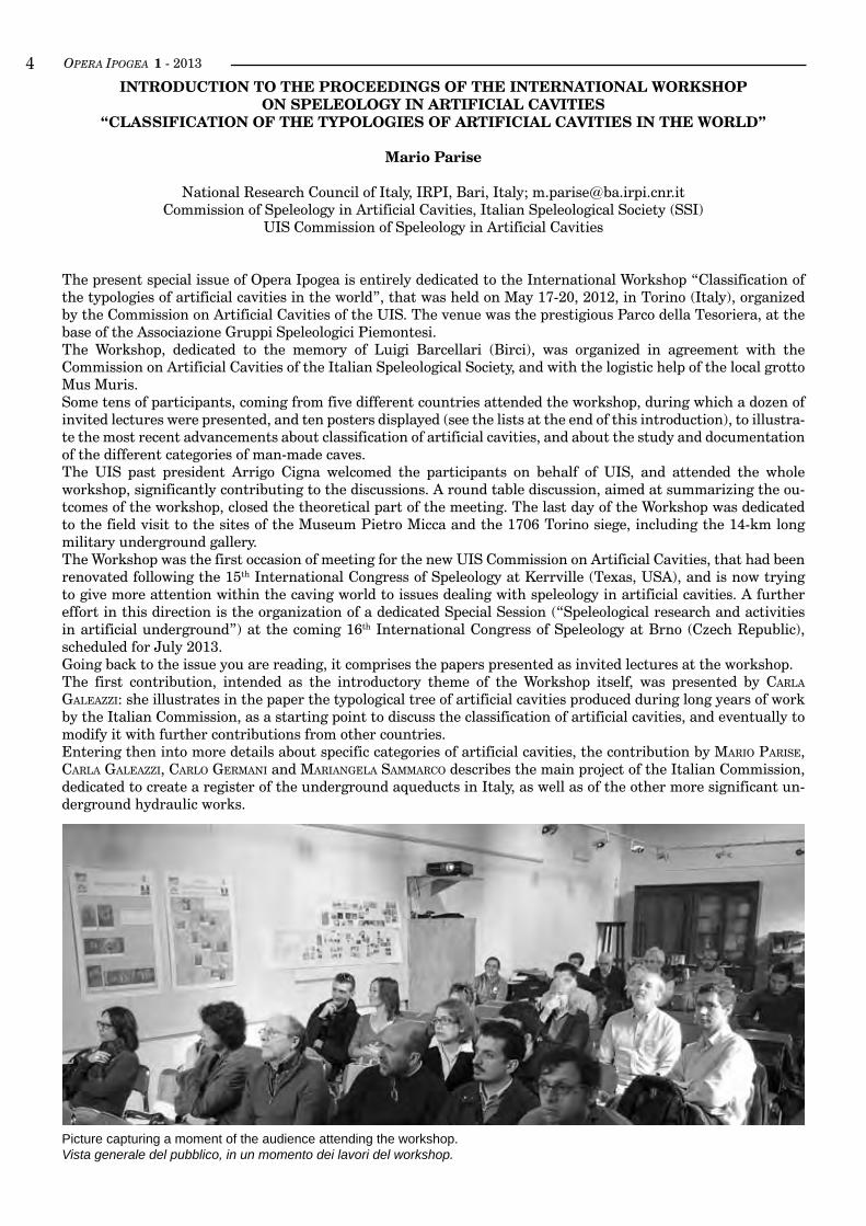
Picture capturing a moment of the audience attending the workshop.Vista generale del pubblico, in un momento dei lavori del workshop.
OPERA IPOGEA 1 - 2013 �
The project, active since 2003, has already been object of publication in a special issue of this same journal in 2007.Mario Mainetti presents a database about troglodytism in the Mediterranean Basin, as an attempt in putting to-gether, on a bibliographic basis, the many settlements distributed in the Mediterranean area. Its paper is followed by the work by luC stevens, dealing with the troglodytic castles at the boundaries between France (the northern Vosges) and Germany (Palatinat), that illustrates in details the artificial cavities realized in different epochs in several interesting case studies.Taking into account the category of military and war works, JeroMe and laurent triolet present a work dedicated to underground refuges and war tunnels, covering many different countries in the world, and showing the importance of military works in the fra-mework of the analysis of artificial caves. As a further contribution to integrate the classification of artificial cavities, roberto bixio and andrea de PasCale propo-se a new typology, consisting of apiaries; they describe many different types of apiaries, and illustrate them with experiences from different Mediterranean coun-tries.Martin dixon contributes to the special issue by brin-ging the UK viewpoint on artificial cavities, illustrating different typologies of caves examined by Subterranea Britannica. Claudia ChiaPPino and Fabrizio Milla de-scribe the recently started project about a census of ancient mines and underground quarries, in the at-tempt to provide data and information aimed at pos-sibly exploiting some of these abandoned structures, of great interest for industrial archaeology. MarCo MeneGhini, trustee of the Italian register of artificial cavities, illustrates the work so far done in collecting information about this cultural heritage in the whole Italian territory, and the modality to extract some in-
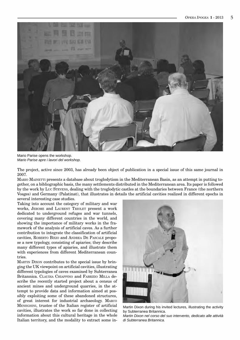
Mario Parise opens the workshop.Mario Parise apre i lavori del workshop.
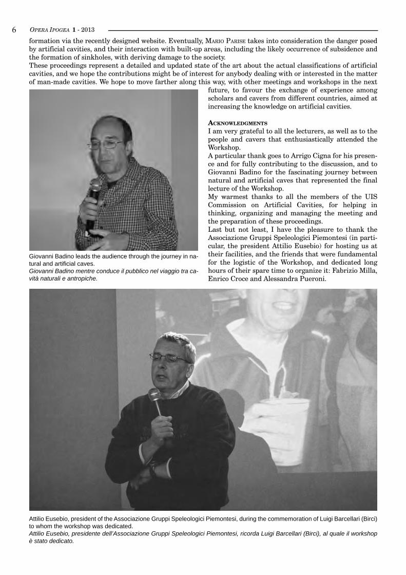
Martin Dixon during his invited lectures, illustrating the activity by Subterranea Britannica.Martin Dixon nel corso del suo intervento, dedicato alle attività di Subterranea Britannica.
OPERA IPOGEA 1 - 2013�formation via the recently designed website. Eventually, Mario Parise takes into consideration the danger posed by artificial cavities, and their interaction with built-up areas, including the likely occurrence of subsidence and the formation of sinkholes, with deriving damage to the society.These proceedings represent a detailed and updated state of the art about the actual classifications of artificial cavities, and we hope the contributions might be of interest for anybody dealing with or interested in the matter of man-made cavities. We hope to move farther along this way, with other meetings and workshops in the next
future, to favour the exchange of experience among scholars and cavers from different countries, aimed at increasing the knowledge on artificial cavities.
acknoWledGmenTs
I am very grateful to all the lecturers, as well as to the people and cavers that enthusiastically attended the Workshop.A particular thank goes to Arrigo Cigna for his presen-ce and for fully contributing to the discussion, and to Giovanni Badino for the fascinating journey between natural and artificial caves that represented the final lecture of the Workshop.My warmest thanks to all the members of the UIS Commission on Artificial Cavities, for helping in thinking, organizing and managing the meeting and the preparation of these proceedings.Last but not least, I have the pleasure to thank the Associazione Gruppi Speleologici Piemontesi (in parti-cular, the president Attilio Eusebio) for hosting us at their facilities, and the friends that were fundamental for the logistic of the Workshop, and dedicated long hours of their spare time to organize it: Fabrizio Milla, Enrico Croce and Alessandra Pueroni.
Giovanni Badino leads the audience through the journey in na-tural and artificial caves.Giovanni Badino mentre conduce il pubblico nel viaggio tra ca-vità naturali e antropiche.
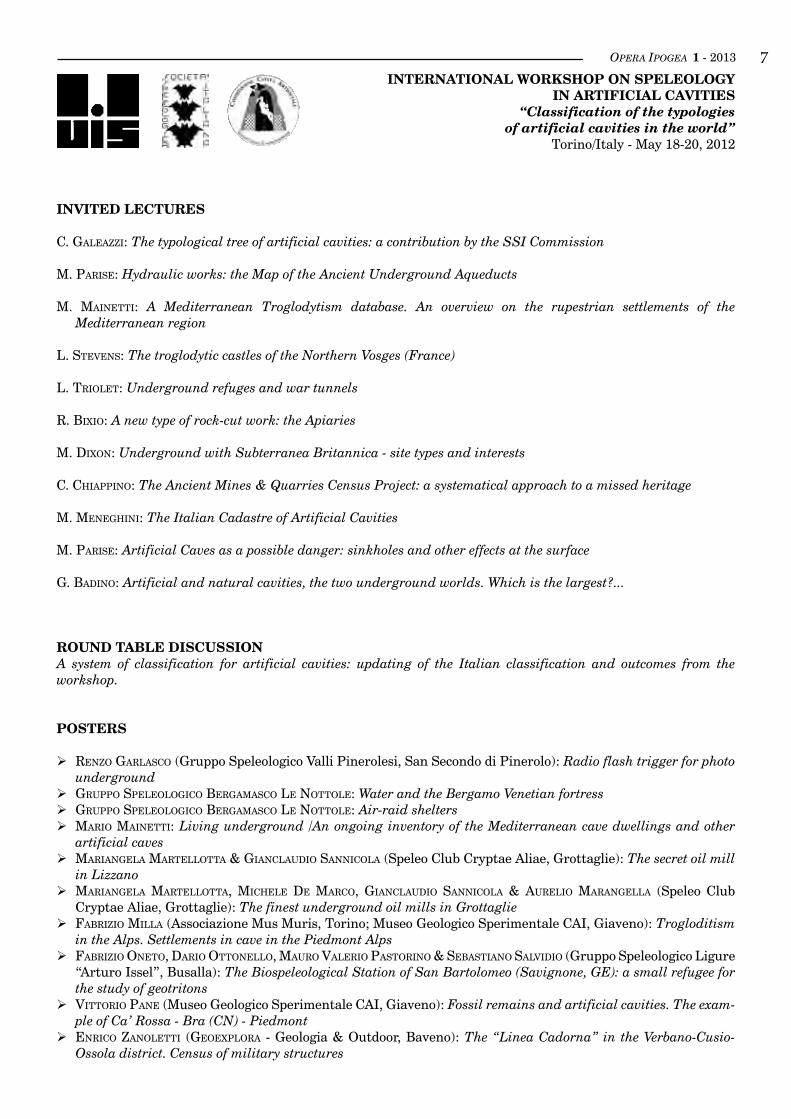
Attilio Eusebio, president of the Associazione Gruppi Speleologici Piemontesi, during the commemoration of Luigi Barcellari (Birci) to whom the workshop was dedicated.Attilio Eusebio, presidente dell’Associazione Gruppi Speleologici Piemontesi, ricorda Luigi Barcellari (Birci), al quale il workshop è stato dedicato.
OPERA IPOGEA 1 - 2013 �international workshoP on sPeleology
in artificial cavities“Classification of the typologies
of artificial cavities in the world”Torino/Italy - May 18-20, 2012
inviTed lecTures
C. Galeazzi: The typological tree of artificial cavities: a contribution by the SSI Commission
M. Parise: Hydraulic works: the Map of the Ancient Underground Aqueducts
M. Mainetti: A Mediterranean Troglodytism database. An overview on the rupestrian settlements of the Mediterranean region
L. stevens: The troglodytic castles of the Northern Vosges (France)
L. triolet: Underground refuges and war tunnels
R. bixio: A new type of rock-cut work: the Apiaries
M. dixon: Underground with Subterranea Britannica - site types and interests
C. ChiaPPino: The Ancient Mines & Quarries Census Project: a systematical approach to a missed heritage
M. MeneGhini: The Italian Cadastre of Artificial Cavities
M. Parise: Artificial Caves as a possible danger: sinkholes and other effects at the surface
G. badino: Artificial and natural cavities, the two underground worlds. Which is the largest?...
round table discussionA system of classification for artificial cavities: updating of the Italian classification and outcomes from the workshop.
PosTers
renzo GarlasCo (Gruppo Speleologico Valli Pinerolesi, San Secondo di Pinerolo): Radio flash trigger for photo underground
GruPPo sPeleoloGiCo berGaMasCo le nottole: Water and the Bergamo Venetian fortress GruPPo sPeleoloGiCo berGaMasCo le nottole: Air-raid shelters Mario Mainetti: Living underground /An ongoing inventory of the Mediterranean cave dwellings and other
artificial caves MarianGela Martellotta & GianClaudio sanniCola (Speleo Club Cryptae Aliae, Grottaglie): The secret oil mill
in Lizzano MarianGela Martellotta, MiChele de MarCo, GianClaudio sanniCola & aurelio MaranGella (Speleo Club
Cryptae Aliae, Grottaglie): The finest underground oil mills in Grottaglie Fabrizio Milla (Associazione Mus Muris, Torino; Museo Geologico Sperimentale CAI, Giaveno): Trogloditism
in the Alps. Settlements in cave in the Piedmont Alps Fabrizio oneto, dario ottonello, Mauro valerio Pastorino & sebastiano salvidio (Gruppo Speleologico Ligure
“Arturo Issel”, Busalla): The Biospeleological Station of San Bartolomeo (Savignone, GE): a small refugee for the study of geotritons
vittorio Pane (Museo Geologico Sperimentale CAI, Giaveno): Fossil remains and artificial cavities. The exam-ple of Ca’ Rossa - Bra (CN) - Piedmont
enriCo zanoletti (GeoexPlora - Geologia & Outdoor, Baveno): The “Linea Cadorna” in the Verbano-Cusio-Ossola district. Census of military structures

OPERA IPOGEA 1 - 2013�uis coMMission on artificial cavities
President: Mario Parise (Italy) - [email protected] President: Joep Orbons (Netherlands) - [email protected]: Carla Galeazzi (Italy) - [email protected]
Ordinary members: Roberto Bixio (Italy) Martin Dixon (Great Britain) HakanEğilmez(Turchia) Jean Francois Garnier (France) Jérôme Triolet (France) Laurent Triolet (France) Luc Stevens (Belgium) James McCarthy (Ireland)
OPERA IPOGEA 1 - 2013 �
1 Egeria Centro Ricerche Sotterranee ([email protected]; www.speleology.it)2 UIS Commission of Speleology in Artificial Cavities3 Italian Commission of Speleology in Artificial Cavities
inTroducTion: man and THe suBsoil
The use of underground natural spaces (caves) is as old as mankind. From prehistoric times man has devel-oped a culture of building that, from a simple adapta-
The typological tree of artificial cavities: a contribution by the Commission of the Italian Speleological SocietyCarla Galeazzi 1, 2, 3
Abstract
The variety of underground man-made structures is very large. Consequently, the classification chosen by the Commission of Artificial Cavities of the Italian Speleological Society to identify synthetically the nature of a cavity is organised like a tree, based on seven main types, in turn divided into sub-types. The use is made easy by alphanumeric codes. The typological classification of artificial cavities we use today, is due to the work of many colleagues during the last twenty-five years. In particular, in Italy Giulio Cappa and Paolo Guglia and in the international context Joep Orbons, Jêrome and Laurent Triolet, and Roberto Bixio deserve to be mentioned.In order to write this contribution, some basic texts on speleology in artificial cavities have been consulted: namely, lectures number 41, 42 and 43 of the didactic project of the SSI - UIS, the Speleology Notebook (Qua-derno di Speleologia) on artificial cavities published by the SSI in 2006, and the handbook (in press) of the National Course on Speleology in artificial cavities, organised by the SSI Commission in 2011 at Urbino.
key worDS: speleology in artificial cavities, typologies of artificial cavities, man-made underground structu-res, typological tree, classification.
Riassunto
L’aLbero tipoLogico deLLe cavità artificiaLi: iL contributo deLLa commissione nazionaLe ssi
In Italia, sin dalla costituzione del gruppo di studio della Società Speleologica Italiana denominato Com-missione Nazionale Cavità Artificiali, si è avvertita l’esigenza di procedere ad una suddivisione tipologica delle opere sotterranee di origine antropica. In altri paesi, dove probabilmente le tipologie di sotterranei oggetto di studio da parte di speleologi sono minori, viene utilizzata la sola distinzione fra grotte e cavità artificiali. Da noi la varietà delle strutture ipogee artificiali, con usi che spesso si sovrappongono nel corso dei secoli, ha richiesto la creazione di un albero tipologico che identificasse sinteticamente la natura delle cavità, basato su sette tipologie principali a loro volta suddivise in sotto-tipologie, indicate con codici alfa-numerici.La classificazione correntemente in uso è frutto del lavoro di molti colleghi nel corso degli ultimi venticinque anni: in particolare, in Italia Giulio Cappa e Paolo Guglia ed in ambito internazionale Joep Orbons, Jêrome e Laurent Triolet, Roberto Bixio.Il contributo qui pubblicato è frutto di una elaborazione di testi ritenuti fondamentali nello studio della speleologia in cavità artificiali: le lezioni numero 41, 42 e 43 del progetto didattico SSI, il Quaderno di Spe-leologia in cavità artificiali pubblicato dalla SSI nel 2006 ed il manuale del Corso Nazionale di Speleologia in cavità artificiali (in stampa) organizzato dalla Commissione SSI nel 2011 a Urbino.
Parole chiave: speleologia in cavità artificiali, tipologie cavità artificiali, albero tipologico, classificazione.
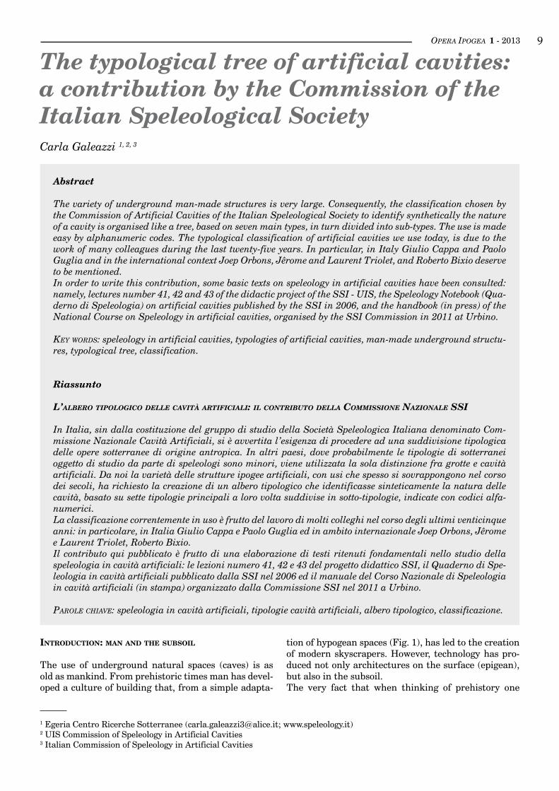
tion of hypogean spaces (Fig. 1), has led to the creation of modern skyscrapers. However, technology has pro-duced not only architectures on the surface (epigean), but also in the subsoil.The very fact that when thinking of prehistory one
OPERA IPOGEA 1 - 2013�0thinks of the caveman, shows how humanity, since its very beginning, has been familiar with the subsurface and the underground sites. It appears broadly plau-sible that prehistoric man was led into the ground in search of water and minerals, reasons that still after many millennia variously lead us to dig the earth.The beginnings of such activities date back to very re-mote times. Australian aborigines, at a level of develop-ment similar to the European Palaeolithic, had already dug deep galleries to find water and mines for the ex-traction of flint, known since the early Neolithic.So initially they dug to extract pigments (red ochre) and flint cores to be transformed into tools. Then, dur-ing the Copper age (3,500 to 2,500 B.C.), man used the techniques of excavation to capture underground wa-ter veins (especially in the arid North African or Asian regions) and for mining purposes (for example, copper and iron mines in Etruria, Latium, Italy).In Italy between the eighth and sixth centuries B.C., the work of excavation became frenetic: in Latium alone, the number of cavities made in that period is estimated at several thousand. Digging the soil to ex-tract what is necessary for survival, man discovers that he can find shelter from the natural elements in the cavities so obtained, exactly as in a cave. Therefore, the
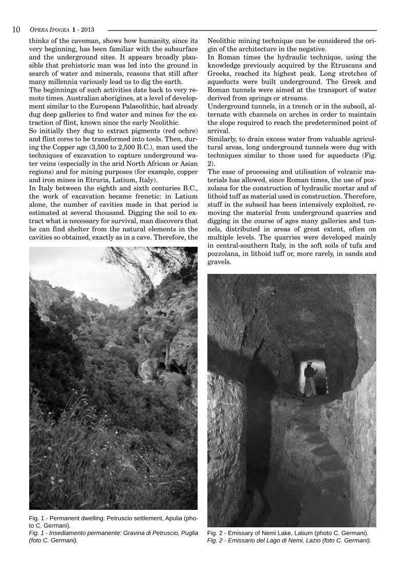
Neolithic mining technique can be considered the ori-gin of the architecture in the negative.In Roman times the hydraulic technique, using the knowledge previously acquired by the Etruscans and Greeks, reached its highest peak. Long stretches of aqueducts were built underground. The Greek and Roman tunnels were aimed at the transport of water derived from springs or streams.Underground tunnels, in a trench or in the subsoil, al-ternate with channels on arches in order to maintain the slope required to reach the predetermined point of arrival.Similarly, to drain excess water from valuable agricul-tural areas, long underground tunnels were dug with techniques similar to those used for aqueducts (Fig. 2).The ease of processing and utilisation of volcanic ma-terials has allowed, since Roman times, the use of poz-zolana for the construction of hydraulic mortar and of lithoid tuff as material used in construction. Therefore, stuff in the subsoil has been intensively exploited, re-moving the material from underground quarries and digging in the course of ages many galleries and tun-nels, distributed in areas of great extent, often on multiple levels. The quarries were developed mainly in central-southern Italy, in the soft soils of tufa and pozzolana, in lithoid tuff or, more rarely, in sands and gravels.
Fig. 1 - Permanent dwelling: Petruscio settlement, Apulia (pho-to C. Germani).Fig. 1 - Insediamento permanente: Gravina di Petruscio, Puglia (foto C. Germani).
Fig. 2 - Emissary of Nemi Lake, Latium (photo C. Germani).Fig. 2 - Emissario del Lago di Nemi, Lazio (foto C. Germani).
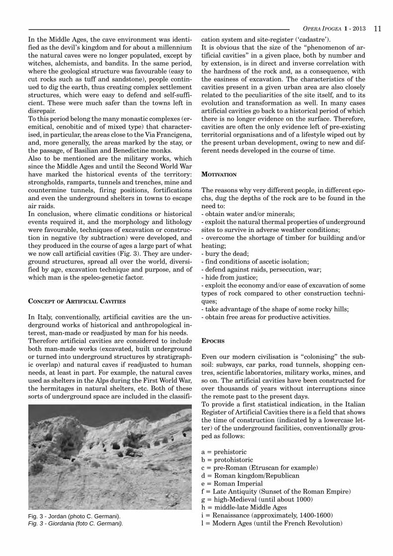
OPERA IPOGEA 1 - 2013 ��In the Middle Ages, the cave environment was identi-fied as the devil’s kingdom and for about a millennium the natural caves were no longer populated, except by witches, alchemists, and bandits. In the same period, where the geological structure was favourable (easy to cut rocks such as tuff and sandstone), people contin-ued to dig the earth, thus creating complex settlement structures, which were easy to defend and self-suffi-cient. These were much safer than the towns left in disrepair.To this period belong the many monastic complexes (er-emitical, cenobitic and of mixed type) that character-ised, in particular, the areas close to the Via Francigena, and, more generally, the areas marked by the stay, or the passage, of Basilian and Benedictine monks.Also to be mentioned are the military works, which since the Middle Ages and until the Second World War have marked the historical events of the territory: strongholds, ramparts, tunnels and trenches, mine and countermine tunnels, firing positions, fortifications and even the underground shelters in towns to escape air raids.In conclusion, where climatic conditions or historical events required it, and the morphology and lithology were favourable, techniques of excavation or construc-tion in negative (by subtraction) were developed, and they produced in the course of ages a large part of what we now call artificial cavities (Fig. 3). They are under-ground structures, spread all over the world, diversi-fied by age, excavation technique and purpose, and of which man is the speleo-genetic factor.
concePT of arTificial caviTies
In Italy, conventionally, artificial cavities are the un-derground works of historical and anthropological in-terest, man-made or readjusted by man for his needs.Therefore artificial cavities are considered to include both man-made works (excavated, built underground or turned into underground structures by stratigraph-ic overlap) and natural caves if readjusted to human needs, at least in part. For example, the natural caves used as shelters in the Alps during the First World War, the hermitages in natural shelters, etc. Both of these sorts of underground space are included in the classifi-
cation system and site-register (‘cadastre’).It is obvious that the size of the “phenomenon of ar-tificial cavities” in a given place, both by number and by extension, is in direct and inverse correlation with the hardness of the rock and, as a consequence, with the easiness of excavation. The characteristics of the cavities present in a given urban area are also closely related to the peculiarities of the site itself, and to its evolution and transformation as well. In many cases artificial cavities go back to a historical period of which there is no longer evidence on the surface. Therefore, cavities are often the only evidence left of pre-existing territorial organisations and of a lifestyle wiped out by the present urban development, owing to new and dif-ferent needs developed in the course of time.
moTivaTion
The reasons why very different people, in different epo-chs, dug the depths of the rock are to be found in the need to:- obtain water and/or minerals;- exploit the natural thermal properties of underground sites to survive in adverse weather conditions;- overcome the shortage of timber for building and/or heating;- bury the dead;- find conditions of ascetic isolation;- defend against raids, persecution, war;- hide from justice;- exploit the economy and/or ease of excavation of some types of rock compared to other construction techni-ques;- take advantage of the shape of some rocky hills;- obtain free areas for productive activities.
ePocHs
Even our modern civilisation is “colonising” the sub-soil: subways, car parks, road tunnels, shopping cen-tres, scientific laboratories, military works, mines, and so on. The artificial cavities have been constructed for over thousands of years without interruptions since the remote past to the present days.To provide a first statistical indication, in the Italian Register of Artificial Cavities there is a field that shows the time of construction (indicated by a lowercase let-ter) of the underground facilities, conventionally grou-ped as follows:
a = prehistoricb = protohistoricc = pre-Roman (Etruscan for example)d = Roman kingdom/Republicane = Roman Imperialf = Late Antiquity (Sunset of the Roman Empire)g = high-Medieval (until about 1000)h = middle-late Middle Agesi = Renaissance (approximately, 1400-1600)l = Modern Ages (until the French Revolution)
Fig. 3 - Jordan (photo C. Germani).Fig. 3 - Giordania (foto C. Germani).
OPERA IPOGEA 1 - 2013��m = XIX centuryn = XX century and later
sTudy and classificaTion of arTificial caviTies
To ensure the proper investigation and cataloguing of anthropogenic cavities it is crucial to identify:- the technique of construction;- the function (or purpose);- the time of excavation;- the shape and development of the underground struc-ture;- the spatial correlation with the surrounding environ-ment;- the temporal correlation with the general historical events on a general, regional and local scale.
ParT one: caTeGories
A first broad general subdivision is based on the con-struction technique. In turn, each category is classified (see: part two, Types) with respect to the use for which each structure was, or is, used.
Techniques of construction- cavities dug in the subsoil;- cavities constructed in the subsoil;- cavities obtained by re-covering;- anomalous artificial cavities;- mixed artificial cavities;- natural caves modified by men.
Cavities dug in the subsoil. These are underground structures in the strict sense: rooms obtained by re-moving stone materials (rocks) under the surface level, or inside rocky hills, or carved close to the surface of the cliff faces, canyons, ravines (for example, troglo-dytic structures).
Cavities constructed in the subsoil. Excavation in trenches is realised with an open air excavation, fol-lowed by the dressing of the walls and the construction of the vault. Excavation in gallery is realised by remov-ing the rock entirely underground. The walls are then coated with different masonry techniques.
Re-covered cavities. Often in urban areas human activ-ity produces the covering, natural or artificial, of struc-tures originally located on the surface.
Anomalous artificial cavities. These structures are built on the surface, but with characteristics similar to those underground (for example, some military bunkers).
Mixed artificial cavities. They are the result of the dig-ging to reach, extend or alter natural caves.
Caves with anthropogenic interventions. Natural caves that have undergone limited human interventions. They represent the boundary between the natural cav-
ities and those of artificial origin (anthropogenic). In general, they are structures with limited extent, within which man has built housing and/or has dedicated the cave to the cult: a cave-shrine.
ParT TWo: TyPes
According to the function (intended use) for which an artificial cavity was, or is still, used it has been estab-lished a classification into types, regardless of the con-struction techniques (“categories” described above).
TyPoloGical Tree
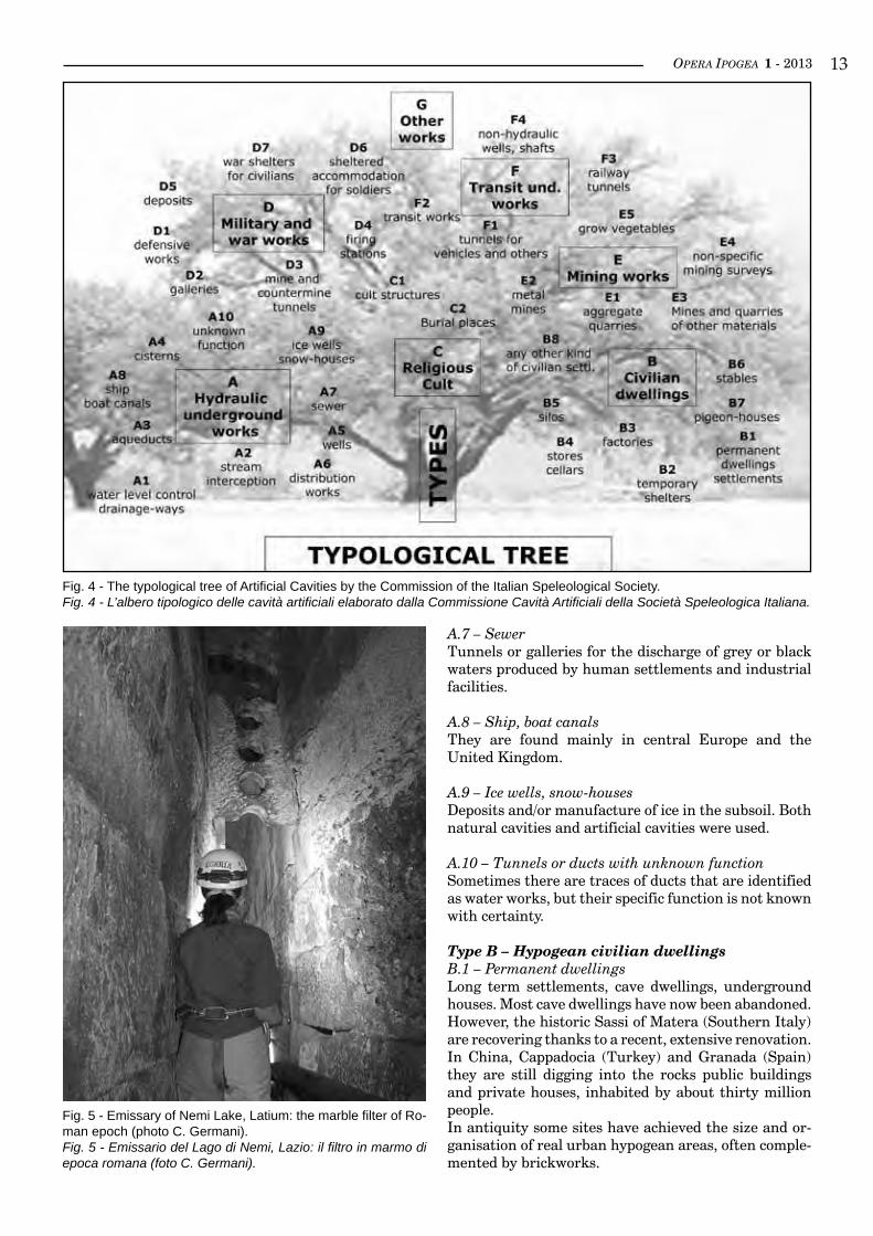
The variety of underground artificial structures is very large. Consequently, the classification chosen by the Commission of Artificial Cavities of the Italian Speleological Society to identify synthetically the na-ture of a cavity is organised like a tree, based on seven main types, in turn divided into sub-types (Fig. 4). The use is made easy by alphanumeric codes. Often differ-ent uses overlap in time; thus, a single site may have multiple classifications representing different periods in its life.
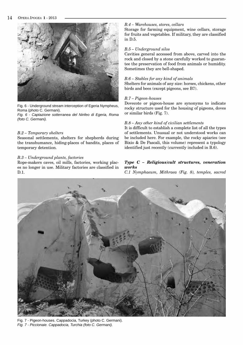
Type A – Hydraulic underground worksA.1 – Water level control, drainage-waysTunnels dug for the reclamation of marshlands and to stabilise the level of lakes (emissaries; Fig. 5) and res-ervoirs.
A.2 – Underground stream interception structuresTunnels and galleries designed to capture underground water veins or dripping waters (Fig. 6). The work of in-terception can consist either of a simple duct cut into the rock, or of a complex system integrated with build-ing works.
A.3 – Underground water ducts: aqueductsGalleries and tunnels to carry water from the stream interceptions or other body of water to the users. Deviations into galleries of water courses can allow the construction of bridges: the so-called Ponti Terra or Ponti Sodi (Etruscan technique).
A.4 – Cisterns, water reservoirsUnderground spaces to store water, usually completed with waterproofing of the walls.
A.5 – WellsVertical drilling to reach the drinking water and carry water to the surface. Those located within other un-derground structures are considered an integral part thereof.
A.6 – Hydraulic distribution worksTanks or other underground rooms in which one or more ducts converge and from which other ducts go out to distribute water to the users (castellum aquae).
OPERA IPOGEA 1 - 2013 ��
Fig. 4 - The typological tree of Artificial Cavities by the Commission of the Italian Speleological Society.Fig. 4 - L’albero tipologico delle cavità artificiali elaborato dalla Commissione Cavità Artificiali della Società Speleologica Italiana.
A.7 – SewerTunnels or galleries for the discharge of grey or black waters produced by human settlements and industrial facilities.
A.8 – Ship, boat canalsThey are found mainly in central Europe and the United Kingdom.
A.9 – Ice wells, snow-housesDeposits and/or manufacture of ice in the subsoil. Both natural cavities and artificial cavities were used.
A.10 – Tunnels or ducts with unknown functionSometimes there are traces of ducts that are identified as water works, but their specific function is not known with certainty.
Type B – Hypogean civilian dwellingsB.1 – Permanent dwellingsLong term settlements, cave dwellings, underground houses. Most cave dwellings have now been abandoned. However, the historic Sassi of Matera (Southern Italy) are recovering thanks to a recent, extensive renovation. In China, Cappadocia (Turkey) and Granada (Spain) they are still digging into the rocks public buildings and private houses, inhabited by about thirty million people.In antiquity some sites have achieved the size and or-ganisation of real urban hypogean areas, often comple-mented by brickworks.
Fig. 5 - Emissary of Nemi Lake, Latium: the marble filter of Ro-man epoch (photo C. Germani).Fig. 5 - Emissario del Lago di Nemi, Lazio: il filtro in marmo di epoca romana (foto C. Germani).
OPERA IPOGEA 1 - 2013��
B.2 – Temporary sheltersSeasonal settlements, shelters for shepherds during the transhumance, hiding-places of bandits, places of temporary detention.
B.3 – Underground plants, factoriesRope-makers caves, oil mills, factories, working plac-es no longer in use. Military factories are classified in D.1.
B.4 – Warehouses, stores, cellarsStorage for farming equipment, wine cellars, storage for fruits and vegetables. If military, they are classified in D.5.
B.5 – Underground silosCavities general accessed from above, carved into the rock and closed by a stone carefully worked to guaran-tee the preservation of food from animals or humidity. Sometimes they are bell-shaped.
B.6 – Stables for any kind of animalsShelters for animals of any size: horses, chickens, other birds and bees (except pigeons, see B7).
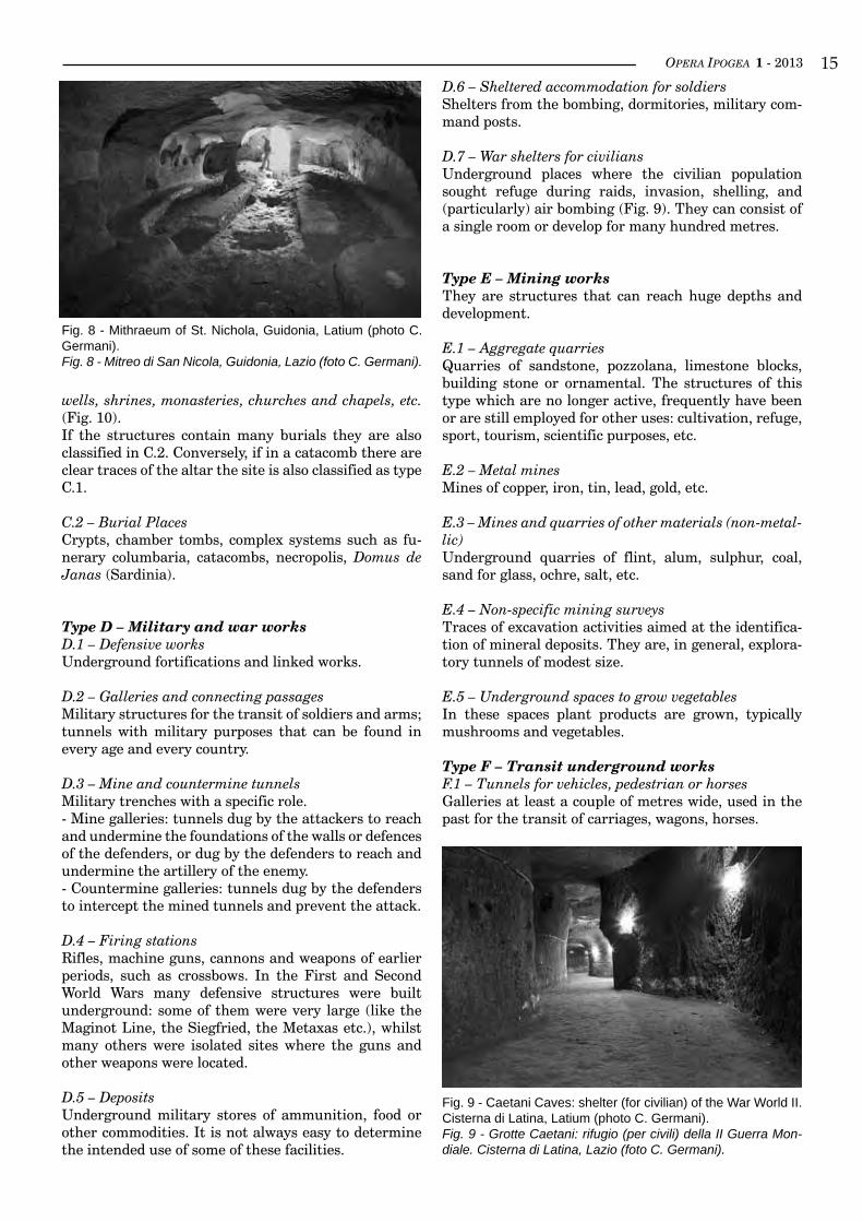
B.7 – Pigeon-housesDovecote or pigeon-house are synonyms to indicate rocky structure used for the housing of pigeons, doves or similar birds (Fig. 7).
B.8 – Any other kind of civilian settlementsIt is difficult to establish a complete list of all the types of settlements. Unusual or not understood works can be included here. For example, the rocky apiaries (see Bixio & De Pascali, this volume) represent a typology identified just recently (currently included in B.6).
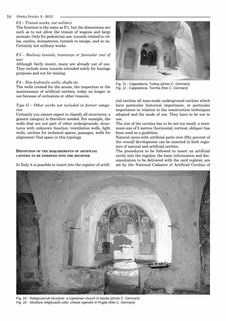
Type C – Religious/cult structures, veneration worksC.1 Nymphaeum, Mithraea (Fig. 8), temples, sacred
Fig. 6 - Underground stream interception of Egeria Nympheus, Roma (photo C. Germani).Fig. 6 - Captazione sotterranea del Ninfeo di Egeria, Roma (foto C. Germani).
Fig. 7 - Pigeon-houses. Cappadocia, Turkey (photo C. Germani).Fig. 7 - Piccionaie. Cappadocia, Turchia (foto C. Germani).
OPERA IPOGEA 1 - 2013 ��
wells, shrines, monasteries, churches and chapels, etc. (Fig. 10).If the structures contain many burials they are also classified in C.2. Conversely, if in a catacomb there are clear traces of the altar the site is also classified as type C.1.
C.2 – Burial PlacesCrypts, chamber tombs, complex systems such as fu-nerary columbaria, catacombs, necropolis, Domus de Janas (Sardinia).
Type D – Military and war worksD.1 – Defensive worksUnderground fortifications and linked works.
D.2 – Galleries and connecting passagesMilitary structures for the transit of soldiers and arms; tunnels with military purposes that can be found in every age and every country.
D.3 – Mine and countermine tunnels Military trenches with a specific role.- Mine galleries: tunnels dug by the attackers to reach and undermine the foundations of the walls or defences of the defenders, or dug by the defenders to reach and undermine the artillery of the enemy. - Countermine galleries: tunnels dug by the defenders to intercept the mined tunnels and prevent the attack.
D.4 – Firing stationsRifles, machine guns, cannons and weapons of earlier periods, such as crossbows. In the First and Second World Wars many defensive structures were built underground: some of them were very large (like the Maginot Line, the Siegfried, the Metaxas etc.), whilst many others were isolated sites where the guns and other weapons were located.
D.5 – DepositsUnderground military stores of ammunition, food or other commodities. It is not always easy to determine the intended use of some of these facilities.
D.6 – Sheltered accommodation for soldiersShelters from the bombing, dormitories, military com-mand posts.
D.7 – War shelters for civiliansUnderground places where the civilian population sought refuge during raids, invasion, shelling, and (particularly) air bombing (Fig. 9). They can consist of a single room or develop for many hundred metres.
Type E – Mining worksThey are structures that can reach huge depths and development.
E.1 – Aggregate quarriesQuarries of sandstone, pozzolana, limestone blocks, building stone or ornamental. The structures of this type which are no longer active, frequently have been or are still employed for other uses: cultivation, refuge, sport, tourism, scientific purposes, etc.
E.2 – Metal minesMines of copper, iron, tin, lead, gold, etc.
E.3 – Mines and quarries of other materials (non-metal-lic)Underground quarries of flint, alum, sulphur, coal, sand for glass, ochre, salt, etc.
E.4 – Non-specific mining surveysTraces of excavation activities aimed at the identifica-tion of mineral deposits. They are, in general, explora-tory tunnels of modest size.
E.5 – Underground spaces to grow vegetablesIn these spaces plant products are grown, typically mushrooms and vegetables.
Type F – Transit underground worksF.1 – Tunnels for vehicles, pedestrian or horsesGalleries at least a couple of metres wide, used in the past for the transit of carriages, wagons, horses.
Fig. 8 - Mithraeum of St. Nichola, Guidonia, Latium (photo C. Germani).Fig. 8 - Mitreo di San Nicola, Guidonia, Lazio (foto C. Germani).
Fig. 9 - Caetani Caves: shelter (for civilian) of the War World II. Cisterna di Latina, Latium (photo C. Germani).Fig. 9 - Grotte Caetani: rifugio (per civili) della II Guerra Mon-diale. Cisterna di Latina, Lazio (foto C. Germani).
OPERA IPOGEA 1 - 2013��
Fig. 10 - Religious/cult structure: a rupestrian church in Apulia (photo C. Germani).Fig. 10 - Struttura religiosa/di culto: chiesa rupestre in Puglia (foto C. Germani).
F.2 – Transit works, not militaryThe function is the same as F.1, but the dimensions are such as to not allow the transit of wagons and large animals. Only for pedestrian use: tunnels related to vil-las, castles, monasteries, tunnels to escape, and so on. Certainly not military works.
F.3 – Railway tunnels, tramways or funicular (out of use)Although fairly recent, many are already out of use. They include mine tunnels intended solely for haulage purposes and not for mining.
F.4 – Non-hydraulic wells, shafts etc.The wells created for the access, the inspection or the maintenance of artificial cavities, today no longer in use because of occlusions or other reasons.
Type G – Other works not included in former catego-riesCertainly you cannot expect to classify all structures: a generic category is therefore needed. For example, the wells that are not part of other undergrounds, struc-tures with unknown function (ventilation wells, light wells, cavities for technical spaces, passages, wells for alignment) find space in this typology.
definiTion of THe requiremenTs of arTificial
caviTies To Be inserTed inTo THe reGisTer
In Italy it is possible to insert into the register of artifi-
cial cavities all man-made underground cavities which have particular historical importance, or particular importance in relation to the construction techniques adopted and the mode of use. They have to be not in use. The size of the cavities has to be not too small: a mini-mum size of 5 metres (horizontal, vertical, oblique) has been used as a guideline.Natural caves with artificial parts over fifty percent of the overall development can be inserted in both regis-ters of natural and artificial cavities.The procedures to be followed to insert an artificial cavity into the register, the basic information and doc-umentation to be delivered with the card register, are set by the National Cadastre of Artificial Cavities of
Fig. 11 - Cappadocia, Turkey (photo C. Germani).Fig. 11 - Cappadocia, Turchia (foto C. Germani).
OPERA IPOGEA 1 - 2013 ��
bibliography
AA.VV., 1985, Roma sotterranea, Ed. Fratelli Palombi, Roma.AA.VV., 1986, Il trionfo dell’ acqua. Acque ed acquedotti a Roma, Ed. Paliani, Roma.AA.VV., 1987, Le cavità artificiali aspetti storico-morfologici e loro utilizzo, Atti II Convegno Nazionale di Speleologia
Urbana, CAI Napoli.AA.VV., 1991, Gli Etruschi maestri di idraulica, Electa Ed. Umbri, Perugia.AA.VV., 1991, 3rd International symposium on underground quarries, CAI Napoli.AA.VV., 1993, Actes du symposium international consacré au patrimoine souterrain creusé, Centre d’Etudes et de Pro-
motion du Patrimoine Souterrain Creusé, J. Rewerski Ed., Saumur (France).AA.VV., 1993, Proc. Int. Conf. on karez irrigation.AA.VV., 1997, Proc. of IV Nat. Conf. “Le Cavità Artificiali”, Trieste.AA.VV., 1999, Proc. Nat. Conf. “La Memoria del sottosuolo”, Camerano (Ancona).AA.VV., 1999, In Binos Actus Lumina, Vol. I, Proc. Int. Conf. “Metodologie per lo studio della scienza idraulica antica”,
Ravenna, Agorà Ed., 2002.AA.VV., 2001, In Binos Actus Lumina, Vol. II, Proc. Int. Conf. “Archeologia e società. L’idraulica degli antichi tra pas-
sato e futuro”, Narni, Agorà Ed., 2005.ashby T., 1935, The Aqueducts of ancient Rome, Clarendon Press, Oxford 1991.bertuCCi, G., bixio r., traverso M., (eds), 1995, Le città sotterranee della Cappadocia. Erga Edizioni Genova, 140 pp.bixio r., Galeazzi C. (eds), 2009, Artificial Cavities Lessons no. 41, 42, 43. Didactic Project SSI-UIS.brisse a., de rotrou. L, 1876, The drainage of the Lake Fucino. Ed. Propaganda Press, Roma.burri E., 1988, Proposta di simbologia per la redazione di carte tematiche in tema di cavità artificiali. Boll. Ass. Ital.
Cartografia, 72, p. 163.burri E., 1989, Les canalizations artificielles antique et souterraines pour la bonification et le regime des terrains agrai-
res, l’irrigation et l’approvisionnement hydrique des eaux lacustre dans l’Italie centrale. Proc. Ist Int. Congress of Subterraneologie.
Caloi v., Castellani, V., 1985, Origine e sviluppo dell’opera cunicolare nel mondo antico. Proc. Nat. Conf. “Le Cavità Artificiali”, Napoli.
CaPPa G., 2006, Quaderno di Speleologia in cavità artificiali. Quaderni Didattici SSI, 4, 20 pp.CaPolonGo D., 1972, Ricerche nei qanat dell’Italia Meridionale. Boll. Soc. Entomol., 104, pp. 59-62.Castellani V., 1982, Speleologia e cavità artificiali. Proc. Conf. of Narni, pp. 9-11.Castellani V., 1994, I Rhettara del Tafilalt. Proc. XVII Nat. Conf. of Speleology.Castellani V., 1994, Evidences for hydrogeological planning in ancient Cappadocia. Journal of Ancient Topography, 3,
207.Castellani V., 1995, From ancient “qanats” to present “rhettaras” in the oases of Moroccan Sahara. UNESCO Int.
Symp. “Proper uses of natural Resources”, Matera.Castellani V., 2000, La Civiltà dell’acqua. Editorial Service System, Roma.Castellani v., bixio R., 1995, Underground settlement and hydrogeological planning in ancient Cappadocia. UNESCO
Int. Symp. “Proper uses of natural Resources”, Matera.Castellani v., bixio R., 1995, New tipologies of cappadocian underground: the redoubts and the hydric installations.
XVII Int. Symp. of Excavation, Surveys and Archeometry, Ankara.Castellani v., bixio R., 1995, Categories of hypogean Cappadocian structures. Int. Symp. on Souterrains, Maastricht.Castellani v., Caloi V., 1982, Il catasto della Cavità Artificiali strumento per la conoscenza dell’evoluzione storica e
ambientale del territorio. Proc. Nat. Conf. Narni.Castellani v., draGoni W., 1990, Contribution to the history of undergrond structures: ancient Roman tunnels in central
Italy. Int. Symp. Uniq. Undergr. Structures, Denver (Colorado, USA).Castellani v., draGoni W., 1991, Italian tunnels in antiquity. Tunnels and Tunnelling, vol. 23 pp. 55-58.Castellani v., draGoni W., 1992, Opere arcaiche per il controllo del territorio: gli emissari artificiali dei laghi albani. In:
“Gli Etruschi Maestri di Idraulica”, Electa Edizioni, Perugia, pp. 43-60.Castellani v., draGoni W., 1997, Ancient tunnels: from Roman outlets back to early Greek civilization. XII Int. Congress
of Speleology, La Chaux-de-Fonds (Switzerland), vol. 3, pp. 269.Castellani v., Mantellini S., 2003, Water management at Pantelleria in Punic-Roman Times. International Conference
“Arid Lands in Roman Times”, University of Rome “La Sapienza”, Roma.
SSI. Any additional data relating to the artificial cavi-ties can be reported and must always be taken into ac-count by the Coordinator of the Register at the time of archiving and data management.
ProPosal for adoPTion of sTandard symBols in sur-veyinG and maPPinG of arTificial caviTies.
For many years UIS has been adopting schemes of ref-
erence both for the mapping of caves and for the indica-tions relating to the karstic surface phenomena.Similarly, it would be very important to encode the most suitable graphic symbols to represent the artifi-cial cavities, comparing and sharing those already in use in different countries.In particular, it would be interesting to include the in-dication of the artificial wells (water, light, ventilation wells), the magnetic north, the direction of excavation, the direction of water flow, etc.
OPERA IPOGEA 1 - 2013��
Cuneo P., 1981, Urbanistica ed ambiente architettonico della Cappadocia. In: Le aree omogenee della Civiltà Rupestre nell’ambito dell’Impero Bizantino: la Cappadocia, Proc. V Int. Conf. “La civiltà rupestre medievale nel mezzogiorno d’Italia”, Galatina, pp. 199-203.
de anGelis d’ossat G.,1933, Antiche opere di risanamento idraulico delle terre presso Roma. Da Vinci Ed., Roma, p. 69.
del Pelo Pardi G., 1943, Bonifiche antichissime. La malaria ed i cunicoli del Lazio. Atti R. Accademia Georgofili, Firenze.
del Pelo Pardi T., 1969, I cunicoli del Lazio. Sigma Tau.Frederiksen M.W., Ward-Perkins J.B., 1957, The ancient road system of the central and northern Ager Faliscus. Papers
British School at Rome.Ghedini F., rosada G., 1993, Il sottosuolo nel mondo antico. Progetto Quarta Dimensione, Ed. Canova, Treviso. GreWe K., 1986, Zur geschichte des wasserleitungstunnels. Antike Welt.Grewe K., 1998, Licht am ende des Tunnels. Planung und Trassierung im antike n Tunnelbau, Von Zabern Verlag,
Mainz am Rhein.Golab L.W., 1951, A study of irrigation in east Turkestan. Anthropos, vol. 46, pp. 187-199.Judson S., kahane A., 1963, Underground drainageways in southern Etruria. Papers of the British School at Rome,
vol. 31, pp. 74-99.kienast H.J., 1996, Samos. Rudolf Habelt GmBH, Bonn.kloner A., 1991, A burial cave from the early Roman period at Giv’at Seled in the Judean Shephelah”. Atiqot, vol. 20,
pp. 159-163.kloner A., saGiv N., 1993,The olive presses of Hellenistic Maresha Israel. In: M.C. aMouretti and J.P. brun, eds., Oil
and Wine Production in the Mediterranean Area, Bulletin de Correspondance Hellenique, Suppl. 26, Athens and Paris, pp. 119-136.
kloner A., 1997, Underground metropolis: the subterranean world of Maresha. Biblical Archaeological Rev. 23, 24.kloner A., zissu B., 2009, Underground hiding complexes in Israel and the Bar Kokhba Revolt, Opera Ipogea 1/2009,
Italian Speleological Society, pp. 9-28.lanCiani R., 1909, Wandering in the Roman campaign. Boston 1980.liGhtFoot D. R., 2000, The origin and diffusion of qanats in Arabia: new evidence from the northern and southern pe-
ninsula. Geographycal Journal, 166 (3), pp. 215-226.Parise M., 2009, Distribution and characteristics of ancient underground aqueducts in Italy. Proc. Int. Water Associa-
tion Specialty Conf., 2nd Int. Symp. on Water and Wastewater Technologies in Ancient Civilizations, Bari.Parise M., bixio r., burri e., Caloi v., del Prete s., Galeazzi C., GerMani C., GuGlia P., MeneGhini M., saMMarCo M.,
2009, The map of ancient underground aqueducts: a nation-wide project by the Italian Speleological Society. Proc. 15th Int. Cong. of Speleology, Kerrville (Texas, USA), vol. 3, pp. 2027-2031.
Parise M., 2012, Underground aqueducts: a first preliminary bibliography around the world. 3rd IWA Specialized Con-ference on Water and Wastewater Technologies in Ancient Civilizations, Instanbul (Turkey), 22-24 March 2012, pp. 65-72.
shaW B.D., 1984, Water and society in the ancient Maghreb: technology, property and development. Antiquités Africai-nes, vol. 20, CNRS, Paris.
tanner R.G., 1987, Philosophical and cultural concepts underlying water supply in Antiquity. IAHS Pub. 164.tölle-kastenbein R., 1990, Antike wasserkultur. Münken.triolet J., L., 1995, Les souterrains, le monde des souterrains-refuges en France. Editions Errance, Paris.triolet J., L., 2002, Souterrains et croyances. Editions Ouest-France, Rennes.triolet L., 2005, Le troglodytes de sud ouest. Edition Alan Sutton, Saint-Cyr-sur-Loire.triolet J., L., 2011, La guerre souterrain. Edition Perrains, Paris, 348 pp.WulFF H.E., 1968, The qanats of Iran. Sc. Am., vol. 218, pp. 94-105.
OPERA IPOGEA 1 - 2013 ��
1 National Research Council of Italy, IRPI, Bari, Italy; [email protected] UIS Commission of Speleology in Artificial Cavities3 Commission of Speleology in Artificial Cavities, Italian Speleological Society (SSI)4 Egeria Underground Research Center (www.speleology.it), e-mail: [email protected] University of Salento, Lecce, Italy
Abstract
Among the many different typologies of artificial caves, hydraulic works deserve a particular attention, being strongly related to past history and civilization. Without the availability of water, development of settlements and villages, and establishment of a geographically stable inhabited area were not possible. Starting from these considerations, in 2003 the Commission on Artificial Cavities of the Italian Speleological Society star-ted the Project “The Map of Ancient Underground Aqueducts in Italy”. Italy presents on its territory a huge amount of hydraulic works, showing very long underground stretches, that represent a valuable documentation of the skill and engineering techniques of the ancient communities. Due to their mostly underground development, they have often been preserved intact for millennia. During these years of work, we have been able to collect a great amount of material and information about under-ground aqueducts, through both direct caving explorations and analysis of the available documentation; a detailed register of ancient underground aqueducts in Italy has been thus realized, aimed at safeguarding these unique works of historical and hydraulic engineering importance. So far, more than 140 underground aqueducts, distributed all over the Italian territory, have been identified and studied. In addition to aqueducts, other hydraulic works have also been studied within the project framework: na-mely, underground drainage tunnel realized for land reclamation purposes and/or for agricultural practices. The Project has been advertised through presentations at several Italian and international conferences, and with a number of publications, including special issues of the journal Opera Ipogea, entirely dedicated to the project (in 2007 and 2012). A detailed bibliography has been built, with reference to underground hydraulic works in Italy, and is being continuously updated. The bibliographic list is subdivided on a regional basis, and, within each region, is in turn divided for each single hydraulic work.
key worDS: artificial cavities, underground aqueducts, hydraulic works.
Riassunto
opere idrauLiche: La carta degLi antichi acquedotti sotterranei
Tra le varie tipologie di cavità artificiali, le opere idrauliche meritano un’attenzione particolare, in quanto fortemente legate alla storia e cultura del territorio. Senza disponibilità di risorse idriche, infatti, la fonda-zione e lo sviluppo di insediamenti antropici duraturi nel tempo non è possibile. Partendo da tali conside-razioni, nel 2003 la Commissione sulle Cavità Artificiali della Società Speleologica Italiana ha avviato il Progetto “La Carta degli Antichi Acquedotti Sotterranei in Italia”.Il territorio italiano presenta un’enorme quantità di opera idrauliche, con significativi tratti in sotterraneo, e che rappresentano una documentazione di estrema importanza delle capacità e tecniche ingegneristiche delle antiche comunità. Grazie al loro sviluppo eminentemente sotterraneo, tali opere si sono spesso con-servate pressoché intatte per millenni. A partire dall’inizio del Progetto, siamo stati in grado di raccoglie-re una notevole quantità di materiale documentaristico e di informazioni sugli acquedotti sotterranei, sia mediante esplorazioni dirette negli ambienti ipogei che per mezzo dell’analisi critica della documentazione disponibile. È stata così realizzata una specifica banca dati sugli antichi acquedotti sotterranei in Italia, al fine di salvaguardare queste opere idrauliche di unica importanza storica e idraulica. A tutt’oggi, oltre 140 acquedotti sotterranei, con una distribuzione che copre l’intero territorio italiano, sono stati identificati e oggetto di studio. Oltre agli acquedotti, il Progetto si è anche interessato di ulteriori opera idrauliche, e in
Hydraulic works: the Map of the Ancient Underground AqueductsMario Parise 1, 2, 3, Carla Galeazzi 2, 3, 4, Carlo Germani 3, 4, Mariangela Sammarco 3, 5
OPERA IPOGEA 1 - 2013�0
inTroducTion
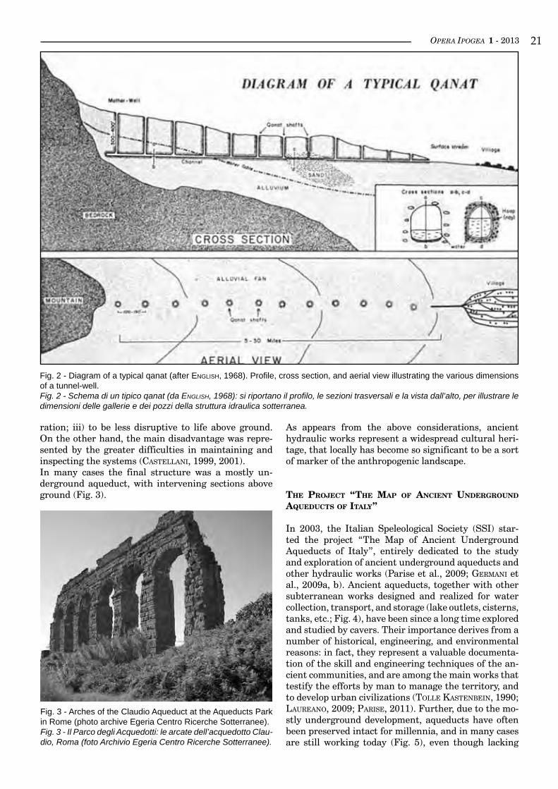
Water has always been fundamental for the birth and development of ancient civilizations, and its availabili-ty has played a crucial role in the choice of the sites for new settlements in many periods of the human history. When the hydric resources were not present near-by, they were searched for, and hydraulic engineering works realized, in order to collect and transport them to the inhabited areas. This was generally obtained by means of aqueducts, developed underground (Fig. 1) for most of their length (Castellani & draGoni, 1990, 1997; Castellani, 1999, 2001).The oldest form of subterranean aqueducts engineered to collect groundwater is represented by qanats (Fig. 2): this term, which takes its root from a Semitic word
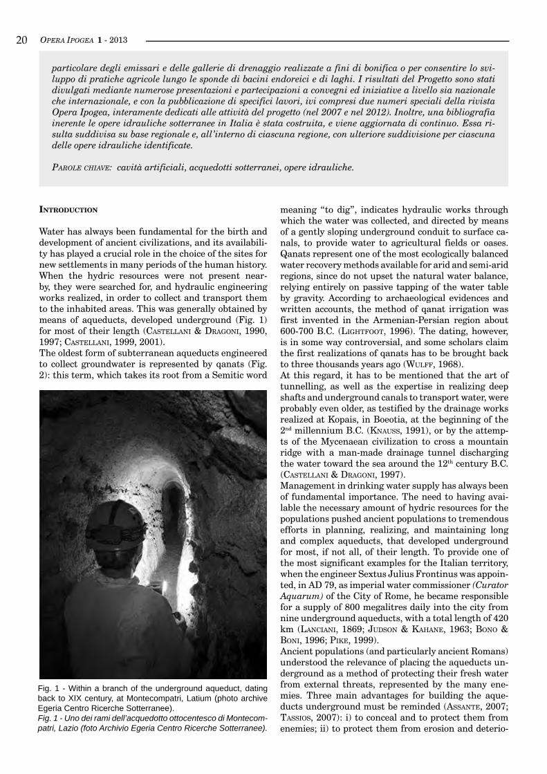
meaning “to dig”, indicates hydraulic works through which the water was collected, and directed by means of a gently sloping underground conduit to surface ca-nals, to provide water to agricultural fields or oases. Qanats represent one of the most ecologically balanced water recovery methods available for arid and semi-arid regions, since do not upset the natural water balance, relying entirely on passive tapping of the water table by gravity. According to archaeological evidences and written accounts, the method of qanat irrigation was first invented in the Armenian-Persian region about 600-700 B.C. (liGhtFoot, 1996). The dating, however, is in some way controversial, and some scholars claim the first realizations of qanats has to be brought back to three thousands years ago (WulFF, 1968).At this regard, it has to be mentioned that the art of tunnelling, as well as the expertise in realizing deep shafts and underground canals to transport water, were probably even older, as testified by the drainage works realized at Kopais, in Boeotia, at the beginning of the 2nd millennium B.C. (knauss, 1991), or by the attemp-ts of the Mycenaean civilization to cross a mountain ridge with a man-made drainage tunnel discharging the water toward the sea around the 12th century B.C. (Castellani & draGoni, 1997).Management in drinking water supply has always been of fundamental importance. The need to having avai-lable the necessary amount of hydric resources for the populations pushed ancient populations to tremendous efforts in planning, realizing, and maintaining long and complex aqueducts, that developed underground for most, if not all, of their length. To provide one of the most significant examples for the Italian territory, when the engineer Sextus Julius Frontinus was appoin-ted, in AD 79, as imperial water commissioner (Curator Aquarum) of the City of Rome, he became responsible for a supply of 800 megalitres daily into the city from nine underground aqueducts, with a total length of 420 km (lanCiani, 1869; Judson & kahane, 1963; bono & boni, 1996; Pike, 1999).Ancient populations (and particularly ancient Romans) understood the relevance of placing the aqueducts un-derground as a method of protecting their fresh water from external threats, represented by the many ene-mies. Three main advantages for building the aque-ducts underground must be reminded (assante, 2007; tassios, 2007): i) to conceal and to protect them from enemies; ii) to protect them from erosion and deterio-
particolare degli emissari e delle gallerie di drenaggio realizzate a fini di bonifica o per consentire lo svi-luppo di pratiche agricole lungo le sponde di bacini endoreici e di laghi. I risultati del Progetto sono stati divulgati mediante numerose presentazioni e partecipazioni a convegni ed iniziative a livello sia nazionale che internazionale, e con la pubblicazione di specifici lavori, ivi compresi due numeri speciali della rivista Opera Ipogea, interamente dedicati alle attività del progetto (nel 2007 e nel 2012). Inoltre, una bibliografia inerente le opere idrauliche sotterranee in Italia è stata costruita, e viene aggiornata di continuo. Essa ri-sulta suddivisa su base regionale e, all’interno di ciascuna regione, con ulteriore suddivisione per ciascuna delle opere idrauliche identificate.
Parole chiave: cavità artificiali, acquedotti sotterranei, opere idrauliche.
Fig. 1 - Within a branch of the underground aqueduct, dating back to XIX century, at Montecompatri, Latium (photo archive Egeria Centro Ricerche Sotterranee).Fig. 1 - Uno dei rami dell’acquedotto ottocentesco di Montecom-patri, Lazio (foto Archivio Egeria Centro Ricerche Sotterranee).
OPERA IPOGEA 1 - 2013 ��
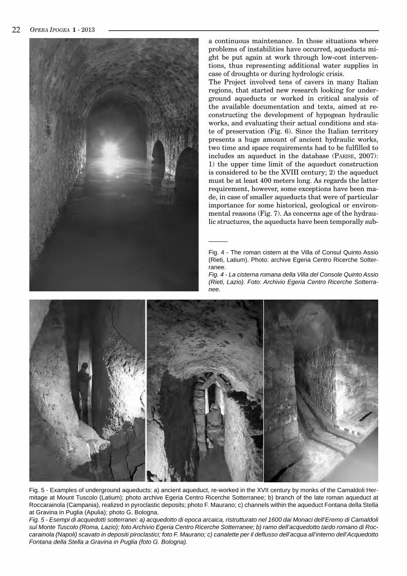
ration; iii) to be less disruptive to life above ground. On the other hand, the main disadvantage was repre-sented by the greater difficulties in maintaining and inspecting the systems (Castellani, 1999, 2001).In many cases the final structure was a mostly un-derground aqueduct, with intervening sections above ground (Fig. 3).
As appears from the above considerations, ancient hydraulic works represent a widespread cultural heri-tage, that locally has become so significant to be a sort of marker of the anthropogenic landscape.
THe ProjecT “THe maP of ancienT underGround aqueducTs of iTaly”
In 2003, the Italian Speleological Society (SSI) star-ted the project “The Map of Ancient Underground Aqueducts of Italy”, entirely dedicated to the study and exploration of ancient underground aqueducts and other hydraulic works (Parise et al., 2009; GerMani et al., 2009a, b). Ancient aqueducts, together with other subterranean works designed and realized for water collection, transport, and storage (lake outlets, cisterns, tanks, etc.; Fig. 4), have been since a long time explored and studied by cavers. Their importance derives from a number of historical, engineering, and environmental reasons: in fact, they represent a valuable documenta-tion of the skill and engineering techniques of the an-cient communities, and are among the main works that testify the efforts by man to manage the territory, and to develop urban civilizations (tolle kastenbein, 1990; laureano, 2009; Parise, 2011). Further, due to the mo-stly underground development, aqueducts have often been preserved intact for millennia, and in many cases are still working today (Fig. 5), even though lacking
Fig. 2 - Diagram of a typical qanat (after English, 1968). Profile, cross section, and aerial view illustrating the various dimensions of a tunnel-well.Fig. 2 - Schema di un tipico qanat (da English, 1968): si riportano il profilo, le sezioni trasversali e la vista dall’alto, per illustrare le dimensioni delle gallerie e dei pozzi della struttura idraulica sotterranea.
Fig. 3 - Arches of the Claudio Aqueduct at the Aqueducts Park in Rome (photo archive Egeria Centro Ricerche Sotterranee).Fig. 3 - Il Parco degli Acquedotti: le arcate dell’acquedotto Clau-dio, Roma (foto Archivio Egeria Centro Ricerche Sotterranee).
OPERA IPOGEA 1 - 2013��a continuous maintenance. In those situations where problems of instabilities have occurred, aqueducts mi-ght be put again at work through low-cost interven-tions, thus representing additional water supplies in case of droughts or during hydrologic crisis.The Project involved tens of cavers in many Italian regions, that started new research looking for under-ground aqueducts or worked in critical analysis of the available documentation and texts, aimed at re-constructing the development of hypogean hydraulic works, and evaluating their actual conditions and sta-te of preservation (Fig. 6). Since the Italian territory presents a huge amount of ancient hydraulic works, two time and space requirements had to be fulfilled to includes an aqueduct in the database (Parise, 2007): 1) the upper time limit of the aqueduct construction is considered to be the XVIII century; 2) the aqueduct must be at least 400 meters long. As regards the latter requirement, however, some exceptions have been ma-de, in case of smaller aqueducts that were of particular importance for some historical, geological or environ-mental reasons (Fig. 7). As concerns age of the hydrau-lic structures, the aqueducts have been temporally sub-
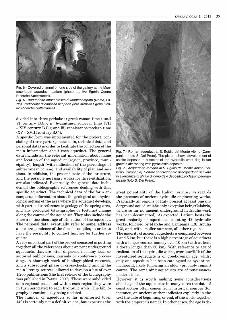
Fig. 4 - The roman cistern at the Villa of Consul Quinto Assio (Rieti, Latium). Photo: archive Egeria Centro Ricerche Sotter-ranee.Fig. 4 - La cisterna romana della Villa del Console Quinto Assio (Rieti, Lazio). Foto: Archivio Egeria Centro Ricerche Sotterra-nee.
Fig. 5 - Examples of underground aqueducts: a) ancient aqueduct, re-worked in the XVII century by monks of the Camaldoli Her-mitage at Mount Tuscolo (Latium); photo archive Egeria Centro Ricerche Sotterranee; b) branch of the late roman aqueduct at Roccarainola (Campania), realized in pyroclastic deposits; photo F. Maurano; c) channels within the aqueduct Fontana della Stella at Gravina in Puglia (Apulia); photo G. Bologna.Fig. 5 - Esempi di acquedotti sotterranei: a) acquedotto di epoca arcaica, ristrutturato nel 1600 dai Monaci dell’Eremo di Camaldoli sul Monte Tuscolo (Roma, Lazio); foto Archivio Egeria Centro Ricerche Sotterranee; b) ramo dell’acquedotto tardo romano di Roc-carainola (Napoli) scavato in depositi piroclastici; foto F. Maurano; c) canalette per il deflusso dell’acqua all’interno dell’Acquedotto Fontana della Stella a Gravina in Puglia (foto G. Bologna).
OPERA IPOGEA 1 - 2013 ��
divided into three periods: i) greek-roman time (until VI century B.C.); ii) byzantine-medioeval time (VII – XIV century B.C.); and iii) renaissance-modern time (XV – XVIII century B.C.).A specific form was implemented for the project, con-sisting of three parts (general data, technical data, and personal data) in order to facilitate the collection of the main information about each aqueduct. The general data include all the relevant information about name and location of the aqueduct (region, province, muni-cipality), length (with indication of the percentage of subterranean course), and availability of plan and sec-tions. In addition, the present state of the structure, and the possible necessary works for its re-utilization, are also indicated. Eventually, the general data inclu-des all the bibliographic references dealing with that specific aqueduct. The technical data of the form en-compasses information about the geological and hydro-logical setting of the area where the aqueduct develops, with particular reference to geology of the spring area, and any geological (stratigraphic or tectonic) change along the course of the aqueduct. They also include the known notice about age of utilization of the aqueduct. The personal data, eventually, refer to name, address and correspondence of the form’s compiler, in order to have the possibility to contact him/her for further re-quests.A very important part of the project consisted in putting together all the references about ancient underground aqueducts, that are often dispersed in many local or sectorial publications, journals or conference procee-dings. A thorough work of bibliographical research, and a subsequent phase of cross-checking among the main literary sources, allowed to develop a list of over 1,200 publications (the first release of the bibliography was published in Parise, 2007). These were subdivided on a regional basis, and within each region they were in turn associated to each hydraulic work. The biblio-graphy is continuously being updated.The number of aqueducts so far inventoried (over 140) is certainly not a definitive one, but expresses the
great potentiality of the Italian territory as regards the presence of ancient hydraulic engineering works. Practically all regions of Italy present at least one un-derground aqueduct (the only exception being Calabria, where so far no ancient underground hydraulic work has been documented). As expected, Latium hosts the great majority of aqueducts, counting 42 hydraulic works, followed by Marche and Campania (13), Apulia (12), and, with smaller numbers, all other regions.The majority of ancient aqueducts is comprised between 1 and 5 km, but there is a high percentage of aqueducts with a longer course, namely over 10 km (with at least a dozen longer than 30 km). With reference to age of realization of the hydraulic works, over four/fifth of the inventoried aqueducts is of greek-roman age, whilst only one aqueduct has been catalogued as byzantine-medioeval, likely following an older (probably roman) course. The remaining aqueducts are of renaissance-modern time.However, it is worth making some considerations about age of the aqueducts: in many cases the date of construction often comes from historical sources (for instance, an ancient author indicates explicitly in the text the date of beginning, or end, of the work, together with the emperor’s name). In other cases, the age is de-
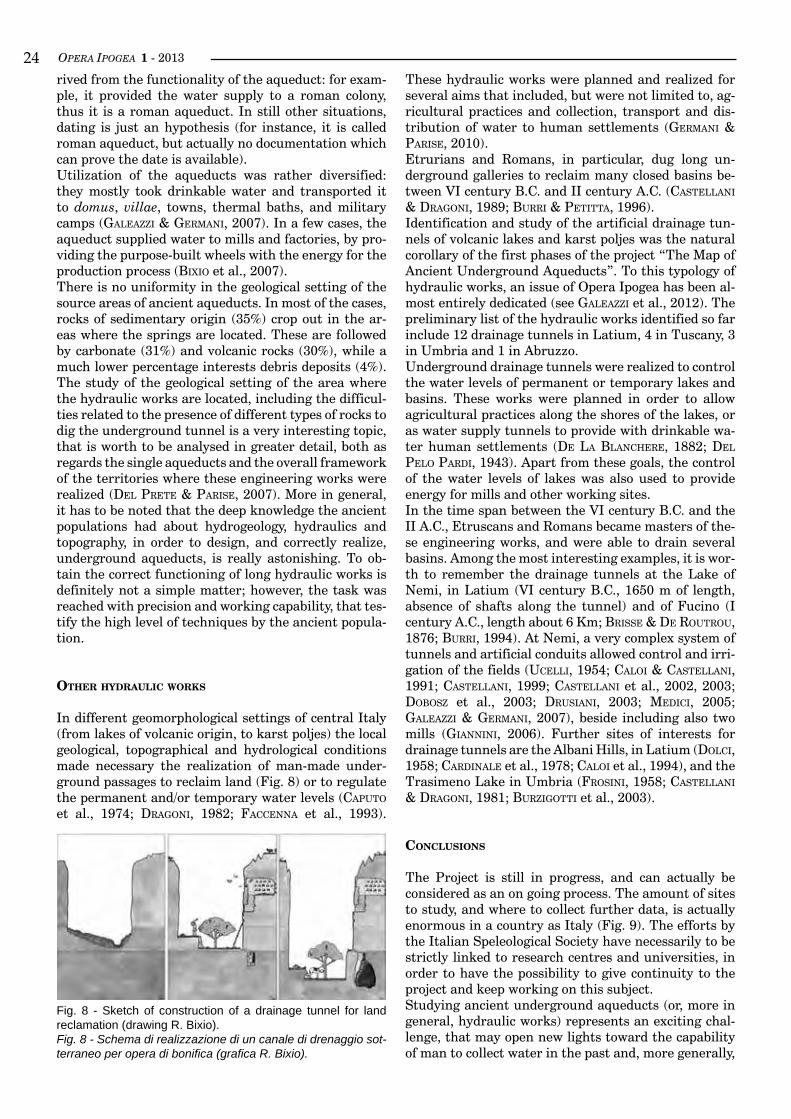
Fig. 6 - Covered channel on one side of the gallery at the Mon-tecompatri aqueduct, Latium (photo archive Egeria Centro Ricerche Sotterranee).Fig. 6 - Acquedotto ottocentesco di Montecompatri (Roma, La-zio). Particolare di canalina ricoperta (foto Archivio Egeria Cen-tro Ricerche Sotterranee).
Fig. 7 - Roman aqueduct at S. Egidio del Monte Albino (Cam-pania; photo S. Del Prete). The picture shows development of calcite deposits in a sector of the hydraulic work dug in fan gravels alternating with pyroclastic deposits.Fig. 7 - Acquedotto romano di S. Egidio del Monte Albino (Sa-lerno, Campania). Settore concrezionato di acquedotto scavato in alternanze di ghiaie di conoide e depositi piroclastici pedoge-nizzati (foto S. Del Prete).
OPERA IPOGEA 1 - 2013��rived from the functionality of the aqueduct: for exam-ple, it provided the water supply to a roman colony, thus it is a roman aqueduct. In still other situations, dating is just an hypothesis (for instance, it is called roman aqueduct, but actually no documentation which can prove the date is available).Utilization of the aqueducts was rather diversified: they mostly took drinkable water and transported it to domus, villae, towns, thermal baths, and military camps (Galeazzi & GerMani, 2007). In a few cases, the aqueduct supplied water to mills and factories, by pro-viding the purpose-built wheels with the energy for the production process (bixio et al., 2007).There is no uniformity in the geological setting of the source areas of ancient aqueducts. In most of the cases, rocks of sedimentary origin (35%) crop out in the ar-eas where the springs are located. These are followed by carbonate (31%) and volcanic rocks (30%), while a much lower percentage interests debris deposits (4%). The study of the geological setting of the area where the hydraulic works are located, including the difficul-ties related to the presence of different types of rocks to dig the underground tunnel is a very interesting topic, that is worth to be analysed in greater detail, both as regards the single aqueducts and the overall framework of the territories where these engineering works were realized (del Prete & Parise, 2007). More in general, it has to be noted that the deep knowledge the ancient populations had about hydrogeology, hydraulics and topography, in order to design, and correctly realize, underground aqueducts, is really astonishing. To ob-tain the correct functioning of long hydraulic works is definitely not a simple matter; however, the task was reached with precision and working capability, that tes-tify the high level of techniques by the ancient popula-tion.
oTHer Hydraulic Works
In different geomorphological settings of central Italy (from lakes of volcanic origin, to karst poljes) the local geological, topographical and hydrological conditions made necessary the realization of man-made under-ground passages to reclaim land (Fig. 8) or to regulate the permanent and/or temporary water levels (CaPuto et al., 1974; draGoni, 1982; FaCCenna et al., 1993).
These hydraulic works were planned and realized for several aims that included, but were not limited to, ag-ricultural practices and collection, transport and dis-tribution of water to human settlements (GerMani & Parise, 2010).Etrurians and Romans, in particular, dug long un-derground galleries to reclaim many closed basins be-tween VI century B.C. and II century A.C. (Castellani & draGoni, 1989; burri & Petitta, 1996).Identification and study of the artificial drainage tun-nels of volcanic lakes and karst poljes was the natural corollary of the first phases of the project “The Map of Ancient Underground Aqueducts”. To this typology of hydraulic works, an issue of Opera Ipogea has been al-most entirely dedicated (see Galeazzi et al., 2012). The preliminary list of the hydraulic works identified so far include 12 drainage tunnels in Latium, 4 in Tuscany, 3 in Umbria and 1 in Abruzzo.Underground drainage tunnels were realized to control the water levels of permanent or temporary lakes and basins. These works were planned in order to allow agricultural practices along the shores of the lakes, or as water supply tunnels to provide with drinkable wa-ter human settlements (de la blanChere, 1882; del Pelo Pardi, 1943). Apart from these goals, the control of the water levels of lakes was also used to provide energy for mills and other working sites.In the time span between the VI century B.C. and the II A.C., Etruscans and Romans became masters of the-se engineering works, and were able to drain several basins. Among the most interesting examples, it is wor-th to remember the drainage tunnels at the Lake of Nemi, in Latium (VI century B.C., 1650 m of length, absence of shafts along the tunnel) and of Fucino (I century A.C., length about 6 Km; brisse & de routrou, 1876; burri, 1994). At Nemi, a very complex system of tunnels and artificial conduits allowed control and irri-gation of the fields (uCelli, 1954; Caloi & Castellani, 1991; Castellani, 1999; Castellani et al., 2002, 2003; dobosz et al., 2003; drusiani, 2003; MediCi, 2005; Galeazzi & GerMani, 2007), beside including also two mills (Giannini, 2006). Further sites of interests for drainage tunnels are the Albani Hills, in Latium (dolCi, 1958; Cardinale et al., 1978; Caloi et al., 1994), and the Trasimeno Lake in Umbria (Frosini, 1958; Castellani & draGoni, 1981; burziGotti et al., 2003).
conclusions
The Project is still in progress, and can actually be considered as an on going process. The amount of sites to study, and where to collect further data, is actually enormous in a country as Italy (Fig. 9). The efforts by the Italian Speleological Society have necessarily to be strictly linked to research centres and universities, in order to have the possibility to give continuity to the project and keep working on this subject.Studying ancient underground aqueducts (or, more in general, hydraulic works) represents an exciting chal-lenge, that may open new lights toward the capability of man to collect water in the past and, more generally,
Fig. 8 - Sketch of construction of a drainage tunnel for land reclamation (drawing R. Bixio).Fig. 8 - Schema di realizzazione di un canale di drenaggio sot-terraneo per opera di bonifica (grafica R. Bixio).
OPERA IPOGEA 1 - 2013 ��to work toward a sustainable use of the natural resour-ces (laureano, 1995; burri, 2002; Parise, 2011). On the other hand, the periodic hydrologic crises we experien-ce, often related to over-exploitation and degradation of the water resources, demonstrate that several lessons may be learned from the analysis of ancient hydrau-lic works (Castellani & draGoni, 1991; Parise et al., 2012).Aimed at further co-operations with foreign scholars and cavers, a systematic research about bibliographic references to ancient underground aqueducts outside of Italy was also started, and the first contributions in this sense published (Parise, 2012).The interest on the topic is in fact great even outsi-de the Italian boundaries, and especially in the other countries of the Mediterranean Basin, where many other important ancient hydraulic engineering works have been built and used during the different epochs. At the time we write (December 2012) a list of some hundreds of bibliographical references about under-ground aqueducts distributed all over the world has been compiled.
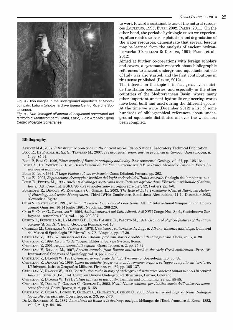
Fig. 9 - Two images in the underground aqueducts at Monte-compatri, Latium (photos: archive Egeria Centro Ricerche Sot-terranee).Fig. 9 - Due immagini all’interno di acquedotti sotterranei nel territorio di Montecompatri (Roma, Lazio). Foto Archivio Egeria Centro Ricerche Sotterranee.
bibliography
assante M.J., 2007, Infrastructure protection in the ancient world. Idaho National Laboratory Technical Publication.bixio r., de PasCale a., saJ s., traverso M., 2007, Tre acquedotti sotterranei in provincia di Genova. Opera Ipogea, n.
1, pp. 85-94.bono P., boni C., 1996, Water supply of Rome in antiquity and today. Environmental Geology, vol. 27, pp. 126-134.brisse a., de routrou L., 1876, Desséchement du lac Fucino exécuté par S.E. le Prince Alexandre Torlonia. Précis hi-
storique et technique.burri E. (ed.), 1994, Il Lago Fucino e il suo emissario. Carsa Edizioni, Pescara, pp. 262.burri E., 2002, Regimazione, drenaggio e bonifica dei laghi endoreici dell’Italia centrale. Geologia dell’ambiente, n. 4.burri e., Petitta M., 1996, Ancients drainages souterains pour l’activite agricole dans l’Etrurie meridionale (Latium,
Italie). Atti Conv. Int. ESRA ‘96 «L’eau souterraine en region agricole”, S2, Poitiers, pp. 5-8.burziGotti r., draGoni W., evanGelisti C., Gervasi L., 2003, The Role of Lake Trasimeno (Central Italy). In: History
of Hidrology and water Management. Third IWHA Conference, Bibliotheca Alexandrina, 11-14 December 2003, Alexandria, Egitto.
Caloi v., Castellani V., 1991, Notes on the ancient emissary of Lake Nemi. Atti 3rd International Symposium on Under-ground Quarries, 10-14 luglio 1991, Napoli, pp. 206-220.
Caloi v., CaPPa G., Castellani V., 1994, Antichi emissari nei Colli Albani. Atti XVII Congr. Naz. Spel., Castelnuovo Gar-fagnana, settembre 1994, vol. 1, pp. 299-307.
CaPuto C., FuniCiello r., la ManiCa G.b., luPia PalMieri e., Parotto M., 1974, Geomorphological features of the latian volcano (Alban Hill, Italy). Geologica Romana, vol. 13.
Cardinale M., Castellani v., viGnati A., 1978, L’emissario sotterraneo del Lago di Albano, duemila anni dopo. Quaderni del Museo di Speleologia “V. Rivera”, n. 7/8, L’Aquila, pp. 17-30.
Castellani V., 1996, Gli emissari dei Colli Albani: problemi storici e problemi di salvaguardia. Cocis, vol. V, n. 20.Castellani V., 1999, La civiltà dell’acqua. Editorial Service System, Roma.Castellani V., 2001, Acqua, acquedotti e qanat. Opera Ipogea, n. 2, pp. 25-32.Castellani v., draGoni M., 1997, Ancient tunnels: from Roman outlets back to the early Greek civilization. Proc. 12th
International Congress of Speleology, vol. 3, pp. 265-268.Castellani v., draGoni W., 1981, L’emissario medievale del lago Trasimeno. Speleologia, n.6, pp. 38.Castellani v., draGoni W., 1989, Opere idrauliche ipogee nel mondo romano: origine, sviluppo e impatto sul territorio.
L’Universo, Istituto Geografico Militare, Firenze, vol. 69, pp. 105-137.Castellani v., draGoni W., 1990, Contribution to the history of underground structures: ancient roman tunnels in central
Italy. In: sinha S. (Ed.), Int. Symp. on Unique Underground Structures, Denver, Colorado.Castellani v., draGoni W., 1991, Italian tunnels in antiquity. Tunnels and Tunnelling, 23, pp. 55-58.Castellani v., dobosz t., Galeazzi C., GerMani C., 2002, Nemi. Nuove evidenze per l’antica storia dell’emissario nemo-
rense (Roma). Opera Ipogea, n. 2, pp. 51-58.Castellani v., Caloi v., dobosz t., Galeazzi C., Galeazzi s., GerMani C., 2003, L’emissario del Lago di Nemi. Indagine
topografico-strutturale. Opera Ipogea, n. 2/3, pp. 2-76.de la blanChere M.R., 1882, La malaria de Rome et le drainage antique. Mélanges de l’Ecole francaise de Rome, 1882,
vol. 2, n. 1, p. 94-106.
OPERA IPOGEA 1 - 2013��
del Pelo Pardi G., 1943, Bonifiche antichissime. La malaria e i cunicoli del Lazio. Atti Reale Accademia dei Georgofili, Firenze, pp. 1-37.
del Prete s., Parise M., 2007, L’influenza dei fattori geologici e geomorfologici sulla realizzazione di cavità artificiali. Opera Ipogea, n. 2, pp. 3-16.
dobosz t., FiliPPi G., Galeazzi C., Galeazzi s., GerMani C., 2003, Gli ipogei aricini, nemorensi e del lago di Albano. Opera Ipogea, n. 2/3, pp. 77-144.
dolCi M., 1958, Esplorazioni dell’emissario del Lago di Albano in comune di Castel Gandolfo. Notiziario del Circolo Speleologico Romano, anno VIII, pp. 17-19.
draGoni W., 1982, Idrogeologia del lago Trasimeno: sintesi, problemi, aggiornamenti. Geografia Fisica e Dinamica Quaternaria, vol. 5.
drusiani R., 2003, L’antico emissario del lago di Nemi. Considerazioni sulla regolazione idraulica. L’Acqua, n. 4.enGlish P.W., 1968, The origin and spread of qanats in the Old World. Proceedings of the American Philosophical So-
ciety, vol. 112, n. 3, pp. 170-181.FaCCenna C., Florindo F., FuniCiello r., loMbardi S., 1993, Tectonic setting and sinkhole features: case histories from
western central Italy. Quaternary Proocedings, 3, pp. 47-56.Frosini P., 1958, Il lago Trasimeno e il suo antico emissario. Bollettino della Società Geografica Italiana, 11.Galeazzi C., GerMani C., 2007, Acquedotto antico: configurazione strutturale dell’opera idraulica. Opera Ipogea, n. 1,
pp. 69-74.Galeazzi C., GerMani C., Parise M., 2012, Gli antichi emissari artificiali dei bacini endoreici. Opera Ipogea, n. 1, pp.
3-10.GerMani C., Galeazzi C., Parise M., saMMarCo M., 2009a, Gli antichi acquedotti sotterranei: esempi di uso sostenibile del-
le risorse idriche. Proc. Congr. “La crisi dei sistemi idrici: approvvigionamento agro-industriale e civile”, Accademia dei Lincei, Roma, 22 March 2007, Atti Convegni Lincei, vol. 248, pp. 217-223.
GerMani C., Galeazzi C., Parise M., saMMarCo M., 2009b, La carta degli antichi acquedotti sotterranei: stato dell’arte e prospettive future. Proc. Congr. “Acque interne in Italia: uomo e natura”, Accademia dei Lincei, Roma, 28 March 2008, Atti Convegni Lincei, vol. 250, p. 335-340.
GerMani C., Parise M., 2010, Interventi antropici nel bacino idrografico del Fiume Tevere: gli antichi emissari sotterra-nei. Atti Convegno “Il bacino del Tevere”, Accademia dei Lincei, Roma, 23 marzo 2009, Atti Convegni Lincei, vol. 254, pp. 189-195.
Judson s., kahane A., 1963, Underground drainageways in southern Europa and northern Lazio. Pap. British Sch. Rome, 31, pp. 74-99.
knauss J., 1991, Arkadian and Boiotian Orchomenos, centre of mycenaean hydraulic engineering. Proc. 2nd Int. Congr. Micenologia.
lanCiani R., 1879, Di alcune opere di risanamento nell’Agro Romano eseguite dagli antichi. Atti Accademia dei Lincei, s. II, vol. 2.
laureano P., 1995, La piramide rovesciata. Bollati Boringhieri.laureano P., 2009, Ancient water management techniques to contrast drought and desertification in the Mediterranean.
Proc. IWA 2nd Int. Symp. “Water and Wastewater Technologies in Ancient Civilizations”, May 28-30, 2009, BariliGhtFoot D.R., 1996, Syrian qanat Romani: history, ecology, abandonment. Journal of Arid Environments, vol. 33, pp.
321-336.MediCi F., 2005, Laghi Albano e di Nemi: carenza idrica e alterazione della qualità delle acque, Geologia dell’Ambiente,
SIGEA, anno XIII, n. 1, pp. 8-11.Parise M., 2007, Il Progetto “La Carta degli Antichi Acquedotti Italiani”. Opera Ipogea, n. 1, pp. 3-16.Parise M., 2011, Managing water resources in the karst of southern Italy: an historical survey. Proceedings H2Karst, 9th
Conference on Limestone Hydrogology, Besançon (France), 1-3 september 2011, pp. 383-386.Parise M., 2012, Underground aqueducts: a first preliminary bibliography around the world. Proceedings 3rd IWA Spe-
cialized Conference on “Water and Wastewater Technologies in Ancient Civilizations”, Istanbul, 22-24 March 2012, pp. 65-72.
Parise M., MaranGella a., Maranò P., saMMarCo M., sanniCola G., 2012, Ancient hydraulic systems for collection, tran-sport and storage of water in karst settings of southern Italy. Proceedings 3rd IWA Specialized Conference on “Water and Wastewater Technologies in Ancient Civilizations”, Istanbul, 22-24 March 2012, pp. 73-80.
Parise M., bixio r., burri e., Caloi v., del Prete s., Galeazzi C., GerMani C., GuGlia P., MeneGhini M., saMMarCo M., 2009, The map of ancient underground aqueducts: a nation-wide project by the Italian Speleological Society. Proc 15th Int. Congress of Speleology, Kerrville (Texas, USA), 19-26 July 2009, vol. 3, pp. 2027-2032.
Pike E.B., 1999, Drinking water supply - a backward look into the future. The Environmentalist, vol. 19, pp. 5-9.Tassios T.P., 2007, Water supply of ancient Greek cities. Water Science & Technology: Water Supply, vol. 7 (1), pp. 165-
172.tölle kastenbein R., 1990, Archeologia dell’acqua. Longanesi & C., Milano.uCelli G., 1954, L’Emissario del Lago di Nemi. In: Le meraviglie del passato. Mondadori, pp. 391-398.WulFF H.E., 1968, The aqueducts of Iran. Scientific American, pp. 94-105.
OPERA IPOGEA 1 - 2013 ��
A Mediterranean Troglodytism database. An overview on the rupestrian settlemen-ts of the Mediterranean regionMario Mainetti
Abstract
The research on Mediterranean Troglodytism was started by architects Mario Mainetti and Erica Besana while studying hypogean architecture in 1999 and it was later developed in collaboration with the National Commission on Artificial Cavities of the Italian Speleological Society, together with Carla Galeazzi, Roberto Bixio, and Andrea De Pascale.Focused on cave-dwellers and based on a vast and growing bibliography, this study is a reliable tool for the National Register of Artificial Cavities and aims at analysing and describing this specific practice, signifi-cantly experimented all over the Mediterranean territories. The idea to build this directory originates from the will to provide a database of information for those who deal at any level with artificial cavities.The research on the Mediterranean troglodyte architecture is represented in 3 general maps and 23 regional cuts. This article is illustrated by a general map of the Mediterranean region showing images of some of the venues, as an overview of the whole research, and two maps focusing on Sardinia and Crete, associated with the corresponding lists of sites and bibliography.The functions recognized and taken into consideration in this study are as follows: ancient and contempo-rary troglodyte or semi-troglodyte dwellings, sacred sites, temporary shelters and defences, utilities (but not funerary architecture or water storage systems). The encoding of these classification is currently under re-view, in order to be aligned with the codes and typologies identified and defined by the National Commission on Artificial Cavities of the Italian Speleological Society.
key worDS: troglodytism, rupestrian settlements, Mediterranean Basin.
Riassunto
per un database deL trogLoditismo mediterraneo. un’indagine suLLa diffusione degLi insediamenti rupestri neLLa regione mediterranea
La ricerca sul trogloditismo mediterraneo è un’indagine iniziata nel 1999 da Mario Mainetti ed Erica Be-sana sulla diffusione delle architetture scavate dell’area mediterranea, e sviluppata negli anni seguenti con la collaborazione e poi nel seno delle attività della Commissione Nazionale Cavità Artificiale della Società Speleologica Italiana, tra gli altri con Carla Galeazzi, Roberto Bixio ed Andrea De Pascale. Lo studio, par-ticolarmente centrato sulla raccolta di dati sull’abitare in grotta e nato dalla consultazione di una vasta e crescente bibliografia, si pone in Italia come strumento complementare alla compilazione del Catasto Nazio-nale delle Cavità Artificiali, contribuendo a definire il più possibile, e nel modo più preciso, l’entità di un fe-nomeno che interessa buona parte del territorio mediterraneo e necessita di un censimento che sia strumento per una tutela diffusa sul territorio.Il progetto, in via di pubblicazione, è rappresentato in 3 carte generali e 23 di dettaglio. Questo articolo è illustrato da una carta alla scala del Mediterraneo con immagini di alcuni dei siti censiti, quale presenta-zione dell’intera ricerca, e da due mappe di approfondimento su Creta e la Sardegna, associate agli elenchi e alla bibliografia corrispondenti.Con lo scopo di non perdere informazioni utili a futuri approfondimenti, e cercando il più possibile di non perdere la visione d’insieme di uno studio il cui interesse è anche quello di riconoscere e confrontare quello che è stato già studiato in molte sue parti, si è preferito adattare alle realtà regionali la scala di classifica-zione e rappresentazione dei siti segnalati. Così, nelle mappe, siti censiti può corrispondere, a seconda dei casi, sia una singola cavità artificiale che un grande insieme, avente più funzioni, fino anche alla scala del villaggio o di una porzione estesa di territorio, quali ad esempio una valle o un’intera isola.Tuttavia rimane evidente la grande differenza nel numero di località individuate nelle diverse nazioni o regioni nelle quali il fenomeno è stato riconosciuto (si veda la tabella nel testo inglese). Essa dipende sia dal-
OPERA IPOGEA 1 - 2013��
The research on Mediterranean Troglodytism was started by architects Mario Mainetti and Erica Besana while studying hypogean architecture in 1999 and it was later developed in collaboration with the National Commission on Artificial Cavities of the Italian Speleological Society, together with Carla Galeazzi, Roberto Bixio, and Andrea De Pascale. Focused on cave-dwellers and based on a vast and growing bibliography, this study is a reliable tool for the National Register of Artificial Cavities and aims at analysing and describ-ing this specific practice, significantly experimented all over the Mediterranean territories.Nowadays the interest on underground architecture is growing for researchers as well as for the general audi-ence, although more sporadically. This is a consequence not only of the studies started in the Sixties, which con-sidered for the first time cave-dwelling as an architec-tural typology, but also of the new attention devoted to sustainable architecture. There are several examples of architectures which are now valued as cultural herit-age; nonetheless, an archipelago of minor centres, re-ligious sites, defence systems still remains hidden and barely known, and risks to be forgotten and lost.The idea to build this directory originates from the will to provide a database of information for those who deal at any level with artificial cavities. The map represent-ing the distribution of hypogean architectures in the Mediterranean area (Fig. 1) aims at being a guide for tourists, researchers and explorers: a link to connect all those people that, for professional reasons or for hobby, get involved into underground spaces.The research on the Mediterranean troglodyte architec-
ture is represented in 3 general maps and 23 regional plans. This article is illustrated by a general map of the Mediterranean region showing images of some of the venues (Fig. 1), as an overview of the whole research, and two maps focusing on Sardinia (Fig. 2) and Crete (Fig. 3), associated with the corresponding bibliogra-phy and lists of sites (Tabs. 1 and 2).The nations or regions where the phenomenon has been recognized are Albania, Algeria, western Armenia, Bosnia Herzegovina, Bulgaria, Cyprus, northern Egypt, southern France, western Georgia, Gibraltar, Jordan, Greece, Israel, Italy, Lebanon, Libya, Macedonia, Malta, Montenegro, Morocco, southern Moldavia, Palestine, Portugal, Romania, San Marino, Serbia (in-cluding Kosovo), Syria, Spain, Switzerland, Tunisia, Turkey and southern Ukraine (Tab. 3). Unfortunately the need to mark the geographical limits of this study has led to the inevitable exclusion of some areas with a strong troglodyte tradition, to be found in the immedi-ate proximity of the Mediterranean, but information on these areas was however collected, in view of an ex-tension of the research.In order to keep information that might be useful for future studies, and endeavouring as far as possible not to lose sight of the overall perspective in a publication that also aims to acknowledge and compare what has already been studied under many aspects, we have chosen to adapt the scale on which the sites quoted are represented and classified to the situations in in-dividual regions. The maps do, in fact, belong to two scales of detail, and the association of a code to each place may correspond, in individual cases, either to a
l’effettiva diffusione – legata alle caratteristiche geologiche dei territori, alla densità di popolazione e alle vi-cende storiche delle regioni che compongono le moderne entità statali – sia dall’estensione del loro territorio o dal settore preso in considerazione. Non ultimo, dalla diversa quantità o qualità di studi e pubblicazioni dedicate all’argomento, e dalla loro reperibilità e accessibilità alla consultazione.La missione di uniformare la diversità delle informazioni raccolte, e l’interpretazione insita nei diversi gra-di di classificazione, è assegnata agli elenchi di dettaglio, che permettono di associare ognuna delle quasi duemila località censite alla propria posizione nel territorio. In questi elenchi non solo a ogni sito è associato un codice alfanumerico utile alla localizzazione nella carta, al riconoscimento della nazione e alla indicazio-ne della relativa funzione, ma anche il nome della località, il nome della cavità stessa, se noto, la posizione nel territorio nel comune, contrada o frazione, ed eventuali altre informazioni utili al suo riconoscimento.Quindi l’elenco, seppure corrispondente alle 23 carte, resta aperto a ulteriori future o parziali rappresen-tazioni, così come allo studio comparato delle funzioni predominanti nelle diverse regioni mediterranee. Nella creazione dei codici, alla lettera assegnata alla relativa mappa segue, infatti, un codice numerico a tre cifre identificativo della località censita, l’indicazione della nazione, la segnalazione attraverso lettere delle funzioni presenti e un numero che rimanda alle fonti bibliografiche o orali nelle quali sono state descritte o citate le cavità interamente o parzialmente artificiali.Le funzioni riconosciute e prese in considerazione in questo studio sono: abitazioni trogloditiche e semitro-gloditiche antiche (A), o contemporanee (dall’inizio del XX sec., A*, con lo scopo di individuare la vitalità del fenomeno rupestre), luoghi di culto (chiese, eremi, monasteri, moschee, templi e santuari pagani, B), rifugi temporanei e sistemi difensivi (C), funzioni utilitarie (cantine, granai, laboratori, terme, ma non architetture funerarie o di captazione idrica, D). Nel codice può essere segnalata anche la mancanza d’informazioni circa la reale funzione della cavità, spesso non chiara nelle cavità storiche (E). Questi codici sono in via di revi-sione, con lo scopo di uniformarli a quelli identificati e definiti dalla Commissione Nazionale delle Cavità Artificiali della Società Speleologica Italiana.
Parole chiave: trogloditismo, insediamenti rupestri, Mediterraneo.
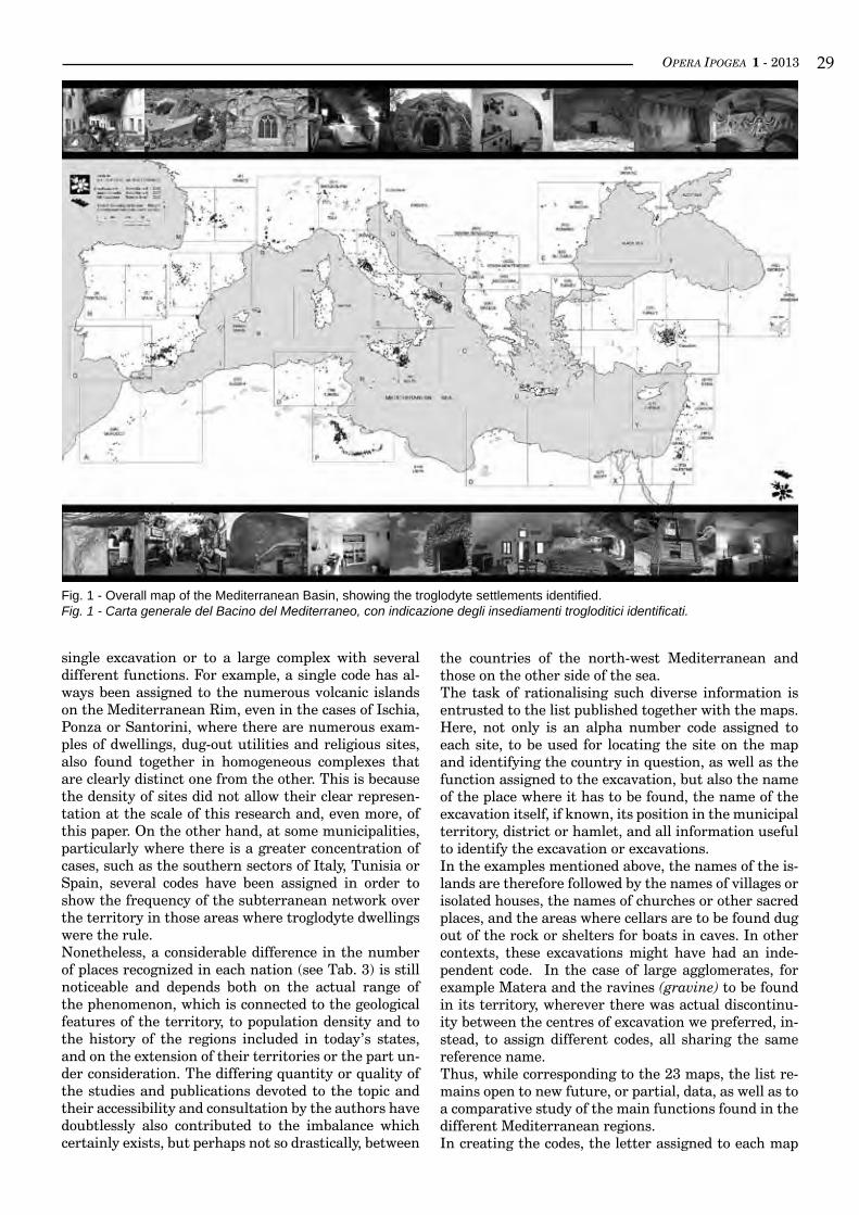
OPERA IPOGEA 1 - 2013 ��
Fig. 1 - Overall map of the Mediterranean Basin, showing the troglodyte settlements identified.Fig. 1 - Carta generale del Bacino del Mediterraneo, con indicazione degli insediamenti trogloditici identificati.
single excavation or to a large complex with several different functions. For example, a single code has al-ways been assigned to the numerous volcanic islands on the Mediterranean Rim, even in the cases of Ischia, Ponza or Santorini, where there are numerous exam-ples of dwellings, dug-out utilities and religious sites, also found together in homogeneous complexes that are clearly distinct one from the other. This is because the density of sites did not allow their clear represen-tation at the scale of this research and, even more, of this paper. On the other hand, at some municipalities, particularly where there is a greater concentration of cases, such as the southern sectors of Italy, Tunisia or Spain, several codes have been assigned in order to show the frequency of the subterranean network over the territory in those areas where troglodyte dwellings were the rule.Nonetheless, a considerable difference in the number of places recognized in each nation (see Tab. 3) is still noticeable and depends both on the actual range of the phenomenon, which is connected to the geological features of the territory, to population density and to the history of the regions included in today’s states, and on the extension of their territories or the part un-der consideration. The differing quantity or quality of the studies and publications devoted to the topic and their accessibility and consultation by the authors have doubtlessly also contributed to the imbalance which certainly exists, but perhaps not so drastically, between
the countries of the north-west Mediterranean and those on the other side of the sea.The task of rationalising such diverse information is entrusted to the list published together with the maps. Here, not only is an alpha number code assigned to each site, to be used for locating the site on the map and identifying the country in question, as well as the function assigned to the excavation, but also the name of the place where it has to be found, the name of the excavation itself, if known, its position in the municipal territory, district or hamlet, and all information useful to identify the excavation or excavations.In the examples mentioned above, the names of the is-lands are therefore followed by the names of villages or isolated houses, the names of churches or other sacred places, and the areas where cellars are to be found dug out of the rock or shelters for boats in caves. In other contexts, these excavations might have had an inde-pendent code. In the case of large agglomerates, for example Matera and the ravines (gravine) to be found in its territory, wherever there was actual discontinu-ity between the centres of excavation we preferred, in-stead, to assign different codes, all sharing the same reference name.Thus, while corresponding to the 23 maps, the list re-mains open to new future, or partial, data, as well as to a comparative study of the main functions found in the different Mediterranean regions.In creating the codes, the letter assigned to each map
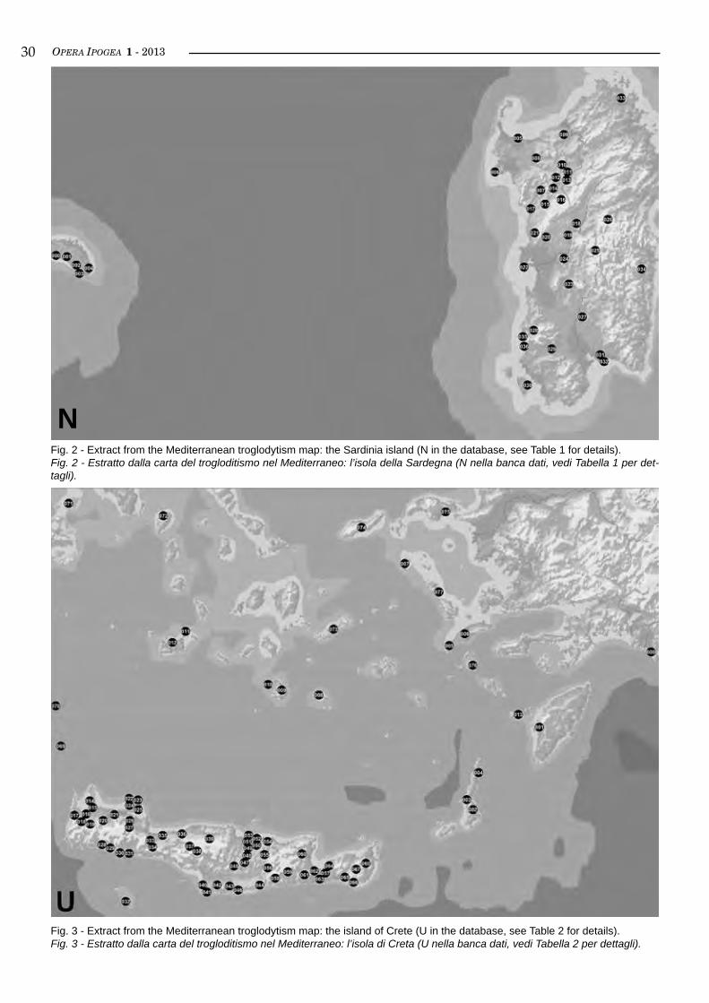
OPERA IPOGEA 1 - 2013�0
Fig. 2 - Extract from the Mediterranean troglodytism map: the Sardinia island (N in the database, see Table 1 for details).Fig. 2 - Estratto dalla carta del trogloditismo nel Mediterraneo: l’isola della Sardegna (N nella banca dati, vedi Tabella 1 per det-tagli).
Fig. 3 - Extract from the Mediterranean troglodytism map: the island of Crete (U in the database, see Table 2 for details).Fig. 3 - Estratto dalla carta del trogloditismo nel Mediterraneo: l’isola di Creta (U nella banca dati, vedi Tabella 2 per dettagli).
N
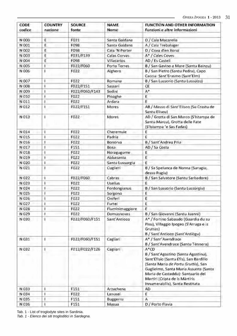
OPERA IPOGEA 1 - 2013 ��
Tab. 1 - List of troglodyte sites in Sardinia.Tab. 1 - Elenco dei siti trogloditici in Sardegna.
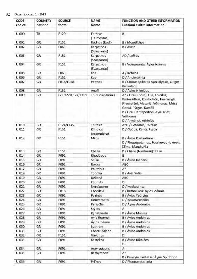
OPERA IPOGEA 1 - 2013��
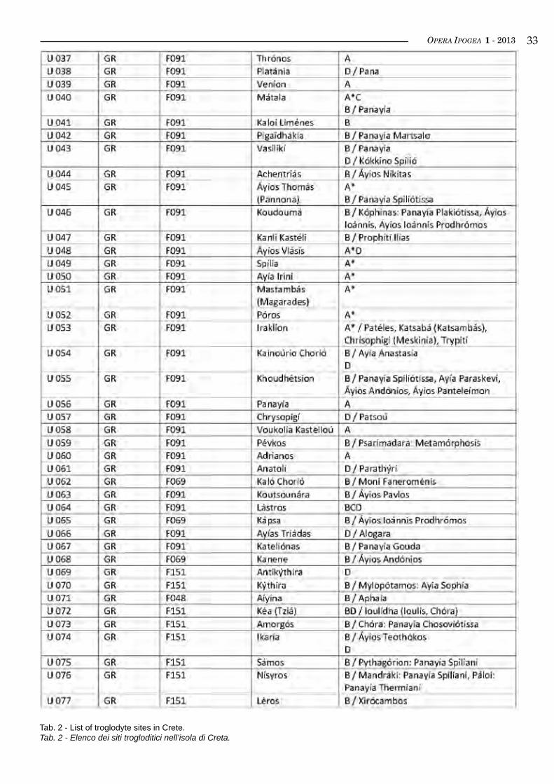
OPERA IPOGEA 1 - 2013 ��
Tab. 2 - List of troglodyte sites in Crete.Tab. 2 - Elenco dei siti trogloditici nell’isola di Creta.
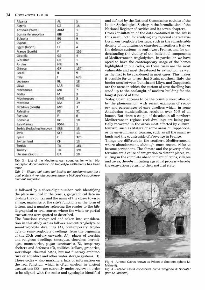
OPERA IPOGEA 1 - 2013��
is followed by a three-digit number code identifying the place included in the census, geographical data in-cluding the country and the name of the closer town or village, markings of the site’s functions in the form of letters, and a number referring the reader to the bib-liographical or oral sources where the whole or partial excavations were quoted or described.The functions recognized and taken into considera-tion in this study are as follows: ancient troglodyte or semi-troglodyte dwellings (A), contemporary troglo-dyte or semi-troglodyte dwellings (from the beginning of the 20th century onwards, A*), places of worship and religious dwellings (mosques, churches, hermit-ages, monasteries, pagan sanctuaries, B), temporary shelters and defences (C), utilities (cellars, granaries, workshops, thermal baths, but not funerary architec-ture or aqueduct and other water storage systems, D). These codes – also marking a lack of information on the real function, which is often unclear in ancient excavations (E) – are currently under review, in order to be aligned with the codes and typologies identified
Tab. 3 - List of the Mediterranean countries for which bib-liographic documentation on troglodyte settlements has been found.Tab. 3 - Elenco dei paesi del Bacino del Mediterraneao per I quali è stata rinvenuta documentazione bibliografica sugli inse-diamenti trogloditici.
and defined by the National Commission cavities of the Italian Speleological Society in the formalization of the National Register of cavities and its seven chapters.Cross consultation of the data contained in the list is thus useful both for studying any regional characteris-tics in our troglodyte heritage, such as the considerable density of mountainside churches in southern Italy or the defence systems in south-west France, and for un-derstanding the vitality of the individual components of Mediterranean troglodytism. In particular, we have opted to have the contemporary usage of the homes highlighted in our codes, as these cases are the most vulnerable and most threatened by extinction, as well as the first to be abandoned in most cases. This makes it possible for us to see that Spain, southern Italy, the border area between Tunisia and Libya, and Cappadocia are the areas in which the custom of cave-dwelling has stood up to the onslaught of modern building for the longest period of time.Today, Spain appears to be the country most affected by the phenomenon, with recent examples of recov-ery and percentages of cave dwellers which, in some Andalusian municipalities, result in over 50% of all homes. But since a couple of decades in all northern Mediterranean regions rock dwellings are being par-tially recovered in the areas most affected by cultural tourism, such as Matera or some areas of Cappadocia, or by environmental tourism, such as all the small is-lands and the countryside of Provence in France.Things are different in the southern Mediterranean, where abandonment, although more recent, risks to become permanent. The climate and the poverty of the terrains are a cause of emigration to distant places, re-sulting in the complete abandonment of crops, villages and caves, thereby initiating a gradual process whereby the excavations return to their natural state.
Fig. 4 - Athens: Caves known as Prison of Socrates (photo M. Mainetti).Fig. 4 - Atene: cavità conosciuta come “Prigione di Socrate” (foto M. Mainetti).
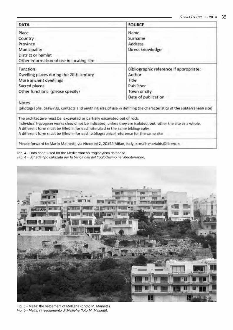
OPERA IPOGEA 1 - 2013 ��
Tab. 4 - Data sheet used for the Mediterranean troglodytism database. Tab. 4 - Scheda-tipo utilizzata per la banca dati del trogloditismo nel Mediterraneo.
Fig. 5 - Malta: the settlement of Mellieħa (photo M. Mainetti).Fig. 5 - Malta: l’insediamento di Mellieħa (foto M. Mainetti).
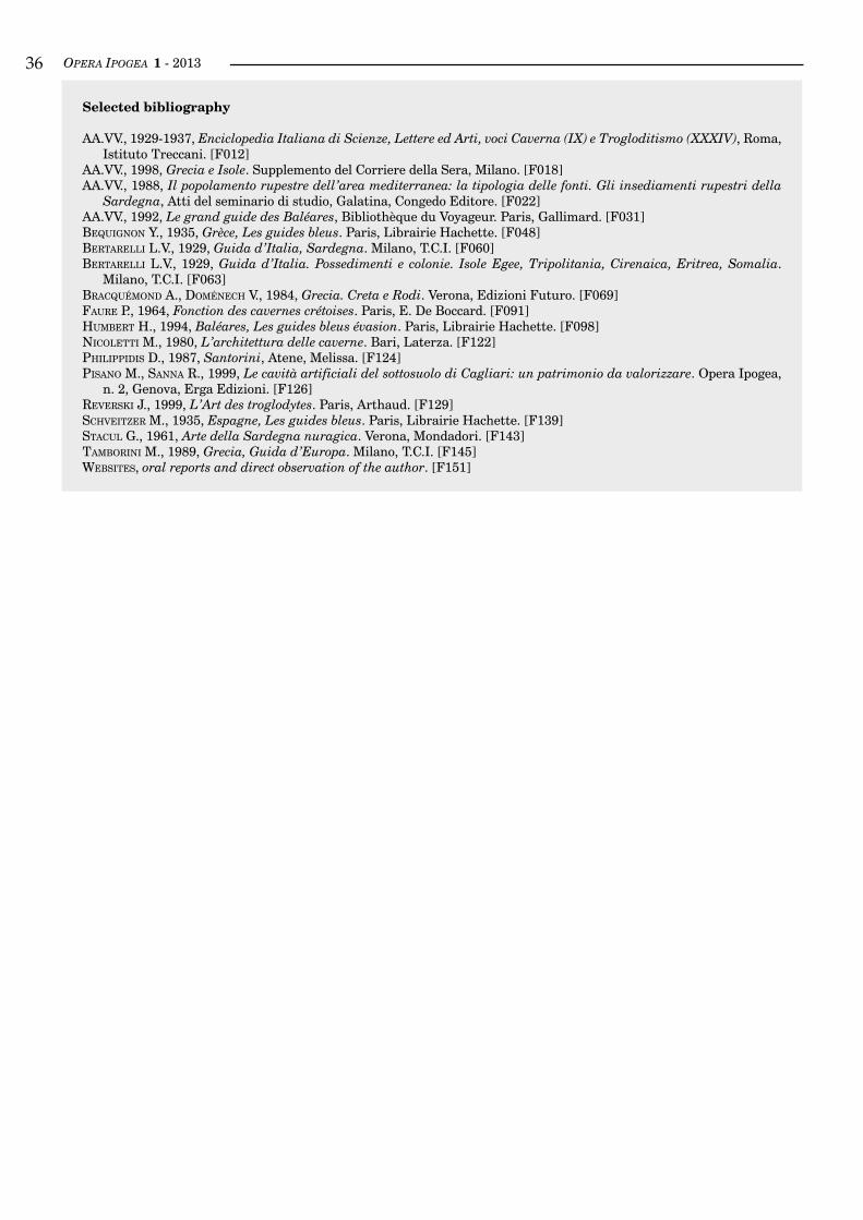
OPERA IPOGEA 1 - 2013��
selected bibliography
AA.VV., 1929-1937, Enciclopedia Italiana di Scienze, Lettere ed Arti, voci Caverna (IX) e Trogloditismo (XXXIV), Roma, Istituto Treccani. [F012]
AA.VV., 1998, Grecia e Isole. Supplemento del Corriere della Sera, Milano. [F018]AA.VV., 1988, Il popolamento rupestre dell’area mediterranea: la tipologia delle fonti. Gli insediamenti rupestri della
Sardegna, Atti del seminario di studio, Galatina, Congedo Editore. [F022]AA.VV., 1992, Le grand guide des Baléares, Bibliothèque du Voyageur. Paris, Gallimard. [F031]bequiGnon Y., 1935, Grèce, Les guides bleus. Paris, Librairie Hachette. [F048]bertarelli L.V., 1929, Guida d’Italia, Sardegna. Milano, T.C.I. [F060]bertarelli L.V., 1929, Guida d’Italia. Possedimenti e colonie. Isole Egee, Tripolitania, Cirenaica, Eritrea, Somalia.
Milano, T.C.I. [F063]braCquéMond A., doMéneCh V., 1984, Grecia. Creta e Rodi. Verona, Edizioni Futuro. [F069]Faure P., 1964, Fonction des cavernes crétoises. Paris, E. De Boccard. [F091]huMbert H., 1994, Baléares, Les guides bleus évasion. Paris, Librairie Hachette. [F098]niColetti M., 1980, L’architettura delle caverne. Bari, Laterza. [F122]PhiliPPidis D., 1987, Santorini, Atene, Melissa. [F124]Pisano M., sanna R., 1999, Le cavità artificiali del sottosuolo di Cagliari: un patrimonio da valorizzare. Opera Ipogea,
n. 2, Genova, Erga Edizioni. [F126]reverski J., 1999, L’Art des troglodytes. Paris, Arthaud. [F129]sChveitzer M., 1935, Espagne, Les guides bleus. Paris, Librairie Hachette. [F139]staCul G., 1961, Arte della Sardegna nuragica. Verona, Mondadori. [F143]taMborini M., 1989, Grecia, Guida d’Europa. Milano, T.C.I. [F145]Websites, oral reports and direct observation of the author. [F151]
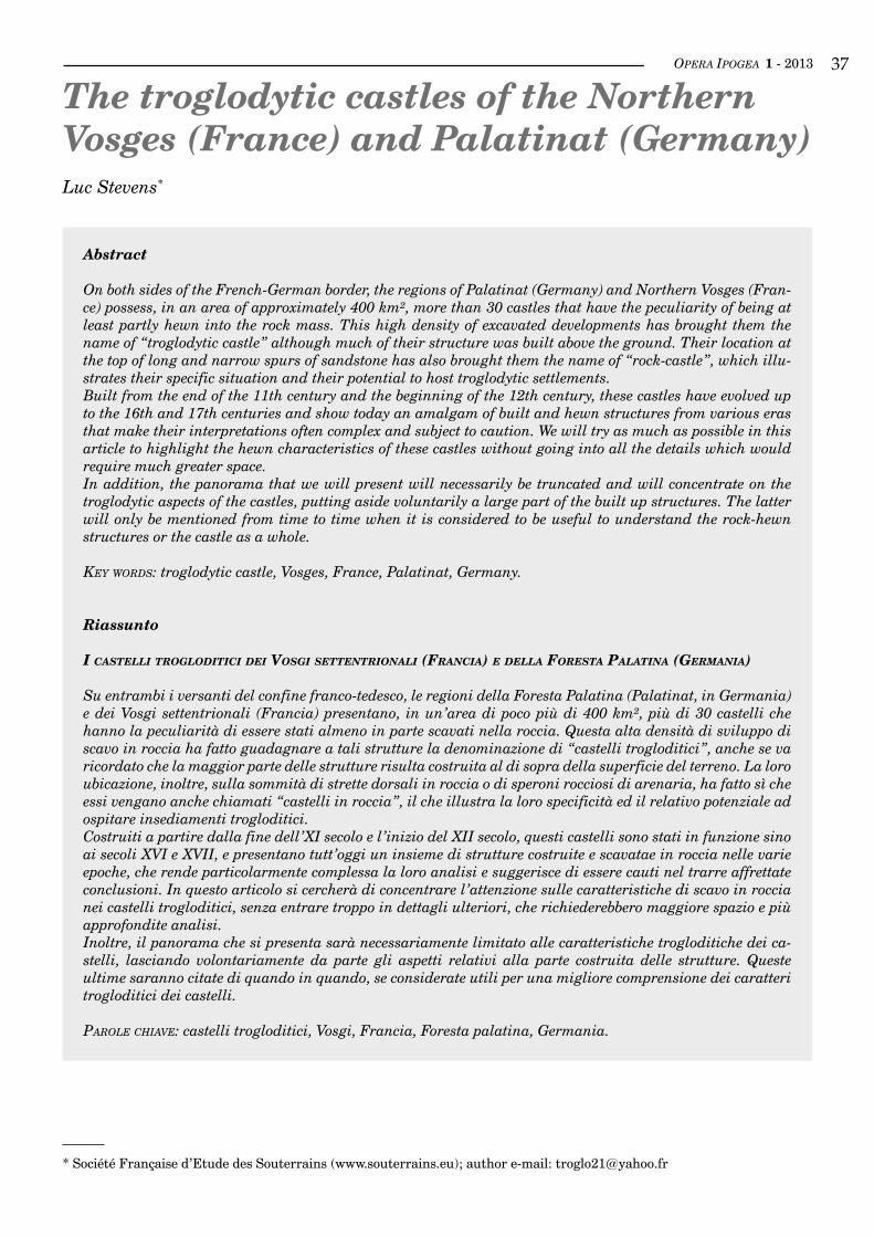
OPERA IPOGEA 1 - 2013 ��
The troglodytic castles of the NorthernVosges (France) and Palatinat (Germany)Luc Stevens*
Abstract
On both sides of the French-German border, the regions of Palatinat (Germany) and Northern Vosges (Fran-ce) possess, in an area of approximately 400 km², more than 30 castles that have the peculiarity of being at least partly hewn into the rock mass. This high density of excavated developments has brought them the name of “troglodytic castle” although much of their structure was built above the ground. Their location at the top of long and narrow spurs of sandstone has also brought them the name of “rock-castle”, which illu-strates their specific situation and their potential to host troglodytic settlements.Built from the end of the 11th century and the beginning of the 12th century, these castles have evolved up to the 16th and 17th centuries and show today an amalgam of built and hewn structures from various eras that make their interpretations often complex and subject to caution. We will try as much as possible in this article to highlight the hewn characteristics of these castles without going into all the details which would require much greater space.In addition, the panorama that we will present will necessarily be truncated and will concentrate on the troglodytic aspects of the castles, putting aside voluntarily a large part of the built up structures. The latter will only be mentioned from time to time when it is considered to be useful to understand the rock-hewn structures or the castle as a whole.
key worDS: troglodytic castle, Vosges, France, Palatinat, Germany.
Riassunto
i casteLLi trogLoditici dei vosgi settentrionaLi (francia) e deLLa foresta paLatina (germania)
Su entrambi i versanti del confine franco-tedesco, le regioni della Foresta Palatina (Palatinat, in Germania) e dei Vosgi settentrionali (Francia) presentano, in un’area di poco più di 400 km², più di 30 castelli che hanno la peculiarità di essere stati almeno in parte scavati nella roccia. Questa alta densità di sviluppo di scavo in roccia ha fatto guadagnare a tali strutture la denominazione di “castelli trogloditici”, anche se va ricordato che la maggior parte delle strutture risulta costruita al di sopra della superficie del terreno. La loro ubicazione, inoltre, sulla sommità di strette dorsali in roccia o di speroni rocciosi di arenaria, ha fatto sì che essi vengano anche chiamati “castelli in roccia”, il che illustra la loro specificità ed il relativo potenziale ad ospitare insediamenti trogloditici.Costruiti a partire dalla fine dell’XI secolo e l’inizio del XII secolo, questi castelli sono stati in funzione sino ai secoli XVI e XVII, e presentano tutt’oggi un insieme di strutture costruite e scavatae in roccia nelle varie epoche, che rende particolarmente complessa la loro analisi e suggerisce di essere cauti nel trarre affrettate conclusioni. In questo articolo si cercherà di concentrare l’attenzione sulle caratteristiche di scavo in roccia nei castelli trogloditici, senza entrare troppo in dettagli ulteriori, che richiederebbero maggiore spazio e più approfondite analisi.Inoltre, il panorama che si presenta sarà necessariamente limitato alle caratteristiche trogloditiche dei ca-stelli, lasciando volontariamente da parte gli aspetti relativi alla parte costruita delle strutture. Queste ultime saranno citate di quando in quando, se considerate utili per una migliore comprensione dei caratteri trogloditici dei castelli.
Parole chiave: castelli trogloditici, Vosgi, Francia, Foresta palatina, Germania.
* Société Française d’Etude des Souterrains (www.souterrains.eu); author e-mail: [email protected]
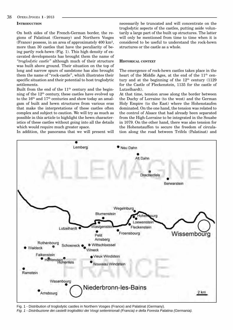
OPERA IPOGEA 1 - 2013��inTroducTion
On both sides of the French-German border, the re-gions of Palatinat (Germany) and Northern Vosges (France) possess, in an area of approximately 400 km², more than 30 castles that have the peculiarity of be-ing partly rock-hewn (Fig. 1). This high density of ex-cavated developments has brought them the name of “troglodytic castle” although much of their structure was built above ground. Their situation on the top of long and narrow spurs of sandstone has also brought them the name of “rock-castle”, which illustrates their specific situation and their potential to host troglodytic settlements.Built from the end of the 11th century and the begin-ning of the 12th century, these castles have evolved up to the 16th and 17th centuries and show today an amal-gam of built and hewn structures from various eras that make the interpretations of these castles often complex and subject to caution. We will try as much as possible in this article to highlight the hewn character-istics of these castles without going into all the details which would require much greater space.In addition, the panorama that we will present will
necessarily be truncated and will concentrate on the troglodytic aspects of the castles, putting aside volun-tarily a large part of the built up structures. The latter will only be mentioned from time to time when it is considered to be useful to understand the rock-hewn structures or the castle as a whole.
HisTorical conTexT
The emergence of rock-hewn castles takes place in the heart of the Middle Ages, at the end of the 11th cen-tury and at the beginning of the 12th century (1129 for the Castle of Fleckenstein, 1135 for the castle of Lutzelhardt).At that time, tension arose along the border between the Duchy of Lorraine (to the west) and the German Holy Empire (to the East) where the Hohenstaufen dominated. On the one hand, the tension was related to the control of Alsace that had already been separated from the High-Lorraine to be integrated in the Souabe in 1079. On the other hand, there was also tension for the Hohenstauffen to secure the freedom of circula-tion along the road between Trifels (Palatinat) and
Fig. 1 - Distribution of troglodytic castles in Northern Vosges (France) and Palatinat (Germany).Fig. 1 - Distribuzione dei castelli trogloditici dei Vosgi settentrionali (Francia) e della Foresta Palatina (Germania).
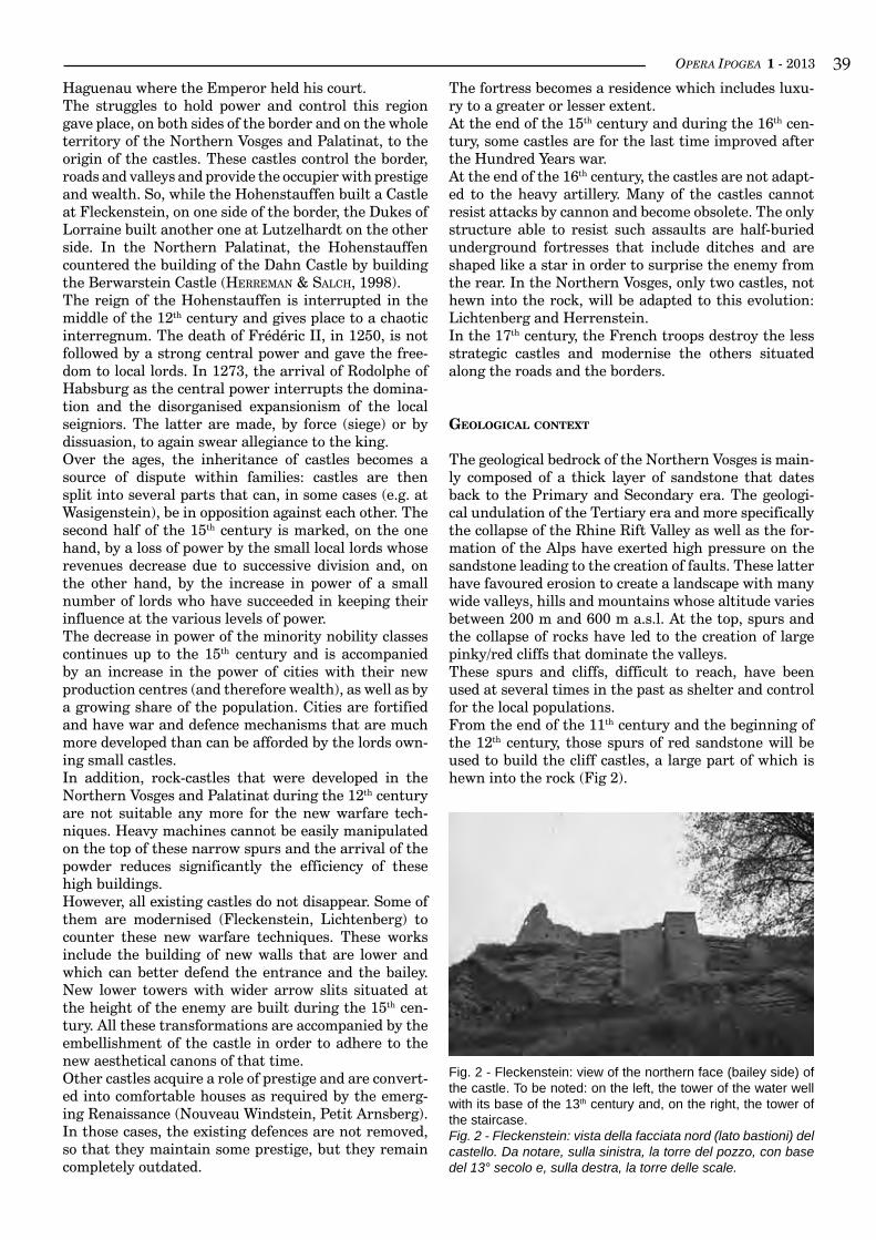
OPERA IPOGEA 1 - 2013 ��Haguenau where the Emperor held his court.The struggles to hold power and control this region gave place, on both sides of the border and on the whole territory of the Northern Vosges and Palatinat, to the origin of the castles. These castles control the border, roads and valleys and provide the occupier with prestige and wealth. So, while the Hohenstauffen built a Castle at Fleckenstein, on one side of the border, the Dukes of Lorraine built another one at Lutzelhardt on the other side. In the Northern Palatinat, the Hohenstauffen countered the building of the Dahn Castle by building the Berwarstein Castle (herreMan & salCh, 1998).The reign of the Hohenstauffen is interrupted in the middle of the 12th century and gives place to a chaotic interregnum. The death of Frédéric II, in 1250, is not followed by a strong central power and gave the free-dom to local lords. In 1273, the arrival of Rodolphe of Habsburg as the central power interrupts the domina-tion and the disorganised expansionism of the local seigniors. The latter are made, by force (siege) or by dissuasion, to again swear allegiance to the king.Over the ages, the inheritance of castles becomes a source of dispute within families: castles are then split into several parts that can, in some cases (e.g. at Wasigenstein), be in opposition against each other. The second half of the 15th century is marked, on the one hand, by a loss of power by the small local lords whose revenues decrease due to successive division and, on the other hand, by the increase in power of a small number of lords who have succeeded in keeping their influence at the various levels of power.The decrease in power of the minority nobility classes continues up to the 15th century and is accompanied by an increase in the power of cities with their new production centres (and therefore wealth), as well as by a growing share of the population. Cities are fortified and have war and defence mechanisms that are much more developed than can be afforded by the lords own-ing small castles.In addition, rock-castles that were developed in the Northern Vosges and Palatinat during the 12th century are not suitable any more for the new warfare tech-niques. Heavy machines cannot be easily manipulated on the top of these narrow spurs and the arrival of the powder reduces significantly the efficiency of these high buildings.However, all existing castles do not disappear. Some of them are modernised (Fleckenstein, Lichtenberg) to counter these new warfare techniques. These works include the building of new walls that are lower and which can better defend the entrance and the bailey. New lower towers with wider arrow slits situated at the height of the enemy are built during the 15th cen-tury. All these transformations are accompanied by the embellishment of the castle in order to adhere to the new aesthetical canons of that time.Other castles acquire a role of prestige and are convert-ed into comfortable houses as required by the emerg-ing Renaissance (Nouveau Windstein, Petit Arnsberg). In those cases, the existing defences are not removed, so that they maintain some prestige, but they remain completely outdated.
The fortress becomes a residence which includes luxu-ry to a greater or lesser extent.At the end of the 15th century and during the 16th cen-tury, some castles are for the last time improved after the Hundred Years war.At the end of the 16th century, the castles are not adapt-ed to the heavy artillery. Many of the castles cannot resist attacks by cannon and become obsolete. The only structure able to resist such assaults are half-buried underground fortresses that include ditches and are shaped like a star in order to surprise the enemy from the rear. In the Northern Vosges, only two castles, not hewn into the rock, will be adapted to this evolution: Lichtenberg and Herrenstein.In the 17th century, the French troops destroy the less strategic castles and modernise the others situated along the roads and the borders.
GeoloGical conTexT
The geological bedrock of the Northern Vosges is main-ly composed of a thick layer of sandstone that dates back to the Primary and Secondary era. The geologi-cal undulation of the Tertiary era and more specifically the collapse of the Rhine Rift Valley as well as the for-mation of the Alps have exerted high pressure on the sandstone leading to the creation of faults. These latter have favoured erosion to create a landscape with many wide valleys, hills and mountains whose altitude varies between 200 m and 600 m a.s.l. At the top, spurs and the collapse of rocks have led to the creation of large pinky/red cliffs that dominate the valleys.These spurs and cliffs, difficult to reach, have been used at several times in the past as shelter and control for the local populations.From the end of the 11th century and the beginning of the 12th century, those spurs of red sandstone will be used to build the cliff castles, a large part of which is hewn into the rock (Fig 2).
Fig. 2 - Fleckenstein: view of the northern face (bailey side) of the castle. To be noted: on the left, the tower of the water well with its base of the 13th century and, on the right, the tower of the staircase.Fig. 2 - Fleckenstein: vista della facciata nord (lato bastioni) del castello. Da notare, sulla sinistra, la torre del pozzo, con base del 13° secolo e, sulla destra, la torre delle scale.
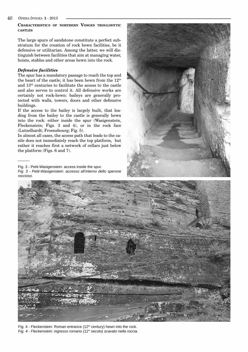
OPERA IPOGEA 1 - 2013�0cHaracTerisTics of norTHern vosGes TroGlodyTic casTles
The large spurs of sandstone constitute a perfect sub-stratum for the creation of rock hewn facilities, be it defensive or utilitarian. Among the latter, we will dis-tinguish between facilities that aim at managing water, hoists, stables and other areas hewn into the rock.
Defensive facilitiesThe spur has a mandatory passage to reach the top and the heart of the castle; it has been hewn from the 12th and 13th centuries to facilitate the access to the castle and also serves to control it. All defensive works are certainly not rock-hewn: baileys are generally pro-tected with walls, towers, doors and other defensive buildings.If the access to the bailey is largely built, that lea-ding from the bailey to the castle is generally hewn into the rock: either inside the spur (Wasigenstein, Fleckenstein; Figs. 3 and 4), or in the rock face (Lutzelhardt; Froensbourg; Fig. 5).In almost all cases, the access path that leads to the ca-stle does not immediately reach the top platform, but rather it reaches first a network of cellars just below the platform (Figs. 6 and 7).
Fig. 3 - Petit-Wasigenstein: access inside the spur.Fig. 3 - Petit-Wasigenstein: accesso all’interno dello sperone roccioso.
Fig. 4 - Fleckenstein: Roman entrance (12th century) hewn into the rock.Fig. 4 - Fleckenstein: ingresso romano (12° secolo) scavato nella roccia.
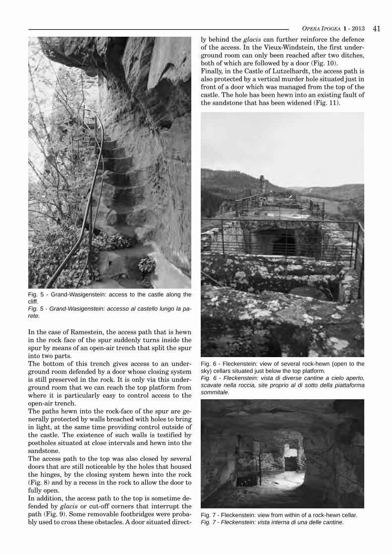
OPERA IPOGEA 1 - 2013 ��
Fig. 5 - Grand-Wasigenstein: access to the castle along the cliff.Fig. 5 - Grand-Wasigenstein: accesso al castello lungo la pa-rete.
In the case of Ramestein, the access path that is hewn in the rock face of the spur suddenly turns inside the spur by means of an open-air trench that split the spur into two parts.The bottom of this trench gives access to an under-ground room defended by a door whose closing system is still preserved in the rock. It is only via this under-ground room that we can reach the top platform from where it is particularly easy to control access to the open-air trench.The paths hewn into the rock-face of the spur are ge-nerally protected by walls breached with holes to bring in light, at the same time providing control outside of the castle. The existence of such walls is testified by postholes situated at close intervals and hewn into the sandstone.The access path to the top was also closed by several doors that are still noticeable by the holes that housed the hinges, by the closing system hewn into the rock (Fig. 8) and by a recess in the rock to allow the door to fully open.In addition, the access path to the top is sometime de-fended by glacis or cut-off corners that interrupt the path (Fig. 9). Some removable footbridges were proba-bly used to cross these obstacles. A door situated direct-
Fig. 6 - Fleckenstein: view of several rock-hewn (open to the sky) cellars situated just below the top platform.Fig. 6 - Fleckenstein: vista di diverse cantine a cielo aperto, scavate nella roccia, site proprio al di sotto della piattaforma sommitale.
Fig. 7 - Fleckenstein: view from within of a rock-hewn cellar.Fig. 7 - Fleckenstein: vista interna di una delle cantine.
ly behind the glacis can further reinforce the defence of the access. In the Vieux-Windstein, the first under-ground room can only been reached after two ditches, both of which are followed by a door (Fig. 10).Finally, in the Castle of Lutzelhardt, the access path is also protected by a vertical murder hole situated just in front of a door which was managed from the top of the castle. The hole has been hewn into an existing fault of the sandstone that has been widened (Fig. 11).
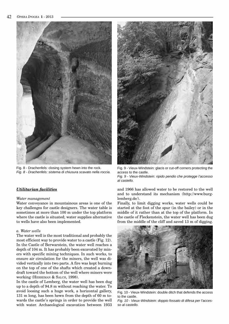
OPERA IPOGEA 1 - 2013��
and 1966 has allowed water to be restored to the well and to understand its mechanism (http://www.burg-lemberg.de/).Finally, to limit digging works, water wells could be started at the foot of the spur (in the bailey) or in the middle of it rather than at the top of the platform. In the castle of Fleckenstein, the water well has been dug from the middle of the cliff and saved 13 m of digging.
Fig. 9 - Vieux-Windstein: glacis or cut-off corners protecting the access to the castle.Fig. 9 - Vieux-Windstein: ripido pendio che protegge l’accesso al castello.
Fig. 10 - Vieux-Windstein: double ditch that defends the access to the castle.Fig. 10 - Vieux-Windstein: doppio fossato di difesa per l’acces-so al castello.
Fig. 8 - Drachenfels: closing system hewn into the rock.Fig. 8 - Drachenfels: sistema di chiusura scavato nella roccia.
Utilitarian facilities
Water managementWater conveyance in mountainous areas is one of the key challenges for castle designers. The water table is sometimes at more than 100 m under the top platform where the castle is situated; water supplies alternative to wells have also been implemented.
a. Water wellsThe water well is the most traditional and probably the most efficient way to provide water to a castle (Fig. 12). In the Castle of Berwarstein, the water well reaches a depth of 104 m. It has probably been excavated by min-ers with specific mining techniques. In such works, to ensure air circulation for the miners, the well was di-vided vertically into two parts. A fire was kept burning on the top of one of the shafts which created a down-draft toward the bottom of the well where miners were working (herreMan & salCh, 1998).In the castle of Lemberg, the water well has been dug up to a depth of 94.8 m without reaching the water. To avoid loosing such a huge work, a horizontal gallery, 131 m long, has been hewn from the depth of 60 m to-wards the castle’s springs in order to provide the well with water. Archaeological excavation between 1933
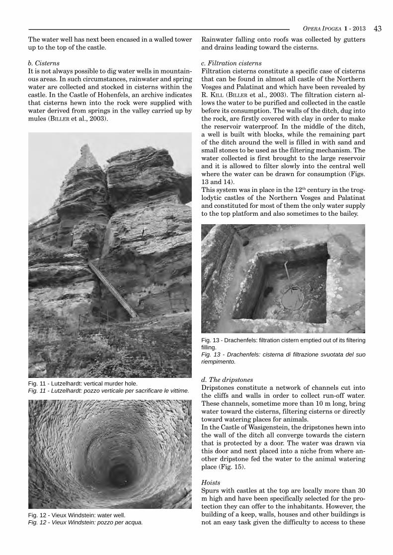
OPERA IPOGEA 1 - 2013 ��The water well has next been encased in a walled tower up to the top of the castle.
b. CisternsIt is not always possible to dig water wells in mountain-ous areas. In such circumstances, rainwater and spring water are collected and stocked in cisterns within the castle. In the Castle of Hohenfels, an archive indicates that cisterns hewn into the rock were supplied with water derived from springs in the valley carried up by mules (biller et al., 2003).
Fig. 11 - Lutzelhardt: vertical murder hole.Fig. 11 - Lutzelhardt: pozzo verticale per sacrificare le vittime.
Fig. 12 - Vieux Windstein: water well.Fig. 12 - Vieux Windstein: pozzo per acqua.
Rainwater falling onto roofs was collected by gutters and drains leading toward the cisterns.
c. Filtration cisternsFiltration cisterns constitute a specific case of cisterns that can be found in almost all castle of the Northern Vosges and Palatinat and which have been revealed by R. kill (biller et al., 2003). The filtration cistern al-lows the water to be purified and collected in the castle before its consumption. The walls of the ditch, dug into the rock, are firstly covered with clay in order to make the reservoir waterproof. In the middle of the ditch, a well is built with blocks, while the remaining part of the ditch around the well is filled in with sand and small stones to be used as the filtering mechanism. The water collected is first brought to the large reservoir and it is allowed to filter slowly into the central well where the water can be drawn for consumption (Figs. 13 and 14).This system was in place in the 12th century in the trog-lodytic castles of the Northern Vosges and Palatinat and constituted for most of them the only water supply to the top platform and also sometimes to the bailey.
Fig. 13 - Drachenfels: filtration cistern emptied out of its filtering filling.Fig. 13 - Drachenfels: cisterna di filtrazione svuotata del suo riempimento.
d. The dripstonesDripstones constitute a network of channels cut into the cliffs and walls in order to collect run-off water. These channels, sometime more than 10 m long, bring water toward the cisterns, filtering cisterns or directly toward watering places for animals.In the Castle of Wasigenstein, the dripstones hewn into the wall of the ditch all converge towards the cistern that is protected by a door. The water was drawn via this door and next placed into a niche from where an-other dripstone fed the water to the animal watering place (Fig. 15).
HoistsSpurs with castles at the top are locally more than 30 m high and have been specifically selected for the pro-tection they can offer to the inhabitants. However, the building of a keep, walls, houses and other buildings is not an easy task given the difficulty to access to these
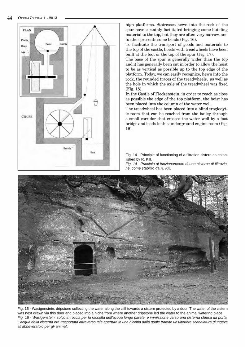
OPERA IPOGEA 1 - 2013��high platforms. Staircases hewn into the rock of the spur have certainly facilitated bringing some building material to the top, but they are often very narrow, and further presents some bends (Fig. 16).To facilitate the transport of goods and materials to the top of the castle, hoists with treadwheels have been built at the foot or the top of the spur (Fig. 17).The base of the spur is generally wider than the top and it has generally been cut in order to allow the hoist to be as vertical as possible up to the top edge of the platform. Today, we can easily recognize, hewn into the rock, the rounded traces of the treadwheels, as well as the hole in which the axle of the treadwheel was fixed (Fig. 18).In the Castle of Fleckenstein, in order to reach as close as possible the edge of the top platform, the hoist has been placed into the column of the water well.The treadwheel has been placed into a blind troglodyt-ic room that can be reached from the bailey through a small corridor that crosses the water well by a foot bridge and leads to this underground engine room (Fig. 19).
Fig. 14 - Principle of functioning of a filtration cistern as estab-lished by R. Kill.Fig. 14 - Principio di funzionamento di una cisterna di filtrazio-ne, come stabilito da R. Kill.
Fig. 15 - Wasigenstein: dripstone collecting the water along the cliff towards a cistern protected by a door. The water of the cistern was next drawn via this door and placed into a niche from where another dripstone led the water to the animal watering place.Fig. 15 - Wasigenstein: solco in roccia per la raccolta dell’acqua lungo parete, e immissione verso una cisterna chiusa da porta. L’acqua della cisterna era trasportata attraverso tale apertura in una nicchia dalla quale tramite un’ulteriore scanalatura giungeva all’abbeveratoio per gli animali.

OPERA IPOGEA 1 - 2013 ��
Fig. 16 - Fleckenstein: spiral staircase.Fig. 16 - Fleckenstein: scala a chiocciola.
Fig. 17 - Dahn: treadwheel of a hoist recreated.Fig. 17 - Dahn: ruota di un argano ricostruito.
At the extreme southern end of the Castle of Falkenstein, the rising column of the hoist has been created by dig-ging into the rock along its total height, thus crossing the primitive staircase that was modified (herreMan & salCh, 1998; Fig. 20).
StablesHorses have received specific attention in Northern Vosges and Palatinat castles. The bailey has special fa-cilities to house them.
Fig. 18 - Froensbourg: place of a former treadwheel.Fig. 18 - Froensbourg: sito di una non più esistente ruota per argano.
In the Castle of Falkenstein, herreMann & salCh (1998) have identified two stables. A first one from the 12th century can be recognized with its mangers, together with a round pit which was probably used to drain the slurry. A second one dates back to 1575 and has been created in what was described in 1474 as a wine cellar.The ten mangers have been realized in a former cup-board so we can assume that this room had another function before being used as wine cellar and stable. The tradition mentions it as a guard room.In the castle of Alt-Dahn, the artillery tower of the 15th century built along the cliff gives access to a troglodytic stable (Fig. 21).We find here again mangers and drains leading to a slurry pit. The room is totally hewn into the rock and is lit by a small window splayed towards the inside in order to maximise the light penetrating the room.In other castles, like Fleckenstein and Windstein, sta-bles are not troglodytic, but simply constructed in the bailey. They are recognisable thanks to the rings hewn into the rock (Fig. 22) and the watering place.According to herreMann & salCh (1998) the stables of the castle belonging to the Stauffen were generally out-side in the bailey, while those belonging to Lords were generally hewn into the rock.
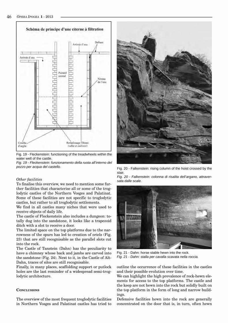
OPERA IPOGEA 1 - 2013��
Fig. 19 - Fleckenstein: functioning of the treadwheels within the water well of the castle.Fig. 19 - Fleckenstein: funzionamento della ruota all’interno del pozzo per acqua del castello.
Other facilitiesTo finalise this overview, we need to mention some fur-ther facilities that characterise all or some of the trog-lodytic castles of the Northern Vosges and Palatinat. Some of these facilities are not specific to troglodytic castles, but rather to all troglodytic settlements.We find in all castles many niches that were used to receive objects of daily life.The castle of Fleckenstein also includes a dungeon: to-tally dug into the sandstone, it looks like a trapezoid ditch with a slot to receive a door.The limited space on the top platforms due to the nar-rowness of the spurs has led to creation of oriels (Fig. 23) that are still recognisable as the parallel slots cut into the rock.The Castle of Tanstein (Dahn) has the peculiarity to have a chimney whose back and jambs are carved into the sandstone (Fig. 24). Next to it, in the Castle of Alt-Dahn, traces of silos are still recognisable.Finally, in many places, scaffolding support or putlock holes are the last reminder of a widespread semi-trog-lodytic architecture.
conclusions
The overview of the most frequent troglodytic facilities in Northern Vosges and Palatinat castles has tried to
Fig. 21 - Dahn: horse stable hewn into the rock.Fig. 21 - Dahn: stalla per cavalla scavata nella roccia.
outline the occurrence of these facilities in the castles and their possible evolution over time.We can highlight the high prevalence of rock-hewn ele-ments for access to the top platforms. The castle and the keep are not hewn into the rock but solidly built on the top platform in the form of long and narrow build-ings.Defensive facilities hewn into the rock are generally concentrated on the door that is, in turn, often hewn
Fig. 20 - Falkenstein: rising column of the hoist crossed by the stair.Fig. 20 - Falkenstein: colonna di risalita dell’argano, attraver-sata dalle scale.
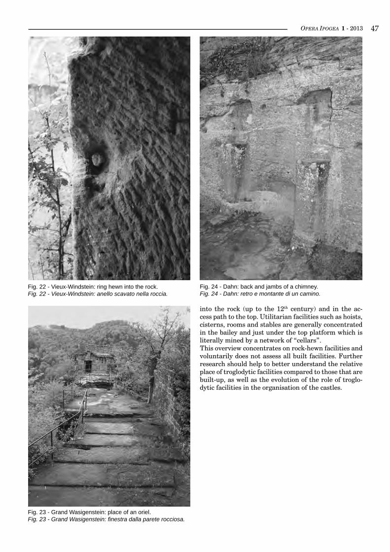
OPERA IPOGEA 1 - 2013 ��
Fig. 22 - Vieux-Windstein: ring hewn into the rock.Fig. 22 - Vieux-Windstein: anello scavato nella roccia.
into the rock (up to the 12th century) and in the ac-cess path to the top. Utilitarian facilities such as hoists, cisterns, rooms and stables are generally concentrated in the bailey and just under the top platform which is literally mined by a network of “cellars”.This overview concentrates on rock-hewn facilities and voluntarily does not assess all built facilities. Further research should help to better understand the relative place of troglodytic facilities compared to those that are built-up, as well as the evolution of the role of troglo-dytic facilities in the organisation of the castles.
Fig. 24 - Dahn: back and jambs of a chimney.Fig. 24 - Dahn: retro e montante di un camino.
Fig. 23 - Grand Wasigenstein: place of an oriel. Fig. 23 - Grand Wasigenstein: finestra dalla parete rocciosa.
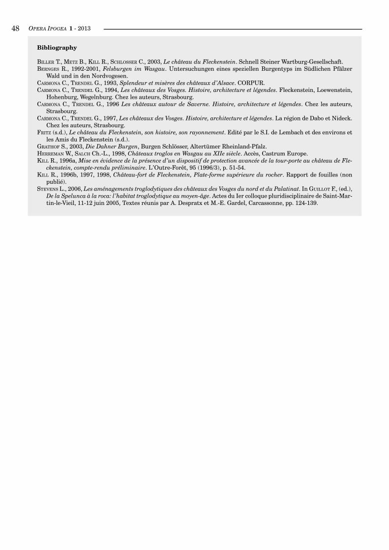
OPERA IPOGEA 1 - 2013��
bibliography
biller t., Metz b., kill r., sChlosser C., 2003, Le château du Fleckenstein. Schnell Steiner Wartburg-Gesellschaft.bernGes R., 1992-2001, Felsburgen im Wasgau. Untersuchungen eines speziellen Burgentyps im Südlichen Pfälzer
Wald und in den Nordvogesen.CarMona C., trendel G., 1993, Splendeur et misères des châteaux d’Alsace. CORPUR.CarMona C., trendel G., 1994, Les châteaux des Vosges. Histoire, architecture et légendes. Fleckenstein, Loewenstein,
Hohenburg, Wegelnburg. Chez les auteurs, Strasbourg.CarMona C., trendel G., 1996 Les châteaux autour de Saverne. Histoire, architecture et légendes. Chez les auteurs,
Strasbourg.CarMona C., trendel G., 1997, Les châteaux des Vosges. Histoire, architecture et légendes. La région de Dabo et Nideck.
Chez les auteurs, Strasbourg.Fritz (s.d.), Le château du Fleckenstein, son histoire, son rayonnement. Edité par le S.I. de Lembach et des environs et
les Amis du Fleckenstein (s.d.).GrathoF S., 2003, Die Dahner Burgen, Burgen Schlösser, Altertümer Rheinland-Pfalz.herreMan W., salCh Ch.-L., 1998, Châteaux troglos en Wasgau au XIIe siècle. Accès, Castrum Europe.kill R., 1996a, Mise en évidence de la présence d’un dispositif de protection avancée de la tour-porte au château de Fle-
ckenstein, compte-rendu préliminaire. L’Outre-Forêt, 95 (1996/3), p. 51-54.kill R., 1996b, 1997, 1998, Château-fort de Fleckenstein, Plate-forme supérieure du rocher. Rapport de fouilles (non
publié).stevens L., 2006, Les aménagements troglodytiques des châteaux des Vosges du nord et du Palatinat. In Guillot F., (ed.),
De la Spelunca à la roca: l’habitat troglodytique au moyen-âge. Actes du Ier colloque pluridisciplinaire de Saint-Mar-tin-le-Vieil, 11-12 juin 2005, Textes réunis par A. Despratx et M.-E. Gardel, Carcassonne, pp. 124-139.
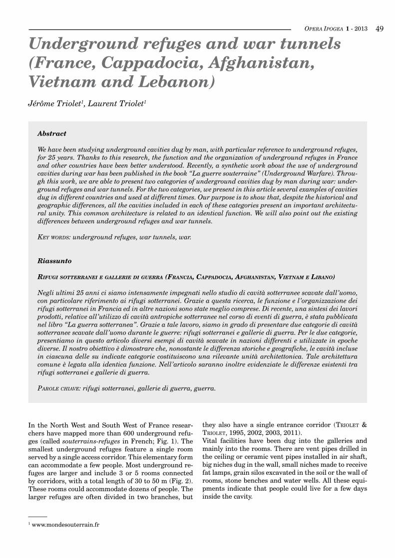
OPERA IPOGEA 1 - 2013 ��
Underground refuges and war tunnels (France, Cappadocia, Afghanistan,Vietnam and Lebanon)Jérôme Triolet1, Laurent Triolet1
1 www.mondesouterrain.fr
Abstract
We have been studying underground cavities dug by man, with particular reference to underground refuges, for 25 years. Thanks to this research, the function and the organization of underground refuges in France and other countries have been better understood. Recently, a synthetic work about the use of underground cavities during war has been published in the book “La guerre souterraine” (Underground Warfare). Throu-gh this work, we are able to present two categories of underground cavities dug by man during war: under-ground refuges and war tunnels. For the two categories, we present in this article several examples of cavities dug in different countries and used at different times. Our purpose is to show that, despite the historical and geographic differences, all the cavities included in each of these categories present an important architectu-ral unity. This common architecture is related to an identical function. We will also point out the existing differences between underground refuges and war tunnels.
key worDS: underground refuges, war tunnels, war.
Riassunto
rifugi sotterranei e gaLLerie di guerra (francia, cappadocia, afghanistan, vietnam e Libano)
Negli ultimi 25 anni ci siamo intensamente impegnati nello studio di cavità sotterranee scavate dall’uomo, con particolare riferimento ai rifugi sotterranei. Grazie a questa ricerca, le funzione e l’organizzazione dei rifugi sotterranei in Francia ed in altre nazioni sono state meglio comprese. Di recente, una sintesi dei lavori prodotti, relative all’utilizzo di cavità antropiche sotterranee nel corso di eventi di guerra, è stata pubblicata nel libro “La guerra sotterranea”. Grazie a tale lavoro, siamo in grado di presentare due categorie di cavità sotterranee scavate dall’uomo durante le guerre: rifugi sotterranei e gallerie di guerra. Per le due categorie, presentiamo in questo articolo diversi esempi di cavità scavate in nazioni differenti e utilizzate in epoche diverse. Il nostro obiettivo è dimostrare che, nonostante le differenza storiche e geografiche, le cavità incluse in ciascuna delle su indicate categorie costituiscono una rilevante unità architettonica. Tale architettura comune è legata alla identica funzione. Nell’articolo saranno inoltre evidenziate le differenze esistenti tra rifugi sotterranei e gallerie di guerra.
Parole chiave: rifugi sotterranei, gallerie di guerra, guerra.
In the North West and South West of France resear-chers have mapped more than 600 underground refu-ges (called souterrains-refuges in French; Fig. 1). The smallest underground refuges feature a single room served by a single access corridor. This elementary form can accommodate a few people. Most underground re-fuges are larger and include 3 or 5 rooms connected by corridors, with a total length of 30 to 50 m (Fig. 2). These rooms could accommodate dozens of people. The larger refuges are often divided in two branches, but
they also have a single entrance corridor (triolet & triolet, 1995, 2002, 2003, 2011).Vital facilities have been dug into the galleries and mainly into the rooms. There are vent pipes drilled in the ceiling or ceramic vent pipes installed in air shaft, big niches dug in the wall, small niches made to receive fat lamps, grain silos excavated in the soil or the wall of rooms, stone benches and water wells. All these equi-pments indicate that people could live for a few days inside the cavity.
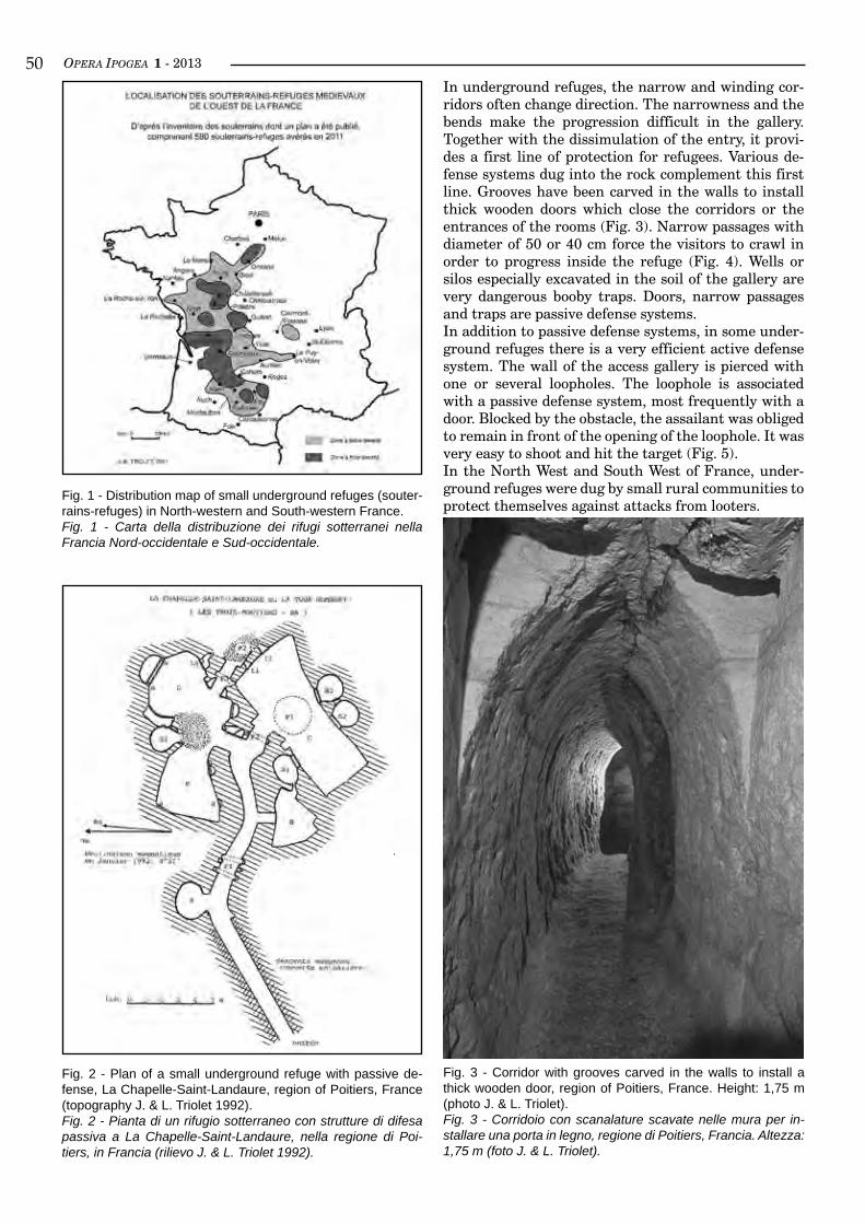
OPERA IPOGEA 1 - 2013�0In underground refuges, the narrow and winding cor-ridors often change direction. The narrowness and the bends make the progression difficult in the gallery. Together with the dissimulation of the entry, it provi-des a first line of protection for refugees. Various de-fense systems dug into the rock complement this first line. Grooves have been carved in the walls to install thick wooden doors which close the corridors or the entrances of the rooms (Fig. 3). Narrow passages with diameter of 50 or 40 cm force the visitors to crawl in order to progress inside the refuge (Fig. 4). Wells or silos especially excavated in the soil of the gallery are very dangerous booby traps. Doors, narrow passages and traps are passive defense systems.In addition to passive defense systems, in some under-ground refuges there is a very efficient active defense system. The wall of the access gallery is pierced with one or several loopholes. The loophole is associated with a passive defense system, most frequently with a door. Blocked by the obstacle, the assailant was obliged to remain in front of the opening of the loophole. It was very easy to shoot and hit the target (Fig. 5).In the North West and South West of France, under-ground refuges were dug by small rural communities to protect themselves against attacks from looters.
Fig. 1 - Distribution map of small underground refuges (souter-rains-refuges) in North-western and South-western France.Fig. 1 - Carta della distribuzione dei rifugi sotterranei nella Francia Nord-occidentale e Sud-occidentale.
Fig. 2 - Plan of a small underground refuge with passive de-fense, La Chapelle-Saint-Landaure, region of Poitiers, France (topography J. & L. Triolet 1992).Fig. 2 - Pianta di un rifugio sotterraneo con strutture di difesa passiva a La Chapelle-Saint-Landaure, nella regione di Poi-tiers, in Francia (rilievo J. & L. Triolet 1992).
Fig. 3 - Corridor with grooves carved in the walls to install a thick wooden door, region of Poitiers, France. Height: 1,75 m (photo J. & L. Triolet).Fig. 3 - Corridoio con scanalature scavate nelle mura per in-stallare una porta in legno, regione di Poitiers, Francia. Altezza: 1,75 m (foto J. & L. Triolet).
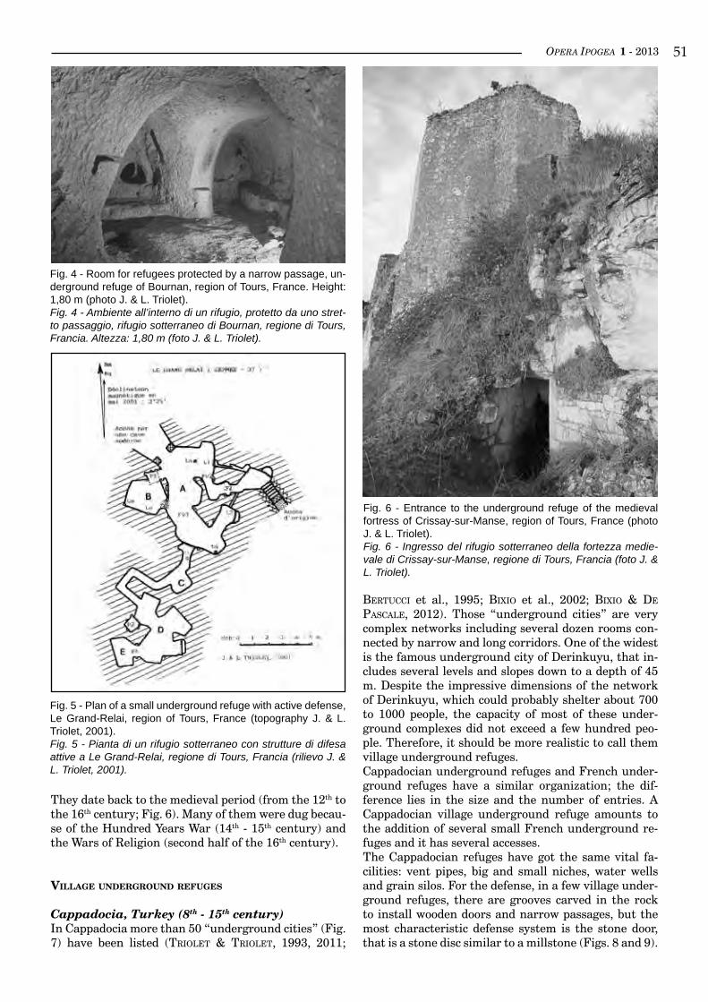
OPERA IPOGEA 1 - 2013 ��
Fig. 4 - Room for refugees protected by a narrow passage, un-derground refuge of Bournan, region of Tours, France. Height: 1,80 m (photo J. & L. Triolet).Fig. 4 - Ambiente all’interno di un rifugio, protetto da uno stret-to passaggio, rifugio sotterraneo di Bournan, regione di Tours, Francia. Altezza: 1,80 m (foto J. & L. Triolet).
Fig. 5 - Plan of a small underground refuge with active defense, Le Grand-Relai, region of Tours, France (topography J. & L. Triolet, 2001).Fig. 5 - Pianta di un rifugio sotterraneo con strutture di difesa attive a Le Grand-Relai, regione di Tours, Francia (rilievo J. & L. Triolet, 2001).
They date back to the medieval period (from the 12th to the 16th century; Fig. 6). Many of them were dug becau-se of the Hundred Years War (14th - 15th century) and the Wars of Religion (second half of the 16th century).
villaGe underGround refuGes
Cappadocia, Turkey (8th - 15th century)In Cappadocia more than 50 “underground cities” (Fig. 7) have been listed (triolet & triolet, 1993, 2011;
Fig. 6 - Entrance to the underground refuge of the medieval fortress of Crissay-sur-Manse, region of Tours, France (photo J. & L. Triolet).Fig. 6 - Ingresso del rifugio sotterraneo della fortezza medie-vale di Crissay-sur-Manse, regione di Tours, Francia (foto J. & L. Triolet).
bertuCCi et al., 1995; bixio et al., 2002; bixio & de PasCale, 2012). Those “underground cities” are very complex networks including several dozen rooms con-nected by narrow and long corridors. One of the widest is the famous underground city of Derinkuyu, that in-cludes several levels and slopes down to a depth of 45 m. Despite the impressive dimensions of the network of Derinkuyu, which could probably shelter about 700 to 1000 people, the capacity of most of these under-ground complexes did not exceed a few hundred peo-ple. Therefore, it should be more realistic to call them village underground refuges.Cappadocian underground refuges and French under-ground refuges have a similar organization; the dif-ference lies in the size and the number of entries. A Cappadocian village underground refuge amounts to the addition of several small French underground re-fuges and it has several accesses.The Cappadocian refuges have got the same vital fa-cilities: vent pipes, big and small niches, water wells and grain silos. For the defense, in a few village under-ground refuges, there are grooves carved in the rock to install wooden doors and narrow passages, but the most characteristic defense system is the stone door, that is a stone disc similar to a millstone (Figs. 8 and 9).
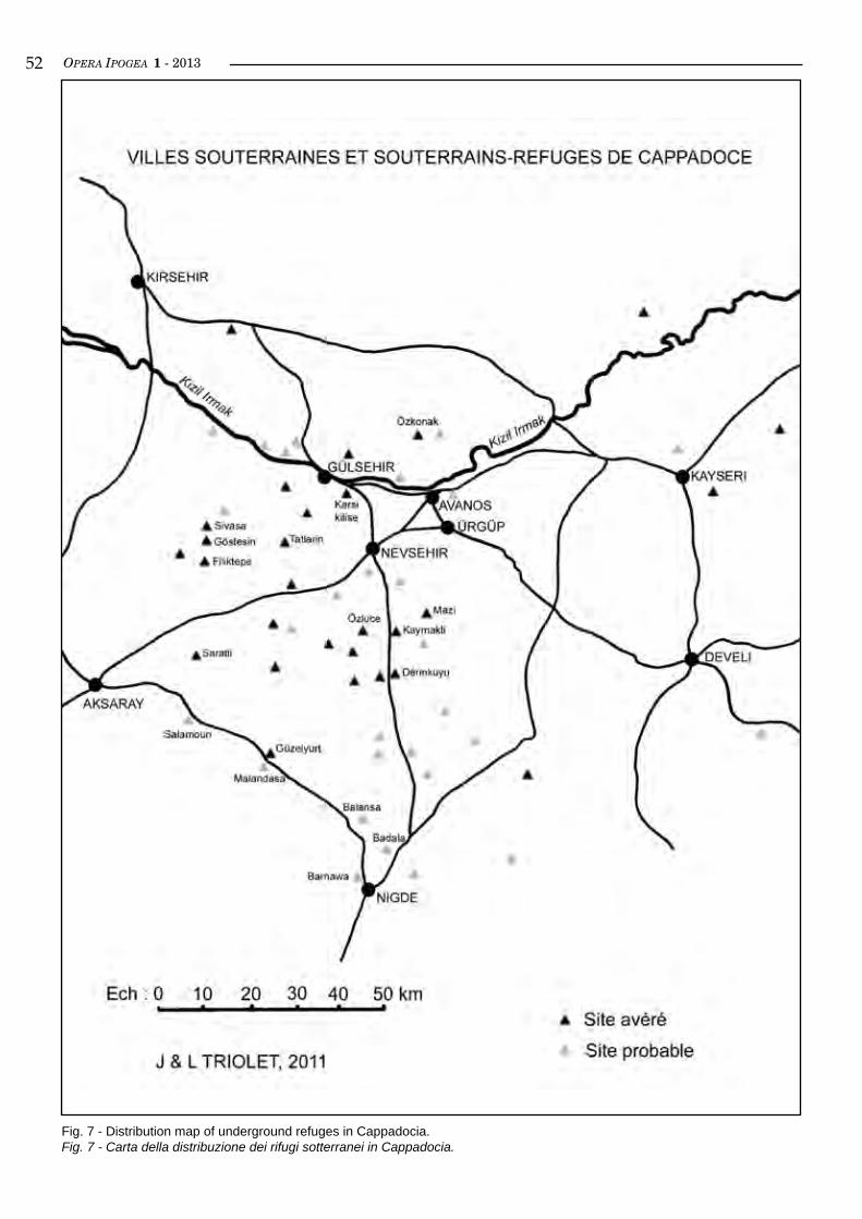
OPERA IPOGEA 1 - 2013��
Fig. 7 - Distribution map of underground refuges in Cappadocia.Fig. 7 - Carta della distribuzione dei rifugi sotterranei in Cappadocia.
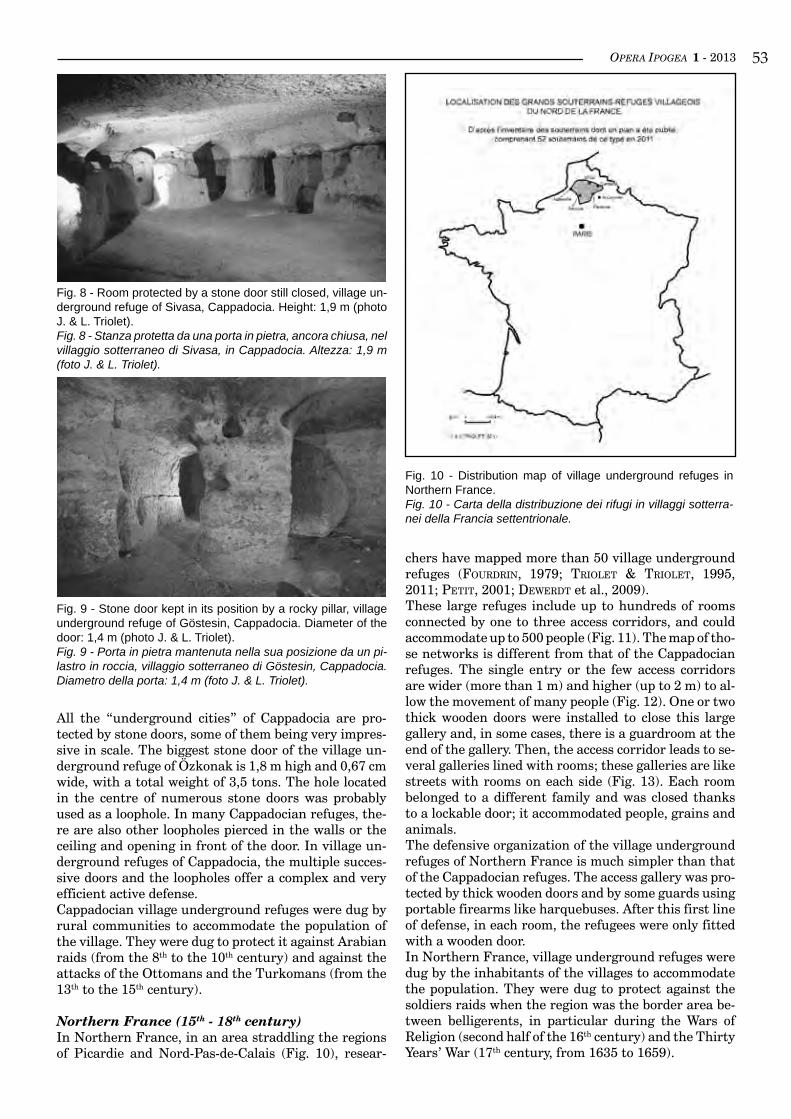
OPERA IPOGEA 1 - 2013 ��
Fig. 8 - Room protected by a stone door still closed, village un-derground refuge of Sivasa, Cappadocia. Height: 1,9 m (photo J. & L. Triolet).Fig. 8 - Stanza protetta da una porta in pietra, ancora chiusa, nel villaggio sotterraneo di Sivasa, in Cappadocia. Altezza: 1,9 m(foto J. & L. Triolet).
Fig. 9 - Stone door kept in its position by a rocky pillar, village underground refuge of Göstesin, Cappadocia. Diameter of the door: 1,4 m (photo J. & L. Triolet).Fig. 9 - Porta in pietra mantenuta nella sua posizione da un pi-lastro in roccia, villaggio sotterraneo di Göstesin, Cappadocia. Diametro della porta: 1,4 m (foto J. & L. Triolet).
All the “underground cities” of Cappadocia are pro-tected by stone doors, some of them being very impres-sive in scale. The biggest stone door of the village un-derground refuge of Özkonak is 1,8 m high and 0,67 cm wide, with a total weight of 3,5 tons. The hole located in the centre of numerous stone doors was probably used as a loophole. In many Cappadocian refuges, the-re are also other loopholes pierced in the walls or the ceiling and opening in front of the door. In village un-derground refuges of Cappadocia, the multiple succes-sive doors and the loopholes offer a complex and very efficient active defense.Cappadocian village underground refuges were dug by rural communities to accommodate the population of the village. They were dug to protect it against Arabian raids (from the 8th to the 10th century) and against the attacks of the Ottomans and the Turkomans (from the 13th to the 15th century).
Northern France (15th - 18th century)In Northern France, in an area straddling the regions of Picardie and Nord-Pas-de-Calais (Fig. 10), resear-
Fig. 10 - Distribution map of village underground refuges in Northern France.Fig. 10 - Carta della distribuzione dei rifugi in villaggi sotterra-nei della Francia settentrionale.
chers have mapped more than 50 village underground refuges (Fourdrin, 1979; triolet & triolet, 1995, 2011; Petit, 2001; deWerdt et al., 2009).These large refuges include up to hundreds of rooms connected by one to three access corridors, and could accommodate up to 500 people (Fig. 11). The map of tho-se networks is different from that of the Cappadocian refuges. The single entry or the few access corridors are wider (more than 1 m) and higher (up to 2 m) to al-low the movement of many people (Fig. 12). One or two thick wooden doors were installed to close this large gallery and, in some cases, there is a guardroom at the end of the gallery. Then, the access corridor leads to se-veral galleries lined with rooms; these galleries are like streets with rooms on each side (Fig. 13). Each room belonged to a different family and was closed thanks to a lockable door; it accommodated people, grains and animals.The defensive organization of the village underground refuges of Northern France is much simpler than that of the Cappadocian refuges. The access gallery was pro-tected by thick wooden doors and by some guards using portable firearms like harquebuses. After this first line of defense, in each room, the refugees were only fitted with a wooden door.In Northern France, village underground refuges were dug by the inhabitants of the villages to accommodate the population. They were dug to protect against the soldiers raids when the region was the border area be-tween belligerents, in particular during the Wars of Religion (second half of the 16th century) and the Thirty Years’ War (17th century, from 1635 to 1659).
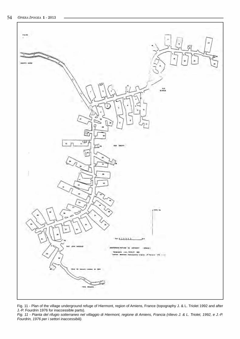
OPERA IPOGEA 1 - 2013��
Fig. 11 - Plan of the village underground refuge of Hiermont, region of Amiens, France (topography J. & L. Triolet 1992 and after J.-P. Fourdrin 1976 for inaccessible parts).Fig. 11 - Pianta del rifugio sotterraneo nel villaggio di Hiermont, regione di Amiens, Francia (rilievo J. & L. Triolet, 1992, e J.-P. Fourdrin, 1976 per i settori inaccessibili).
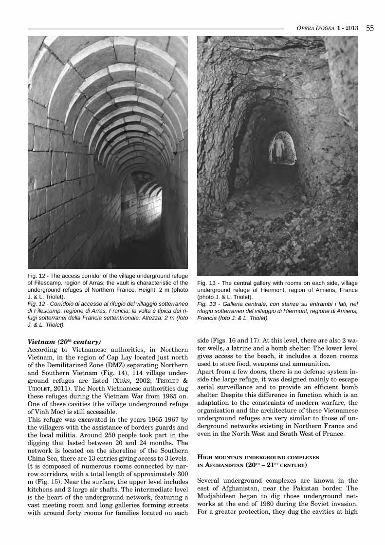
OPERA IPOGEA 1 - 2013 ��
Vietnam (20th century)According to Vietnamese authorities, in Northern Vietnam, in the region of Cap Lay located just north of the Demilitarized Zone (DMZ) separating Northern and Southern Vietnam (Fig. 14), 114 village under-ground refuges are listed (xuân, 2002; triolet & triolet, 2011). The North Vietnamese authorities dug these refuges during the Vietnam War from 1965 on. One of these cavities (the village underground refuge of Vinh Moc) is still accessible.This refuge was excavated in the years 1965-1967 by the villagers with the assistance of borders guards and the local militia. Around 250 people took part in the digging that lasted between 20 and 24 months. The network is located on the shoreline of the Southern China Sea, there are 13 entries giving access to 3 levels. It is composed of numerous rooms connected by nar-row corridors, with a total length of approximately 300 m (Fig. 15). Near the surface, the upper level includes kitchens and 2 large air shafts. The intermediate level is the heart of the underground network, featuring a vast meeting room and long galleries forming streets with around forty rooms for families located on each
Fig. 12 - The access corridor of the village underground refuge of Filescamp, region of Arras; the vault is characteristic of the underground refuges of Northern France. Height: 2 m (photo J. & L. Triolet).Fig. 12 - Corridoio di accesso al rifugio del villaggio sotterraneo di Filescamp, regione di Arras, Francia; la volta è tipica dei ri-fugi sotterranei della Francia settentrionale. Altezza: 2 m (foto J. & L. Triolet).
side (Figs. 16 and 17). At this level, there are also 2 wa-ter wells, a latrine and a bomb shelter. The lower level gives access to the beach, it includes a dozen rooms used to store food, weapons and ammunition.Apart from a few doors, there is no defense system in-side the large refuge, it was designed mainly to escape aerial surveillance and to provide an efficient bomb shelter. Despite this difference in function which is an adaptation to the constraints of modern warfare, the organization and the architecture of these Vietnamese underground refuges are very similar to those of un-derground networks existing in Northern France and even in the North West and South West of France.
HiGH mounTain underGround comPlexes
in afGHanisTan (20TH – 21sT cenTury)
Several underground complexes are known in the east of Afghanistan, near the Pakistan border. The Mudjahideen began to dig those underground net-works at the end of 1980 during the Soviet invasion. For a greater protection, they dug the cavities at high
Fig. 13 - The central gallery with rooms on each side, village underground refuge of Hiermont, region of Amiens, France (photo J. & L. Triolet).Fig. 13 - Galleria centrale, con stanze su entrambi i lati, nel rifugio sotterraneo del villaggio di Hiermont, regione di Amiens, Francia (foto J. & L. Triolet).
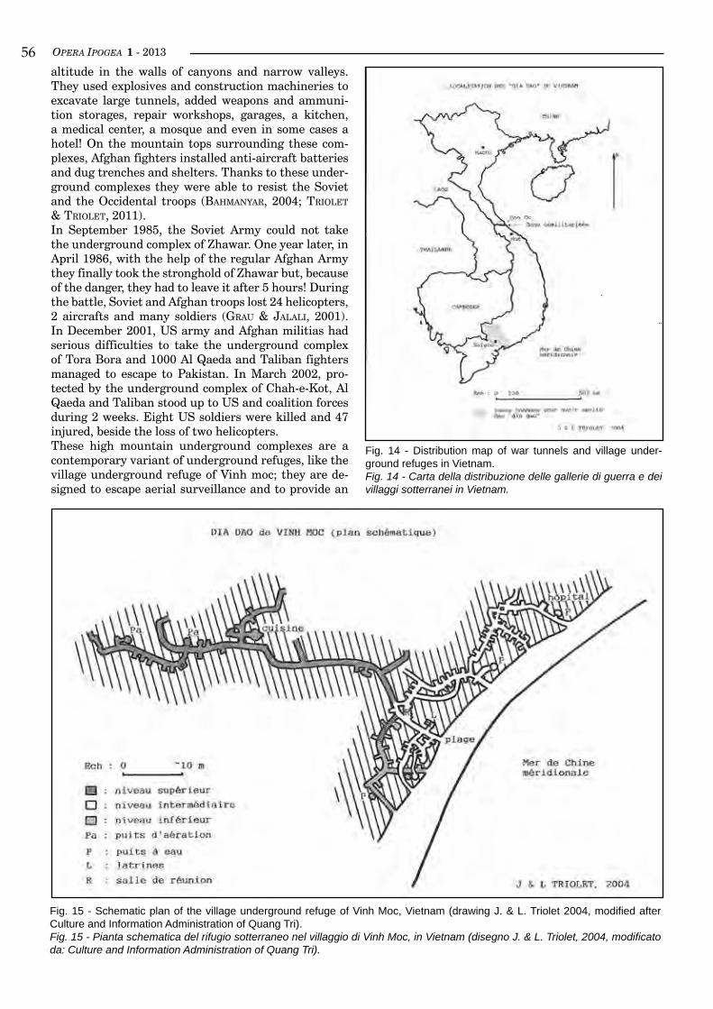
OPERA IPOGEA 1 - 2013��altitude in the walls of canyons and narrow valleys. They used explosives and construction machineries to excavate large tunnels, added weapons and ammuni-tion storages, repair workshops, garages, a kitchen, a medical center, a mosque and even in some cases a hotel! On the mountain tops surrounding these com-plexes, Afghan fighters installed anti-aircraft batteries and dug trenches and shelters. Thanks to these under-ground complexes they were able to resist the Soviet and the Occidental troops (bahManyar, 2004; triolet & triolet, 2011).In September 1985, the Soviet Army could not take the underground complex of Zhawar. One year later, in April 1986, with the help of the regular Afghan Army they finally took the stronghold of Zhawar but, because of the danger, they had to leave it after 5 hours! During the battle, Soviet and Afghan troops lost 24 helicopters, 2 aircrafts and many soldiers (Grau & Jalali, 2001). In December 2001, US army and Afghan militias had serious difficulties to take the underground complex of Tora Bora and 1000 Al Qaeda and Taliban fighters managed to escape to Pakistan. In March 2002, pro-tected by the underground complex of Chah-e-Kot, Al Qaeda and Taliban stood up to US and coalition forces during 2 weeks. Eight US soldiers were killed and 47 injured, beside the loss of two helicopters.These high mountain underground complexes are a contemporary variant of underground refuges, like the village underground refuge of Vinh moc; they are de-signed to escape aerial surveillance and to provide an
Fig. 15 - Schematic plan of the village underground refuge of Vinh Moc, Vietnam (drawing J. & L. Triolet 2004, modified after Culture and Information Administration of Quang Tri).Fig. 15 - Pianta schematica del rifugio sotterraneo nel villaggio di Vinh Moc, in Vietnam (disegno J. & L. Triolet, 2004, modificato da: Culture and Information Administration of Quang Tri).
Fig. 14 - Distribution map of war tunnels and village under-ground refuges in Vietnam.Fig. 14 - Carta della distribuzione delle gallerie di guerra e dei villaggi sotterranei in Vietnam.
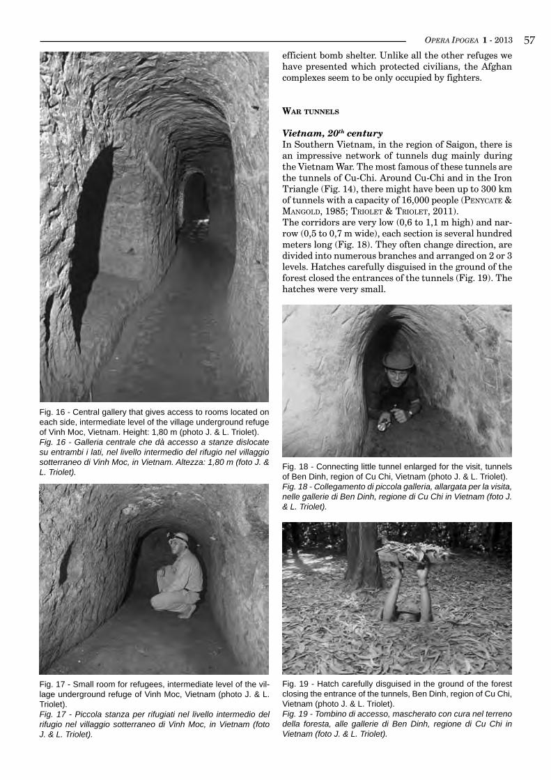
OPERA IPOGEA 1 - 2013 ��
Fig. 16 - Central gallery that gives access to rooms located on each side, intermediate level of the village underground refuge of Vinh Moc, Vietnam. Height: 1,80 m (photo J. & L. Triolet).Fig. 16 - Galleria centrale che dà accesso a stanze dislocate su entrambi i lati, nel livello intermedio del rifugio nel villaggio sotterraneo di Vinh Moc, in Vietnam. Altezza: 1,80 m (foto J. & L. Triolet).
Fig. 17 - Small room for refugees, intermediate level of the vil-lage underground refuge of Vinh Moc, Vietnam (photo J. & L. Triolet).Fig. 17 - Piccola stanza per rifugiati nel livello intermedio del rifugio nel villaggio sotterraneo di Vinh Moc, in Vietnam (foto J. & L. Triolet).
efficient bomb shelter. Unlike all the other refuges we have presented which protected civilians, the Afghan complexes seem to be only occupied by fighters.
War Tunnels
Vietnam, 20th centuryIn Southern Vietnam, in the region of Saigon, there is an impressive network of tunnels dug mainly during the Vietnam War. The most famous of these tunnels are the tunnels of Cu-Chi. Around Cu-Chi and in the Iron Triangle (Fig. 14), there might have been up to 300 km of tunnels with a capacity of 16,000 people (PenyCate & ManGold, 1985; triolet & triolet, 2011).The corridors are very low (0,6 to 1,1 m high) and nar-row (0,5 to 0,7 m wide), each section is several hundred meters long (Fig. 18). They often change direction, are divided into numerous branches and arranged on 2 or 3 levels. Hatches carefully disguised in the ground of the forest closed the entrances of the tunnels (Fig. 19). The hatches were very small.
Fig. 19 - Hatch carefully disguised in the ground of the forest closing the entrance of the tunnels, Ben Dinh, region of Cu Chi, Vietnam (photo J. & L. Triolet).Fig. 19 - Tombino di accesso, mascherato con cura nel terreno della foresta, alle gallerie di Ben Dinh, regione di Cu Chi in Vietnam (foto J. & L. Triolet).
Fig. 18 - Connecting little tunnel enlarged for the visit, tunnels of Ben Dinh, region of Cu Chi, Vietnam (photo J. & L. Triolet).Fig. 18 - Collegamento di piccola galleria, allargata per la visita, nelle gallerie di Ben Dinh, regione di Cu Chi in Vietnam (foto J. & L. Triolet).
OPERA IPOGEA 1 - 2013��
bibliography
bahManyar M., 2004, Afghanistan Cave Complexes 1979-2004, Mountain strongholds of the Mudjahideen, Taliban & Al Qaeda. Osprey Publishing, Oxford.
bertuCCi G., bixio r., traverso M., 1995, Le città sotterranee della Cappadocia. Erga edizioni, Genova, 140 pp.bixio r., Caloi v., Castellani v., suCChiarelli C., ruGGeri v., triolet J., triolet L., 2002, Cappadocia. Le città sotterra-
nee. Libreria dello Stato - Istituto Poligrafico e Zecca dello Stato, Roma, 319 pp.bixio r., de PasCale a. (eds), 2012, Cappadocia, Schede dei siti sotterranei / Records of the underground sites. British
Archaeological Reports International Series 2413, Oxford, 278 pp.deWerdt h.C., Paques G., WillMann F., 2009, Les Muches, souterrains-refuges de la Somme. Éditions Alan Sutton,
Saint-Cyr-sur-Loire, 176 pp.Fourdrin J.-P., 1979, Cinq souterrains du Ponthieu. Subterranea, n. 29, pp. 9-23.Grau l. W., Jalali A.A., 2001, The Campaign for the Caves: the Battles for Zhawar in the Soviet-Afghan War. Journal of
Slavic Military Studies, vol. 14, n. 3. [Online]: http://fmso.leavenworth.army.mil/documents/zhawar/zhawar.htm.PenyCate J., ManGold T., 1985, The tunnels of Cu Chi. Hodder & Stoughton, London.Petit B., 2001, Les «muches», une résistance rurale collective durant les XVIe et XVIIe siècles. Étude des souterrains
aménagés du canton de Villers-Bocage (Somme), Revue archéologique de Picardie, vol. 1, n. 1, pp. 73-125.triolet J., triolet l., 1993, Les villes souterraines de Cappadoce. Éditions DMI, Torcy, 114 pp.triolet J., triolet l., 1995, Les souterrains - Le monde des souterrains-refuges en France. Éditions Errance, Paris, 126
pp.triolet J., triolet l., 2002, Souterrains de Touraine, Blésois et Vendômois. Éditions Alan Sutton, Saint-Cyr-sur-Loire,
144 p.triolet J., triolet L., 2003, Souterrains du Poitou. Éditions Alan Sutton, Saint-Cyr-sur-Loire, 144 pp.triolet J., triolet L., 2011, La guerre souterraine. Éditions Perrin, Paris, 348 pp.xuân D., 2002, System of underground shelters for villages in Vinh Linh. Administration de la culture et de l’informa-
tion de Quang Tri, 33 pp.
Today in the tunnels of Ben Duoc, there is a hatch that is 30 cm long and 22 cm wide, and one can pass through the narrow opening! This tunnel network was connect-ed externally to trenches and firing positions. The long and narrow tunnels also lead to half-buried rooms in which Viet Cong spent most of the time.They were used as kitchens, sleeping-rooms, meeting-rooms, infirmaries or operating rooms. At the lower level, the corridors lead to underground rooms, smaller and safer, that were used as bomb shelters and con-tained food, weapons and ammunition storages.Thanks to the tunnels, the half-buried and under-ground rooms, Viet Cong fighters and Vietnamese villagers could escape aerial surveillance and protect themselves against repeated and destructive bombings. The predominance and the length of corridors show that they were also dug to allow Viet Cong fighters to escape mopping-up operations, to move secretly and to counter attack where they were not expected. The connections with trenches and firing positions confirm this function.The US Army understood the military importance of the tunnels, and in 1966 created special units to ex-plore and destroy the galleries: tunnel rats. On both sides, the fighting inside the tunnels was very fierce and very cruel. At the beginning of 1970, the tunnels were generally unusable by Viet Cong, but they helped to weaken the US Army. Because of the specific char-acteristics of Vietnamese underground networks and because of their direct involvement in the fight, they are different from underground refuges and we include them in a special category: war tunnels.
Lebanon, 21st centuryIn Southern Lebanon, the Hezbollah have dug tunnels
and bunkers several kilometers long, in the rock with carefully disguised entrances. In July 2006, the Israeli Army entered Southern Lebanon. Despite air power and the great technological superiority of Tsahal, well protected inside the cavities and moving secretly thanks to the tunnels, Hezbollah fighters effectively resisted the enemy. Israeli forces lost 120 soldiers and around 60 tanks.The galleries of South Lebanon seem to be a contem-porary variant of Vietnam war tunnels. Opened in May 2010 in Southern Lebanon, the Mleeta museum shows a portion of tunnels and underlines this Vietnamese influence.
Whatever the time and the place, underground refuges present the same development and the same organi-zation, including rooms for refugees connected by cor-ridors, vital facilities and defense systems. From the Middle Ages, underground refuges have been efficient fortresses because they were hidden and because it was easy to defend oneself inside the narrow corridors. During modern warfare they offer an additional advan-tage: the occupants escape aerial surveillance and are relatively well protected against bombing. War tunnels are quite different and it seems that they have emerged more recently. War tunnels also include rooms but the network of underground galleries is more important extending over a wider area. The tunnels have many entrances and are connected with trenches and firing positions.Thus using underground refuges or war tunnels, un-derground warfare is the weapon of the weak against the strong. Today this underground warfare is still ef-ficient in asymmetrical conflicts like those in Lebanon or Afghanistan.
OPERA IPOGEA 1 - 2013 ��
1 Centro Studi Sotterranei - Via Avio 6/7 - 16151 Genova (Italy); e-mail: [email protected] 2 Museo Archeologico del Finale, Istituto Internazionale di Studi Liguri sez. Finalese - Chiostri di Santa Caterina - 17024 Finale Ligure Borgo SV (Italy), e-mail: [email protected]
A new type of rock-cut works: the apiariesRoberto Bixio1, Andrea De Pascale1, 2
Abstract
Since many decades, the Centro Studi Sotterranei (Genoa, Italy) is conducting wide range investigations on artificial cavities. The objective is to identify and document the ancient underground structures that have historical or architectural significance built or excavated by man, studying their origin, evolution and pur-pose of utilization. Over the years, a large number of rock settlements has been explored, widely distributed on the Mediterranean Basin, from Italy to the Far East, and chronologically diversified as regards types: passage, hydric, military, mining, worship works and, of course, residential works and relating infrastruc-tures. Among the latter, researches are in progress about a particular type, the rupestrian apiaries, currently identified in three Mediterranean countries: central Turkey (Cappadocia), the island of Malta, and central-southern Italy. Waiting to extend in the near future investigations also to other areas, we propose here some considerations and comparisons between the structures so far documented.
key worDS: apiaries, classification, Malta, Turkey, Italy.
Riassunto
un nuovo tipo di struttura rupestre: gLi apiari
Da molti decenni il Centro Studi Sotterranei di Genova sta conducendo indagini ad ampio raggio sulle cavità artificiali. L’obiettivo è quello di individuare e documentare le antiche strutture scavate o costruite dall’uomo nel sottosuolo che abbiano valenza storica o architettonica, studiandone origine, evoluzione e destinazione d’uso. Nel corso degli anni è stato esplorato un numero rilevante di insediamenti rupestri, am-piamente distribuiti sul territorio (dall’Italia all’Estremo Oriente), differenziati cronologicamente e diversi-ficati nella tipologia: opere di transito, idriche, belliche, minerarie, di culto e, ovviamente, opere residenziali e relative infrastrutture. Tra queste ultime sono in corso ricerche su una particolare tipologia, gli apiari rupestri, attualmente individuati in tre paesi del bacino mediterraneo: la Turchia centrale (Cappadocia), l’isola di Malta, e l’Italia centro-meridionale. In attesa di estendere le indagini anche ad altre aree, si espon-gono in questa sede alcune considerazioni e confronti tra le strutture sino ad ora documentate, avanzando una proposta di classificazione tipologica per queste particolari opere destinate alla raccolta del miele e al controllo della sua produzione.La raccolta del miele da parte dell’uomo è nota e documentata a partire dalla preistoria tra diverse popola-zioni e culture in tutto il mondo, sia a scopo alimentare, sia per le sue proprietà curative. Da allora l’apicol-tura ha conosciuto una lunga, continua e diffusa evoluzione che da sistemi di allevamento individuali condotti in semplici tronchi cavi, peraltro, in qualche caso, ancora oggi utilizzati, si è organizzata in sistemi compositi denominati apiari.Si definisce apiario un insieme di alveari organizzato per l’allevamento delle api al fine della produzione del miele e di altri derivati (cera, propoli, pappa reale, polline). L’alveare è, a sua volta, composto da un conte-nitore (arnia) nel quale una famiglia di api (colonia o sciame) costruisce con la cera il proprio nido (favo) e produce il miele per nutrire le larve che nascono dalle uova deposte dalla regina.Nell’antichità, in alcune aree è attestata la collocazione degli alveari all’interno di alloggiamenti apposita-mente predisposti (housing apiaries, che gli apicoltori chiamano anche “apiari collettivi”), costruiti in mu-ratura o scavati nella roccia per contenere arnie di tipo più elementare (arnie villiche, costituite da cassette, cesti, cilindri fittili o altre forme) e fornire un riparo dagli agenti atmosferici.Nelle tavole qui presentate sono riportati vari tipi di apiari rupestri, rappresentati in modo schematico, sintetiz-zando le caratteristiche delle strutture apistiche finora documentate. Il risultato, per il momento, è stato quello di identificare tre categorie generali di apiari rupestri, gli ‘apiari a parete’ (categoria a), gli ‘apiari a camera aperta’ (categoria b) e gli ‘apiari a camera chiusa’ (categoria c), a loro volta suddivisi in più tipi. Va però tenuto presente
OPERA IPOGEA 1 - 2013�0
aPiaries
The collection of honey by humans, as well as the con-trol of its production, is well known and documented since prehistoric times among different populations and cultures around the world (Crane, 1999), both for food purpose and for its healing properties (Jones, 2009). A painting found at Çatalhöyük (near Konya, central Turkey), attributed to the late Neolithic, seems to suggest the transition from a simple collection phase to that of a first attempt of domestication, or at least, to control the bees (bortolin, 2008). Since then, the beekeeping knows a long, continuous and widespread evolution, from individual breeding systems handled inside simple hollow logs (in some cases, still used to-day), to organization in composite systems called apia-ries.We define apiary a set of beehives organised for the breeding of bees in order to product honey and other by-products (wax, propolis, royal jelly, pollen). The beehive, in turn, consists of a container (hive) in which a bee family (colony or swarm) builds with wax its nest (honeycomb) and produce honey to feed the larvae that are born from eggs laid by the queen. Apiaries may simply be groups of single beehives placed outdoors (open air apiaries) in localized plots of land, as it mainly happens since the middle 1800 following the invention of so-called rational hives used in modern beekeeping (zaPPi reCordati, 1980).In ancient times, in some areas it is attested the pla-cement of hives within specially prepared housings (housing apiaries, that beekeepers call “collective apia-ries”, too), built in masonry or excavated into the rock to contain the simplest type of hives (villager hives, consisting of boxes, baskets, fictile cylinders or other forms) and provide a shelter from the atmospheric agents. Sometimes, for example in Portugal, the beehi-ves were placed inside imposing structures built with high dry stone walls, usually circular or semicircular, to protect them from attacks by the animals (Guedes et al., 2002).It has also to be added that between Tenda and Briga,
and as far as Realdo (France-Italy), there are ‘more than 90 massive stone fences, with a characteristic and distinctive “horseshoe” shape, that were real “sanctua-ries” where from 50 to 100 “beehives” were kept, with a summer population that could vary from 1 to 3 million of bees for each enclosure’ (Masetti, 1996, p. 139).
In this article we will consider, according to the general research objectives of Centro Studi Sotterranei, only rock structures, excavated with various techniques in natural rock walls (rupestrian apiaries), thus excluding the masonry apiaries.
ruPesTrian aPiaries in caPPadocia
(cenTral Turkey)
The apiaries identified in Cappadocia, in the area between Ürgüp, Üçhisar, Göreme, Ortahisar and Çavuşin (district of Nevşehir), and in the valleys ofİhlara (district of Aksaray) and Soğanlı (district ofKayseri) are more than 50, catalogued by Gaby Roussel in 2006 and 2007. From the description (roussel, 2006, 2008), it appears that each of them, despite having its own peculiarities, has similar general features (apiaries with room fully excavated into the rock), with the two structures documented by Centro Studi Sotterranei in 2001 and 2003 (bixio et al., 2004, 2009; bixio & de PasCale, 2009, 2011).
Apiary A2, called NiketasThis structure is located at the head of the valley cal-led Kızıl Çukur (RedHollow), right tributary of theMeskendir-Zindanonu basin.It owes its name to the famous hermitage of Niketas the Stylite. His cell is attached to the Uzumlu Kilise, or Church of grapes, both excavated into the rock. Although the names of the ascetic and the donor, a certain Eustrate, army commander, are shown in an inscription, dating is controversial, probably between the sixth and ninth centuries (Jolivet-levy, 2001). Other spaces, called şaraphane, that means ‘cellar’,
che, in realtà, ogni installazione apistica possiede peculiarità proprie, non di rado associate ad opere in muratura.Dalle ricerche finora condotte risulta evidente che, nel panorama della apicoltura rupestre, non esisteva un modo univoco di alloggiare gli alveari: emerge, infatti, una variegata tipologia che va dalle strutture più ele-mentari (apiari a mensola della Puglia), a quelle più evolute (apiari a camera integrale della Cappadocia). In estrema sintesi, la differenza maggiore riscontrata tra gli apiari rupestri dell’Italia meridionale, da una parte, e quelli di Malta e della Cappadocia, dall’altra, consiste nel fatto che nei primi le arnie erano sempre disposte in modo da avere la bocca posteriore contro la parete di roccia. Tenendo presente che le operazioni inerenti alle ispezioni periodiche e al prelievo dei favi venivano di norma effettuate mediante apertura del-l’estremità opposta ai fori di volo e, qualche volta, della parte superiore, risulta evidente che le arnie doveva-no, quindi, ogni volta essere sfilate dal loro supporto, con notevole disturbo per le colonie di api. Dunque, il vantaggio degli apiari a camera chiusa (tipo c), presenti a Malta (camera murata) e in Cappadocia (camera integrale), deriva dal fatto che le arnie erano accessibili direttamente dalla bocca posteriore, senza che fosse necessario rimuoverle dal loro alloggiamento, evitando anche che l’apicoltore si interponesse davanti ai fori di volo, riducendo al minimo qualsiasi variazione nella routine degli alveari.
Parole chiave: apiari rupestri, classificazione, Malta, Turchia, Italia.
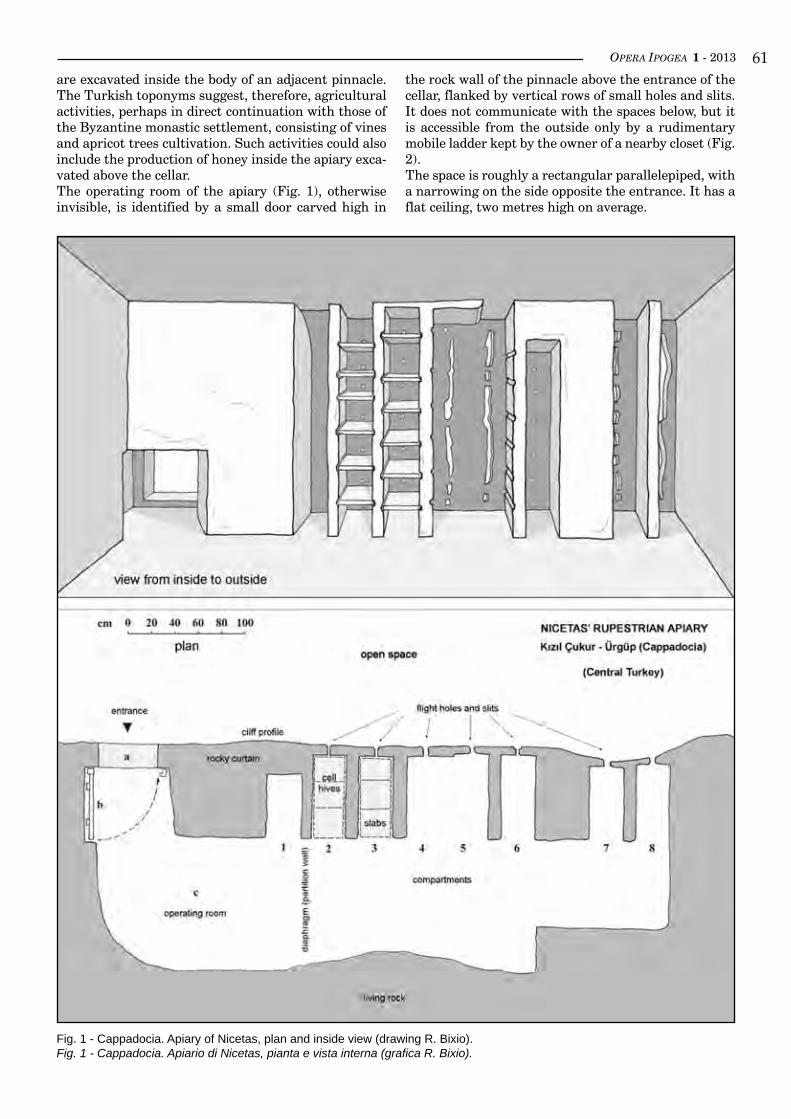
OPERA IPOGEA 1 - 2013 ��are excavated inside the body of an adjacent pinnacle. The Turkish toponyms suggest, therefore, agricultural activities, perhaps in direct continuation with those of the Byzantine monastic settlement, consisting of vines and apricot trees cultivation. Such activities could also include the production of honey inside the apiary exca-vated above the cellar.The operating room of the apiary (Fig. 1), otherwise invisible, is identified by a small door carved high in
the rock wall of the pinnacle above the entrance of the cellar, flanked by vertical rows of small holes and slits. It does not communicate with the spaces below, but it is accessible from the outside only by a rudimentary mobile ladder kept by the owner of a nearby closet (Fig. 2).The space is roughly a rectangular parallelepiped, with a narrowing on the side opposite the entrance. It has a flat ceiling, two metres high on average.
Fig. 1 - Cappadocia. Apiary of Nicetas, plan and inside view (drawing R. Bixio).Fig. 1 - Cappadocia. Apiario di Nicetas, pianta e vista interna (grafica R. Bixio).
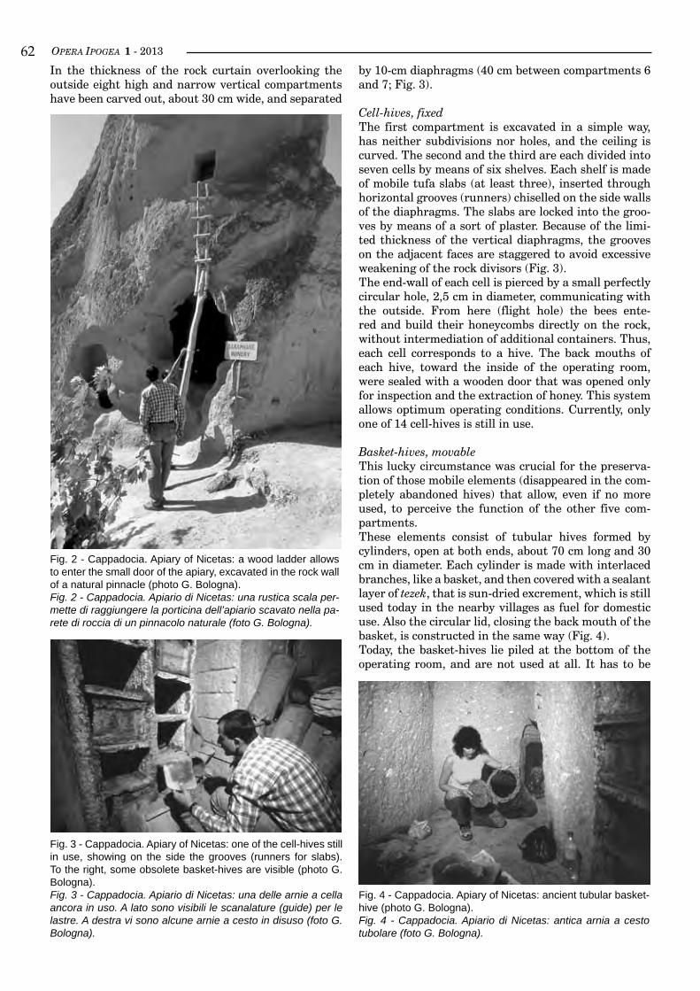
OPERA IPOGEA 1 - 2013��In the thickness of the rock curtain overlooking the outside eight high and narrow vertical compartments have been carved out, about 30 cm wide, and separated
by 10-cm diaphragms (40 cm between compartments 6 and 7; Fig. 3).
Cell-hives, fixedThe first compartment is excavated in a simple way, has neither subdivisions nor holes, and the ceiling is curved. The second and the third are each divided into seven cells by means of six shelves. Each shelf is made of mobile tufa slabs (at least three), inserted through horizontal grooves (runners) chiselled on the side walls of the diaphragms. The slabs are locked into the groo-ves by means of a sort of plaster. Because of the limi-ted thickness of the vertical diaphragms, the grooves on the adjacent faces are staggered to avoid excessive weakening of the rock divisors (Fig. 3).The end-wall of each cell is pierced by a small perfectly circular hole, 2,5 cm in diameter, communicating with the outside. From here (flight hole) the bees ente-red and build their honeycombs directly on the rock, without intermediation of additional containers. Thus, each cell corresponds to a hive. The back mouths of each hive, toward the inside of the operating room, were sealed with a wooden door that was opened only for inspection and the extraction of honey. This system allows optimum operating conditions. Currently, only one of 14 cell-hives is still in use.
Basket-hives, movableThis lucky circumstance was crucial for the preserva-tion of those mobile elements (disappeared in the com-pletely abandoned hives) that allow, even if no more used, to perceive the function of the other five com-partments.These elements consist of tubular hives formed by cylinders, open at both ends, about 70 cm long and 30 cm in diameter. Each cylinder is made with interlaced branches, like a basket, and then covered with a sealant layer of tezek, that is sun-dried excrement, which is still used today in the nearby villages as fuel for domestic use. Also the circular lid, closing the back mouth of the basket, is constructed in the same way (Fig. 4).Today, the basket-hives lie piled at the bottom of the operating room, and are not used at all. It has to be
Fig. 3 - Cappadocia. Apiary of Nicetas: one of the cell-hives still in use, showing on the side the grooves (runners for slabs). To the right, some obsolete basket-hives are visible (photo G. Bologna).Fig. 3 - Cappadocia. Apiario di Nicetas: una delle arnie a cella ancora in uso. A lato sono visibili le scanalature (guide) per le lastre. A destra vi sono alcune arnie a cesto in disuso (foto G. Bologna).
Fig. 2 - Cappadocia. Apiary of Nicetas: a wood ladder allows to enter the small door of the apiary, excavated in the rock wall of a natural pinnacle (photo G. Bologna).Fig. 2 - Cappadocia. Apiario di Nicetas: una rustica scala per-mette di raggiungere la porticina dell’apiario scavato nella pa-rete di roccia di un pinnacolo naturale (foto G. Bologna).
Fig. 4 - Cappadocia. Apiary of Nicetas: ancient tubular basket-hive (photo G. Bologna).Fig. 4 - Cappadocia. Apiario di Nicetas: antica arnia a cesto tubolare (foto G. Bologna).
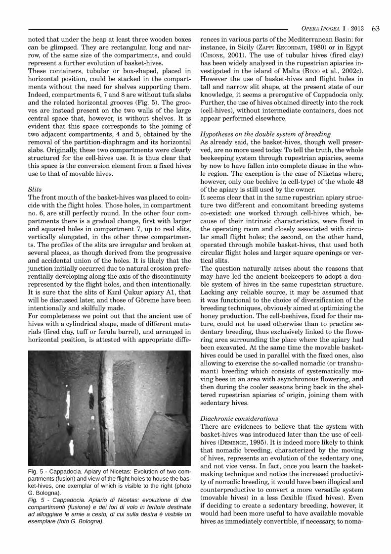
OPERA IPOGEA 1 - 2013 ��noted that under the heap at least three wooden boxes can be glimpsed. They are rectangular, long and nar-row, of the same size of the compartments, and could represent a further evolution of basket-hives.These containers, tubular or box-shaped, placed in horizontal position, could be stacked in the compart-ments without the need for shelves supporting them. Indeed, compartments 6, 7 and 8 are without tufa slabs and the related horizontal grooves (Fig. 5). The groo-ves are instead present on the two walls of the large central space that, however, is without shelves. It is evident that this space corresponds to the joining of two adjacent compartments, 4 and 5, obtained by the removal of the partition-diaphragm and its horizontal slabs. Originally, these two compartments were clearly structured for the cell-hives use. It is thus clear that this space is the conversion element from a fixed hives use to that of movable hives.
SlitsThe front mouth of the basket-hives was placed to coin-cide with the flight holes. Those holes, in compartment no. 6, are still perfectly round. In the other four com-partments there is a gradual change, first with larger and squared holes in compartment 7, up to real slits, vertically elongated, in the other three compartmen-ts. The profiles of the slits are irregular and broken at several places, as though derived from the progressive and accidental union of the holes. It is likely that the junction initially occurred due to natural erosion prefe-rentially developing along the axis of the discontinuity represented by the flight holes, and then intentionally. ItissurethattheslitsofKızılÇukurapiaryA1,thatwill be discussed later, and those of Göreme have been intentionally and skilfully made.For completeness we point out that the ancient use of hives with a cylindrical shape, made of different mate-rials (fired clay, tuff or ferula barrel), and arranged in horizontal position, is attested with appropriate diffe-
rences in various parts of the Mediterranean Basin: for instance, in Sicily (zaPPi reCordati, 1980) or in Egypt (Cirone, 2001). The use of tubular hives (fired clay) has been widely analysed in the rupestrian apiaries in-vestigated in the island of Malta (bixio et al., 2002c). However the use of basket-hives and flight holes in tall and narrow slit shape, at the present state of our knowledge, it seems a prerogative of Cappadocia only. Further, the use of hives obtained directly into the rock (cell-hives), without intermediate containers, does not appear performed elsewhere.
Hypotheses on the double system of breedingAs already said, the basket-hives, though well preser-ved, are no more used today. To tell the truth, the whole beekeeping system through rupestrian apiaries, seems by now to have fallen into complete disuse in the who-le region. The exception is the case of Niketas where, however, only one beehive (a cell-type) of the whole 48 of the apiary is still used by the owner. It seems clear that in the same rupestrian apiary struc-ture two different and concomitant breeding systems co-existed: one worked through cell-hives which, be-cause of their intrinsic characteristics, were fixed in the operating room and closely associated with circu-lar small flight holes; the second, on the other hand, operated through mobile basket-hives, that used both circular flight holes and larger square openings or ver-tical slits.The question naturally arises about the reasons that may have led the ancient beekeepers to adopt a dou-ble system of hives in the same rupestrian structure. Lacking any reliable source, it may be assumed that it was functional to the choice of diversification of the breeding techniques, obviously aimed at optimizing the honey production. The cell-beehives, fixed for their na-ture, could not be used otherwise than to practice se-dentary breeding, thus exclusively linked to the flowe-ring area surrounding the place where the apiary had been excavated. At the same time the movable basket-hives could be used in parallel with the fixed ones, also allowing to exercise the so-called nomadic (or transhu-mant) breeding which consists of systematically mo-ving bees in an area with asynchronous flowering, and then during the cooler seasons bring back in the shel-tered rupestrian apiaries of origin, joining them with sedentary hives.
Diachronic considerationsThere are evidences to believe that the system with basket-hives was introduced later than the use of cell-hives (deMenGe, 1995). It is indeed more likely to think that nomadic breeding, characterized by the moving of hives, represents an evolution of the sedentary one, and not vice versa. In fact, once you learn the basket-making technique and notice the increased productivi-ty of nomadic breeding, it would have been illogical and counterproductive to convert a more versatile system (movable hives) in a less flexible (fixed hives). Even if deciding to create a sedentary breeding, however, it would had been more useful to have available movable hives as immediately convertible, if necessary, to noma-
Fig. 5 - Cappadocia. Apiary of Nicetas: Evolution of two com-partments (fusion) and view of the flight holes to house the bas-ket-hives, one exemplar of which is visible to the right (photo G. Bologna).Fig. 5 - Cappadocia. Apiario di Nicetas: evoluzione di due compartimenti (fusione) e dei fori di volo in feritoie destinate ad alloggiare le arnie a cesto, di cui sulla destra è visibile un esemplare (foto G. Bologna).
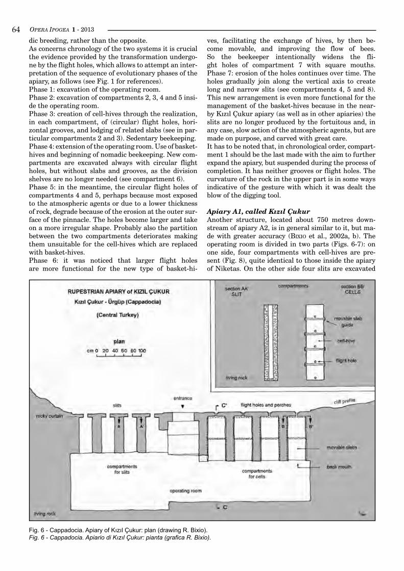
OPERA IPOGEA 1 - 2013��dic breeding, rather than the opposite.As concerns chronology of the two systems it is crucial the evidence provided by the transformation undergo-ne by the flight holes, which allows to attempt an inter-pretation of the sequence of evolutionary phases of the apiary, as follows (see Fig. 1 for references).Phase 1: excavation of the operating room.Phase 2: excavation of compartments 2, 3, 4 and 5 insi-de the operating room.Phase 3: creation of cell-hives through the realization, in each compartment, of (circular) flight holes, hori-zontal grooves, and lodging of related slabs (see in par-ticular compartments 2 and 3). Sedentary beekeeping.Phase 4: extension of the operating room. Use of basket-hives and beginning of nomadic beekeeping. New com-partments are excavated always with circular flight holes, but without slabs and grooves, as the division shelves are no longer needed (see compartment 6).Phase 5: in the meantime, the circular flight holes of compartments 4 and 5, perhaps because most exposed to the atmospheric agents or due to a lower thickness of rock, degrade because of the erosion at the outer sur-face of the pinnacle. The holes become larger and take on a more irregular shape. Probably also the partition between the two compartments deteriorates making them unsuitable for the cell-hives which are replaced with basket-hives.Phase 6: it was noticed that larger flight holes are more functional for the new type of basket-hi-
ves, facilitating the exchange of hives, by then be-come movable, and improving the flow of bees. So the beekeeper intentionally widens the fli-ght holes of compartment 7 with square mouths. Phase 7: erosion of the holes continues over time. The holes gradually join along the vertical axis to create long and narrow slits (see compartments 4, 5 and 8). This new arrangement is even more functional for the management of the basket-hives because in the near-byKızılÇukurapiary(aswellasinotherapiaries)theslits are no longer produced by the fortuitous and, in any case, slow action of the atmospheric agents, but are made on purpose, and carved with great care.It has to be noted that, in chronological order, compart-ment 1 should be the last made with the aim to further expand the apiary, but suspended during the process of completion. It has neither grooves or flight holes. The curvature of the rock in the upper part is in some ways indicative of the gesture with which it was dealt the blow of the digging tool.
Apiary A1, called Kızıl ÇukurAnother structure, located about 750 metres down-stream of apiary A2, is in general similar to it, but ma-de with greater accuracy (bixio et al., 2002a, b). The operating room is divided in two parts (Figs. 6-7): on one side, four compartments with cell-hives are pre-sent (Fig. 8), quite identical to those inside the apiary of Niketas. On the other side four slits are excavated
Fig. 6 - Cappadocia. Apiary of Kızıl Çukur: plan (drawing R. Bixio).Fig. 6 - Cappadocia. Apiario di Kızıl Çukur: pianta (grafica R. Bixio).
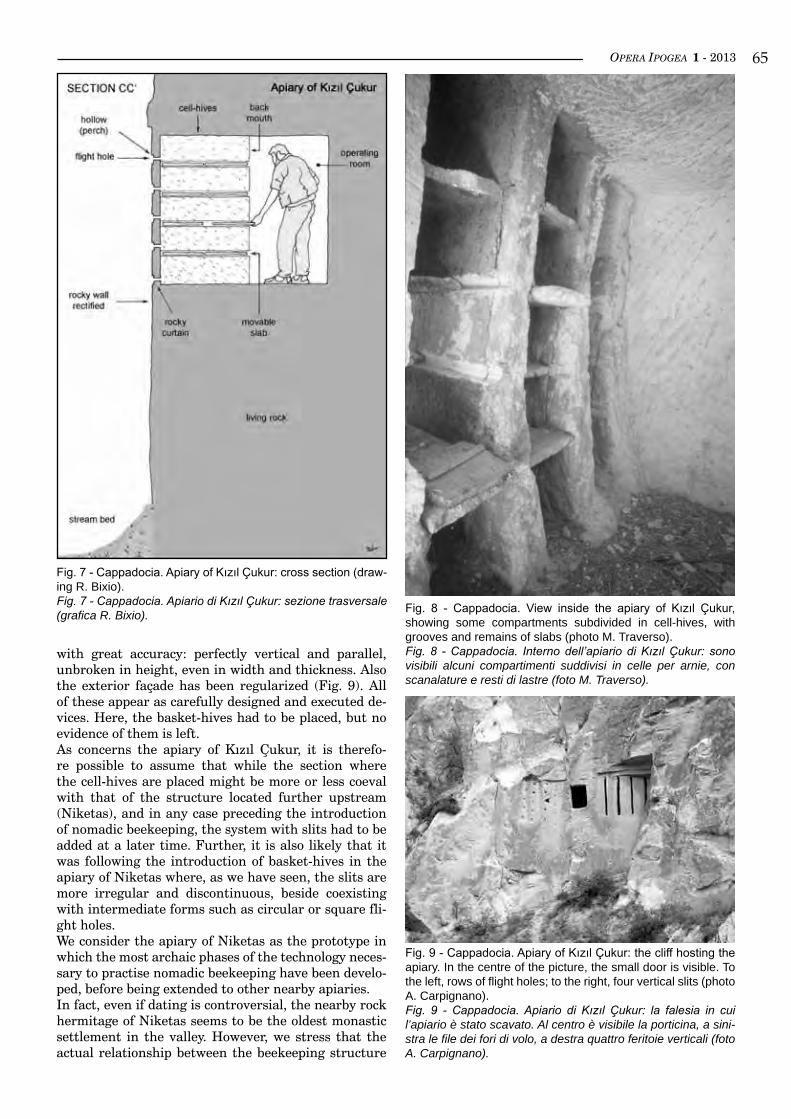
OPERA IPOGEA 1 - 2013 ��
with great accuracy: perfectly vertical and parallel, unbroken in height, even in width and thickness. Also the exterior façade has been regularized (Fig. 9). All of these appear as carefully designed and executed de-vices. Here, the basket-hives had to be placed, but no evidence of them is left.As concerns the apiary of Kızıl Çukur, it is therefo-re possible to assume that while the section where the cell-hives are placed might be more or less coeval with that of the structure located further upstream (Niketas), and in any case preceding the introduction of nomadic beekeeping, the system with slits had to be added at a later time. Further, it is also likely that it was following the introduction of basket-hives in the apiary of Niketas where, as we have seen, the slits are more irregular and discontinuous, beside coexisting with intermediate forms such as circular or square fli-ght holes.We consider the apiary of Niketas as the prototype in which the most archaic phases of the technology neces-sary to practise nomadic beekeeping have been develo-ped, before being extended to other nearby apiaries.In fact, even if dating is controversial, the nearby rock hermitage of Niketas seems to be the oldest monastic settlement in the valley. However, we stress that the actual relationship between the beekeeping structure
Fig. 7 - Cappadocia. Apiary of Kızıl Çukur: cross section (draw-ing R. Bixio).Fig. 7 - Cappadocia. Apiario di Kızıl Çukur: sezione trasversale (grafica R. Bixio). Fig. 8 - Cappadocia. View inside the apiary of Kızıl Çukur,
showing some compartments subdivided in cell-hives, with grooves and remains of slabs (photo M. Traverso).Fig. 8 - Cappadocia. Interno dell’apiario di Kızıl Çukur: sono visibili alcuni compartimenti suddivisi in celle per arnie, con scanalature e resti di lastre (foto M. Traverso).
Fig. 9 - Cappadocia. Apiary of Kızıl Çukur: the cliff hosting the apiary. In the centre of the picture, the small door is visible. To the left, rows of flight holes; to the right, four vertical slits (photo A. Carpignano).Fig. 9 - Cappadocia. Apiario di Kızıl Çukur: la falesia in cui l’apiario è stato scavato. Al centro è visibile la porticina, a sini-stra le file dei fori di volo, a destra quattro feritoie verticali (foto A. Carpignano).
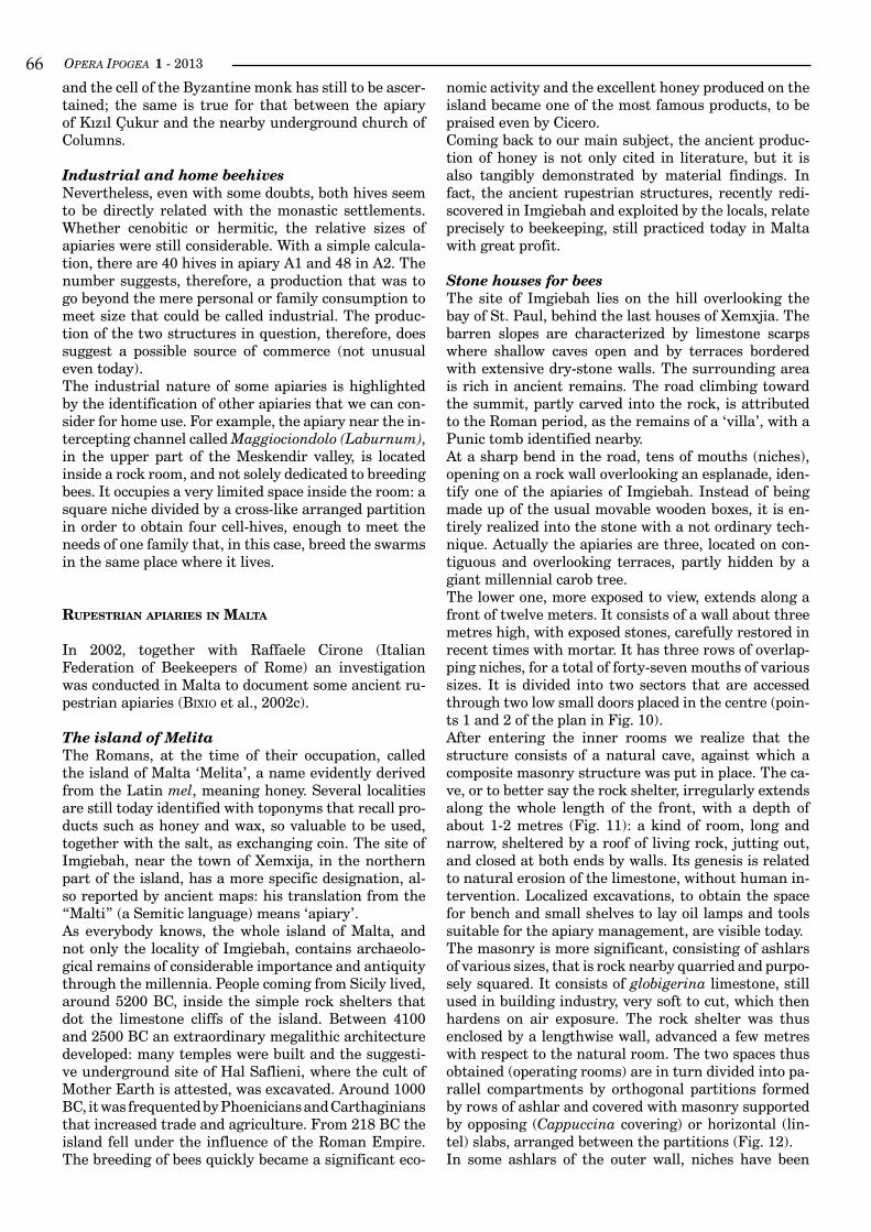
OPERA IPOGEA 1 - 2013��and the cell of the Byzantine monk has still to be ascer-tained; the same is true for that between the apiary ofKızılÇukurandthenearbyundergroundchurchofColumns.
Industrial and home beehivesNevertheless, even with some doubts, both hives seem to be directly related with the monastic settlements. Whether cenobitic or hermitic, the relative sizes of apiaries were still considerable. With a simple calcula-tion, there are 40 hives in apiary A1 and 48 in A2. The number suggests, therefore, a production that was to go beyond the mere personal or family consumption to meet size that could be called industrial. The produc-tion of the two structures in question, therefore, does suggest a possible source of commerce (not unusual even today).The industrial nature of some apiaries is highlighted by the identification of other apiaries that we can con-sider for home use. For example, the apiary near the in-tercepting channel called Maggiociondolo (Laburnum), in the upper part of the Meskendir valley, is located inside a rock room, and not solely dedicated to breeding bees. It occupies a very limited space inside the room: a square niche divided by a cross-like arranged partition in order to obtain four cell-hives, enough to meet the needs of one family that, in this case, breed the swarms in the same place where it lives.
ruPesTrian aPiaries in malTa
In 2002, together with Raffaele Cirone (Italian Federation of Beekeepers of Rome) an investigation was conducted in Malta to document some ancient ru-pestrian apiaries (bixio et al., 2002c).
The island of MelitaThe Romans, at the time of their occupation, called the island of Malta ‘Melita’, a name evidently derived from the Latin mel, meaning honey. Several localities are still today identified with toponyms that recall pro-ducts such as honey and wax, so valuable to be used, together with the salt, as exchanging coin. The site of Imgiebah, near the town of Xemxija, in the northern part of the island, has a more specific designation, al-so reported by ancient maps: his translation from the “Malti” (a Semitic language) means ‘apiary’.As everybody knows, the whole island of Malta, and not only the locality of Imgiebah, contains archaeolo-gical remains of considerable importance and antiquity through the millennia. People coming from Sicily lived, around 5200 BC, inside the simple rock shelters that dot the limestone cliffs of the island. Between 4100 and 2500 BC an extraordinary megalithic architecture developed: many temples were built and the suggesti-ve underground site of Hal Saflieni, where the cult of Mother Earth is attested, was excavated. Around 1000 BC, it was frequented by Phoenicians and Carthaginians that increased trade and agriculture. From 218 BC the island fell under the influence of the Roman Empire. The breeding of bees quickly became a significant eco-
nomic activity and the excellent honey produced on the island became one of the most famous products, to be praised even by Cicero.Coming back to our main subject, the ancient produc-tion of honey is not only cited in literature, but it is also tangibly demonstrated by material findings. In fact, the ancient rupestrian structures, recently redi-scovered in Imgiebah and exploited by the locals, relate precisely to beekeeping, still practiced today in Malta with great profit.
Stone houses for beesThe site of Imgiebah lies on the hill overlooking the bay of St. Paul, behind the last houses of Xemxjia. The barren slopes are characterized by limestone scarps where shallow caves open and by terraces bordered with extensive dry-stone walls. The surrounding area is rich in ancient remains. The road climbing toward the summit, partly carved into the rock, is attributed to the Roman period, as the remains of a ‘villa’, with a Punic tomb identified nearby.At a sharp bend in the road, tens of mouths (niches), opening on a rock wall overlooking an esplanade, iden-tify one of the apiaries of Imgiebah. Instead of being made up of the usual movable wooden boxes, it is en-tirely realized into the stone with a not ordinary tech-nique. Actually the apiaries are three, located on con-tiguous and overlooking terraces, partly hidden by a giant millennial carob tree.The lower one, more exposed to view, extends along a front of twelve meters. It consists of a wall about three metres high, with exposed stones, carefully restored in recent times with mortar. It has three rows of overlap-ping niches, for a total of forty-seven mouths of various sizes. It is divided into two sectors that are accessed through two low small doors placed in the centre (poin-ts 1 and 2 of the plan in Fig. 10).After entering the inner rooms we realize that the structure consists of a natural cave, against which a composite masonry structure was put in place. The ca-ve, or to better say the rock shelter, irregularly extends along the whole length of the front, with a depth of about 1-2 metres (Fig. 11): a kind of room, long and narrow, sheltered by a roof of living rock, jutting out, and closed at both ends by walls. Its genesis is related to natural erosion of the limestone, without human in-tervention. Localized excavations, to obtain the space for bench and small shelves to lay oil lamps and tools suitable for the apiary management, are visible today.The masonry is more significant, consisting of ashlars of various sizes, that is rock nearby quarried and purpo-sely squared. It consists of globigerina limestone, still used in building industry, very soft to cut, which then hardens on air exposure. The rock shelter was thus enclosed by a lengthwise wall, advanced a few metres with respect to the natural room. The two spaces thus obtained (operating rooms) are in turn divided into pa-rallel compartments by orthogonal partitions formed by rows of ashlar and covered with masonry supported by opposing (Cappuccina covering) or horizontal (lin-tel) slabs, arranged between the partitions (Fig. 12).In some ashlars of the outer wall, niches have been
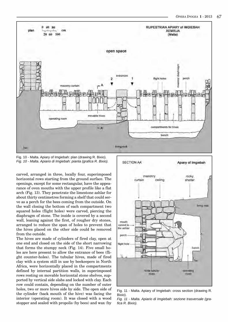
OPERA IPOGEA 1 - 2013 ��
carved, arranged in three, locally four, superimposed horizontal rows starting from the ground surface. The openings, except for some rectangular, have the appea-rance of oven mouths with the upper profile like a flat arch (Fig. 13). They penetrate the limestone ashlar for about thirty centimetres forming a shelf that could ser-ve as a perch for the bees coming from the outside. On the wall closing the bottom of each compartment two squared holes (flight holes) were carved, piercing the diaphragm of stone. The inside is covered by a second wall, leaning against the first, of rougher dry stones, arranged to reduce the span of holes to prevent that the hives placed on the other side could be removed from the outside.The hives are made of cylinders of fired clay, open at one end and closed on the side of the short narrowing that forms the stumpy neck (Fig. 14). Five small ho-les are here present to allow the entrance of bees (fli-ght counter-holes). The tubular hives, made of fired clay with a system still in use by beekeepers in North Africa, were horizontally placed in the compartments defined by internal partition walls, in superimposed rows resting on movable horizontal stone shelves, sup-ported by vertical side slabs and locked with clay. Each row could contain, depending on the number of outer holes, two or more hives side by side. The open side of the cylinder (back mouth of the hive) was facing the interior (operating room). It was closed with a wood stopper and sealed with propolis (by bees) and wax (by
Fig. 10 - Malta. Apiary of Imgiebah: plan (drawing R. Bixio).Fig. 10 - Malta. Apiario di Imgiebah: pianta (grafica R. Bixio).
Fig. 11 - Malta. Apiary of Imgiebah: cross section (drawing R. Bixio).Fig. 11 - Malta. Apiario di Imgiebah: sezione trasversale (gra-fica R. Bixio).
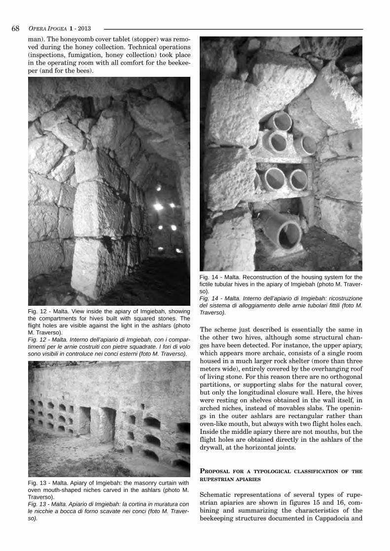
OPERA IPOGEA 1 - 2013��man). The honeycomb cover tablet (stopper) was remo-ved during the honey collection. Technical operations (inspections, fumigation, honey collection) took place in the operating room with all comfort for the beekee-per (and for the bees).
The scheme just described is essentially the same in the other two hives, although some structural chan-ges have been detected. For instance, the upper apiary, which appears more archaic, consists of a single room housed in a much larger rock shelter (more than three meters wide), entirely covered by the overhanging roof of living stone. For this reason there are no orthogonal partitions, or supporting slabs for the natural cover, but only the longitudinal closure wall. Here, the hives were resting on shelves obtained in the wall itself, in arched niches, instead of movables slabs. The openin-gs in the outer ashlars are rectangular rather than oven-like mouth, but always with two flight holes each. Inside the middle apiary there are not mouths, but the flight holes are obtained directly in the ashlars of the drywall, at the horizontal joints.
ProPosal for a TyPoloGical classificaTion of THe ruPesTrian aPiaries
Schematic representations of several types of rupe-strian apiaries are shown in figures 15 and 16, com-bining and summarizing the characteristics of the beekeeping structures documented in Cappadocia and
Fig. 12 - Malta. View inside the apiary of Imgiebah, showing the compartments for hives built with squared stones. The flight holes are visible against the light in the ashlars (photo M. Traverso).Fig. 12 - Malta. Interno dell’apiario di Imgiebah, con i compar-timenti per le arnie costruiti con pietre squadrate. I fori di volo sono visibili in controluce nei conci esterni (foto M. Traverso).
Fig. 13 - Malta. Apiary of Imgiebah: the masonry curtain with oven mouth-shaped niches carved in the ashlars (photo M. Traverso).Fig. 13 - Malta. Apiario di Imgiebah: la cortina in muratura con le nicchie a bocca di forno scavate nei conci (foto M. Traver-so).
Fig. 14 - Malta. Reconstruction of the housing system for the fictile tubular hives in the apiary of Imgiebah (photo M. Traver-so).Fig. 14 - Malta. Interno dell’apiario di Imgiebah: ricostruzione del sistema di alloggiamento delle arnie tubolari fittili (foto M. Traverso).
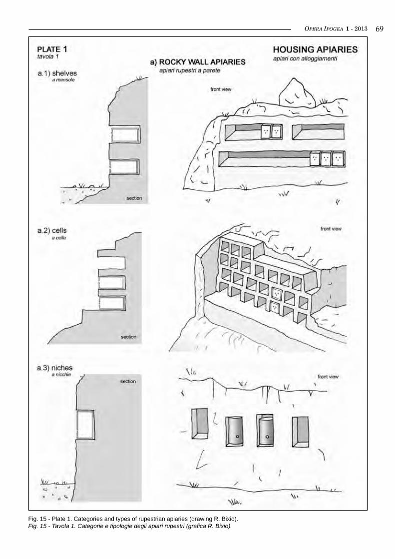
OPERA IPOGEA 1 - 2013 ��
Fig. 15 - Plate 1. Categories and types of rupestrian apiaries (drawing R. Bixio).Fig. 15 - Tavola 1. Categorie e tipologie degli apiari rupestri (grafica R. Bixio).
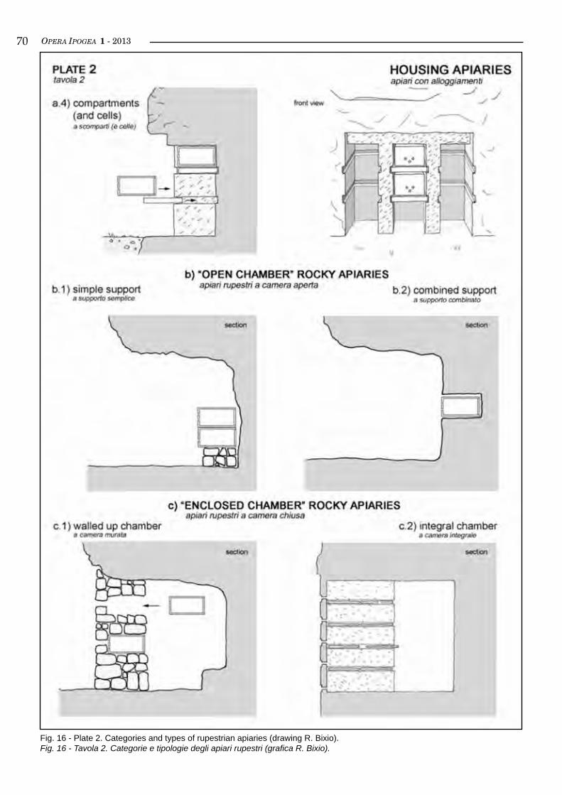
OPERA IPOGEA 1 - 2013�0
Fig. 16 - Plate 2. Categories and types of rupestrian apiaries (drawing R. Bixio).Fig. 16 - Tavola 2. Categorie e tipologie degli apiari rupestri (grafica R. Bixio).
OPERA IPOGEA 1 - 2013 ��Malta, described above, with those existing in the terri-tory of central-southern Italian regions (Latium, Sicily and, especially, Apulia, with particular reference to the evidence gathered by GreCo, 2001). The purpose of our attempt of synthesis is to identify general patterns in order to determine the types that may be used and in-tegrated with likely new varieties that might be found in future investigations. So far, three general catego-ries of rupestrian apiaries have been identified: the wall apiaries (category a), the open chamber apiaries (category b), and the enclosed chamber apiaries (cate-gory c); each of them is, in turn, split into several types. It has, however, to be reminded that every apiary has its own peculiarities, often associated with masonry.
Rock wall apiaries (category a)Rock wall apiaries are those structures in which the housing for the hives was obtained by excavating a mo-re or less vertical rock cliff. This cliff may be natural or obtained by rectifying the roughness of the rock. According to the shape of the structure, the wall apia-ries are classified in 4 types.
Shelves apiary (type a.1)It is the simplest housing type obtained by excavating in the rock a horizontal parallelepiped, with one of the long sides opening toward the outside. In this sort of shelf the hives are located side by side. The apiary can be formed by a single shelf, or by more shelves supe-rimposed and/or staggered.Examples in the following localities in the province of Taranto (Apulia): Fantiano and Malabarba (Grottaglie), Triglie (Crispiano), and S. Vito (Mottola).
Cells apiary (type a.2)A little more skill is required to realize an apiary with cells. These are obtained from excavation of single and/or overlapping parallelepipeds, similar to stacked bo-xes, separated by thin curtains obtained by saving the rock from excavation. Since it is clear that producing a continuous shelf (a.1 type), it would be easier and fa-ster than digging the same volume divided into several units, we assumed that housing in cells perhaps had the advantage of ensuring a greater thermal inertia to beehives.Examples in the following locality in the province of Taranto (Apulia): Crispiano.
Niches apiary (type a.3)We will call ‘niches’ the parallelepipeds carved out ver-tically, and shallow. Those in the province of Viterbo ha-ve height between 76 and 84 cm, width between 37 and 51 cm, and are deep between 38 and 43 cm (bortolin, 2008). The rupestrian apiary with niches is made up of individual cavities, excavated side by side on vertical natural rock walls. In each one, a single hive is verti-cally housed.In France there are examples of apiaries with niches obtained on regularized surfaces of old abandoned sto-ne quarries. The apiary at Ver dates back to 1793. From the description, the niche itself, closed by a small door, provided with flight holes and hinged on the rocky fra-
me, served as a hive, without the need of additional containers (Masetti, 2000). Next to this, a system of housing is briefly described, which seems more likely that of the rupestrian apiaries with integral chamber (see § “Enclosed chamber rock apiaries, category c”).The housing system with niches is considerably more common in masonry structures and is very popular in England (Crane, 1983).Examples in the following localities: Castello and Pian Castagno (Soriano nel Cimino, Viterbo province, Latium), Quarry of Estel (Vers, Gard, France).
Compartments and cells apiary (type a.4)This is a more complex structure of the previous ones: it consists of compartments, i.e. large vertical niches, adjacent to each other, separated by rock diaphragms obtained by saving the rock from excavation of a short antechamber slightly behind the vertical of the outer wall of the cliff. The diaphragms are also provided with parallel grooves (runners), carved on both sides, so that horizontal shelves can be inserted to divide into multi-ple overlapped cells each compartment for the housing of the hives.This type of installation, as well as representing a com-bination and evolution of types a.2 and a.3, can be con-sidered a form of transition from rock wall apiaries to those with open chamber (type b.2), with some simi-larities to those with integral enclosed chamber (type c.2).Examples in locality Masseria S. Angelo (Massafra), in the province of Taranto (Apulia).
Open chamber rock apiaries (category b)These are installations in which the housing for the hives are no more obtained in the external walls of the cliffs, but placed inside an underground void in the rock mass, with the side walls and its own rock coverage that define the upper part of the apiary, high at least as a man, or more. This space can consist of a pre-existing natural cavity, or may have been purposely excavated, in part or totally, by the beekeeper obtaining a service area for the management of the beehives.We define as ‘open chamber’ a cavity which entrance does not have any closure. Thus, it is completely open and the room is merely an additional shelter for the hives that are housed on various types of supports placed inside, leaning against the back or the sidewall. Open chamber apiaries can be distinguished into two types:
Simple support apiary (type b.1)The hives are simply laid, if necessary on superimposed rows, on the floor of the cavity, isolated by a simple planking or raised off the ground by a dry stone wall, without any additional infrastructure.Examples in the following localities: Madonna della Scala and Masseria S. Angelo (Massafra, Taranto pro-vince, Apulia), S. Lania (Lentini, Catania province, Sicily) (F. dell’aquila, personal communication).
Combined support apiary (type b.2)In this case, on the back wall of the cavity, or even on
OPERA IPOGEA 1 - 2013��the sidewalls, some houses for hives have been excavat-ed. Very similar to those described above as rock wall apiaries, they are usually horizontal shelves for hives.Examples in the following localities in the province of Taranto (Apulia): Masseria Torretta (Massafra), and Masseria Vicentino (Grottaglie).
A special case is described as type a.4 at Masseria S. Angelo (Massafra, Taranto province, Apulia), consist-ing of a shallow antechamber and more complex com-partments and cells. As already mentioned, it can be considered a form of transition.
Enclosed chamber rock apiaries (category c)In this case the cavities housing the hives are closed on all sides, with the entrance to the chamber allowed by a door.We decided to distinguish these apiaries in a specific category, rather than to aggregate them with the ‘open chamber’ in a generic category of ‘chamber apiaries’ tout court because this type of structure requires a sub-stantial change in the management of the beehives. In fact, the hives are no longer leaning against the walls of the cavity, but are inserted in the (masonry or rock) curtain wall closing the external front of the chamber (operating room). In this way the access is granted di-rectly to the rear part of the hives without having to re-move them from their housing, unlike to what happens in the wall or open chamber apiaries described above.Enclosed chamber apiaries are described on the mod-el of those documented in the island of Malta and in Cappadocia (see § “Rupestrian apiaries in Cappadocia, Central Turkey” and “Rupestrian apiaries in Malta”).
Walled up chamber apiary (type c.1)This is the case of the apiaries documented in Malta, in the site called Imgiebah (see § “Rupestrian apiaries in Malta”). Several apiaries are there present, variously structured, and essentially consisting of small natural rock shelters that have been closed on the outer side by dry-stone walls, obtaining one or more rooms (oper-ating rooms), with access through a small door. Some of the exterior ashlars were carved in order to obtain small niches (to be used as perches) and passing holes (flight holes). The hives were located in the back of the masonry curtain, matching the flight holes, supported by horizontal shelves inside vertical compartments di-vided by partitions, or by oven-like mouth cells, pur-posely built with dry stones. The back mouth of the hive, enclosed by a wooden lid, was thus accessible for the beekeeper, thus allowing him to proceed to normal operations without removing the container (tubular fictile beehives), minimizing the nuisance to the bees.
Integral chamber apiary (type c.2)In the valleys of Cappadocia, in central Turkey, more than fifty apiaries were identified (see § “Rupestrian apiaries in Cappadocia”), conceptually equivalent to those at Malta. The main difference lies in the fact that the Cappadocian structures do not exploit existing nat-ural cavities, but are fully obtained by the excavation of the tufa walls on cliffs and pinnacles, also closed on the
external side by a natural wall of rock, internally di-vided by vertical compartments, obtained by saving the rock from excavation. From the outside they are recog-nizable by a small door obtained into the wall, usually a few meters off the ground, lined with rows of holes (flight holes) and, in several cases, by vertical slits. These devices represent a peculiarity of Cappadocia: they have the same function as flight holes, but were destined for a different type of hive. In fact we have found that, inside the operating room, while fixed hives formed by slabs placed in horizontal grooves (runners) carved on the sides of the diaphragm and closed by wooden lids (cell hives) correspond to circular holes, superimposed rows of movable tubular hives, made of interlaced branches (basket hives), or box-shaped, were instead leaning against the slits.Further, it would be appropriate to investigate more thoroughly some of the apiaries called by Masetti ruches-placards, that is wall cupboard-hives, made in the rock wall of an abandoned quarry - already men-tioned in the § “Niches apiary (type a.3)” - which, from the short description, seem quite similar to the Cappadocian. In the quarry an inner chamber would be excavated, while the cells for the hives would be ob-tained in the thickness of the rock curtain. The hives would have the entrance for bees (flight holes) on the outside, and the taking mouth on the opposite side, in-side the chamber (Masetti, 2000).
discussion on ruPesTrian aPiaries
From the comparison of the brief descriptions above we can proceed to some considerations. First, it is clear that in the rupestrian beekeeping panorama there was not a unique way to house the hives but rather a wide assortment of types, ranging from the most basic struc-tures (shelves apiaries of Apulia) to the most evolved (integral chamber apiaries of Cappadocia), has to be observed.As already pointed out, the greater difference was found between the rupestrian apiaries in southern Italy, on one hand, and those at Malta and Cappadocia, on the other. In the case of Apulia, Latium and Sicily, in all types of considered housing, wall or chamber, the hives were always arranged with the back mouth against the rock wall. Bearing in mind that the operations related to periodic inspections and honeycombs taking were normally carried out through the opening of the end opposite to the flight holes and, sometimes, through the upper side (G. Pavanello, personal communica-tion), it is clear that the hives had to be removed every time from their support, with considerable disturbance to the colonies of bees. Thus, the main advantage of the enclosed chamber apiaries (type c), that we found only in Malta (walled up chamber) and Cappadocia (integral chamber), derives from the fact that the hives were accessible directly from the back mouth, without any need to remove them from their housing, also avoiding that the beekeeper interposes himself before the flight holes, minimizing any variation in the routine of the beehives.
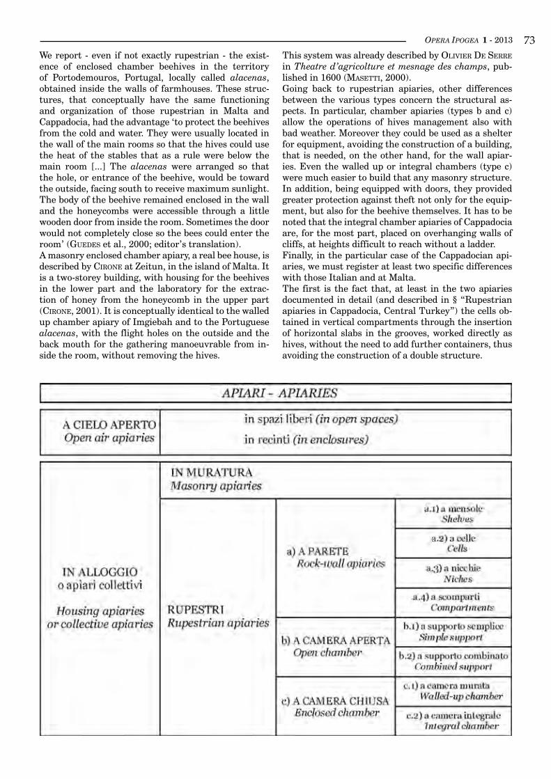
OPERA IPOGEA 1 - 2013 ��We report - even if not exactly rupestrian - the exist-ence of enclosed chamber beehives in the territory of Portodemouros, Portugal, locally called alacenas, obtained inside the walls of farmhouses. These struc-tures, that conceptually have the same functioning and organization of those rupestrian in Malta and Cappadocia, had the advantage ‘to protect the beehives from the cold and water. They were usually located in the wall of the main rooms so that the hives could use the heat of the stables that as a rule were below the main room [...] The alacenas were arranged so that the hole, or entrance of the beehive, would be toward the outside, facing south to receive maximum sunlight. The body of the beehive remained enclosed in the wall and the honeycombs were accessible through a little wooden door from inside the room. Sometimes the door would not completely close so the bees could enter the room’ (Guedes et al., 2000; editor’s translation).A masonry enclosed chamber apiary, a real bee house, is described by Cirone at Zeitun, in the island of Malta. It is a two-storey building, with housing for the beehives in the lower part and the laboratory for the extrac-tion of honey from the honeycomb in the upper part (Cirone, 2001). It is conceptually identical to the walled up chamber apiary of Imgiebah and to the Portuguese alacenas, with the flight holes on the outside and the back mouth for the gathering manoeuvrable from in-side the room, without removing the hives.
This system was already described by olivier de serre in Theatre d’agricolture et mesnage des champs, pub-lished in 1600 (Masetti, 2000).Going back to rupestrian apiaries, other differences between the various types concern the structural as-pects. In particular, chamber apiaries (types b and c) allow the operations of hives management also with bad weather. Moreover they could be used as a shelter for equipment, avoiding the construction of a building, that is needed, on the other hand, for the wall apiar-ies. Even the walled up or integral chambers (type c) were much easier to build that any masonry structure. In addition, being equipped with doors, they provided greater protection against theft not only for the equip-ment, but also for the beehive themselves. It has to be noted that the integral chamber apiaries of Cappadocia are, for the most part, placed on overhanging walls of cliffs, at heights difficult to reach without a ladder.Finally, in the particular case of the Cappadocian api-aries, we must register at least two specific differences with those Italian and at Malta.The first is the fact that, at least in the two apiaries documented in detail (and described in § “Rupestrian apiaries in Cappadocia, Central Turkey”) the cells ob-tained in vertical compartments through the insertion of horizontal slabs in the grooves, worked directly as hives, without the need to add further containers, thus avoiding the construction of a double structure.
OPERA IPOGEA 1 - 2013��
bibliography
bixio r., Castellani v., suCChiarelli C. (eds), 2002a, Cappadocia. Le città sotterranee. Istituto Poligrafico e Zecca dello Stato, Roma.
bixio r., dal Cin F., traverso M., 2002b, Cappadocia: un apiario rupestre. Opera Ipogea, 2/2002, Società Speleologica Italiana, Bologna, pp. 17-28.
bixio r., traverso M., Cirone R., 2002c, Apicoltura rupestre a Malta. Opera Ipogea, 3/2002, Società Speleologica Italia-na, Bologna, pp. 19-26.
bixio r., boloGna G., traverso M., 2004, Cappadocia 2003. Gli apiari rupestri dell’Altopiano Centrale Anatolico (Tur-chia). Opera Ipogea, 1/2004, Società Speleologica Italiana, Bologna, pp. 3-18.
bixio r., Caloi v., Castellani v., traverso M., 2009, Ani 2004: Indagini sugli insediamenti sotterranei / Surveys on the underground settlements. BAR International Series 1944, Oxford.
bixio r., de PasCale A., 2009, Archeologia delle cavità artificiali: le ricerche del Centro Studi Sotterranei di Genova in Turchia. Archeologia Medievale, n. XXXVI, pp. 129-154.
bixio r., de PasCale A. (eds.), 2011, Ahlat 2007: indagini preliminari sulle strutture rupestri - preliminary surveys on the underground structures. BAR International Series 2293, Oxford.
bortolin R., 2008, Archeologia del miele. SAP, Mantova.Cirone R., 2001, Un apiario in pietra riaffiora dopo 3000 anni... nel cuore del mare. Apitalia, n. 6/2001, Roma, pp.10-
17.Crane E., 1983, The Archaeology of Beekeeping. Duckworth, London.Crane E., 1999, The world history of beekeeping and honey hunting. Duckworth, London.deMenGe G., 1995, Pigeonniers et ruchers byzantins de Cappadoce. Archéologia, n. 311, Parigi, pp. 42-51.GreCo V.A., 2001, L’allevamento delle api nella storia del paesaggio agrario del tarantino. [Online]: www.perieghesis.
it/api.htm.Guedes H.I., Falda M.t., Pasini b., rossi e., laMeiro Ces M., 2002, Apicoltura, il sapore di una storia. Leader II project,
Corane.Jolivet-levy C., 2001, La Cappadoce médiévale. Zodiaque.Jones R., 2009, Honey and healing through the ages. Journal of ApiProduct and ApiMedical Science, n. 1 (1), pp. 2-5.Masetti L., 1996, Cenni sull’apicultura tradizionale nelle Alpi Liguri e Marittime. Intemelion - Quaderno di studi del-
l’Accademia di Cultura Intemelia, n. 2, pp. 139-144.Masetti L., 2000, La carrière de l’Estel. La santè de l’abeille, Magazine 180, 11-12/2000, pp. 358-361.roussel G., 2006, Découverte de vieux ruchers en Cappadoce. Cahiers d’Apistoria, n. 5 A, pp. 39-46.roussel G., 2008, Ruchers de Turquie. Cahiers d’Apistoria, n. 7 A, pp. 37-44.zaPPi reCordati A., 1980, Apicoltura. Reda, Roma.
acknowledgments
We kindly acknowledge Andrea Bixio for computer consulence and translation, Giorgio Pavanello, Franco Dell’Aquila and Gaby Roussel for the helpful information provided, and Simona Mordeglia for the bibliographic references.
This arrangement obviously had the disadvantage that the hives were not removable and, therefore, suitable only for sedentary beekeeping.It is our opinion that this handicap was overcome by the creation of compartments with vertical slits, which sev-eral Cappadocian apiaries have, associated with rows of flight holes, which were used to stack another type of hives, basket or box, movable, and, therefore, suitable for a possible form of nomadic beekeeping, maybe exer-cised simultaneously with the sedentary one.However, it is also possible that the evolution from
flight holes to slits, caused by natural erosion of the rock, has prompted the creation of movable containers (hives), to replace the fixed, coincident with the cells and become unusable, thus avoiding to leave the old apiary and to excavate a new one. This system would have then been extended throughout the region even during the construction of new compartments in case of expansion of the apiary, having also the advantage of making unnecessary to carve the grooves and hori-zontal slabs.
OPERA IPOGEA 1 - 2013 ��
Subterranea Britannica:Underground BritainMartin Dixon1
1 Subterranea Britannica; e-mail: [email protected]
Abstract
Man-made underground structures hold a special fascination for many historians, anthropologists and explorers. This article suggests some reasons for this fascination and goes on to describe many of the typolo-gies of underground sites in Great Britain. These include spaces constructed for religion, transportation, ex-traction, defence and concealment. Examples of each site type are given, along with current-day photographs of the structures. Sites described date from the Neolithic to the Nuclear age.Many stages of mankind’s development were only possible as a result of underground activity – whether this be the extraction of precious minerals/metals, the transportation of key resources or protection in times of war. Sites studied provide an important record and insight into these eras.Some sites described are well-known worldwide - such as the London Underground which celebrates its 150th anniversary in 2013. A number of sites are opened to the public by arrangement with the site owners and enthusiasts; others lie largely forgotten and are only accessible to dedicated explorers.The author, Martin Dixon, is Chairman of Subterranea Britannica: a UK based society which studies, visits and records man-made underground structures. Founded in 1974, Subterranea Britannica is a registered charity and has over 1,000 members. A guide to underground sites in the UK is available from www.subbrit.org.uk.
key worDS: artificial cavities, Subterranea Britannica, Great Britain.
Riassunto
subterranea britannica: La gran bretagna sotterranea
Le strutture sotterranee realizzate dall’uomo conservano un fascino particolare per molte categorie di studio-si, dagli storici, agli antropologi, sino ai semplici esploratori. Il presente articolo intende suggerire alcune delle motivazioni esistenti alla origine di tale fascino, e descrive brevemente alcune tra le tipologie di siti sotterranei esistenti in Gran Bretagna. Questi comprendono spazi realizzati per scopi religiosi, per trasporto, estrazione di materiali, a fini difensivi e come luoghi in cui nascondersi. Alcuni esempi per ciascuna tipo-logia sono illustrate, anche mediante fotografie attuali delle strutture. I siti trattati nell’articolo coprono un arco temporale che si estende dal Neolitico all’epoca nucleare.Molte fasi nello sviluppo storico dell’evoluzione della umanità sono state possibili solo come risultato di attività svolte nel mondo sotterraneo – siano queste consistite nella estrazione dal sottosuolo di materie pre-ziose (minerali o metalli), nel trasporto di risorse chiave o nella protezione in tempi di guerra. I siti studiati forniscono quindi elementi di prezioso interesse storico per la migliore comprensione delle epoche nel corso delle quali essi sono stati realizzati.Alcuni tra i luoghi descritti sono di fama mondiale – ad esempio, la Metropolitana di Londra, che celebrerà il 150° anniversario nel 2013. Molti di essi sono aperti al pubblico, grazie alla disponibilità dei proprietari o di appassionati; altri, invece, sono dimenticati e accessibili soltanto agli esploratori che se ne interessano. L’autore del presente articolo, Martin Dixon, è il Presidente di Subterranea Britannica, una società con base nel Regno Unito che si occupa dello studio, delle visite e della documentazione inerente le strutture sotter-ranee realizzate dall’uomo. Fondata nel 1974, Subterranea Britannica conta attualmente oltre 1000 soci. Ulteriori informazioni, e una guida per i siti sotterranei nel Regno Unito, sono disponibili al sito internet www.subbrit.org.uk.
Parole chiave: cavità artificiali, Gran Bretagna, Subterranea Britannica.
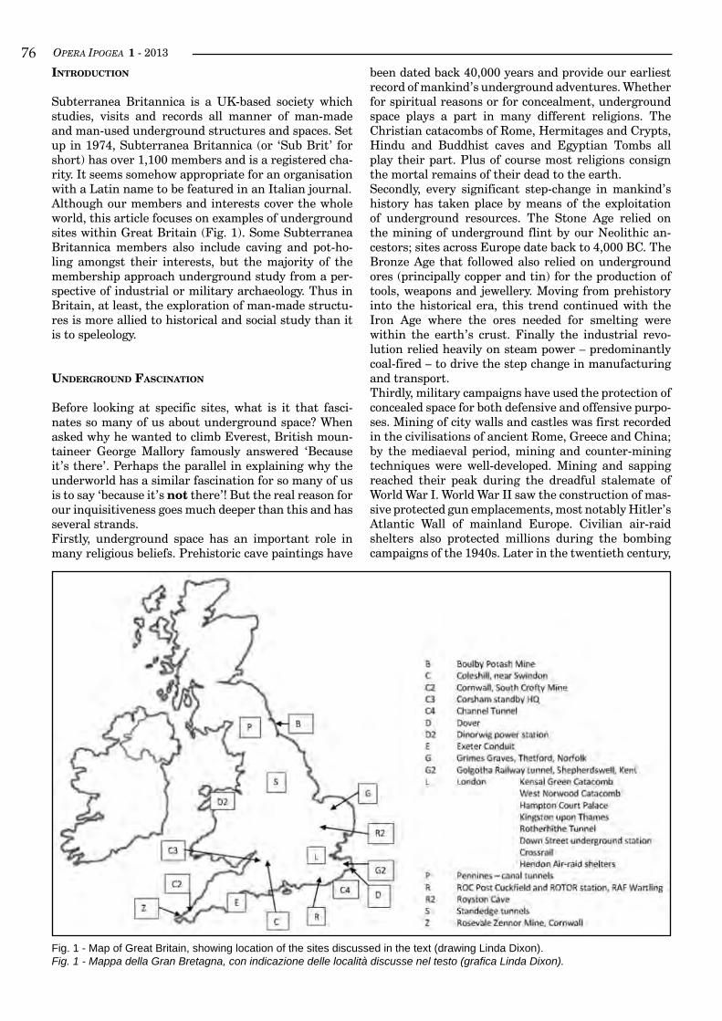
OPERA IPOGEA 1 - 2013��inTroducTion
Subterranea Britannica is a UK-based society which studies, visits and records all manner of man-made and man-used underground structures and spaces. Set up in 1974, Subterranea Britannica (or ‘Sub Brit’ for short) has over 1,100 members and is a registered cha-rity. It seems somehow appropriate for an organisation with a Latin name to be featured in an Italian journal. Although our members and interests cover the whole world, this article focuses on examples of underground sites within Great Britain (Fig. 1). Some Subterranea Britannica members also include caving and pot-ho-ling amongst their interests, but the majority of the membership approach underground study from a per-spective of industrial or military archaeology. Thus in Britain, at least, the exploration of man-made structu-res is more allied to historical and social study than it is to speleology.
underGround fascinaTion
Before looking at specific sites, what is it that fasci-nates so many of us about underground space? When asked why he wanted to climb Everest, British moun-taineer George Mallory famously answered ‘Because it’s there’. Perhaps the parallel in explaining why the underworld has a similar fascination for so many of us is to say ‘because it’s not there’! But the real reason for our inquisitiveness goes much deeper than this and has several strands.Firstly, underground space has an important role in many religious beliefs. Prehistoric cave paintings have
been dated back 40,000 years and provide our earliest record of mankind’s underground adventures. Whether for spiritual reasons or for concealment, underground space plays a part in many different religions. The Christian catacombs of Rome, Hermitages and Crypts, Hindu and Buddhist caves and Egyptian Tombs all play their part. Plus of course most religions consign the mortal remains of their dead to the earth.Secondly, every significant step-change in mankind’s history has taken place by means of the exploitation of underground resources. The Stone Age relied on the mining of underground flint by our Neolithic an-cestors; sites across Europe date back to 4,000 BC. The Bronze Age that followed also relied on underground ores (principally copper and tin) for the production of tools, weapons and jewellery. Moving from prehistory into the historical era, this trend continued with the Iron Age where the ores needed for smelting were within the earth’s crust. Finally the industrial revo-lution relied heavily on steam power – predominantly coal-fired – to drive the step change in manufacturing and transport.Thirdly, military campaigns have used the protection of concealed space for both defensive and offensive purpo-ses. Mining of city walls and castles was first recorded in the civilisations of ancient Rome, Greece and China; by the mediaeval period, mining and counter-mining techniques were well-developed. Mining and sapping reached their peak during the dreadful stalemate of World War I. World War II saw the construction of mas-sive protected gun emplacements, most notably Hitler’s Atlantic Wall of mainland Europe. Civilian air-raid shelters also protected millions during the bombing campaigns of the 1940s. Later in the twentieth century,
Fig. 1 - Map of Great Britain, showing location of the sites discussed in the text (drawing Linda Dixon).Fig. 1 - Mappa della Gran Bretagna, con indicazione delle località discusse nel testo (grafica Linda Dixon).
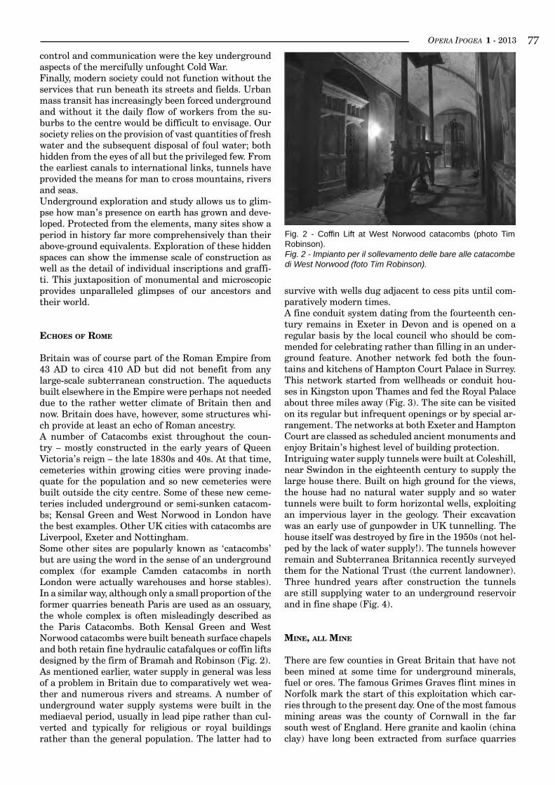
OPERA IPOGEA 1 - 2013 ��control and communication were the key underground aspects of the mercifully unfought Cold War.Finally, modern society could not function without the services that run beneath its streets and fields. Urban mass transit has increasingly been forced underground and without it the daily flow of workers from the su-burbs to the centre would be difficult to envisage. Our society relies on the provision of vast quantities of fresh water and the subsequent disposal of foul water; both hidden from the eyes of all but the privileged few. From the earliest canals to international links, tunnels have provided the means for man to cross mountains, rivers and seas.Underground exploration and study allows us to glim-pse how man’s presence on earth has grown and deve-loped. Protected from the elements, many sites show a period in history far more comprehensively than their above-ground equivalents. Exploration of these hidden spaces can show the immense scale of construction as well as the detail of individual inscriptions and graffi-ti. This juxtaposition of monumental and microscopic provides unparalleled glimpses of our ancestors and their world.
ecHoes of rome
Britain was of course part of the Roman Empire from 43 AD to circa 410 AD but did not benefit from any large-scale subterranean construction. The aqueducts built elsewhere in the Empire were perhaps not needed due to the rather wetter climate of Britain then and now. Britain does have, however, some structures whi-ch provide at least an echo of Roman ancestry.A number of Catacombs exist throughout the coun-try – mostly constructed in the early years of Queen Victoria’s reign – the late 1830s and 40s. At that time, cemeteries within growing cities were proving inade-quate for the population and so new cemeteries were built outside the city centre. Some of these new ceme-teries included underground or semi-sunken catacom-bs; Kensal Green and West Norwood in London have the best examples. Other UK cities with catacombs are Liverpool, Exeter and Nottingham.Some other sites are popularly known as ‘catacombs’ but are using the word in the sense of an underground complex (for example Camden catacombs in north London were actually warehouses and horse stables). In a similar way, although only a small proportion of the former quarries beneath Paris are used as an ossuary, the whole complex is often misleadingly described as the Paris Catacombs. Both Kensal Green and West Norwood catacombs were built beneath surface chapels and both retain fine hydraulic catafalques or coffin lifts designed by the firm of Bramah and Robinson (Fig. 2).As mentioned earlier, water supply in general was less of a problem in Britain due to comparatively wet wea-ther and numerous rivers and streams. A number of underground water supply systems were built in the mediaeval period, usually in lead pipe rather than cul-verted and typically for religious or royal buildings rather than the general population. The latter had to
survive with wells dug adjacent to cess pits until com-paratively modern times.A fine conduit system dating from the fourteenth cen-tury remains in Exeter in Devon and is opened on a regular basis by the local council who should be com-mended for celebrating rather than filling in an under-ground feature. Another network fed both the foun-tains and kitchens of Hampton Court Palace in Surrey. This network started from wellheads or conduit hou-ses in Kingston upon Thames and fed the Royal Palace about three miles away (Fig. 3). The site can be visited on its regular but infrequent openings or by special ar-rangement. The networks at both Exeter and Hampton Court are classed as scheduled ancient monuments and enjoy Britain’s highest level of building protection.Intriguing water supply tunnels were built at Coleshill, near Swindon in the eighteenth century to supply the large house there. Built on high ground for the views, the house had no natural water supply and so water tunnels were built to form horizontal wells, exploiting an impervious layer in the geology. Their excavation was an early use of gunpowder in UK tunnelling. The house itself was destroyed by fire in the 1950s (not hel-ped by the lack of water supply!). The tunnels however remain and Subterranea Britannica recently surveyed them for the National Trust (the current landowner). Three hundred years after construction the tunnels are still supplying water to an underground reservoir and in fine shape (Fig. 4).
mine, all mine
There are few counties in Great Britain that have not been mined at some time for underground minerals, fuel or ores. The famous Grimes Graves flint mines in Norfolk mark the start of this exploitation which car-ries through to the present day. One of the most famous mining areas was the county of Cornwall in the far south west of England. Here granite and kaolin (china clay) have long been extracted from surface quarries
Fig. 2 - Coffin Lift at West Norwood catacombs (photo Tim Robinson).Fig. 2 - Impianto per il sollevamento delle bare alle catacombe di West Norwood (foto Tim Robinson).
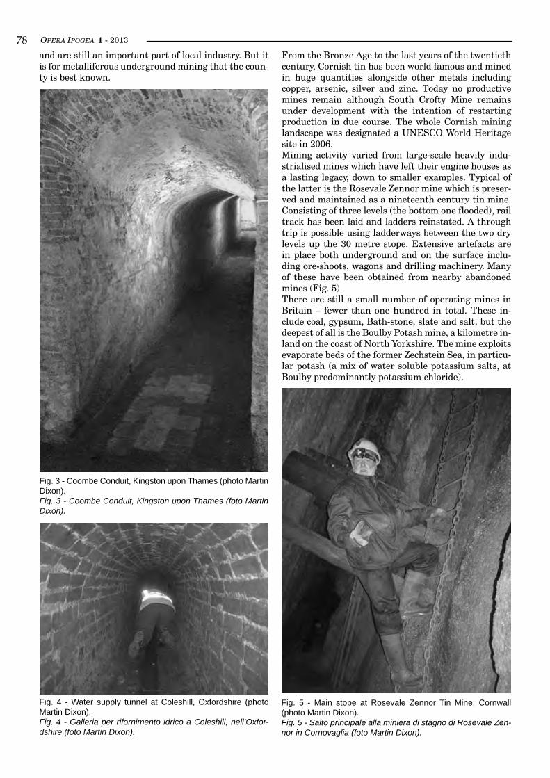
OPERA IPOGEA 1 - 2013��and are still an important part of local industry. But it is for metalliferous underground mining that the coun-ty is best known.
From the Bronze Age to the last years of the twentieth century, Cornish tin has been world famous and mined in huge quantities alongside other metals including copper, arsenic, silver and zinc. Today no productive mines remain although South Crofty Mine remains under development with the intention of restarting production in due course. The whole Cornish mining landscape was designated a UNESCO World Heritage site in 2006.Mining activity varied from large-scale heavily indu-strialised mines which have left their engine houses as a lasting legacy, down to smaller examples. Typical of the latter is the Rosevale Zennor mine which is preser-ved and maintained as a nineteenth century tin mine. Consisting of three levels (the bottom one flooded), rail track has been laid and ladders reinstated. A through trip is possible using ladderways between the two dry levels up the 30 metre stope. Extensive artefacts are in place both underground and on the surface inclu-ding ore-shoots, wagons and drilling machinery. Many of these have been obtained from nearby abandoned mines (Fig. 5).There are still a small number of operating mines in Britain – fewer than one hundred in total. These in-clude coal, gypsum, Bath-stone, slate and salt; but the deepest of all is the Boulby Potash mine, a kilometre in-land on the coast of North Yorkshire. The mine exploits evaporate beds of the former Zechstein Sea, in particu-lar potash (a mix of water soluble potassium salts, at Boulby predominantly potassium chloride).
Fig. 3 - Coombe Conduit, Kingston upon Thames (photo Martin Dixon).Fig. 3 - Coombe Conduit, Kingston upon Thames (foto Martin Dixon).
Fig. 4 - Water supply tunnel at Coleshill, Oxfordshire (photo Martin Dixon).Fig. 4 - Galleria per rifornimento idrico a Coleshill, nell’Oxfor-dshire (foto Martin Dixon).
Fig. 5 - Main stope at Rosevale Zennor Tin Mine, Cornwall (photo Martin Dixon).Fig. 5 - Salto principale alla miniera di stagno di Rosevale Zen-nor in Cornovaglia (foto Martin Dixon).
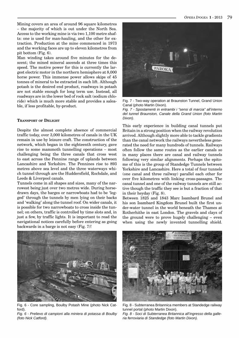
OPERA IPOGEA 1 - 2013 ��Mining covers an area of around 96 square kilometres – the majority of which is out under the North Sea. Access to the working mine is via two 1,100 metre shaf-ts: one is used for man-hauling, and the other for ex-traction. Production at the mine commenced in 1973 and the working faces are up to eleven kilometres from pit bottom (Fig. 6).Man winding takes around five minutes for the de-scent; the mined mineral ascends at three times this speed. The motive power for this is currently the lar-gest electric motor in the northern hemisphere at 8,000 horse power. This immense power allows skips of 45 tonnes of mineral to be extracted in each lift. Although potash is the desired end product, roadways in potash are not stable enough for long term use. Instead, all roadways are in the lower bed of rock salt (sodium chlo-ride) which is much more stable and provides a salea-ble, if less profitable, by-product.
TransPorT of deliGHT
Despite the almost complete absence of commercial traffic today, over 3,000 kilometres of canals in the UK remain in use by leisure craft. The construction of the network, which began in the eighteenth century, gave rise to some mammoth tunnelling operations – most challenging being the three canals that cross west to east across the Pennine range of uplands between Lancashire and Yorkshire. The Pennines rise to 893 metres above sea level and the three waterways whi-ch tunnel through are the Huddersfield, Rochdale, and Leeds & Liverpool canals.Tunnels come in all shapes and sizes, many of the nar-rowest being just over two metres wide. During horse-drawn days, the barges or narrowboats had to be ‘leg-ged’ through the tunnels by men lying on their backs and ‘walking’ along the tunnel roof. On wider canals, it is possible for two narrowboats to cross inside the tun-nel; on others, traffic is controlled by time slots and, in just a few, by traffic lights. It is important to read the navigational notices carefully before entering as going backwards in a barge is not easy (Fig. 7)!
This early experience in building canal tunnels put Britain in a strong position when the railway revolution arrived. Although slightly more able to tackle gradients than the canal network the railways nevertheless gene-rated the need for many hundreds of tunnels. Railways often follow the same routes as the earlier canals so in many places there are canal and railway tunnels following very similar alignments. Perhaps the epito-me of this is the group of Standedge Tunnels between Yorkshire and Lancashire. Here a total of four tunnels (one canal and three railway) parallel each other for over five kilometres with linking cross-passages. The canal tunnel and one of the railway tunnels are still ac-tive though the traffic they see is but a fraction of that in their heyday (Fig. 8).Between 1825 and 1843 Marc Isambard Brunel and his son Isambard Kingdom Brunel built the first un-der-water tunnel in the world beneath the Thames at Rotherhithe in east London. The gravels and clays of the ground were to prove hugely challenging – even when using the newly invented tunnelling shield.
Fig. 6 - Core sampling, Boulby Potash Mine (photo Nick Cat-ford).Fig. 6 - Prelievo di campioni alla miniera di potassa di Boulby (foto Nick Catford).
Fig. 7 - Two-way operation at Braunston Tunnel, Grand Union Canal (photo Martin Dixon).Fig. 7 - Spostamenti in entrambi i “sensi di marcia” all’interno del tunnel Braunston, Canale della Grand Union (foto Martin Dixon).
Fig. 8 - Subterranea Britannica members at Standedge railway tunnel portal (photo Martin Dixon).Fig. 8 - Soci di Subterranea Britannica all’ingresso della galle-ria ferroviaria di Standedge (foto Martin Dixon).
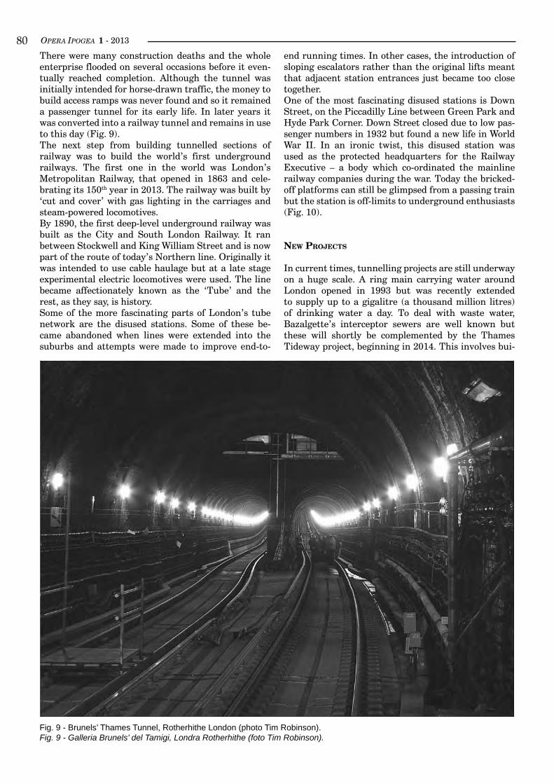
OPERA IPOGEA 1 - 2013�0There were many construction deaths and the whole enterprise flooded on several occasions before it even-tually reached completion. Although the tunnel was initially intended for horse-drawn traffic, the money to build access ramps was never found and so it remained a passenger tunnel for its early life. In later years it was converted into a railway tunnel and remains in use to this day (Fig. 9).The next step from building tunnelled sections of railway was to build the world’s first underground railways. The first one in the world was London’s Metropolitan Railway, that opened in 1863 and cele-brating its 150th year in 2013. The railway was built by ‘cut and cover’ with gas lighting in the carriages and steam-powered locomotives.By 1890, the first deep-level underground railway was built as the City and South London Railway. It ran between Stockwell and King William Street and is now part of the route of today’s Northern line. Originally it was intended to use cable haulage but at a late stage experimental electric locomotives were used. The line became affectionately known as the ‘Tube’ and the rest, as they say, is history.Some of the more fascinating parts of London’s tube network are the disused stations. Some of these be-came abandoned when lines were extended into the suburbs and attempts were made to improve end-to-
end running times. In other cases, the introduction of sloping escalators rather than the original lifts meant that adjacent station entrances just became too close together.One of the most fascinating disused stations is Down Street, on the Piccadilly Line between Green Park and Hyde Park Corner. Down Street closed due to low pas-senger numbers in 1932 but found a new life in World War II. In an ironic twist, this disused station was used as the protected headquarters for the Railway Executive – a body which co-ordinated the mainline railway companies during the war. Today the bricked-off platforms can still be glimpsed from a passing train but the station is off-limits to underground enthusiasts (Fig. 10).
neW ProjecTs
In current times, tunnelling projects are still underway on a huge scale. A ring main carrying water around London opened in 1993 but was recently extended to supply up to a gigalitre (a thousand million litres) of drinking water a day. To deal with waste water, Bazalgette’s interceptor sewers are well known but these will shortly be complemented by the Thames Tideway project, beginning in 2014. This involves bui-
Fig. 9 - Brunels’ Thames Tunnel, Rotherhithe London (photo Tim Robinson).Fig. 9 - Galleria Brunels’ del Tamigi, Londra Rotherhithe (foto Tim Robinson).
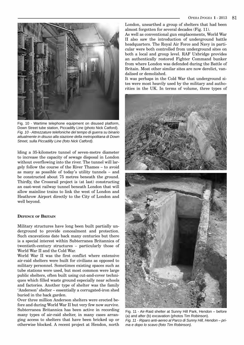
OPERA IPOGEA 1 - 2013 ��
Fig. 10 - Wartime telephone equipment on disused platform, Down Street tube station, Piccadilly Line (photo Nick Catford).Fig. 10 - Attrezzature telefoniche del tempo di guerra su binario attualmente in disuso alla stazione della metropolitana di Down Street, sulla Piccadilly Line (foto Nick Catford).
lding a 35-kilometre tunnel of seven-metre diameter to increase the capacity of sewage disposal in London without overflowing into the river. The tunnel will lar-gely follow the course of the River Thames – to avoid as many as possible of today’s utility tunnels – and be constructed about 75 metres beneath the ground. Thirdly, the Crossrail project is (at last) constructing an east-west railway tunnel beneath London that will allow mainline trains to link the west of London and Heathrow Airport directly to the City of London and well beyond.
defence of BriTain
Military structures have long been built partially un-derground to provide concealment and protection. Such excavations date back many centuries but there is a special interest within Subterranea Britannica of twentieth-century structures – particularly those of World War II and the Cold War.World War II was the first conflict where extensive air-raid shelters were built for civilians as opposed to military personnel. Sometimes existing spaces such as tube stations were used, but most common were large public shelters, often built using cut-and-cover techni-ques which filled waste ground especially near schools and factories. Another type of shelter was the family ‘Anderson’ shelter – essentially a corrugated-iron shed buried in the back garden.Over three million Anderson shelters were erected be-fore and during World War II but very few now survive. Subterranea Britannica has been active in recording many types of air-raid shelter, in many cases arran-ging access to shelters that have been bricked up or otherwise blocked. A recent project at Hendon, north
Fig. 11 - Air-Raid shelter at Sunny Hill Park, Hendon – before (a) and after (b) excavation (photos Tim Robinson).Fig. 11 - Riparo anti-aereo al Parco di Sunny Hill, Hendon – pri-ma e dopo lo scavo (foto Tim Robinson).
London, unearthed a group of shelters that had been almost forgotten for several decades (Fig. 11).As well as conventional gun emplacements, World War II also saw the introduction of underground battle headquarters. The Royal Air Force and Navy in parti-cular were both controlled from underground sites on both a local and group level. RAF Uxbridge provides an authentically restored Fighter Command bunker from where London was defended during the Battle of Britain. Most other similar sites are now derelict, van-dalised or demolished.It was perhaps in the Cold War that underground si-tes were most heavily used by the military and autho-rities in the UK. In terms of volume, three types of
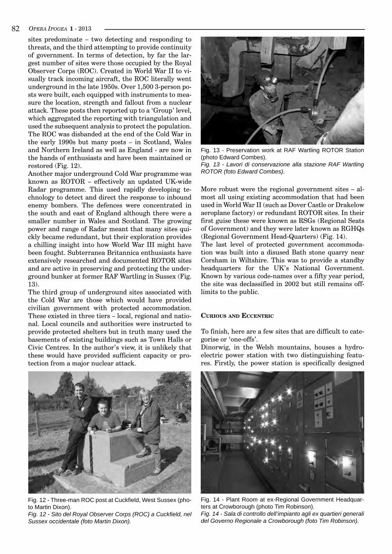
OPERA IPOGEA 1 - 2013��sites predominate – two detecting and responding to threats, and the third attempting to provide continuity of government. In terms of detection, by far the lar-gest number of sites were those occupied by the Royal Observer Corps (ROC). Created in World War II to vi-sually track incoming aircraft, the ROC literally went underground in the late 1950s. Over 1,500 3-person po-sts were built, each equipped with instruments to mea-sure the location, strength and fallout from a nuclear attack. These posts then reported up to a ‘Group’ level, which aggregated the reporting with triangulation and used the subsequent analysis to protect the population. The ROC was disbanded at the end of the Cold War in the early 1990s but many posts – in Scotland, Wales and Northern Ireland as well as England - are now in the hands of enthusiasts and have been maintained or restored (Fig. 12).Another major underground Cold War programme was known as ROTOR – effectively an updated UK-wide Radar programme. This used rapidly developing te-chnology to detect and direct the response to inbound enemy bombers. The defences were concentrated in the south and east of England although there were a smaller number in Wales and Scotland. The growing power and range of Radar meant that many sites qui-ckly became redundant, but their exploration provides a chilling insight into how World War III might have been fought. Subterranea Britannica enthusiasts have extensively researched and documented ROTOR sites and are active in preserving and protecting the under-ground bunker at former RAF Wartling in Sussex (Fig. 13).The third group of underground sites associated with the Cold War are those which would have provided civilian government with protected accommodation. These existed in three tiers – local, regional and natio-nal. Local councils and authorities were instructed to provide protected shelters but in truth many used the basements of existing buildings such as Town Halls or Civic Centres. In the author’s view, it is unlikely that these would have provided sufficient capacity or pro-tection from a major nuclear attack.
More robust were the regional government sites – al-most all using existing accommodation that had been used in World War II (such as Dover Castle or Drakelow aeroplane factory) or redundant ROTOR sites. In their first guise these were known as RSGs (Regional Seats of Government) and they were later known as RGHQs (Regional Government Head-Quarters) (Fig. 14).The last level of protected government accommoda-tion was built into a disused Bath stone quarry near Corsham in Wiltshire. This was to provide a standby headquarters for the UK’s National Government. Known by various code-names over a fifty year period, the site was declassified in 2002 but still remains off-limits to the public.
curious and eccenTric
To finish, here are a few sites that are difficult to cate-gorise or ‘one-offs’.Dinorwig, in the Welsh mountains, houses a hydro-electric power station with two distinguishing featu-res. Firstly, the power station is specifically designed
Fig. 13 - Preservation work at RAF Wartling ROTOR Station (photo Edward Combes).Fig. 13 - Lavori di conservazione alla stazione RAF Wartling ROTOR (foto Edward Combes).
Fig. 14 - Plant Room at ex-Regional Government Headquar-ters at Crowborough (photo Tim Robinson).Fig. 14 - Sala di controllo dell’impianto agli ex quartieri generali del Governo Regionale a Crowborough (foto Tim Robinson).
Fig. 12 - Three-man ROC post at Cuckfield, West Sussex (pho-to Martin Dixon).Fig. 12 - Sito del Royal Observer Corps (ROC) a Cuckfield, nel Sussex occidentale (foto Martin Dixon).
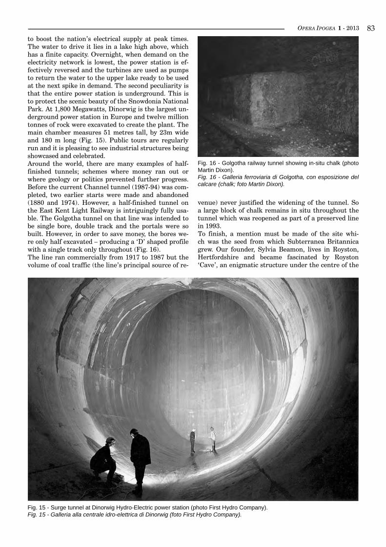
OPERA IPOGEA 1 - 2013 ��
Fig. 15 - Surge tunnel at Dinorwig Hydro-Electric power station (photo First Hydro Company).Fig. 15 - Galleria alla centrale idro-elettrica di Dinorwig (foto First Hydro Company).
Fig. 16 - Golgotha railway tunnel showing in-situ chalk (photo Martin Dixon).Fig. 16 - Galleria ferroviaria di Golgotha, con esposizione del calcare (chalk; foto Martin Dixon).
to boost the nation’s electrical supply at peak times. The water to drive it lies in a lake high above, which has a finite capacity. Overnight, when demand on the electricity network is lowest, the power station is ef-fectively reversed and the turbines are used as pumps to return the water to the upper lake ready to be used at the next spike in demand. The second peculiarity is that the entire power station is underground. This is to protect the scenic beauty of the Snowdonia National Park. At 1,800 Megawatts, Dinorwig is the largest un-derground power station in Europe and twelve million tonnes of rock were excavated to create the plant. The main chamber measures 51 metres tall, by 23m wide and 180 m long (Fig. 15). Public tours are regularly run and it is pleasing to see industrial structures being showcased and celebrated.Around the world, there are many examples of half-finished tunnels; schemes where money ran out or where geology or politics prevented further progress. Before the current Channel tunnel (1987-94) was com-pleted, two earlier starts were made and abandoned (1880 and 1974). However, a half-finished tunnel on the East Kent Light Railway is intriguingly fully usa-ble. The Golgotha tunnel on that line was intended to be single bore, double track and the portals were so built. However, in order to save money, the bores we-re only half excavated – producing a ‘D’ shaped profile with a single track only throughout (Fig. 16).The line ran commercially from 1917 to 1987 but the volume of coal traffic (the line’s principal source of re-
venue) never justified the widening of the tunnel. So a large block of chalk remains in situ throughout the tunnel which was reopened as part of a preserved line in 1993.To finish, a mention must be made of the site whi-ch was the seed from which Subterranea Britannica grew. Our founder, Sylvia Beamon, lives in Royston, Hertfordshire and became fascinated by Royston ‘Cave’, an enigmatic structure under the centre of the
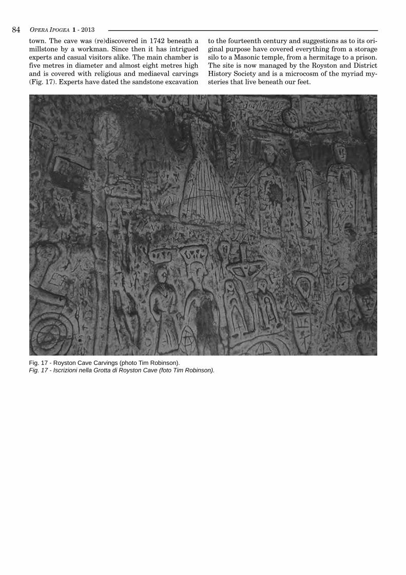
OPERA IPOGEA 1 - 2013��
Fig. 17 - Royston Cave Carvings (photo Tim Robinson).Fig. 17 - Iscrizioni nella Grotta di Royston Cave (foto Tim Robinson).
town. The cave was (re)discovered in 1742 beneath a millstone by a workman. Since then it has intrigued experts and casual visitors alike. The main chamber is five metres in diameter and almost eight metres high and is covered with religious and mediaeval carvings (Fig. 17). Experts have dated the sandstone excavation
to the fourteenth century and suggestions as to its ori-ginal purpose have covered everything from a storage silo to a Masonic temple, from a hermitage to a prison. The site is now managed by the Royston and District History Society and is a microcosm of the myriad my-steries that live beneath our feet.
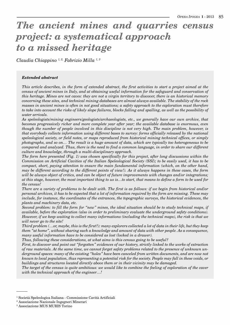
OPERA IPOGEA 1 - 2013 ��
The ancient mines and quarries census project: a systematical approachto a missed heritageClaudia Chiappino 1, 2, Fabrizio Milla 1, 3
1 Società Speleologica Italiana - Commissione Cavità Artificiali2 Associazione Nazionale Ingegneri Minerari3 Associazione MUS MURIS Torino
Extended abstract
This article describes, in the form of extended abstract, the first activities to start a project aimed at the census of ancient mines in Italy, and at obtaining useful information for the safeguard and conservation of this heritage. Mines are not caves: they are not a virgin territory to discover, there is an historical memory concerning these sites, and technical mining databases are almost always available. The stability of the rock masses in ancient mines is often in not good situations; a safety approach to the exploration must therefore to take into account the risks of likely slope failures, blocks falling and spalling, as well as the possibility of water arrivals. As speleologists/mining engineers/geologists/archaeologists, etc., we generally have our own archive, that becomes progressively richer and more complete year after year; the available database is enormous, even though the number of people involved in this discipline is not very high. The main problem, however, is that everybody collects information using different bases to survey: forms officially released by the national speleological society, or field notes, or maps reproduced from historical mining technical offices, or simply photographs, and so on… The result is a huge amount of data, which are typically too heterogeneous to be compared and analyzed. Thus, there is the need to find a common language, in order to share our different culture and knowledge, through a multi-disciplinary approach.The form here presented (Fig. 1) was chosen specifically for this project, after long discussions within the Commission on Artificial Cavities of the Italian Speleological Society (SSI); to be easily used, it has to be compact, short, paying attention to ensure the main fundamental information (which, on the other hand, may be different according to the different points of view!). As it always happens in these cases, the form will be always object of critics, and can be object of future improvements with changes and/or integrations; at this stage, however, the most important thing to us is…to start, that means to define a form to be used for the census!There are a variety of problems to be dealt with. The first is as follows: if we begin from historical and/or personal archives, it has to be expected that a lot of information required by the form are missing. These may include, for instance, the coordinates of the entrances, the topographic surveys, the historical evidences, the plants and machinery data, etc.Second problem: to fill the form for “new” mines, the ideal situation should be to study technical maps, if available, before the exploration (also in order to preliminary evaluate the underground safety conditions). However, if we keep waiting to collect many informations (including the technical maps), the risk is that we will never go to the site!Third problem (…or, maybe, this is the first?): many explorers collected a lot of data in their life, but they keep them “at home”, without sharing such a knowledge and amount of data with other people. As a consequence, many useful information have to be considered as lost (locked in a drawer). Thus, following these considerations, at what aims is this census going to be useful?First, to discover and point out “forgotten” evidences of our history, strictly linked to the works of extraction of raw materials. At the same time, we cannot forget safety problems related to the presence of unknown un-derground spaces: many of the existing “holes” have been canceled from written documents, and are now not known to local population, thus representing a potential risk for the society. People may fall in these voids, or buildings and structures located directly above them or in their vicinity may be damaged.The target of the census is quite ambitious: we would like to combine the feeling of exploration of the caver with the technical approach of the engineer…!
OPERA IPOGEA 1 - 2013��
The first period of survey and compilation of the form will naturally point out the main criticalities and pro-blems; these will be carefully examined and, if necessary, some changes will be introduced in order to correct them, and to reach the best results. The first test of the project will be carried out in the Piedmont region (nor-th-western Italy); then, the target is to extend the census to the other regions, and cover the whole country.The pilot-project in Piedmont will also provide indications about the methodology, and will result in the preliminary elements to create the most useful approach; for example, starting from the consolidated existing databases (regional register of artificial cavities, personal data, bibliography, etc.), one of the crucial elemen-ts is to exactly locate the entrance to the site. Following this first task, and after the necessary identification and inspection of the site, analyses of the archives and bibliography will be performed.Last but not least, since in Italy exploration of old mines is forbidden, it is necessary to face the legal and ad-ministrative problems, in terms of permission to access the sites. At the time we write this extended abstract, a Technical Committee has been established for this task in Lombardy region.
key worDS: mines, census, cultural heritage, Piedmont, Italy.
Riassunto esteso
iL censimento deLLe antiche miniere e cave: un approccio sistematico per La saLvaguardia di un patri-monio perduto
Un punto di partenza fondamentale per un corretto approccio a questo lavoro è aver sempre presente che le miniere non sono grotte: non si tratta pertanto di scoprire cavità, bensì al massimo di “ri-scoprirle”, dopo anni, decenni o secoli di abbandono fisico o storico-culturale. È quindi fondamentale partire dall’esistenza di una memoria storica (archivi tecnici, documentazione amministrativa legata al periodo di esercizio, cro-nache connesse alle questioni sociali…) quasi sempre disponibile.Gli scavi minerari portano in sé un rischio intrinseco relativo a possibilità di crolli, inondazioni e dissesti vari; l’approccio a tali luoghi deve pertanto tener conto della sicurezza dell’ambiente ipogeo e delle conse-guenti cautele da adottare.Le figure coinvolte nella ricerca e documentazione dei vecchi siti minerari sono molteplici (tra questi, spe-leologi, ingegneri minerari, geologi, e archeologi) e caratterizzate di frequente da un diverso approccio al problema.Potenzialmente, ogni esperto dell’argomento possiede un suo “archivio” (predisposto sulla base di deter-minati criteri di raccolta ed utilizzo dei dati) che si arricchisce anno dopo anno, quindi la massa di dati complessivamente disponibile sulla materia è enorme. Essi, date le notevoli differenze culturali, sono anche organizzati in maniera differente e possono avere come base di rilevamento schede ufficiali proposte dalle organizzazioni speleologiche nazionali (nel caso italiano, la SSI), rilievi e note di campagna, le planimetrie provenienti dall’archivio del Corpo delle Miniere, ecc… In poche parole, i dati disponibili non sono omogenei e vi è la necessità di trovare un linguaggio comune.Scopo del censimento in questione è far emergere le testimonianze della nostra storia, che mai potrà prescin-dere dall’estrazione delle materie prime, sebbene le scelte politiche più o meno recenti abbiano condannato a morte l’attività estrattiva, nella maggioranza dei casi in modo irreversibile. Vanno inoltre considerate anche le immancabili ricadute dello studio in termini di sicurezza; di molte cavità si è persa nel tempo l’ubicazio-ne, oltre alle principali informazioni riguardanti lo sviluppo degli scavi in sotterraneo, anche quando di notevole estensione.Innegabile che questa situazione possa costituire un potenziale (e comprovato) rischio, non soltanto per la ca-duta di persone nelle cavità non segnalate, ma anche per la possibilità di crolli che possano compromettere le strutture antropiche sovrastanti. La storia mineraria insegna: molte tragedie con pesante bilancio in vittime sono state causate da franamenti di strutture sotterranee, o da improvvise venute d’acqua.Questo approccio al problema vorrebbe unire il metodo esplorativo proprio dello speleologo a quello tecnico più tipicamente ingegneristico. Dopo un primo periodo di test sulle miniere piemontesi, si esamineranno le problematiche emerse al fine di correggere il tiro, per arrivare al miglior risultato. Dopo l’esperimento pie-montese, l’obiettivo è estendere il censimento alle altre regioni per arrivare ad una scala nazionale.A proposito della sperimentazione, il progetto pilota del Piemonte dovrebbe avere anche l’obiettivo di for-nire indicazioni sulla metodologia del censimento. A titolo di esempio, si ritiene buona norma partire da una base di dati concreti acquisiti (catasto regionale e nazionale, dati personali, etc.), ponendo come punto essenziale almeno l’esatto posizionamento dell’ingresso delle miniere, per poi passare ai dati di archivio e bibliografici.La scheda prodotta (Fig. 1) deriva da una lunga serie di discussioni e confronti all’interno della Commis-sione Cavità Artificiali. L’obiettivo della scheda è quello di essere efficace e pratica allo stesso tempo conser-

OPERA IPOGEA 1 - 2013 ��
vando le informazioni fondamentali. Si è quindi prestata particolare attenzione alla tipologia di miniera (minerale coltivato e sistema di coltivazione), all’epoca di attività, al numero degli imbocchi, allo stato di conservazione delle strutture sia esterne che sotterranee, alla presenza o meno di intersezioni con cavità na-turali, ed ad altri elementi considerati utili alla miglior conoscenza del sito.Vale la pena, infine, ricordare schematicamente i principali problemi incontrati:1. partendo dagli archivi storici e dalla bibliografia, è probabile che alcune informazioni necessarie, come
le coordinate degli imbocchi, e i rilievi plano-altimetrici, possano mancare;2. per compilare le schede ex-novo, la situazione ideale sarebbe partire da uno studio bibliografico e di ar-
chivio; allo stesso tempo, se si aspetta di avere in mano tale materiale, c’è il rischio di non andare mai in sito;
3. molti degli interessati alla tematica sono in possesso di una gran quantità di dati, che però non vogliono condividere, per cui molta conoscenza giace nei cassetti, custodita gelosamente dal “proprietario”, e così tristemente divenuta inutilizzabile.
Infine, da non sottovalutare gli aspetti connessi alla legislazione vigente, che in pratica non consente l’acces-so alle antiche miniere. Risulta pertanto necessario approfondire questi aspetti. A tal fine, si sta attualmente lavorando nell’ambito di un Tavolo Tecnico sul Patrimonio Minerario Dismesso della Regione Lombardia.
Parole chiave: miniere, censimento, patrimonio culturale, Piemonte, Italia.
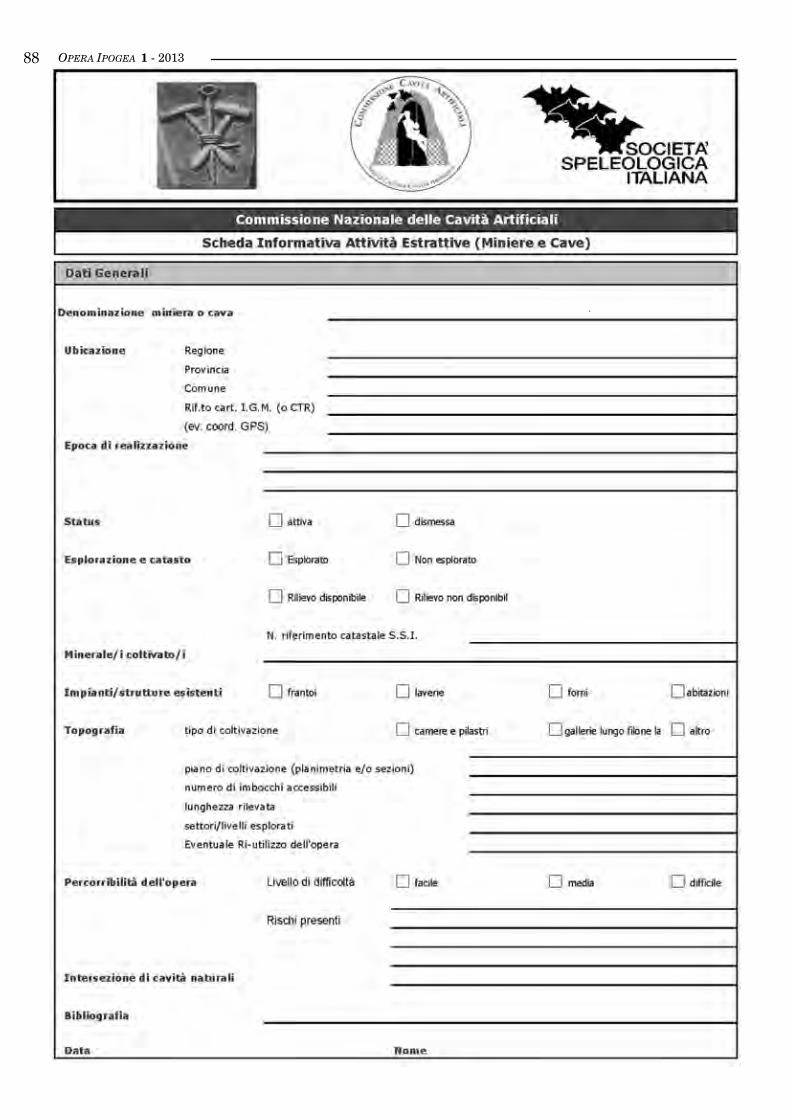
OPERA IPOGEA 1 - 2013��
OPERA IPOGEA 1 - 2013 ��
The Italian National Registerof artificial cavitiesMarco Meneghini1
1 Società Speleologica Italiana, Commissione Cavità Artificiali, Curatore del Catasto Nazionale Cavità Artificiali. Via R. Desca-ri, 14 - 38017 Mezzolombardo - (TN); e-mail: [email protected]
Abstract
The National Register of Artificial Cavities of the Italian Speleological Society, was established in 1989, as a direct emanation of the National Commission of Artificial Cavities of the Society. Initially located at Narni, since 2005 it is hosted in Bologna at the Center for Speleological Documentation “F. Anelli”.Aim of the national register is to collect and maintain the information obtained from the studies about the artificial cavities, and keep this huge amount of data available to the scientific community.The paper illustrates the procedures for the classification of the artificial cavities in Italy.
key worDS: register, artificial cavity, Italy.
Riassunto
iL catasto nazionaLe deLLe cavità artificiaLi d’itaLia
Il Catasto Nazionale delle Cavità Artificiali (CA) della Società Speleologica Italiana (S.S.I.), è stato istituito nel 1989, come diretta emanazione della Commissione Nazionale delle Cavità Artificiali S.S.I. (CNCA). Inizialmente situato a Narni, dal 2005 ha sede a Bologna, presso il Centro di Documentazione Speleologica “F. Anelli”. Il Catasto Nazionale ha lo scopo di assicurare la conservazione delle informazioni raccolte nelle esplorazioni e gli studi eseguiti sulle CA, mettendole a disposizione della comunità scientifica.Di ogni singola cavità sono raccolti, secondo le procedure e i modelli stabiliti dal Catasto Nazionale CA, i seguenti dati: denominazione, ubicazione, speleometria (ovvero i dati metrici dell’estensione accessibile delle cavità), posizione topografica, tipologia, epoca di realizzazione, terreno geologico, stato di conservazio-ne (stabilità, presenza di inquinamento, percorribilità interna). La classificazione tipologica degli ipogei è strutturata in sette categorie, identificate con una lettera maiuscola, a loro volta divise in sottotipi. Le epoche di realizzazione, originarie o presunte, delle CA, in genere, sono invece indicate con lettere minuscole.Il Catasto Nazionale CA è strutturato su base regionale, con i referenti locali che hanno il compito di inviare periodicamente al Catasto Nazionale le liste dei dati sintetici delle cavità catastate, vale a dire le informa-zioni di carattere generale, che non permettono l’esatta localizzazione di una cavità, ma la identificano chiaramente: il numero di catasto, il nome, la regione, la provincia, il comune, e la tipologia. Il numero di catasto è formato dalla sigla CA seguita da un numero progressivo regionale e dalle sigle iden-tificative della regione e della provincia (es. CA 1 La RM: cavità artificiale n. 1 del Lazio, prov. di Roma). Gli ipogei catastati direttamente al Catasto Nazionale vengono, invece, contrassegnati con un numero pro-gressivo seguito dalla sigla N (nazionale) e dalle lettere che individuano la regione e la provincia, seguendo un’unica numerazione per tutta Italia.I dati del Catasto Nazionale e dei Catasti Regionali delle CA sono pubblici, di proprietà del soggetto che li ha prodotti ed elaborati. La richiesta di accesso ai dati può essere inoltrata direttamente al curatore nazionale o ai referenti regionali. La scheda per l’inserimento delle cavità a catasto è disponibile sul sito internet del Catasto Nazionale CA http://catastoartificiali.speleo.it. A Maggio 2012 risultano iscritte al Catasto Nazio-nale circa 5000 cavità.E’ importante sottolineare che i dati relativi al complesso delle CA censite, rispecchiano in primo luogo il risultato delle ricerche effettivamente svolte piuttosto che l’effettiva presenza di CA sul territorio in termini oggettivi. In seno alla Commissione Nazionale delle Cavità Artificiali della SSI, è emersa l’esigenza di coordinare questa importante serie di dati attraverso un unico strumento di archiviazione e gestione, un Sistema In-formativo Territoriale web-oriented su tutte le cavità artificiali del nostro Paese. L’applicazione offre diffe-
OPERA IPOGEA 1 - 2013�0
The National Register of Artificial Cavities of the Italian Speleological Society (SSI) was established in 1989 fol-lowing the directives of the National Commission on Artificial Cavities, in turn set up in 1981 (nini, 1990). Aim of the work by the National Commission is to pro-mote and organize the exploration, protection, study and classification of artificial cavities. The Register, initially based in Narni, at the time being is in Bologna, at the Centre for Speleological Documentation “Franco Anelli”.The goal of the National Register is to preserve infor-mation about artificial cavities, making them available to the scientific and the speleological communities. Owner of the data is the subject who collected them, as specified by the current regulation about privacy and copyright, and by the article 1 of the Register’s regula-tion (MeneGhini, 2008).Gathering data about artificial cavities widens the geo-graphical perspective to the undergrounds shaped by human beings, supporting research and interdiscipli-nary studies which span far beyond the strictly speleo-logical domain, encompassing the activities of private and public research institutes, institutions, universi-ties, etc.The National Register is structured on a regional basis: local trustees deliver periodically the summary data of the classified cavities, i.e. general information that do not allow to localize exactly where a given cavity lies, but nonetheless identifies it through a serial number, a name, the region, province and town where it is lo-cated, and the typology of the cavity itself. Following the regulation approved in 2007, any subject intere-sted in providing data can forward directly them at the national level, and have them added to the National Register. The univocal serial number is assigned by regional trustees and consists of the acronym CA (for Artificial Cavity, in Italian), followed by a progressive regional number and the abbreviations of both region and province.Right after the foundation of the Register, in 1999 new procedures were established to catalogue and classify the different types of cavities: experts Paolo Guglia and Giulio Cappa (CaPPa, 1999) of the Italian Speleological Society classified artificial cavities in seven types (iden-tified by capital letters):A - Hydraulic works;
B - Civil Settlements works;C - Worship works;D - Military works;E - Mining works;F - Transit network;G - Others.These typologies are then further taxonomically di-vided into 36 subtypes, progressively numbered (e.g., A.1; B.4; etc.)The age of the artificial cavity is also indicated, in small letters, as follows:a = prehistoric;b = protohistoric;c = pre-roman (eg. Etrurian);d = royal and republican roman;e = imperial roman;f = late-antique (twilight of the roman empire);g = early Middle Age (until 1000 a.C. approx.);h = Middle Age;i = Renaissance (1400-1600 approx.);l = Modern Era (until the French Revolution);m = XIX century;n = XX century.
The types of cavities and the indication of their age are conventions that can be applied to the specific Italian case, but could be adapted even to fit in other coun-tries.Classifying artificial cavities has many practical im-plications: it supports the proper management of land and water resources, contributes to the protection of a fragile environment, and improves the understanding and appreciation of the cultural, archaeological and ar-tistic heritage, also focusing the attention toward its touristic potential.Today about 5000 cavities are classified in the National Register. Data about the cavities essentially portray the kind of researches that have been carried out rather than the actual composition of the different cavities: in many years of field studies it has become clear that the outcomes of researches, once they have started, often go far beyond expectations.The distribution of the different types of cavities in the Register is shown in figure 1: military works are the majority, but hydraulic and mining works, although in a more limited number, are often in a significant number.
renti funzionalità; sono, infatti, stati definiti quattro diversi profili utente. Quale strumento di conoscenza e salvaguardia, esso consentirà ad ogni categoria di utente abilitato di poter disporre facilmente di tutte le informazioni relative agli ipogei d’interesse. Oltre ai dati topografici, in esso risiederanno infatti anche dati storici, biologici, naturalistici in genere, archeologici ed architettonici, tutti utili all’individuazione degli ipogei al fine della tutela degli stessi o del territorio più esteso in cui si contestualizzano, della valorizzazione degli stessi, della sicurezza e della protezione civile, della tutela dell’ambiente dagli inquinamenti e, non da ultimo, alla ricerca ed al monitoraggio di risorse idriche sotterranee.I dati sinora disponibili on-line sono, pertanto, solamente quelli identificati come sintetici dalle procedure di accatastamento del Catasto Nazionale CA (ovvero sigla catastale, regione, provincia, comune e località, nome, tipologia e fonte dei dati).
Parole chiave: catasto, cavità artificiali, Italia.
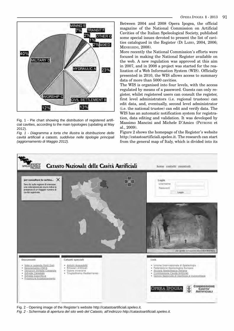
OPERA IPOGEA 1 - 2013 ��Between 2004 and 2008 Opera Ipogea, the official magazine of the National Commission on Artificial Cavities of the Italian Speleological Society, published some special issues devoted to present the list of cavi-ties catalogued in the Register (di labio, 2004, 2006; MeneGhini, 2008).More recently the National Commission’s efforts were focused in making the National Register available on the web. A new regulation was approved at this aim in 2007, and in 2008 a project was started for the rea-lization of a Web Information System (WIS). Officially presented in 2010, the WIS allows access to summary data of more than 5000 cavities.The WIS is organised into four levels, with the access regulated by means of a password. Guests can only re-gister, whilst registered users can consult the register, first level administrators (i.e. regional trustees) can edit data, and, eventually, second level administrator (i.e. the national trustee) can edit and verify data. The WIS has an automatic notification system for registra-tion, data editing and validation. It was developed by Massimo Mancini and Michele D’Amico (Petrone et al., 2009).Figure 2 shows the homepage of the Register’s website http://catastoartificiali.speleo.it. The research can start from the general map of Italy, which is divided into its
Fig. 1 - Pie chart showing the distribution of registered artifi-cial cavities, according to the main typologies (updating at May 2012).Fig. 1 - Diagramma a torta che illustra la distribuzione delle cavità artificiali a catasto, suddivise nelle tipologie principali (aggiornamento di Maggio 2012).
Fig. 2 - Opening image of the Register’s website http://catastoartificiali.speleo.it. Fig. 2 - Schermata di apertura del sito web del Catasto, all’indirizzo http://catastoartificiali.speleo.it.
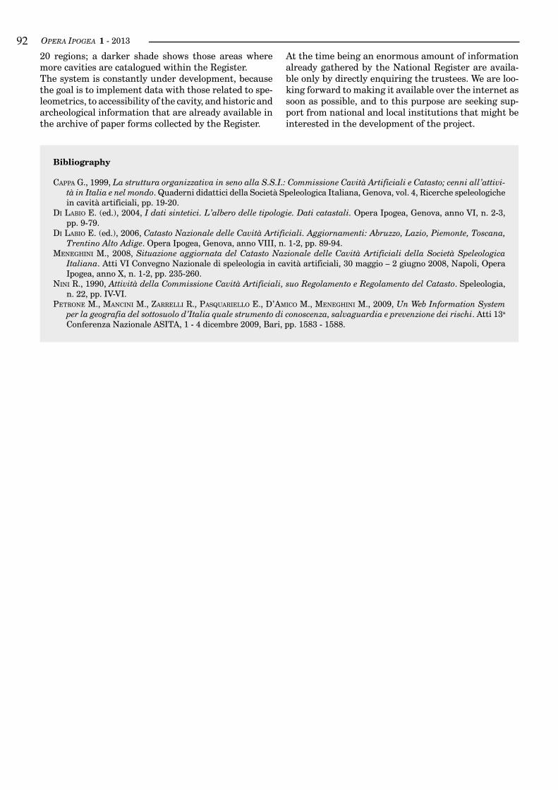
OPERA IPOGEA 1 - 2013��
bibliography
CaPPa G., 1999, La struttura organizzativa in seno alla S.S.I.: Commissione Cavità Artificiali e Catasto; cenni all’attivi-tà in Italia e nel mondo. Quaderni didattici della Società Speleologica Italiana, Genova, vol. 4, Ricerche speleologiche in cavità artificiali, pp. 19-20.
di labio E. (ed.), 2004, I dati sintetici. L’albero delle tipologie. Dati catastali. Opera Ipogea, Genova, anno VI, n. 2-3, pp. 9-79.
di labio e. (ed.), 2006, Catasto Nazionale delle Cavità Artificiali. Aggiornamenti: Abruzzo, Lazio, Piemonte, Toscana, Trentino Alto Adige. Opera Ipogea, Genova, anno VIII, n. 1-2, pp. 89-94.
MeneGhini M., 2008, Situazione aggiornata del Catasto Nazionale delle Cavità Artificiali della Società Speleologica Italiana. Atti VI Convegno Nazionale di speleologia in cavità artificiali, 30 maggio – 2 giugno 2008, Napoli, Opera Ipogea, anno X, n. 1-2, pp. 235-260.
nini R., 1990, Attività della Commissione Cavità Artificiali, suo Regolamento e Regolamento del Catasto. Speleologia, n. 22, pp. IV-VI.
Petrone M., ManCini M., zarrelli r., Pasquariello e., d’aMiCo M., MeneGhini M., 2009, Un Web Information System per la geografia del sottosuolo d’Italia quale strumento di conoscenza, salvaguardia e prevenzione dei rischi. Atti 13a Conferenza Nazionale ASITA, 1 - 4 dicembre 2009, Bari, pp. 1583 - 1588.
20 regions; a darker shade shows those areas where more cavities are catalogued within the Register.The system is constantly under development, because the goal is to implement data with those related to spe-leometrics, to accessibility of the cavity, and historic and archeological information that are already available in the archive of paper forms collected by the Register.
At the time being an enormous amount of information already gathered by the National Register are availa-ble only by directly enquiring the trustees. We are loo-king forward to making it available over the internet as soon as possible, and to this purpose are seeking sup-port from national and local institutions that might be interested in the development of the project.
OPERA IPOGEA 1 - 2013 ��
Artificial caves as a possible danger: sinkholes and other effects at the surfaceMario Parise1,2,3
1 National Research Council of Italy, IRPI, Bari, Italy; [email protected] Commission of Speleology in Artificial Cavities, Italian Speleological Society (SSI)3 UIS Commission of Speleology in Artificial Cavities
Abstract
Artificial caves may represent a possible danger, threatening the public and private properties. Presence of underground cavities beneath built-up areas implies situations of potential risk for all the man-made infra-structures and constructions above. Nevertheless, such a risk remains unknown until an effective knowledge about the real extension, the typology, and the stability conditions of the caves has been reached. Cavers must be well aware of such a risk, and be ready to provide a contribution in facing the problems that might occur. In many occasions, development of deformations at the surface, up to subsidence and eventually formation of sinkholes, has caused severe direct damage, and produced a number of related problems, from inconveniences to circulation for the local population, to decreased value of properties, and so on. The condi-tions possibly leading to occurrence of sinkholes must be therefore object of study by cavers, since they are the only “eyes” that have a direct possibility of inspection and monitoring of the underground.Artificial cavities, once abandoned, are subject to degradation of the rock mass, which may also be favored by water infiltration, presence of wastes, or other anthropogenic actions (i.e., overcharge, vibrations due to traffic, etc.). Identification of the first signs of instability underground, in the form of tension cracks, de-formations along the wall of the cavities, and first detachment of volumes of rocks, is crucial to assess the instability conditions at the site, and to plan the necessary interventions.All the above issues will be dealt with in this contribution, by means of some examples from Apulia region (southern Italy) where in recent years several episodes have occurred, mostly related to underground quar-ries. This latter typology of artificial caves has been identified by far as the most dangerous typology of arti-ficial cavity concerning instability phenomena and the likely effects to the human society.
key worDS: artificial cavities, hazard, sinkholes, civil protection.
Riassunto
cavità artificiaLi come un possibiLe pericoLo: sprofondamenti ed aLtri effetti in superficie
Le cavità di origine antropica possono costituire un potenziale pericolo, e mettere a repentaglio la pubblica e privata incolumità. La presenza di cavità sotterranee al di sotto di zone urbanizzate implica situazioni di rischio potenziale per tutte le sovrastanti infrastrutture, nonché per le costruzioni esistenti. Ciò nonostante, tale rischio resta ignoto sino a che una effettiva conoscenza della reale estensione e tipologia delle cavità, e delle loro condizioni di stabilità, siano state raggiunte. Gli speleologi sono ben consapevoli di tali rischi, e possono fornire un significativo contributo per affron-tare correttamente e nei tempi più opportuni i problemi connessi a cavità ipogee. In più di una occasione, lo sviluppo di deformazioni in superficie, sino a fenomeni di subsidenza e, infine, alla formazione di spro-fondamenti, ha causato seri danni diretti, e prodotto numerosi problemi ad essi collegati, quali ad esempio difficoltà nella circolazione del traffico per le popolazioni locali, diminuito valore delle proprietà, e così via. Le condizioni potenzialmente in grado di condurre alla occorrenza di sprofondamenti devono pertanto essere oggetto di studio da parte degli speleologi, in quanto questi costituiscono gli unici “occhi” che hanno una possibilità diretta di ispezione e monitoraggio degli ambienti sotterranei.Le cavità artificiali, una volta abbandonate, sono soggette a fenomeni di degrado dell’ammasso roccioso, che possono anche essere favoriti da infiltrazioni d’acqua, presenza di rifiuti, o da altre attività antropiche (i.e., sovraccarichi, vibrazioni per il traffico, etc.). L’identificazione dei primi segni di instabilità nel sottosuolo, sotto forma di fratture da tensione, deformazioni lungo le pareti delle cavità, e primi distacchi di volumi di
OPERA IPOGEA 1 - 2013��
inTroducTion
Sinkholes are among the main types of hazards that af-fect karst environments (Ford & WilliaMs, 2007; Parise & Gunn, 2007; WalthaM & lu, 2007; Parise, 2010a; Gutierrez, 2010; zhou & beCk, 2011). They occur as natural events, deriving from karst processes in solu-ble rocks, either cropping out at the surface or covered by other materials (WalthaM et al., 2005; Parise, 2008), or can be related to presence of underground cavities realized by man. Especially in countries where the un-derground space has been historically used by man for several purposes, occurrence of subsidence or sinkho-les related to old, often abandoned, man-made cavi-ties is quite frequent. This may become a significant problem in built-up areas, and in particular in those sectors where expansion of the urban areas included those sectors of land affected by man-made cavities.Cavers may play a very important role in the identifica-tion of the sites possibly interested by subsidence and sinkholes, since they are the only category of people that have the opportunity, and the technical skills, to move safely underground. Their survey, and the obser-vation of likely instability features affecting the rock masses, may be of crucial importance to timely iden-tifying unstable sites, and might help in carrying out studies to ascertain the effective possibility of collapse, and consequently the sinkhole occurrence at the sur-face.As an example to highlight the hazards related to the presence of man-made cavities, the Apulia region, the heel of the Italian boot, is considered in this article. Due to the almost exclusively presence of soluble rocks at the outcrop, Apulia is heavily affected by sinkholes, related to both the natural caves produced by karst pro-cesses, and the artificial cavities widely characterizing the region. As a matter of fact, Apulian land hosts some thousands of artificial caves, encompassing practically all the typologies of man-made cavities, and realized during the different time epochs.
sinkHole occurrence in aPulia
Since the beginning of last century, sinkholes in Apulia are being frequently caused by anthropogenic activity, and particularly by quarrying which, among the human activities, is certainly one of those producing the worst impacts on the natural Apulian landscape. When quar-
ries are realized underground, they become potential dangers when, once abandoned, are affected by insta-bility processes which upward stoping may eventually lead to sinkhole development at the surface.In Apulia several rock types have been interested by underground quarrying activity. In particular, the Plio-Pleistocene calcarenites, widely used for construc-tion purposes, have been extensively extracted throu-gh subterranean excavations (Parise, 2010b, 2012). Underground quarrying historically developed due to a number of reasons, namely the presence of the rocks with the best characteristics at a certain depth, and the need to preserve surface land to be used for agricultu-re. The latter point is particularly important for the lo-cal economy, which is based on agricultural production, with some products of remarkable quality such as olive oil and wines. Due to the above reasons, subterranean galleries and passages were excavated in order to rea-ch the rock levels to be cultivated for extraction. This occurred mostly at low depth (that is, not greater than 10 meters), but in some cases, depending upon the local geological and topographical settings, it was necessary to dig shafts over 30-40 m-deep. Most of these activities had to be recorded during the XIX century, and typical-ly lasted for a few decades, before being abandoned, as a combination of some accidents related to the difficult working conditions, and to high expenses of the extrac-tion works. Once abandoned, the underground sites ra-pidly were forgotten, and such a loss of memory played a crucial role in increasing the sinkhole hazard. With time, the expansion of the urban areas that occurred during the XX century often resulted in construction of buildings and communication routes just above the underground galleries. At the same time, weathering processes due to water circulation and/or to illegal di-scharge of liquid and solid wastes underground, caused a progressive decrease in the strength properties of the materials (andriani & Walsh, 2003), a factor which un-doubtedly is favorable to the degradation of the rock mass in the underground quarries and may promote development of failures (Parise & lollino, 2011).Apart from underground quarries, many other typolo-gies of man-made caves in Apulia have originated sub-sidence and/or sinkhole problems: from underground oil mills, to storage houses, cisterns and rupestrian settlements, there is record of several cases where the presence of an artificial caves, and the failure processes occurring therein, with progressive stoping toward the surface, resulted in sinkhole formations, with severe
roccia, è cruciale per valutare le condizioni di instabilità al sito, e per pianificare le necessarie operazioni di intervento.Gli argomenti su citati sono trattati nel presente contributo, per mezzo di alcuni esempi dalla Puglia (Italia meridionale), una regione dove nel corso degli ultimi anni si sono verificati numerosi eventi di sprofonda-mento, la maggior parte dei quali risulta connessa a cave sotterranee. Questa tipologia di cavità artificiali è stata pertanto identificata come la più pericolosa per quello che riguarda la possibilità di occorrenza di fenomeni di instabilità, e i possibili effetti negativi derivanti alla società.
Parole chiave: cavità artificiali, pericolosità, sprofondamenti, protezione civile.
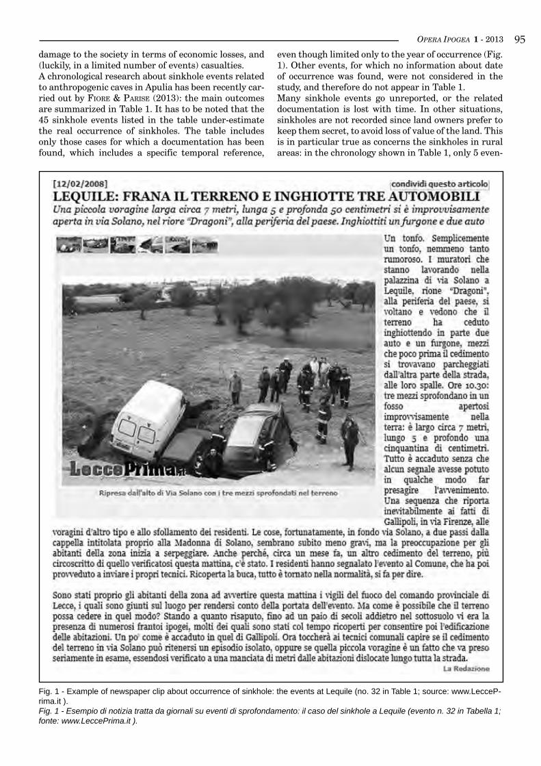
OPERA IPOGEA 1 - 2013 ��damage to the society in terms of economic losses, and (luckily, in a limited number of events) casualties.A chronological research about sinkhole events related to anthropogenic caves in Apulia has been recently car-ried out by Fiore & Parise (2013): the main outcomes are summarized in Table 1. It has to be noted that the 45 sinkhole events listed in the table under-estimate the real occurrence of sinkholes. The table includes only those cases for which a documentation has been found, which includes a specific temporal reference,
even though limited only to the year of occurrence (Fig. 1). Other events, for which no information about date of occurrence was found, were not considered in the study, and therefore do not appear in Table 1.Many sinkhole events go unreported, or the related documentation is lost with time. In other situations, sinkholes are not recorded since land owners prefer to keep them secret, to avoid loss of value of the land. This is in particular true as concerns the sinkholes in rural areas: in the chronology shown in Table 1, only 5 even-
Fig. 1 - Example of newspaper clip about occurrence of sinkhole: the events at Lequile (no. 32 in Table 1; source: www.LecceP-rima.it ).Fig. 1 - Esempio di notizia tratta da giornali su eventi di sprofondamento: il caso del sinkhole a Lequile (evento n. 32 in Tabella 1; fonte: www.LeccePrima.it ).
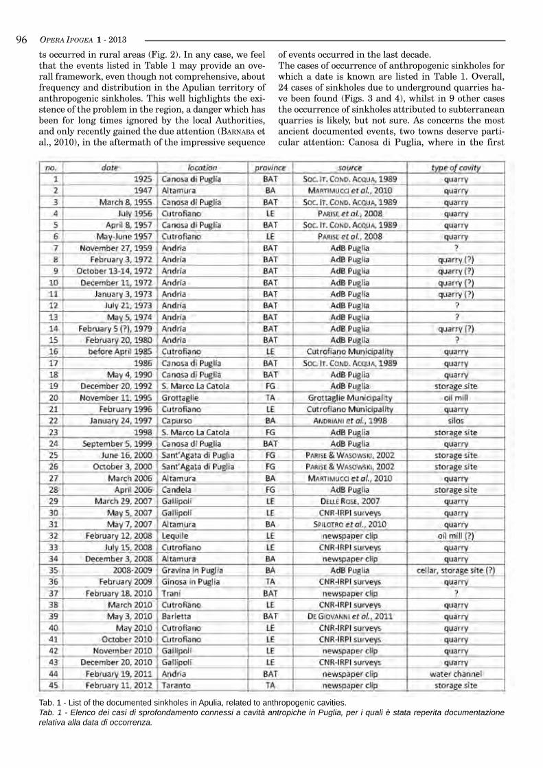
OPERA IPOGEA 1 - 2013��ts occurred in rural areas (Fig. 2). In any case, we feel that the events listed in Table 1 may provide an ove-rall framework, even though not comprehensive, about frequency and distribution in the Apulian territory of anthropogenic sinkholes. This well highlights the exi-stence of the problem in the region, a danger which has been for long times ignored by the local Authorities, and only recently gained the due attention (barnaba et al., 2010), in the aftermath of the impressive sequence
Tab. 1 - List of the documented sinkholes in Apulia, related to anthropogenic cavities.Tab. 1 - Elenco dei casi di sprofondamento connessi a cavità antropiche in Puglia, per i quali è stata reperita documentazione relativa alla data di occorrenza.
of events occurred in the last decade.The cases of occurrence of anthropogenic sinkholes for which a date is known are listed in Table 1. Overall, 24 cases of sinkholes due to underground quarries ha-ve been found (Figs. 3 and 4), whilst in 9 other cases the occurrence of sinkholes attributed to subterranean quarries is likely, but not sure. As concerns the most ancient documented events, two towns deserve parti-cular attention: Canosa di Puglia, where in the first
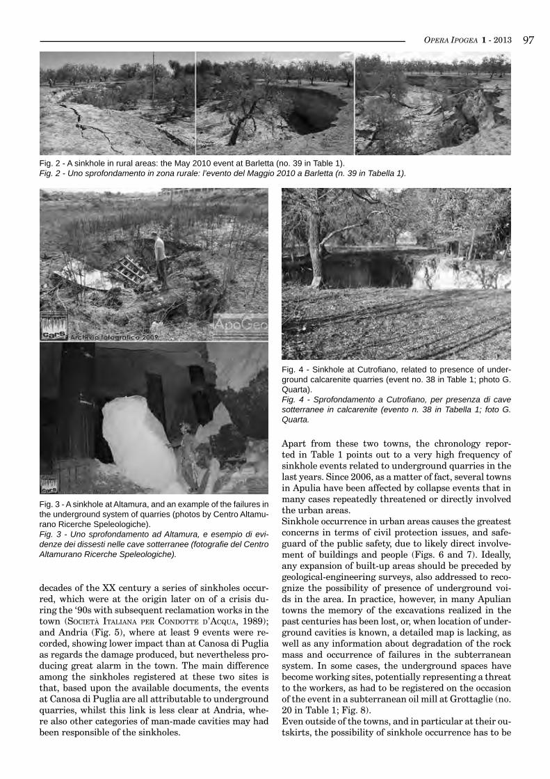
OPERA IPOGEA 1 - 2013 ��
decades of the XX century a series of sinkholes occur-red, which were at the origin later on of a crisis du-ring the ‘90s with subsequent reclamation works in the town (soCietà italiana Per Condotte d’aCqua, 1989); and Andria (Fig. 5), where at least 9 events were re-corded, showing lower impact than at Canosa di Puglia as regards the damage produced, but nevertheless pro-ducing great alarm in the town. The main difference among the sinkholes registered at these two sites is that, based upon the available documents, the events at Canosa di Puglia are all attributable to underground quarries, whilst this link is less clear at Andria, whe-re also other categories of man-made cavities may had been responsible of the sinkholes.
Fig. 2 - A sinkhole in rural areas: the May 2010 event at Barletta (no. 39 in Table 1).Fig. 2 - Uno sprofondamento in zona rurale: l’evento del Maggio 2010 a Barletta (n. 39 in Tabella 1).
Fig. 3 - A sinkhole at Altamura, and an example of the failures in the underground system of quarries (photos by Centro Altamu-rano Ricerche Speleologiche).Fig. 3 - Uno sprofondamento ad Altamura, e esempio di evi-denze dei dissesti nelle cave sotterranee (fotografie del Centro Altamurano Ricerche Speleologiche).
Fig. 4 - Sinkhole at Cutrofiano, related to presence of under-ground calcarenite quarries (event no. 38 in Table 1; photo G. Quarta).Fig. 4 - Sprofondamento a Cutrofiano, per presenza di cave sotterranee in calcarenite (evento n. 38 in Tabella 1; foto G. Quarta.
Apart from these two towns, the chronology repor-ted in Table 1 points out to a very high frequency of sinkhole events related to underground quarries in the last years. Since 2006, as a matter of fact, several towns in Apulia have been affected by collapse events that in many cases repeatedly threatened or directly involved the urban areas.Sinkhole occurrence in urban areas causes the greatest concerns in terms of civil protection issues, and safe-guard of the public safety, due to likely direct involve-ment of buildings and people (Figs. 6 and 7). Ideally, any expansion of built-up areas should be preceded by geological-engineering surveys, also addressed to reco-gnize the possibility of presence of underground voi-ds in the area. In practice, however, in many Apulian towns the memory of the excavations realized in the past centuries has been lost, or, when location of under-ground cavities is known, a detailed map is lacking, as well as any information about degradation of the rock mass and occurrence of failures in the subterranean system. In some cases, the underground spaces have become working sites, potentially representing a threat to the workers, as had to be registered on the occasion of the event in a subterranean oil mill at Grottaglie (no. 20 in Table 1; Fig. 8).Even outside of the towns, and in particular at their ou-tskirts, the possibility of sinkhole occurrence has to be
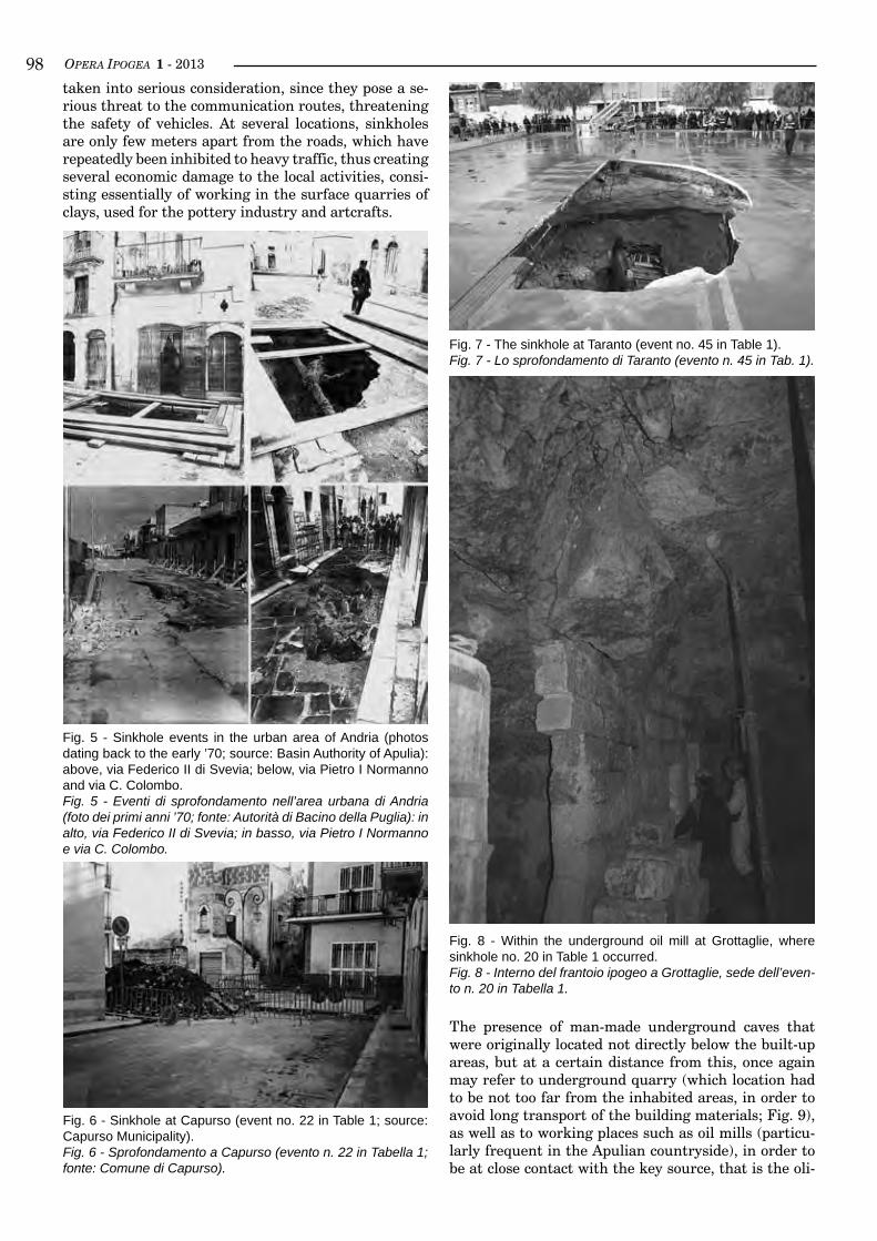
OPERA IPOGEA 1 - 2013��
Fig. 6 - Sinkhole at Capurso (event no. 22 in Table 1; source: Capurso Municipality).Fig. 6 - Sprofondamento a Capurso (evento n. 22 in Tabella 1; fonte: Comune di Capurso).
Fig. 7 - The sinkhole at Taranto (event no. 45 in Table 1).Fig. 7 - Lo sprofondamento di Taranto (evento n. 45 in Tab. 1).
taken into serious consideration, since they pose a se-rious threat to the communication routes, threatening the safety of vehicles. At several locations, sinkholes are only few meters apart from the roads, which have repeatedly been inhibited to heavy traffic, thus creating several economic damage to the local activities, consi-sting essentially of working in the surface quarries of clays, used for the pottery industry and artcrafts.
The presence of man-made underground caves that were originally located not directly below the built-up areas, but at a certain distance from this, once again may refer to underground quarry (which location had to be not too far from the inhabited areas, in order to avoid long transport of the building materials; Fig. 9), as well as to working places such as oil mills (particu-larly frequent in the Apulian countryside), in order to be at close contact with the key source, that is the oli-
Fig. 5 - Sinkhole events in the urban area of Andria (photos dating back to the early ’70; source: Basin Authority of Apulia): above, via Federico II di Svevia; below, via Pietro I Normanno and via C. Colombo.Fig. 5 - Eventi di sprofondamento nell’area urbana di Andria (foto dei primi anni ’70; fonte: Autorità di Bacino della Puglia): in alto, via Federico II di Svevia; in basso, via Pietro I Normanno e via C. Colombo.
Fig. 8 - Within the underground oil mill at Grottaglie, where sinkhole no. 20 in Table 1 occurred.Fig. 8 - Interno del frantoio ipogeo a Grottaglie, sede dell’even-to n. 20 in Tabella 1.
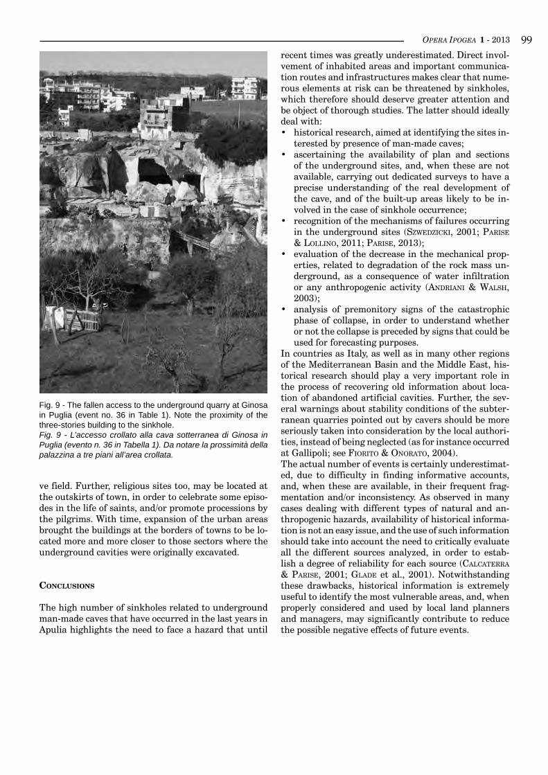
OPERA IPOGEA 1 - 2013 ��
Fig. 9 - The fallen access to the underground quarry at Ginosa in Puglia (event no. 36 in Table 1). Note the proximity of the three-stories building to the sinkhole.Fig. 9 - L’accesso crollato alla cava sotterranea di Ginosa in Puglia (evento n. 36 in Tabella 1). Da notare la prossimità della palazzina a tre piani all’area crollata.
ve field. Further, religious sites too, may be located at the outskirts of town, in order to celebrate some episo-des in the life of saints, and/or promote processions by the pilgrims. With time, expansion of the urban areas brought the buildings at the borders of towns to be lo-cated more and more closer to those sectors where the underground cavities were originally excavated.
conclusions
The high number of sinkholes related to underground man-made caves that have occurred in the last years in Apulia highlights the need to face a hazard that until
recent times was greatly underestimated. Direct invol-vement of inhabited areas and important communica-tion routes and infrastructures makes clear that nume-rous elements at risk can be threatened by sinkholes, which therefore should deserve greater attention and be object of thorough studies. The latter should ideally deal with:• historical research, aimed at identifying the sites in-
terested by presence of man-made caves;• ascertaining the availability of plan and sections
of the underground sites, and, when these are not available, carrying out dedicated surveys to have a precise understanding of the real development of the cave, and of the built-up areas likely to be in-volved in the case of sinkhole occurrence;
• recognition of the mechanisms of failures occurring in the underground sites (szWedziCki, 2001; Parise & lollino, 2011; Parise, 2013);
• evaluation of the decrease in the mechanical prop-erties, related to degradation of the rock mass un-derground, as a consequence of water infiltration or any anthropogenic activity (andriani & Walsh, 2003);
• analysis of premonitory signs of the catastrophic phase of collapse, in order to understand whether or not the collapse is preceded by signs that could be used for forecasting purposes.
In countries as Italy, as well as in many other regions of the Mediterranean Basin and the Middle East, his-torical research should play a very important role in the process of recovering old information about loca-tion of abandoned artificial cavities. Further, the sev-eral warnings about stability conditions of the subter-ranean quarries pointed out by cavers should be more seriously taken into consideration by the local authori-ties, instead of being neglected (as for instance occurred at Gallipoli; see Fiorito & onorato, 2004).The actual number of events is certainly underestimat-ed, due to difficulty in finding informative accounts, and, when these are available, in their frequent frag-mentation and/or inconsistency. As observed in many cases dealing with different types of natural and an-thropogenic hazards, availability of historical informa-tion is not an easy issue, and the use of such information should take into account the need to critically evaluate all the different sources analyzed, in order to estab-lish a degree of reliability for each source (CalCaterra & Parise, 2001; Glade et al., 2001). Notwithstanding these drawbacks, historical information is extremely useful to identify the most vulnerable areas, and, when properly considered and used by local land planners and managers, may significantly contribute to reduce the possible negative effects of future events.
OPERA IPOGEA 1 - 2013�00
bibliography
andriani G.F., quarto r., zinCo M.R., 1998, Rinvenimento di ipogei nel centro storico di Capurso (BA) e rischio di dis-sesti. Quarry & Construction, aprile 98, pp. 47-54.
andriani G.F., Walsh N., 2003, Fabric, porosity and water permeability of calcarenites from Apulia (SE Italy) used as building and ornamental stone. Bulletin of Engineering Geology and the Environment, vol. 62, pp. 77-84.
barnaba F., CaGGiano t., Castorani a., delle rose M., di santo a.r., draGone v., Fiore a., liMoni P.P., Parise M., santa-loia F., 2010, Sprofondamenti connessi a cavità antropiche nella regione Puglia. Proc. 2nd Int. Workshop “Sinkholes. The catastrophic sinking in natural and anthropic environments”, Rome, 3-4 December 2009, pp. 653-672.
CalCaterra d., Parise M., 2001, The contribution of historical information in the assessment of the landslide hazard. In: Glade t., albini P., FranCes F. (eds.), The Use of Historical Data in Natural Hazard Assessments. Adv. in Nat. and Techn. Hazards Res. 17, Kluwer Acad Publ, pp. 201-217.
de Giovanni a., MartiMuCCi v., Marzulli M., Parise M., PentiMone n., sPortelli D., 2011, Operazioni di rilievo e analisi preliminare dello sprofondamento in località San Procopio (Barletta, 2-3 maggio 2010). Proc. VII Nat. Congr. Spe-leology in Artificial Cavities, Urbino, Opera Ipogea, n. 1/2, pp. 151-158.
delle rose M., 2007, La voragine di Gallipoli e le attività di Protezione Civile dell’IRPI-CNR. Geologi e Territorio, 4/2006-1/2007, pp. 3-12.
Fiore a., Parise M., 2013, Cronologia degli eventi di sprofondamento in Puglia, con particolare riferimento alle intera-zioni con l’ambiente antropizzato. Memorie Descrittive Carta Geologica d’Italia.
Fiorito F., onorato R., 2004, Le cave sotterranee di Colle San Lazzaro - Gallipoli. Proc. Meeting “Spelaion 2004”, Lecce, pp. 125-136.
Ford d., WilliaMs P., 2007, Karst hydrogeology and geomorphology. Wiley, New York.Glade t., albini P., FranCes F. (eds), 2001, The Use of Historical Data in Natural Hazard Assessments. Adv. in Nat. and
Techn. Hazards Res. 17, Kluwer Acad Publ.Gutierrez F., 2010, Hazards associated with karst. In: alCantara-ayala i., Goudie a.s. (eds), Geomorphological hazards
and disaster prevention. Cambridge Univ Press, pp. 161-176.MartiMuCCi v., raGone G., denora a., Cristallo F., 2010, Le cave di tufo di Altamura – Prime relazioni e notizie sulle
esplorazioni. Atti del XII Incontro Regionale di Speleologia “Spelaion 07”, Altamura, 7-9 dicembre 2007, pp. 91-102.
Parise M., 2008, Rock failures in karst. In: ChenG z., zhanG J., li z., Wu F., ho k. (eds), Landslides and Engineered Slopes. Proc. 10th Int. Symp. on Landslides, Xi’an (China), June 30–July 4, 2008, vol. 1, pp 275-280.
Parise M., 2010a, Hazards in karst. In: bonaCCi O. (ed.), Proc. Int. Interdisc. Scientific Conf. “Sustainability of the karst environment. Dinaric karst and other karst regions”, Plitvice Lakes (Croatia), 23-26 Sept. 2009, IHP-UNESCO, Series on Groundwater 2, pp 155-162.
Parise M., 2010b, The impacts of quarrying in the Apulian karst. In: CarrasCo F., la Moreaux J.W., duran valsero J.J., andreo b. (eds), Advances in research in karst media. Springer, pp 441-447.
Parise M., 2012, A present risk from past activities: sinkhole occurrence above underground quarries. Carbonates and Evaporites, vol. 27 (2), pp. 109-118.
Parise M., 2013, Recognition of instability features in artificial cavities. Proceedings 16th International Congress of Speleology, Brno (Czech Republic), in press.
Parise M., WasoWski J., 2002, Prime considerazioni sui fenomeni di dissesto idrogeologico del giugno-ottobre 2000 nel comprensorio comunale di Sant’Agata di Puglia (prov. di Foggia). Atti del Convegno “Il dissesto idrogeologico: in-ventario e prospettive”, Roma, 5 giugno 2001, Accademia dei Lincei, vol. 181, pp. 449-456.
Parise M., Gunn J. (eds) 2007, Natural and anthropogenic hazards in karst areas: Recognition, Analysis and Mitiga-tion. Geol Soc London, sp publ 279, 202 pp.
Parise M., lollino P., 2011, A preliminary analysis of failure mechanisms in karst and man-made underground caves in Southern Italy. Geomorphology, vol. 134 (1-2), pp. 132-143.
Parise M., de PasCalis a., de PasCalis F., donno G., inGusCio S., 2008, Cavità sotterranee a fini estrattivi, e loro con-nessione con fenomeni di sprofondamento e subsidenza in agro di Cutrofiano (Lecce). Atti “Spelaion 2006”, Borgo Celano, pp. 55-69.
soCietà italiana Per Condotte d’aCqua s.P.A., 1989, Interventi urgenti a salvaguardia della pubblica e privata inco-lumità. Rilevamento cavità sotterranee della città, studi e indagini geognostiche del territorio. Relazione generale. Municipality of Canosa di Puglia, 170 pp.
sPilotro G., sPeCChio v., PePe P., 2010, L’evento del 07.05.2007 di Via Barcellona, Altamura. Il contributo del CARS alle strategie d’intervento di valutazione del rischio connesso (Provincia di Bari, Puglia). Atti del XII Incontro Regionale di Speleologia “Spelaion 07”, Altamura, 7-9 dicembre 2007, pp. 103-107.
szWedziCki T., 2001, Geotechnical precursors to large-scale ground collapse in mines. International Journal of Rock Mechanics and Mining Science, vol. 38, pp. 957-965.
WalthaM t., lu Z., 2007, Natural and anthropogenic rock collapse over open caves. In: Parise M., Gunn J. (eds), Natural and anthropogenic hazards in karst areas: recognition, analysis, and mitigation. Geol Soc London, sp publ 279, pp. 13-21.
WalthaM t., bell F., CulshaW M., 2005, Sinkholes and subsidence: karst and cavernous rocks in engineering and con-struction. Springer, 382 pp.
zhou W., beCk B.F., 2011, Engineering issues in karst. In: van beynen P. (ed), Karst Management. Springer, pp. 9-45.
OPERA IPOGEA 1 - 2013 �0�Guidelines for Authors
Manuscript submissionManuscripts, not published before, must be prepared in Italian or English language and sent in digital format, including figures and tables, to the Editorial Board at the following address: Sossio Del Prete, via Ferrarecce 7 - 81100 Caserta, Italy.
Indications by the Editorial Board and Authors’ instructions• The articles must deal with speleology in artificial caves, or related studies and researches.• Authors must indicate their affiliation, which will be shown on the first page of the manuscript.• In case the manuscript is written by two or more Authors, the reference Author must be indicated (name, surname, postal address, E-mail).• Length of the manuscript must not exceed 50,000 spaces, including the figures. In exceptional circumstances, the matter will be examined
by the Editorial Board.• Figure captions must be presented in Italian and English.
Organization of the text• Starting from the first page, the manuscript must include: italian title, english title, name and surname of Authors, address and affiliation of
Authors, extended abstract in italian, abstract in english, key words (in italian and english).• The manuscript written in english must be preceeded by an english abstract and an extended italian abstract (maximum length 1000 spac-
es).• Each page must be printed only on one face, with single spacing, 12 pt, Arial or Times New Roman, and must be numbered.• The title must be written in BOLD UPPER CASE, centered. The 1st order sub-titles must not be numbered, and must be written in bold
lower case, left alignment; the 2nd order sub-titles must be written in bold italics lower case, left alignment.• All the figures must be cited in the text, numbered progressively in Arab numbers between brackets (fig. 1, tab. 1). In the context of a sen-
tence, the figure may also be indicated as: ..... in figure .....• Notes must be placed as footnotes.• References in the text must be indicated between brackets, as follows: Author, year (separated by a comma). In case of more works, these
must be indicated in chronological order, separated by a semi-colon (i.e. Pisano & sanna, 1999; Gortani et al., 2000). Multiple articles by the same Author, published in the same year, must be indicated with lower case letters after the year (i.e.: ...., 1999a; ....1999b).
• In case of long and repeated names in text, these must be fully indicated when cited the first time, and followed by its acronym between brackets, as in the following example: Tufo Giallo Napoletano (TGN). The acronym will be used in the following text.
• Cardinal points must be fully indicated in lower case letters (i.e.: north, east south east from Rome). Directions must be indicated in upper case letters (i.e.: N-S; ESE-WNW).
• Measurement units must belong to the International System (km, m, cm, mm); in case of ancient measurement units, the equivalent metric unit must be shown between brackets.
• Authors are responsible of the manuscript sent for publication, also as regards copyright of pictures and drawings.
Acknowledgements• Acknowledgements at the end of the text must be preceeded by the word Acknowledgements in bold, 12 pt, left alignment.
References• The reference list must include all the references cited in the text.• Articles in preparation cannot be cited, whilst articles effectively in press (already accepted for publication) may be cited.• The references must be listed at the end of the text, in alphabetical order, after the word References, bold, 12 pt, left alignment. The referen-
ces must be prepared according to the following example: ietto a., sGrosso i., 1963, Sulla presenza di una stazione paleolitica in un riparo sotto roccia nei dintorni di Cicciano (Nola). Boll. Soc. Nat. in Napoli, vol. 2, pp. 26-30.
Figures• The figures must be numbered progressively, and accompanied by the english and italian captions.• Photographs must be of high quality, in 300 dpi resolution. In case of historical photos a high quality scan is required.• Letters and numbers must be, after printing, between 1 and 5 mm. The use of Arial or Helvetica font (font size not lower than 6-8 pt) is rec-
ommended.• All the maps and topographic surveys must present a metric scale, and indication of North.• In case of figures from published papers, the source must always be indicated (and fully reported in the reference list).• The Editorial Board may modify the size of figures proposed by the Author.• The caption must always include indication of the author of the photograph or drawing.
Digital copyManuscripts must be prepared in MS Word (Windows 95 or later versions), following these guidelines. The complete manuscripts must include text, drawings and photographs (300 dpi resolution), and be sent exclusively on CD-Rom or DVD-Rom.Photographs and figures must be in format .tif or .jpeg with 300 dpi resolution.The material must be sent exclusively to the following address:Sossio Del Prete, via Ferrarecce 7 - 81100 Caserta, Italy. Cell. phone: 338-7621231. E-mail: [email protected]
All mAnuscripts prepAred not in AccordAnce to these guidelines will be sent bAck to Authors.
OPERA IPOGEA 1 - 2013�0�Indicazioni per gli Autori
Sottomissione dei manoscrittiI manoscritti, inediti, dovranno essere redatti in italiano o in inglese ed essere inviati su supporto informatico completi di iconografie al Comi-tato di Redazione al seguente indirizzo: Sossio Del Prete, via Ferrarecce 7 - 81100 Caserta.
Indicazioni del Comitato di Redazione e istruzioni per gli Autori• Gli articoli devono riguardare tematiche riguardanti la speleologia in Cavità Artificiali e studi e applicazioni ad essa attinenti.• Gli autori dovranno indicare la loro afferenza (gruppo speleologico, struttura universitaria, etc.), che sarà riportata sulla prima pagina del
manoscritto.• Nel caso il manoscritto sia redatto da più Autori, specificare il nome dell’Autore di riferimento (nome, cognome, recapito postale e posta
elettronica);• La lunghezza dei lavori non deve superare le 50.000 battute, figure incluse salvo eccezioni da concordare con il CdR;• Le didascalie delle figure devono essere bilingui (italiano ed inglese).
Organizzazione del testo• A partire dalla prima pagina il lavoro deve contenere: Titolo del lavoro in italiano, titolo del lavoro in inglese, nome e cognome degli Autori,
indirizzi e afferenze degli Autori, riassunto in italiano, abstract esteso in inglese e termini chiave (italiano e inglese).• Il manoscritto redatto in italiano deve essere preceduto da un riassunto in italiano e un abstract esteso in inglese che non devono superare
rispettivamente le 1000 battute.• Ogni pagina deve essere dattiloscritta soltanto sulla prima faccia con interlinea singola, 12 pt, Arial o Times New Roman e deve essere nu-
merata.• Il titolo dell’articolo va scritto in GRASSETTO MAIUSCOLO con allineamento al centro. I titoli di paragrafo non vanno numerati e vanno
scritti in grassetto minuscolo con allineamento a sinistra, mentre i titoli di eventuali sottoparagrafi vanno scritti in grassetto corsivo minu-scolo sempre con allineamento a sinistra.
• Tutte le illustrazioni devono essere richiamate nel testo con numerazione araba progressiva fra parentesi tonde secondo la dicitura (fig. 1, tab. 1), parti delle figure devono essere indicate nel testo con la dicitura (fig. 1a). Nel contesto di una frase le figure possono essere indicate anche per esteso (es.: ….nella figura….).
• Eventuali note dovranno essere poste a piè di pagina.• Le citazioni bibliografiche nel testo vanno indicate fra parentesi tonde: Nome dell’Autore, virgola, anno di edizione. Nel caso di più la-
vori citati in serie devono essere riportati in ordine cronologico separati da punto e virgola (es. Pisano & sanna, 1999; Gortani et al., 2000). Più articoli dello stesso Autore pubblicati nello stesso anno vanno distinti con lettere minuscole dopo la data (es.:…1999a; …1999b).
• Nel caso di denominazioni lunghe e ricorrenti nel testo si consiglia di esplicitare la denominazione per esteso solo la prima vol-ta, facendola seguire, tra parentesi tonde, dal suo acronimo che verrà utilizzato successivamente; es.: Tufo Giallo Napoletano (TGN).
• I punti cardinali vanno citati per esteso con la lettera minuscola (es.: a nord, a est sud est di Roma), mentre nel caso di direzioni essi vanno indicati con la sigla maiuscola (es.: N-S; ESE-WNW).
• Le unità di misura devono essere metriche del Sistema Internazionale (km, m, mm) o nel caso di antiche unità di misura deve essere indicato, tra parentesi tonde, l’equivalente in unità metriche. Per le unità di misura non va usato il punto.
• Gli Autori sono responsabili del testo inviato per la pubblicazione, e si assumono ogni responsabilità relativa a diritti di copyright su fotogra-fie e immagini.
Ringraziamenti• I ringraziamenti alla fine del testo vanno preceduti dalla dicitura Ringraziamenti allineata a sinistra, grassetto, 12 pt. (così come un titolo di
paragrafo).
Citazioni bibliografiche• Nell’elenco bibliografico finale vanno riportati solo i riferimenti citati nel testo;• Non sono ammesse citazioni di lavori in preparazione mentre possono essere fatti riferimenti a lavori effettivamente in corso di stampa; • La letteratura citata va elencata alla fine del manoscritto in ordine alfabetico e preceduta dalla dicitura Bibliografia allineata a sini-
stra, grassetto, 12 pt. Vanno riportati solo i riferimenti citati nel testo e la lista va compilata in ordine alfabetico per Autore del tipo: CoGnome nome, anno di pubblicazione, titolo, rivista, volume, pagine, editore, altro. Esempio: ietto a., sGrosso i., 1963, Sul-la presenza di una stazione paleolitica in un riparo sotto roccia nei dintorni di Cicciano (Nola). Boll. Soc. Nat. in Napoli, vol. 2, pp. 26-30.
Figure e disegni• Disegni (in formato massimo A4), foto e diapositive devono essere numerati progressivamente ed essere accompagnati dalle relative dida-
scalie bilingui stampate separatamente dal testo e scritte nelle stesse caratteristiche del testo (file .doc).• Le foto dovranno essere di ottima qualità. Nel caso di foto storiche saranno accettate immagini a stampa, di qualsiasi formato. È possibile consegnare foto digitali, ottenute con fotocamere di qualità professionale, in risoluzioni che consentano una resa di 300 dpi.• Le lettere ed i numeri in stampa, dopo la riduzione, dovranno essere compresi tra 1 e 5 mm. Si consigliano i caratteri Arial o Helvetica con
dimensioni non inferiori a 6-8 pt.• Tutte le mappe o i rilievi topografici devono riportare una scala metrica e indicazione del Nord.• Nel caso in cui si utilizzino illustrazioni tratte da lavori già pubblicati va sempre indicata la fonte da cui è tratta.• Il CdR si riserva comunque la facoltà di modificare le dimensioni proposte dall’Autore.• Indicare sempre nelle relative didascalie l’autore della foto o del disegno, ovvero la fonte da cui è tratta.
Copie su supporto informaticoGli articoli devono essere elaborati in MS Word per Windows 95 o successivi (file .doc), senza impaginazione (evitando quindi rientri, inter-linea diversificata, tabulazioni, bordi, sfondi). Eventuali esigenze di particolari impaginazioni dovranno essere descritte a parte sulle versioni a stampa. I lavori completi (testi, disegni, fotografie e scansioni con risoluzione minima di 300 dpi) vanno inviati esclusivamente su supporto informatico: CD-Rom, ovvero DVD-Rom.Per foto e figure predisposte con il computer devono essere inviati i file in formato .Tif o .Jpeg con risoluzione non inferiore a 300 dpi.
Il materiale va inviato esclusivamente al responsabile del CdR Sossio Del Prete all’indirizzo sotto indicato:Sossio Del Prete, Via Ferrarecce 7, 81100 Caserta (CE), cell. 338.7621231, mail: [email protected]
tutti i mAnoscritti che non si AtterrAnno Alle presenti norme sArAnno rispediti Agli Autori per il necessArio AdeguAmento.
OPERA IPOGEA 1 - 2013 �0�
Name ................................................................................................ Surname ................................................................................................................................................................
Society, Association, Institute ………………………..........................................................................................................….............................................................................
Addresses …………............... .........................................................................................................................................................................................................................................
Postal Code ...................................... City ................................................................................................................................................................ State …..…..........................
Tax number - Vat number (necessary for invoicing) …...........................................................................................................................................................
Address where the invoice wil be sent (if different): ………………............................................................................……………………………………….…..
…………………………………………………….........................................................................................................................................…………………………………………………………………..…
Telephone .................../…………...............................…….. Other tel. …................/………...............................………… Fax ….............../………………..…….....…………….
E-mail address for communications: …...............................................................................................................................................................………………………….
Please send the compiled page and a proof of payment to:Opera Ipogea Editorial Office - Subscriptions and Sales: [email protected]
Opera Ipogea 2013Journal of Speleology in Artificial Cavities
Subscription Coupon
PRICES 2013Subscription for UE (2 numbers) .................................................................................................................................................................................. € 25,00Subscription for other countries ................................................................................................................................................................................... € 35,00
Older editions:1-2 2008 (Special: Proceedings of Naples Conference) ...............................................................................................................................€ 40,001-2 2011 (Special: Proceedings of Urbino Conference) ...............................................................................................................................€ 40,001-2007 – 2-2012 (per copy) .................................................................................................................................................................................................... € 15,00
Bank Transfer to: Società Speleologica ItalianaBank name: Banca di Bologna - IBan: IT22s 08883 02402 CC0200202447 - BIC/sWIfT: BDBOIT21BOM
PayMenT TO POsTal Bank aCCOunT:number58504002,accountowner:SocietàSpeleologicaItalianaViaZamboni,67-40126Bologna
CreDIT CarD,sendafaxto051/250049(BibliotecaAnelli)inwhichyouspecifythecardnumber,theexpirydate, tha name of the owner of the card and the amount to be charged, as well as the purpose of payment.
Attention: in the purpose of payment please write: Subscription Opera Ipogea 2013
CONTACT INFORMATION
reDazIOne OPera IPOGeaC/O sOssIO Del PreTe VIa ferrareCCe, 7 - 81100 [email protected] - [email protected] site: www.operaipogea.it
OPERA IPOGEA 1 - 2013�0�
Nome ................................................................................................. Cognome .............................................................................................................................................................
Società, Associazione, Istituto ………………………........................................................................................................….............................................................................
Indirizzo …………........................................................................................................................................................................................................................................................................
CAP ...................................... Città ............................................................................................................................................................................................. Prov. ……...................
Cod. Fiscale - P. IVA (necessari per la fatturazione) …............................................................................................................................................................
Indirizzo di spedizione delle fatture (se diverso): ………………....................................................................................……………………………………….…..
……………………………………………………..........................................................................................................................................…………………………………………………………………..…
Telefono .................../…………........................…….. Altro recapito tel. …................/……….........................………… Fax ….............../…………..……………………….
Indirizzo e-mail per comunicazioni: …...................................................................................................................................................................………………………….
Inviare questa pagina, compilata, unita all’attestazione di pagamento a:Redazione Opera Ipogea - Abbonamenti e Vendite: [email protected]
Coupon Abbonamento Opera Ipogea 2013Rivista semestrale della Società Speleologica Italiana
Autorizzazione del Tribunale di Bologna n. 7702 dell’11 ottobre 2006
TARIFFE 2013Abbonamento ordinario Italia 2013 (due numeri) ...................................................................................................................................... € 25,00Abbonamento Europa (due numeri)............................................................................................................................................................................ € 25,00Abbonamento Paesi extra europei .............................................................................................................................................................................. € 35,00
Arretrati:1-2007 – 2-2012 (a copia) ........................................................................................................................................................................................................ € 15,00Numero 1-2/2008 (Speciale Atti Convegno Napoli) .................................................................................................................................. € 40,00Numero 1-2/2011 (Speciale Atti Convegno Urbino) .................................................................................................................................. € 40,00
BOnIfICO BanCarIO a favore della Società Speleologica ItalianapressoBancadiBologna-FilialediBologna-Mazzini-viaBellaria,32-40139BolognaIBan: IT22s 08883 02402 CC0200202447 - sWIfT/BIC: BDBOIT21BOM
VersaMenTO su C.C.P.numero58504002intestatoa:SocietàSpeleologicaItaliana-ViaZamboni,67-40126Bologna
CarTa DI CreDITO,inviareunfaxalnumero051/250049(BibliotecaAnelli)conilnumerodellacarta,scadenza,nome dell’intestatario, importo da trattenere e causale del pagamento.
Attenzione nella causale specificare sempre Abbonamento Opera Ipogea anno 2013
CONTATTI
reDazIOne OPera IPOGeaC/O sOssIO Del PreTeVIa ferrareCCe, 7 - 81100 [email protected] / [email protected] web: www.operaipogea.it
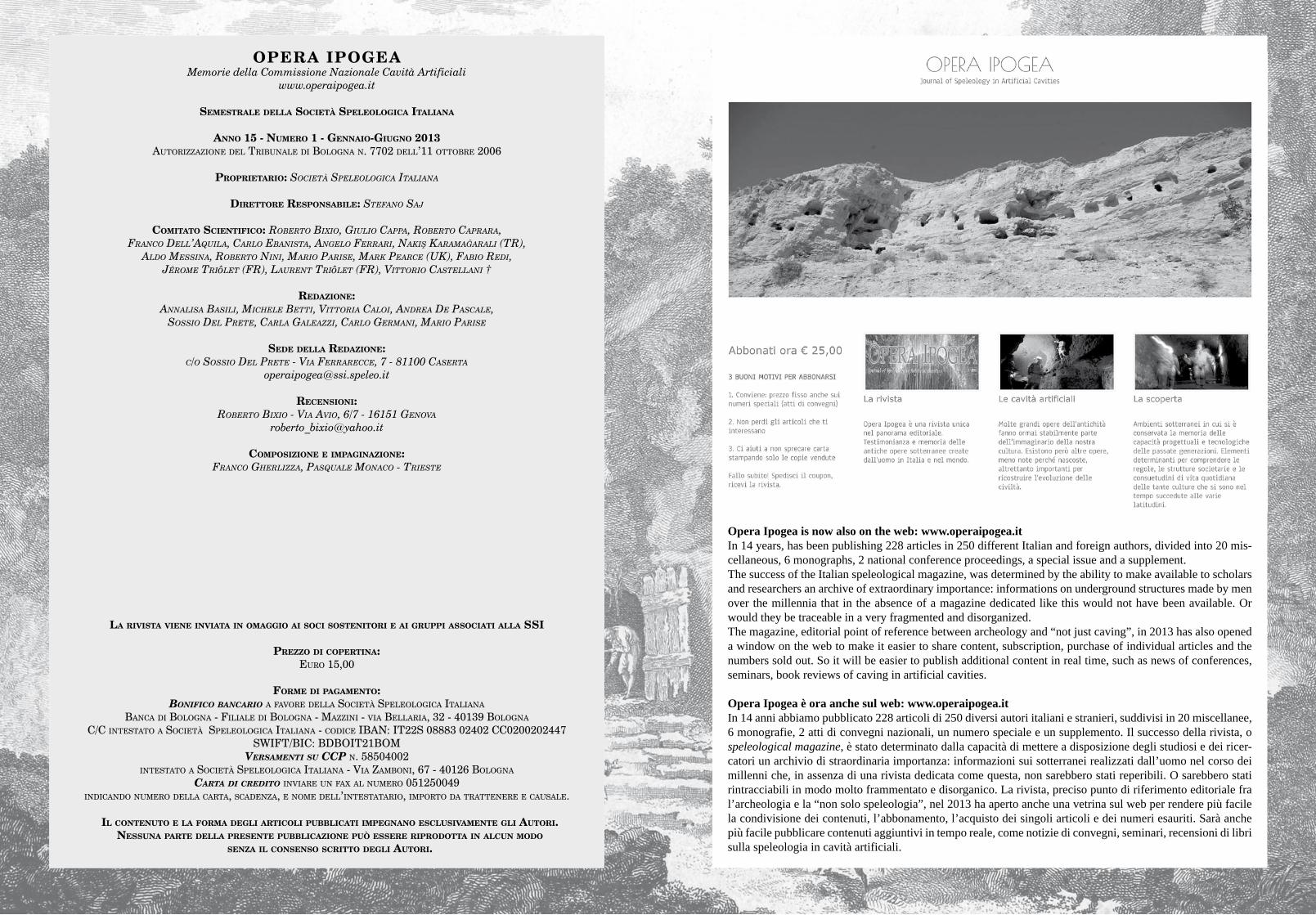
OPERA IPOGEAMemorie della Commissione Nazionale Cavità Artificiali
www.operaipogea.it
SemeStrale della Società Speleologica italiana
anno 15 - numero 1 - gennaio-giugno 2013AutorizzAzione del tribunAle di bolognA n. 7702 dell’11 ottobre 2006
proprietario: Società Speleologica italiana
direttore reSponSabile: Stefano Saj
comitato Scientifico: RobeRto bixio, giulio cappa, RobeRto capRaRa,Franco Dell’aquila, carlo ebanista, angelo Ferrari, nakiş karamağarali (tr),
alDo messina, roberto nini, mario Parise, mark Pearce (uk), Fabio reDi,Jérome triôlet (Fr), laurent triôlet (Fr), Vittorio castellani †
redazione:annalisa basili, michele betti, Vittoria caloi, anDrea De Pascale,
sossio Del Prete, carla galeazzi, carlo germani, mario Parise
Sede della redazione:c/o sossio Del Prete - Via Ferrarecce, 7 - 81100 caserta
recenSioni:roberto bixio - Via aVio, 6/7 - 16151 genoVa
compoSizione e impaginazione:Franco gherlizza, Pasquale monaco - trieste
la riviSta viene inviata in omaggio ai Soci SoStenitori e ai gruppi aSSociati alla SSi
prezzo di copertina:euro 15,00
forme di pagamento:Bonifico Bancario A fAvore dellA Società SpeleologicA itAliAnA
bAncA di bolognA - filiAle di bolognA - MAzzini - viA bellAriA, 32 - 40139 bolognA
c/c inteStAto A Società SpeleologicA itAliAnA - codice ibAn: it22S 08883 02402 cc0200202447SWift/bic: bdboit21boM
Versamenti su ccP n. 58504002 inteStAto A Società SpeleologicA itAliAnA - viA zAMboni, 67 - 40126 bolognA
carta di credito inviAre un fAx Al nuMero 051250049indicAndo nuMero dellA cArtA, ScAdenzA, e noMe dell’inteStAtArio, iMporto dA trAttenere e cAuSAle.
il contenuto e la forma degli articoli pubblicati impegnano eScluSivamente gli autori. neSSuna parte della preSente pubblicazione può eSSere riprodotta in alcun modo
Senza il conSenSo Scritto degli autori.
Opera Ipogea is now also on the web: www.operaipogea.itIn 14 years, has been publishing 228 articles in 250 different Italian and foreign authors, divided into 20 mis-cellaneous, 6 monographs, 2 national conference proceedings, a special issue and a supplement.The success of the Italian speleological magazine, was determined by the ability to make available to scholars and researchers an archive of extraordinary importance: informations on underground structures made by men over the millennia that in the absence of a magazine dedicated like this would not have been available. Or would they be traceable in a very fragmented and disorganized.The magazine, editorial point of reference between archeology and “not just caving”, in 2013 has also opened a window on the web to make it easier to share content, subscription, purchase of individual articles and the numbers sold out. So it will be easier to publish additional content in real time, such as news of conferences, seminars, book reviews of caving in artificial cavities.
Opera Ipogea è ora anche sul web: www.operaipogea.itIn 14 anni abbiamo pubblicato 228 articoli di 250 diversi autori italiani e stranieri, suddivisi in 20 miscellanee, 6 monografie, 2 atti di convegni nazionali, un numero speciale e un supplemento. Il successo della rivista, o speleological magazine, è stato determinato dalla capacità di mettere a disposizione degli studiosi e dei ricer-catori un archivio di straordinaria importanza: informazioni sui sotterranei realizzati dall’uomo nel corso dei millenni che, in assenza di una rivista dedicata come questa, non sarebbero stati reperibili. O sarebbero stati rintracciabili in modo molto frammentato e disorganico. La rivista, preciso punto di riferimento editoriale fra l’archeologia e la “non solo speleologia”, nel 2013 ha aperto anche una vetrina sul web per rendere più facile la condivisione dei contenuti, l’abbonamento, l’acquisto dei singoli articoli e dei numeri esauriti. Sarà anche più facile pubblicare contenuti aggiuntivi in tempo reale, come notizie di convegni, seminari, recensioni di libri sulla speleologia in cavità artificiali.