Embed Size (px)
Citation preview
®
Operating and MaintenanceFor Petroleum Meters
M203Rev. AP.D. Oscillating Piston Flowmeters:
11⁄4″ Type 4 Petroleum 11⁄2″ Type 4 Petroleum
TABLE OF CONTENTS
Installation ................................................................................................................1
Operation .................................................................................................................3
Preset Models ..........................................................................................................3
Printer Register Models ...........................................................................................4
Calibration ................................................................................................................4
Register Maintenance ..............................................................................................5
11⁄4 Preset Models with Auto Stop Valve ...................................................................6
11⁄2 Preset Models with Auto Stop Valve ...................................................................7
Measuring Chamber Maintenance .........................................................................10
Gear Train Maintenance .........................................................................................12
Air Release Maintenance .......................................................................................12
General Maintenance .............................................................................................14
Troubleshooting ......................................................................................................15
INSTALLATIONUse pipe thread cement on the outside of male threads only.
The flowmeter may be located at any convenient point on the discharge line from the pump. OnPreset Models the base of the flowmeter casing is above the bottom of the valve. Do not clamp it inposition without using the spacers provided or making a hole for the valve.
Be sure to allow room for the removal of the strainer basket, register, and air release mecha-nism. (See Figure 15.)
The piping on the outlet side of the flowmeter should be arranged so as to eliminate the possi-bility of draining the measuring chamber.
All piping connected to the flowmeter must be firmly secured to prevent strain on the flowmetercasing. The use of flexible connections to the pump or tank is recommended.
There must be no bypass connection around the flowmeter. Experience has shown that thevalve in this line will eventually leak, work open or be accidentally left open.
In order to obtain a maximum rate of delivery, the compartment outlets and the piping should beas large as practical and the number of elbows should be reduced to a minimum. Sweep elbowsshould be used wherever possible.
Blowing The Hose: As it is impossible to blow all the liquid from the hose, the amount of liquid leftin the lines on the discharge side of the flowmeter will not be the same before and after everydelivery. It is therefore recommended that provision be made to keep the hose and outlet piping fullof liquid at all times. For this purpose a hose nozzle with a check valve should be used.
Pumping Out Underground Tanks: In making provisions for pumping out underground tanks, DONOT provide any connection between the outlet of the flowmeter and the compartments or manifold.A valve in this line which is leaky or carelessly left open will allow part of the metered liquid to bediverted.
Air Vent Line: The vent pipe from the air release should be 3⁄4″ pipe or 1⁄2″ inside diameter tubing.Care should be taken to prevent any possible obstruction to the free flow of air through this line.
It should either be connected to the top of one of the compartments or run into a container ofabout 5 gallons capacity to collect any liquid discharged with the air.
INSTALLATION
Piping
Page 1
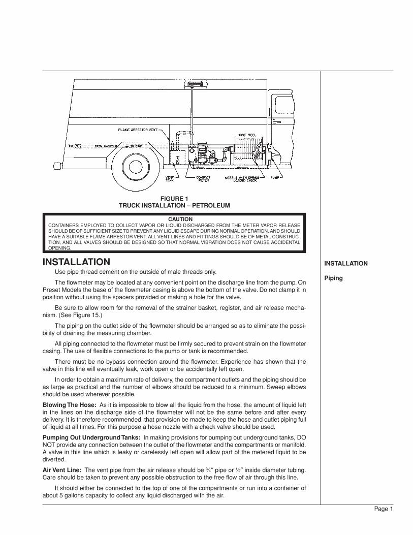
FIGURE 1TRUCK INSTALLATION – PETROLEUM
CAUTIONCONTAINERS EMPLOYED TO COLLECT VAPOR OR LIQUID DISCHARGED FROM THE METER VAPOR RELEASESHOULD BE OF SUFFICIENT SIZE TO PREVENT ANY LIQUID ESCAPE DURING NORMAL OPERATION, AND SHOULDHAVE A SUITABLE FLAME ARRESTOR VENT. ALL VENT LINES AND FITTINGS SHOULD BE OF METAL CONSTRUC-TION, AND ALL VALVES SHOULD BE DESIGNED SO THAT NORMAL VIBRATION DOES NOT CAUSE ACCIDENTALOPENING.
Interlocking OfCompartment OrManifold Valves
When Installing
After Installing
Cleaning The Strainer
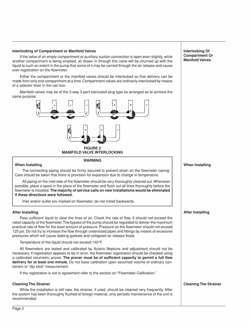
Interlocking of Compartment or Manifold Valves
If the valve of an empty compartment or auxiliary suction connection is open even slightly, whileanother compartment is being emptied, air drawn in through this valve will be churned up with theliquid to such an extent in the pump that some of it may be carried through the air release and causeover-registration on the flowmeter.
Either the compartment or the manifold valves should be interlocked so that delivery can bemade from only one compartment at a time. Compartment valves are ordinarily interlocked by meansof a selector lever in the can box.
Manifold valves may be of the 2-way 3-port lubricated plug type so arranged as to achieve thesame purpose.
FIGURE 2MANIFOLD VALVE INTERLOCKING
WARNINGWhen Installing
The connecting piping should be firmly secured to prevent strain on the flowmeter casing.Care should be taken that there is provision for expansion due to change in temperature.
All piping on the inlet side of the flowmeter should be very thoroughly cleaned out. Wheneverpossible, place a spool in the place of the flowmeter and flush out all lines thoroughly before theflowmeter is installed. The majority of service calls on new installations would be eliminatedif these directions were followed.
Inlet and/or outlet are marked on flowmeter; do not install backwards.
After Installing
Pass sufficient liquid to clear the lines of air. Check the rate of flow. It should not exceed therated capacity of the flowmeter. The bypass of the pump should be regulated to deliver the maximumpractical rate of flow for the least amount of pressure. Pressure on the flowmeter should not exceed125 psi. Do not try to increase the flow through undersized pipes and fittings by means of excessivepressures which will cause leaking gaskets and collapsed air release floats.
Temperature of the liquid should not exceed 140°F.
All flowmeters are tested and calibrated by Actaris Neptune and adjustment should not benecessary. If registration appears to be in error, the flowmeter registration should be checked usinga calibrated volumetric prover. The prover must be of sufficient capacity to permit a full flowdelivery for at least one minute. Do not base calibration upon assumed volume of ordinary con-tainers or “dip stick” measurement.
If the registration is not in agreement refer to the section on “Flowmeter Calibration.”
Cleaning The Strainer
While the installation is still new, the strainer, if used, should be cleaned very frequently. Afterthe system has been thoroughly flushed of foreign material, only periodic maintenance of the unit isrecommended.
Page 2
OPERATION
To Operate theFlowmeter
PRESET MODELS
To Stop In Emergency
To Adjust TrippingPoint
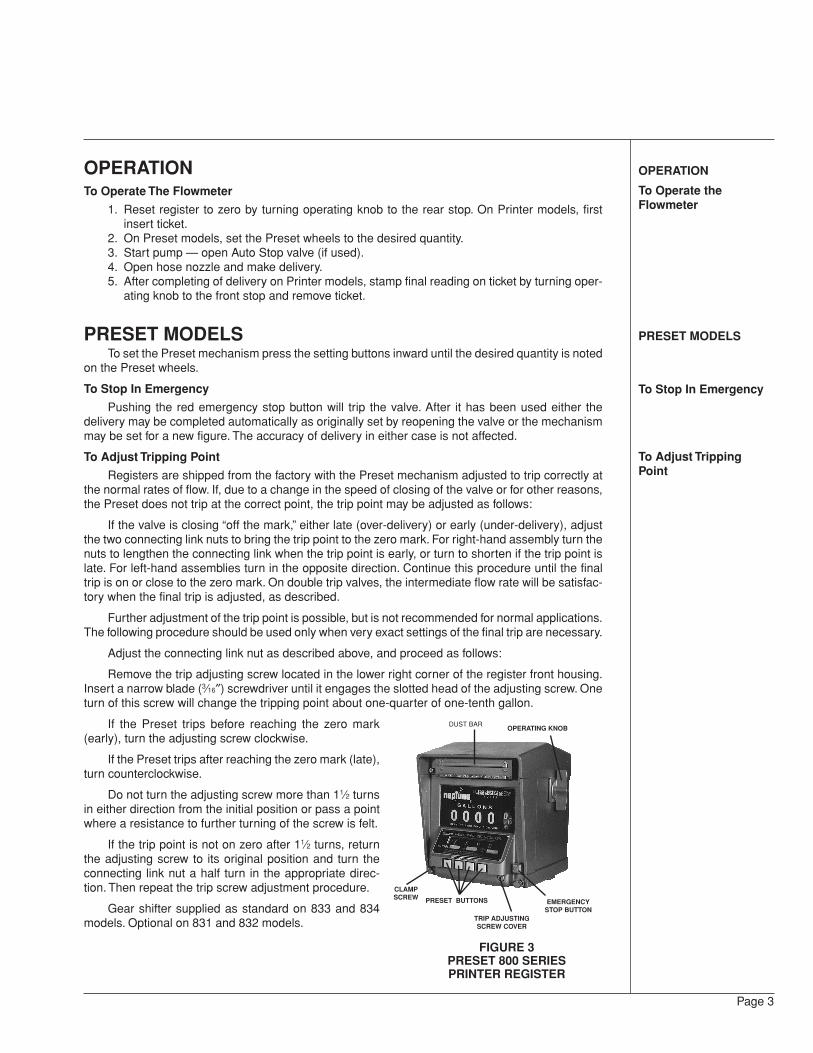
FIGURE 3PRESET 800 SERIESPRINTER REGISTER
Page 3
OPERATIONTo Operate The Flowmeter
1. Reset register to zero by turning operating knob to the rear stop. On Printer models, firstinsert ticket.
2. On Preset models, set the Preset wheels to the desired quantity.3. Start pump — open Auto Stop valve (if used).4. Open hose nozzle and make delivery.5. After completing of delivery on Printer models, stamp final reading on ticket by turning oper-
ating knob to the front stop and remove ticket.
PRESET MODELSTo set the Preset mechanism press the setting buttons inward until the desired quantity is noted
on the Preset wheels.
To Stop In Emergency
Pushing the red emergency stop button will trip the valve. After it has been used either thedelivery may be completed automatically as originally set by reopening the valve or the mechanismmay be set for a new figure. The accuracy of delivery in either case is not affected.
To Adjust Tripping Point
Registers are shipped from the factory with the Preset mechanism adjusted to trip correctly atthe normal rates of flow. If, due to a change in the speed of closing of the valve or for other reasons,the Preset does not trip at the correct point, the trip point may be adjusted as follows:
If the valve is closing “off the mark,” either late (over-delivery) or early (under-delivery), adjustthe two connecting link nuts to bring the trip point to the zero mark. For right-hand assembly turn thenuts to lengthen the connecting link when the trip point is early, or turn to shorten if the trip point islate. For left-hand assemblies turn in the opposite direction. Continue this procedure until the finaltrip is on or close to the zero mark. On double trip valves, the intermediate flow rate will be satisfac-tory when the final trip is adjusted, as described.
Further adjustment of the trip point is possible, but is not recommended for normal applications.The following procedure should be used only when very exact settings of the final trip are necessary.
Adjust the connecting link nut as described above, and proceed as follows:
Remove the trip adjusting screw located in the lower right corner of the register front housing.Insert a narrow blade (3⁄16″) screwdriver until it engages the slotted head of the adjusting screw. Oneturn of this screw will change the tripping point about one-quarter of one-tenth gallon.
If the Preset trips before reaching the zero mark(early), turn the adjusting screw clockwise.
If the Preset trips after reaching the zero mark (late),turn counterclockwise.
Do not turn the adjusting screw more than 11⁄2 turnsin either direction from the initial position or pass a pointwhere a resistance to further turning of the screw is felt.
If the trip point is not on zero after 11⁄2 turns, returnthe adjusting screw to its original position and turn theconnecting link nut a half turn in the appropriate direc-tion. Then repeat the trip screw adjustment procedure.
Gear shifter supplied as standard on 833 and 834models. Optional on 831 and 832 models.
DUST BAR
CLAMPSCREW
OPERATING KNOB
PRESET BUTTONS
TRIP ADJUSTINGSCREW COVER
EMERGENCYSTOP BUTTON
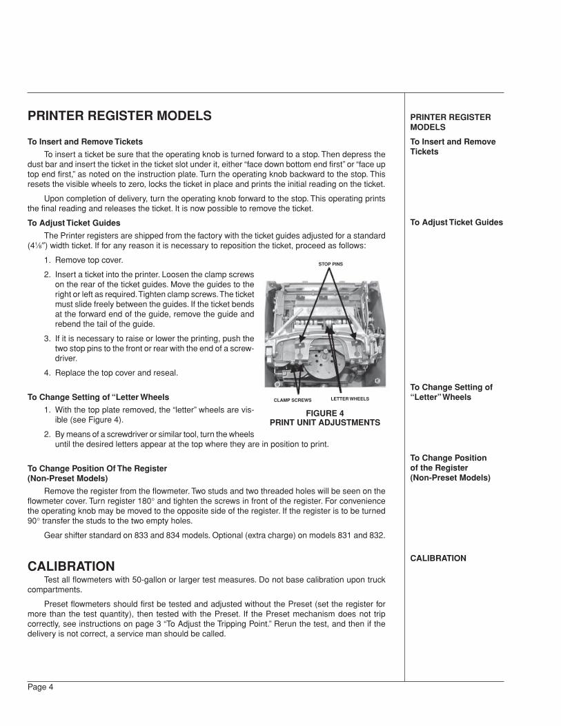
STOP PINS
CLAMP SCREWS LETTER WHEELS
FIGURE 4PRINT UNIT ADJUSTMENTS
PRINTER REGISTERMODELS
To Insert and RemoveTickets
To Adjust Ticket Guides
To Change Setting of“Letter” Wheels
To Change Positionof the Register(Non-Preset Models)
CALIBRATION
Page 4
PRINTER REGISTER MODELS
To Insert and Remove Tickets
To insert a ticket be sure that the operating knob is turned forward to a stop. Then depress thedust bar and insert the ticket in the ticket slot under it, either “face down bottom end first” or “face uptop end first,” as noted on the instruction plate. Turn the operating knob backward to the stop. Thisresets the visible wheels to zero, locks the ticket in place and prints the initial reading on the ticket.
Upon completion of delivery, turn the operating knob forward to the stop. This operating printsthe final reading and releases the ticket. It is now possible to remove the ticket.
To Adjust Ticket Guides
The Printer registers are shipped from the factory with the ticket guides adjusted for a standard(41⁄8″) width ticket. If for any reason it is necessary to reposition the ticket, proceed as follows:
1. Remove top cover.
2. Insert a ticket into the printer. Loosen the clamp screwson the rear of the ticket guides. Move the guides to theright or left as required. Tighten clamp screws. The ticketmust slide freely between the guides. If the ticket bendsat the forward end of the guide, remove the guide andrebend the tail of the guide.
3. If it is necessary to raise or lower the printing, push thetwo stop pins to the front or rear with the end of a screw-driver.
4. Replace the top cover and reseal.
To Change Setting of “Letter Wheels
1. With the top plate removed, the “letter” wheels are vis-ible (see Figure 4).
2. By means of a screwdriver or similar tool, turn the wheelsuntil the desired letters appear at the top where they are in position to print.
To Change Position Of The Register(Non-Preset Models)
Remove the register from the flowmeter. Two studs and two threaded holes will be seen on theflowmeter cover. Turn register 180° and tighten the screws in front of the register. For conveniencethe operating knob may be moved to the opposite side of the register. If the register is to be turned90° transfer the studs to the two empty holes.
Gear shifter standard on 833 and 834 models. Optional (extra charge) on models 831 and 832.
CALIBRATIONTest all flowmeters with 50-gallon or larger test measures. Do not base calibration upon truck
compartments.
Preset flowmeters should first be tested and adjusted without the Preset (set the register formore than the test quantity), then tested with the Preset. If the Preset mechanism does not tripcorrectly, see instructions on page 3 “To Adjust the Tripping Point.” Rerun the test, and then if thedelivery is not correct, a service man should be called.
Erratic Registration
Erratic registration is an indication of trouble in the system caused by air or dirt in the measuringchamber. Do not try to correct this by recalibration of the flowmeter, but first check over the piping forair leaks, clean the strainer and then, if the trouble has not been found, clean the flowmeter asdirected on pages 10 and 11. If this does not correct the trouble, check for faulty installation.
Over-registration is an indication of air, whereas under-registration is generally caused by dirt orpipe scale in the measuring chamber, or the liquid bypassing the flowmeter in some manner.
Consistent Over or Under-Registration
When the flowmeter registers consistently either more or less than is delivered, the calibrationmay be corrected in the following manner:
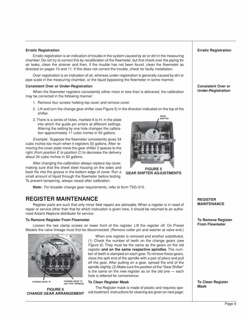
1. Remove four screws holding top cover and remove cover.
2. Lift and turn the change gear shifter (see Figure 5) in the direction indicated on the top of theshifter.
3. There is a series of holes, marked A to H, in the plateinto which the guide pin enters at different settings.Altering the setting by one hole changes the calibra-tion approximately 17 cubic inches in 50 gallons.
Example: Suppose the flowmeter consistently gives 34cubic inches too much when it registers 50 gallons. After re-moving the cover plate move the gear shifter 2 spaces to theright (from position E to position C) to decrease the deliveryabout 34 cubic inches in 50 gallons.
After changing the calibration always replace top cover,making sure that the sheet steel housing on the sides andback fits into the groove in the bottom edge of cover. Run asmall amount of liquid through the flowmeter before testing.To prevent tampering, always reseal after calibration.
Note: For broader change gear requirements, refer to form TSG-310.
REGISTER MAINTENANCERegister parts are such that only minor field repairs are advisable. When a register is in need of
repair or service other than that for which instruction is given here, it should be returned to an autho-rized Actaris Neptune distributor for service.
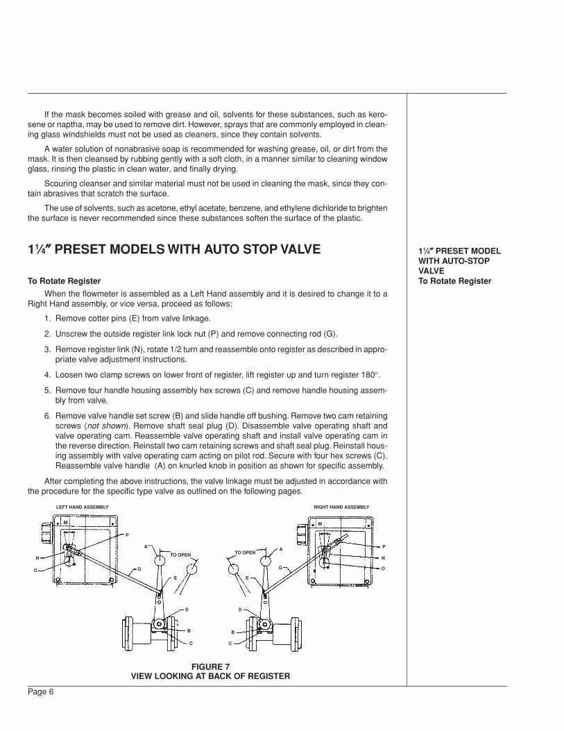
To Remove Register From Flowmeter
Loosen the two clamp screws on lower front of the register. Lift the register off. On PresetModels the valve linkage must first be disconnected. (Remove cotter pin and washer at valve end.)
When one register is removed and another substituted,(1) Check the number of teeth on the change gears (seeFigure 6). They must be the same as the gears on the oldregister and on the same respective spindles. The num-ber of teeth is stamped on each gear. To remove these gears,close the split end of the spindle with a pair of pliers and pulloff the gear. After putting on a gear, spread the end of thespindle slightly. (2) Make sure the position of the “Gear Shifter”is the same on the new register as on the old one — eachhole is lettered for convenience.
To Clean Register Mask
The Register mask is made of plastic and requires spe-cial treatment. Instructions for cleaning are given on next page:
Erratic Registration
Consistent Over orUnder-Registration
REGISTERMAINTENANCE
To Remove RegisterFrom Flowmeter
To Clean RegisterMask
Page 5
FIGURE 6CHANGE GEAR ARRANGEMENT
CHANGE GEAR “R” CHANGE GEAR “S”(ON “STD” SPINDLE)
GEARSHIFTER
FIGURE 5GEAR SHIFTER ADJUSTMENTS
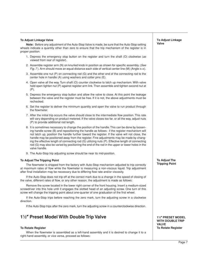
RIGHT HAND ASSEMBLY
M
P
N
O
A
G
E
D
B
C
TO OPENTO OPEN
A
G
E
D
B
C
M
P
N
O
11⁄4″″″″″ PRESET MODELWITH AUTO-STOPVALVETo Rotate Register
Page 6
If the mask becomes soiled with grease and oil, solvents for these substances, such as kero-sene or naptha, may be used to remove dirt. However, sprays that are commonly employed in clean-ing glass windshields must not be used as cleaners, since they contain solvents.
A water solution of nonabrasive soap is recommended for washing grease, oil, or dirt from themask. It is then cleansed by rubbing gently with a soft cloth, in a manner similar to cleaning windowglass, rinsing the plastic in clean water, and finally drying.
Scouring cleanser and similar material must not be used in cleaning the mask, since they con-tain abrasives that scratch the surface.
The use of solvents, such as acetone, ethyl acetate, benzene, and ethylene dichloride to brightenthe surface is never recommended since these substances soften the surface of the plastic.
11⁄4″″″″″ PRESET MODELS WITH AUTO STOP VALVE
To Rotate Register
When the flowmeter is assembled as a Left Hand assembly and it is desired to change it to aRight Hand assembly, or vice versa, proceed as follows:
1. Remove cotter pins (E) from valve linkage.
2. Unscrew the outside register link lock nut (P) and remove connecting rod (G).
3. Remove register link (N), rotate 1/2 turn and reassemble onto register as described in appro-priate valve adjustment instructions.
4. Loosen two clamp screws on lower front of register, lift register up and turn register 180°.
5. Remove four handle housing assembly hex screws (C) and remove handle housing assem-bly from valve.
6. Remove valve handle set screw (B) and slide handle off bushing. Remove two cam retainingscrews (not shown). Remove shaft seal plug (D). Disassemble valve operating shaft andvalve operating cam. Reassemble valve operating shaft and install valve operating cam inthe reverse direction. Reinstall two cam retaining screws and shaft seal plug. Reinstall hous-ing assembly with valve operating cam acting on pilot rod. Secure with four hex screws (C).Reassemble valve handle (A) on knurled knob in position as shown for specific assembly.
After completing the above instructions, the valve linkage must be adjusted in accordance withthe procedure for the specific type valve as outlined on the following pages.
FIGURE 7VIEW LOOKING AT BACK OF REGISTER
LEFT HAND ASSEMBLY
To Adjust LinkageValve
To Adjust TheTripping Point
11⁄2″″″″″ PRESET MODELWITH DOUBLE TRIPVALVETo Rotate Register
Page 7
To Adjust Linkage Valve
Note: Before any adjustment of the Auto-Stop Valve is made, be sure that the Auto-Stop settingwheels indicate a quantity other than zero to ensure that the trip mechanism of the register is inproper position.
1. Depress the emergency stop button on the register and turn the shaft (O) clockwise (asviewed from rear of register).
2. Assemble register arm (N) on knurled knob in position as shown for specific assembly. (SeeFig. 7 ). Arm should move an equal distance each side of vertical center line (M) (Angle x=x).
3. Assemble one nut (P) on connecting rod (G) and the other end of the connecting rod to thecenter hole in handle (A) using washers and cotter pins (E).
4. Open valve all the way. Turn shaft (O) counter clockwise to latch up mechanism. With valveheld open tighten nut (P) against register arm link. Then assemble and tighten second nut at(P).
5. Depress the emergency stop button and allow the valve to close. At this point the leakagebetween the valve and the register must be free. If it is not, the above adjustments must berechecked.
6. Set the register to deliver the minimum quantity and open the valve to run product throughthe flowmeter.
7. After the initial trip occurs the valve should close to the intermediate flow position. This ratewill vary depending on product metered. If the valve closes too far, or all the way, adjust nuts(P) to provide additional rod length.
8. It is sometimes necessary to change the position of the handle. This can be done by loosen-ing handle screw (B) and repositioning the handle as follows: if the register mechanism willnot latch up, position the handle further toward the register. If the valve will not close, thehandle may be positioned away from the register. Fine adjustments may be made by chang-ing the effective length of connecting rod (G) utilizing nuts (P). Effective length of connectingrod (G) may also be varied by positioning the end of the rod in the upper or lower holes in thevalve handle.
9. The Auto-Stop trip adjusting screw should be near its mid-position.
To Adjust The Tripping Point
The flowmeter is shipped from the factory with Auto-Stop mechanism adjusted to trip correctlyat maximum rates of flow while the flowmeter is measuring a non-viscous liquid. Trip adjustmentafter final installation may be necessary due to differing flow rate and/or viscosity.
If the Auto-Stop does not trip off at the correct mark due to a change in the speed of closing ofthe valve, different rates of flow, or any other reason, the adjustment is made as follows:
Remove the screw located in the lower right corner of the front housing. Insert a medium-sizedscrewdriver into this hole until it engages the slotted head of an adjusting screw. One turn of thisscrew will change the tripping point about one-quarter of one graduation of the first wheel.
If the Auto-Stop trips before reaching the zero mark, turn the adjusting screw in a clockwisedirection.
If the Auto-Stop trips after the zero mark, turn the adjusting screw in a counterclockwise direction.
11⁄2″″″″″ Preset Model With Double Trip Valve
To Rotate Register
When the flowmeter is assembled as a left-hand assembly and it is desired to change it to aright-hand assembly, or vice versa, proceed as follows:
Adjustment of Auto-Stop Valve
To Adjust Valve Linkage
Page 8
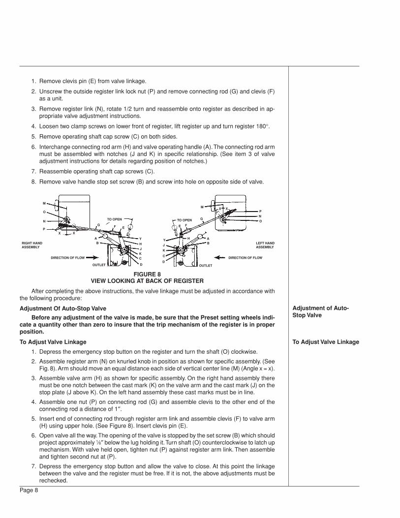
1. Remove clevis pin (E) from valve linkage.
2. Unscrew the outside register link lock nut (P) and remove connecting rod (G) and clevis (F)as a unit.
3. Remove register link (N), rotate 1/2 turn and reassemble onto register as described in ap-propriate valve adjustment instructions.
4. Loosen two clamp screws on lower front of register, lift register up and turn register 180°.
5. Remove operating shaft cap screw (C) on both sides.
6. Interchange connecting rod arm (H) and valve operating handle (A). The connecting rod armmust be assembled with notches (J and K) in specific relationship. (See item 3 of valveadjustment instructions for details regarding position of notches.)
7. Reassemble operating shaft cap screws (C).
8. Remove valve handle stop set screw (B) and screw into hole on opposite side of valve.
FIGURE 8VIEW LOOKING AT BACK OF REGISTER
After completing the above instructions, the valve linkage must be adjusted in accordance withthe following procedure:
Adjustment Of Auto-Stop Valve
Before any adjustment of the valve is made, be sure that the Preset setting wheels indi-cate a quantity other than zero to insure that the trip mechanism of the register is in properposition.
To Adjust Valve Linkage
1. Depress the emergency stop button on the register and turn the shaft (O) clockwise.
2. Assemble register arm (N) on knurled knob in position as shown for specific assembly. (SeeFig. 8). Arm should move an equal distance each side of vertical center line (M) (Angle x = x).
3. Assemble valve arm (H) as shown for specific assembly. On the right hand assembly theremust be one notch between the cast mark (K) on the valve arm and the cast mark (J) on thestop plate (J above K). On the left hand assembly these cast marks must be in line.
4. Assemble one nut (P) on connecting rod (G) and assemble clevis to the other end of theconnecting rod a distance of 1″.
5. Insert end of connecting rod through register arm link and assemble clevis (F) to valve arm(H) using upper hole. (See Figure 8). Insert clevis pin (E).
6. Open valve all the way. The opening of the valve is stopped by the set screw (B) which shouldproject approximately 1⁄8″ below the lug holding it. Turn shaft (O) counterclockwise to latch upmechanism. With valve held open, tighten nut (P) against register arm link. Then assembleand tighten second nut at (P).
7. Depress the emergency stop button and allow the valve to close. At this point the linkagebetween the valve and the register must be free. If it is not, the above adjustments must berechecked.
M
O
N
PX X
G
TO OPEN
F E
AB
DIRECTION OF FLOW
Y
H
JKC
DOUTLET
RIGHT HANDASSEMBLY
M
O
N
PX X
GTO OPEN
FE
AB
DIRECTION OF FLOW
Y H
J
K
C
DOUTLET
LEFT HANDASSEMBLY
DOUBLE TRIPMAINTENANCE
To Disassemble andAssemble Double TripValve
Page 9
8. Set the register to deliver the minimum quantity and open the valve to run product throughthe flowmeter.
9. After the initial trip occurs the valve should close to the intermediate flow position. This rateshould be approximately 15 to 20 gpm. If the valve closes too far, or all the way, unscrewclevis (F) on rod (G) to hold valve open further. If the rate of flow is too fast during theintermediate position, turn the clevis onto the rod to allow the valve to close further. Itshould not be necessary to turn more than one turn in either direction.
10. It is sometimes necessary to change the position of set screw (B) if the clevis has beenreadjusted. If the register mechanism will not latch up, unscrew the set screw to allow thevalve to open further. If the connection rod (G) is under compression, when the valve is heldall the way open, turn the set screw down to relieve the pressure on the register.
11. The Auto-Stop trip adjusting screw should be near its mid-position. If a small adjustment ofthis screw will not permit the register to shut off “on the mark” it is usually possible to correctthis by a slight adjustment of the clevis (F). This will move the main valve nearer to or furtheraway from its seat during the intermediate flow and thereby change the amount of timeneeded for the valve to fully close at the last trip (Also see To Adjust The Tripping Point.)
NOTE: If it is difficult to obtain proper rate of flow during intermediate trip position and still haveregular latch up fully. Check Auto-Stop valve to insure that it is opening all the way. Check valve byremoving set screw (B) and clevis (F) from valve arm; open valve as far as possible. The distancebetween lug on arm and lug on stop plate must not be more than 1⁄4″.
DOUBLE TRIP MAINTENANCE
To Disassemble and Assemble Double Trip Valve
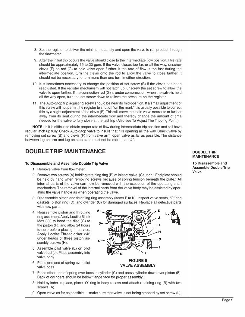
1. Remove valve from flowmeter.
2. Remove two screws (A) holding retaining ring (B) at inlet of valve. (Caution: End plate shouldbe held by hand when removing screws because of spring tension beneath the plate.) Allinternal parts of the valve can now be removed with the exception of the operating shaftmechanism. The removal of the internal parts from the valve body may be assisted by oper-ating the valve handle as when operating the valve.
3. Disassemble piston and throttling ring assembly (items F to K). Inspect valve seats, “O” ringgaskets, piston ring (D), and cylinder (C) for damaged surfaces. Replace all defective partswith new parts.
4. Reassemble piston and throttlingring assembly. Apply Loctite BlackMax 380 to bond the disc (G) tothe piston (F), and allow 24 hoursto cure before placing in service.Apply Loctite Threadlocker 242under heads of three piston as-sembly screws (H).
5. Assemble pilot valve (E) on pilotvalve rod (J). Place assembly intovalve body.
6. Place one end of spring over pilotvalve boss.
7. Place other end of spring over boss in cylinder (C) and press cylinder down over piston (F).Back of cylinders should be below flange face for proper assembly.
8. Hold cylinder in place, place “O” ring in body recess and attach retaining ring (B) with twoscrews (A).
9 Open valve as far as possible — make sure that valve is not being stopped by set screw (L).
FIGURE 9VALVE ASSEMBLY
To Adjust Rate ofClosing of Valve
To Inspect OperatingShaft Seals of PresetValves
MEASURING CHAMBERMAINTENANCE
To Remove AndDisassemble
Page 10
To Adjust Rate of Closing Of Valve
Variations in the viscosity of the liquids being measured will cause changes in the rate of closingof the valve from its full open position to its intermediate position. (Valve should reach its intermedi-ate position with approximately 4 gallons remaining on Preset setting wheels.)
Setting of orifice plate is indicated on tag attached to valve.
The rate of closing can be adjusted by changing the position of orifice plate which is readilyaccessible through inlet of valve. (Valve does not have to be disassembled.)
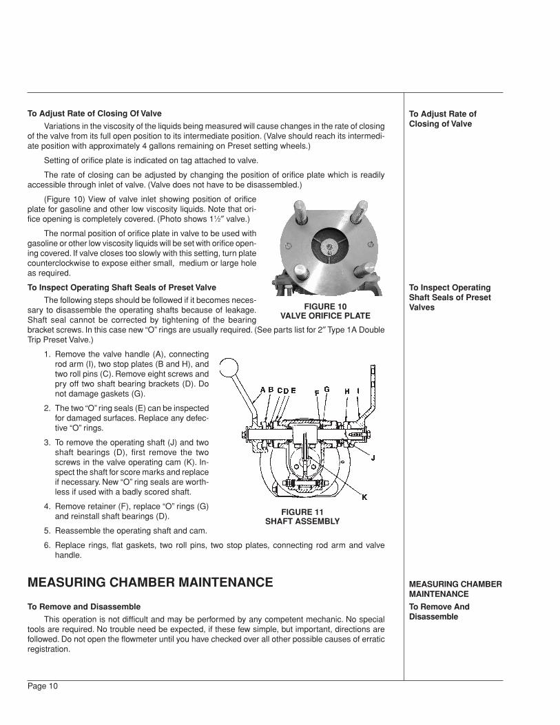
(Figure 10) View of valve inlet showing position of orificeplate for gasoline and other low viscosity liquids. Note that ori-fice opening is completely covered. (Photo shows 11⁄2″ valve.)
The normal position of orifice plate in valve to be used withgasoline or other low viscosity liquids will be set with orifice open-ing covered. If valve closes too slowly with this setting, turn platecounterclockwise to expose either small, medium or large holeas required.
To Inspect Operating Shaft Seals of Preset Valve
The following steps should be followed if it becomes neces-sary to disassemble the operating shafts because of leakage.Shaft seal cannot be corrected by tightening of the bearingbracket screws. In this case new “O” rings are usually required. (See parts list for 2″ Type 1A DoubleTrip Preset Valve.)
1. Remove the valve handle (A), connectingrod arm (I), two stop plates (B and H), andtwo roll pins (C). Remove eight screws andpry off two shaft bearing brackets (D). Donot damage gaskets (G).
2. The two “O” ring seals (E) can be inspectedfor damaged surfaces. Replace any defec-tive “O” rings.
3. To remove the operating shaft (J) and twoshaft bearings (D), first remove the twoscrews in the valve operating cam (K). In-spect the shaft for score marks and replaceif necessary. New “O” ring seals are worth-less if used with a badly scored shaft.
4. Remove retainer (F), replace “O” rings (G)and reinstall shaft bearings (D).
5. Reassemble the operating shaft and cam.
6. Replace rings, flat gaskets, two roll pins, two stop plates, connecting rod arm and valvehandle.
MEASURING CHAMBER MAINTENANCE
To Remove and Disassemble
This operation is not difficult and may be performed by any competent mechanic. No specialtools are required. No trouble need be expected, if these few simple, but important, directions arefollowed. Do not open the flowmeter until you have checked over all other possible causes of erraticregistration.
FIGURE 11SHAFT ASSEMBLY
FIGURE 10VALVE ORIFICE PLATE
Page 11
1. Prepare a clean surface on which to place the parts as they are removed. The parts aremachined to close tolerances and should be handled with care. Have a replacement gasketready before opening the flowmeter.
2. Loosen the two clamp screws on the lower front of the register. Lift the register off. On PresetModels the valve linkage must first be disconnected. (Remove cotter pin and washer at valveend.)
3. Remove the flowmeter cover taking care not to damage the gasket.
4. Lift the measuring chamber from the flowmeter casing.
5. Remove the upper cylinder head by inserting a screwdriver in one of the slots provided andprying it off. Be careful not to scratch or nick any part of the chamber.
6. Lift out the piston by its spindle. If care is taken to draw it straight, it should come out easily.Do not force it.
7. Remove the control roller and the diaphragm from the lower cylinder head.
8. The seal pin may be removed (for replacement only) by pulling upward, using pliers if neces-sary.
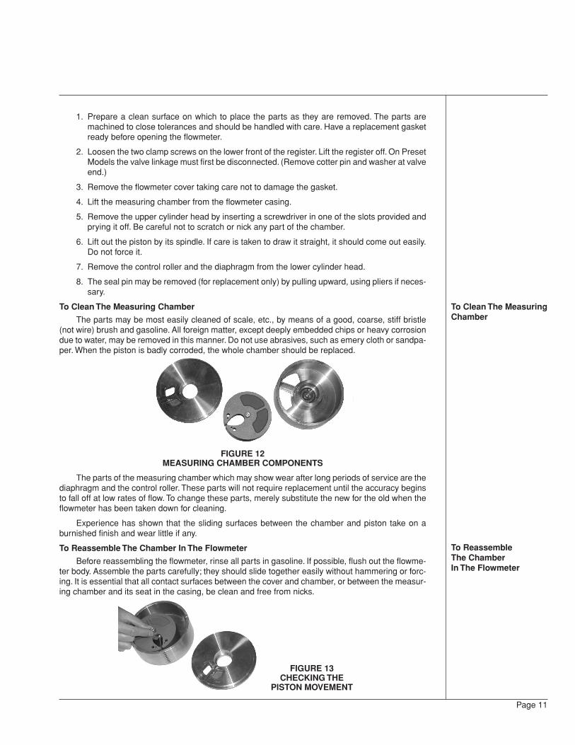
To Clean The Measuring Chamber
The parts may be most easily cleaned of scale, etc., by means of a good, coarse, stiff bristle(not wire) brush and gasoline. All foreign matter, except deeply embedded chips or heavy corrosiondue to water, may be removed in this manner. Do not use abrasives, such as emery cloth or sandpa-per. When the piston is badly corroded, the whole chamber should be replaced.
FIGURE 12MEASURING CHAMBER COMPONENTS
The parts of the measuring chamber which may show wear after long periods of service are thediaphragm and the control roller. These parts will not require replacement until the accuracy beginsto fall off at low rates of flow. To change these parts, merely substitute the new for the old when theflowmeter has been taken down for cleaning.
Experience has shown that the sliding surfaces between the chamber and piston take on aburnished finish and wear little if any.
To Reassemble The Chamber In The Flowmeter
Before reassembling the flowmeter, rinse all parts in gasoline. If possible, flush out the flowme-ter body. Assemble the parts carefully; they should slide together easily without hammering or forc-ing. It is essential that all contact surfaces between the cover and chamber, or between the measur-ing chamber and its seat in the casing, be clean and free from nicks.
To Clean The MeasuringChamber
To ReassembleThe ChamberIn The Flowmeter
FIGURE 13CHECKING THE
PISTON MOVEMENT
1. Assemble diaphragm and seal pin in chamber if replacement was necessary.
2. Place the control roller on its pin and see that it will rotate freely.
3. Replace the piston and oscillate it carefully by hand; it should move easily without binding. Ifit sticks, do not force it, but remove and locate the cause. Do not file down the roller as thiswill impair the accuracy of the flowmeter.
4. Replace the upper cylinder head and again oscillate the piston to make sure that is free.
5. When replacing the measuring chamber in the casing, be sure that the seat is clean and freefrom nicks. Make sure the dowel pin in the main casing enters the slot in the chamber bottomproperly and allows the chamber to rest on its seat.
6. Before replacing the cover, first be sure the chamber is properly seated and inspect thegasket. Then set the arm of the gear train so that it will not come down on the piston spindle.
7. Make sure the cover is down on its seat before tightening the bolts.
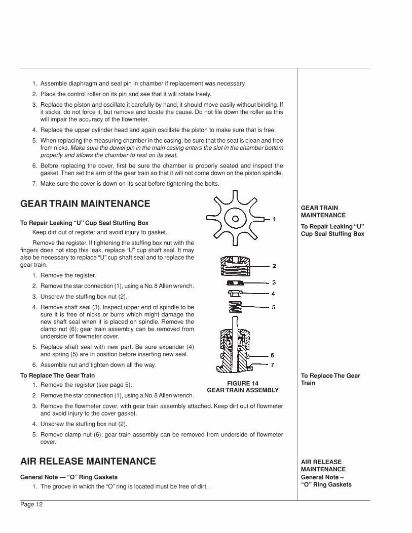
GEAR TRAIN MAINTENANCE
To Repair Leaking “U” Cup Seal Stuffing Box
Keep dirt out of register and avoid injury to gasket.
Remove the register. If tightening the stuffing box nut with thefingers does not stop this leak, replace “U” cup shaft seal. It mayalso be necessary to replace “U” cup shaft seal and to replace thegear train.
1. Remove the register.
2. Remove the star connection (1), using a No. 8 Allen wrench.
3. Unscrew the stuffing box nut (2).
4. Remove shaft seal (3). Inspect upper end of spindle to besure it is free of nicks or burrs which might damage thenew shaft seal when it is placed on spindle. Remove theclamp nut (6); gear train assembly can be removed fromunderside of flowmeter cover.
5. Replace shaft seal with new part. Be sure expander (4)and spring (5) are in position before inserting new seal.
6. Assemble nut and tighten down all the way.
To Replace The Gear Train
1. Remove the register (see page 5).
2. Remove the star connection (1), using a No. 8 Allen wrench.
3. Remove the flowmeter cover, with gear train assembly attached. Keep dirt out of flowmeterand avoid injury to the cover gasket.
4. Unscrew the stuffing box nut (2).
5. Remove clamp nut (6); gear train assembly can be removed from underside of flowmetercover.
AIR RELEASE MAINTENANCE
General Note — “O” Ring Gaskets
1. The groove in which the “O” ring is located must be free of dirt.
Page 12
GEAR TRAINMAINTENANCE
To Repair Leaking “U”Cup Seal Stuffing Box
To Replace The GearTrain
AIR RELEASEMAINTENANCEGeneral Note –“O” Ring Gaskets
FIGURE 14GEAR TRAIN ASSEMBLY
Page 13
To Clean The Strainer
Air Release ValveTroubles
To Inspect Air ReleaseUnit
2. The flat face against which the “O” ring seats must be clean and free of nicks or dents whichwill allow the pressure to leak between the gasket and the metal.
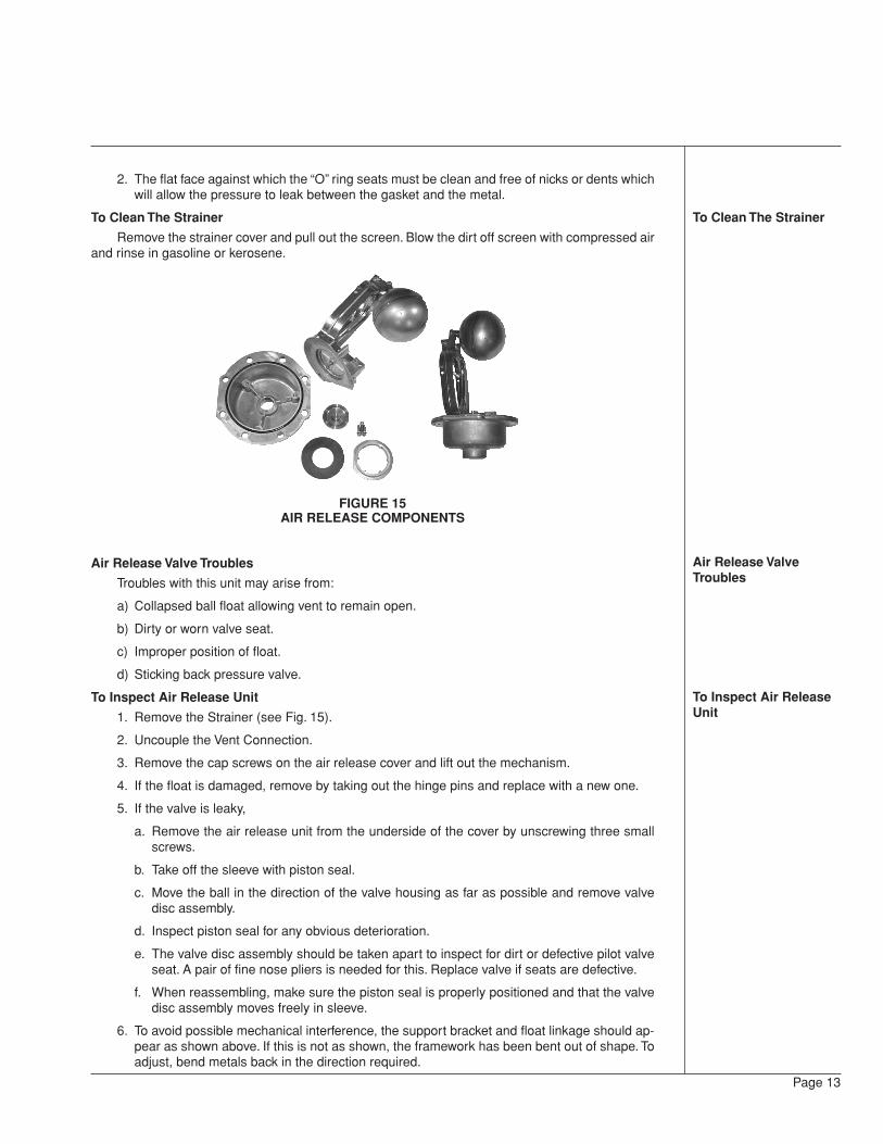
To Clean The Strainer
Remove the strainer cover and pull out the screen. Blow the dirt off screen with compressed airand rinse in gasoline or kerosene.
FIGURE 15AIR RELEASE COMPONENTS
Air Release Valve Troubles
Troubles with this unit may arise from:
a) Collapsed ball float allowing vent to remain open.
b) Dirty or worn valve seat.
c) Improper position of float.
d) Sticking back pressure valve.
To Inspect Air Release Unit
1. Remove the Strainer (see Fig. 15).
2. Uncouple the Vent Connection.
3. Remove the cap screws on the air release cover and lift out the mechanism.
4. If the float is damaged, remove by taking out the hinge pins and replace with a new one.
5. If the valve is leaky,
a. Remove the air release unit from the underside of the cover by unscrewing three smallscrews.
b. Take off the sleeve with piston seal.
c. Move the ball in the direction of the valve housing as far as possible and remove valvedisc assembly.
d. Inspect piston seal for any obvious deterioration.
e. The valve disc assembly should be taken apart to inspect for dirt or defective pilot valveseat. A pair of fine nose pliers is needed for this. Replace valve if seats are defective.
f. When reassembling, make sure the piston seal is properly positioned and that the valvedisc assembly moves freely in sleeve.
6. To avoid possible mechanical interference, the support bracket and float linkage should ap-pear as shown above. If this is not as shown, the framework has been bent out of shape. Toadjust, bend metals back in the direction required.
Page 14
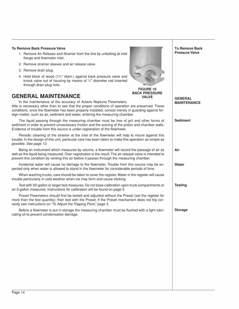
To Remove Back Pressure Valve
1. Remove Air Release and Strainer from the line by unbolting at inletflange and flowmeter inlet.
2. Remove strainer sleeves and air release valve.
3. Remove drain plug.
4. Hold block of wood (13⁄4″ diam.) against back pressure valve andknock valve out of housing by means of 1⁄2″ diameter rod insertedthrough drain plug hole.
GENERAL MAINTENANCEIn the maintenance of the accuracy of Actaris Neptune Flowmeters,
little is necessary other than to see that the proper conditions of operation are preserved. Theseconditions, once the flowmeter has been properly installed, consist merely in guarding against for-eign matter, such as air, sediment and water, entering the measuring chamber.
The liquid passing through the measuring chamber must be free of grit and other forms ofsediment in order to prevent unnecessary friction and the scoring of the piston and chamber walls.Evidence of trouble from this source is under-registration of the flowmeter.
Periodic cleaning of the strainer at the inlet of the flowmeter will help to insure against thistrouble. In the design of this unit, particular care has been taken to make this operation as simple aspossible. See page 13.
Being an instrument which measures by volume, a flowmeter will record the passage of air aswell as the liquid being measured. Over-registration is the result. The air release valve is intended toprevent this condition by venting this air before it passes through the measuring chamber.
Incidental water will cause no damage to the flowmeter. Trouble from this source may be ex-pected only when water is allowed to stand in the flowmeter for considerable periods of time.
When washing trucks, care should be taken to cover the register. Water in the register will causetrouble particularly in cold weather when ice may form and cause sticking.
Test with 50-gallon or larger test measures. Do not base calibration upon truck compartments oron 5-gallon measures. Instructions for calibration will be found on page 5.
Preset Flowmeters should first be tested and adjusted without the Preset (set the register formore than the test quantity); then test with the Preset. If the Preset mechanism does not trip cor-rectly see instructions on “To Adjust the Tripping Point,” page 3.
Before a flowmeter is put in storage the measuring chamber must be flushed with a light lubri-cating oil to prevent condensation damage.
To Remove BackPressure Valve
GENERALMAINTENANCE
Sediment
Air
Water
Testing
Storage
FIGURE 16BACK PRESSURE
VALVE
Page 15
TROUBLESHOOTINGTROUBLESHOOTING1. Register Not Working When Liquid is Flowing
a) Bypass around flowmeter not shut off.b) Frozen condensation inside register.c) Register in need of repair.d) Sheared key on “Change Gear” — caused by ice in register.
2. Leakage at the Stuffing Boxa) Loose stuffing box nut or worn spindle.
3. Chronic Leakage at the Main Case Gasketa) Excessive line or shock pressure.b) Broken gasket or loose bolts.
4. Reduction in the Rate or Complete Stoppage of Dischargea) Pump bypass stuck open.b) Air release valve fails to close allowing the liquid to escape through air vent.c) An open valve in the piping allowing liquid to circulate around the pump.d) Worn pump.e) Blocked strainer due to sediment or frost.f) Piston in flowmeter stuck, caused by dirt. Check strainer and clean measuring chamber.
5. Over-Registration — Erratica) Leaking valve in empty compartment causing an emulsion of air and oil.b) Air release valve jamming allowing air to pass through the flowmeterc) Spring in back pressure valve broken or valve stuck open.d) Vent line from the air release valve plugged causing air to pass through the flowmeter.e) Leaks in the suction line such as at valve stems, pump packing, or flange gaskets.f) Air pockets in closed-end piping in the suction line.g) Manifold or compartment valves only partly open causing excessive suction.h) Suction piping too small causing excessive suction.
6. Under-Registration — Erratica) Dirt in the measuring chamber.b) Badly worn control roller or diaphragm.c) Main casing distorted or damaged.d) Dirt under the seat of the measuring chamber at the outlet port (after cleaning).e) Leakage around the flowmeter due to partly open valve.
7. Consistent Over- or Under-Registrationa) Flowmeter in need of calibration.
8. Liquid Leaking Out the Air Release Venta) Improper operation.b) Worn, damaged or defective valve unit.
9. Printing Not Clear in Cold Weathera) Ticket carbon not suitable for cold weather use.
PRESET MODELS
10. Cut Off is Not Accuratea) Trip Adjustment
Page 16
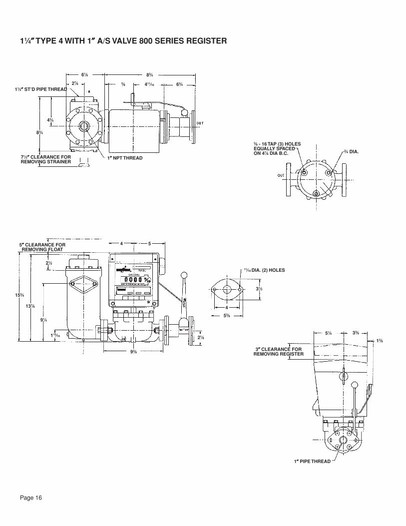
11⁄4″″″″″ TYPE 4 WITH 1″″″″″ A/S VALVE 800 SERIES REGISTER
11⁄2″″″″″ ST’D PIPE THREAD27⁄8
61⁄8
43⁄4
83⁄4
71⁄2″″″″″ CLEARANCE FORREMOVING STRAINER
1″″″″″ NPT THREAD
83⁄4
5⁄8 411⁄16 63⁄4
5″″″″″ CLEARANCE FORREMOVING FLOAT
4 5
21⁄2
137⁄8
91⁄4
115⁄16
153⁄4
93⁄8
21⁄8
4
53⁄8
31⁄2
11⁄16 DIA. (2) HOLES
51⁄4
1″″″″″ PIPE THREAD
33⁄8
3″″″″″ CLEARANCE FORREMOVING REGISTER
13⁄8
3⁄8 - 16 TAP (3) HOLESEQUALLY SPACEDON 47⁄8 DIA B.C.
3⁄4 DIA.
Page 17
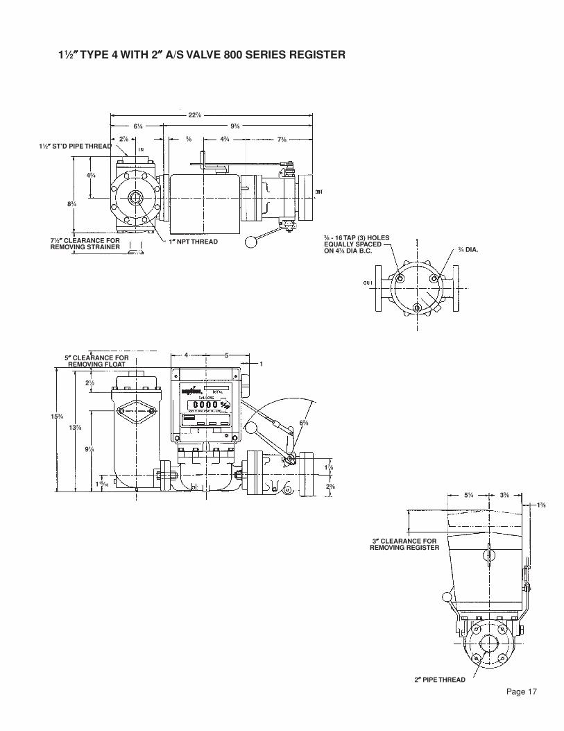
11⁄2″″″″″ TYPE 4 WITH 2″″″″″ A/S VALVE 800 SERIES REGISTER
11⁄2″″″″″ ST’D PIPE THREAD27⁄8
61⁄8
43⁄4
83⁄4
1″″″″″ NPT THREAD
227⁄8
5⁄8 43⁄4
93⁄8
4 5
21⁄2
137⁄8
91⁄4
115⁄16
153⁄4
17⁄8
23⁄8
65⁄8
51⁄4
2″″″″″ PIPE THREAD
33⁄8
3″″″″″ CLEARANCE FORREMOVING REGISTER
13⁄8
3⁄8 - 16 TAP (3) HOLESEQUALLY SPACEDON 47⁄8 DIA B.C. 3⁄4 DIA.
73⁄8
15″″″″″ CLEARANCE FORREMOVING FLOAT
71⁄2″″″″″ CLEARANCE FORREMOVING STRAINER
U.S.A./International1310 Emerald RoadGreenwood, SC 29646-9558Tel.: Toll-Free (800) 833-3357Tel.: Toll-Free (800) 833-3357T
(864) 223-1212Fax: (864) 223-0341
Specifications subject to change without prior notification.