Embed Size (px)
Citation preview
REV. 04/08/05 1
OPERATING INSTRUCTIONSTo Raise:
1. This crane is designed for engine lifting purposes only. When removing an engine from the vehicle, be sure that the front of the vehicle is not jammed against the hydraulic unit. Failure to observe this precaution could result in a broken hydraulic unit and a dropped engine.
2. Do not overload this crane beyond its rated capacity. Doing so may cause damage or failure of the engine crane.
3. Lower boom and load to the lowest possible point before moving load.
4. Do not allow load to swing or drop sharply while lowering and/or moving.
5. A visual inspection should be made before each use of the crane. Check for leaking hydraulic fluid and cracked, damaged, loose or missing parts.
6. Use only on flat level surfaces.
7. Keep hook clean and inspect periodically for damage.
8. When not using the crane, always leave the boom and pumper plunger all the way down.
INSPECTIONVisual inspection should be made before each use of the engine crane, checking for damaged, loose or missing parts. Any crane which appears to be damaged in any way, found to be badly worn or operates abnormally MUST BE REMOVED FROM SERVICE until necessary repairs are made. It is recommended that an annual inspection of the crane be made by a manufacturer’s authorized repair facility and that any defective parts, decal or warning labels be replaced with manufacturer’s specified parts.
OPERATING INSTRUCTIONS AND PARTS BREAKDOWNMODEL 520-6002 2 Ton Mobile Crane
DO NOT CRAWL UNDER ENGINE OR PLACE ANY PART OF YOUR BODY UNDER THE ENGINE AT ANY TIME DURING USE OF ENGINE CRANE, OR REMOVAL OF ENGINE.
THIS CRANE IS DESIGNED FOR ENGINE LIFTING PURPOSES ONLY.
WHEN REMOVING ENGINES FROM VEHICLES, BE SURE THAT THE FRONT OF THE VEHICLE IS NOT JAMMED AGAINST THE HYDRAULIC UNIT. FAILURE TO OBSERVE THIS WARNING COULD RESULT IN A DROPPED ENGINE.
A VISUAL INSPECTION SHOULD BE MADE BEFORE EACH USE OF THE CRANE, CHECKING FOR LEAKING HYDRAULIC FLUID AND CRACKED, DAMAGED, LOOSE OR MISSING PARTS.
DO NOT OVERLOAD. OVERLOADING CAN CAUSE DAMAGE TO OR FAILURE OF THE MOBILE CRANE.
LOWER BOOM AND LOAD TO THE LOWEST POSSIBLE POSITION BEFORE TRANSPORTING.
ASSURE THAT THE LOAD IS NOT ALLOWED TO DROP SUDDENLY OR SWING DURING TRANSPORTING.
MAKE SURE THAT BOOM IS FULLY LOWERED BEFORE ADDING OIL TO UNIT RESERVOIR.
THIS MOBILE CRANE IS DESIGNED FOR USE ONLY ON HARD LEVEL SURFACES CAPABLE OF SUSTAINING THE LOAD. USE ON OTHER THAN HARD LEVEL SURFACES CAN RESULT IN MOBILE CRANE INSTABILITY AND POSSIBLE LOSS OF LOAD.
NO ALTERATIONS TO THE MOBILE CRANE SHALL BE MADE. USE ONLY SLINGS OR CHAINS WITH CAPACITY GREATER THAN THAT OF THE LOAD BEING LIFTED.
READ, STUDY AND UNDERSTAND THE INSTRUCTION MANUAL PACKED WITH THIS CRANE BEFORE USING CRANE.
FAILURE TO HEED THESE WARNINGS MAY RESULT IN LOSS OF LOAD, DAMAGE TO CRANE, AND/OR FAILURE RESULTING IN PROPERTY DAMAGE, PERSONAL OR FATAL INJURY.
THIS OPERATING MANUAL CONTAINS IMPORTANT SAFETY INFORMATION. READ CAREFULLY AND UNDERSTAND ALL INFORMATION BEFORE OPERATING TOOL. SAVE THIS MANUAL FOR FUTURE USE.
520-6002_man040805.indd 1 4/8/05 1:26:00 PM

REV. 04/08/05 2
A
B
B
E
G
H
H
I
4
8
2
7
5
45
6
3
3
6
1
5
1
J
K
L
MC
D
D
ITEM PART NO. NO. DESCRIPTION QTY. *1 M14x30 Bolt 4 *2 M14x80 Bolt, Nut, Flat Washer 1 *3 M14x95 Bolt, Nut, Flat Washer 2 *4 M16x85 Bolt, Nut, Flat Washer 2 *5 M16x100 Bolt, Nut, Flat Washer 3 *6 M14x100 Bolt, Nut, Flat Washer 2 *7 M20x110 Bolt, Nut, Flat Washer 1 *8 M16x85 Bolt, Nut, Flat Washer 1
ITEM PART NO. NO. DESCRIPTION QTY. A Rear Support 1 B Front Legs 2 C Main Post Support 1 **D Rear Leg Ext. W/ Casters 2 RSSC350A 3-1/2" Caster **E Front Leg Ext. W/ Casters 2 RSSC301A 3" Caster G Main Post 1 H Support Brackets 2 I Boom 1 J Boom Ext. 1 **K RS5206002-K Hook w/ Chain 1 **L RS5080B 8 Ton Long Ram (incl. handle) 1 M RS5040BHDL Handle 1
* These parts are available only in bolt kit #RS5206002-15** These items may be purchased beyond the 180 day warranty.
PARTS BREAKDOWN — 520-6002 2 Ton Mobile Crane
1
520-6002_man040805.indd 2 4/8/05 1:26:01 PM
REV. 04/08/05 3
ASSEMBLY INSTRUCTIONS1. Locate the following parts and hardware: (1) ”A“
rear support leg, (2) ”B“ front legs, (2) ”D“ rear leg extensions with swivel casters, (4) #1 bolts, (2) #5 bolts, washers and nuts. Slip both ”D“ rear legs into ”A“ rear support, secure with (2) #1 bolts, finger-tighten only. Slip both ”B“ front legs onto the rear support. Secure with (2) #5 bolts, washers and nuts. DO NOT TIGHTEN.
2. Locate the following parts and hardware: (1) ”C“ main post support, (2) #6 bolt, washer and nut. Slide ”C“ main support over both front legs, lining-up holes of legs and support. Secure with (2) #3 bolt, washer and nut. DO NOT TIGHTEN.
3. Locate the following parts and hardware: (2) ”E“ front leg extensions with swivel casters, (2) #2 bolts. With swivel casters facing down slip both leg extensions into front legs and secure with (2) #1 bolts. Finger tighten only. NOTE: Never extend the front or rear legs beyond the line marked on the legs.
4. Locate the following parts and hardware: (1) ”G“ main post, (2) #3 nut, washer and bolt. Place ”G“ main post onto center of ”C“ main post support, lining-up holes with both parts, secure them with (2) #3 bolts, washers and nuts. Finger tighten only.
5. Locate the following parts and hardware: (2) ”H“ support brackets, (3) #5 bolts, washer and nuts. Assistance may be required for step 6 through 8. Place the one ”H“ support bracket on each side of the main post securing with (1) #5 bolt, washer and nut. Finger tighten only. NOTE: The support brackets should be on the inside of the frame. From the outside of the leg frame place one #4 bolt through the hole of the frame. At the same time, hold the lower end of the support bracket and line it up with the bolt that is being pushed through the holes. Secure it with the washer and nut. Repeat the same procedure for the other side. Tighten the bolts down. Now go back and tighten the bolts in step #5.
6. Locate the following parts and hardware: (1) ”L“ hydraulic ram, (2) #4 bolts, washers, and nuts. Place the hydraulic ram on the main post support bracket. Lean the ram against main post and secure it at the bottom with (1) #4 bolt, washer and nut.
7. Locate the following parts and hardware: (1) ”I“ boom, (1) #7 and (1) #4 bolt washer and nut, (1) ”M“ handle. Place the boom on top of the main post and secure with #7 bolt, washer and nut. Use the ”M“ handle to pump jack up approximately 2". Place front mounting bracket of the boom on top of the ram and secure with (1) #4 bolt washer and nut. Tighten all bolts in step 7 and 8.
8. Locate the following parts and hardware: (1) ”J“ boom extension, (1) #8 and #2 bolt, washer and nut, (1) ”K“ hook and chain. Slide boom extensions into boom making sure slot for chain faces down. Secure extension with (1) #8 bolt, washer and nut. Be sure to use the correct hole position for your particular job. NOTE: Four (4) positions available are 1/2 ton, 1 ton, 1-1/2 ton and 2 ton. Slide chain through the hole in the end of the boom extension and secure with #2 bolt, washer and nut.
9. Now go back and tighten down all the loose bolts and nuts. IMPORTANT NOTE: Sometimes during shipment and handling air gets into the hydraulic system causing poor lifting performance. Purge any air from system by fully opening release valve (turn valve counterclockwise). While holding end of ram cylinder down. Operate pump handle rapidly several times. NOTE: The capacity of the crane varies from 4000 lbs to 1000 lbs. These ratings are located on the side of the boom. Do not exceed the load rating of the boom. Whenever possible, use the boom in the retracted position where the capacity is the greatest. Extend the boom only when necessary to reach the load. Be sure the load is within the capacity limit for the particular boom position selected.
SPECIFICATIONSCapacity . . . . . . . . . . . . . . . . . . . . . . . . . . . . 4000 Lbs.Length: Operational . . . . . . . . . . . . . . . . . . . . 89-3/4"Width . . . . . . . . . . . . . . . . . . . . . . . . . . . . . . . . 50-3/4"Weight . . . . . . . . . . . . . . . . . . . . . . . . . . . . . . 268 Lbs.Boom Length By Position:1/2 ton . . . . . . . . . . . . . . . . . . . . . . . . . . . . . . . . . . . 78"1 ton . . . . . . . . . . . . . . . . . . . . . . . . . . . . . . . . . 68-1/2"1-1/2 ton . . . . . . . . . . . . . . . . . . . . . . . . . . . . . . . . . 59"2 ton . . . . . . . . . . . . . . . . . . . . . . . . . . . . . . . . . 49-5/8"
520-6002_man040805.indd 3 4/8/05 1:26:01 PM
REV. 04/08/05 4
Maximum weight capacity is 2 ton. Always check weight of engine and compare to the crane‘s rated capacity. Never exceed weight limit or loss of load may occur.
Visually inspect the floor surface before using crane. Floor must be level, smooth and hard. Floor should also be free of cracks and obstacles that could obstruct movement.
When removing engine from vehicle be sure that the front of vehicle is not up against the hydraulic unit. Lower boom to the lowest position before moving load. DO NOT allow load to swing or drop sharply as instability or loss of load may occur. Never perform any work or inspection on engine while it is on the crane. The engine must be transferred to a properly rated engine stand before work or inspection can be done to engine.
Before every use, visually inspect the crane for any loose points, signs of instability or leaking hydraulic fluid. This crane is designed for engine lifting purposes only. DO NOT attempt to use it for lifting any other heavy equipment as weight loss or imbalance may occur.
OWNER/USER RESPONSIBILITYThe owner and/or user must have a thorough understanding of the manufacturer’s operating instructions and warnings before using this engine crane. Personnel involved in the use and operation of equipment shall be careful, competent, trained and qualified in the safe use and operation of equipment and its proper use when servicing motor vehicles and their components. Warning information should be emphasized and understood. If the operator is not fluent in English, the manufacturer’s instructions and warnings shall be read to and discussed with the operator in the operator’s native language by the purchaser/owner, making sure that the operator comprehends its contents.
Owner and/or user must study and maintain for future reference the manfacturer’s instructions. Owner and/or user is responsible for keeping all warning labels and instruction manuals legible and intact. Replacement labels and literature are available from the manufacturer.
LIFTINGCAUTIONS
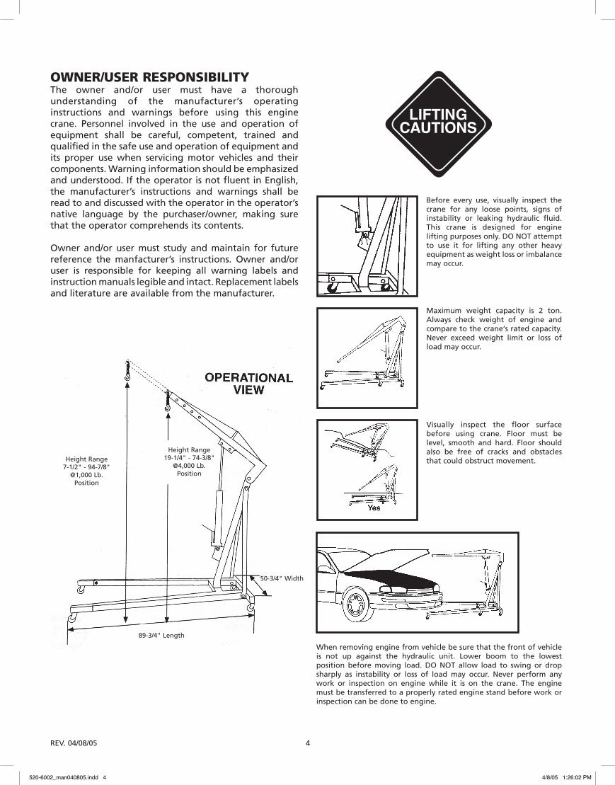
50-3/4" Width
89-3/4" Length
Height Range7-1/2" - 94-7/8"
@1,000 Lb.Position
Height Range19-1/4" - 74-3/8"
@4,000 Lb.Position
520-6002_man040805.indd 4 4/8/05 1:26:02 PM
REV. 04/08/05 5
NAPA LIFTING EQUIPMENT WARRANTY STATEMENT
Warranty Handling Procedures & Guidelinesfor Balkamp/NAPA Lifting Equipment
180 Day Warranty
Balkamp warrants that all jacks and service-related equipment will be free from defects in material and workmanship for a period of 180 days following the original date of purchase. This warranty is extended to the original retail purchaser only. If any jack or service-related item proves to be defective during this period, it will be replaced or repaired, at our option, without charge. This warranty does not apply to damage from accident, overload, misuse or abuse, nor does it apply to any equipment which has been altered or used with special attachments other than those recommended. This warranty does not cover repairs made by anyone who is not a Balkamp/NAPA Lifting Equipment Authorized Repair Center.
The following items possess an over-the-counter exchange warranty for 180 days. This allegedly defective product must be returned, accompanied by a receipt showing proof-of-purchase to Balkamp, via the NAPA AUTO PARTS store.
Bottle Jacks: 520-1037, 520-1038, 520-1039, 520-1040, 520-1041, 520-1042, 520-1021 and 520-1022
Floor Jacks: 520-1003, 520-1004, 520-1005 and 520-1006
Stands: 520-2000, 520-2001, 520-2002, 520-2005, 520-2006 and 520-2007
Hydraulic Power Units: 520-6004 and 520-6008
All other jacks or service-related equipment will be replaced or repaired at Balkamp’s option during the 180 day warranty period.
During the 180 day warranty period, all alleged defective product and/or parts must be shipped, freight prepaid, along with proof of date-of-purchase, to your nearest Balkamp/NAPA Lifting Equipment Authorized Warranty Center. Be certain to include your name, address and phone number along with proof-of-purchase information, and a brief description of the alleged defect. The product will be returned to the customer, freight prepaid.
Many alleged defectives may simply be handled by calling your nearest Service Center for parts. A list of authorized warranty service centers is provided with the product.
In no event shall Balkamp be liable for incidental or consequential damages. The liability of any claim for loss or damage arising out of the sale, resale or use of a jack or related service equipment, shall in no event exceed the purchase price. SOME STATES DO NOT ALLOW THE EXCLUSION OR LIMITATION OF INCIDENTAL OR CONSEQUENTIAL DAMAGES, SO THE ABOVE LIMITATION MAY NOT APPLY TO YOU.
THIS WARRANTY IS THE SOLE AND EXCLUSIVE WARRANTY PROVIDED IN CONNECTION WITH THE SALE OF BALKAMP/NAPA PROFESSIONAL LIFTING EQUIPMENT. ALL OTHER WARRANTIES, INCLUDING ANY IMPLIED WARRANTIES OF MERCHANTABILITY OR FITNESS FOR A PARTICULAR PURPOSE, ARE EXCLUDED.
THIS WARRANTY GIVES YOU SPECIFIC LEGAL RIGHTS AND YOU MAY ALSO HAVE OTHER RIGHTS WHICH VARY FROM STATE TO STATE.
520-6002_man040805.indd 5 4/8/05 1:26:02 PM
REV. 04/08/05 6
INSTRUCCIONES PARA ELFUNCIONAMIENTOPara levantarla:
1. Esta grúa está diseñada solamente para levantar motores. Cuando quite un motor del vehículo, asegúrese de que la parte delantera del vehículo no esté atrancada contra la unidad hidráulica. Al no seguir esta advertencia, puede provocar la ruptura de la unidad hidráulica y la caída del motor.
2. ¡No sobrecargue esta grúa más allá de su clasificación de capacidad! Al hacerlo, puede causar daños a la grúa o provocar que falle.
3. Baje el brazo de levantamiento y coloquelo en la posición más baja posible, antes de proceder a transportarlo.
4. NO permita que la carga pueda columpiar o pandearse brusquemente, al bajar y/o transportarla.
5. Debe proceder haciendo una verificación visual antes de cada utilización de la grúa, para asegurarse que no hayan escapes del fluido hidráulico y partes hendidas, dañadas, flojas o faltantes.
6. Utilicela solamente sobre superficies duras y planas.
7. Mantenga el gancho limpio y verifiquelo periódicamente para detectar daños.
8. Cuando no se utiliza la grúa, coloque siempre el brazo de levantamiento y el émbolo de la bomba completamente hacia abajo.
VERIFICACIÓNDebe hacer una verificación visual, antes de utilizar cada vez la grúa y así asegúrese que no haya condiciones anormales tales como daños o piezas faltantes o flojas. Cualquier grúa que parezca dañada o demasiado gastada, de alguna manera, o que funcione de manera anormal DEBE SER RETIRADA DEL SERVICIO. Recomendamos hacer una verificación anual de la grúa y sea realizada por un encargado de un centro de servicio reconocido por el fabricante, para reemplazar las piezas defectuosas, las calcomanías o etiquetas de advertencia con las piezas especificadas del fabricante.
INSTRUCCIONES PARA EL FUNCIONAMIENTO Y LISTA DE PIEZASMODELO # 520-6002 Grúa móvil - Capacidad 1.8 toneladas métricas
ESTE MANUAL PARA EL FUNCIONAMIENTO CONTIENE INFORMACIONES IMPORTANTES, PARA LA SEGURIDAD. LEA CUIDADOSAMENTE Y ASEGÚRESE DE COMPRENDER TODAS ESTAS INFORMACIONES, ANTES DE PROCEDER CON EL FUNCIONAMIENTO DE ESTE APARATO. CONSERVE ESTE MANUAL PARA TENER UNA REFERENCIA EVENTUAL.
ADVERTENCIA
ADVERTENCIA¡NO SE DESLICE UD. NI COLOQUE CUALQUIER PARTE DE SU CUERPO DEBAJO DEL MOTOR, EN NINGÚN MOMENTO, DURANTE EL USO DE
LA GRÚA PARA MOTOR O AL QUITAR EL MOTOR!
ESTA GRÚA ESTÁ DISEÑADA SOLAMENTE PARA LEVANTAR MOTORES.
CUANDO QUITE LOS MOTORES DE LOS VEHÍCULOS, ASEGÚRESE DE QUE LA PARTE DELANTERA DEL VEHÍCULO NO ESTÉ ATRANCADA CONTRA LA UNIDAD HIDRÁULICA. AL NO SEGUIR ESTA ADVERTENCIA, PUEDE PROVOCAR LA CAÍDA DEL MOTOR.
DEBE PROCEDER HACIENDO UNA VERIFICACIÓN VISUAL ANTES DE CADA UTILIZACIÓN DE LA GRÚA, PARA ASEGURARSE QUE NO HAYAN ESCAPES DEL FLUIDO HIDRÁULICO Y PARTES HENDIDAS, DAÑADAS, FLOJAS O FALTANTES.
¡NO LA SOBRECARGUE! UNA SOBRECARGA PUEDE CAUSAR DAÑOS A LA GRÚA O PROVOCAR QUE FALLE.
BAJE EL BRAZO DE LEVANTAMIENTO Y COLOQUELO EN LA POSICIÓN MÁS BAJA QUE SEA POSIBLE, ANTES DE PROCEDER A TRANSPORTARLO.
ASEGÚRESE DE QUE LA CARGA NO PUEDA PANDEAR BRUSCAMENTE O COLUMPIARSE DURANTE EL TRANSPORTE.
ASEGÚRESE DE QUE EL BRAZO DE LEVANTAMIENTO ESTÉ COMPLETAMENTE BAJADO, ANTE DE AÑADIR ACEITE DENTRO DEL TANQUE DE LA UNIDAD.
ESTA GRÚA ESTÁ DISEÑADA PARA SER UTILIZADA SOLAMENTE SOBRE SUPERFICIES DURAS Y PLANAS, QUE PUEDAN SOSTENER LA CARGA. AL UTILIZARLA EN OTROS LUGARES QUE NO SEAN SUPERFICIES DURAS, PUEDE PROVOCAR LA INESTABILIDAD DE LA GRÚA Y EL FALLO DE LA CARGA.
NUNCA HAGA MODIFICACIONES O ADAPTACIONES SOBRE LA GRÚA. UTILICE SOLAMENTE DISPOSITIVOS DE LEVANTAMIENTO O CADENAS QUE TENGAN UNA CAPACIDAD DE CARGA SUPERIOR A LA CARGA AL LEVANTAR.
LEA, ESTUDIE Y COMPRENDA LAS ADVERTENCIAS Y LAS INSTRUCCIONES DE FUNCIONAMIENTO INCLUIDAS EN EL EMBALAJE DE ESTA GRÚA, ANTES DE UTILIZARLA. SI NO SE SIGUEN ESTAS ADVERTENCIAS, SE PUEDE CAUSAR LA PÉRDIDA DE LA CARGA, PROVOCAR DAÑOS A LA GRÚA Y/O DAÑOS MATERIALES, LESIONES O LA MUERTE.
520-6002_man040805.indd 6 4/8/05 1:26:03 PM
REV. 04/08/05 7
INSTRUCCIONES DEL ENSAMBLADOEtapa 1. Encuentre las piezas siguientes y la ferretería: (1)
pata trasera para soporte “A”, (2) patas delanteras “B”, (2) extensiones de patas traseras con ruedecillas pivotantes “D”, (4) pernos #1, (2) pernos, arandelas y tuercas #5. Introduzca las dos patas traseras "D" dentro del soporte trasero “A” y fijelas con (2) pernos #1; aprietelas solamente a mano. Introduzca las dos patas delanteras “B” dentro del soporte trasero. Fijelas con (2) pernos, arandelas y tuercas #5. NO LOS APRIETE
Etapa 2. Encuentre las piezas siguientes y la ferretería: (1) soporte principal del poste “C”, (2) pernos, arandelas y tuercas #6. Introduzca el soporte principal del poste “C”, por encima de las dos patas delanteras, alineando los orificios de las patas y del soporte. Fijelo con (2) pernos, arandelas y tuercas #3. NO LOS APRIETE.
Etapa 3. Encuentre las piezas siguientes y la ferretería: (2) extensiones de patas delanteras equipadas con ruedecillas pivotantes “E”. Dirija las ruedecillas hacia el suelo e introduzca las dos extensiones de las patas dentro de las patas delanteras; fijelas con (2) pernos #1; aprietelos solamente a mano. NOTA: Nunca extienda la parte delantera de las patas traseras, más allá de la línea marcada sobre las patas.
Etapa 4. Encuentre las piezas siguientes y la ferretería: (1) poste principal “G”, (2) pernos, arandelas y tuercas #3. Coloque el poste principal “G” sobre el soporte principal del poste “C”, alineando los orificios de la dos piezas; fijelas con (2) pernos, arandelas y tuercas #3. Aprietelos solamente a mano.
Etapa 5. Encuentre las piezas siguientes y la ferretería: (2) soportes de fijación “H”, (3) perno, arandela y tuerca #5. Posiblamente necesitará ayuda para continuar con las etapas 6 hasta 8. Coloque un soporte de fijación en ambos lados del poste principal y fije los dos con (1) perno, arandela y tuerca #5. Aprietelos solamente a mano.
NOTA: Debe instalar los soportes de fijación en la parte interior de la estructura. A partir del lado exterior de la estructura de las patas, coloque un perno #4 dentro del orificio de la estructura, manteniendo a la vez la parte inferior del soporte y alineándolo con el perno introducido a través de los orificios. Fijelo con una arandela y una tuerca. Repita el mismo procedimiento en el otro lado. Apriete los pernos. En este momento, regrese y apriete los pernos de la etapa 5.
Etapa 6. Encuentre las piezas siguientes y la ferretería: (1) eje hidráulico para soporte “L”, (2) perno, arandela y tuerca #4. Coloque el eje hidráulico sobre el soporte de fijación del poste principal. Apoye el eje contra el poste principal y fijelo en la parte inferior, con (1) perno, arandela y tuerca #4.
Etapa 7. Encuentre las piezas siguientes y la ferretería: (1) brazo de levantamiento “I”, perno, arandela y tuerca #7 y (1) #4, y (1) mango “M”. Coloque el brazo de lavantamiento por encima del poste principal y fijelo con (1) perno, arandela y tuerca #4. Utilice el mango “M” para bombear el gato hidráulico de 5 cm (2") aproximadamente. Coloque el soporte delantero para el montaje del brazo de levantamiento por encima del eje hidráulico y fijelo en su lugar, con (1) perno, arandela y tuerca #4. Apriete los pernos de las etapas 7 y 8.
Etapa 8. Encuentre las piezas siguientes y la ferretería: (1) extensión para el brazo de levantamiento “J”, perno, arandela y tuerca #8 y (1) #2 y (1) gancho y cadena “K”. Introduzca las extensiones para el brazo de levantamiento dentro del brazo, asegurándose de que la ranura para la cadena esté dirigida hacia abajo. Fije la extensión con (1) perno, arandela y tuerca #8. Asegúrese de utilizar el orificio adecuado para la posición, de acuerdo con el trabajo al hacerlo.
NOTA: Las cuatro (4) posiciones disponibles son: 454 kg (1000 lb), 907 kg (2000 lb), 1.3 t.m. (3000 lb) y 2.8 t. m. (4000 lb). Introduzca la cadena a través del orificio que se encuentra en la extremidad de la extensión para el brazo de levantamiento y fijela en su lugar, con (1) perno, arandela y tuerca #2.
Etapa 9. En este momento, regrese y apriete todos los pernos y tuercas. NOTA IMPORTANTE: Es posible que durante el transporte y la manipulación, una cantidad de aire se introduzca dentro del sistema hidráulico. Para limpiarlo del sistema, abra completamente la válvula de aflojamiento, girando la válvula en el sentido contrario del reloj. Manteniendo la extremidad del cilindro del eje para soporte hacia abajo, haga funcionar rápidamente el mango de la bomba con muchos movimientos. NOTA: La capacidad de la grúa varía de 1.8 toneladas métricas a 454 kg (4,000 hasta 1,000 lb). Estas clasificaciones están colocadas en el lado del brazo de levantamiento. No exceda la clasificación de capacidad de carga del brazo de levantamiento. Cuando sea posible, utilice el brazo de levantamiento en posición retraída, donde se coloca la capacidad más grande. Extienda el brazo de levantamiento solamente cuando sea necesario, para reunirse con una carga. Asegúrese de que la carga esté en este lado del límite de capacidad, de acuerdo con la posición elegida para el brazo de levantamiento.
520-6002_man040805.indd 7 4/8/05 1:26:03 PM
REV. 04/08/05 8
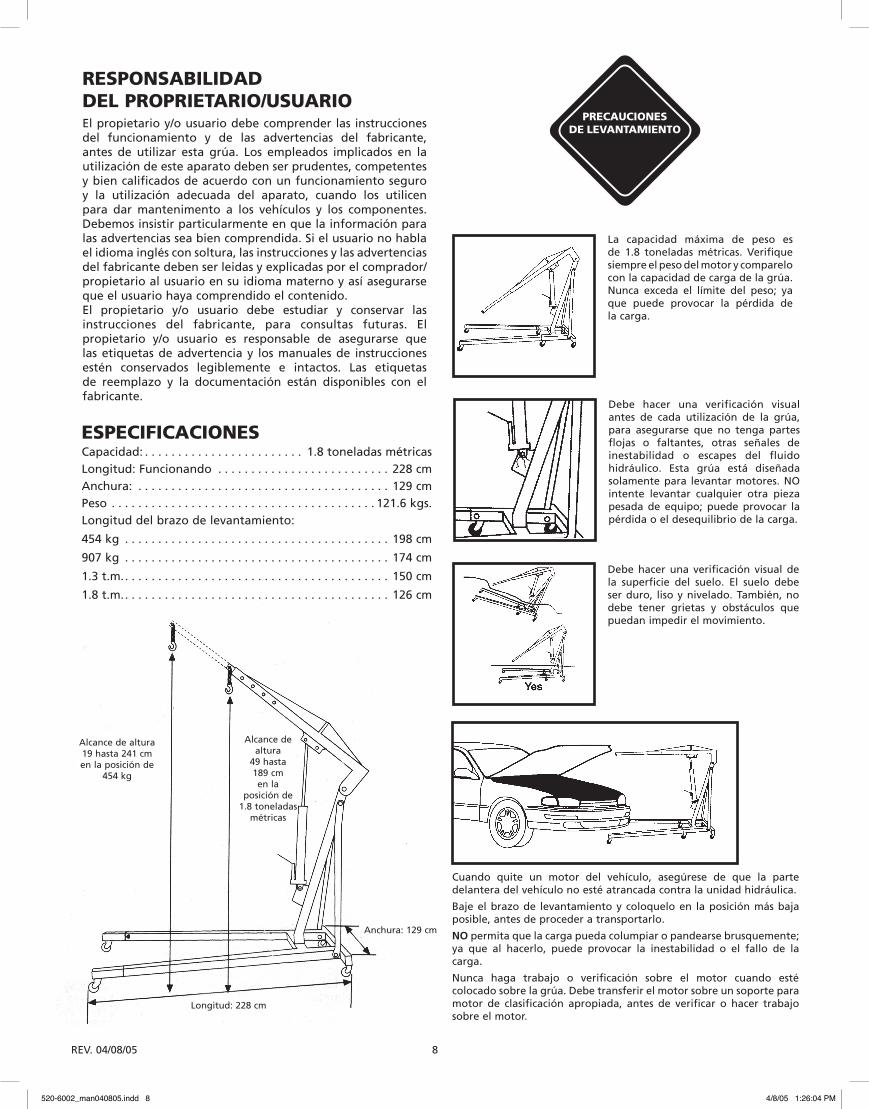
La capacidad máxima de peso es de 1.8 toneladas métricas. Verifique siempre el peso del motor y comparelo con la capacidad de carga de la grúa. Nunca exceda el límite del peso; ya que puede provocar la pérdida de la carga.
Debe hacer una verificación visual de la superficie del suelo. El suelo debe ser duro, liso y nivelado. También, no debe tener grietas y obstáculos que puedan impedir el movimiento.
Cuando quite un motor del vehículo, asegúrese de que la parte delantera del vehículo no esté atrancada contra la unidad hidráulica.
Baje el brazo de levantamiento y coloquelo en la posición más baja posible, antes de proceder a transportarlo.
NO permita que la carga pueda columpiar o pandearse brusquemente; ya que al hacerlo, puede provocar la inestabilidad o el fallo de la carga.
Nunca haga trabajo o verificación sobre el motor cuando esté colocado sobre la grúa. Debe transferir el motor sobre un soporte para motor de clasificación apropiada, antes de verificar o hacer trabajo sobre el motor.
Debe hacer una verificación visual antes de cada utilización de la grúa, para asegurarse que no tenga partes flojas o faltantes, otras señales de inestabilidad o escapes del fluido hidráulico. Esta grúa está diseñada solamente para levantar motores. NO intente levantar cualquier otra pieza pesada de equipo; puede provocar la pérdida o el desequilibrio de la carga.
RESPONSABILIDAD DEL PROPRIETARIO/USUARIOEl propietario y/o usuario debe comprender las instrucciones del funcionamiento y de las advertencias del fabricante, antes de utilizar esta grúa. Los empleados implicados en la utilización de este aparato deben ser prudentes, competentes y bien calificados de acuerdo con un funcionamiento seguro y la utilización adecuada del aparato, cuando los utilicen para dar mantenimento a los vehículos y los componentes. Debemos insistir particularmente en que la información para las advertencias sea bien comprendida. Si el usuario no habla el idioma inglés con soltura, las instrucciones y las advertencias del fabricante deben ser leidas y explicadas por el comprador/propietario al usuario en su idioma materno y así asegurarse que el usuario haya comprendido el contenido. El propietario y/o usuario debe estudiar y conservar las instrucciones del fabricante, para consultas futuras. El propietario y/o usuario es responsable de asegurarse que las etiquetas de advertencia y los manuales de instrucciones estén conservados legiblemente e intactos. Las etiquetas de reemplazo y la documentación están disponibles con el fabricante.
PRECAUCIONES DE LEVANTAMIENTO
ESPECIFICACIONESCapacidad: . . . . . . . . . . . . . . . . . . . . . . . . 1.8 toneladas métricasLongitud: Funcionando . . . . . . . . . . . . . . . . . . . . . . . . . . 228 cmAnchura: . . . . . . . . . . . . . . . . . . . . . . . . . . . . . . . . . . . . . . 129 cmPeso . . . . . . . . . . . . . . . . . . . . . . . . . . . . . . . . . . . . . . . . 121.6 kgs.Longitud del brazo de levantamiento:
454 kg . . . . . . . . . . . . . . . . . . . . . . . . . . . . . . . . . . . . . . . . 198 cm
907 kg . . . . . . . . . . . . . . . . . . . . . . . . . . . . . . . . . . . . . . . . 174 cm
1.3 t.m.. . . . . . . . . . . . . . . . . . . . . . . . . . . . . . . . . . . . . . . . 150 cm
1.8 t.m.. . . . . . . . . . . . . . . . . . . . . . . . . . . . . . . . . . . . . . . . 126 cm
Longitud: 228 cm
Anchura: 129 cm
Alcance de altura19 hasta 241 cmen la posición de
454 kg
Alcance de altura
49 hasta 189 cmen la
posición de 1.8 toneladas
métricas
520-6002_man040805.indd 8 4/8/05 1:26:04 PM
REV. 04/08/05 9
GARANTÍA - INFORMACIÓN NAPA Instrucciones y procedimientos para la garantía para:
Equipo de levantamiento Balkamp / NAPA GARANTÍA DE 180 DÍAS PARA: SERIE 520
Balkamp garantiza que todos los gatos hidráulicos y otros equipos parecidos de servicio, estarán exentos de cualquier falta de material o de mano de obra durante un periodo de 180 días, a partir de la fecha de la compra original. Esta garantía se aplica solamente al comprador original (detallista). Si cualquier gato u otro equipo parecido falta durante este periodo, lo reemplazaremos o lo repararemos, a nuestra elección y sin costo. Esta garantía no se aplica a los daños provocados por a un accidente, una sobrecarga, una utilización mala o excesiva; esta garantía tampoco se aplica a cualquier pieza de equipo que ha sido modificada o utilizada con accesorios especiales, excepto los accesorios recomendados. Esta garantía no cubre las reparaciones ejecutadas por cualquier centro de reparaciones que no sea une centro autorizado de reparaciones Balkamp/NAPA, para el equipo de levantamiento.
Los artículos siguientes tienen una garantía de cambio directo en la tienda por 180 días. El producto presumiblemente defectuoso, debe devolverse a Balkamp, provisto de un recibo, demostrando la prueba de la compra, por medio de una tienda de piezas automóviles NAPA.
Gatos-botella: 520-1037, 520-1038, 520-1039, 520-1040, 520-1041, 520-1042, 520-1021 y 520-1022
Gatos para suelo: 520-1003, 520-1004, 520-1005 y 520-1006
Gatos para soporte: 520-2000, 520-2001, 520-2002, 520-2005, 520-2006 y 520-2007
Unidades de fuerza hydráulica: 520-6004 y 520-6008
Todos los otros gatos hidráulicos y otros equipos parecidos de servicio serán reemplazados o reparados, a la elección de Balkamp, durante el periodo de garantía de 180 días.
Durante el periodo de garantía de 180 días, cualquier producto y/o pieza presumiblemente defectuoso debe devolverse, franco de porte, provisto con una prueba de la fecha de compra, al centro autorizado más cercano, para la garantía Balkamp/NAPA, por el equipo profesional de levantamiento. Asegúrese de incluir su nombre, dirección y número de teléfono, incluyendo la información de la prueba de la compra y una descripción breve de la presumible defectuosidad. El producto será devuelto al consumidor, franco de porte.
Muchas presumibles defectuosidades pueden ser resueltas, llamando a su centro local de servicio para piezas.
En cualquier caso, Balkamp no será responsable de los daños fortuitos o indirectos. La responsabilidad de cualquier reclamación por pérdidas o daños debidos a esta venta, reventa o utilización de este gato o de cualesquiera otros equipos parecidos, no excederá el precio de compra. ALGUNOS ESTADOS O PROVINCIAS NO PERMITEN LA EXCLUSIÓN O LA LIMITACIÓN DE LOS DAÑOS FORTUITOS O INDIRECTOS, POR LO QUE ES POSIBLE QUE ESTA LIMITACIÓN NO SEA APLICADA A UD.
ESTA GARANTÍA ES LA GARANTÍA ÚNICA Y EXCLUSIVA, RELACIONADA CON LA COMPRA DEL EQUIPO PROFESIONAL PARA LEVANTAMIENTO BALKAMP/NAPA. TODAS LAS OTRAS GARANTÍAS, INCLUYENDO TODAS LAS OTRAS GARANTÍAS IMPLÍCITAS DE COMERCIALIZACIÓN O DE FIABILIDAD PARA UN PROPÓSITO PARTICULAR, ESTÁN EXCLUIDAS.
ESTA GARANTÍA LE DA DERECHOS LEGALES ESPECÍFICOS, Y, UD. TAMBIÉN PUEDE TENER OTROS DERECHOS QUE VARÍAN DE ESTADO EN ESTADO O DE PROVINCIA EN PROVINCIA.
520-6002_man040805.indd 9 4/8/05 1:26:04 PM

REV. 04/08/05 10
DIRECTIVES DE FONCTIONNEMENTPour soulever: 1. Cette grue est conçue seulement comme un mécanisme
de levage de moteur. Lors du retrait d'un moteur hors d'un véhicule, s'assurer que la partie avant du véhicule n'est pas coincée contre l'unité hydraulique. Ne pas tenir compte de cette mise en garde pourrait provoquer le bris de l'unité hydraulique et la chute du moteur.
2. Ne pas surcharger cette grue au-delà de la capacité prévue. La surcharge peut endommager ou produire un affaissement de la grue mobile.
3. Abaisser le bras de levage et charger à la position la plus basse possible, avant de procéder au transport.
4. Ne pas permettre que la charge puisse se balancer ou s'affaisser brusquement; lors d'un abaissement ou d'un transport.
5. Une vérification visuelle devrait être faite avant chaque utilisation de la grue mobile. Il faut s’assurer qu’il n’y ait pas de fuites du fluide hydraulique et qu’il n’y ait pas de conditions anormales comme des dommages, pièces manquantes ou desserrées.
6. N'utiliser que sur des surfaces unies et de niveau.
7. Maintenir le crochet propre et vérifier périodiquement pour détecter la présence de dommages.
8. Lorsque la grue n'est pas en service, il faut toujours maintenir le bras de levage et le piston de la pompe abaissés complètement.
VÉRIFICATIONUne vérification visuelle devrait être faite avant chaque utilisation de la grue mobile, pour s’assurer qu’il n’y ait pas de fuites du fluide hydraulique et qu’il n’y ait pas de conditions anormales comme des dommages, pièces manquantes ou desserrées. Toute grue mobile qui paraît endommagée de quelque façon, qui semble trop usée ou qui fonctionne de manière anormale DOIT ÊTRE RETIRÉE DU SERVICE, jusqu'à ce que les réparations nécessaires soient effectuées. Il est recommandé qu’une vérification annuelle de la grue mobile soit effectuée par un employé d’un centre de service reconnu par le manufacturier, afin de remplacer toutes pièces défectueuses, autocollants ou étiquettes de mise en garde par des pièces de remplacement spécifiées par le manufacturier. Une liste des centres de service reconnus est disponible auprès du manufacturier.
NE VOUS GLISSEZ PAS SOUS LE MOTEUR OU NE PLACEZ AUCUNE PARTIE DE VOTRE CORPS À AUCUN MOMENT PENDANT L’UTILISATION
DE LA GRUE POUR MOTEUR OU LE RETRAIT DU MOTEUR.
CETTE GRUE EST CONÇUE SEULEMENT COMME UN MÉCANISME DE LEVAGE DE MOTEUR. LORS DU RETRAIT DE MOTEURS HORS DES VÉHICULES, S'ASSURER QUE LA PARTIE AVANT DU VÉHICULE N’EST PAS COINCÉE CONTRE L’UNITÉ HYDRAULIQUE. NE PAS TENIR COMPTE DE CETTE MISE EN GARDE POURRAIT PROVOQUER LA CHUTE DU MOTEUR.UNE VÉRIFICATION VISUELLE DEVRAIT ÊTRE FAITE AVANT CHAQUE UTILISATION DE LA GRUE, POUR S’ASSURER QU’IL N’Y AIT PAS DE FUITES DU FLUIDE HYDRAULIQUE ET QU’IL N’Y AIT PAS DE CONDITIONS ANORMALES COMME DES DOMMAGES, PIÈCES MANQUANTES OU DESSERRÉES. NE PAS SURCHARGER, LA SURCHARGE PEUT ENDOMMAGER OU PRODUIRE UN AFFAISSEMENT DE LA GRUE MOBILE.ABAISSER LE BRAS DE LEVAGE ET CHARGER À LA POSITION LA PLUS BASSE POSSIBLE, AVANT DE PROCÉDER AU TRANSPORT.S’ASSURER QUE LA CHARGE NE PEUT S’AFFAISSER BRUSQUEMENT OU SE BALANCER DURANT LE TRANSPORT.S’ASSURER QUE LE BRAS DE LEVAGE EST COMPLÈTEMENT ABAISSÉ, AVANT D’AJOUTER DE L’HUILE DANS LE RÉSERVOIR DE L’UNITÉ.CETTE GRUE EST CONÇUE POUR ÊTRE UTILISÉE SUR DES SURFACES DURES ET PLANES, CAPABLES DE SUPPORTER LA CHARGE. SON UTILISATION AILLEURS QUE SUR DES SURFACES DURES ET PLANES, PEUT RÉSULTER EN UNE INSTABILITÉ DE LA GRUE ET LA POSSIBILITÉ DE LA PERTE DE LA CHARGE.VOUS NE DEVEZ FAIRE AUCUNE MODIFICATION À LA GRUE. N’UTILISER QUE DES DISPOSITIFS DE LEVAGE OU DES CHAÎNES OFFRANT UNE CAPACITÉ DE CHARGE DÉPASSANT LA CHARGE À SOULEVER.LISEZ, ÉTUDIEZ ET COMPRENEZ LE MANUEL DE FONCTIONNEMENT, INCLUS DANS L’EMBALLAGE DE CETTE GRUE, AVANT DE FAIRE FONCTIONNER LA GRUE. NE PAS TENIR COMPTE DE CES MISES EN GARDE POURRAIT CAUSER DES DOMMAGES À LA GRUE, PROVOQUER UNE PERTE DE LA CHARGE, DES DOMMAGES À LA PROPRIÉTÉ, DES BLESSURES OU LA MORT.
DIRECTIVES DE FONCTIONNEMENT ET LISTE DE PIÈCESMODÈLE # 520-6002 Grue mobile - Capacité 1,8 tonnes métriques
CE MANUEL DE FONCTIONNEMENT RENFERME DES RENSEIGNEMENTS IMPORTANTS, RELATIFS À LA SÉCURITÉ. LISEZ ATTENTIVEMENT ET ASSUREZ-VOUS DE COMPRENDRE TOUS CES RENSEIGNEMENTS, AVANT DE PROCÉDER AU FONCTIONNEMENT DE CET OUTIL. CONSERVEZ CE MANUEL POUR RÉFÉRENCE ÉVENTUELLE.
520-6002_man040805.indd 10 4/8/05 1:26:05 PM
REV. 04/08/05 11
DIRECTIVES D'ASSEMBLAGEÉtape 1. Trouvez les pièces suivantes et la quincaillerie:
(1) patte arrière de support “A”, (2) pattes avant “B”, (2) extensions de pattes arrière avec roulettes pivotantes “D”, (4) boulons #1, (2) boulons, rondelles et écrous #5. Introduisez les deux pattes arrière “D” dans le support arrière “A” et fixez à l’aide de (2) boulons #1; resserrez-les à la main seulement. Introduisez les deux pattes avant “B” dans le support arrière. Fixez à l’aide de (2) boulons, rondelles et écrous #5. NE PAS RESSERRER.
Étape 2. Trouvez les pièces suivantes et la quincaillerie: (1) support principal de poteau “C”, (2) boulons, rondelles et écrous #6. Introduisez le support principal de poteau “C”, par-dessus les deux pattes avant, en alignant les orifices des pattes et du support. Fixez à l’aide de (2) boulons, rondelles et écrous #3. NE PAS RESSERRER.
Étape 3. Trouvez les pièces suivantes et la quincaillerie: (2) extensions de pattes avant munies de roulettes pivotantes “E”. Dirigez les roulettes vers le sol et introduisez les deux extensions de pattes dans les pattes avant; fixez à l’aide de (2) boulons #1; resserrez-les à la main seulement. REMARQUE: N’allongez jamais la partie avant des pattes arrière, au-delà de la ligne marquée sur les pattes.
Étape 4. Trouvez les pièces suivantes et la quincaillerie: (1) poteau principal “G”, (2) boulons, rondelles et écrous #3. Placez le poteau principal “G” sur le support principal de poteau “C”, en alignant les orifices des deux pièces; fixez-les à l’aide de (2) boulons, rondelles et écrous #3. Resserrez-les à la main seulement.
Étape 5. Trouvez les pièces suivantes et la quincaillerie: (2) supports de fixation “H”, (3) boulon, rondelle et écrou #5. Il est possible que vous ayez besoin d’aide pour les étapes 6 à 8. Placez un support de fixation de chaque côté du poteau principal et fixez-les en place à l’aide de (1) boulon, rondelle et écrou #5 chacun. Resserrez-les à la main seulement. REMARQUE: Les supports de fixation devraient être installés à la partie interne de la structure. À partir du côté extérieur de la structure des pattes, placez un boulon #4 dans l’orifice de la structure, tout en maintenant à la fois la partie inférieure du support de fixation et en l’alignant au boulon introduit à travers les orifices. Fixez-le à l’aide d’une rondelle et d’un écrou. Répétez la même procédure de l’autre côté. Resserrez les boulons. À ce moment-ci, retournez et resserrez les boulons de l’étape 5.
Étape 6. Trouvez les pièces suivantes et la quincaillerie: (1) arbre hydraulique de support “L”, (1) boulon, rondelle et écrou #7 et (1) #4. Placez l’arbre hydraulique sur le support de fixation du poteau principal. Penchez l’arbre contre le poteau principal et fixez-le à la partie inférieure, à l’aide de (1) boulon, rondelle et écrou #4.
Étape 7. Trouvez les pièces suivantes et la quincaillerie: (1) bras de levage “I”, boulon, rondelle et écrou #7, (1) #4 et (1) manche “M”. Placez le bras de levage par-dessus le poteau principal et fixez-le à l’aide de (1) boulon, rondelle et écrou #4. Utilisez le manche “M” pour pomper le cric d’environ 5 cm. Placez le support de montage avant du bras de levage par-dessus l’arbre hydraulique et fixez-le en place, à l’aide de (1) boulon, rondelle et écrou #4. Resserrez les boulons des étapes 7 et 8.
Étape 8. Trouvez les pièces suivantes et la quincaillerie: (1) extension de bras de levage “J”, (1) boulon, rondelle et écrou #8 et (1) #2, (1) crochet et chaîne “K”. Introduisez les extensions de bras de levage dans le bras, en vous assurant que la rainure pour la chaîne est dirigée vers le bas. Fixez l’extension, à l’aide (1) boulon, rondelle et écrou #8. Assurez-vous d’utiliser l’orifice adéquat de position, selon le travail à exécuter. REMARQUE: Les quatre (4) positions disponibles sont: 454 kg, 907 kg, 1,3 t.m. et 1,8 t.m.. Introduisez la chaîne à travers l’orifice, situé à l’extrémité de l’extension de bras de levage et fixez-la en place, à l’aide de (1) boulon, rondelle et écrou #2.
Étape 9. À ce moment-ci, retournez et resserrez tous les boulons et écrous. REMARQUE IMPORTANTE: Parfois durant le transport et la manutention, il est possible que de l’air ait été emprisonné dans le système hydraulique, qui produira de mauvais résultats. Pour purger l’air du système, ouvrez complètement la valve de relâchement (en tournant la valve dans le sens contraire des aiguilles d’une montre). Tout en maintenant l’extrémité du cylindre de l’arbre hydraulique vers le bas, faites fonctionner rapidement le manche de la pompe à plusieurs reprises. REMARQUE: La capacité de la grue varie de 1,8 tonnes métriques à 454 kg (4,000 à 1,000 lb). Ces classifications sont situées sur le côté du bras de levage. Ne pas excéder la classification de capacité de charge du bras de levage. Lorsque possible, utilisez le bras de levage en position rétractée, où la capacité est la plus grande. N’étendez le bras de levage que lorsque nécessaire, pour rejoindre une charge. Assurez-vous que la charge est en deçà de la limite de capacité, suivant la position choisie du bras de levage.
520-6002_man040805.indd 11 4/8/05 1:26:05 PM
REV. 04/08/05 12
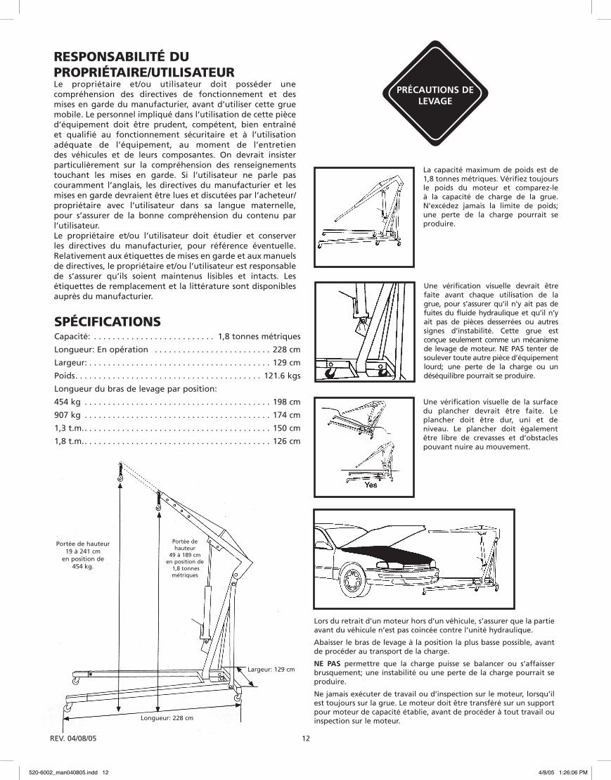
La capacité maximum de poids est de 1,8 tonnes métriques. Vérifiez toujours le poids du moteur et comparez-le à la capacité de charge de la grue. N’excédez jamais la limite de poids; une perte de la charge pourrait se produire.
Une vérification visuelle de la surface du plancher devrait être faite. Le plancher doit être dur, uni et de niveau. Le plancher doit également être libre de crevasses et d’obstacles pouvant nuire au mouvement.
Une vérification visuelle devrait être faite avant chaque utilisation de la grue, pour s’assurer qu’il n’y ait pas de fuites du fluide hydraulique et qu’il n’y ait pas de pièces desserrées ou autres signes d’instabilité. Cette grue est conçue seulement comme un mécanisme de levage de moteur. NE PAS tenter de soulever toute autre pièce d’équipement lourd; une perte de la charge ou un déséquilibre pourrait se produire.
RESPONSABILITÉ DU PROPRIÉTAIRE/UTILISATEURLe propriétaire et/ou utilisateur doit posséder une compréhension des directives de fonctionnement et des mises en garde du manufacturier, avant d’utiliser cette grue mobile. Le personnel impliqué dans l’utilisation de cette pièce d’équipement doit être prudent, compétent, bien entraîné et qualifié au fonctionnement sécuritaire et à l’utilisation adéquate de l’équipement, au moment de l’entretien des véhicules et de leurs composantes. On devrait insister particulièrement sur la compréhension des renseignements touchant les mises en garde. Si l’utilisateur ne parle pas couramment l’anglais, les directives du manufacturier et les mises en garde devraient être lues et discutées par l’acheteur/ propriétaire avec l’utilisateur dans sa langue maternelle, pour s’assurer de la bonne compréhension du contenu par l’utilisateur.Le propriétaire et/ou l’utilisateur doit étudier et conserver les directives du manufacturier, pour référence éventuelle. Relativement aux étiquettes de mises en garde et aux manuels de directives, le propriétaire et/ou l’utilisateur est responsable de s’assurer qu’ils soient maintenus lisibles et intacts. Les étiquettes de remplacement et la littérature sont disponibles auprès du manufacturier.
PRÉCAUTIONS DE LEVAGE
SPÉCIFICATIONSCapacité: . . . . . . . . . . . . . . . . . . . . . . . . . . 1,8 tonnes métriques
Longueur: En opération . . . . . . . . . . . . . . . . . . . . . . . . . 228 cm
Largeur: . . . . . . . . . . . . . . . . . . . . . . . . . . . . . . . . . . . . . . . 129 cm
Poids. . . . . . . . . . . . . . . . . . . . . . . . . . . . . . . . . . . . . . . . 121.6 kgs
Longueur du bras de levage par position:
454 kg . . . . . . . . . . . . . . . . . . . . . . . . . . . . . . . . . . . . . . . . 198 cm
907 kg . . . . . . . . . . . . . . . . . . . . . . . . . . . . . . . . . . . . . . . . 174 cm
1,3 t.m.. . . . . . . . . . . . . . . . . . . . . . . . . . . . . . . . . . . . . . . . 150 cm
1,8 t.m.. . . . . . . . . . . . . . . . . . . . . . . . . . . . . . . . . . . . . . . . 126 cm
Lors du retrait d’un moteur hors d’un véhicule, s’assurer que la partie avant du véhicule n’est pas coincée contre l’unité hydraulique.
Abaisser le bras de levage à la position la plus basse possible, avant de procéder au transport de la charge.
NE PAS permettre que la charge puisse se balancer ou s’affaisser brusquement; une instabilité ou une perte de la charge pourrait se produire.
Ne jamais exécuter de travail ou d’inspection sur le moteur, lorsqu’il est toujours sur la grue. Le moteur doit être transféré sur un support pour moteur de capacité établie, avant de procéder à tout travail ou inspection sur le moteur.Longueur: 228 cm
Largeur: 129 cm
Portée de hauteur19 à 241 cm
en position de 454 kg.
Portée de hauteur
49 à 189 cmen position de
1,8 tonnes métriques
520-6002_man040805.indd 12 4/8/05 1:26:06 PM
REV. 04/08/05 13
GARANTIE - INFORMATION NAPA Directives et procédures pour la garantie pour:
Équipement de levage Balkamp/NAPA GARANTIE DE 180 JOURS POUR: SÉRIE 520
Balkamp garantit que tous ses crics et autre équipement apparenté de service, sera libre de tout défaut de matériel et de main-d’œuvre durant une période de 180 jours, suivant la date de l’achat original. Cette garantie ne s’applique qu’à l’acheteur original d’un article acheté au détail. Si tout cric ou autre équipement apparenté devient défectueux durant cette période, il sera remplacé ou réparé, à notre choix, sans aucun frais. Cette garantie ne s’applique pas aux dommages dus à un accident, une surcharge, un mauvais usage ou un abus; cette garantie ne s’applique pas non plus à toute pièce d’équipement ayant été modifiée ou utilisée avec des accessoires spéciaux, autres que les accessoires recommandés. Cette garantie ne couvre pas les réparations exécutées par quelque centre de réparations, qui n’est pas un centre de réparations autorisé Balkamp/NAPA pour équipement de levage.
Les articles suivants possèdent une garantie d’échange direct en magasin, de 180 jours. Le produit présumé défectueux doit être retourné à Balkamp, muni d’un reçu démontrant la preuve d’achat, par le biais d’un magasin de pièces d’automobiles NAPA.
Crics-bouteille: 520-1037, 520-1038, 520-1039, 520-1040, 520-1041, 520-1042, 520-1021 et 520-1022
Crics de plancher: 520-1003, 520-1004, 520-1005 et 520-1006
Chandelles: 520-2000, 520-2001, 520-2002, 520-2005, 520-2006 et 520-2007 Unités de force hydraulique: 520-6004 et 520-6008
Tous les autres crics et autre équipement apparenté de service seront remplacés ou réparés, au choix de Balkamp, durant la période de garantie de 180 jours.
Durant la période de garantie de 180 jours, tout produit et/ou pièce présumé défectueux doit être retourné, franc de port, muni d’une preuve de la date d’achat, au centre autorisé le plus proche pour la garantie Balkamp/NAPA, pour équipement professionnel de levage. Assurez-vous d’inclure votre nom, adresse et numéro de téléphone, incluant les renseignements de preuve d’achat, ainsi qu’une brève description de la présumée défectuosité. Le produit sera retourné franc de port au consommateur.
Plusieurs présumées défectuosités peuvent être réglées, en contactant votre centre de service pour pièces de votre localité.
En aucun cas, Balkamp ne sera responsable de dommages fortuits ou indirects. La responsabilité de toute réclamation pour pertes ou dommages dus à cette vente, revente ou utilisation de ce cric ou de tout autre équipement apparenté, n’excédera en aucun cas le prix de l’achat. CERTAINS ÉTATS OU PROVINCES NE PERMETTENT PAS L’EXCLUSION OU LA LIMITATION DES DOMMAGES FORTUITS OU INDIRECTS; IL EST DONC POSSIBLE QUE LA LIMITATION CI-HAUT MENTIONNÉE, NE S’APPLIQUE PAS À VOUS.
LA PRÉSENTE GARANTIE EST LA GARANTIE UNIQUE ET EXCLUSIVE, RELATIVE À L’ACHAT D’ÉQUIPEMENT DE LEVAGE BALKAMP/NAPA. TOUTES AUTRES GARANTIES, INCLUANT TOUTES AUTRES GARANTIES IMPLICITES DE VALIDITÉ MARCHANDE OU DE FIABILITÉ RELATIVES À UN BUT PARTICULIER, SONT EXCLUSES.
CETTE GARANTIE VOUS CONFÈRE DES DROITS JURIDIQUES PARTICULIERS, AUXQUELS PEUVENT S’AJOUTER D’AUTRES DROITS, VARIANT SELON L’ÉTAT OU LA PROVINCE.
520-6002_man040805.indd 13 4/8/05 1:26:06 PM