Embed Size (px)
Citation preview

Operating Instructions and Parts Manual 12-inch Jointer-Planer Models JJP-12, JJP-12HH
JET 427 New Sanford Road LaVergne, Tennessee 37086 Part No. M-708475 Ph.: 800-274-6848 Revision D 10/2014 www.jettools.com Copyright © 2014 JET
2
1.0 Warranty and service JET warrants every product it sells against manufacturers’ defects. If one of our tools needs service or repair, please contact Technical Service by calling 1-800-274-6846, 8AM to 5PM CST, Monday through Friday.
Warranty Period The general warranty lasts for the time period specified in the literature included with your product or on the official JET branded website.
• JET products carry a limited warranty which varies in duration based upon the product. (See chart below) • Accessories carry a limited warranty of one year from the date of receipt. • Consumable items are defined as expendable parts or accessories expected to become inoperable within a
reasonable amount of use and are covered by a 90 day limited warranty against manufacturer’s defects.
Who is Covered This warranty covers only the initial purchaser of the product from the date of delivery.
What is Covered This warranty covers any defects in workmanship or materials subject to the limitations stated below. This warranty does not cover failures due directly or indirectly to misuse, abuse, negligence or accidents, normal wear-and-tear, improper repair, alterations or lack of maintenance. JET woodworking machinery is designed to be used with Wood. Use of these machines in the processing of metal, plastics, or other materials may void the warranty. The exceptions are acrylics and other natural items that are made specifically for wood turning.
Warranty Limitations Woodworking products with a Five Year Warranty that are used for commercial or industrial purposes default to a Two Year Warranty. Please contact Technical Service at 1-800-274-6846 for further clarification.
How to Get Technical Support Please contact Technical Service by calling 1-800-274-6846. Please note that you will be asked to provide proof of initial purchase when calling. If a product requires further inspection, the Technical Service representative will explain and assist with any additional action needed. JET has Authorized Service Centers located throughout the United States. For the name of an Authorized Service Center in your area call 1-800-274-6846 or use the Service Center Locator on the JET website.
More Information JET is constantly adding new products. For complete, up-to-date product information, check with your local distributor or visit the JET website.
How State Law Applies This warranty gives you specific legal rights, subject to applicable state law.
Limitations on This Warranty JET LIMITS ALL IMPLIED WARRANTIES TO THE PERIOD OF THE LIMITED WARRANTY FOR EACH PRODUCT. EXCEPT AS STATED HEREIN, ANY IMPLIED WARRANTIES OF MERCHANTABILITY AND FITNESS FOR A PARTICULAR PURPOSE ARE EXCLUDED. SOME STATES DO NOT ALLOW LIMITATIONS ON HOW LONG AN IMPLIED WARRANTY LASTS, SO THE ABOVE LIMITATION MAY NOT APPLY TO YOU. JET SHALL IN NO EVENT BE LIABLE FOR DEATH, INJURIES TO PERSONS OR PROPERTY, OR FOR INCIDENTAL, CONTINGENT, SPECIAL, OR CONSEQUENTIAL DAMAGES ARISING FROM THE USE OF OUR PRODUCTS. SOME STATES DO NOT ALLOW THE EXCLUSION OR LIMITATION OF INCIDENTAL OR CONSEQUENTIAL DAMAGES, SO THE ABOVE LIMITATION OR EXCLUSION MAY NOT APPLY TO YOU. JET sells through distributors only. The specifications listed in JET printed materials and on official JET website are given as general information and are not binding. JET reserves the right to effect at any time, without prior notice, those alterations to parts, fittings, and accessory equipment which they may deem necessary for any reason whatsoever. JET® branded products are not sold in Canada by JPW Industries, Inc.
Product Listing with Warranty Period 90 Days – Parts; Consumable items; Light-Duty Air Tools 1 Year – Motors; Machine Accessories; Heavy-Duty Air Tools; Pro-Duty Air Tools 2 Year – Metalworking Machinery; Electric Hoists, Electric Hoist Accessories; Woodworking Machinery used for industrial or commercial purposes 5 Year – Woodworking Machinery Limited Lifetime – JET Parallel clamps; VOLT Series Electric Hoists; Manual Hoists; Manual Hoist Accessories; Shop Tools; Warehouse & Dock products; Hand Tools
NOTE: JET is a division of JPW Industries, Inc. References in this document to JET also apply to JPW Industries, Inc., or any of its successors in interest to the JET brand.

3
2.0 Table of contents Section Page 1.0 Warranty and service ..................................................................................................................................... 2 2.0 Table of contents ............................................................................................................................................ 3 3.0 Safety warnings .............................................................................................................................................. 4 4.0 Specifications ................................................................................................................................................. 6 5.0 Features and terminology .............................................................................................................................. 7 6.0 Receiving ....................................................................................................................................................... 7 7.0 Unpacking ...................................................................................................................................................... 7 8.0 Electrical connection ...................................................................................................................................... 7 9.0 Operating controls .......................................................................................................................................... 8
9.1 Jointer to Planer setup ............................................................................................................................... 8 9.2 Planer to Jointer setup ............................................................................................................................... 8 9.3 Control switch ............................................................................................................................................. 9 9.4 Planer controls and adjustments ................................................................................................................ 9 9.5 Jointer controls and adjustments ................................................................................................................ 9
10.0 Adjustments ............................................................................................................................................... 11 10.1 Table and knife adjustments .................................................................................................................. 11 10.2 Coplanar alignment ................................................................................................................................ 11 10.3 Setting cutterhead knives (straight knives only) ..................................................................................... 13 10.4 Replacing cutterhead knives (straight knives only) ................................................................................ 14 10.5 Replacing or rotating knife inserts (helical cutterhead only) ................................................................... 14 10.6 Jointer table lock handle adjustment ...................................................................................................... 15 10.7 Belt replacement .................................................................................................................................... 15 10.8 Feed roller height adjustment ................................................................................................................. 16 10.9 Feed roller pressure adjustment ............................................................................................................. 17 10.10 Planer table adjustment ........................................................................................................................ 17
11.0 Basic operations ......................................................................................................................................... 18 11.1 Dust collection ........................................................................................................................................ 18 11.2 Initial startup ........................................................................................................................................... 18 11.3 Changing mode of operation .................................................................................................................. 18 11.4 Jointer operations ................................................................................................................................... 18 11.5 Planer operations ................................................................................................................................... 20
12.0 Maintenance ............................................................................................................................................... 22 12.1 Blade care .............................................................................................................................................. 22 12.2 Sharpening knives (straight knives only) ................................................................................................ 22
13.0 Lubrication .................................................................................................................................................. 22 14.0 Troubleshooting the JJP-12,JJP-12HH ...................................................................................................... 23
14.1 Performance troubleshooting – Jointer .................................................................................................. 23 14.2 Performance troubleshooting – Planer ................................................................................................... 24 14.3 Mechanical troubleshooting – Planer/Jointer ......................................................................................... 25
15.0 Replacement parts ..................................................................................................................................... 26 15.1 Parts List for JJP-12, JJP-12HH ............................................................................................................. 26 15.2 Infeed Table Assembly – Exploded View ............................................................................................... 31 15.3 Outfeed Table Assembly – Exploded View ............................................................................................ 32 15.4 Cutterblock Assembly – Exploded View ................................................................................................. 33 15.5 Base Assembly – Exploded View ........................................................................................................... 34 15.6 Motor Assembly – Exploded View .......................................................................................................... 35 15.7 Planer Table Assembly – Exploded View ............................................................................................... 36 15.8 Fence Assembly – Exploded View ......................................................................................................... 37
16.0 Electrical connection for JJP-12, JJP-12HH .............................................................................................. 38 17.0 Optional accessories .................................................................................................................................. 39

4
3.0 Safety warnings 1. Read and understand the entire owner's manual before attempting assembly or operation.
2. Read and understand the warnings posted on the machine and in this manual. Failure to comply with all of these warnings may cause serious injury.
3. Replace the warning labels if they become obscured or removed.
4. This woodworking Jointer-Planer is designed and intended for use by properly trained and experienced personnel only. If you are not familiar with the proper and safe operation of a woodworking jointer or planer, do not use until proper training and knowledge have been obtained.
5. Do not use this machine for other than its intended use. If used for other purposes, JET disclaims any real or implied warranty and holds itself harmless from any injury that may result from that use.
6. Always wear approved safety glasses/face shield while using this woodworking jointer-planer. NOTE: Everyday eyeglasses only have impact resistant lenses; they are not safety glasses.
7. Before operating this woodworking jointer-planer, remove tie, rings, watches and other jewelry, and roll sleeves up past the elbows. Do not wear loose clothing. Confine long hair. Non-slip footwear or anti-skid floor strips are recommended. Do not wear gloves.
8. Wear ear protectors (plugs or muffs) during extended periods of operation.
9. Some dust created by power sanding, sawing, grinding, drilling and other construction activities contain chemicals known to cause cancer, birth defects or other reproductive harm. Some examples of these chemicals are:
• Lead from lead based paint. • Crystalline silica from bricks, cement and other masonry products. • Arsenic and chromium from chemically treated lumber.
Your risk of exposure varies, depending on how often you do this type of work. To reduce your exposure to these chemicals, work in a well-ventilated area and work with approved safety equipment, such as face or dust masks that are specifically designed to filter out microscopic particles.
10. Do not operate this machine while tired or under the influence of drugs, alcohol or any medication.
11. Make certain the switch is in the OFF position before connecting the machine to the power source.
12. Make certain the machine is properly grounded.
13. Make all machine adjustments or maintenance with the machine unplugged from the power source.
14. Remove adjusting keys and wrenches. Form a habit of checking to see that keys and adjusting wrenches are removed from the machine before turning it on.
15. Keep safety guards in place at all times when the machine is in use. If removed for maintenance purposes, use extreme caution and replace the guards immediately.
16. Make sure the jointer-planer is firmly secured to the floor or bench before use.
17. Check damaged parts. Before further use of the machine, a guard or other part that is damaged should be carefully checked to determine that it will operate properly and perform its intended function. Check for alignment of moving parts, binding of moving parts, breakage of parts, mounting and any other conditions that may affect its operation. A guard or other part that is damaged should be properly repaired or replaced.
18. Provide for adequate space surrounding work area and non-glare, overhead lighting.
19. Keep the floor around the machine clean and free of scrap material, oil and grease.
20. Keep visitors a safe distance from the work area. Keep children away.
21. Make your workshop child proof with padlocks, master switches or by removing starter keys.

5
22. Give your work undivided attention. Looking around, carrying on a conversation and “horse-play” are careless acts that can result in serious injury.
23. Maintain a balanced stance at all times so that you do not fall or lean against the cutterhead or other moving parts. Do not overreach or use excessive force to perform any machine operation.
24. Use the right tool at the correct speed and feed rate. Do not force a tool or attachment to do a job for which it was not designed. The right tool will do the job better and more safely.
25. Use recommended accessories; improper accessories may be hazardous.
26. Maintain tools with care. Keep cutters sharp and clean for the best and safest performance. Follow instructions for lubricating, and changing accessories.
27. Make sure the workpiece is securely attached or clamped to the table. Never use your hand to hold the workpiece.
28. Turn off the machine before cleaning. Use a brush or compressed air to remove chips or debris — do not use your hands.
29. Do not stand on the machine. Serious injury could occur if the machine tips over.
30. Never leave the machine running unattended. Turn the power off and do not leave the machine until the cutterhead comes to a complete stop.
31. Before turning on machine, remove all extra equipment such as keys, wrenches, scrap, stock, and cleaning rags away from the machine.
Jointer operation
32. Always use a hold-down or push block when surfacing stock less than 12" inches long, or 3 inches wide, or 3 inches thick.
33. Do not perform jointing operations on material shorter than 8", narrower than 3/4" or less than 1/4" thick.
34. The hands must never be closer than 3 inches to the cutterhead (see Figure at right).
35. Never apply pressure to stock directly over the cutterhead. This may result in the stock tipping into the cutterhead along with the operator's fingers. Position hands away from extreme ends of stock, and push through with a smooth, even motion. Never back workpiece toward the infeed table.
36. To avoid kickback, the grain must run in the same direction you are cutting. Before attempting to joint or plane, each workpiece must be carefully examined for stock condition and grain orientation.
37. When working with a swirl grain wood or burls, making it necessary to plane against the grain, use a lesser depth of cut and a slow rate of feed.
38. Move the hands in an alternate motion from back to front as the work continues through the cut. Never pass the hands directly over the cutter knife. As one hand approaches the knives, remove it from the stock in an arc motion and place it back on the stock in a position beyond the cutter knife.
39. At all times hold the stock firmly against the table and fence.
Planer operation
40. Keep hands outside the machine. NEVER reach under the guards to try to clear stock that stops feeding. Do not clear chips and sawdust with hands; use a brush. Do not have any part of the hands under that part of the board that is over the table when starting a cut; the infeed roll will engage the board and force it down against the table causing a pinching action.
41. Check stock condition. Do not plane boards with loose knots or with nails or any foreign material on its surface. Knife impact on these objects can cause the knives to be pulled out and cause them to shatter against the chipbreaker or pressure bar. Twisted, warped, or in wind stock should first be jointed on one surface before attempting to plane a parallel surface on the planer. Serious stock flaws cannot be removed by use of a planer alone.
42. To avoid kickbacks, use this machine for single board surfacing only. Never make cuts deeper than 1/8 inch (3mm).
6
Familiarize yourself with the following safety notices used in this manual:
This means that if precautions are not heeded, it may result in minor injury and/or possible machine damage.
This means that if precautions are not heeded, it may result in serious injury or possibly even death.
4.0 Specifications Model number .......................................................................... JJP-12 ................................................... JJP-12HH Stock number .......................................................................... 708475 ....................................................... 708476 Cutterhead speed (RPM) ............................................................ 5500 ........................................................... 5500 Cutterhead diameter (in.) ............................................................ 2-3/4 ........................................................... 2-3/4 Number of knives .............................................................................. 3 .................................. 56 four-sided inserts Knife size (LxWxT)(in.) ............................................... 12 x 1-3/5 x 1/8 ...................................... 0.59 x 0.59 x 0.10 Dust port outside diameter (in.) ......................................................... 4 ................................................................. 4 Dust collection minimum CFM ...................................................... 400 ............................................................. 400 Jointer table size (LxW/in.) ...................................................... 55 x 12 ....................................................... 55 x 12 Table height from floor (in.) ....................................................... 33-1/2 ......................................................... 33-1/2 Maximum stock removal (in.) ......................................................... 1/8 .............................................................. 1/8 Fence size (LxH/in.) .................................................................. 43 x 6 ......................................................... 43 x 6 Fence tilt .......................................................................... 90° to 45° R ................................................ 90° to 45° R Fence positive stop ....................................................... 90° and 45°R .............................................. 90° and 45°R Planer table size (LxW/in.) ................................................ 21-1/4 x 12 ................................................. 21-1/4 x 12 Full width cutting depth (in.) ........................................................... 1/8 ..................................... See Table 1 below Maximum workpiece thickness (in.) ........................................... 8 -3/4 ........................................................... 8-3/4 Maximum depth of cut (in.) ........................................................... 5/32 ..................................... See Table 1 below Minimum length of workpiece (in.) .................................................... 6 ................................................................. 6 Feed rate .................................................................................. 20 fpm ........................................................ 12 fpm Table movement per one handwheel revolution ......................... 5/32” ........................................................... 5/32” Motor, TEFC ................................ 3HP, 1PH, 230V only, 60Hz, 12.5A ........... 3HP, 1PH, 230V only, 60Hz, 12.5A Switch ...............................................magnetic switch with limit switch ................ magnetic switch with limit switch Power cord (plug not included) ............................. 14AWG 300V, 8 ft. ..................................... 14AWG 300V, 8 ft. Overall Dimensions (LxWxH/in.) ......................... 55 x 29-1/2 x 39-2/5 ................................... 55 x 29-1/2 x 39-2/5 Stand Footprint (LxW/in.) .................................................. 22 x 19-1/2 ................................................. 22 x 19-1/2 Net weight (lbs.) ............................................................................ 500 ............................................................. 500
Full Width Cutting Depths for Helical Cutterheads During Planing
Very dense and/or very tight grained lumber (e.g., Rock Maple, Purpleheart, Ipe)
No more than 1/16” per full width cut per pass
Dense and/or tight grained lumber (e.g., Oak, Ash, Walnut) No more than 3/32” per full width cut per pass Soft woods (e.g., Douglas Fir or White Pine) No more than 1/8” per full width cut per pass
Table 1
The specifications in this manual are given as general information and are not binding. JET reserves the right to effect, at any time and without prior notice, changes or alterations to parts, fittings, and accessory equipment deemed necessary for any reason whatsoever.
Read and understand the entire contents of this manual before attempting assembly or operation! Failure to comply may cause serious injury!
7
5.0 Features and terminology
Figure 1 – Features and Terminology
6.0 Receiving Carefully unpack the machine and any loose items from the wood crate and inspect for damage. Any damage should be reported immediately to your distributor and shipping agent. Before proceeding further, read your manual thoroughly to familiarize yourself with proper assembly, maintenance and safety procedures.
Remove the screws that hold the machine to the shipping skid. Remove the protective coating from the table, bed rolls, feed rolls, cutterhead and loose items packed with the machine. This coating may be removed with a soft cloth moistened with kerosene. Do not use acetone, gasoline or lacquer thinner for this purpose. Do not use solvents on plastic parts.
Use care when cleaning the cutterhead; the knives are very sharp.
7.0 Unpacking 1. Remove all contents from the shipping
carton. Do not discard the carton or packing material until the machine is set up and running satisfactorily.
2. Inspect the contents for shipping damage. Report damage, if any, to your distributor.
Tools Required for Assembly
1 Accurate Straight Edge (approximately 2 ft) 1 Cross-point Screwdriver 1 4mm Hex Wrench (included) 1 5mm Hex Wrench 1 6mm Hex Wrench (included) 1 10mm Box Wrench 1 13mm Box Wrench Note: Use of sockets and ratchets will speed assembly time but are not required.
8.0 Electrical connection All electrical connections must be done by a qualified
electrician. All adjustments or repairs must be done with the machine disconnected from the power source, unplugged. Failure to comply may result in serious injury! The Model JJP-12 and JJP-12HH Jointer-Planer is rated at 230V. This machine is not supplied with a plug. Use a plug and outlet rated at least 30 amps. The circuit for the machine should also be protected by at least a 30 amp circuit breaker or fuse.
Make sure the cutterhead rotates in the proper direction. If it does not, disconnect machine from power supply and reverse two of the phase wires on the supply input.
8
9.0 Operating controls Disconnect machine from
power source before making any adjustments. Failure to comply may cause serious injury.
Cutterhead knives are dangerously sharp. Use extreme caution when working around them. Failure to comply may cause serious injury.
9.1 Jointer to Planer setup To change the machine configuration from jointer to planer (refer to Figure 2):
1. Release both cabinet table locks (A) by rotat-ing the handles toward the operator, then pulling away from the machine.
2. Raise the table (C) using the handle (B).
Table is heavy. Use care when raising. Failure to comply may
cause serious injury.
When raised, the table should be in the vertical position as shown in C, Fig. 3. The latch (E, Fig. 3) should be engaged, preventing the table from an accidental forward fall.
3. Position the dust chute (D,H Fig. 3) to the right. Use extreme care to avoid contact with cutterhead knives.
Note: The planer table may need to be lowered to allow clearance needed to position the dust chute.
9.2 Planer to Jointer setup Refer to Figure 3:
To change the machine configuration from planer to jointer:
1. Pull the release knob (F) and reposition the dust chute (D, G) to the left. It should be positioned as shown in D, Fig. 2.
Table is heavy. Use care when lowering. Failure to comply
may cause serious injury. 2. Release the latch (E) and bring the table
forward using the tilt handle (B). It should be positioned as shown in C, Fig. 2.
3. Lock the table (C) by pushing the lock handles (A) in toward the machine and rotating down (away from the operator).
Figure 2
Figure 3
9
9.3 Control switch Once a properly rated plug is connected, plug power cord into outlet. Press the green on button (A, Fig. 4) to start. Press the red off button (B, Fig. 4) to stop.
9.4 Planer controls and adjustments Refer to Figure 5:
Power Feed Placing the planer power feed handle (D) in the up position turns the planer power feed on (see arrow). Placing the handle in the down position turns the power feed off.
Table Lock Turn the table lock (E) clockwise to lock the height adjustment handwheel (F) and secure the planer table (C) in its selected position. Turn the table lock (E) counterclockwise to release and permit table adjustment.
Table Height Adjustment The planer table height is set as follows:
1. Unlock the table lock (E).
2. Rotate the height adjustment handwheel (F) clockwise to raise the planer table (C), counterclockwise to lower.
3. Lock the table lock (E).
Each revolution of the handwheel (F) results in a 5/32" up or down movement of the table (C). A scale on the handwheel column indicates the amount of handwheel rotation. A pointer (B) indicates the table position relative to the cutterhead on the scale (A) located on the side of the cabinet.
9.5 Jointer controls and adjustments Refer to Figure 6:
Outfeed Table Height Adjustment Lock knob (C) and lifting handle (B) control the height adjustment of the outfeed table (A).The outfeed table is initially adjusted at the factory and should not be repositioned except during certain adjustments. These are described in sect. 10.1, Table and Knife Adjustments.
Infeed Table Height Adjustment Lock knob (D) and lifting handle (E) control the height adjustment of the infeed table (F).
To adjust:
1. Loosen lock knob (D).
Figure 4
Figure 5
Figure 6
10
2. Raise the lifting handle (E) to raise the infeed table for a shallow depth of cut. Lower the handle for a deeper cut.
3. Tighten the lock knob (D).
The infeed table lifting handle in the fully lowered position results in a depth of cut of 5/32".
Note: A depth of cut of 1/16" or less is recom-mended.
Cutterhead Guard Properly positioned, the cutterhead guard (H, Fig. 7) should rest against the fence (A, Fig. 7).
Fence Movement Refer to Figure 7:
The fence (A) can be moved forward (B) or backward (C) across the width (W) of the table. It also tilts up to 45 degrees backwards (D).
Loosen the lock knob (J), slide the guard into position, then tighten the lock knob.
When edge jointing, the fence assembly should periodically be moved to different positions to distribute wear on the cutterhead knives.
To slide fence forward or backward:
1. If necessary, loosen the cutterhead guard (H) to permit the fence assembly to move freely without being constrained by the guard.
2. Loosen two fence assembly locking handles (E).
3. Move the entire fence assembly to the desired position; then re-tighten the handles (E).
4. Readjust and secure the cutterhead guard.
To tilt fence backward:
The fence (A) can be tilted backward (D) up to 45° (that is, for a total included angle of 135° from table surface) as follows:
1. Loosen locking handles (F).
2. Tilt the fence back (A, C) to the desired angle up to 135 degrees. Or you can place your beveled reference piece on the table and against the fence, adjusting the fence until the angle of the fence matches the bevel of your gauge piece.
3. Tighten the locking handles (F).
4. Readjust and secure the cutterhead guard.
Figure 7

11
10.0 Adjustments 10.1 Table and knife adjustments For accurate jointing, at least three things must be true:
1. Infeed and outfeed tables must be coplanar.
2. Knives or knife inserts must be set in the cutterhead so that the highest point of their arc is level with the outfeed table.
3. On the standard cutterhead, knives must be parallel with the outfeed table across the entire length of the knives.
These alignments are explained below.
Disconnect machine from power source before making any adjustments. Failure to comply may cause serious injury.
10.2 Coplanar alignment Definition of coplanar When the infeed table is set to the same level as the outfeed table and all points on the tables lie in the same plane, thus forming a "perfect" flat surface, the tables are said to be coplanar.
For optimum performance of the jointer, the infeed and outfeed tables must be coplanar. If they are not, the finished workpiece may have a slight taper or twist across its jointed width or length.
Determining if tables are coplanar The tables have been set coplanar at the factory, but they should be double-checked by the operator. Also, as the machine undergoes use, the tables should be checked occasionally and adjusted if necessary.
The procedure described below uses a steel straight edge to set the tables, which should be accurate enough for most purposes.
Important: The tables must be locked in position when performing the following test.
Refer to Figures 8 and 9:
1. Disconnect jointer from power source.
2. Loosen the lock knob (A) and slide the cutterhead guard (B, C) to clear the table.
3. Slide the fence assembly back (H, E) as far as it will go, or remove it from the machine entirely.
4. Rotate the cutterhead to avoid knife interference.
Figure 8
Figure 9
5. Place a straight edge (D) across the back of the outfeed table (F) and extending over the infeed table (G). Note the position of the infeed table (G). Note the position of the straight edge in Figure 8 with respect to the fence (H).
6. Raise the infeed table (G) until it contacts the straight edge (D).
The straight edge should lie level across both tables. Move the straight edge to the front of the outfeed table as shown in Figure 9 and perform the same test.
If the straight edge does not lie level, the front or back of one of the tables must be adjusted to make the tables coplanar. Proceed as described in Performing the coplanar alignment (following page).
12
Performing the coplanar alignment If alignment is required as determined in the previous section, proceed as follows:
Disconnect machine from power source before making
any adjustments. Failure to comply may cause serious injury.
1. Disconnect power from machine.
2. Unlock both cabinet lock handles (A2,Fig. 10).
3. Raise the table (D) fully upright.
Adjustment is performed by means of four setscrews (B2) that adjust the table pitch and tilt at the back (towards the fence) and two hex cap screws (A1) that adjust the table toward the front.
Adjustment can consist of a front adjustment, rear adjustment or (more probable) a combination of both.
Rear adjustment Tools required – 13mm wrench, 4mm hex wrench
1. With a 13mm wrench, loosen three hex cap screws (B1).
2. Using a 4mm hex wrench, make very slight adjustments of 1/8 to 1/4 turns to four setscrews (B2) as required.
A clockwise turn will raise the table; a counterclockwise turn will lower the table. Adjusting the two right setscrews will have greatest adjustment impact to the table's right side; adjusting the two left setscrews will have greatest adjustment impact to the table's left side.
3. When adjustment is complete, tighten the hex cap screws (B1).
Front adjustment Tools required – two 13mm wrenches
1. Hold the hex cap screws (A1) in place with one wrench while using the other to loosen the locking hex nuts.
2. Adjust the screws (A1) slightly from 1/8 to 1/4 turn.
A counterclockwise turn will raise the table; a clockwise turn will lower the table. Adjusting the right screw will have greatest adjustment impact to the table's right side; adjusting the left screws will have greatest adjustment impact to the table's left side.
3. When adjustment is complete, secure by tightening the hex nut while maintaining the position of the screw with the second wrench.
It may be necessary to repeat the exercise in this
Figure 10
section more than once to achieve co-planar alignment.
Note: If the tables do not lock properly after the adjustment, see sect. 10.6, Jointer Table Lock Handle Adjustment.

13
10.3 Setting cutterhead knives (straight knives only)
Important: Before performing any adjustments in this section, the infeed and outfeed tables must be coplanar (see sect. 10.2, Coplanar alignment).
Cutterhead knives are dangerously sharp! Use extreme caution when inspecting, removing, sharpening or replacing knives into the cutterhead. Failure to comply may cause serious injury!
1. Disconnect machine from the power source.
2. Remove the cutterhead guard (B, Fig. 8).
Refer to Figures 11 and 12:
3. Carefully number each knife blade (C) with a magic marker to differentiate each.
Note: Rotate the cutterhead via the cutterhead pulley. Remove the back panel of the cabinet for access.
4. Rotate the cutterhead (E) and determine the 12 o'clock position of knife number one. The 12 o'clock position is the highest point a blade will reach in the cutting arc (C, Fig. 12).
5. Set a straightedge (J) on the outfeed table (F) near the fence (H). One end of the straight-edge should be positioned over the cutting knife (C) near the end of the blade as shown in Fig. 11.
Use care when handling the straightedge near blades to prevent damage.
6. Note the position of the knife blade with respect to the straightedge, then move the straightedge to the other side of the table and again note the position of the knife blade with respect to the straight-edge.
Blade number one must be at the same height at each end and must also be at the same height as the outfeed table (bottom of straightedge). If this is not the case, adjustment is required as follows:
7. Slightly loosen five gib lock screws (A) by turning into the lock bar (B), clockwise as viewed from the infeed table (G).
8. Adjust the blade height by turning jack screws (D) upon which the blades rest. To lower the blade, turn the screw clockwise. To raise, turn the screw counter-clockwise.
9. When the blade is at the proper height, alternately tighten the five gib lock screws (A).
Repeat steps 4-9 for blades two and three.
Figure 11
Figure 12
ABC
D
E
14
10.4 Replacing cutterhead knives (straight knives only)
Disconnect machine from power source before making any adjustments. Failure to comply may cause serious injury.
1. Disconnect machine from the power source.
2. Remove the cutterhead guard (B, Fig. 8).
Cutterhead knives are dangerously sharp. Use extreme caution when inspecting, removing, sharpening, or replacing knives into the cutterhead. Failure to comply may cause serious injury.
Refer to Figures 11 and 12:
3. Turn all five screws (A) into the lock bar (B) by turning in a clockwise direction as viewed from the infeed table (G).
4. Carefully remove the cutter knife (C) and lock bar (B).
5. Repeat for remaining two knives.
6. Thoroughly clean all surfaces of the cutterhead, knife slots and lock bars of any dust or debris.
7. Insert replacement knife (C) into the knife slot, making sure it faces the proper direction.
8. Insert lock bar (B) and tighten just enough to hold in place.
9. Repeat for other two blades.
The knives must now be adjusted as described in sect. 10.3, Setting cutterhead knives.
10.5 Replacing or rotating knife inserts (helical cutterhead only)
The knife inserts on the model JJP-12HH are four-sided. When dull, simply remove each insert, rotate it 90° for a fresh edge, and re-install it.
Use the provided star point screwdriver to remove the knife insert screw. See Figure 13. It is advisable to rotate all inserts at the same time to maintain consistent cutting. However, if one or more knife inserts develops a nick, rotate only those inserts affected.
Each knife insert has an etched reference mark to keep track of the rotations.
An extra set of 5 knife inserts and knife insert screws are included with your JJP-12HH.
Figure 13
(Model JJP-12HH only) IMPORTANT: When removing or rotating inserts, clean saw dust from the screw, the insert, and the cutterhead platform. Dust accumulation between these elements can prevent the insert from seating properly, and may affect the quality of the cut.
Before installing each screw, lightly coat the screw threads with machine oil and wipe off any excess.
Securely tighten each screw which holds the knife inserts before operating the planer. Knife inserts should be torqued to approximately 50 to 55 inch-pounds.
Make sure all knife insert screws are tightened securely. Loose inserts can be propelled at high speed from a rotating cutterhead, causing injury.
15
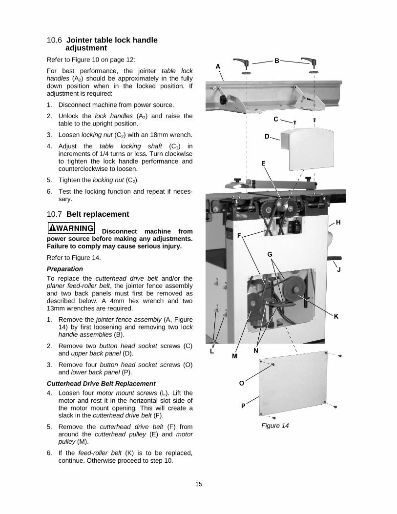
10.6 Jointer table lock handle adjustment
Refer to Figure 10 on page 12:
For best performance, the jointer table lock handles (A2) should be approximately in the fully down position when in the locked position. If adjustment is required:
1. Disconnect machine from power source.
2. Unlock the lock handles (A2) and raise the table to the upright position.
3. Loosen locking nut (C2) with an 18mm wrench.
4. Adjust the table locking shaft (C1) in increments of 1/4 turns or less. Turn clockwise to tighten the lock handle performance and counterclockwise to loosen.
5. Tighten the locking nut (C2).
6. Test the locking function and repeat if neces-sary.
10.7 Belt replacement
Disconnect machine from power source before making any adjustments. Failure to comply may cause serious injury.
Refer to Figure 14.
Preparation To replace the cutterhead drive belt and/or the planer feed-roller belt, the jointer fence assembly and two back panels must first be removed as described below. A 4mm hex wrench and two 13mm wrenches are required.
1. Remove the jointer fence assembly (A, Figure 14) by first loosening and removing two lock handle assemblies (B).
2. Remove two button head socket screws (C) and upper back panel (D).
3. Remove four button head socket screws (O) and lower back panel (P).
Cutterhead Drive Belt Replacement 4. Loosen four motor mount screws (L). Lift the
motor and rest it in the horizontal slot side of the motor mount opening. This will create a slack in the cutterhead drive belt (F).
5. Remove the cutterhead drive belt (F) from around the cutterhead pulley (E) and motor pulley (M).
6. If the feed-roller belt (K) is to be replaced, continue. Otherwise proceed to step 10.
Figure 14
16
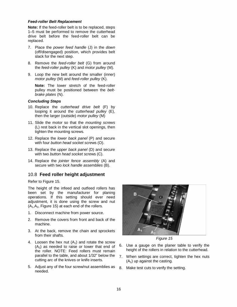
Feed-roller Belt Replacement Note: If the feed-roller belt is to be replaced, steps 1–5 must be performed to remove the cutterhead drive belt before the feed-roller belt can be replaced.
7. Place the power feed handle (J) in the down (off/disengaged) position, which provides belt slack for the next step.
8. Remove the feed-roller belt (G) from around the feed-roller pulley (K) and motor pulley (M).
9. Loop the new belt around the smaller (inner) motor pulley (M) and feed-roller pulley (K).
Note: The lower stretch of the feed-roller pulley must be positioned between the belt-brake plates (N).
Concluding Steps 10. Replace the cutterhead drive belt (F) by
looping it around the cutterhead pulley (E), then the larger (outside) motor pulley (M)
11. Slide the motor so that the mounting screws (L) rest back in the vertical slot openings, then tighten the mounting screws.
12. Replace the lower back panel (P) and secure with four button head socket screws (O).
13. Replace the upper back panel (D) and secure with two button head socket screws (C).
14. Replace the jointer fence assembly (A) and secure with two lock handle assemblies (B).
10.8 Feed roller height adjustment Refer to Figure 15.
The height of the infeed and outfeed rollers has been set by the manufacturer for planing operations. If this setting should ever need adjustment, it is done using the screw and nut (A1,A2, Figure 15) at each end of the rollers.
1. Disconnect machine from power source.
2. Remove the covers from front and back of the machine.
3. At the back, remove the chain and sprockets from their shafts.
4. Loosen the hex nut (A1) and rotate the screw (A2) as needed to raise or lower that end of the roller. NOTE: Feed rollers must remain parallel to the table, and about 1/32” below the cutting arc of the knives or knife inserts.
5. Adjust any of the four screw/nut assemblies as needed.
Figure 15
6. Use a gauge on the planer table to verify the height of the rollers in relation to the cutterhead.
7. When settings are correct, tighten the hex nuts (A1) up against the casting.
8. Make test cuts to verify the setting.
17
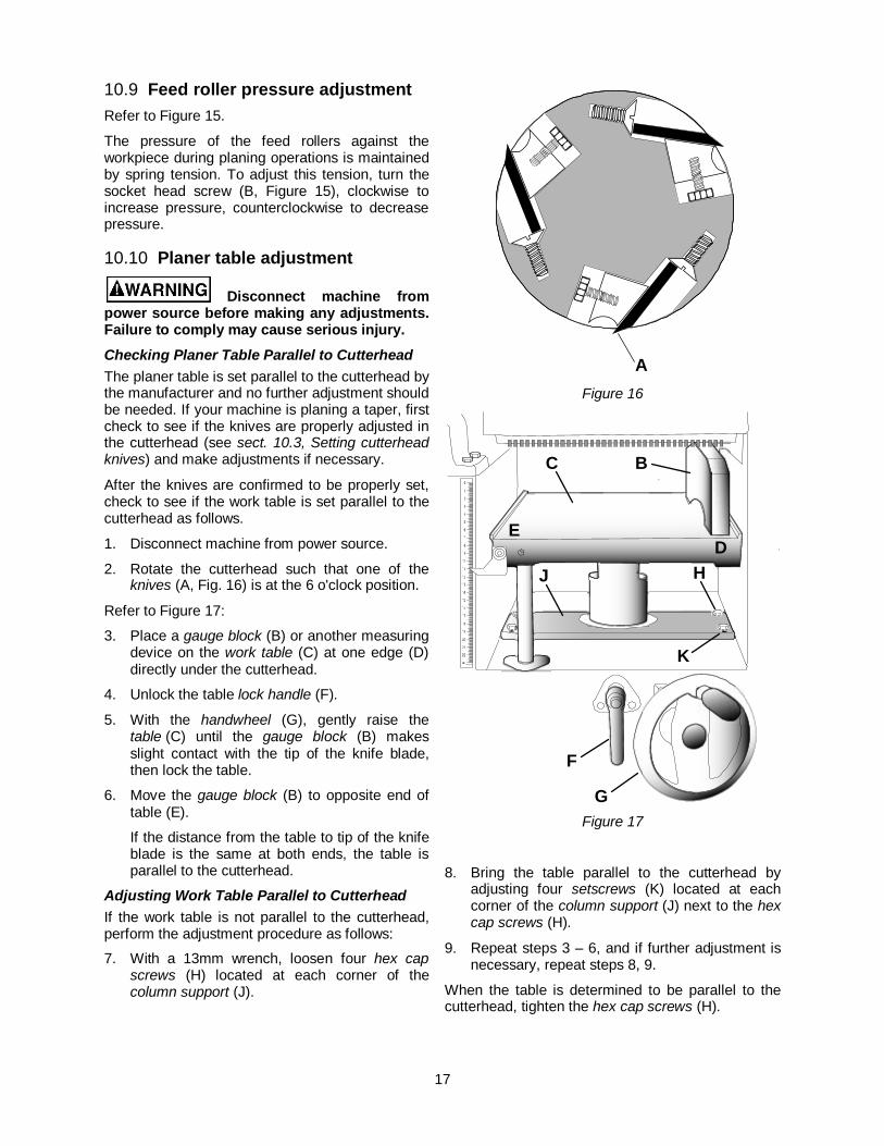
10.9 Feed roller pressure adjustment Refer to Figure 15.
The pressure of the feed rollers against the workpiece during planing operations is maintained by spring tension. To adjust this tension, turn the socket head screw (B, Figure 15), clockwise to increase pressure, counterclockwise to decrease pressure.
10.10 Planer table adjustment
Disconnect machine from power source before making any adjustments. Failure to comply may cause serious injury. Checking Planer Table Parallel to Cutterhead The planer table is set parallel to the cutterhead by the manufacturer and no further adjustment should be needed. If your machine is planing a taper, first check to see if the knives are properly adjusted in the cutterhead (see sect. 10.3, Setting cutterhead knives) and make adjustments if necessary.
After the knives are confirmed to be properly set, check to see if the work table is set parallel to the cutterhead as follows.
1. Disconnect machine from power source.
2. Rotate the cutterhead such that one of the knives (A, Fig. 16) is at the 6 o'clock position.
Refer to Figure 17:
3. Place a gauge block (B) or another measuring device on the work table (C) at one edge (D) directly under the cutterhead.
4. Unlock the table lock handle (F).
5. With the handwheel (G), gently raise the table (C) until the gauge block (B) makes slight contact with the tip of the knife blade, then lock the table.
6. Move the gauge block (B) to opposite end of table (E).
If the distance from the table to tip of the knife blade is the same at both ends, the table is parallel to the cutterhead.
Adjusting Work Table Parallel to Cutterhead If the work table is not parallel to the cutterhead, perform the adjustment procedure as follows:
7. With a 13mm wrench, loosen four hex cap screws (H) located at each corner of the column support (J).
Figure 16
Figure 17
8. Bring the table parallel to the cutterhead by adjusting four setscrews (K) located at each corner of the column support (J) next to the hex cap screws (H).
9. Repeat steps 3 – 6, and if further adjustment is necessary, repeat steps 8, 9.
When the table is determined to be parallel to the cutterhead, tighten the hex cap screws (H).
A
BC
DE
J H
K
F
G
18
11.0 Basic operations 11.1 Dust collection Before initial operation, the machine must be connected to a dust collector.
11.2 Initial startup After the assembly and adjustments are complete, the planer is ready to be tested. Turn on the power supply at the main panel. Press the Start button. Keep your finger on the Stop button in case of a problem. The planer should run smoothly with little or no vibration or rubbing noises. Investigate and correct the source of any problems before further operation.
DO NOT attempt to inves-tigate or adjust the planer while it is running. Wait until the planer is turned off, unplugged and all working parts have come to a complete standstill.
Always wear ANSI-approved safety glasses or goggles when operating the jointer-planer.
11.3 Changing mode of operation When changing the operating mode (planer to jointer and back) the machine must be turned off and at a complete standstill. To change the mode of operation, see sect. 9.1, Jointer to planer setup and sect. 9.2, Planer to jointer setup.
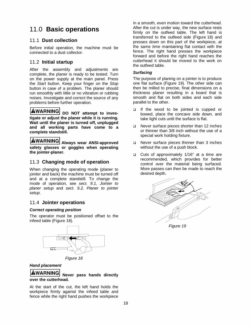
11.4 Jointer operations Correct operating position The operator must be positioned offset to the infeed table (Figure 18).
Figure 18
Hand placement
Never pass hands directly over the cutterhead.
At the start of the cut, the left hand holds the workpiece firmly against the infeed table and fence while the right hand pushes the workpiece
in a smooth, even motion toward the cutterhead. After the cut is under way, the new surface rests firmly on the outfeed table. The left hand is transferred to the outfeed side (Figure 18) and presses down on this part of the workpiece, at the same time maintaining flat contact with the fence. The right hand presses the workpiece forward and before the right hand reaches the cutterhead it should be moved to the work on the outfeed table.
Surfacing The purpose of planing on a jointer is to produce one flat surface (Figure 19). The other side can then be milled to precise, final dimensions on a thickness planer resulting in a board that is smooth and flat on both sides and each side parallel to the other.
If the wood to be jointed is cupped or bowed, place the concave side down, and take light cuts until the surface is flat.
Never surface pieces shorter than 12 inches or thinner than 3/8 inch without the use of a special work holding fixture.
Never surface pieces thinner than 3 inches without the use of a push block.
Cuts of approximately 1/16" at a time are recommended, which provides for better control over the material being surfaced. More passes can then be made to reach the desired depth.
Figure 19

19
Direction of Grain Avoid feeding work into the jointer against the grain (Figure 20). This may result in chipped and splintered edges.
Figure 20
Feed with the grain to obtain a smooth surface, as shown in Figure 21.
Figure 21
Jointing Jointing (or edging) is the process of creating a finished, flat edge surface that is suitable for joinery or finishing (Figure 22). It is also a necessary step prior to ripping stock to width on a table saw.
Never edge a board that is less than 3 inches wide, less than 1/4 inch thick, or 12 inches long, without using a push block.
When edging wood wider than 3 inches, lap the fingers over the top of the wood, extending them back over the fence such that they will act as a stop for the hands in the event of a kickback.
Position the fence (move it forward) to expose only the amount of cutterhead required.
When workpiece is twice the length of the jointer infeed or outfeed table use an infeed or outfeed support.
To edge:
1. Make sure the fence is set to 90°. Double check it with a square.
2. Inspect stock for soundness and grain direction (refer to Direction of grain).
Figure 22 – Surfacing
3. If the board is bowed (curved), place the concave edge down on the infeed table.
4. Set the infeed table for a cut of approx-imately 1/16 inch.
5. Hold the stock firmly against the fence and table, feed the stock slowly and evenly over the cutterhead.
Beveling Beveling an edge is the same operation as edge jointing, except that the fence is tilted to a specified angle.
Make certain material being beveled is over 12 inches long, more than 1/4 inch thick and 1 inch wide.
To bevel:
1. Use a bevel gauge to determine the desired angle. Then set the fence to the same angle.
2. Inspect stock for soundness and grain direction (refer to Direction of Grain).
3. Set the infeed table for a cut of approximately 1/16.
4. If the board is bowed (curved), place the concave edge down on the infeed table.
5. Feed the stock through the cutterhead, making sure the face of the stock is completely flat against the fence and the edge is making solid contact on the infeed and outfeed tables (Figure 23).
For wood wider than 3 inches – hold with fingers close together near the top of the stock, lapping over the board and extending over the fence.

20
For wood less than 3 inches wide – use beveled push blocks and apply pressure toward the fence. Keep fingers near top of push block.
Several passes may be required to achieve the full bevel.
Figure 23 – Beveling
11.5 Planer operations Depth of Cut Thickness planing refers to the sizing of lumber to a desired thickness while creating a level surface parallel to the opposite side of the board. Board thickness that the planer will produce is indicated by the scale and the depth-of-cut gauge (see sect. 9.4, Table height adjustment). Preset the planer to the desired thickness of the finished workpiece using the gauge. The depth-of-cut is adjusted by raising or lowering the planer table (C, Fig. 5) using the handwheel (F, Fig. 5).
The quality of thickness planing depends upon the operator's judgment about the depth of cut.
The depth of cut depends upon the width, hardness, dampness, grain direction and grain structure of the wood.
The maximum thickness of wood that can be removed in one pass is 1/8” for planning operations on workpieces up to 5-1/2” wide. The workpiece must be positioned away from the center tab on the rollercase to cut 1/8”.
The maximum thickness of wood that can be removed in one pass is 1/16” for planing operations on workpieces from 5-1/2” up to 12" wide.
For optimum planing performance, the depth of cut should be less than 1/16”.
The board should be planed with shallow cuts until the work has a level side. Once a level surface has been created, flip the lumber and create parallel sides.
Plane alternate sides until the desired thick-ness is obtained. When half of the total cut has been taken from each side, the board will have a uniform, moisture content and additional drying will not cause it to warp.
The depth of cut should be shallower when the workpiece is wider.
When planing hardwood, take light cuts or plane the wood in thin widths.
Make a test cut with a test piece and verify the thickness produced.
Check the accuracy of the test cut before working on the finished product.
Precautions A thickness planer is a precision
woodworking machine and should be used on good-quality lumber only.
Do not plane dirty boards; dirt and small stones are abrasive and will wear out the blade.
Remove nails and staples. Use the planer to cut wood only.
Avoid knots. Heavily cross-grained wood makes knots hard. Knots can come lose and jam the blade. Any article that encounters planer blades may be forcibly ejected from the planer creating a risk of injury.
Preparing the Work A thickness planer works best when the
lumber has at least one flat surface. Use a jointer to create a flat surface.
Twisted or severely warped boards can jam the planer. Rip the lumber in half to reduce the magnitude of the warp.
The work should be fed into the planer in the same direction as the grain of the wood. Sometimes the wood will change directions in the middle of the board. In such cases, if possible, cut the board in the middle so the grain direction is correct.
Do not plane a board that is less than 6" long. It is recommended that when planing short boards you butt them end to end to avoid kickback and reduce snipe. Feeding the Work The planer is supplied with planer blades mounted in the cutterhead and infeed and outfeed rollers adjusted to the correct height. The planer feed is automatic; it will vary slightly depending on the type of wood.
Infeed Table
Outfeed Table
FenceStock
21
Preparation:
Feed rate refers to the rate at which the lumber travels through the planer.
The operator is responsible for aligning the work so it will feed properly.
Raise or lower the rollercase to get the depth of cut desired.
The surface that the planer produces will be smoother if a shallower depth of cut is used.
Stand on the side that the handle is attached.
Boards longer than 24” should have additional support from free standing material stands. These can be purchased from JET – Stock # 709209. See sect. 17.0, Optional accessories.
Planing 1. Position the workpiece with the face to be
planed on top.
2. Turn the planer on.
3. Turn the power feed on.
4. Rest the board end on the infeed roller plate and direct the board into the planer.
5. Slide the workpiece into the infeed side of the planer until the infeed roller begins to advance the workpiece.
6. Let go of the workpiece and allow the automatic feed to advance the workpiece.
7. Do not push or pull on the workpiece. Move to the rear and receive the planed lumber by grasping it in the same manner that it was fed.
To avoid the risk of injury due to kickbacks, do not stand directly in line with the front or rear of the planer.
8. Do not grasp any portion of the board that has not gone past the outfeed roller.
9. Repeat this operation on all of the boards that need to be the same thickness.
Avoiding Snipe Snipe refers to a depression at either end of the board caused by an uneven force on the cutterhead when the work is entering or leaving the planer.
Snipe will occur when the boards are not supported properly or when only one feed roller is in contact with the work at the beginning or end of the cut.
Precautions for avoiding snipe: Push the board up while feeding the work
until the outfeed roller starts advancing it.
Move to the rear and receive the planed board by pushing it up when the infeed roller loses contact with the board.
When planing more than one board of the same thickness, butt the boards together to avoid snipe.
Make shallow cuts. Snipe is more apparent when deeper cuts are taken.
Feed the work in the direction of the grain. Work fed against the grain will have chipped, splintered edges.

22
12.0 Maintenance 12.1 Blade care
Blades are extremely sharp! Use caution when cleaning
or changing. Failure to comply may cause serious injury!
The condition of the blades will affect the precision of the cut. Observe the quality of the cut that the planer produces to check the condition of the blades.
Dull blades will tear, rather than cut the wood fibers and produce a fuzzy appearance.
Raised grain will occur when dull blades pound on wood that has varying density. A raised edge will also be produced where the blades have been nicked.
When gum and pitch collect on the blades, carefully remove with a strong solvent. Failure to remove gum and pitch build up may result in excessive friction, blade wear and overheating.
When blades become dull, touch up blades. See sect. 12.2, Sharpening the Knives.
12.2 Sharpening knives (straight knives only)
Blades are extremely sharp! Use caution when handling.
Failure to comply may cause serious injury!
1. Disconnect the machine from the power source.
2. Remove the blade guard and belt cover.
3. To protect the infeed table from scratches, partially cover the sharpening stone with paper (Figure 24).
4. Lay the stone on the infeed table.
5. Lower the infeed table and turn the cutterhead by turning the cutterhead pulley. The infeed table height is set properly when the stone's surface is flush with the knife bevel.
6. Keep the cutterhead from rotating by grasping the cutterhead pulley while sliding the stone back and forth across the table.
7. Take the same amount of passes for all three blades.
If the blades have been sharpened and still are not cutting efficiently, trying to touch up the blades further will only cause the formation of a second beveled edge. When this starts to happen, it is time to replace blades with another set. It is recommended to keep a second set of blades on hand so that they may be installed while the first set is being professionally sharpened.
Figure 24
Do NOT attempt to sharpen helical knife inserts! Only rotate the knife once it is dull. If all sides have been rotated properly, dispose of the knife and replace it with a replacement insert. Refer to sect. 10.5, Replacing or rotating knife inserts.
13.0 Lubrication Use a good grade of light grease on the
steel adjusting screws located in the raising and lowering mechanisms of the work tables.
The cutterhead ball bearings are lifetime lubricated and need no further care.

23
14.0 Troubleshooting the JJP-12,JJP-12HH 14.1 Performance troubleshooting – Jointer Trouble Probable Cause Remedy
Finished stock is concave on back end.
Knife is higher than outfeed table. Align cutterhead knives with outfeed table. See sect. 10.3, Setting cutterhead knives.
Finished stock is concave on front end. Outfeed table is higher than knife.
Align cutterhead knives with outfeed table. See sect. 10.3, Setting cutterhead knives.
Chip out. Cutting against the grain. Cut with the grain whenever possible.
Dull knives. Sharpen or replace knives/Rotate knife inserts or replace inserts.
Feeding workpiece too fast. Use slower rate of feed.
Cutting too deeply. Make shallower cuts.
Knots, imperfections in wood. Inspect wood closely for imperfections; use different stock if necessary.
Fuzzy grain. Wood has high moisture content. Allow wood to dry or use different stock.
Dull knives. Sharpen or replace knives/inserts.
Cutterhead slows while operating.
Feeding workpiece too quickly, or applying too much pressure to workpiece.
Feed more slowly, or apply less pressure to workpiece.
“Chatter” marks on workpiece. Knives incorrectly set.
Set knives properly as described in sect. 10.3, Setting cutterhead knives. Check that knife slots are clean and free of dust or debris.
Feeding workpiece too fast. Feed workpiece slowly and consistently.
Uneven knife marks on workpiece.
Knives are nicked, or out of alignment.
Align knives per sect. 10.3, Setting cutterhead knives. Replace nicked knives/Rotate knife inserts.
Table 2
24
14.2 Performance troubleshooting – Planer Trouble Probable Cause Remedy
Snipe
Note: Snipe cannot be eliminated, but can be so minimized as to become negligible.
Table rollers not set properly. Adjust rollers to proper height
Inadequate support of long boards. Support long boards with extension rollers.
Uneven feed roller pressure front to back.
Adjust feed roller tension.
Dull knives. Sharpen knives/Rotate knife inserts.
Lumber not butted properly. Butt end to end each piece of stock as they pass through.
Fuzzy Grain Planing wood with high moisture content.
Remove high moisture content from wood by drying.
Dull knives. Sharpen or replace/Rotate knife inserts.
Torn Grain Too heavy a cut. Adjust proper depth of cut.
Knives cutting against grain. Cut along the grain.
Dull knives. Sharpen knives/Rotate knife inserts.
Rough/Raised Grain Dull knives. Sharpen knives/Rotate knife inserts.
Too heavy a cut. Adjust proper depth.
Moisture content too high. Remove high moisture content from wood by drying.
Rounded, glossy surface
Dull knives. Sharpen or replace knives/Rotate knife inserts or replace.
Feed speed too slow. Increase speed.
Cutting depth too shallow. Increase depth.
Poor feeding of lumber.
Inadequate feed roller pressure. Adjust feed roller tension. If proper tension cannot be achieve, replace feed rollers
Planer bed rough or dirty. Clean pitch and residue, and wax planer table.
Transmission v-belt slipping. Tighten transmission v-belt.
Surface of feed rollers clogged. Clear pitch and residue out of teeth.
Uneven depth of cut side to side.
Knife projection. Adjust knife projection.
Cutterhead not level with bed. Level bed.
Board thickness does not match depth of cut scale.
Depth of cut scale incorrect. Adjust depth of cut scale.
Table 3
25
14.3 Mechanical troubleshooting – Planer/Jointer Trouble Probable Cause Remedy
Chain jumping.
Inadequate tension.
Adjust chain tension.
Sprockets misaligned.
Align sprockets.
Sprockets worn. Replace sprockets.
Machine will not start/ restart or repeatedly trips circuit breaker or blows fuses.
No incoming power.
Verify unit is connected to power, on-button is pushed in completely, and stop-button is disengaged.
Overload automatic reset has not reset
When planer overloads on the circuit breaker built into the motor starter, it takes time for the machine to cool down before restart. Allow unit to adequately cool before attempting restart.
Planer frequently trips.
One cause of overloading trips, which are not electrical in nature, is too heavy a cut. The solution is to take a lighter cut. If too deep a cut is not the problem, then check the amp setting on the overload relay. Match the full load amps on the motor as noted on the motor plate. If the amp setting is correct then there is probably a loose electrical lead. Check amp setting on motor starter.
Building circuit breaker trips or fuse blows.
Verify that planer is on a circuit of correct size. If circuit size is correct, there is probably a loose electrical lead. Check amp setting on motor starter.
Loose electrical connections.
Go through all the electrical on the planer including motor connections, verifying the tightness of each. Look for any signs of electrical arcing which is a sure indicator of loose connections or circuit overload.
Motor starter failure.
Examine motor starter for burned or failed components. If damage is found, replace motor starter. If motor starter looks okay but is still suspect, you have two options: have a qualified electrician test the motor starter for function, or purchase a new starter and establish if that was the problem on changeout
Switch or Motor failure – how to distinguish.
If you have access to a voltmeter, you can separate a starter failure from a motor failure by first, verifying incoming voltage at 220+/-20 and second, checking the voltage between starter and motor at 220+/-20. If incoming voltage is incorrect, you have a power supply problem. If voltage between starter and motor is incorrect, you have a starter problem. If voltage between starter and motor is correct, you have a motor problem.
Motor failure. If electric motor is suspect, you have two options: Have a qualified electrician test the motor for function or remove the motor and take it to a quality electric motor repair shop and have it tested.
Miswiring of the unit.
Double check to confirm all electrical connections are correct and properly tight. The electrical connections other than the motor are pre-assembled and tested at the factory. Therefore, the motor connections should be double checked as the highest probability for error. If problems persist, double-check the factory wiring.
Table 4
26
15.0 Replacement parts To order parts or reach our service department, call 1-800-274-6848 Monday through Friday (see our website for business hours, www.waltermeier.com). Having the Model Number and Serial Number of your machine available when you call will allow us to serve you quickly and accurately.
15.1 Parts List for JJP-12, JJP-12HH
Index No. Part No. Description Size Qty 1 ............... TS-1541031 .............Lock Nut .............................................................M8 .............................. 4 2 ............... JJP12-002 ...............Washer.................................................................................................. 4 3 ............... JJP12-003 ...............Outfeed Table Bracket Shaft .................................................................. 1 4 ............... JJP12-004 ...............Outfeed Table Bracket, Right ................................................................. 1 5 ............... TS-1504121 .............Socket Head Cap Screw .....................................M8x60 ........................ 4 6 ............... JJP12-006 ...............Eccentric Shaft ...................................................................................... 4 7 ............... JJP12-007 ...............Table ..................................................................................................... 2 8 ............... JJP12-008 ...............Cutterhead Guard Assembly (includes #401-426, 9, 10,33) .................... 1 9 ............... JJP12-009 ...............Bracket .................................................................................................. 1 10 ............. TS-1503071 .............Socket Head Cap Screw .....................................M6x30 ........................ 2 11 ............. JJP12-011 ...............Washer...............................................................H12 ............................ 4 12 ............. TS-2342121 .............Lock Nut .............................................................M12 ............................ 4 13 ............. TS-1503051 .............Socket Head Cap Screw .....................................M6x20 ........................ 4 14 ............. JJP12-014 ...............Adjusting Handle ................................................................................... 2 15 ............. JJP12-015 ...............Knob ..................................................................................................... 2 16 ............. JJP12-016 ...............Bracket Screw ....................................................................................... 2 17 ............. JJP12-017 ...............Bracket Screw ....................................................................................... 2 18 ............. JJP12-018 ...............Eccentric Shaft Bracket ......................................................................... 2 19 ............. JJP12-019 ...............Eccentric Shaft Clamp ........................................................................... 2 20 ............. JJP12-020 ...............Table Locking Shaft ............................................................................... 2 21 ............. TS-1540081 .............Hex Nut ..............................................................M12 ............................ 2 22 ............. JJP12-022 ...............Outfeed Table Bracket, Left ................................................................... 1 23 ............. TS-1524021 .............Socket Set Screw ...............................................M8x10 ........................ 8 24 ............. JJP12-024 ...............Plastic Disc .........................................................D6 .............................. 8 25 ............. TS-1490051 .............Hex Cap Screw ..................................................M8x30 ........................ 6 26 ............. TS-1550061 .............Flat Washer ........................................................M8 .............................. 6 27 ............. JJP12-027 ...............Table Support ........................................................................................ 2 28 ............. JJP12-028 ...............Spring.................................................................................................... 2 29 ............. TS-1490021 .............Hex Cap Screw ..................................................M8x16 ........................ 2 30 ............. TS-1540061 .............Hex Nut ..............................................................M8 .............................. 3 31 ............. JJP12-031 ...............Big Cam Wheel ..................................................................................... 1 32 ............. TS-2276081 .............Socket Set Screw ...............................................M6x8 .......................... 1 33 ............. JJP12-033 ...............Cutterhead Guard with Cap ................................................................... 1 34 ............. TS-1524031 .............Socket Set Screw ...............................................M8x12 ........................ 8 61 ............. JJP12-061 ...............Small Cam Wheel .................................................................................. 1 62 ............. JJP12-062 ...............Washer...............................................................H16 ............................ 1 63 ............. JJP12-063 ...............Dust Collector Assembly ........................................................................ 1 64 ............. JJP12-064 ...............Roll Pin...............................................................M5x18 ........................ 1 65 ............. JJP12-065 ...............Shaft ..................................................................................................... 1 66 ............. JJP12-062 ...............Washer...............................................................H16 ............................ 1 67 ............. BB-6205ZZ ..............Bearing...............................................................6205ZZ....................... 2 68 ............. 708821 ....................Knife (Set of 3) * .................................................................................... 1 69 ............. JJP12-069 ...............Knife Locking Bar * ................................................................................ 3 70 ............. JJP12-070 ...............Knife Locking Bar Screw * ................................................................... 15 71 ............. JJP12-071 ...............Cutterhead (Straight Knife) * .................................................................. 1 71A .......... JJP12HH-071A ........Cutterhead, Helical with Inserts ** .......................................................... 1 71B .......... 1791212...................Knife Insert (set of 10) ** ...................................................................... 56

27
Index No. Part No. Description Size Qty 71C .......... JWP208HH-111 .......Knife Insert Screw ** ...........................................#10-32 x 1/2 ............. 56 71D .......... JJ6HH-113 ...............Start Point Screwdriver (not shown) ** ................................................... 2 72 ............. TS-2246122 .............Button Head Socket Screw .................................M6x12 ........................ 4 73 ............. JJP12-073 ...............Belt Cover ............................................................................................. 1 74 ............. JJP12-074 ...............Screw .................................................................................................... 4 75 ............. JJP12-075 ...............Spring.................................................................................................... 4 76 ............. TS-1490021 .............Hex Cap Screw ..................................................M8x16 ........................ 4 77 ............. TS-1540061 .............Hex Nut ..............................................................M8 .............................. 4 78 ............. TS-1491031 .............Hex Cap Screw ..................................................M10x25 ...................... 4 79 ............. TS-1550071 .............Flat Washer ........................................................M10 ............................ 4 80 ............. JJP12-080 ...............Adjusting Washer ................................................................................ 48 81 ............. JJP12-081 ...............Anti-Kickback Finger ............................................................................ 38 82 ............. JJP12-082 ...............Infeed Roller .......................................................................................... 1 83 ............. JJP12-083 ...............Anti-Kickback Shaft ............................................................................... 1 84 ............. JJP12-084 ...............Cutterhead Cover .................................................................................. 1 85 ............. JJP12-085 ...............Cutterhead Bracket, Right ...................................................................... 1 86 ............. TS-1550041 .............Flat Washer ........................................................M6 .............................. 4 87 ............. TS-1503031 .............Socket Head Cap screw .....................................M6x12 ........................ 4 88 ............. JJP12-088 ...............Cutterhead Bracket Cover ..................................................................... 1 89 ............. TS-2246122 .............Button Head Socket Screw .................................M6x12 ........................ 2 90 ............. TS-2331061 .............Cap Nut ..............................................................M6 .............................. 1 91 ............. JJP12-091 ...............Spring.................................................................................................... 1 92 ............. JJP12-092 ...............Stop Pin ................................................................................................ 1 93 ............. JJP12-093 ...............Support Rod .......................................................................................... 1 94 ............. JJP12-094 ...............Outfeed Roller ....................................................................................... 1 95 ............. JJP12-095 ...............Bushing ................................................................................................. 4 96 ............. JJP12-096 ...............Cutterhead Bracket, Left ........................................................................ 1 97 ............. JJP12-097 ...............Wave Washer .....................................................D52 ............................ 2 98 ............. JJP12-098 ...............Retaining Ring ....................................................CLP52 ........................ 2 99 ............. JJP12-099 ...............Washer.................................................................................................. 2 100 ........... JJP12-100 ...............Drive Chain Sprocket ............................................................................. 2 101 ........... JJP12-101 ...............Washer...............................................................WSH10....................... 2 102 ........... TS-1541041 .............Lock Nut .............................................................M10 ............................ 2 103 ........... JJP12-103 ...............Socket Set Screw ...............................................M8x6 .......................... 2 104 ........... JJP12-104 ...............Key.....................................................................PLN6x16 .................... 1 105 ........... JJP12-105 ...............Spindle Pulley........................................................................................ 1 106 ........... JJP12-106 ...............Washer...............................................................D52 ............................ 2 131 ........... JJP12-131 ...............Carriage Bolt ......................................................N12x65....................... 1 132 ........... JJP12-132 ...............Square Washer ..................................................................................... 1 133 ........... JJP12-133 ...............Bushing ................................................................................................. 1 135 ........... JJP12-135 ...............Bearing...............................................................BRG80101 ................. 1 136 ........... JJP12-136 ...............Chain Wheel .......................................................................................... 1 137 ........... TS-2342121 .............Lock Nut .............................................................M12 ............................ 1 138 ........... TS-2284302 .............Pan Head Screw ................................................M4x30 ........................ 2 139 ........... TS-1541021 .............Lock Nut .............................................................M6 .............................. 2 140 ........... TS-1550041 .............Flat Washer ........................................................M6 .............................. 2 141 ........... JJP12-141 ...............Safety Switch......................................................................................... 1 142 ........... JJP12-142 ...............Safety Switch Bracket ............................................................................ 1 143 ........... TS-1541001 .............Lock Nut .............................................................M4 .............................. 2 144 ........... TS-1550041 .............Washer...............................................................M6 .............................. 4 145 ........... TS-1540041 .............Hex Nut ..............................................................M6 .............................. 2 146 ........... JJP12-146 ...............Safety Switch Rocker............................................................................. 1 147 ........... JJP12-147 ...............Safety Switch Rocker Shaft ................................................................... 1 148 ........... TS-1503061 .............Socket Head Cap Screw .....................................M6x25 ........................ 2 151 ........... JJP12-151 ...............Bolt........................................................................................................ 4 152 ........... TS-1540061 .............Hex Nut ..............................................................M8 .............................. 4 153 ........... JJP12-153 ...............Outfeed Table Lock Handle ................................................................... 1
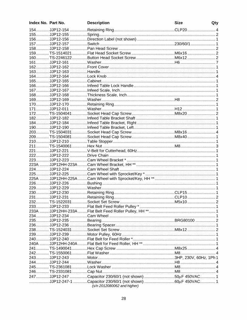
28
Index No. Part No. Description Size Qty 154 ........... JJP12-154 ...............Retaining Ring ....................................................CLP20 ........................ 4 155 ........... JJP12-155 ...............Spring.................................................................................................... 2 156 ........... JJP12-156 ...............Direction Label (not shown) ................................................................... 1 157 ........... JJP12-157 ...............Switch ................................................................230/60/1 ..................... 1 158 ........... JJP12-158 ...............Pan Head Screw ................................................................................... 2 159 ........... TS-1514021 .............Flat Head Socket Screw .....................................M6x16 ........................ 2 160 ........... TS-2246122 .............Button Head Socket Screw .................................M6x12 ........................ 2 161 ........... JJP12-161 ...............Washer...............................................................H6 .............................. 7 162 ........... JJP12-162 ...............Front Cover ........................................................................................... 1 163 ........... JJP12-163 ...............Handle................................................................................................... 1 164 ........... JJP12-164 ...............Lock Knob ............................................................................................. 4 165 ........... JJP12-165 ...............Cabinet.................................................................................................. 1 166 ........... JJP12-166 ...............Infeed Table Lock Handle ...................................................................... 1 167 ........... JJP12-167 ...............Infeed Scale, Inch .................................................................................. 1 168 ........... JJP12-168 ...............Thickness Scale, Inch ............................................................................ 1 169 ........... JJP12-169 ...............Washer...............................................................H8 .............................. 2 170 ........... JJP12-170 ...............Retaining Ring ....................................................................................... 1 171 ........... JJP12-011 ...............Washer...............................................................H12 ............................ 1 172 ........... TS-1504041 .............Socket Head Cap Screw .....................................M8x20 ........................ 2 182 ........... JJP12-182 ...............Infeed Table Bracket Shaft .................................................................... 1 184 ........... JJP12-184 ...............Infeed Table Bracket, Right ................................................................... 1 190 ........... JJP12-190 ...............Infeed Table Bracket, Left ...................................................................... 1 203 ........... TS-1504031 .............Socket Head Cap Screw .....................................M8x16 ........................ 4 209 ........... TS-1504081 .............Socket Head Cap Screw .....................................M8x40 ........................ 1 210 ........... JJP12-210 ...............Table Stopper ........................................................................................ 1 211 ........... TS-1540061 .............Hex Nut ..............................................................M8 .............................. 3 221 ........... JJP12-221 ...............V-Belt for Cutterhead, 60Hz ................................................................... 1 222 ........... JJP12-222 ...............Drive Chain ........................................................................................... 1 223 ........... JJP12-223 ...............Cam Wheel Bracket * ............................................................................ 1 223A ........ JJP12HH-223A ........Cam Wheel Bracket, HH ** .................................................................... 1 224 ........... JJP12-224 ...............Cam Wheel Shaft .................................................................................. 1 225 ........... JJP12-225 ...............Cam Wheel with Sprocket/Key * ............................................................ 1 225A ........ JJP12HH-225A ........Cam Wheel with Sprocket/Key, HH ** .................................................... 1 226 ........... JJP12-226 ...............Bushing ................................................................................................. 1 229 ........... JJP12-229 ...............Washer.................................................................................................. 1 230 ........... JJP12-230 ...............Retaining Ring ....................................................CLP15 ........................ 1 231 ........... JJP12-231 ...............Retaining Ring ....................................................CLP10 ........................ 2 232 ........... TS-1522031 .............Socket Set Screw ...............................................M5x10 ........................ 2 233 ........... JJP12-233 ...............Flat Belt Feed Roller Pulley * ................................................................. 1 233A ........ JJP12HH-233A ........Flat Belt Feed Roller Pulley, HH ** ......................................................... 1 234 ........... JJP12-234 ...............Cam Wheel ........................................................................................... 1 235 ........... JJP12-235 ...............Bearing...............................................................BRG80100 ................. 2 236 ........... JJP12-236 ...............Bearing Spacer ...................................................................................... 1 238 ........... TS-1524031 .............Socket Set Screw ...............................................M8x12 ........................ 2 239 ........... JJP12-239 ...............Motor Pulley, 60Hz ................................................................................ 1 240 ........... JJP12-240 ...............Flat Belt for Feed Roller *....................................................................... 1 240A ........ JJP12HH-240A ........Flat Belt for Feed Roller, HH ** .............................................................. 1 241 ........... TS-1490041 .............Hex Cap Screw ..................................................M8x25 ........................ 4 242 ........... TS-1550061 .............Flat Washer ........................................................M8 .............................. 4 243 ........... JJP12-243 ...............Motor ..................................................................3HP, 230V, 60Hz, 1Ph 1 244 ........... JJP12-244 ...............Washer...............................................................H8 .............................. 4 245 ........... TS-2361081 .............Lock Washer ......................................................M8 .............................. 4 246 ........... TS-2331081 .............Cap Nut ..............................................................M8 .............................. 4 247 ........... JJP12-247 ...............Capacitor 230/60/1 (not shown) ..........................50μF 450VAC ............. 1 ................. JJP12-247-1 ............Capacitor 230/60/1 (not shown) ..........................60μF 450VAC ............. 1 (s/n 2012080062 and higher)

29
Index No. Part No. Description Size Qty 248 ........... JJP12-248 ...............Shaft ..................................................................................................... 1 249 ........... TS-2361101 .............Lock Washer ......................................................M10 ............................ 1 250 ........... TS-1540071 .............Hex Nut ..............................................................M10 ............................ 1 251 ........... JJP12-251 ...............Small Motor Pulley ................................................................................. 1 252 ........... JJP12-252 ...............Plate * ................................................................................................... 1 252A ........ JJP12HH-252A ........Plate, HH ** ........................................................................................... 1 253 ........... TS-2206601 .............Hex Cap Screw ..................................................M6x60 ........................ 1 254 ........... TS-1482051 .............Hex Cap Screw ..................................................M6x25 ........................ 2 255 ........... TS-1540041 .............Hex Nut ..............................................................M6 .............................. 6 256 ........... TS-1550041 .............Flat Washer ........................................................M6 .............................. 2 257 ........... JJP12-257 ...............Rubber Handle ...................................................................................... 1 288 ........... JJP12-288 ...............Indicator ................................................................................................ 1 289 ........... TS-2246122 .............Button Head Socket Screw .................................M6x12 ........................ 1 290 ........... TS-1524031 .............Socket Set Screw ...............................................M8x12 ........................ 1 291 ........... JJP12-291 ...............Table Guide Bar .................................................................................... 1 292 ........... TS-1503051 .............Socket Head Cap screw .....................................M6x20 ........................ 2 293 ........... JJP12-293 ...............Guide Bar Bracket ................................................................................. 2 294 ........... TS-1550041 .............Flat Washer ........................................................M6 .............................. 2 295 ........... TS-1540041 .............Hex Nut ..............................................................M6 .............................. 2 297 ........... TS-1524031 .............Socket Set Screw ...............................................M8x12 ........................ 1 298 ........... JJP12-298 ...............Indicator Seat ........................................................................................ 1 299 ........... TS-2246202 .............Button Head Socket Screw .................................M6x20 ........................ 1 300 ........... JJP12-300 ...............Screw .................................................................................................... 2 301 ........... JJP12-301 ...............Cover .................................................................................................... 1 302 ........... JJP12-302 ...............Washer.................................................................................................. 2 303 ........... JJP12-303 ...............Nut ........................................................................................................ 2 304 ........... JJP12-304 ...............Locking Bar ........................................................................................... 1 305 ........... JJP12-305 ...............Locking Shoe......................................................................................... 1 306 ........... JJP12-306 ...............Crank Handle ........................................................................................ 1 307 ........... JJP12-307 ...............Hand Wheel .......................................................................................... 1 308 ........... TS-1504031 .............Socket Head Cap Screw .....................................M8x16 ........................ 1 312 ........... JJP12-154 ...............Retaining Ring ....................................................CLP20 ........................ 1 313 ........... JJP12-313 ...............Retaining Ring ....................................................................................... 1 314 ........... JJP12-314 ...............Washer.................................................................................................. 1 315 ........... JJP12-315 ...............Crank Bar .............................................................................................. 1 316 ........... TS-2246122 .............Button Head Socket Screw .................................M6x12 ........................ 2 317 ........... TS-1540041 .............Flat Washer ........................................................M6 .............................. 2 318 ........... JJP12-318 ...............Bevel Gear ............................................................................................ 2 319 ........... JJP12-319 ...............Retaining Ring ....................................................CLP35 ........................ 1 320 ........... JJP12-320 ...............Bearing...............................................................BRG80202 ................. 1 321 ........... JJP12-321 ...............Bevel Gear Bracket ............................................................................... 1 322 ........... TS-1550061 .............Flat Washer ........................................................M8 .............................. 5 323 ........... TS-1490061 .............Hex Cap Screw ..................................................M8x35 ........................ 2 324 ........... JJP12-324 ...............Thread Rod ........................................................................................... 1 325 ........... JJP12-325 ...............Bolt.....................................................................M6x40 ........................ 1 326 ........... TS-1540041 .............Hex Nut ..............................................................M6 .............................. 1 327 ........... TS-1490061 .............Hex Cap Screw ..................................................M8x35 ........................ 2 329 ........... TS-1550061 .............Flat Washer ........................................................M8 .............................. 2 330 ........... JJP12-330 ...............Thread Rod Bracket .............................................................................. 1 331 ........... JJP12-331 ...............Column Support .................................................................................... 1 332 ........... TS-1550061 .............Flat Washer ........................................................M8 .............................. 4 333 ........... TS-1524051 .............Socket Set Screw ...............................................M8x20 ........................ 4 334 ........... TS-1490061 .............Hex Cap Screw ..................................................M8x35 ........................ 4 335 ........... JJP12-335 ...............Column.................................................................................................. 1 336 ........... TS-149105 ...............Hex Cap Screw ..................................................M10x35 ...................... 2 337 ........... TS-2361101 .............Lock Washer ......................................................M10 ............................ 2 338 ........... JJP12-338 ...............Planer Table .......................................................................................... 1

30
Index No. Part No. Description Size Qty 339 ........... JJP12-339 ...............Scale Ring Assembly, Inch .................................................................... 1 368 ........... JJP12-368 ...............Hinge Pin .............................................................................................. 2 369 ........... JJP12-369 ...............Square Nut .........................................................M8 .............................. 2 370 ........... TS-1541021 .............Lock Nut .............................................................M6 .............................. 2 371 ........... JJP12-371 ...............Fence Mounting Bracket ........................................................................ 2 372 ........... TS-1504031 .............Socket Head Cap Screw .....................................M8x16 ........................ 2 374 ........... TS-1514021 .............Flat Head Socket Screw .....................................M6x16 ........................ 2 376 ........... JJP12-376 ...............Fence Support, Right ............................................................................. 1 377 ........... JJP12-377 ...............Nylon Washer ...................................................................................... 10 378 ........... JJP12-378 ...............Carriage Bolt ......................................................M8x25 ........................ 2 379 ........... TS-2246122 .............Button Head Socket Screw .................................M6x12 ........................ 6 380 ........... TS-1550041 .............Flat Washer ........................................................M6 .............................. 6 381 ........... JJP12-381 ...............Cutterhead Cover .................................................................................. 1 382 ........... TS-1541021 .............Lock Nut .............................................................M6 .............................. 4 383 ........... TS-1503031 .............Socket Head Cap Screw .....................................M6x12 ........................ 4 384 ........... JJP12-384 ...............Fence Bracket, Left ............................................................................... 1 385 ........... JJP12-385 ...............Locking Handle ...................................................................................... 3 386 ........... JJP12-386 ...............Special Washer ..................................................................................... 2 387 ........... JJP12-387 ...............Fence .................................................................................................... 1 388 ........... JJP12-388 ...............Fence Support, Left ............................................................................... 1 389 ........... JJP12-389 ...............Fence Bracket, Right ............................................................................. 1 390 ........... JJP12-390 ...............Fence Scale .......................................................................................... 1 391 ........... JJP12-391 ...............Complete Fence Assembly .................................................................... 1 392 ........... JPT410-392 .............Locking Tube (s/n 2010110096 and higher) ........................................... 2 393 ........... JPT410-393 .............Set Screw ...........................................................M8x50 ........................ 2 394 ........... JPT410-394 .............Nut .....................................................................M8 .............................. 2 395 ........... JJP12-071-01 ..........Adjusting Screw ..................................................M6x20 ........................ 6 401 ........... ................................Lock Knob (RE: JJP12-008)................................................................... 1 402 ........... ................................Lead Screw (RE: JJP12-008)................................................................. 1 403 ........... ................................Spring (RE: JJP12-008) ......................................................................... 1 404 ........... ................................Bracket for Guard (RE: JJP12-008)........................................................ 1 405 ........... TS-1550031 .............Washer...............................................................5 ................................. 2 406 ........... TS-1541011 .............Lock Nut .............................................................M5 .............................. 2 407 ........... TS-2331081 .............Cap Nut .............................................................M8 .............................. 2 408 ........... ................................Locking Support (RE: JJP12-008) .......................................................... 1 409 ........... TS-2311081 .............Hex. Nut .............................................................M8 .............................. 1 410 ........... ................................Linkage Bar (RE: JJP12-008) ................................................................ 1 412 ........... ................................End Cap (RE: JJP12-033) ..................................................................... 2 413 ........... ................................Guard Plate Cover (RE: JJP12-033) ...................................................... 1 414 ........... ................................Lock Plate (RE: JJP12-033) ................................................................... 1 415 ........... ................................Knob (RE: JJP12-033) ........................................................................... 1 416 ........... ................................Nylon Bolt (RE: JJP12-033) ................................................................... 1 417 ........... TS-1541021 .............Lock Nut .............................................................M6 .............................. 1 418 ........... ................................Bracket (RE: JJP12-033) ....................................................................... 1 419 ........... TS-1540031 .............Hex. Nut ............................................................M5 .............................. 2 420 ........... TS-1540041 .............Nut .....................................................................M6 .............................. 2 421 ........... TS-1541021 .............Lock Nut .............................................................M6 .............................. 2 422 ........... ................................Nylon Washer .....................................................6 ................................. 2 423 ........... ................................Shaft-M6 (RE: JJP12-033) ..................................................................... 1 424 ........... ................................Shaft-M8 (RE: JJP12-033) ..................................................................... 1 426 ........... TS-1550041 .............Washer...............................................................6 ................................. 2 * Indicates Straight Cutterhead Model Only ** Indicates Helical Cutterhead Model Only Items without part numbers are only available in the indicated assembly.

31
15.2 Infeed Table Assembly – Exploded View

32
15.3 Outfeed Table Assembly – Exploded View

33
15.4 Cutterblock Assembly – Exploded View

34
15.5 Base Assembly – Exploded View

35
15.6 Motor Assembly – Exploded View

36
15.7 Planer Table Assembly – Exploded View

37
15.8 Fence Assembly – Exploded View
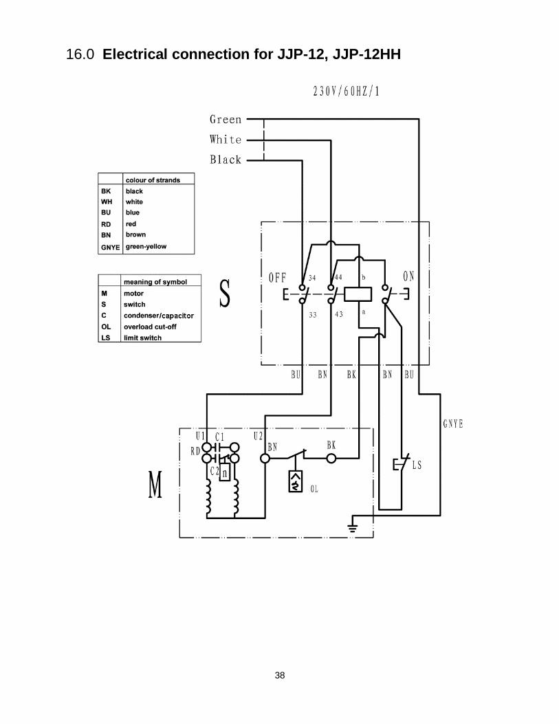
38
16.0 Electrical connection for JJP-12, JJP-12HH

39
17.0 Optional accessories These items are purchased separately.
Stock No Description 708821 .............Replacement Knives for JJP-12 Jointer-planer (set of 3) 1791212 ...........Replacement Knife Inserts for JJP-12HH Jointer-Planer (set of 10) 709209 .............Roller Stand, 12.5” wide 708118 .............JMB-UMB Universal Mobile Base

40
427 New Sanford Road LaVergne, Tennessee 37086
Phone: 800-274-6848 www.jettools.com