Embed Size (px)
Citation preview

DFTS2 v8.x
MAN90111400 March 2008: v8.xx
1
OPERATING INSTRUCTIONS for ADVANCED DIGITAL FAST TUNER SYSTEM 2 - DFTS2
These instructions apply to the Advanced Digital Fast Tuner System 2 (DFTS2) supplied by CPI Canada integrated with an S-, C- or Ku-band communications klystron. For general enquiries call CPI Canada Customer Support at (905) 877 0161 or e-mail: marketing @cmp.cpii.com.
Introduction. _______________________________________________________________________ 2
General. ___________________________________________________________________________ 2
Installation. ________________________________________________________________________ 2
Startup ____________________________________________________________________________ 3
New in this version: _________________________________________________________________ 3
Safety Information.__________________________________________________________________ 4
System Overview. ___________________________________________________________________ 4
Controller Input.____________________________________________________________________ 4
System Parameters and Channel Data. _________________________________________________ 5
Issuing Commands.__________________________________________________________________ 5
Firmware Revision Summary._________________________________________________________ 5
Error Codes________________________________________________________________________ 5
Tuning Notes _______________________________________________________________________ 7
Disposal ___________________________________________________________________________ 8
APPENDIX 1: Command Set Summary Table. __________________________________________ 9
APPENDIX 2: Parameter Range & Details _____________________________________________ 10
APPENDIX 3: Full Command Descriptions. ___________________________________________ 13
APPENDIX 4: Felix Tuning Utility Instructions. ________________________________________ 22

DFTS2 v8.x
MAN90111400 March 2008: v8.xx
2
OPERATING INSTRUCTIONS: DIGITAL FAST TUNER SYSTEM.
Introduction. DFTS2 is an updated, enhanced-capability electronically controlled tuner system. As it supports up to 99 channels of frequency/position data, klystrons using it carry the option suffix “-D99”, as opposed to the “-D50” characteristic of the original DFTS. DFTS2 is fully backward compatible into systems using the prior DFTS system. When using DFTS2 to replace an earlier system, see the “installation” section below for how to use some of the DFTS2 advanced features in your existing KPA. Improvements included in DFTS2 compared to the earlier model:
• 99 channels of stored frequency/position data that can be segregated into two tuning databases. • Elimination of the personality module and associated connectors for enhanced reliability. • Use of non-volatile FLASH memory throughout. • Software control of motor current allowing the tuner to detect and recover from changes in
operating torque. • Addition of status LED’s for first-order troubleshooting in a KPA without a terminal program. • RoHS-consistent build. Some early units will not be fully lead-free: call CPI with questions.
General. These instructions apply to the Digital Fast Tuner System 2 (DFTS2) supplied by CPI Canada integrated with an S-, C- or Ku-band communications klystron. For general enquiries call CPI Canada Customer Support at (905) 877 0161 or e-mail: [email protected].
Installation.
CAUTION:
MAKE SURE THERE IS NO POWER APPLIED WHEN CONNECTING OR DISCONNECTING THE DFTS2 CONTROLLER.
Klystron Installation. 1. The controller is contained within the klystron’s tuning module. There is no second box to attach. 2. Once the klystron is properly installed in the KPA, attach the lead to the 15-pin input.
Turn-On. Be sure that the 24V DC supply is within the correct voltage range (22-25V). The DFTS2 will go through its turn-on sequence: consult the KPA manual for any system messages. DFTS2 operating mode is determined by setting parameter 101, the DFTS Compatibility Mode Parameter. This parameter is summarized below.
Parameter Number 101 Set DFTS2 firmware into the desired DFTS compatibility mode.
• In the “DFTS2 Native Mode”, error codes and status messages have extra detail, the product has the capacity for 99 channels of stored settings, and the channel database can be divided into two sets for different tuning patterns.
• In DFTS compatible mode, the tuning system responds in the same way as the prior DFTS system v7.05. Some new features are available, such as software control of motor current.

DFTS2 v8.x
MAN90111400 March 2008: v8.xx
3
• The HSTS compatible mode is useful in MCL and PTI/Vertex/Aydin amplifiers that were optimized for the Thales/Thomson HSTS. Apart from the “wake-up string”, this mode is the same as DFTS compatible mode.
Parameter Value 0 : DFTS backward-compatible mode 1 : DFTS 2 Native Mode 2 : Thales / Thomson HSTS compatibility mode (V1.6)
Example Command Result Q10100000 set DFTS Compatibility mode (default) Q10100001 set DFTS 2 Native Mode Q10100002 set Thales / Thomson HSTS compatibility mode (V1.6)
Query Response Meaning: active mode N101 N10100000 DFTS Compatibility mode N101 N10100001 DFTS 2 Native Mode N101 N10100002 Thales / Thomson HSTS compatibility mode
Startup DFTS2 Parameter 101 for DFTS backward compatibility Parameters are stored in flash memory so at cold startup and at controller reset the previous DFTS compatibility mode will be in effect.
Startup Definition Table
DFTS2 Parameter 101 Value = 0 or 2
DFTS2 Parameter 101 Value = 1
Channel Database allocation
01 - 50
Determined by the setting of DFTS2 parameter number 065
A suitable cable must be used to connect a personal computer to the DFTS2 while using the KPA’s 24VDC supply to power the unit. CPI Canada makes cables for this purpose (764058), and they are supplied with spare klystrons. Check your packing in which you received your products.
New in this version: The first release of DFTS2 firmware was Revision 8.03. Compared to the earlier DFTS, the most significant changes are:
• Elimination of the separate controller by incorporating it into the tuning module. • Elimination of the personality module and therefore all associated memory check and copy
commands. • Increase of channel memory to 99 channels. • Addition of a second database (for dual tuning patterns), with separate interpolation parameters.
The sizes of the databases are configurable with any split, including 99 channels in one database and 0 in the other.

DFTS2 v8.x
MAN90111400 March 2008: v8.xx
4
• Software control of driver current, which allows the tuner to adapt itself if there are changes in required operating torque.
• Incorporation of a “boot-loader” feature to allow firmware updates via personal computer. See “Revision Summary” below for description of firmware changes.
Safety Information. There are quickly-moving high-torque motors in the tuning mechanism of the klystron, and users must be careful to keep fingers etc away from these parts when they could move. The voltages present in the tuner system are all 24V nominal or less.
System Overview. The Digital Fast Tuner System 2 is a motorized, microprocessor controlled, tuning system. Each cavity of the klystron is independently tuned by a stepper motor, which is controlled in a closed-loop fashion by the integrated controller. The control signals are issued in response to commands sent to the DFTS2 through its RS232/RS422 port. The tuner attached to the klystron has four to six motor axes, depending on model, each axis comprising a stepper motor, an encoder, an optical switch to aid in finding a reference position, and a precision actuator set. Within the tuner’s memory, the relevant stored information comprises: • System parameters (e.g. acceleration rate, current level, travel speed) that define the motion control. • Interpolation coefficients, frequency limits, and other set-up information for that klystron. • Channel data for up to 99 channels in 1 or 2 databases. Each channel record contains the frequency
and requisite position data. Dual database function may not be supported by your KPA. • Channel change counter, serial number information. The controller is inside the tuner module cover, and attaches to the tuning hardware by means of connectors. There is a connector for each motor and each encoder, plus one connector for all of the optical switches.
Controller Input. The input connector is a DB15 socket for DC input power as well as RS232 and RS422 connections. The pin assignments are given below.
Pin Description 1, 9 GND
2 RS232 Rx 3 RS232 Tx 4 Not Connected 5 Not Connected 6 RS232 0V
7 & 14 OV DC Supply 8 & 15 +24V DC Supply
10 RS422 Rx A 11 RS422 Rx B 12 RS422 Tx A 13 RS422 Tx B

DFTS2 v8.x
MAN90111400 March 2008: v8.xx
5
Input Requirements. RS232, RS422: 9600bps, 8 bits, no parity, 1 stop bit. ASCII-coded alphanumeric string. DC 24VDC +1V, -2V
DAMAGE MAY OCCUR TO THE EMI SUPPRESSING FERRITES AT OR ABOVE 26V.
System Parameters and Channel Data. The system parameters are organized in the klystron controller Flash memory as an array of 16-bit integers. Also contained in memory is channel data for each tunable channel, and this comprises position data for each axis, as well as the frequency assignment for the channel. See Appendix 2 for the list of System Parameters and some explanation of their function.
Issuing Commands. General. Commands are issued through the RS232/422 port. A controller within a KPA system will typically conduct communications with the port, but for system configuration it may be more convenient to use either a terminal emulation program on a personal computer, or to use CPI’s communication application Felix_XP2 that runs under Microsoft Windows 2000/XP. Older versions of Felix are available to run under other, older Microsoft operating systems: advice from CPI will be required to use some DFTS2 features using these older programs. Felix_XP2 is available upon request to any user of CPI’s DFTS2 products, subject to normal agreements on usage and further distribution. See Appendix 4 for instruction on its use.
Firmware Revision Summary. V 8.0 The first release of DFTS2 firmware provided to OEMs and end-users. In DFTS emulation mode this is equivalent to DFTS v7.05 with v7.05A (Thales HSTS compatible) and 4- and 6-cavity also included and selectable.
V 8.04 Bootloader function changed. Prior version went into bootloader mode upon receipt of any ASCII character at start-up. Sometimes this would unintentionally happen due to transients at power on. In 8.04, this was changed to respond only to a spacebar at 19200 baud.
Error Codes The following is a list of error codes the controller may return. If no error is reported after a command is issued, the controller will return the "E00" code:

DFTS2 v8.x
MAN90111400 March 2008: v8.xx
6
CODE MEANING
CODE: DFTS2 MODE
(Parameter 101 = 1)
CODE: DFTS or HSTS MODE
(Parameter 101 = 0 or 2) SYSTEM READY (OK) E00 E00 EMPTY CHANNEL E03 E03 PLUNGER POSITION LIMIT E04 E04 SYNTAX ERROR E05 E05 PLUNGER NOT AVAILABLE E07 E07 PROTECTED INSTRUCTION E08 E08 LIMIT SWITCH REACHED E09 E09 MISSING EEPROM E10 E10 EEPROM FAIL E11 E11 CORRUPTED EEPROM E12 E12 DISPLACEMENT TIMEOUT E13 E13 CALC ERROR E14 E14 CHANNEL CHANGE TIMEOUT E15 E13 HOME MOVE TIMEOUT E16 E13 UNSUCCESSFUL CHANNEL CHANGE. STALLING WAS DETECTED AND THE MOTION WAS STOPPED.
E21 E13
SUCCESSFUL CHANNEL CHANGE AFTER RECOVERY FROM STALLING.
E22 E13
Power Up sequence Upon power up, the tuner goes to the home position and then will assume the last active channel settings, if enabled through parameters 60 and 61. This takes between five and 40 seconds depending on model (S-band takes much longer than C- or Ku-band) and whether it is configured for simultaneous or low-power (sequential) zeroing of all axes. The controller will then transmit the version number of the installed firmware. The contents of this string are dependent on the setting of the DFTS Compatibility Parameter, 101. (See Appendix 2 for more information on parameters). This allows system designers to differentiate CPI versus other manufacturers’ products.
Precision of Home Position. The home position is a zero-reference position. It is found by moving the axes downwards until an optical switch is triggered, which means that HOME has been found within about 0.020”. The system then searches for the next encoder index mark, which locates HOME to the exact encoder position. As an indicator of system precision, there are typically 1600 encoder steps per revolution, and a revolution translates to 0.031” (0.80mm) for Ku-band, so one encoder step is 0.000 019” (0.5µm).
Command Set Summary 1. Command codes are not case sensitive. 2. All error codes are terminated with a carriage return character (0x13). 3. All return strings are terminated with a carriage return character (0x13). 4. All user entries should be terminated with a carriage return character (0x13).

DFTS2 v8.x
MAN90111400 March 2008: v8.xx
7
LED Status Indicators Condition Green Blue Red
Normal Operating Mode ON if last command was good: see below for errors
Blinking: 1sec on/off
ON or blinking if last command was bad: see below for errors
Bootloader waiting to connect Blinking: 250msec on/off
ON OFF
Bootloader: waiting for a command or downloading new firmware.
OFF OFF ON
E00 on any command (latch) ON Blinking: 1sec on/off
OFF
Any error code generated (except for Motion Recovery or timeout) (latch)
OFF Blinking: 1sec on/off
ON
Motion Recovery error code generated (latch until error code is reported or 6 good channel changes later)
ON if channel achieved, OFF if not achieved.
Blinking: 1sec on/off
BLINKING 1sec on/off
Timeout code generated BLINKING 1sec on/off
BLINKING 1sec on/off
BLINKING 1sec on/off
Working on valid command BLINKING 1 sec on/off
Blinking: 1sec on/off
OFF
SEQUENTIAL (LOW-POWER) GOING HOME BLINKING 250ms on/off
Blinking fast 250ms on/off
ON
NORMAL GOING HOME BLINKING 250ms on/off ON ON
Tuning Notes The klystron tuning is the same as for the manually tuned equivalent klystron with one very important exception. The final direction for tuning each cavity prior to memorizing has to be made in the UPWARDS direction in frequency. This is opposite to what most users are used to with C-band and Ku-band klystrons. Note that mechanical backlash is significant so that a downward movement in cavity frequency must go beyond the target and return, with backlash of about 400 to 600 points in each direction. It is recommended that tuning be done from the front panel of the KPA if the model is equipped with this option, especially where the KPA manufacturer has devised a system to compensate for backlash for customer convenience. However, many KPAs are not so equipped, and the easiest way to retune is to use CPI Canada’s “FELIX” utility.
Tuning Using Felix. Please see Appendix 4 for detailed instructions. 1. You need an interface cable to draw 24V power from the KPA while providing an RS232 connection
between KPA and the klystron. CPI Canada can provide such a cable (764058), check your packaging to see if you have one already. Otherwise, see the section “Controller Inputs” for the pin assignments for the controller.
2. Start Felix, and set the COM port correctly for your computer. 3. Use pull-down menu [Tuning]- [Show Channel Database] 4. Select a channel by left clicking on it, then right click, and choose [Change to this channel]. You can
also double-click any channel to immediately tune to that channel. 5. If there is no channel tuned to the frequency of interest, you can interpolate to that frequency by
clicking in the frequency field of the [Channel / Database Edit] area, enter the frequency of interest, and press <return>.
6. Click on the button that is marked [Read Cavity Positions]. 7. You can now trim the channel by selecting a step size, then clicking in the space for a given cavity,
and use the up and down arrows on your keyboard to move the tuning up and down. 8. For taking the backlash out, use a step size of 100 or 200.

DFTS2 v8.x
MAN90111400 March 2008: v8.xx
8
9. For fine trimming, a step size of 10 is generally fine enough. 10. THIS IS VERY IMPORTANT. Make sure you finish tuning each cavity with an UPWARD
movement. 11. THIS IS VERY IMPORTANT. Before memorizing a channel, press the button [Read Cavity
Positions], then memorize it
Tuning Using HyperTerminal or similar. NOTE: This procedure is possible, but will take some time and is a little cumbersome. A better alternative is to contact CPI Canada to obtain the latest version of the FELIX interface utility, or to obtain advice from a technician familiar with the product on how to proceed. The commands you will need are: • A1984 (password access), • Ccc to tune to channel cc, (where cc represents channel number in the range 00 to 99) • Sn (to select a cavity where n is cavity number in the range 1 – 6 depending on the klystron model), • Q001xxxxx (to select a step size for tuning via U and D commands, where xxxxx represents a five-
digit number typically less than 00200), • U (to tune cavity n up in frequency by xxxxx points), • D (to tune cavity n down in frequency by xxxxx points), • R to read the current positions, • Rcc to read the current contents of channel cc. • Mcc to memorise the current state as channel cc. • Ffffff.f to interpolate to fffff.f MHz (where fffff.f is the channel frequency in MHz with leading zero
characters as required e.g. 02120.0). See Appendix 1 for a complete list of available commands and a brief description of how they work.
Disposal For disposal instructions, contact CPI Canada: [email protected]
DFTS2 v8.x
MAN90111400 March 2008: v8.xx
9
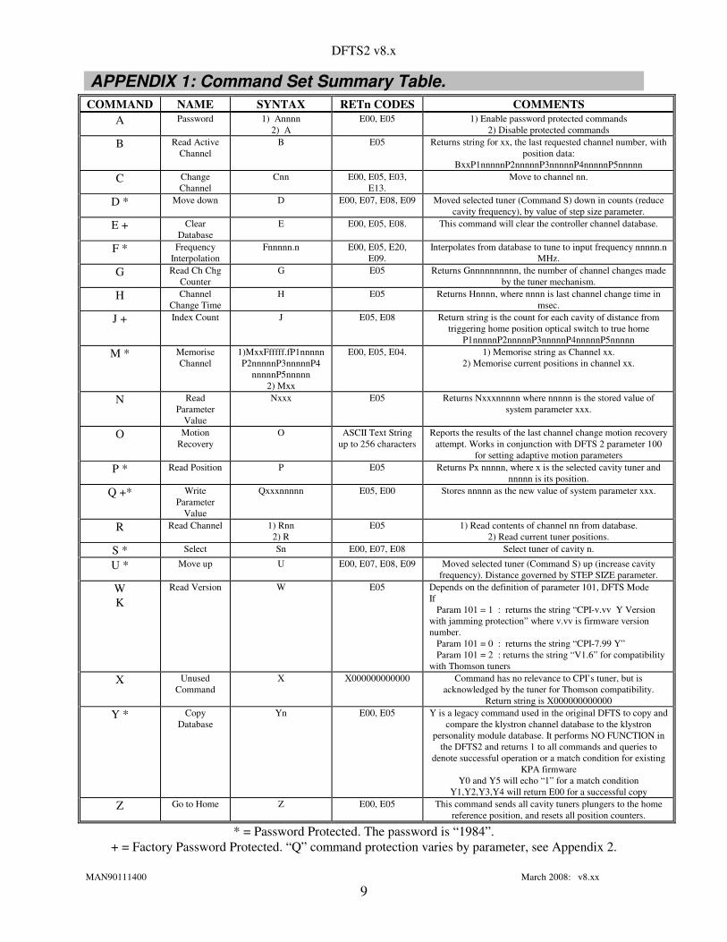
APPENDIX 1: Command Set Summary Table. COMMAND NAME SYNTAX RETn CODES COMMENTS
A Password 1) Annnn 2) A
E00, E05 1) Enable password protected commands 2) Disable protected commands
B Read Active Channel
B E05 Returns string for xx, the last requested channel number, with position data:
BxxP1nnnnnP2nnnnnP3nnnnnP4nnnnnP5nnnnn C Change
Channel Cnn E00, E05, E03,
E13. Move to channel nn.
D * Move down D E00, E07, E08, E09 Moved selected tuner (Command S) down in counts (reduce cavity frequency), by value of step size parameter.
E + Clear Database
E E00, E05, E08. This command will clear the controller channel database.
F * Frequency Interpolation
Fnnnnn.n E00, E05, E20, E09.
Interpolates from database to tune to input frequency nnnnn.n MHz.
G Read Ch Chg Counter
G E05 Returns Gnnnnnnnnnn, the number of channel changes made by the tuner mechanism.
H Channel Change Time
H E05 Returns Hnnnn, where nnnn is last channel change time in msec.
J + Index Count J E05, E08 Return string is the count for each cavity of distance from triggering home position optical switch to true home
P1nnnnnP2nnnnnP3nnnnnP4nnnnnP5nnnnn M * Memorise
Channel 1)MxxFfffff.fP1nnnnn P2nnnnnP3nnnnnP4
nnnnnP5nnnnn 2) Mxx
E00, E05, E04. 1) Memorise string as Channel xx. 2) Memorise current positions in channel xx.
N Read Parameter
Value
Nxxx E05 Returns Nxxxnnnnn where nnnnn is the stored value of system parameter xxx.
O Motion Recovery
O ASCII Text String up to 256 characters
Reports the results of the last channel change motion recovery attempt. Works in conjunction with DFTS 2 parameter 100
for setting adaptive motion parameters P * Read Position P E05 Returns Px nnnnn, where x is the selected cavity tuner and
nnnnn is its position. Q +* Write
Parameter Value
Qxxxnnnnn E05, E00 Stores nnnnn as the new value of system parameter xxx.
R Read Channel 1) Rnn 2) R
E05 1) Read contents of channel nn from database. 2) Read current tuner positions.
S * Select Sn E00, E07, E08 Select tuner of cavity n.
U * Move up U E00, E07, E08, E09 Moved selected tuner (Command S) up (increase cavity frequency). Distance governed by STEP SIZE parameter.
W K
Read Version W E05 Depends on the definition of parameter 101, DFTS Mode If Param 101 = 1 : returns the string “CPI-v.vv Y Version with jamming protection” where v.vv is firmware version number. Param 101 = 0 : returns the string “CPI-7.99 Y” Param 101 = 2 : returns the string “V1.6” for compatibility with Thomson tuners
X
Unused Command
X X000000000000 Command has no relevance to CPI’s tuner, but is acknowledged by the tuner for Thomson compatibility.
Return string is X000000000000 Y * Copy
Database Yn E00, E05 Y is a legacy command used in the original DFTS to copy and
compare the klystron channel database to the klystron personality module database. It performs NO FUNCTION in
the DFTS2 and returns 1 to all commands and queries to denote successful operation or a match condition for existing
KPA firmware Y0 and Y5 will echo “1” for a match condition
Y1,Y2,Y3,Y4 will return E00 for a successful copy Z Go to Home Z E00, E05 This command sends all cavity tuners plungers to the home
reference position, and resets all position counters.
* = Password Protected. The password is “1984”. + = Factory Password Protected. “Q” command protection varies by parameter, see Appendix 2.

DFTS2 v8.x
MAN90111400 March 2008: v8.xx
10
APPENDIX 2: Parameter Range & Details
Param No.
Name Value Range
Details
001 Step Size 5 to 65535 This defines the number of micro-steps executed by the D or U command. Values smaller than 5 will not yield good results due to backlash and motor inertia. For large steps
(coarse tuning) use a typical value of 100 to 200. For fine tuning: 10 usually works best. 002 Travel Speed 500 to
5000 Travel speed value: This value determines the travel speed in pulses per second (Hz).
Allowed values: 500-5000Hz. The higher the value, the faster the travel speed. If the value is too high, one or more of the motors may stall. DFTS2 will then recover by altering
motion control parameters, reporting E21 or E22. Use command “O” to diagnose. 003 Home Speed 500 to
5000 Home speed value: This value determines the travel speed in pulses per second (Hz).
Allowed values: 500-5000Hz. The higher the value, the faster the travel speed. If the value is too high, one or more of the motors may stall. DFTS2 will then recover by altering
motion control parameters, reporting E23 or E24. Use command “O” to diagnose. 004 Acceleration
step size 0 to19 Acceleration step: defines how smooth is the acceleration curve when travelling from
channel to channel. A small value would yield faster travel between channel to channel, but coarse acceleration curve. A large value would yield slower travel between channel to
channel with a smooth acceleration curve. Smooth acceleration is required for systems with a large torque requirement. If the acceleration value is too small for a large torque
Klystron tuner, one or more of the motors may stall. DFTS2 will then recover by altering motion control parameters, reporting E23 or E24. Use command “O” to diagnose.
005 Compen- sation
1 to 32767 Compensation (number of encoder steps used for belt compensation) – Compensation is required to correct for mechanical backlash. It is activated only in one direction. In a
typical system there are 1600 encoded position per revolution, therefore a value of 1200 would yield a ¾ revolution compensation span. The smaller the compensation value, the faster is the channel-to-channel change time (when used in the compensation direction).
The compensation must be greater than the total system backlash 006 * Mechanical
Position Limit 1 to 32676 Mechanical Position Limit: Software uses this value to prevent motion beyond a certain
limit point. If the user attempts to move to a channel that contains positions above this limit, no motion will take place and an error code (“E09 Software Limit Reached”) is
returned. This parameter is set based on the mechanical limit of the tuner assembly. For example if the travel span for the tuner is 10 revolutions and the encoders provide 1600
points per revolution, the limit should be set to 16,000 points. 007 * No. of
cavities 4 to 6 Number of klystron cavities.
008 * Fmin 1 to 65535 Fmin – The minimum frequency tuned by the controller defined in MHz integer units. 009 * Fmax 1 to 65535 Fmax – The maximum frequency tuned by the controller defined in MHz integer units. 010 * Ch Ch Count 00 Lower 16-bit value of the channel change count – this is the LS part of a 32-bit system
parameter that is used to count the number of times the controller changed channels. 011 * Ch Ch Count 00 Upper 16-bit value of the channel change count – this is the MS part of a 32-bit system
parameter that is used to count the number of times the controller changed channels. 012 Position error
window 1 to 65535 Defines the maximum deviation from the desired target position that will not result in
motion. For example: If parameter 012 is set to 5 and the memory setting for CH01, P1 is 5000 and its actual position is between 4995 and 5005, the command C01 will result in no motion. In this way, unimportant position errors will not cause an attempt to reset position
if the same channel is requested again. Typical values for this parameter are 3 to 10. 013 Linear Tune
Range 0 to 65535 The interpolation F command will linearly interpolate between two tuned channels that
straddle the target frequency, provided those two channels are spaced less than nnnn.n MHz apart. eg a value of 05000 corresponds to 500.0 MHz.
014 * Home UP move
0 to 65535 This defines the distance that the tuner will move UP before moving DOWN to HOME. For this parameter, 12800 corresponds to one revolution. Recommended: 37000.
015 * Smart Home 0 = off 1 = on
When enabled (recommended), the tuner moves UP (by 014 value) before seeking HOME if the optical switches are triggered, i.e. if the tuner is close to the HOME position already.
If the optical switch is clear, no UP movement takes place. 016 Sequential
Zero 0=disabled 1=enabled
When enabled, the first HOME command after start-up is performed by zeroing (going to home) with one cavity at a time. This reduces current draw during the first few seconds
after powering on the KPA, which facilitates KPA power management. 017 Start-Up
Delay 0 to 900 The value of this parameter is a delay time in seconds between the end of sequential
zeroing and assuming the last active channel (if enabled via parameters 060 and 061).

DFTS2 v8.x
MAN90111400 March 2008: v8.xx
11
018 * Ch Change timeout
2 to 30 Channel Change Timeout. Value is number of seconds to report: default is 3 seconds for 5 or 6 cavity, 10 seconds for 4 cavity.
019 * Home Timeout
2 to 30 Channel change timeout. Value is number of seconds to report: default is 10 seconds.
020 to 024 *
A (See note 1,3)
0 to 65535 A coefficients for Cavity 1 to Cavity 5 respectively, used in frequency interpolation for 1st database
025 to 029 *
B (See note 1,3)
0 to 65535 B coefficients for Cavity 1 to Cavity 5 respectively, used in frequency interpolation for 1st database
030 to 034 *
C (Notes 1,2,3)
0 to 65535 C coefficients for Cavity 1 to Cavity 5 respectively, used in frequency interpolation for 1st database
020 to 025 *
A (note 1,3) 0 to 65535 A coefficients for Cavity 1 to Cavity 6 respectively, used in frequency interpolation on 6 cavity klystrons for 1st database.
026 to 031 *
B (note 1,3) 0 to 65535 B coefficients for Cavity 1 to Cavity 6 respectively, used in frequency interpolation on 6 cavity klystrons for 1st database
032 to 037 *
C (note 1,2,3) 0 to 65535 C coefficients for Cavity 1 to Cavity 6 respectively, used in frequency interpolation on 6 cavity klystrons for 1st database.
050 * Klystron S. No.
0 to 65535 Klystron (board) Serial number : the parameter value is set by the manufacturer during the product configuration phase (prior to shipment).
051 * Controller S. No.
0 to 65535 Controller serial number: the parameter value is set by the manufacturer during the product configuration phase (prior to shipment).
052 * Controller Model
0 to 65535 Controller Model: the parameter value is set by the manufacturer during the product configuration phase (prior to shipment).
053 * Klystron Model
0 to 65535 Klystron Model Number: the parameter value is set by the manufacturer during the product configuration phase (prior to shipment).
054 Comms mode 0 to 65535 Communication mode selection: system configuration parameter was added to select either the RS232 or the RS422 interface, now irrelevant since v5.9 as both are always on.
055 * Encoder Logic
0 to 65535 External/Internal Optical encoder Logic selection: Factory option for future upgrade. Value = 255: Selects external HP logic encoder Logic (default)
Value = 0: Selects the internal FPGA logic optical encoder Logic 060 * Active Seek 0 to 65535 If this signature is set to 0xAA along with Parameter 061=0x55, the controller will travel
to the last active channel on power up. For any other value, following power up the controller will travel to the home position and remain there.
Value=170: Travel to last active channel on power up if Parameter 061=85 061 * Active Seek 0 to 65535 If this signature is set to 0x55 along with Parameter 060=0xAA, the controller will travel
to the last active channel on power up. For any other value, following power up, the controller will travel to the home position and remain there.
Value=85 : Travel to last active channel on power up if Parameter 060=170 062 Klystron S/N
(hi) 0 to 65535 Hi order 8 bits for the klystron serial number
063 Klystron S/N (lo)
0 to 65535 Lo order 8 bits for the klystron serial number
065 Set/Read database size
0 to 99 Sets or reads the size of the 1st database (0) from the pool of 99 channels . The remainder is the size of the 2nd database (1) N065: reads the current size of database (0) and Q065xxxxx: sets the size of database (0) Database (1) is assigned whatever channels remain from the pool of 99 after this parameter is set. The database split can be changed at anytime without losing tuning data.
067 Set/Read Active
database
0 or 1 Sets the currently active channel database 0 : sets the 1st database, (0) as active 1 : sets the 2nd database, (1) as active
068 Set/Read Sequential
channel change (first
database)
0 or 1 Enable or disables sequential channel change on the 1st database ONLY. When enabled, each cavitiy moves to the new channel sequentially rather than simoultaneously in order to
reduce power consumption where channel change time is not as high a priority 0 : disables sequential channel change 1 : enables sequential channel change
069 Set/Read
Sequential ch change
(2nd database)
Enable or disables sequential channel change on the 2nd database only. When enabled, each cavity moves to the new channel sequentially rather than simultaneously in order to
reduce power consumption where channel change time is not as high a priority 0 : disables sequential channel change 1 : enables sequential channel change

DFTS2 v8.x
MAN90111400 March 2008: v8.xx
12
070 to 074 *
A (See note 1,3)
0 to 65535 A coefficients for Cavity 1 to Cavity 5 respectively, used in frequency interpolation for 2nd database
076 to 080 *
B (note 1,3) 0 to 65535 B coefficients for Cavity 1 to Cavity 5 respectively, used in frequency interpolation on 5 cavity klystrons for 2nd database
082 to 086 *
C (note 1,3) 0 to 65535 C coefficients for Cavity 1 to Cavity 5 respectively, used in frequency interpolation on 5 cavity klystrons for 2nd database
070 to 075 *
A (See note 1,3)
0 to 65535 A coefficients for Cavity 1 to Cavity 6 respectively, used in frequency interpolation for on 6 cavity klystrons for 2nd database
076 to 081 *
B (note 1,3) 0 to 65535 B coefficients for Cavity 1 to Cavity 6 respectively, used in frequency interpolation on 6 cavity klystrons for 2nd database
082 to 087 *
C (note 1,3) 0 to 65535 C coefficients for Cavity 1 to Cavity 6 respectively, used in frequency interpolation on 6 cavity klystrons for 2nd database
088 to 093
Current Setting for cavity 1-6
Factory Set Current setting for Cavity 1 to Cavity 6 respectively. Values: 1000 to 3000 representing peak current values in [mA]
1.000A to 3.000A respectively. Typical motors rated at 1000 max. 094 to
099 Hold Current
Setting for cavity 1-6
Factory Set Hold Current setting for Cavity 1 to Cavity 6 respectively. Values: 1000 to 3000 representing peak current values in [mA]
1.000A to 3.000A respectively. Recommend 200mA max. 100 Channel
Change Motion
Recovery Mode
0 to 5 Motion fault detection is controlled using parameter 100. 0 - works as before, no detection of stalling or jamming. 1 - Detect stalling and stop after it's detection. Report error E21. 2 - Detect motion fault and try to recover from it by decreasing travel speed (parameter 002). If the DFTS 2 recovers, it will print E22 in response to the channel change command. If it can not recover after 10 attempts, it will report E21. 3 - Detect motion fault and try to recover from it by increasing the current setting for the stalling motor. Current increases in steps of 200mA from its initial value. 4 – DFTS 2 Intelligent Recovery. The DFTS 2 checks if the travel speed is too high and lowers it to the appropriate value. It also checks the current setting and increases it up to 1.6A. If the channel change command still fails after those changes, it tries to recover by alternating methods 2 and 3. 5 – DFTS 2 Interleaved Recovery. The DFTS 2 tries to recover by alternating methods 2 and 3. This parameter is used in conjunction with the O command for reporting the results of the last motion recovery event.
101 DFTS Compatibility
Mode
0, 1 or 2 DFTS Compatibility Mode 0 - DFTS compatibility mode 1 - DFTS2 Native Mode 2 - Thales \ Thomson compatibility mode (V1.6)
* = Factory Password required to write to this parameter. Others require User Password (1984) NOTES 1. To maintain maximum processing speed and minimise memory usage, negative interpolation coefficients are
entered in raw 16-bit signed integer format (16-bit complement notation). E.g.: -1 = 65535, -2 = 65534, -3 = 65533 etc.
Any negative coefficient –n between –1 and –32,767 is computed and entered numerically as (65536-n). 2. The C coefficient is internally scaled down by a factor of 1000. This is done in order to accommodate decimal
coefficient numbers (as required by the interpolation algorithm). For example a value of 0.034 is entered as an integer value of 34, and a value of -0.023 would be entered as an integer value of –23 translating to an entry of 65513 (see note 1 above for entering negative numbers).
3. The specific memory allocation for interpolation coefficients depends on the model of the DFTS2 tuner assembly. Five cavity tuners allocate coefficients parameters from 020 - 034 inclusive for database (0) and 070-084 for database (1). Six cavity tuners allocate coefficient parameters from 020 - 037 inclusive for database (0) and 070-087 for database (1). For this reason, care must be taken when manually setting interpolation coefficient parameters to ensure the proper parameter is being accessed for the tuner assembly being used. CPI recommends using the Felix_XP2 utility (available free of charge to OEMs and CPI DFTS2 customers) for setting these and all other controller parameters on 5 and 6 cavity DFTS2 units.

DFTS2 v8.x
MAN90111400 March 2008: v8.xx
13
APPENDIX 3: Full Command Descriptions. General Notes: 1. Command codes are not case sensitive. 2. Command responses are for DFTS 2 native mode except where noted. 3. All error codes are terminated with a carriage return character (0x13). 4. All return strings are terminated with a carriage return character (0x13). 5. All user entries should be terminated with a carriage return character (0x13). Command: Password protection (A) 1. Syntax: Annnn 2. Syntax: A Where nnnn is a numerical ASCII password of the range: 0000-9999. Acknowledgments: E00, E05 Description: 1. Used to activate the password-protected commands. 2. Used to disable all protected commands. There are two levels of password protection. The first level is guarded by the USER/OEM password and the second level is guarded by the Factory password. Command Protection: No password protection commands are: A, C, R, W, H, B, Z, N, G, X, K,O. User password protected commands are: S, U, D, M, F, Y, P. Factory access only to: E, J Parameter Protection: No Password: No write access for system parameters. Parameters are read-only. User Password: Write access is allowed for parameters 1-5, 12, 13, 54. Factory password: Write access is allowed for all parameters
Command: Select Plunger (S) - password protected. 1. Syntax: Sn Where n is a numerical ASCII plunger number of the range: 0-9. Acknowledgements: E00, E08, E07. Description: Select the current (active) plunger. This command is used along with the D and U commands for moving individual plungers during manual tuning of Cavity positions.
Command: Move Up (U) - password protected Syntax: U

DFTS2 v8.x
MAN90111400 March 2008: v8.xx
14
Acknowledgments: E00, E08, E05, E09. Description: This command will cause the selected active plunger to move away from the home position (up in frequency). The amount of travel initiated by each execution of the 'U' command is determined by the value STEP SIZE parameter (see Parameter definition for details).
Command: Move Down (D) - password protected 1. Syntax: D Acknowledgments: E00, E08, E05, E09. Description: This command will cause the selected active plunger (see the 'S' command for plunger selection) to move down: toward the home position. The amount of travel initiated by each execution of the 'D' command is determined by the value STEP SIZE parameter (see Parameter definition for details).
Command: Change Channel (C) 1. Syntax: Cnn Where nn is the channel number in a numerical ASCII format of the range: 01-99. (01 – 50 with DFTS Compatibility Mode = 0 or 2). Acknowledgements: E00, E05, E03, E13. Description: This command sends the controller to the requested channel settings. Currently this command supports 99 channel presets.
Command: Memorize Channel (M) - password protected. 1. Syntax: MxxFfffff.fP1nnnnnP2nnnnnP3nnnnnP4nnnnnP5nnnnn 2. Syntax: Mxx Where: xx is the channel number to memorize represented as numerical ASCII string of the range: 01-99. (01 – 50 with DFTS Compatibility Mode = 0 or 2). nnnnn is the position value for each plunger in channel xx represented as a numerical ASCII string of the range: 00000-99999 (see description). fffff.f is frequency associated with channel to be memorized, represented as a numerical ASCII string of the range: 00000.0-99999.0 (see description) Acknowledgments: E00, E05, and E04.

DFTS2 v8.x
MAN90111400 March 2008: v8.xx
15
Description: 1. This command memorizes the supplied plunger positions and frequency information into the
database under the xx channel entry. Note that the range for position is limited by the POSITION LIMIT parameter and the entered frequency range is limited by the FMAX and FMIN parameters value. An 'E04' acknowledgement is generated in either case in which the allowed ranges are violated.
2. When the 'Mnn' command is used the controller will memorize the current physical locations (i.e. corresponding to the active channel) into the nn channel. In General this command should used to store the results of an interpolation run or a manual tuning session to the database.
Command: Read Position/Channel (R) 1. Syntax: Rnn 2. Syntax: R Where nn is a numerical ASCII string representing the channel number in the range of: 01-99 (01 – 50 with DFTS Compatibility Mode = 0 or 2). Return String: CxxFfffff.fP1nnnnnP2nnnnnP3nnnnnP4nnnnnP5nnnnn Where: xx is the active (current) channel number represented as a numerical ASCII string of the range: 01-99 (01 – 50 with DFTS Compatibility Mode = 0 or 2). nnnnn is the plunger/memory position value represented as a numerical ASCII string of the range: 00000-99999 fffff.f is frequency associated with the active (current), represented as a numerical ASCII string of the range: 00000.0-99999.0 (see description) Acknowledgments: E05, or the Return string. Description: The 'Rnn' command reads the memorized channel information for channel nn. This command is used to read the entire channel information from the controller database memory. The 'R' command is used to obtain the current physical position of each plunger as being read from the optical encoders. There are three special cases for which the ‘R’ command does not return a specific channel number. For any of these cases the return string shown above will start with C00. This will occur whenever a frequency interpolation command (F), Up (U) or Down (D) command was issued prior to the ‘R’ command. Essentially, whenever plunger positions are moved from a known position to a new position (using F, U or D), the channel number is no longer valid. The new cavity positions assume the designation of Channel 00, and is referred to as the ‘active channel’.

DFTS2 v8.x
MAN90111400 March 2008: v8.xx
16
Format extension note: Occasionally, the system may overshoot the home position by a single step (due to backlash or belt elasticity). In order to handle this possibility, the read position format was extended to handle negative numbers. For example, assume after travelling to the home position plunger 2 happens to be 1 step below the home position (while the others are exactly on the home position), reading the encoder positions will yield the string: C00F00000.0P10000P2-0001P300000P400000P500000
Command: Read Version number (W) or (K) 1. Syntax: W, K Return string : based on the setting of parameter 101 Parameter 101 string response
0 "CPI-7.99 Y” 1 "CPI-n.nn Y” 2 “v1.6”
where n.nn is the controller firmware revision number Acknowledgement: E05 or return String. Description: This command reads the firmware level, n.nn, of the controller during run time. The suffix x is equal to Y in all cases in order to provided backward compatibility with DFTS KPA firmware in the field. It has application for DFTS 2 at this time.
Command: Channel Change time (H) 1. Syntax: H Return string: "Hnnnn" Where nnnn is the time measured by the controller for the last channel change sequence. Acknowledgement: E05 or return String. Description: This command returns the travel time for the last channel change. The value is measured in milliseconds.
Command: Frequency Interpolation (F) - Password Protected 1. Syntax: Fnnnnn.n where nnnnn.n is the desired frequency represented as an ASCII string of the range: 00000.0 - 99999.9 (see description). Acknowledgement: E00, E05, E20, E09.

DFTS2 v8.x
MAN90111400 March 2008: v8.xx
17
Description: This command interpolates the channel settings for a new frequency. The results are copied to the active channel, and the controller proceeds to move to the resultant channel settings. An error is returned if the interpolated position values exceed the limit set by the POSITION LIMIT parameters or if the user attempts to interpolate a frequency which does not reside in the allowed range defined by the FMIN and FMAX parameters. The interpolation algorithm works as follows: upon receiving the Fnnnnn.n command where nnnnn.n is the desired frequency in MHz, the controller searches the existing database for the requested frequency. If the channel already exists the controller will simply travel to the existing channel. If the frequency is not found in the database, the controller will verify that the requested frequency is within the allowed range above Fmin and below Fmax (an “out of range” error code will be relayed back in the case of range violation). Then the controller will proceed to find the nearest distance neighbors channels to the requested frequency. If the distance between the two neighbor channels is smaller than that defined by parameter 13, the new Channel position will calculated using simple linear interpolation independently for each cavity. In case the distance is larger than the value defined by parameter 13, the following algorithm is used (scaling support for the math is required since the frequencies are internally stored as long unsigned integers, for example, 13.7123GHz is stored and computed as 137123):
POSnew=a+(b*(Fnew-Fmin))+ (c*((Fnew-Fmin)^2))
where a, b and c are the parameters 20 - 34 mentioned in appendix 2, and Fmin is defined as parameter #008 (bandwidth minimum starting frequency). Once this command is issued, the resultant values are sent to the active channel and the controller will move to the computed positions. The interpolation square law algorithm works accurately for the coefficient range between +10,000 and –10,000. The ABC coefficients are stored as 16-bits signed integers (see parameter section). The maximum and minimum allowed values are –32,767 and +32,767 respectively.
Note: When the interpolation command is used, the accuracy of tuning depends entirely on the accuracy of the tuned channel data used by the interpolation algorithm. If the klystron is correctly tuned at the two closest channels, which are used in the calculation, and these channels are within 100MHz of each other and straddle the target frequency, then reasonably accurate tuning occurs. The parabolic interpolation algorithm - used when there are no customer-tuned channels in the range defined for linear interpolation - is intended to aid set-up and to speed accurate tuning. Its results are NOT expected to provide the specified bandwidth, gain slope, etc.
Command: Read Active channel (B) 1. Syntax: B Return String: BxxF00000.0P1nnnnnP2nnnnnP3nnnnnP4nnnnnP5nnnnn Where: xx is the last called channel number with the range: 01-99 nnnnn are the active channel position values. (01–50 with DFTS Compatibility Mode = 0,2).

DFTS2 v8.x
MAN90111400 March 2008: v8.xx
18
Acknowledgement: E05, or Return String. Description: This command reads out the active channel values (as stored in memory).
Command: Go to HOME position (Z) 1. Syntax: Z Acknowledgement: E00, E05. Description: This command sends all plungers to the home position, and resets all position counters. How it works is governed by the Smart Home parameter 015, and the Home Upward Move parameter 014. On the first Z command after power-up (v6.92 and later), it is also governed by parameter 016 Sequential Zero and 017 Start-Up Delay. The following sequence takes place with all axes simultaneously if Sequential Zero is disabled, and serially (one at a time, to reduce initialisation current) if Sequential Zero is enabled. After initialisation power up, Z command logic is unaffected by values of parameters 016 and 017: all five motors move simultaneously. Phase 1: ensuring the axes are clear of the Home Position. If the tuner is close to home, such that the optical switches can “see” a target within their window, then the tuner will move those cavities forward by the amount specified in parameter 014 so that the targets clear the switches. This happens whatever the value of parameter 015 may be. If the tuner is not close to home, then the movement is governed by the smart home feature. If smart home is disabled (see parameter 015) then forward movement takes place as per parameter 014. If smart home is enabled, then no forward movement takes place. Phase 2: finding rough home. The axes are now driven back (down in frequency) until the optical switches trip. This is approximately the home position, within about a half-revolution of the motor shaft. Phase 3: Fine Home position. In firmware versions prior to 6.8, the motors continue to drive the tuners back (down in frequency), until the index mark is found on the optical encoder disk. In V6.8 and later, the motor reverses to find the Home position index mark in the other direction. Phase 4: Seeking Last Channel (all axes simultaneously). In the case of a Home Command initiated by powering on the unit, the tuner will return to the last active channel if the values of parameters 060 and 061 are set such that Active Channel Seek is enabled. The default is to enable this feature before the product leaves the factory, a disabled active channel seek is useful when setting up the klystron or performing engineering tests. If Sequential Zero is enabled, then the tuner only seeks the last active channel after an elapsed time defined by Parameter 017.

DFTS2 v8.x
MAN90111400 March 2008: v8.xx
19
Command: Clear Database (E) Factory Password Protected. 1. Syntax: E Acknowledgement: E00, E05, E08. Description: This command will clear the controller. This command should be used only for initialization of new units.
Command: Read parameter (N) 1. Syntax: Nxxx Where: xxx is the parameter number represented by an ASCII string of the range: 001-101. Return String: Nxxxnnnnn where: xxx is the parameter number represented by an ASCII string of the range: 001-101 nnnnnn is the parameter current value of the range: 00000-65535 Acknowledgement: E05 or Return String. Description: The N command is used to read back the value of a system parameter.
Command: Write parameter (Q) – password protected 1. Syntax: Qxxxnnnnnn Where: xxx is the parameter number represented by an ASCII string of the range: 001-101 nnnnn is the new parameter value of the range: 00000-65535. Acknowledgement: E05 or E00 Description: The Q command is used to write a new value into any system parameter. Parameters can be written only after password protection is removed, according the following rule: User Password: Write access is allowed for parameters 1-5, 12, 13, 54. Factory password: Write access is allowed for all parameters.
Command: Read Channel change counter (G) 1. Syntax: G Return String: "Gnnnnnnnnnn" Acknowledgement: E05 or return string. Description: This command will return a 32-bit parameter, which stands for the number of channel changes performed by the controller. To maintain compatibility with the existing parameter structure this 32-bit value is

DFTS2 v8.x
MAN90111400 March 2008: v8.xx
20
stored as two 16-bit values defined as read-write parameters 010 (Low Word) and 011 (High Word). This allows the factory to initialise the starting value of the channel change counter.
Command: Copy databases (Yn) – password protected OBSOLETE -- This command does nothing on DFTS2 It will return a 1 denoting successful or matching operation or parameters for each of the following commands: 1. Syntax: Y0 2. Syntax: Y1 3. Syntax: Y2 4. Syntax: Y3 5. Syntax: Y4 6. Syntax: Y5 Return String: always returns "1" for DFTS compatibility indicating successful operation Acknowledgement: E05, E00, or return string ( “1” ). Only included for backward compatibility with existing KPA firmware expecting results from DFTS database copy and compare commands. DFTS2 returns all such commands as successful or compare = true.
Command: Read Plunger (P) - password protected 1. Syntax: P Return String: "Px nnnnn" Where x is the selected plunger in the range 1 - 4,5 or 6 depending on the DFTS 2 Model. And nnnnn is the plunger position in the range 00000 to 99999. Acknowledgement: E05 or return string. Description: This command will read the physical position the selected active plunger (as set by the ‘S’ command). Format extension note: Depending on the parameter setting of a given tuner the controller may overshoot the home position by a single step (due to mechanical backlash or belt elasticity). In order to handle this possibility, the read position format was extended to handle negative numbers. For example if plunger 2 happens to be N steps below the home position, reading that plunger will yield the string: “P2 –000N”
Command: Index Mark Position (J) Password Protected 1. Syntax: J

DFTS2 v8.x
MAN90111400 March 2008: v8.xx
21
Acknowledgements: E05, E08, or the return string. Return String: P1nnnnnP2nnnnnP3nnnnnP4nnnnnP5nnnnn Description: This command will measure the distance between the approximate home position (the optical switch) and the exact home position (the encoder index mark). The distance is measured in number of the steps registered by the optical encoders for each cavity. For Example, if the installed optical encoder is rated at 400 CPR and nnnnn=00205, the Index mark was about half a revolution from the reader head when the home position optical switch was tripped. Once the J command is complete, the controller will remain at the exact home position. Note: When the J command is called, and either “smart home” is disabled (parameter 015) OR the tuner is close to the home position as defined by the optical switches, then all axes will travel forward by the amount of parameter 014 “home up move”. Therefore, it is the user’s responsibility to ensure that when the J command is invoked the cavities are not fully extended or close to their mechanical upper limit.
Command: (X) 1. Syntax: X Return String: "X000000000000" Description: Some of the Thomson commands are particular to the implementation technology of the Thomson controller and therefore do not have any meaning on the DFTS controller. The X command is implemented in order to maintain basic compatibility with the Thomson command set and to prevent a possible lock up. The controller only returns a valid string format (which has no functional significance).
Command: Report Last Motion Recovery Attempt (O) 1. Syntax: O Return String: ASCII text string, upto 256 characters Description: Shows the details of the last recovery function. It will show the number of the recovery attempts and the latest parameters that were used to finish the motion (travel speed and current setting) as per the definition of parameter 101.
DFTS2 v8.x
MAN90111400 March 2008: v8.xx
22
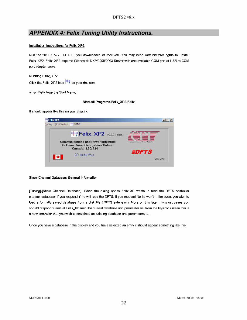
APPENDIX 4: Felix Tuning Utility Instructions. � ����� ��� � ��� ��� � ������� ������ ������� ��������� ��������� ����� ��� � ��� ��� � ������� ������ ������� ��������� ��������� ����� ��� � ��� ��� � ������� ������ ������� ��������� ��������� ����� ��� � ��� ��� � ������� ������ ������� ��������� �������� � �����! "�#�! � �$�%�&����'&(�)+*,�.- (��&(#/��.��0���12��� ����0���0#�.��� �����. 3���0.-�4.�.�#5,��/6�"����087.0.52 �� ���!� ��� �.�&� 9. "� �:� �; �"��� �.� ��%�.� �����&���.-<�%�.� �����&���:� ��=.�� � ����>? �"0���1,�A@B)DC �&��C ��E�E�E�C ��E�E�FG'.�.� 3��.��12 �! +�.�"�G��3��. � �.H�� �GI,JLKNM"�.� �<�.�A*B'&OG� �GI,JLKM"�.� ���0��.M"� �.�%���.H�� �.-
� ��� ��9P����� ��������� ��� ��9P����� ��������� ��� ��9P����� ��������� ��� ��9P����� ��������I2� �AQ.�! "�R�%�.� �����&���R ���.� �.�,/��.���%0����AQS� �.M�T �.�D� ���2�%�.� �&�!� �.5U�! "�2'.� �.� ��K,�.����V '�� ��� �'�� ��� �'�� ��� �'�� ��� � WW WWX7�� �Y��� �9�� ��5+�7�� �Y��� �9�� ��5+�7�� �Y��� �9�� ��5+�7�� �Y��� �9�� ��5+��WW WW%����� ������������� ������������� ������������� ��������BWW WW%����� ��-����� ��-����� ��-����� ��-
� ��A "�.��� 02�.M�M"���.�D� QS�2�! � �&�.�,/��.���%0. �AM�� ��/A-
'� ��1#IG ���������YZD�� ��H������V\[&������� ���Y� ��� ��� 5+��� ���'� ��1#IG ���������YZD�� ��H������V\[&������� ���Y� ��� ��� 5+��� ���'� ��1#IG ���������YZD�� ��H������V\[&������� ���Y� ��� ��� 5+��� ���'� ��1#IG ���������YZD�� ��H������V\[&������� ���Y� ��� ��� 5+��� ��� ] )+���� �"9�^ W ] '& "��1_I2 "�.���"�.�`ZB��� �.H"������^!-,>? "�.�P�! "�a0. �.� ��9a�.M"�.�"�b�%�.� �����&�a1,�.�"� �?� �c� ����06�! "�dZ,�%)D'd���.�"�!� �.� � �.��A "�.���"�.��0���� �.H"�����.-B� �B/��.� � ���AM"�.�"0 4a "�G12 � ��� ����0G�! "�:Z,�%)D'&-<� �</��.�G� ���AM"�.�"0:@B�: "�G1,�.�"e �f �+�! "�G��3��.�"�</��.�+12 �A +� �� ����0U�U� �.� 5,�.� � /R����3���0U0���� �.H"�����U�!� �.5g�U0. �AQ2�! � �ih - Z,�%)D'i����� �.�"�A �.�"j�-,K,�.� �P�.� �! � �?� ��� �.� -$� �P5,�����,���������k/��.��A "�.��� 0:� ���AM"�.�"0G4:�.�"0:� ���f�%�.� �����&�:� ����02�! "�2�A��� � �.�"�0���� �.H"�����2�.�"0RM"�.� �.5,��� �.�%������!� �.5U�! "�RQ�� /����!� �.�2����� �����&�! � �� ��R�"��1U���.�"�!� �.� � �.�%�! "���/��.�,12 �A ,� �20���12��� ����02�.�,���A ���! �"920���� �.H"�����2�.�"0RM"�.� �.5,��� �.� �&� �.-
JL�"���2/��.�2 "��3��2�20���� �.H"�����R �,�! "�20. �AM�� ��/&�.�"02/��.�2 "��3��2���.� ����� ��02�.�,�.�"�!� /� ��A "�.��� 02�.M�M"���.�%���.5,���! � �"9R� QS�2�! � �AV

DFTS2 v8.x
MAN90111400 March 2008: v8.xx
23
\\
• l ��� �0��.��H�� ���A� �AQ W+H�� �"9��&�! "����A ,� �2�! "�2��0. ����.� � �
•� 9. "��A� �AQ WD�A "��1i5,�.���,� �.�%�.� �S�!���"���! �.�"�
•(.�"� �.� WD�!���"���&� �2�! "�2���.� ����� ��02�A "�.���"�.�
•� �"���.� � W+M"�.M"����M,�! "�R��������1,�.� 0R� ��M��"��M�� �.52M"�!-
•K W+5,�.5,�.� m����&�! "�2�A "�.���"�.�
•I WDI2� ���.�%�! � �&�A "�.���"�.��h �.� �S0���� �2E�E�E�E�E���j
•� W l ����0�C
� ����02�20���� �.H"�����2�! � �2�!� �.5U0. �AQ•' WD'.��3���C >?� � �2�! � �&0���� �.H"�����2� �2�20. �AQ.�! � �.-
>? "�.�,�! "�R ��M��"�� ���A�"�� �&�.�,�. �! "�.�D� ����H"���&�.�D �,�.�"/&��0. ����.� �S�! "�2� �.� � ��12 �"9RQS��/����!� �.QS���&�.� �2n\ "��� n\-
•�Do"W��%p WD���.� ����� �&I,��3A � /�o,WDpR� ���AM"�����! 3��.� /
h �%pR �� 9.�"�.� ��0212 "�.�2�"�A �"92�2q2����3A � /&���.�"�!� �.� � �.� j
•�%r WD���.� ����� �&�! "�2��� �.M,�A m��2��0. ����.� � -
�.�D�"���2�! "�R� 9. "��5,�.�"���RH��"� � �.�,� �RH�� �"9R��M,�R5,�.���,�.�,�.�"/&�A "�.���"�.�S�.�"�!� /A- )+ "�R(.�"� �.�DQS��/&12 � �� 525,��0. ��� �.� /&�!���"�2�! "�RQ�� /����!� �.�,� �2�! "�2���.� ����� ��02�A "�.���"�.�� �,�! "�2I2 "�.���"�.��ZB��� �.H"�����R� ���!- )s�� ��9 �� ��PQ�� /������ ���s1G �� s�� ��PQ!�/�H����� 0)s�� ��9 �� ��PQ�� /������ ���s1G �� s�� ��PQ!�/�H����� 0)s�� ��9 �� ��PQ�� /������ ���s1G �� s�� ��PQ!�/�H����� 0)s�� ��9 �� ��PQ�� /������ ���s1G �� s�� ��PQ!�/�H����� 04.�.�,���.�,9. 3��2�! "�2� ���A�"�&� �2�.�"/&����! "�2����3A � /&��0. ����.� � �� �,�! "�2� �.� � ��12 �"921,��/AV
•�Do,W+�%piWD���.� ����� �&����3A � /�o,WDpR� ���AM"�����! 3��.� /�h �A �&����3A � /&���.�"�!� �.� � �.� ��j�t
•�Do,W+�%qiWD���.� ����� �&����3A � /�o,WDqR� ���AM"�����! 3��.� /�h �! 3��2����3A � /&���.�"�!� �.� � �.� ��j�t
•�%r2WD���.� ����� �&�! "�2��� �.M,�A m��2��0. ����.� �
•H"/&�A� �AQ� �"92�.�,�.�,��0. ����.� �S�.�D�"�A �"92�! "�2)D7&O2�.�%'&u,� �%)DW )D7&ORQS��/&� �R5,��3��2�! "�2� ���A�"�&� �2�.�,��0. ����.� � t
@B��1_�"���P�! "�a��M"C 0���12� �.� � ��1_QS��/��k� �P�!���"�P�! "���,����3A � /A-,uB�.� �a �k�P�A�"9�9������ ��0a5,���! "��0P� �.���!���� �"9P���v=.�� �AQ�� /v���M"�����A H�� �R�"�A �"92�.��� /&�! "�RQS��/AH"���.� 0.V

DFTS2 v8.x
MAN90111400 March 2008: v8.xx
24
•n\M"�.M"n�� �2�! "�2����3A � /&/��.�,1,�.�"�12 �! ,�.�2�Do"W��%q2�.�D�%p2�!���"���! �.�2QS��/
•�"��1i�"���2�! "�R*,�2�.�DZBJ`>?@w�.� � ��1iQS��/��&� �R5,��3��2�! "�2����3A � /�H"/&�! "�R �"�A� �.5,�.�"��A "��12�2 �,�! "�2'.� �.M,'& m��2���.� �
•M�� �������%r2����.�"/��! 5,�2� �R5,��3��2� �2�! "�2��� �.M,�A m��2���.� �
4.�.�w���.�U�"���U�! � �x5,���! "��0U� �U=.�� �AQ�� /x5,��3��U�!� �.5g����3A � /R� �U����3A � /R�.�"0U�!���"�U�! "�U0���3A ���.- � �.5,�.52H"�.� TB)D7&OP�.�"0'&u,� �%)DW )D7&O212 � ��5,��3��2/��.�,� �.� 1,�.� 02�.�DH"���AQS1,�.� 02�! �� �.�"9. ,�! "�2��0. ����.� � ��� ���AM"�����! 3��.� /A- � �A�! "�L� �.� 9����A����3A � /:M"���A �! �.�Lh I2��� � �.�"�sM"���A �! �.�zy�CDW{'.� �.Mz�A m���j{12 � �"����������0w�! "�U�����A �! �.� l 52 �+M"�.� �.5,��� �.�Y�.�Y12 � ��H"�� �����&�! "�.�,E.T��! "�2����3A � /&1,�.�"e ��5,��3��.- IG �����9� ��9 I+�3� � /�'�� ��Ms'� m��IG �����9� ��9 I+�3� � /�'�� ��Ms'� m��IG �����9� ��9 I+�3� � /�'�� ��Ms'� m��IG �����9� ��9 I+�3� � /�'�� ��Ms'� m���.� �������%r2�.�"/��! 5,�2�! "�2� ���A�"�� �&�.�,�.�"/&��0. ����.� �S�.�%�. �! "�.�%����! "�R� ����H"�������A- I2 "�.�"9��|�! "�|��� �.M}�A m��~H"/��"�A �"9��! "�����A� �.� ��H"�.�c�.�c�! "��QS��/AH"���.� 0.-b)+ "����� �.M��A m���5,��3����� �o�T �.T q.T o"E.T ��E.T q�E.T o"E�E.T ��E�E.T q�E�E.T o"E�E�E.T ��E�E�E.T q�E�E�E6 �"�A� �.5,�.�"�f����� �! �"9��A-f*B���:�! "�6*,�R�.�"0xZBJ`>?@iQS��/���� �R�A "�.�"9��R�! "���� �.M �A m��.-,(�3��.� /��! 5,�P/��.� �A "�.�"9��a �!TB�! "�a�"��1$��� �.MG�A m��6 �v�.�"� �.5,���! ���.� � /v���.�"�f� �:�! "�6Z,�%)D'&Tf�"�6�"����0:� �6M�� �����(.@B)+( � �.�,�! "�2���.� �S� �2������! "�2��� �.M,�A m�� � �D/��.�z12 �A z� �U�"���w�w��� �.Mz�A m��w���! "�.�Y�! "�.�z�! "�����w�.�"� �.5,���! ���.� � /2���.� ����� ��0.T%�.�"� �.�Y�! "�w3��.� �"�U �z�! "�w��� �.Ms�A m�� ��0. �B���.� ��.�"0RM�� ������(.�"� �.�%� �2������! "������ �.M,�A m��.- '��� �� ��9 �P�A� �=���������/k���� ��9P ��� ��� M���� ��� ���'��� �� ��9 �P�A� �=���������/k���� ��9P ��� ��� M���� ��� ���'��� �� ��9 �P�A� �=���������/k���� ��9P ��� ��� M���� ��� ���'��� �� ��9 �P�A� �=���������/k���� ��9P ��� ��� M���� ��� ���@BJ`)+(.V+)+ � �bM�� ������0.��� �a�����A��5,���?�! "���2���.� � �����R� �"� �.� M"�.� ���! �.�PI,����� �! �A �.�"� �AT,�.�"0a�! "� l �"���.�w� �"� �.� M"�.� ���! �.� l 52 �M"�.� �.5,��� �.�D "��3��RH"���.�2 �� �! �.� ����0R �,�! "�RZ,�%)D'R���.�"�!� �.� � �.� (.�"� �.�s�d�D� ��=.�"�.�"��/g �:�! "�d�D� ��=d(�0. �����.� ���.�"0dM�� �����g(.@B)+( � -f)+ "�dZ,�%)D'd12 � �A��� � �.52M"��� �� �"� �.� M"�.� ��� �x� �x�! "��!� ��=.�"�.�"��/ �.�"0��������! "������3A �! ���A-�� ���! "���!� ��=.�"�.�"��/P � �.�"� �A 0����! "�#M"�.� 52 � � ��0#K2 �"C!K,��� �!� ��=.�"�.�"��/PM"�.� �.5,��� �.�3��.� �"����.�,�.� � �.�%12 � ��H"�R� �.M"�.� � ��0.- 7.� � �.�z�A�"�����������!���` �"� �.� M"�.� ���! �.��T2�%�.� �����&�a12 � �`��M"0���� �a�! "�a��0. �2���.� � �?12 �! ��! "�d�"��1�����3A � /gM"���A �! �.�"���.�"06�! "� �"� �.� M"�.� ��� ��02�!� ��=.�"�.�"��/&�.�"02�A "��1U���&�A "�.���"�.�SE�E.- *B����9��8)+ M�-D4.�.�w���.�U�"��1g�����+�! "�U�A "�.���"�.�.����52H"�.�` �w�! "�UI2 w��0. �+���.� ��� �U�.�U�����"����0U�A "�.���"�.���.�"0U���.� �����+�! "�] K,�.5,�.� m��2I2 "�.���"�.� ^�H��"� � �.�,� �2����3��2�! � �&�!� ��=.�"�.�"��/&�.�"02����3A � /&0���� �2� �2�! "�����"��1U�A "�.���"�.������52H"�.� )s ��PO���� � ������V)s ��PO���� � ������V)s ��PO���� � ������V)s ��PO���� � ������V K+��5+��� m��K+��5+��� m��K+��5+��� m��K+��5+��� m���V�12 � �<� �.QS�#�! "�#0���� �$ ���! "�#��0. �z���.� � �AT��A "���AQP �z��/A�"� �����! ���.� � /P�.�"0$ �z���.� � �����!TA�����s�! "�NQ�� /����!� �.�L� �8�! "����A "�.���"�.���.�"0L�! "�.�LM�� �.52M"�s �A/��.�`12 �A `� �w����3��U �+�"�A �"9w�! "�UK����.525,�.�"0w� �w�! "�UZ,�%)D'&-�I2 "�.���"�.������52H"�.�{52�"���+H"��!� �.5io"W q�E.- '��3��PZ+��)A'P�'��3��PZ+��)A'P�'��3��PZ+��)A'P�'��3��PZ+��)A'P�G12 � �S����3��2�! "�20���� �.H"�����2�.�"02�.� �S�A��� � �.�"��M"�.� �.5,��� �.� �� �,�R- Z,�%)D'R�! � �.-
l ��0#Z+��)A'#�l ��0#Z+��)A'#�l ��0#Z+��)A'#�l ��0#Z+��)A'#��V%12 � �Y� ����0 �! "� 0���� �.H"����� �.�"0 �.� ���A��� � �.�"�,M"�.� �.5,��� �.� �k �s�P- Z,�%)D'P�! � �.-\)+ "� 0���� �.H"�����P �kM�� ������0P �s�! "��A "�.���"�.�:� ���#�.�"0��.� �G�A "�.���"�.� ��12 � �:H"��5,�.� QS��0�12 �! b��M�� ������0. �"9�n\5,nc �"0. �����! �"9��! "��/� "��3����"���NH"���.�����3���0�C!5,�.5,�.� m���0R �,�! "�RZ,�%)D' � ��0:��� ��0�� �:��� ��5N�� ��6Z+��)A'6�� ��0:��� ��0�� �:��� ��5N�� ��6Z+��)A'6�� ��0:��� ��0�� �:��� ��5N�� ��6Z+��)A'6�� ��0:��� ��0�� �:��� ��5N�� ��6Z+��)A'6��V�12 � �D� ��W�� ����0k�! "�?Z,�%)D'?���.�"�!� �.� � �.�B0���� �.H"�����k�.�"0?��M"0���� �k�! "�v0���� �.H"�����v0. �AM�� ��/12 �! ,�! "�R�"��1i �"� �.-+)+ "�R����52H"�.�%����A "�.���"�.� ��� ����0R �&0���� �.� 52 �"��0RH"/&�! "�2����� �! �"92����! "�2I2 "�.���"�.� �&��0. ����.� � -

DFTS2 v8.x
MAN90111400 March 2008: v8.xx
25
� ��0?I+�3� �� ��� ��0?I+�3� �� ��� ��0?I+�3� �� ��� ��0?I+�3� �� ���V�12 � �f� ����0#�! "�$Z,�%)D'$����3A � /aM"���A �! �.�"�P�.�"0$M�� �����#�! "�$� ���A��� � �a ���! "�#��0. �z���.� � �P���PI2 "�.���"�.�<E�E.-�D� ��=.�"�.�"��/� �"� �.� 5,���! �.�2 �����"0����! �"��0R �,�! � �&�������.- '� ��1$K+����'� ��1$K+����'� ��1$K+����'� ��1$K+����VM"�.M"����M,�! "�2���.5,�R5,�.���,/��.�,�����212 "�.�,/��.�2� 9. "��5,�.�"���RH��"� � �.�,�.�,�! "�2I2 "�.���"�.��ZB��� �.H"����� l ���!H"���A- uD��5+�U���� �� ���uD��5+�U���� �� ���uD��5+�U���� �� ���uD��5+�U���� �� ���VGK,��3����&�.� �S�! "�2����3A �! ���&� �2�! "�R "�.5,�RM"���A �! �.�2h E�E�E�E�E�j�-�%�.� �����&�212 � ����M"0���� �2�! "�2��0. ����.� � �&12 �! ,�! "��"��1U����3A � /� �"� �.� 5,���! �.�,�.�"02�����I2 ,E�E.-�D� ��=.�"�.�"��/� �"� �.� 5,���! �.�2 �����"0����! �"��0R �,�! � �&�������.- uD��� MuD��� MuD��� MuD��� MV�>? � �S�.M"�.�,�! � �&0����A��5,�.�"� I+��� ��I+��� �� �� ����� ��VI+��� ��I+��� �� �� ����� ��VI+��� ��I+��� �� �� ����� ��VI+��� ��I+��� �� �� ����� ��V4.�.�v52�"���{�! � ���{�!���"�v�! �� ���v�A "�.���"�.� �ATY�! "��H"��� � �.56���{�! "�v�!� ��=.�"�.�"��/UH"�.�"0.TY�! "�v� �.M��.�"0����.5,��12 "�.� �# �&�! "�#52 0�0.� �.T�! "�v�A� �����.�<� �v�! "��52 0�0.� �v�! "��H"��� � �.� -{u, 9. �� 9. "�{�! "�����v�! �� ���v�A "�.���"�.� �U ���! "���A "�.���"�.�<� ���!H"��� �.�"0��A� �AQs�! "�#H��"� � �.��-�%�.� �����&����12 � �����.� �A��� ��� ���! "��������� �! �A �.�"� � �.�"0�0. �AM�� ��/G�! "�.52-�7.�A�! � �:M"�. �"�A�! "�L���.� �A��� ��� ��0L������� �! �A �.�"� �:uB7.�&(8@BJ`)H"���.�812� � � �.�8� �N�! "�N���.�"�!� �.� � �.� -sI2� �AQ:�! "�N>?� � �NI,����� �! �A �.�"� �dH��"� � �.�8� ����M"0���� �i�! "�i���.�"�!� �.� � �.�`12 �! U�! "���"��1������� �! �A �.�"� �A-\JL�"��� �! "� ������� �! �A �.�"� ���.� �G12� � � �.�+� �G�! "�G���.�"�!� �.� � �.��/��.�+�A "�.��� 0:�"��1NH"�G�.H�� �G� �: �"� �.� M"�.� ��� �G� �G�.�"/��!� ��=12 �! � �,�! "�RH"�.�"020����! �"��0RH"/&�! "�R5,���&�.�"0R52 �,�!� ��=RM"�.� �.5,��� �.� �A- )+ "�P� �"� �.� M"�.� ���! �.�sI,����� �! �A �.�"� ��0. �.� ��9 �.� ��� �A��M�M"�.� � �����.�"0. �"9G�A �"9.� �G������� �! �A �.�"� ��� �G�! "�G���.�"�!� �.� � �.� -��A�"���f�"��3A 9���� �G� ��! "�:������� �! �A �.�"�f/��.�G12 �A G� �:���.�"0:�.�"06M�� ������(.�"� �.�A�.�G�! "���f��0. �f���.� � -<)+ "���f�A �"9.� �:������� �! �A �.�"�f12 � ��H"�R���.�"��� �R�! "�Z,�%)D'R�2���.�"�!� �.� � �.� -
Z,�%)D'g���.�"0g�%�.� �����&���g5,�. �"� �. �v� 1,���A "�.���"�.�B0���� �.H"�������U�A��M�M"�.� � ��0gH"/P� 1,�#0. ���! �"���w �"� �.� M"�.� ���! �.��������� �! �A �.�"�� �.H�� ���A-{>? "�.�v���.� �A��� ���! �"9��.�"0$5,�.�� M���� ���! �"9$ �"� �.� M"�.� ���! �.��������� �! �A �.�"� �AT��! "�#�����! 3��#0���� �.H"�����#0���� �.� 52 �"���P12 � �A � �.H�� �2���������� �! �A �.�"� �� �� �2�"���.- �A� �=���������/k� ��� ��� M���� ��� ����A� �=���������/k� ��� ��� M���� ��� ����A� �=���������/k� ��� ��� M���� ��� ����A� �=���������/k� ��� ��� M���� ��� ����&����R� ��R� �� �� ���� �� � ��R����� � � ��� ��� ���� �R���� ���� �� ��R���R�+� � � � ��R� �R� ��R����� � �� � �� �¡ ����R¢+�� �L¢+��� � � ��� ��� �L�£��¤!��¥,¦���k����k��� ��,��&����R� ��R� �� �� ���� �� � ��R����� � � ��� ��� ���� �R���� ���� �� ��R���R�+� � � � ��R� �R� ��R����� � �� � �� �¡ ����R¢+�� �L¢+��� � � ��� ��� �L�£��¤!��¥,¦���k����k��� ��,��&����R� ��R� �� �� ���� �� � ��R����� � � ��� ��� ���� �R���� ���� �� ��R���R�+� � � � ��R� �R� ��R����� � �� � �� �¡ ����R¢+�� �L¢+��� � � ��� ��� �L�£��¤!��¥,¦���k����k��� ��,��&����R� ��R� �� �� ���� �� � ��R����� � � ��� ��� ���� �R���� ���� �� ��R���R�+� � � � ��R� �R� ��R����� � �� � �� �¡ ����R¢+�� �L¢+��� � � ��� ��� �L�£��¤!��¥,¦���k����k��� ��,�� � �§����!¦� �� �R¨G©Dª� �� �R� ��R«A¬+�®b��� ������ �A���2��� �������� ��+� �R¯G��¤!�R� ��R����¤!� � � ���� �R� ����� � �§����!¦�°x± ���� � �§����!¦� �� �R¨G©Dª� �� �R� ��R«A¬+�®b��� ������ �A���2��� �������� ��+� �R¯G��¤!�R� ��R����¤!� � � ���� �R� ����� � �§����!¦�°x± ���� � �§����!¦� �� �R¨G©Dª� �� �R� ��R«A¬+�®b��� ������ �A���2��� �������� ��+� �R¯G��¤!�R� ��R����¤!� � � ���� �R� ����� � �§����!¦�°x± ���� � �§����!¦� �� �R¨G©Dª� �� �R� ��R«A¬+�®b��� ������ �A���2��� �������� ��+� �R¯G��¤!�R� ��R����¤!� � � ���� �R� ����� � �§����!¦�°x± ��� ��R� � �§R��� �� ��k�� � ����¦��R� � �§R��� �� ��k�� � ����¦��R� � �§R��� �� ��k�� � ����¦��R� � �§R��� �� ��k�� � ����¦��²�� ��� �w� �v� ��v��� �£����� `� ��v����� � �� � ��f¯G��¤!��w� �v� ���{�������� °{± �{� ��v� � �§����!¦U� � �+� � �� ��� ���� ���³���� ���� � ������ �� �� ���� �� � ��� z�� ������²�� ��� �w� �v� ��v��� �£����� `� ��v����� � �� � ��f¯G��¤!��w� �v� ���{�������� °{± �{� ��v� � �§����!¦U� � �+� � �� ��� ���� ���³���� ���� � ������ �� �� ���� �� � ��� z�� ������²�� ��� �w� �v� ��v��� �£����� `� ��v����� � �� � ��f¯G��¤!��w� �v� ���{�������� °{± �{� ��v� � �§����!¦U� � �+� � �� ��� ���� ���³���� ���� � ������ �� �� ���� �� � ��� z�� ������²�� ��� �w� �v� ��v��� �£����� `� ��v����� � �� � ��f¯G��¤!��w� �v� ���{�������� °{± �{� ��v� � �§����!¦U� � �+� � �� ��� ���� ���³���� ���� � ������ �� �� ���� �� � ��� z�� ����£�¦ ���� �¯G� ��²�²�²�²�²� z� � ������ ����� ���³���� �������� � �� � �������� ´� ������ �� �� ���� �� � ��°�± �A� ��L� � �§����!¦:� �G�£�¦ ���� �¯G� ��²�²�²�²�²� z� � ������ ����� ���³���� �������� � �� � �������� ´� ������ �� �� ���� �� � ��°�± �A� ��L� � �§����!¦:� �G�£�¦ ���� �¯G� ��²�²�²�²�²� z� � ������ ����� ���³���� �������� � �� � �������� ´� ������ �� �� ���� �� � ��°�± �A� ��L� � �§����!¦:� �G�£�¦ ���� �¯G� ��²�²�²�²�²� z� � ������ ����� ���³���� �������� � �� � �������� ´� ������ �� �� ���� �� � ��°�± �A� ��L� � �§����!¦:� �G�B�� ��� ��L� ��L� � ����.� �� �� ���� �� � ���� ��� ��L� ��L� � ����.� �� �� ���� �� � ���� ��� ��L� ��L� � ����.� �� �� ���� �� � ���� ��� ��L� ��L� � ����.� �� �� ���� �� � ��� ���³��� ,� �� ����� � �� � ���������µ��� �£�� � ��± �� �� ���� �� � ��°� ���³��� ,� �� ����� � �� � ���������µ��� �£�� � ��± �� �� ���� �� � ��°� ���³��� ,� �� ����� � �� � ���������µ��� �£�� � ��± �� �� ���� �� � ��°� ���³��� ,� �� ����� � �� � ���������µ��� �£�� � ��± �� �� ���� �� � ��° � 9� ��,5+�������PH��� � ��� 5+����V� 9� ��,5+�������PH��� � ��� 5+����V� 9� ��,5+�������PH��� � ��� 5+����V� 9� ��,5+�������PH��� � ��� 5+����V� ��/��.�R� 9. "��5,�.�"���xH��"� � �.�2WGh � K2O�j+�.�"/�12 "�.� �R�.�2�! "�RI2 "�.���"�.��0���� �.H"�����x� ���!T/��.��9����.�k���.�"� �����&5,�.����12 �! ��! "�� �.� � ��12 �"92���.� �����! �.�"�A-
•] I2 "�.�"9��G� �G�! � ���A "�.���"�.� ^!V�)+���"����� �G�! "�G���.� ����� ��0G�A "�.���"�.� -<� �<1,�.� QS���.�,12 "��� ��3��.�%0���� �.H"�����2�.�"�!� /� �&���.� ����� ��0h l K2O�j�T�12 � �A 25,��/&�.�D5,��/��"����H"�2�! "�2�.�"�!� /&/��.�,1,�.� �2�.�,12 "�.�,/��.�,0. 02�! "�
� K2O•] � ����02�! � �&�A "�.���"�.� ^!V�12 � ��� ����02�! "�2���.� ����� ��02�A "�.���"�.�S�.�"0RM�� �����2�! "�20���� �R �,�! "�2����3A � /&��0. ����.� � �
•] I2� ���.�B�! � �L�A "�.���"�.� ^!Vk12 � �%�A� ���.�B�.� �%�! "�k0���� �? ���! "�k�A "�.���"�.� T������ �! �"9?�D� ��=k�.�"0v�.� �\����3A �! ���w� �vE�E�E�E�E� ���! "����.�"�!� �.� � �.� -•
•] )+���"�2����3A �! ����^!V+���.� ����� �&����3A � /�o,�.� � ��12 �"92/��.�,� �R5,�.���"�.� � /&�!���"�2�! "�2����3A �! ���&12 �! ,�! "�R��M"C 0���12�,�.� � ��1iQS��/��A-
•
•] '.��3��2�.�"0 � ����020���� �.H"������^!V+1,�.� Q.�! "�2���.5,�2���&�! "�2'.��3��2�.�"0 � ����0RH��"� � �.�"�
•] � ����02�! � �&�A "�.���"�.� ^!V�12 � ��� ����02�! "�2���.� ����� ��02�A "�.���"�.�S�.�"0RM�� �����2�! "�20���� �R �,�! "�2����3A � /&��0. ����.� � �A-
•] I2� ���.�%�! "�20���� �.H"������^!V+12 � �S�A� ���.�%�! "�2�.�"�! � �2�A "�.���"�.�S0���� �.H"�����.-
•
•] Z,�%)D'x��������1,�.� 0�^!V+�.�"� �.�%�! "�RZ,�%)D'R������������M"������1,�.� 0.-

DFTS2 v8.x
MAN90111400 March 2008: v8.xx
26
•] Z,�%)D'R�2I,�.�"�! 9.��� ���! �.�"^!V+0. �AM�� ��/&�! "�R� l 7.'&uw���.�"�! 9.��� ���! �.�,0. �.� ��9
•] � �"� �.� M"�.� ���! �.�,I,����� �! �A �.�"� ��^!V+0. �AM�� ��/&�! "�2������� �! �A �.�"� �&0. �.� ��9.-
•] I,�.�"�!� �.� � �.� C!���.� ���.�"�.� � /�K,��0.��� ��^!V¶0. �AM�� ��/a�! "�$7.0�3��.�"����0$I,�.�"�! 9.��� ���! �.�#0. �.� ��9.-w@B��� �$�! "���
“M"�.� ���.�"�.� � /
5,��0.��� �” "�����"�R5,���.�� �"9R �2Z,�%)D'.�.V �� �&�2� �.� 5U�! "����� �.� ��� ���&� �2�! "�R �� �! �.�S3��.� �A �.�2Z,�%)D'&-
•] � �"� �.� �����! 3��2)+���� �"9�^!V+0. �AM�� ��/&�! "�2� �.� 52 �"�.�� �"� �.� � �����20. �.� ��9.-
•] )+���"�.�%I,/��A� �"9�^!V+0. �AM�� ��/&�! "�2��/��A� �"920. �.� ��9.-
���� ��5+�� ����I+������� ������� ��5+�� ����I+������� ������� ��5+�� ����I+������� ������� ��5+�� ����I+������� ���ZB�.��H�� �L�A� �AQ+�.�`�.�"/:M"�.� �.5,��� �.�. �`�! "�LI,�.�"�!� �.� � �.�.���.� �.5,��� �.� �:� ���A� �L�.M"�.�`�.�`��0. �A���.� ���! "���A12 � �M"�.� 52 �A/��.�z� �w������! "�?�A��� � �.�"�&3��.� �"�?� �.�f�! "���LM"�.� �.5,��� �.��h ���U· �"���L� ����0��!� �.5d�! "�gZ,�%)D'.j�T{�.�"0��! "���A��� � �.�"�LK2 �v�.�"0gK,���U� �.�f�! � �M"�.� �.5,��� �.� TD �D�.M�M�� ���.H�� �.-%4.�.�z���.�s�.�"� �.���P�"��1#3��.� �"� �.�"0PM�� �����k(.@B)+( � �.���A� �AQ ] JL¸�^B� � ���.�"0 �! "���,M"�.� �.5,��� �.�2� ��! "�RZ,�%)D'&-G¸.� �AQ ] I,�.�"���.� ^� �RH"���AQ.�.�"��.�"0R� ����3��2�! "�RM"�.� �.5,��� �.�D���"�A "�.�"9���0.- ���.� �.5,��� �.� �&�.� �RM"������1,�.� 0RM�� ��� ����� ��0.-*B���2�! "� ] Z,�%)D'x��������1,�.� 0�^�5,�.���,���.� �����! �.�,� �29��. �,�����������A- 4.�.�s���.�s�.� ��� · �"���,� 9. "�B�A� �AQf�! "�P5,�.�"��� � � 0. �AM�� ��/��! "� �A��� � �.�"�B3��.� �"� ���B�! "� ���.� ����� ��0P � �.5$ �s�! "�P���.� �.5,��� �.��� ���B����! "�RH"��� � �.5U����! "�20. �.� ��9.- )+ "� ] � ����0����.� �.5,��� �.� ��^`H��"� � �.��12 � �<� ����0��.� ���! "�����.�"�!� �.� � �.��M"�.� �.5,��� �.� �P �"� �#5,�.5,�.� / �.�"0��A "�.��� 0#H"��0��.�"�#H"��� �.� �/��.�,����3��2�20���� �.H"�����2�! � �2� �2�.�"�A��� �2�! "����! "�2�A��� � �.�"��Z,�%)D'R���.�"�!� �.� � �.�DM"�.� �.5,��� �.�%������ �&����3���0R �,�! "�R- I2�.���! � �.-
Z+��)A'�� I+������� ��� � ����I+������ 9��� ��� ���Z+��)A'�� I+������� ��� � ����I+������ 9��� ��� ���Z+��)A'�� I+������� ��� � ����I+������ 9��� ��� ���Z+��)A'�� I+������� ��� � ����I+������ 9��� ��� ���

DFTS2 v8.x
MAN90111400 March 2008: v8.xx
27
7.������������0aH"/v�A� �AQ� �"9:�! "� ] 7.����������K,�.���"^�H��"� � �.�_�!� �.5N�! "�:I2 "�.���"�.��ZB��� �.H"�����:0. �.� ��9.T<�.�"0:���.� �����! �"9 ] Z,�%)D'6�I,�.�"�! 9.��� ���! �.�"^�.�%�!� �.5U�! "�R5,�. �25,�.���2H"/&���.� �����! �.� ] )+���� �"9�^ W ] Z,�%)D'R�2I,�.�"�! 9.��� ���! �.�"^!-
)+ � �v0. �AM�� ��/v�A "��1,�v�.� ���! "�:���.�"�!� �.� � �.�sM"�.� �.5,��� �.� ��h �! "�6�"���f�! "�x �"� �.� M"�.� ���! �.�2������� �! �A �.�"� ��j+�����R9.� �.�"���.-4.�.�2���.��"��3A 9���� �v� �v�.�"/w��0. �{���.� �\�.�"0v�.�"� �.�<���"��163��.� �"�v� �.�<�! "��M"�.� �.5,��� �.�<�.�"0v�! "�.�vM�� �����U(.@B)+( � � �����.�"0��! "�����A �"9.� �M"�.� �.5,��� �.�%� �2�! "�2���.�"�!� �.� � �.� -
� ��� ��� ����� 3�� )s�� ��9PZ+ ���� ��� ��� ����� 3�� )s�� ��9PZ+ ���� ��� ��� ����� 3�� )s�� ��9PZ+ ���� ��� ��� ����� 3�� )s�� ��9PZ+ ��� �9�9�9�9
)+ "�#� �"� �.� �����! 3���)+���� �"9#Z, �.� ��9# � ��������������0��!� �.5 ] )+���� �"9�^ W ] � �"� �.� �����! 3���)+���� �"9�^z5,�. ��5,�.���&���.� �����! �.�&�.��!� �.5x�! "�] � �"� �.� �����! 3��2)+���� �"9�^�!� �.5U�! "�2I2 "�.���"�.��ZB��� �.H"�����R5,�.����- )+ "��� �"� �.� �����! 3��v)+���� �"9v12 �"0���1d �w�������.�"�! �.� � /w�v�A5,�.� �{� �.� 52 �"�.�B �"� �.� � �����v� ���! "�#Z,�%)D'&-�4.�.�&���.�&�.�"� �.��.�"/ 3��.� 0���.525,�.�"0P �s�! "� ��0. �B���.� ���.�"0PM�� �����k(.�"� �.��� �G���.�"0G�! "���<���.525,�.�"0G� �G�! "�G�!���"�.� -<� �<�! "�G�! � �:u,( l �����&�.- �.Z,�� �v �+�! "�� ���"�! 5,�20. � ����� �.� /AT��! "�R "�.� M2H��"� � �.�,12 � �S�.M"�.�2 �!-�)+ � �� �&�R5,�.���"�.�S� �.�%�! "�2�A��� � �.�"��Z,�%)D'R�R�D� ���A ,3��.� �A �.��-
)+ "� ] '.��3��P� ��9 � � 0. �AQS^,H��"� � �.�s12 � ������3�� �! "� �A��� � �.�"�B���.525,�.�"0P� ��9P � ��� �.� /k �"� � � � �����B�! � � �.�s0. �AQ�-\)+ "����� �! � ���v5,��/M�� ��3��R "�.� M"�!���� �,�!� �.��H�� �2�A "�����! �"9.- I,�.525,�.�"0��w���.�"�{� �v�! "��Z,�%)D'�12 � �BH"�v0. �AM�� ��/���0� ���! "�v)+���� �"9 l ��9�� ���!H"���AT{M�� ������0���0�H"/w�! "���! 5,������0���/ ��� �.52M�.�"02)D�&V � �"� �.� 5,���! �.�R� �����. 3���0R�!� �.5i�! "�xZ,�%)D'x12 � �AH"�R0. �AM�� ��/���0x ���! "�k)+���� �"9 l ��9?� ���!H"���8M�� ������0���0?H"/L�! "�k�! 5,�k���.0���/��� �.52M,�.�"0 � �R���&�A "��12�2H"�.� ��12V ] o"E.V q�r.V F�q�^�V�)D�&W ¹ > º<W W W WD���.525,�.�"02���.�"�� �2�! "�RZ,�%)D'] o"E.V q�r.V F�p�^�V � �&W ¹ I2�.� W ».- ¼�¼i4vº<W W W W+� ���AM"�.�"���R� �����. 3���02�!� �.5U�! "�RZ,�%)D'R�Rh �2Z,�%)D'R���.52M"���! H� � � /�5,��0���j

DFTS2 v8.x
MAN90111400 March 2008: v8.xx
28
•@DJ&)s(�V8O�v����� �����\1G �� ��� �w0� ��� �9�-Y4����&�����&��������� ����0#5+�0� � / 7 ll Z+��)A'#�#M���� ��5+�� ��� � �� � ����9� &�� ��@DJ&)s(�V8O�v����� �����\1G �� ��� �w0� ��� �9�-Y4����&�����&��������� ����0#5+�0� � / 7 ll Z+��)A'#�#M���� ��5+�� ��� � �� � ����9� &�� ��@DJ&)s(�V8O�v����� �����\1G �� ��� �w0� ��� �9�-Y4����&�����&��������� ����0#5+�0� � / 7 ll Z+��)A'#�#M���� ��5+�� ��� � �� � ����9� &�� ��@DJ&)s(�V8O�v����� �����\1G �� ��� �w0� ��� �9�-Y4����&�����&��������� ����0#5+�0� � / 7 ll Z+��)A'#�#M���� ��5+�� ��� � �� � ����9� &�� ������� ��B�� ��P� ��� ��� ����� 3�� )s�� ��9P� ��� ��� � �����-B@DJ6IGu+(IG¸'P��� �P5+�0� � ����3���� 0PM���� ��5+�� ����3���� �����-����� ��B�� ��P� ��� ��� ����� 3�� )s�� ��9P� ��� ��� � �����-B@DJ6IGu+(IG¸'P��� �P5+�0� � ����3���� 0PM���� ��5+�� ����3���� �����-����� ��B�� ��P� ��� ��� ����� 3�� )s�� ��9P� ��� ��� � �����-B@DJ6IGu+(IG¸'P��� �P5+�0� � ����3���� 0PM���� ��5+�� ����3���� �����-����� ��B�� ��P� ��� ��� ����� 3�� )s�� ��9P� ��� ��� � �����-B@DJ6IGu+(IG¸'P��� �P5+�0� � ����3���� 0PM���� ��5+�� ����3���� �����-
� 9� ��,K+�������PO���� � ���� 9� ��,K+�������PO���� � ���� 9� ��,K+�������PO���� � ���� 9� ��,K+�������PO���� � ���� �</��.�+�A� �AQ��! "�:� 9. "�f5,�.�"���:H��"� � �.�+�.�"/�12 "�.� �: �+�! "�G�!���� �"9:� ��9:� ���!H"���AT<�%�.� �����&�:M�� ��0.�"�������G�A5,�.� ��5,�.���,�! "����� ��� �/��.������3��v�! "��� ��9v� ��0. �AQ h ���.5,����� �A� �AQ� �"9��! "� ] '.��3�� l ��9�� �#�D � ��^zH��"� � �.�"j��.����.M"/ �! "�# � 9. �� 9. "� ��0����.525,�.�"0# ��! "�#� ��9�� ���! "���.�"�!� / ���.� � -�)+ � �PM"�.� 52 � � /��.�&� �L� �.QS�L�8M�� ��3A �.�"�G���.525,�.�"0L�.�"08� ��W ���.�"08 �A�����A � /G�.�.M"�.� 52 � �G/��.�`� ���0. ��RM�� ��3A �.�"�&���.525,�.�"02�A� 9. "�!� /&� �R� ��W ���.�"0R �12 �! "�.�"�� "��3A �"92� �R� ��W � /AM"�2�R� �.�"92�A� /AM"�! �&���.525,�.�"0.- )+ "�½5,�.�����.� ���½M�� ��3A 0����i�����������i� �g���.5,�½H"���A �a>? �"0���1,�c�"�! � �! ���c� QS�_@B��� �.M"��0.TzI,�.� �A��� ��� �.����� �a� �.��/��.������.�"3��.�� �.�"���.- ZB�.��H�� �vI2� �AQ� �"9v�.���.���.�"�!� /U ���! "�v)+���"�.� l ��9v12 � �B 525,��0. ��� �.� /w���.M"/U ��� ���! "����0. �����.� � T�H��"�z�"�������.�"0# �!T��! "�.� �.H"/�.� � ��12 �"9P/��.�G� �:��0. �f�! "�:���.525,�.�"0:�! � ���� ���"�����������.� /A-U)+ � �v���.�G����3��:�! 5,�.-f�%�.�A�����.52M�� �.V<�! "�6� ���A��� �f�!� �.5N� ����.525,�.�"0k12 � �%0. �AM�� ��/L�.� �%�! "�k�!� ��=v�.�"0v����3A � /U �"� �.� 5,���! �.��� �.�<�! "�v�A��� � �.�"�{�A "�.���"�.� -{ZB�.��H�� ���A� �AQz�.���! "� � ���.�"�!� /M�� ��0.�"����0:H"/��! "� � ���.525,�.�"0: �+�! "�:� ���<�.�"0: �<12 � �!�.M�M"���.�A �+�! "�G)+���"�.��I,�.525,�.�"0G���.� � -�)+ "�.�,/��.�,���.�,�A "�.�"9��2�! "�� � �8�.�8K2TA�A "�.�"9��8�! "�8I,���:� �812 "��� ��3��.�.�A "�.���"�.�/��.�L1,�.�"�s� �8����3��8�! � �:�!� ��=8���AT6�.�"08�! "�.�8M�� �����x(.�"� �.�{� �5,�.5,�.� m��2�! "�2���.525,�.�"0212 �! "�.�"�� "��3A �"92� �2� /AM"�R �,�.� �S�! "�����R����52H"�.� �A- )+ "� ] uB�.� M"^fH��"� � �.�+12 � �!0. �AM�� ��/��! "�:Z,�%)D':�:�D� ���A +���.525,�.�"0G0����A��5,�.�"� ���! �.�GM�� ��3A 0���0G�! "�G�! � �:Z,�%)D'.�:K,�.���"�.� - �.Z,� �� �,�! "�R� ���"�! 5,�20. � ����� �.� /A-
�A� �=���������/k� ��� ��� M�����A� �=���������/k� ��� ��� M�����A� �=���������/k� ��� ��� M�����A� �=���������/k� ��� ��� M���� ��� ���sI+��� �� �� ����� �kZ+ ��� �9��� ���sI+��� �� �� ����� �kZ+ ��� �9��� ���sI+��� �� �� ����� �kZ+ ��� �9��� ���sI+��� �� �� ����� �kZ+ ��� �9
)+ � ��0. �.� ��9R0. �AM�� ��/����! "�x� �"� �.� M"�.� ���! �.�2I,����� �! �A �.�"� �#�"����0x �R���.� �.H"�.� �#�D� ��=.�"�.�"��/8� �"� �.� M"�.� ���! �.��-.� �.�.� � ��1,�L/��.��� �� ����02�.�"0212� � �2�! "�2������� �! �A �.�"� �&� �2�! "�RZ,�%)D'&-
•I2� �AQ.�! "� ] � ����0�^�H��"� � �.�,� �R� ����02�.� �S�! "�20���� �2�!� �.5U�! "�RZ,�%)D'&-
•I2� �AQ.�! "� ] >?� � ��^�H��"� � �.�,� �2���.�"02�.� �S�! "�20. �AM�� ��/���020���� �2� �2�! "�RZ,�%)D'&-
>R7 � @+� @D[�V\'�����0� ��9P ������� � ����B����� �� �� ����� ��� � �� ��PZ+��)A'P� ����� ��3��P���0��� � ��H� � �� � ���� ��->R7 � @+� @D[�V\'�����0� ��9P ������� � ����B����� �� �� ����� ��� � �� ��PZ+��)A'P� ����� ��3��P���0��� � ��H� � �� � ���� ��->R7 � @+� @D[�V\'�����0� ��9P ������� � ����B����� �� �� ����� ��� � �� ��PZ+��)A'P� ����� ��3��P���0��� � ��H� � �� � ���� ��->R7 � @+� @D[�V\'�����0� ��9P ������� � ����B����� �� �� ����� ��� � �� ��PZ+��)A'P� ����� ��3��P���0��� � ��H� � �� � ���� ��- � �6�%�.� �����&���6/��.�:���.�R���.�"0x�����A R������� �! �A �.�"��� �x�! "�x���.�"�!� �.� � �.�+�.�"�x�����x�! 5,��H"/$�"��3A 9����! �"9x� �x�! "�x0����A � ��0������� �! �A �.�"���0. ����.� �S�.�"0RM�� �����A �"9R(.�"� �.�%�.�,�! "�����0. ����.� � -

DFTS2 v8.x
MAN90111400 March 2008: v8.xx
29
)s�������I+/���� � )A����� ��9PZ+ ��� �9)s�������I+/���� � )A����� ��9PZ+ ��� �9)s�������I+/���� � )A����� ��9PZ+ ��� �9)s�������I+/���� � )A����� ��9PZ+ ��� �9
)+ � ��0. �.� ��9:M"�.� 52 � �&/��.�,� �2��/��A� �2�! "�2�!���"�.�%�! �� �.�"9. ,����5,�.�"/&����o"E20. � � �.� �.�"��A "�.���"�.� �AT��! �� �.�"9. ,����5,�.�"/� � �.� ���! �.�"����&/��.�2M�� ��� �.� - )+ "����0. �����.� � �P� �.H"�.� � ��0�'&o`� �L'&o"E.T��! "�8 �"0. �����ATG�.� � ��1?/��.�`� �L���.� �����A12 � �A `�A "�.���"�.� �G/��.�`12 �A `�! "�L�!���"�.��� �L��/��A� ��! �� �.�"9. �-�'.�����! "���A "�.���"�.�<����52H"�.��� �LEL� �L0���W ���.� �����A�! "���s �"0����A-�4.�.�`���.�`���.� �����A�.�"/G3��.� 0L�A "�.���"�.��� �.���.�"/: �"0����A-*B���2�! "�2���A� �.� ��H"�.� �&� �2���.� ������2�A "�.���"�.�S� �.�%�! "���� �"0����A- I2 "�������2�! "�R����52H"�.�%���� � �.� ���! �.�"�&/��.�,12 �A ,� �2��/��A� �2�! �� �.�"9. ,12 �! ,�! "� ] @,��52H"�.�%���� � �.� ���! �.�"��^��0. ����.� � -I2� �AQ.�! "� ] uB�.5,�RH"��� 1,���.�,����=.�"�.�"������^�A "���AQ&H"���&� �2� �.� ���2�! "�2�!���"�.�%� �2�! "�R "�.5,�RM"���A �! �.�2H"��� 1,���.�,�����A 2 � �.� ���! �.��-)+ "� ] � � �.� ���! �.�2ZB�.� ��/�^��0. ����.� ��M"�.� 52 � �&/��.�,� �2� �.� ���2�20��.� ��/�h �252 � � �������.�"0���j+H"��� 1,���.�,�����A 2 � �.� ���! �.��- I2� �AQ ] O���9. �s)D����� ^B� � ��� �.� �B�! "�G��/��A� �"9.-�JL�"���G�! "�G��/��A� �: �v���"0��.� 1,��/AT<�%�.� �����&�G12 � �!0. �AM�� ��/��! "�G��� �.� �<�! 5,��C 0���� �.T��! "��A��� � �.�"��! 5,��C 0���� �2���&1,�.� �S���&�! "�2�.� �.M"����02�! 5,�2� �.�%�! "�2� �����!-
I2� �AQ ] I,�.�"���.� ^� �2��� �.M,��/��A� �"9.-
I2� �AQ ] '& "��1U'&��525,�.� /�^� �20. �AM�� ��/&�RM�� �"� �.H�� �2�A��525,�.� /&����! "�2��/��A� �"92� �����!- '��MM���� ��V'��MM���� ��V'��MM���� ��V'��MM���� ��V �0�- �/�� � � �¾#��5GM- ��M - ����5�0�- �/�� � � �¾#��5GM- ��M - ����5�0�- �/�� � � �¾#��5GM- ��M - ����5�0�- �/�� � � �¾#��5GM- ��M - ����5