Embed Size (px)
Citation preview

Operating Instructions for
EL1918
TwinSAFE Terminal with 8 digital fail-safe inputs
1.2.02018-11-05
Version:Date:


Table of contents
EL1918 3Version: 1.2.0
Table of contents1 Foreword .................................................................................................................................................... 5
1.1 Notes on the documentation.............................................................................................................. 51.2 Safety instructions ............................................................................................................................. 6
1.2.1 Delivery state ..................................................................................................................... 61.2.2 Operator's obligation to exercise diligence ........................................................................ 61.2.3 Description of safety symbols ............................................................................................ 7
1.3 Documentation issue status .............................................................................................................. 71.4 Version history of the TwinSAFE product .......................................................................................... 81.5 References ........................................................................................................................................ 8
2 System description ................................................................................................................................... 92.1 The Beckhoff EtherCAT Terminal system ......................................................................................... 9
2.1.1 EtherCAT Bus Coupler .................................................................................................... 102.1.2 EtherCAT Terminals ........................................................................................................ 112.1.3 E-bus ............................................................................................................................... 112.1.4 Power contacts ................................................................................................................ 11
2.2 TwinSAFE........................................................................................................................................ 122.2.1 The I/O construction kit is extended safely ...................................................................... 122.2.2 Safety concept ................................................................................................................. 122.2.3 The fail-safe principle (Fail Stop) ..................................................................................... 13
3 Product description................................................................................................................................. 143.1 EL1918 – TwinSAFE Terminal with 8 digital fail-safe inputs ........................................................... 143.2 Intended use.................................................................................................................................... 153.3 Technical data ................................................................................................................................. 173.4 Safety parameters ........................................................................................................................... 183.5 Safe input ........................................................................................................................................ 183.6 Characteristic curve of the inputs .................................................................................................... 193.7 Dimensions...................................................................................................................................... 20
4 Operation.................................................................................................................................................. 214.1 Environmental conditions ................................................................................................................ 214.2 Installation ....................................................................................................................................... 21
4.2.1 Safety instructions ........................................................................................................... 214.2.2 Transport / storage .......................................................................................................... 214.2.3 Mechanical installation..................................................................................................... 214.2.4 Electrical installation ........................................................................................................ 28
4.3 Configuration of the terminal in TwinCAT........................................................................................ 334.3.1 Inserting a Bus Coupler ................................................................................................... 334.3.2 Inserting a Bus Terminal.................................................................................................. 334.3.3 Adding an EL1918 ........................................................................................................... 334.3.4 Address settings on TwinSAFE terminals with 1023 possible addresses ....................... 344.3.5 Alias devices.................................................................................................................... 354.3.6 EL1918 parameters in TwinCAT...................................................................................... 364.3.7 Process image of the EL1918.......................................................................................... 384.3.8 Local logic function .......................................................................................................... 39

Table of contents
EL19184 Version: 1.2.0
4.3.9 Project design limits of EL1918 ....................................................................................... 404.4 TwinSAFE reaction times ................................................................................................................ 404.5 Diagnosis ......................................................................................................................................... 43
4.5.1 Status LEDs..................................................................................................................... 434.5.2 Diagnostic LEDs .............................................................................................................. 434.5.3 Flash code display ........................................................................................................... 444.5.4 Diagnosis History............................................................................................................. 444.5.5 Diag History tab ............................................................................................................... 47
4.6 Maintenance .................................................................................................................................... 484.7 Service life ....................................................................................................................................... 494.8 Decommissioning ............................................................................................................................ 494.9 Firmware update of TwinSAFE products ......................................................................................... 50
5 Appendix .................................................................................................................................................. 535.1 Support and Service ........................................................................................................................ 535.2 Certificates....................................................................................................................................... 54

Foreword
EL1918 5Version: 1.2.0
1 Foreword
1.1 Notes on the documentation
Intended audience
This description is only intended for the use of trained specialists in control and automation engineering whoare familiar with the applicable national standards.
It is essential that the following notes and explanations are followed when installing and commissioningthese components.
The responsible staff must ensure that the application or use of the products described satisfy all therequirements for safety, including all the relevant laws, regulations, guidelines and standards.
Origin of the document
This documentation was originally written in German. All other languages are derived from the Germanoriginal.
Currentness
Please check whether you are using the current and valid version of this document. The current version canbe downloaded from the Beckhoff homepage at http://www.beckhoff.com/english/download/twinsafe.htm.In case of doubt, please contact Technical Support [} 53].
Product features
Only the product features specified in the current user documentation are valid. Further information given onthe product pages of the Beckhoff homepage, in emails or in other publications is not authoritative.
Disclaimer
The documentation has been prepared with care. The products described are subject to cyclical revision. Forthat reason the documentation is not in every case checked for consistency with performance data,standards or other characteristics. We reserve the right to revise and change the documentation at any timeand without prior announcement. No claims for the modification of products that have already been suppliedmay be made on the basis of the data, diagrams and descriptions in this documentation.
Trademarks
Beckhoff®, TwinCAT®, EtherCAT®, EtherCAT P®, Safety over EtherCAT®, TwinSAFE®, XFC® and XTS® areregistered trademarks of and licensed by Beckhoff Automation GmbH.Other designations used in this publication may be trademarks whose use by third parties for their ownpurposes could violate the rights of the owners.
Patent Pending
The EtherCAT Technology is covered, including but not limited to the following patent applications andpatents: EP1590927, EP1789857, DE102004044764, DE102007017835 with corresponding applications orregistrations in various other countries.
The TwinCAT Technology is covered, including but not limited to the following patent applications andpatents: EP0851348, US6167425 with corresponding applications or registrations in various other countries.

Foreword
EL19186 Version: 1.2.0
EtherCAT® and Safety over EtherCAT® are registered trademarks and patented technologies, licensed byBeckhoff Automation GmbH, Germany.
Copyright
© Beckhoff Automation GmbH & Co. KG, Germany.The reproduction, distribution and utilization of this document as well as the communication of its contents toothers without express authorization are prohibited.Offenders will be held liable for the payment of damages. All rights reserved in the event of the grant of apatent, utility model or design.
Delivery conditions
In addition, the general delivery conditions of the company Beckhoff Automation GmbH & Co. KG apply.
1.2 Safety instructions
1.2.1 Delivery stateAll the components are supplied in particular hardware and software configurations appropriate for theapplication. Modifications to hardware or software configurations other than those described in thedocumentation are not permitted, and nullify the liability of Beckhoff Automation GmbH & Co. KG.
1.2.2 Operator's obligation to exercise diligenceThe operator must ensure that
• the TwinSAFE products are only used as intended (see chapter Product description);• the TwinSAFE products are only operated in sound condition and in working order.• the TwinSAFE products are operated only by suitably qualified and authorized personnel.• the personnel is instructed regularly about relevant occupational safety and environmental protection
aspects, and is familiar with the operating instructions and in particular the safety instructions containedherein.
• the operating instructions are in good condition and complete, and always available for reference at thelocation where the TwinSAFE products are used.
• none of the safety and warning notes attached to the TwinSAFE products are removed, and all notesremain legible.

Foreword
EL1918 7Version: 1.2.0
1.2.3 Description of safety symbolsIn these operating instructions the following instructions are used.These instructions must be read carefully and followed without fail!
DANGERSerious risk of injury!Failure to follow this safety instruction directly endangers the life and health of persons.
WARNINGRisk of injury!Failure to follow this safety instruction endangers the life and health of persons.
CAUTIONPersonal injuries!Failure to follow this safety instruction can lead to injuries to persons.
NOTEDamage to the environment/equipment or data lossFailure to follow this instruction can lead to environmental damage, equipment damage or data loss.
Tip or pointerThis symbol indicates information that contributes to better understanding.
1.3 Documentation issue statusVersion Comment1.2.0 • Project design limits added1.1.0 • Restrictions on channel usage added
• Note added for commissioning1.0.0 • Certificate added
• Connection added• First released version
0.0.3 • System limits added• Description of Module Fault Link active parameter added.• Version history updated• References added• Description of local logic function added• Foreword updated• Safety instructions adapted to IEC 82079-1.
0.0.2 • Update after review0.0.1 • First draft

Foreword
EL19188 Version: 1.2.0
1.4 Version history of the TwinSAFE productThis version history lists the software and hardware version numbers. A description of the changescompared to the previous version is also given.
Updated hardware and softwareTwinSAFE products are subject to a cyclical revision. We reserve the right to revise and change theTwinSAFE products at any time and without prior notice. No claims for changes to products already delivered can be asserted from these hardware and/orsoftware changes.
A description of how a firmware (software) update can be performed can be found in chapter Firmwareupdate of TwinSAFE products [} 50].
Date Software ver-sion
Hardwareversion
Modifications
03.08.2018 01 00 First release of the EL1918
1.5 ReferencesNo Version Title / description[1] 1.6.0 or newer Operating instructions for EL6910
The document contains a description of the logic functions of the EL6910and their programming
[2] 3.1.0 or newer Documentation – TwinSAFE Logic FBThe document describes the safety function blocks that are available in theEL6910 and form the safety application.

System description
EL1918 9Version: 1.2.0
2 System description
2.1 The Beckhoff EtherCAT Terminal systemThe Beckhoff EtherCAT Terminal system is used for decentralized connection of sensors and actuators to acontroller. The components of the Beckhoff EtherCAT Terminal system are mainly used in industrialautomation and building management systems. As a minimum, a bus station consists of an EtherCATCoupler and connected EtherCAT Terminals. The EtherCAT Coupler forms the communication interface tothe higher-level controller, while the EtherCAT Terminals form the interface to the sensors and actuators.The whole bus station is clipped onto a 35 mm DIN mounting rail (EN 60715). The mechanical link of the busstation is established with a slot and key system on EtherCAT Couplers and EtherCAT Terminals.
The sensors and actuators are connected with the terminals via the screwless (spring-loaded) connectionsystem.
Fig. 1: Slot and key system and screwless (spring-loaded) connection system

System description
EL191810 Version: 1.2.0
2.1.1 EtherCAT Bus CouplerMechanical data Bus CouplerMaterial polycarbonate, polyamide (PA6.6).Dimensions (W x H x D) 44 mm x 100 mm x 68 mmMounting on 35 mm mounting rail (EN 60715) with lockingAttachable by double slot and key connection
Fig. 2: Bus Coupler (EtherCAT)
Connection technology Bus CouplerWiring Spring-loaded systemConnection cross-section 0.08 mm² ... 2.5 mm², stranded wire, solid wireFieldbus connection EtherCATPower contacts 3 spring contactsCurrent load 10 ANominal voltage 24 VDC

System description
EL1918 11Version: 1.2.0
2.1.2 EtherCAT TerminalsMechanical data Bus TerminalMaterial polycarbonate, polyamide (PA6.6).Dimensions (W x H x D) 12 mm x 100 mm x 68 mm or 24 mm x 100 mm x 68 mmMounting on 35 mm mounting rail (EN 60715) with lockingAttachable by double slot and key connection
Fig. 3: Overview of EtherCAT Terminals
Connection technology Bus TerminalWiring Spring-loaded systemConnection cross-section typically 0.08 mm² – 2.5 mm², stranded wire, solid wireCommunication E-busPower contacts Up to 3 blade/spring contactsCurrent load 10 ANominal voltage Depending on terminal type (typically 24 VDC)
2.1.3 E-busThe E-bus is the data path within a terminal strip. The E-bus is led through from the Bus Coupler through allthe terminals via six contacts on the terminals' side walls.
2.1.4 Power contactsThe operating voltage is passed on to following terminals via three power contacts. Terminal strip can besplit into galvanically isolated groups by means of potential supply terminals as required. The supplyterminals play no part in the control of the terminals, and can be inserted at any locations within the terminalstrip.

System description
EL191812 Version: 1.2.0
2.2 TwinSAFE
2.2.1 The I/O construction kit is extended safelyThe integrated TwinSAFE safety solution is the logical continuation of the open, PC-based Beckhoff controlphilosophy. Due to their modularity and versatility, the TwinSAFE components fit seamlessly into theBeckhoff control system. The I/O components are available in the formats Bus Terminal, EtherCAT Terminal,EtherCAT plug-in module and EtherCAT Box.
Thanks to the fieldbus-neutral safety protocol (TwinSAFE/Safety-over-EtherCAT), TwinSAFE devices can beintegrated into any fieldbus system. They are integrated into existing networks with K-bus or EtherCAT andcan be used directly in the machine as IP 67 modules. These safety I/Os form the interfaces to the safety-relevant sensors and actuators.
The possibility to transmit the safety-relevant signals over a standard bus system gives rise to substantialadvantages in terms of planning, installation, operation, maintenance, diagnostics and costs.
The safety application is configured or programmed respectively in the TwinCAT software. This application isthen transferred via the bus to a TwinSAFE logic component. These form the heart of the TwinSAFE system.All safety devices in the system communicate with this logic component. Due to the enormous flexibility ofthe system, several TwinSAFE logic components can also be operated simultaneously in a network.
2.2.2 Safety concept
TwinSAFE: Safety and I/O technology in one system• Extension of the familiar Beckhoff I/O system with TwinSAFE Terminals• Freely selectable mix of safe and standard signals• Logic link of the I/Os in the TwinSAFE logic component, e.g. EL6910• Safety-relevant networking of machines via bus systems
TwinSAFE protocol (FSoE / Safety-over-EtherCAT)• Transfer of safety-relevant data via any media (“genuine black channel”)• TwinSAFE communication via fieldbus systems such as EtherCAT, Lightbus, PROFIBUS or Ethernet• IEC 61508:2010 SIL 3 compliant
TwinCAT software and TwinSAFE editor• Safety application is configured or programmed in the TwinCAT software• Certified function blocks such as emergency stop, operation mode, etc.• simple handling• Transfer of the application via the bus to the TwinSAFE logic component
TwinSAFE logic component, e.g. EL6910• Processing of the safety-related application and communication with the TwinSAFE terminals• No safety requirements for higher-level control system• TwinSAFE enables a network with up to 65,535 TwinSAFE components.• TwinSAFE logic component can establish up to 512 connections (TwinSAFE connections).• Several TwinSAFE logic components can be operated in a network• Suitable for applications up to SIL 3 according to IEC 61508:2010 and category 4 / PL e according to
EN ISO 13849-1:2015.

System description
EL1918 13Version: 1.2.0
TwinSAFE I/O components• The TwinSAFE I/O components are available in the formats Bus Terminal, EtherCAT Terminal,
EtherCAT plug-in module, EtherCAT Box and TwinSAFE Drive option card• All common safety sensors and actuators can be connected• Operation with a TwinSAFE logic component• Typically meet the requirements of IEC 61508:2010 up to SIL 3 and EN ISO 13849-1:2015 up to
Category 4, PL e. More detailed information can be found in the respective user documentation
2.2.3 The fail-safe principle (Fail Stop)The basic rule for a safety system such as TwinSAFE is that failure of a part, a system component or theoverall system must never lead to a dangerous condition.
CAUTIONSafe stateThe safe state of the TwinSAFE system is always the switched-off and de-energized state.

Product description
EL191814 Version: 1.2.0
3 Product description
3.1 EL1918 – TwinSAFE Terminal with 8 digital fail-safeinputs
The EL1918 is a digital input terminal for sensors with potential-free contacts for 24 VDC. The TwinSAFETerminal has 8 fail-safe inputs.
With a two-channel connection, the EL1918 meets the requirements of IEC 61508:2010 SIL 3 andEN ISO 13849-1:2015 (Cat 4, PL e). See chapter Safe input [} 18].
The TwinSAFE terminal has the typical design of an EtherCAT HD Terminal.
Fig. 4: EL1918 – TwinSAFE Terminal with 8 fail-safe inputs
Product description
EL1918 15Version: 1.2.0
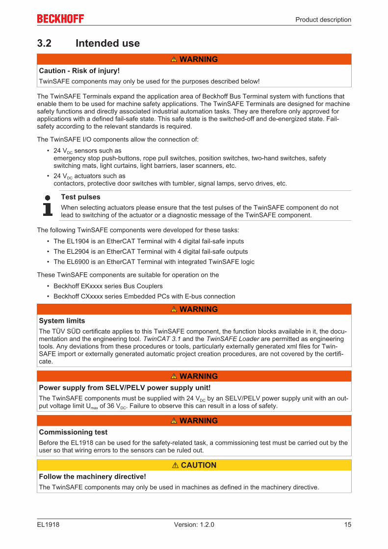
3.2 Intended use WARNING
Caution - Risk of injury!TwinSAFE components may only be used for the purposes described below!
The TwinSAFE Terminals expand the application area of Beckhoff Bus Terminal system with functions thatenable them to be used for machine safety applications. The TwinSAFE Terminals are designed for machinesafety functions and directly associated industrial automation tasks. They are therefore only approved forapplications with a defined fail-safe state. This safe state is the switched-off and de-energized state. Fail-safety according to the relevant standards is required.
The TwinSAFE I/O components allow the connection of:
• 24 VDC sensors such as emergency stop push-buttons, rope pull switches, position switches, two-hand switches, safetyswitching mats, light curtains, light barriers, laser scanners, etc.
• 24 VDC actuators such as contactors, protective door switches with tumbler, signal lamps, servo drives, etc.
Test pulsesWhen selecting actuators please ensure that the test pulses of the TwinSAFE component do notlead to switching of the actuator or a diagnostic message of the TwinSAFE component.
The following TwinSAFE components were developed for these tasks:
• The EL1904 is an EtherCAT Terminal with 4 digital fail-safe inputs• The EL2904 is an EtherCAT Terminal with 4 digital fail-safe outputs• The EL6900 is an EtherCAT Terminal with integrated TwinSAFE logic
These TwinSAFE components are suitable for operation on the
• Beckhoff EKxxxx series Bus Couplers• Beckhoff CXxxxx series Embedded PCs with E-bus connection
WARNINGSystem limitsThe TÜV SÜD certificate applies to this TwinSAFE component, the function blocks available in it, the docu-mentation and the engineering tool. TwinCAT 3.1 and the TwinSAFE Loader are permitted as engineeringtools. Any deviations from these procedures or tools, particularly externally generated xml files for Twin-SAFE import or externally generated automatic project creation procedures, are not covered by the certifi-cate.
WARNINGPower supply from SELV/PELV power supply unit!The TwinSAFE components must be supplied with 24 VDC by an SELV/PELV power supply unit with an out-put voltage limit Umax of 36 VDC. Failure to observe this can result in a loss of safety.
WARNINGCommissioning testBefore the EL1918 can be used for the safety-related task, a commissioning test must be carried out by theuser so that wiring errors to the sensors can be ruled out.
CAUTIONFollow the machinery directive!The TwinSAFE components may only be used in machines as defined in the machinery directive.

Product description
EL191816 Version: 1.2.0
CAUTIONEnsure traceability!The buyer has to ensure the traceability of the device via the serial number.
CAUTIONNote on approval according to EN 81-20, EN 81-22 and EN 81-50• The TwinSAFE components may only be used in machines that have been designed and installed in ac-
cordance with the requirements of the EN 60204-1 standard.• Provide a surge filter for the supply voltage of the TwinSAFE components against overvoltages. (Reduc-
tion to overvoltage category II)• EN 81 requires that in the case of devices with internal temperature monitoring, a stop must be reached
in the event of an overtemperature. In this case, passengers must be able to disembark (see EN 81-20chapter 5.10.4.3, for example). To ensure this, application measures are necessary. The internal termi-nal temperature of the TwinSAFE components can be read out by the user. There is a direct switch-off atthe maximum permissible temperature of the respective TwinSAFE component (see chapter Tempera-ture measurement). The user must select a temperature threshold below the maximum temperature such that a stop can bereached in all cases before the maximum temperature is reached. Information on the optimum terminalconfiguration can be found under Notes on the arrangement of TwinSAFE components and under Exam-ple configuration for temperature measurement.
• For the use of the TwinSAFE components according to EN 81-22 and EN 81-50, the conditions de-scribed in the manuals for achieving category 4 according to EN ISO 13849-1:2015 must be observed.
• The use of TwinSAFE components is limited to indoor applications.• Basic protection against direct contact must be provided, either by fulfilling protection class IP2X or by
installing the TwinSAFE components in a control cabinet which corresponds at least to protection classIP54 according to EN 60529.
• The ambient conditions regarding temperature, humidity, heat dissipation, EMC and vibrations, as speci-fied in the operating instructions under technical data, must be observed.
• The operating conditions in potentially explosive atmospheres (ATEX) are specified in the operating in-structions.
• The safe state (triggering) of the application must be the de-energized state. The safe state of the Twin-SAFE components is always the de-energized, switched-off state, and this cannot be changed.
• The service life specified in the operating instructions must be observed.• If the TwinSAFE component is operated outside the permissible temperature range, it changes to
"Global Shutdown" state.• The TwinSAFE components must be installed in a control cabinet with protection class IP54 according to
EN 60529, so that the requirement for contamination level 3 according to EN 60664-1 can be reduced tolevel 2.
• The TwinSAFE components must be supplied by a SELV/PELV power supply unit with a maximum volt-age of Umax <= 36 VDC.

Product description
EL1918 17Version: 1.2.0
3.3 Technical dataProduct designation EL1918Number of inputs 8Status display 12 (one green LED per input + 4 DIAG LEDs)Reaction time (read input/write to E-bus) typically: 4 ms,
maximally: see error reaction timeFault response time ≤ watchdog timeCable length between sensor and terminal unshielded max. 100 m (0.75 or 1 mm²)
shielded max. 100 m (0.75 or 1 mm²)Output current of the clock outputs typically 3 mA, max. 6.5 mAInput process image 7 bytesOutput process image 6 bytesSupply voltage of the EL1918 (PELV) 24 VDC (–15% / +20%)Signal voltage "0" inputs -3 V ... 5 V (EN 61131-2, type 3) see chapter Characteristic curve
of the inputs [} 19]Signal voltage "1" inputs 11 V ... 30 V (EN 61131-2, type 3) see chapter Characteristic
curve of the inputs [} 19]Current consumption of the module electronics at 24 V (without cur-rent consumption of sensors)
8 channels occupied: typically 29.6 mA (@28.8 VDC)0 channel occupied: typically 2.27 mA (@28.8 VDC)
Current consumption via E-bus 8 channels occupied: approx. 165 mAPower dissipation of the terminal typically 1.6 WElectrical isolation (between the channels) NoElectrical isolation (between the channels and the E-bus) YesInsulation voltage (between the channels and the E-bus, under com-mon operating conditions)
insulation tested with 500 VDC
Dimensions (W x H x D) 12 mm x 100 mm x 68 mmWeight approx. 50 gPermissible ambient temperature (operation) -25 °C to +55 °C (note chapter Temperature measurement
[} 23])Permissible ambient temperature (transport/storage) -40 °C to +70 °CPermissible air humidity 5% to 95%, non-condensingPermissible air pressure (operation/storage/transport) 750 hPa to 1100 hPa
(this corresponds to an altitude of approx. -690 m to 2450 mabove sea level, assuming an international standard atmos-phere)
Climate category according to EN 60721-3-3 3K3 (the deviation from 3K3 is possible only with optimal environmen-tal conditions and also applies only to the technical data whichare specified differently in this documentation)
Permissible contamination level according to EN 60664-1
Contamination level 2(note chapter Maintenance [} 48])
Inadmissible operating conditions TwinSAFE Terminals must not be used under the following oper-ating conditions:
• under the influence of ionizing radiation (exceeding thenatural background radiation)
• in corrosive environments
• in an environment that leads to unacceptablecontamination of the TwinSAFE component
EMC immunity / emission conforms to EN 61000-6-2 / EN 61000-6-4Vibration / shock resistance conforms to EN 60068-2-6 / EN 60068-2-27Shocks 15 g with pulse duration 11 ms in all three axesProtection class IP20Permitted operating environment In the control cabinet or terminal box, with minimum protection
class IP54 according to IEC 60529correct installation position see chapter Installation position and minimum distances [} 22]Approvals CE, TÜV SÜD

Product description
EL191818 Version: 1.2.0
3.4 Safety parametersCharacteristic numbers EL1918Lifetime [a] 20Prooftest Interval [a] not required 1
PFHD 3.00 E-09PFD 4.90 E-05MTTFD highDC highPerformance level PL eCategory 4HFT 1Element classification 2 Type B
1. Special proof tests are not required during the entire service life of the EL1918 EtherCAT terminal.2. Classification according to IEC 61508-2:2010 (chapter 7.4.4.1.2 and 7.4.4.1.3)
The EL1918 EtherCAT Terminal can be used for safety-related applications within the meaning ofIEC 61508:2010 up to SIL3 and EN ISO 13849-1:2015 up to PL e (Cat4).
Further information on calculating or estimating the MTTFD value from the PFHD value can be found in theTwinSAFE application manual or in EN ISO 13849-1:2015, Table K.1.
In terms of safety-related parameters, the Safety-over-EtherCAT communication is already considered with1% of SIL3 according to the protocol specification.
3.5 Safe inputThe safe inputs and associated clock outputs are implemented as a single channel for each module. Thishas the advantage that any channels, e.g. for a two-channel safe sensor, can be combined and used. Forerror evaluation of these two channels, the Module Fault Link active parameter of the two modules involvedmust be set to TRUE. This is the default state of this parameter.
DANGERClocked signals inside a sheathed cableIf clocked signals (clock outputs for the safe inputs) of different modules are used within a sheathed cable,a fault of one module, such as cross-circuit or external feed, must lead to the disconnection of all of thesemodules. This is achieved by setting the Module Fault Link active parameter for all modules involved. Thisparameter is set to TRUE by default.
DANGERSafe inputs in Kat.4 / PL eIf two safe input channels are to be used in a Category 4 structure, please ensure that you always combinean even and an odd channel number.

Product description
EL1918 19Version: 1.2.0
3.6 Characteristic curve of the inputsThe characteristic curve of the inputs is similar to type 3 according to EN 61131-2.
Fig. 5: Characteristic curve of the inputs
Product description
EL191820 Version: 1.2.0
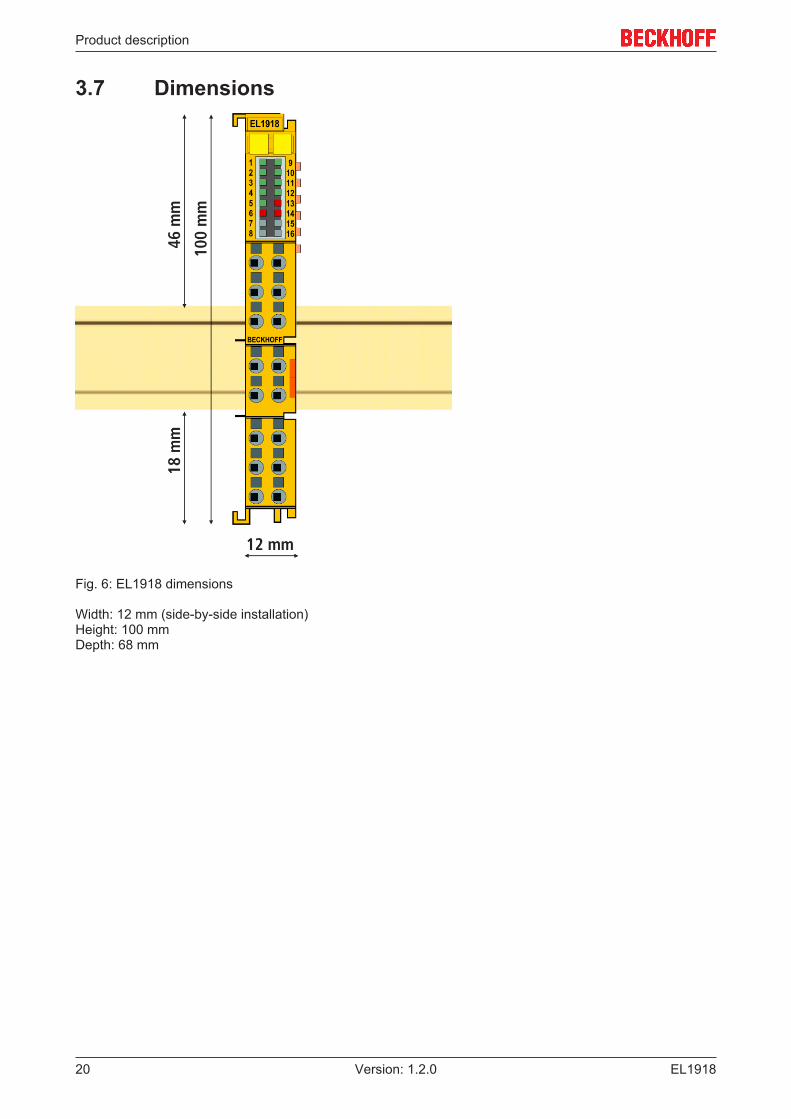
3.7 Dimensions
Fig. 6: EL1918 dimensions
Width: 12 mm (side-by-side installation)Height: 100 mmDepth: 68 mm

Operation
EL1918 21Version: 1.2.0
4 Operation
4.1 Environmental conditionsPlease ensure that the TwinSAFE components are only transported, stored and operated under the specifiedconditions (see technical data)!
WARNINGRisk of injury!The TwinSAFE components must not be used under the following operating conditions.• under the influence of ionizing radiation (that exceeds the level of the natural environmental radiation)• in corrosive environments• in an environment that leads to unacceptable soiling of the TwinSAFE component
NOTEElectromagnetic compatibilityThe TwinSAFE components comply with the current standards on electromagnetic compatibility with regardto spurious radiation and immunity to interference in particular.However, in cases where devices such as mobile phones, radio equipment, transmitters or high-frequencysystems that exceed the interference emissions limits specified in the standards are operated near Twin-SAFE components, the function of the TwinSAFE components may be impaired.
4.2 Installation
4.2.1 Safety instructionsBefore installing and commissioning the TwinSAFE components please read the safety instructions in theforeword of this documentation.
4.2.2 Transport / storageUse the original packaging in which the components were delivered for transporting and storing theTwinSAFE components.
CAUTIONNote the specified environmental conditionsPlease ensure that the digital TwinSAFE components are only transported and stored under the specifiedenvironmental conditions (see technical data).
4.2.3 Mechanical installation DANGER
Risk of injury!Bring the bus system into a safe, de-energized state before starting installation, disassembly or wiring ofthe devices!

Operation
EL191822 Version: 1.2.0
4.2.3.1 Instructions for ESD protection
NOTEDevices can be destroyed by electrostatic charging!The devices contain electrostatically sensitive components which can be damaged by im-proper handling.• Please ensure you are electrostatically discharged when handling the components; also
avoid touching the spring contacts directly (see illustration).• Avoid contact with highly insulating materials (synthetic fibers, plastic films etc.)• When handling the components, ensure good grounding of the environment (workplace,
packaging and persons)
• Each bus station must be terminated on the right side with the EL9011 or EL9012 end capto ensure the protection class and ESD protection.
Fig. 7: Spring contacts of Beckhoff I/O components
4.2.3.2 Control cabinet / terminal box
The TwinSAFE terminals must be installed in a control cabinet or terminal box with IP54 protection classaccording to IEC 60529 as a minimum.
4.2.3.3 Installation position and minimum distances
For the prescribed installation position the mounting rail is installed horizontally and the mating surfaces ofthe EL/KL terminals point toward the front (see illustration below). The terminals are ventilated from below,which enables optimum cooling of the electronics through convection. The direction indication “down”corresponds to the direction of positive acceleration due to gravity.

Operation
EL1918 23Version: 1.2.0
Fig. 8: Installation position and minimum distances
In order to ensure optimum convection cooling, the distances to neighboring devices and to control cabinetwalls must not be smaller than those shown in the diagram.
4.2.3.4 Temperature measurement
The temperature measurement consists of an EK1100 EtherCAT Coupler, to which EtherCAT Terminals areattached, based on the typical distribution of digital and analog signal types at a machine. On the EL6910 asafety project is active, which reads safe inputs and enables safe outputs during the measurement.
NOTEExternal heat sources / radiant heat / impaired convectionThe maximum permissible ambient temperature of 55°C was checked with the example configuration de-scribed above. Impaired convection, an unfavorable location near heat sources or an unfavorable configu-ration of the EtherCAT Terminals may result in overheating of the TwinSAFE components.The key parameter is always the maximum permitted internally measured temperature of 110°C, abovewhich the TwinSAFE components switch to safe state and report an error. The internal temperature can beread from the TwinSAFE components via CoE.

Operation
EL191824 Version: 1.2.0
4.2.3.5 Notes on the arrangement of TwinSAFE components
The following notes show favorable and unfavorable arrangement of the terminals in relation to thermal
aspects. Components with higher waste heat are marked with a red symbol and components with low
waste heat with a blue symbol .
EtherCAT coupler EK11xx and power supply terminal EL9410
The more terminals are connected behind an EtherCAT coupler or a power supply terminal, the higher is theE-Bus current, which must be supplied by their power supply units. As the current increases, the waste heatof the power supply units is also increased..
EL69x0
The EL69x0 has a rather high waste heat because it has a high internal clock and high logic power.
EL2904
The EL2904 has a rather high waste heat, due to the possibly high output current of the connectedactuators.
EL1904
Even the EL1904 has a rather high waste heat, although the external load by clock outputs and safe inputs israther low.

Operation
EL1918 25Version: 1.2.0
Thermally unfavorable arrangement of the TwinSAFE terminals
The following structure is rather unfavorable, since terminals with rather high waste heat are connecteddirectly to couplers or power supply terminals with high E-Bus load. The additional external heating of theTwinSAFE terminals by the adjacent power supply units increases the internal terminal temperature, whichcan lead to the maximum permissible temperature being exceeded. This leads to a diagnosis message"overtemperature”.
Fig. 9: Thermally unfavorable arrangement of the TwinSAFE terminals
Operation
EL191826 Version: 1.2.0
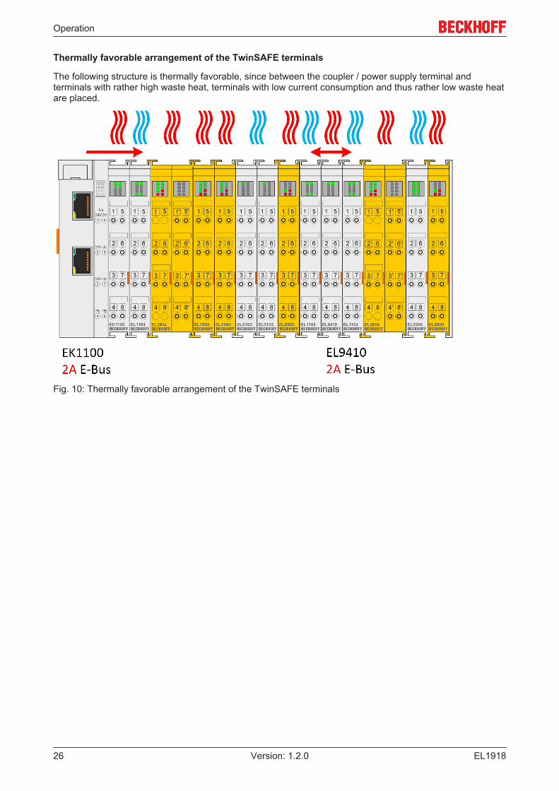
Thermally favorable arrangement of the TwinSAFE terminals
The following structure is thermally favorable, since between the coupler / power supply terminal andterminals with rather high waste heat, terminals with low current consumption and thus rather low waste heatare placed.
Fig. 10: Thermally favorable arrangement of the TwinSAFE terminals

Operation
EL1918 27Version: 1.2.0
4.2.3.6 Installation on mounting rails
WARNINGRisk of electric shock and damage of device!Bring the bus terminal system into a safe, powered down state before starting installation, disassembly orwiring of the Bus Terminals!
Mounting
Fig. 11: Installation on the mounting rail
The Bus Couplers and Bus Terminals are attached to commercially available 35 mm mounting rails (DIN railaccording to EN 60715) by applying slight pressure:
1. First attach the Fieldbus Coupler to the mounting rail.2. The Bus Terminals are now attached on the right-hand side of the Fieldbus Coupler. Join the compo-
nents with slot and key and push the terminals against the mounting rail, until the lock clicks onto themounting rail.If the terminals are clipped onto the mounting rail first and then pushed together without slot and key,the connection will not be operational! When correctly assembled, no significant gap should be visiblebetween the housings.
Fastening of mounting railsThe locking mechanism of the terminals and couplers protrudes into the profile of the mounting rail.When installing the components, make sure that the locking mechanism doesn't come into conflictwith the fixing bolts of the mounting rail. For fastening mounting rails with a height of 7.5 mm underthe terminals and couplers, use flat fastening components such as countersunk head screws orblind rivets.

Operation
EL191828 Version: 1.2.0
Disassembly
Fig. 12: Removal from mounting rail
Each terminal is secured by a lock on the mounting rail, which must be released for disassembly:
1. Pull down the terminal at its orange-colored straps from the mounting rail by approx. 1 cm. The raillocking of this terminal is automatically released, and you can now pull the terminal out of the Bus Ter-minal block with little effort.
2. To do this, grasp the unlocked terminal simultaneously at the top and bottom of the housing surfaceswith your thumb and index finger and pull it out of the Bus Terminal block.
4.2.4 Electrical installation
4.2.4.1 Connections within a Bus Terminal block
The electric connections between the Bus Coupler and the Bus Terminals are automatically realized byjoining the components:
Spring contacts (E-bus)
The six spring contacts of the E-bus deal with the transfer of the data and the supply of the Bus Terminalelectronics.
NOTEObserve the E-bus currentObserve the maximum current that your Bus Coupler can supply to the E-bus! Use the EL9410 Power Sup-ply Terminal if the current consumption of your terminals exceeds the maximum current that your Bus Cou-pler can feed to the E-bus supply.
Power contacts
The power contacts deal with the supply for the field electronics and thus represent a supply rail within theBus Terminal block. The power contacts are supplied via terminals on the Bus Coupler.
Note the connection of the power contactsDuring the design of a Bus Terminal block, the pin assignment of the individual Bus Terminals mustbe taken account of, since some types (e.g. analog Bus Terminals or digital 4-channel Bus Termi-nals) do not or not fully loop through the power contacts.Potential supply terminals (EL91xx, EL92xx) interrupt the power contacts and thus represent thestart of a new supply rail.

Operation
EL1918 29Version: 1.2.0
PE power contact
The power contact labelled PE can be used as a protective earth. For safety reasons this contact mates firstwhen plugging together, and can ground short-circuit currents of up to 125 A.
Fig. 13: PE power contact
CAUTIONInsulation testsNote that, for reasons of electromagnetic compatibility, the PE contacts are capacitatively coupled to themounting rail. This may lead to incorrect results during insulation testing or to damage on the terminal (e.g.disruptive discharge to the PE line during insulation testing of a consumer with a rated voltage of 230 V).For insulation testing, disconnect the PE supply line at the Bus Coupler or the Potential Supply Terminal! Inorder to decouple further feed points for testing, these Power Feed Terminals can be released and pulled atleast 10 mm from the group of terminals.
DANGERSerious risk of injury!The PE power contact must not be used for other potentials!
4.2.4.2 Overvoltage protection
If protection against overvoltage is necessary in your plant, provide a surge filter for the voltage supply to theBus Terminal blocks and the TwinSAFE terminals.

Operation
EL191830 Version: 1.2.0
4.2.4.3 HD housing wiring
Fig. 14: Connection of a cable to a terminal point
Up to 16 terminal points enable the connection of solid or finely stranded wires to the EtherCAT Terminal.The terminal points are spring-loaded.
Several conductors at one connectionIf it is necessary to connect several conductors to one connection, pre-connect them with terminalblocks, for example.
Solid and stranded wire conductors with ferrules can be inserted directly into the terminal point. Thiseliminates steps 1 and 3 in the above illustration. For all other conductor types, the terminal point must beopened with a screwdriver to establish the connection.
Connect the cables as follows:
1. Open a terminal point by pushing a screwdriver straight into thesquare opening above the terminal point as far as it will go. Do not turn or move the screwdriver backand forth (do not lever)
2. The wire can now be inserted into the round terminal opening without any force.3. The terminal closes automatically when the pressure is released, holding the wire safely and perma-
nently.
The permissible conductor cross-sections can be taken from the following table.
Wire cross-section (solid) 0.08 ... 1.5 mm2
Wire cross-section (stranded wire) 0.25 ... 1.5 mm2
Wire cross-section (core wire with ferrule) 0.14 ... 0.75 mm2
Strip length 8 ... 9 mm

Operation
EL1918 31Version: 1.2.0
4.2.4.4 Connection of the EL1918
Fig. 15: EL1918 connection
Terminal point Input Signal1 1 Input 1+ (clock output)2 Input 1- (safe input)3 3 Input 3+ (clock output)4 Input 3- (safe input)5 5 Input 5+ (clock output)6 Input 5- (safe input)7 7 Input 7+ (clock output)8 Input 7- (safe input)9 2 Input 2+ (clock output)10 Input 2- (safe input)11 4 Input 4+ (clock output)12 Input 4- (safe input)13 6 Input 6+ (clock output)14 Input 6- (safe input)15 8 Input 8+ (clock output)16 Input 8- (safe input)
Configurable inputsThe inputs 1 to 8 can be occupied as you want with normally closed contacts or normally open con-tacts. The corresponding analysis is carried out in the safety PLC. The input labeled Input x- is usedfor connecting OSSD sensors (self-testing sensors).

Operation
EL191832 Version: 1.2.0
4.2.4.5 Signal cables
Cable routing
Fig. 16: Cable routing
NOTERoute the signal cable separatelyThe signal cable must be routed separately from potential sources of interference, such as motor supply ca-bles, 230 VAC power cables etc.!Interference caused by cables routed in parallel can influence the signal form of the test pulses and thuscause diagnostic messages (e.g. sensor errors or OpenLoad errors).D: Distance between the cable ducts should be as large as possibleblue arrows: signal linered arrows: potential source of interference
The common routing of signals together with other clocked signals in a common cable also reduces themaximum propagation, since crosstalk of the signals can occur over long cable lengths and cause diagnosticmessages.

Operation
EL1918 33Version: 1.2.0
4.3 Configuration of the terminal in TwinCAT CAUTION
Do not change CoE objects!Do not change any of the CoE objects in the TwinSAFE terminals. Any modifications (e.g. via TwinCAT) ofthe CoE objects will permanently set the terminals to the Fail-Stop state or lead to unexpected behavior ofthe terminals!
4.3.1 Inserting a Bus CouplerSee TwinCAT automation software documentation.
4.3.2 Inserting a Bus TerminalSee TwinCAT automation software documentation.
4.3.3 Adding an EL1918An EL1918 is added in exactly the same way as any other Beckhoff EtherCAT Terminal. Open TwinSAFETerminals item in the list and select the EL1918.
Fig. 17: Adding an EL1918

Operation
EL191834 Version: 1.2.0
4.3.4 Address settings on TwinSAFE terminals with 1023 possibleaddresses
Fig. 18: Address settings on TwinSAFE terminals with 1023 possible addresses
The TwinSAFE address of the terminal is set via the 10-way DIP switch on the left-hand side of theTwinSAFE terminal. TwinSAFE addresses between 1 and 1023 are available.
DIP switch Address1 2 3 4 5 6 7 8 9 10ON OFF OFF OFF OFF OFF OFF OFF OFF OFF 1OFF ON OFF OFF OFF OFF OFF OFF OFF OFF 2ON ON OFF OFF OFF OFF OFF OFF OFF OFF 3OFF OFF ON OFF OFF OFF OFF OFF OFF OFF 4ON OFF ON OFF OFF OFF OFF OFF OFF OFF 5OFF ON ON OFF OFF OFF OFF OFF OFF OFF 6ON ON ON OFF OFF OFF OFF OFF OFF OFF 7... ... ... ... ... ... ... ... ... ... ...ON ON ON ON ON ON ON ON ON ON 1023
WARNINGTwinSAFE addressEach TwinSAFE address may only be used once within a network / a configuration!The address 0 is not a valid TwinSAFE address!

Operation
EL1918 35Version: 1.2.0
4.3.5 Alias devicesThe communication between the safety logic and the I/O level is realized via an alias level. At this alias level(subnode Alias Devices) corresponding alias devices are created for all safe inputs and outputs, and also forstandard signal types. For the safe inputs and outputs, this can be done automatically via the I/Oconfiguration.
The connection- and device-specific parameters are set via the alias devices.
Fig. 19: Starting the automatic import from the I/O configuration
If the automatic import is started from the I/O configuration, a selection dialog opens, in which the individualterminals to be imported can be selected.
Fig. 20: Selection from the I/O tree
The alias devices are created in the safety project when the dialog is closed via OK.
Alternatively, the user can create the alias devices individually. To this end select Add and New item fromthe context menu, followed by the required device.

Operation
EL191836 Version: 1.2.0
Fig. 21: Creating alias devices by the user
4.3.6 EL1918 parameters in TwinCATAfter creating the alias device, it can be parameterized according to the user specifications.
The FSoE address is set under the Linking tab, and the link to the physical device is created.
Fig. 22: Linking tab of the alias device
Under the Connection tab you can make further settings, e.g. the mapping of the info data or the behavior incase of a module error.

Operation
EL1918 37Version: 1.2.0
Fig. 23: Connection tab of the alias device
The Safety Parameters tab contains the parameters of the EL1918 to be set. The parameters are setseparately for each input. Objects 0x8000 and 0x8001 are available for input 1. For all other inputs, the CoEindex is increased by 10 hex each, so that objects 0x8070 and 0x8071 are available for input 8.
Fig. 24: EL1918 parameters

Operation
EL191838 Version: 1.2.0
Index Name Default value/unit
Description
80x0:01 ModuloDiagTestPulse 0x00 / integer Modulo value for the frequency ofgenerating a test pulse.0 -> every time1 -> every second time...
80x0:02 MultiplierDiagTestPulse 0x01 / integer Length of the test pulse in multiples of400 µs
80x0:04 Diag TestPulse active TRUE / Boolean Activation of test pulses for thecorresponding input module
80x0:05 Module Fault Link active TRUE / Boolean If a module error occurs in this module, amodule error is also set for all othermodules of this TwinSAFE component forwhich this parameter is also set to TRUE.
80x1:01 InputFilterTime 0x000A / 0.1 ms Input filter of the safe input. Following thistime the internal input signal changes tothe applied signal state.
80x1:02 DiagTestPulseFilterTime 0x0002 / 0.1 ms Input filter for the test pulse signal
4.3.7 Process image of the EL1918The process image of the EL1918 consists of 7 bytes process data in the input and 6 bytes process data inthe output.
Fig. 25: Process image of the EL1918
The assignment of the individual signals in the safe data is listed in the following table.
Operation
EL1918 39Version: 1.2.0
Name Processimage
Bit position Description
FSIN Module1.Input IN 0.0 Safe input 1FSIN Module1.Module Fault IN 0.1 Module error information for input 1FSIN Module2.Input IN 0.2 Safe input 2FSIN Module2.Module Fault IN 0.3 Module error information for input 2FSIN Module3.Input IN 0.4 Safe input 3FSIN Module3.Module Fault IN 0.5 Module error information for input 3FSIN Module4.Input IN 0.6 Safe input 4FSIN Module4.Module Fault IN 0.7 Module error information for input 4FSIN Module5.Input IN 1.0 Safe input 5FSIN Module5.Module Fault IN 1.1 Module error information for input 5FSIN Module6.Input IN 1.2 Safe input 6FSIN Module6.Module Fault IN 1.3 Module error information for input 6FSIN Module7.Input IN 1.4 Safe input 7FSIN Module7.Module Fault IN 1.5 Module error information for input 7FSIN Module8.Input IN 1.6 Safe input 8FSIN Module8.Module Fault IN 1.7 Module error information for input 8FSIN Module 1.ErrAck OUT 0.0 Error acknowledge for safe input 1FSIN Module 2.ErrAck OUT 0.1 Error acknowledge for safe input 2FSIN Module 3.ErrAck OUT 0.2 Error acknowledge for safe input 3FSIN Module 4.ErrAck OUT 0.3 Error acknowledge for safe input 4FSIN Module 5.ErrAck OUT 0.4 Error acknowledge for safe input 5FSIN Module 6.ErrAck OUT 0.5 Error acknowledge for safe input 6FSIN Module 7.ErrAck OUT 0.6 Error acknowledge for safe input 7FSIN Module 8.ErrAck OUT 0.7 Error acknowledge for safe input 8
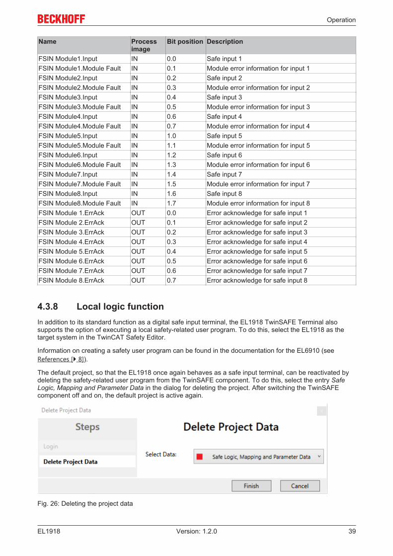
4.3.8 Local logic functionIn addition to its standard function as a digital safe input terminal, the EL1918 TwinSAFE Terminal alsosupports the option of executing a local safety-related user program. To do this, select the EL1918 as thetarget system in the TwinCAT Safety Editor.
Information on creating a safety user program can be found in the documentation for the EL6910 (seeReferences [} 8]).
The default project, so that the EL1918 once again behaves as a safe input terminal, can be reactivated bydeleting the safety-related user program from the TwinSAFE component. To do this, select the entry SafeLogic, Mapping and Parameter Data in the dialog for deleting the project. After switching the TwinSAFEcomponent off and on, the default project is active again.
Fig. 26: Deleting the project data

Operation
EL191840 Version: 1.2.0
4.3.9 Project design limits of EL1918Project design limitsThe maximum project design size for EL1918 is determined by the available memory. This is man-aged dynamically. The values specified in the following table are therefore only guide values andmay differ from the actual values, depending on the safety project.
NOTEExecution time of the logic functionThe execution time of the logic program - with identical logic program - will typically be longer compared tothe EL6910, since the safe I/O signals must be processed additionally. This also has a corresponding effecton the processing of the I/O signals, since with increasing project size these can only be evaluated with alower frequency.
Process image size max. 1486 byte per data direction (maximum memory size 0x1E00 for 3 buffers, ie with the same size ofinput and output process data, a maximum size of 1280 bytes per datadirection is possible. Only straight start addresses are possible, so fillbytes must be taken into account)
TwinSAFE connections 128 max. (up to 255 CRCs in total; 1 CRC is required for a TwinSAFE connectionwith 1 or 2 byte safe data.)
Safe data per TwinSAFEconnection
maximum 126 byte (telegram length 255 byte)
TwinSAFE blocks maximum 512 (when using ESTOP function blocks with complete inputand output mapping, other function blocks can lead to a smallermaximum number)
TwinSAFE groups 128 max.TwinSAFE user 40 max.Standard PLC inputs dynamic (memory-dependent), max. 1484 byteStandard PLC outputs dynamic (memory-dependent), max. 1484 byte
NOTEProject developmentTwinCAT 3.1 Build 4022.25 or newer is required to use the internal logic functions. If the EL1918 is used asTwinSAFE slave with the default project, at least an EL6910, EK1960 or newer logic component is requiredas TwinSAFE master.
4.4 TwinSAFE reaction timesThe TwinSAFE terminals form a modular safety system that exchanges safety-oriented data via the Safety-over-EtherCAT protocol. This chapter is intended to help you determine the system's reaction time from thechange of signal at the sensor to the reaction at the actuator.
Typical reaction time
The typical reaction time is the time that is required to transmit information from the sensor to the actuator, ifthe overall system is working without error in normal operation.

Operation
EL1918 41Version: 1.2.0
Fig. 27: Typical reaction time
Definition DescriptionRTSensor Reaction time of the sensor until the signal is provided at the interface. Typically supplied by
the sensor manufacturer.RTInput Reaction time of the safe input, such as EL1904 or EP1908. This time can be found in the
technical data. In the case of the EL1904 it is 4 ms.RTComm Reaction time of the communication This is typically 3x the EtherCAT cycle time, because
new data can only be sent in a new Safety-over-EtherCAT telegram. These times dependdirectly on the higher-level standard controller (cycle time of the PLC/NC).
RTLogic Reaction time of the logic terminal. This is the cycle time of the logic terminal and typicallyranges from 500 µs to 10 ms for the EL6900, depending on the size of the safety project.The actual cycle time can be read from the terminal.
RTOutput Reaction time of the output terminal. This typically lies within the range of 2 to 3 ms.RTActor Reaction time of the actuator. This information is typically supplied by the actuator
manufacturerWDComm Watchdog time of the communication
This results in the following equation for the typical reaction time:
with, for example
Worst-case reaction time
The worst case reaction time is the maximum time required to switch off the actuator in the case of an error.
Fig. 28: Worst-case reaction time

Operation
EL191842 Version: 1.2.0
This assumes that a signal change occurs at the sensor and is transmitted to the input. A communicationerror occurs at precisely the moment when the signal is to be transferred to the communication interface.This is detected by the logic following the watchdog time of the communication link. This information shouldthen be transferred to the output, but a further communication error occurs here. This error is detected at theoutput following the expiry of the watchdog time and leads to the switch-off.
This results in the following equation for the worst-case reaction:
with, for example

Operation
EL1918 43Version: 1.2.0
4.5 Diagnosis
4.5.1 Status LEDs
Fig. 29: Status LEDs
LED Color DescriptionInput 1 green Status display for the respective input
LED lights up: Input is setLED not lit: Input is not set
Input 2Input 3Input 4Input 5Input 6Input 7Input 8
4.5.2 Diagnostic LEDs
Diagnostic LEDs
LED lit flashing offDiag 1(green)
Environment variables,operating voltage and internaltests are in the valid range• If Diag 2 flashes, a logic
error code applies
- Environment variables,operating voltage and internaltests are outside the validrange• If Diag 2 flashes, an
environment error codeapplies
Diag 2(red)
Together with Diag 3 and 4:Global shutdown1) hasoccurred. (see diag history ofthe TwinSAFE components)
Logic or environment errorcode according to Diag1 andtables below is output
Together with Diag 3 and 4:Global fault1) has occurred. (seediag history of the TwinSAFEcomponents)
Diag 3(red)
Global fault or global shutdownon µC11)
- No global fault or globalshutdown on µC11)
Diag 4(red)
Global fault or global shutdownon µC21)
- No global fault or globalshutdown on µC21)

Operation
EL191844 Version: 1.2.0
1. A global fault permanently disables the TwinSAFE component, so that it has to be replaced. A globalshutdown temporarily disables the TwinSAFE component. The error can be reset by switching off andback on again.
Logic error codes of LED Diag 2 (if LED Diag 1 is lit)
FlashingCode
Description
1 Function block error in one of the TwinSAFE groups2 Communication error in one of the TwinSAFE groups3 Error combination: Function block and communication4 General error in one of the TwinSAFE groups5 Error combination: General and function block6 Error combination: General and communication7 Error combination: General, function block and communication
Environment error codes of LED Diag 2 (if LED Diag 1 is off)
FlashingCode
Description
1 Maximum supply voltage µC1 exceeded2 Supply voltage µC1 below minimum value3 Maximum supply voltage µC2 exceeded4 Supply voltage µC2 below minimum value5 Maximum internal temperature exceeded6 Internal temperature below minimum value7 Valid temperature difference between µC1 and µC2 exceeded8 not used9 not used10 General error
4.5.3 Flash code displayLED Display Descriptionflashing 400 ms ON / 400 ms OFF
1 second pause between the flash codes
flickering 50 ms ON / 50 ms OFF
4.5.4 Diagnosis HistoryThe diagnostic history of the TwinSAFE devices that support this function is implemented in accordance withthe ETG guideline ETG.1020 Chapter 13 "Diagnosis Handling". The diagnostic messages are saved by theTwinSAFE device in a dedicated CoE object under 0x10F3 and can be read out by the application or byTwinCAT.
Both the control entries and the history itself can be found in the CoE object 0x10F3. The entry NewestMessage (0x10F3:02) contains the subindex of 0x10F3, which contains the latest diagnostic message, e.g.0x06 for diagnostic message 1.

Operation
EL1918 45Version: 1.2.0
Index 10F3hex Diagnosis History
Index (hex) Name Meaning Data type Flags Default10F3:0 Diagnosis
History10F3:01 Maximum
MessagesMaximum number of stored messages. Amaximum of 64 messages can be stored.After that the respective oldest messagesare overwritten.
UINT8 RO 0x40 (64dec)
10F3:02 NewestMessage
Subindex of the latest message UINT8 RO 0x00 (0dec)
10F3:03 NewestAcknowledgedMessage
Subindex of the last confirmed message UINT8 RW 0x00 (0dec)
10F3:04 NewMessagesAvailable
Indicates that a new message is available BOOLEAN RO 0x00 (0dec)
10F3:05 Flags Set via the startup list. If set to 0x0001, thediagnostic messages are additionally sentby emergency to the EtherCAT master
UINT16 RW 0x0000 (0dec)
10F3:06 DiagnosisMessage 001
Diagnostic message 1 BYTE[32] RO {0}
... ... ... ... ... ...10F3:45 Diagnosis
Message 064Diagnostic message 64 BYTE[32] RO {0}
Structure of the diagnostic messages• DiagCode (4 bytes) – in this case always 0x 0000 E000• Flags (2 bytes) - diagnosis type (info, warning or error), timestamp and number of parameters
contained (see the following table)• Text ID (2 bytes) – ID of the diagnostic message as a reference to the message text from the ESI/XML• Timestamp (8 bytes) – local slave time in ns since switching on the TwinSAFE device• dynamic parameters (16 bytes) – parameters that can be inserted in the message text (see following
table)
Flags in diagnostic messages
Data type Offset DescriptionUINT16 Bits 0 to 3 DiagType (value)
0 Info message1 Warning message2 Error message3…15 reserved
Bit 4 If the bit = 1, the timestamp contained in the message is the local timestamp of theTwinSAFE device. The age of the diagnostic message can be deduced bycalculation with the current timestamp from the CoE object 0x10F8.
Bits 5 to 7 reservedBits 8 to 15 Number of parameters in this diagnostic message

Operation
EL191846 Version: 1.2.0
Dynamic parameters in the diagnostic messages
Type Data type DescriptionFlags parameter 1 UINT16 Describes the type of parameter 1
Bits 12 to 15 =0
Bits 0 to 11 = data type of parameter 10x0001 - BOOLEAN0x0002 - INT80x0003 - INT160x0004 - INT320x0005 - UINT80x0006 - UINT160x0007 - UINT320x0008 - REAL320x0011 - REAL640x0015 - INT640x001B - UINT64Text parameters and formats arespecified in ETG.2000.
Parameter 1 Data type in accordance withflags
Value of parameter 1
Flags parameter 2 UINT16 see Flags parameter 1Parameter 2 Data type in accordance with
flagsValue of parameter 2
...
The diagnostic messages are saved in text form in the ESI/XML file belonging to the TwinSAFE device. Onthe basis of the Text ID contained in the diagnostic message, the corresponding plain text message can befound in the respective languages. The parameters can be inserted in the appropriate positions. In thefollowing example, %x is used for a hexadecimal representation of the parameters.
Fig. 30: ESI/XML message text
Via the entry New Messages Available the user receives information that new messages are available. Themessages can be read out via CompleteAccess (a CoE read command for the complete CoE object0x10F3). The New Messages Available bit is reset after reading the messages.
The sending of emergency messages to the EtherCAT master is activated by adding the CoE object0x10F3:05 to the startup list (Transition IP, value 0x0001). If new diagnostic messages arrive, they areentered in object 0x10F3 and additionally sent by emergency to the EtherCAT master.
Fig. 31: Startup list

Operation
EL1918 47Version: 1.2.0
4.5.5 Diag History tabAll errors occurring within the TwinSAFE components are stored in their diag history. The diag history can beviewed by selecting the corresponding TwinSAFE component in the I/O tree structure and then selecting theDiag History tab. Use the Update History button to fetch the current data from the TwinSAFE component.Errors within the logic, the function blocks, the connections or the component itself are stored with acorresponding time stamp.
Fig. 32: Diag history
Use the Advanced… button to open the advanced settings. Here, the user can customize the behavior of thediag history.
Fig. 33: Diag history – advanced settings

Operation
EL191848 Version: 1.2.0
Advanced Settings
Setting DescriptionMessage Types • disable Info
Messages with status Info are not stored in the diag history• disable Warnings
Messages with status Warning are not stored in the diag history• disable Errors
Messages with status Error are not stored in the diag historyEmergency In addition to saving the message in the diag history, an emergency object
is also sent and displayed in the TwinCAT logger window.Overwrite / Acknowledge Mode This setting is currently not supported.
4.6 Maintenance
Maintenance
The TwinSAFE components are maintenance-free!
Environmental conditions
WARNINGObserve the specified environmental conditions!Please ensure that the TwinSAFE components are only stored and operated under the specified conditions(see technical data).
If the TwinSAFE component is operated outside the permitted temperature range it will switch to GlobalShutdown state.
Cleaning
Protect the TwinSAFE component from unacceptable soling during operation and storage!
If the TwinSAFE component was subjected to unacceptable soiling it may no longer be operated!
WARNINGHave soiled terminals checked!Cleaning of the TwinSAFE component by the user is not permitted!Please send soiled terminals to the manufacturer for inspection and cleaning!

Operation
EL1918 49Version: 1.2.0
4.7 Service lifeThe TwinSAFE terminals are designed for a service life of 20 years.
Due to the high diagnostic coverage within the lifecycle no special proof tests are required.
The TwinSAFE terminals bear a date code, which is composed as follows:
Date code: CW YY SW HW
Legend:CW: Calendar week of manufactureYY: Year of manufactureSW: Software versionHW: Hardware version
Sample: Date Code 17 11 05 00Calendar week: 17Year: 2011Software version: 05Hardware version: 00
In addition the TwinSAFE terminals bear a unique serial number.
Fig. 34: Unique serial number of a TwinSAFE terminal
4.8 Decommissioning DANGER
Serious risk of injury!Bring the bus system into a safe, de-energized state before starting disassembly of the devices!
Disposal
In order to dispose of the device, it must be removed and fully dismantled.
• Housing components (polycarbonate, polyamide (PA6.6)) are suitable for plastic recycling.• Metal parts can be sent for metal recycling.• Electronic parts such as disk drives and circuit boards must be disposed of in accordance with national
electronics scrap regulations.

Operation
EL191850 Version: 1.2.0
4.9 Firmware update of TwinSAFE productsFor TwinSAFE products there is the option of performing a firmware update via the EtherCAT interface. Thecomplete firmware of the TwinSAFE component is deleted and replaced by a new version.
The latest firmware can be downloaded from the Beckhoff website or requested from Beckhoff Support. Theversions are available in an encrypted form and can only be loaded onto the matching TwinSAFE product.An incorrect firmware file is rejected by the respective TwinSAFE product.
Prerequisite for a firmware update
DANGERPut the machine into a safe state!A firmware update stops the current processing of the firmware of the TwinSAFE product. It is essential thatyou switch the TwinSAFE system to the safe state before you start an update. All safe outputs must be in a safe, de-energized state. If hanging or pulling loads are present on the ma-chine or the TwinSAFE system, these must also be brought into a safe state through external safety mea-sures if necessary.
DANGERMonitor the machine state!It is necessary that you have control over the machine, i.e. you can see it and thus ensure that it is in a safestate and that a firmware update can be carried out without endangering the operators or other personnel.
NOTEAvoid communication interruptions during the downloadPlease avoid disconnecting the EtherCAT connection while downloading the firmware under any circum-stances. If a communication error does occur, the TwinSAFE product may subsequently be unusable andmust be sent to the Beckhoff Service.
WARNINGDefault project for TwinSAFE I/O components with local logic function!After a firmware update, any implemented default project starts automatically. An EK1960, for example,would start up as a TwinSAFE I/O slave after a firmware update.
NOTEFirmware update of TwinSAFE logicsIf a firmware update is performed for a TwinSAFE logic component, e.g. on a TwinSAFE logic EL6910, thesafety-related user program must be reloaded to the TwinSAFE logic after the update.
EtherCAT communicationWhen an EtherCAT component is updated, it is switched to BOOTSTRAP mode. This can have aneffect on the EtherCAT communication with other EtherCAT devices.

Operation
EL1918 51Version: 1.2.0
Performing the firmware update
Click the button (1) in the TwinCAT system to enter Config mode. Confirm the query with OK (2). After that afurther window appears which must be confirmed with Yes (Ja) (3). Deactivate the "Free Run" with No (Nein)(4). The system is now in "Configuration mode".
Fig. 35: Firmware update of TwinSAFE products - Part 1

Operation
EL191852 Version: 1.2.0
To perform the firmware update, select the "Online" tab (6) for the "EtherCAT Device" (5). If you want toupdate several components, you can select the corresponding components (7) together; for individualcomponents, select only these. Subsequently, click with the right mouse button inside the selected area andselect the command "Firmware Update..." (8) in the command overview.
Fig. 36: Firmware update of TwinSAFE products - Part 2
In the place where you have stored the desired firmware version, select the firmware file (9) and click"Open" (10). Confirm the window that then opens with "OK" (11); the firmware update is then performed.After successful completion you must click OK (12) in the concluding "Function Succeeded" window. Youcan then switch the system back to Run mode and use the TwinSAFE system.
Fig. 37: Firmware update of TwinSAFE products - Part 3

Appendix
EL1918 53Version: 1.2.0
5 Appendix
5.1 Support and ServiceBeckhoff and their partners around the world offer comprehensive support and service, making available fastand competent assistance with all questions related to Beckhoff products and system solutions.
Beckhoff's branch offices and representatives
Please contact your Beckhoff branch office or representative for local support and service on Beckhoffproducts!
The addresses of Beckhoff's branch offices and representatives round the world can be found on her internetpages:http://www.beckhoff.com
You will also find further documentation for Beckhoff components there.
Beckhoff Headquarters
Beckhoff Automation GmbH & Co. KG
Huelshorstweg 2033415 VerlGermany
Phone: +49(0)5246/963-0Fax: +49(0)5246/963-198e-mail: [email protected]
Beckhoff Support
Support offers you comprehensive technical assistance, helping you not only with the application ofindividual Beckhoff products, but also with other, wide-ranging services:
• support• design, programming and commissioning of complex automation systems• and extensive training program for Beckhoff system components
Hotline: +49(0)5246/963-157Fax: +49(0)5246/963-9157e-mail: [email protected]
Beckhoff Service
The Beckhoff Service Center supports you in all matters of after-sales service:
• on-site service• repair service• spare parts service• hotline service
Hotline: +49(0)5246/963-460Fax: +49(0)5246/963-479e-mail: [email protected]

Appendix
EL191854 Version: 1.2.0
5.2 Certificates

List of figures
EL1918 55Version: 1.2.0
List of figuresFig. 1 Slot and key system and screwless (spring-loaded) connection system..................................... 9Fig. 2 Bus Coupler (EtherCAT).............................................................................................................. 10Fig. 3 Overview of EtherCAT Terminals ................................................................................................ 11Fig. 4 EL1918 – TwinSAFE Terminal with 8 fail-safe inputs.................................................................. 14Fig. 5 Characteristic curve of the inputs ................................................................................................ 19Fig. 6 EL1918 dimensions ..................................................................................................................... 20Fig. 7 Spring contacts of Beckhoff I/O components............................................................................... 22Fig. 8 Installation position and minimum distances ............................................................................... 23Fig. 9 Thermally unfavorable arrangement of the TwinSAFE terminals ................................................ 25Fig. 10 Thermally favorable arrangement of the TwinSAFE terminals .................................................... 26Fig. 11 Installation on the mounting rail ................................................................................................... 27Fig. 12 Removal from mounting rail ......................................................................................................... 28Fig. 13 PE power contact......................................................................................................................... 29Fig. 14 Connection of a cable to a terminal point .................................................................................... 30Fig. 15 EL1918 connection ...................................................................................................................... 31Fig. 16 Cable routing ............................................................................................................................... 32Fig. 17 Adding an EL1918 ....................................................................................................................... 33Fig. 18 Address settings on TwinSAFE terminals with 1023 possible addresses ................................... 34Fig. 19 Starting the automatic import from the I/O configuration ............................................................. 35Fig. 20 Selection from the I/O tree........................................................................................................... 35Fig. 21 Creating alias devices by the user............................................................................................... 36Fig. 22 Linking tab of the alias device...................................................................................................... 36Fig. 23 Connection tab of the alias device............................................................................................... 37Fig. 24 EL1918 parameters ..................................................................................................................... 37Fig. 25 Process image of the EL1918...................................................................................................... 38Fig. 26 Deleting the project data.............................................................................................................. 39Fig. 27 Typical reaction time.................................................................................................................... 41Fig. 28 Worst-case reaction time ............................................................................................................. 41Fig. 29 Status LEDs................................................................................................................................. 43Fig. 30 ESI/XML message text ................................................................................................................ 46Fig. 31 Startup list.................................................................................................................................... 46Fig. 32 Diag history.................................................................................................................................. 47Fig. 33 Diag history – advanced settings................................................................................................. 47Fig. 34 Unique serial number of a TwinSAFE terminal............................................................................ 49Fig. 35 Firmware update of TwinSAFE products - Part 1 ........................................................................ 51Fig. 36 Firmware update of TwinSAFE products - Part 2 ........................................................................ 52Fig. 37 Firmware update of TwinSAFE products - Part 3 ........................................................................ 52

![Manual PLC Lib: Tc2 SMI - Beckhoff Automationftp.beckhoff.com/download/Document/automation/... · motor side. FB_SMIPos1Read [}Reads the fixed position 22] Pos1 configured on the](https://img.pdfslide.net/doc/110x75/603927279e3e2c4dd0295d03/manual-plc-lib-tc2-smi-beckhoff-motor-side-fbsmipos1read-reads-the-fixed.jpg)