Embed Size (px)
Citation preview
OPERATING INSTRUCTIONS FOR
MEDECO® KEY MACHINES
FOR MEDECO ORIGINAL, BIAXIAL®, MEDECO3®, KEYMARK® CLASSIC &
KEYMARK X4® PRODUCTS
MEDECO® HIGH SECURITY LOCKS ASSUMES NO RESPONSIBILITY FOR INJURY OR PROPERTY DAMAGE AS A RESULT OF IMPROPER USE OF MEDECO® KEY MACHINES. READ AND UNDERSTAND ALL INSTRUCTIONS AND SAFETY
PRECAUTIONS BEFORE INSTALLING OR OPERATING ANY MEDECO® KEY MACHINE.

2
CONTENTS
Introduction……………………………………………………………… 3
Potential Hazards………………………………………………………….. 4
Installation Procedure…………………………………………………… 5
Operating Instructions………………………………………………….. 6
Original Key Machine……………………………………………. 6
Biaxial Key Machine………………………………………………. 7
Universal Key Machine (Original Product)…………….. 8
Universal Key Machine (Biaxial Product)……………….. 9
KeyMark Classic & KeyMark x4 Key Machine……………… 10
Maintenance and Adjustment………………………………………. 11
Adjusting Lever Resistance………………………………. 11
Checking Accuracy of Cut…………………………………. 11
Adjusting Cutter………………………………………………. 14
Adjusting Depth of Cut…………………………………….. 14
Adjusting Shoulder Spacing……………………………… 14
Changing Cutter……………………………………………….. 15
Cleaning Vise Jaw……………………………………………… 16
Installing Quick Change Pin……………………………….. 16
Ordering Instructions……………………………………………………. 17
Key Machine Parts…………………………………………….. 18
3
INTRODUCTION The Medeco and KeyMark key machines are designed and built to precision standards at Medeco solely for cutting Medeco or KeyMark keys; they do this by means of a rotating cutter powered by an integral motor. The cutter is positioned for each cut by a precision ground dial to determine the depth, and on angled-cut machines, the angle of each cut is set by an angling lever. The key machine is a high quality, extra heavy duty piece of equipment and incorporates many safety and mechanical features to ensure easy, hazard free operation.
Several models are available: the original key machine cuts Medeco original keys and Medeco3 keys on original keyways, and the Biaxial key machine (with prefix B on the serial number) cuts Medeco Biaxial and Medeco3 Biaxial keys. The KeyMark Classic key machine is available for cutting KeyMark Classic keys and the KeyMark x4 machine cuts KeyMark x4 keys. The universal key machine (with prefix U on the serial number) cuts original and Biaxial keys and all Medeco3 keys, but does not cut KeyMark or KeyMark x4 keys. Factory conversion of the original and the Biaxial machines to the universal version is available.
An optional air-powered slide assembly for providing vertical motion of the cutter wheel is available for the key machine. This option may be purchased with new key machines or adapted to an existing machine through factory modification.
4
POTENTIAL HAZARDS Although every precaution has been taken to guard against hazards, they may still exist if the machine is used improperly or if the safety features are removed or disabled. Never operate the machine without understanding its complete and safe operation. It is the machine owner’s responsibility to provide proper safety devices and equipment to safeguard the operator from harm and to ensure at all times that the machine meets all current government safety codes and standards. Observance of the potential hazards and installation maintenance and use of the machine in compliance with the instructions contained in this booklet are essential for safe operation. The potential hazards are marked as follows: Caution: Do not operate without guards in place! The potential hazards on the key machine have been reduced as much as possible by the placement of guards. Usage of the machine without the guards in place exposes the operator to potential serious injury from the rotating cutter and belt. The key machine should never be used without the guards in place. Caution: Rotating cutter! Although the cutter is well guarded, it still remains a potential hazard as it is extremely sharp and has a high rate of rotation when the power is on. Under no circumstances should anyone reach under the guard, even when the cutter is stationary. The key machine should never be used without the guards in place. Caution: Cutter will rotate on resumption of power if switch is in the “On” position! If the power is interrupted for any reason while the power switch is in the “On” position (cutter rotating), the cutter will resume rotation when the power is restored, unless the power switch is moved to the “Off” position. This should be noted, especially if the power cord is disconnected and the guards removed to change the cutter; the power switch should always be moved to the “Off” position before power is reconnected. Caution: Rotating belt! The drive belt from the motor has several potential pinch points and a high rate of rotation. Under no circumstances should any object be inserted under the guard while the power switch is in the “On” position. The key machine should never be used without the guards in place. Caution: Turn motor off before loading and unloading keys. Ensure keys are clamped before cutting! Because of the potential for a key to touch the rotating cutter and be thrown from the machine at a high speed, the motor should be turned off before keys are loaded or unloaded. The potential for keys to be thrown by the rotating cutter also exists if the keys are not clamped tightly in the vice. Always check that the clamp is tight before cutting a key. Warning: Pull lever handle in a vertical direction! Do not apply side pressure to handle! The handle which lowers the cutter is designed to be used with vertical pressure only. Any sideways pressure should be avoided, as it puts unnecessary strain on the handle itself and the linkage. Caution: Do not lift the key machine by the handle! The handles on the key machine are not designed to support the weight of the machine and therefore should not be used for lifting purposes. Failure to observe this caution may result in damage to the machine or possible injury if the handles fracture. The machine should be lifted by the base and motor only. Caution: Always ensure that the electrical requirements of the key machine motor match the electrical system into which the machine is being plugged! Key machines with 115V 60Hz motors are intended for use in North America, and key machines with 220V 50Hz are intended for use in Europe. Always check that the wiring of the electrical system in which the machine will be used match the label on the motor. Plugging a key machine into an improper system may result in damage to the machine or injury to the user.
5
INSTALLATION PROCEDURE Remove the key machine from the packing crate by lifting from the base or the motor. The machine should not be lifted by using any of the handles or guards. It should be installed on a flat, stable surface capable of supporting the ~100lb weight of the machine. Holes for optional use of mounting bolts are drilled in the base.
Install the appropriate power cord into the pigtail on the back of the motor, and plug into a grounded electrical source, ensuring that the power switch is in the “off” position before connecting power. Route the electrical cable directly from the back of the motor so that no interference with the cutter is possible. The electrical cord should be checked periodically for nicks and cuts in the insulation and exposure of bare wires; if the cord becomes worn in this way, it should be replaced to minimize the possibility of electrical shock. Never pull the machine by means of the power cord. For installation of a key machine with the optional air-powered slide assembly, the air supply hose should be connected to a 55 - 60 psi (3.8 – 4.0 bar) air supply.
6
OPERATING INSTRUCTIONS The following procedure for operation should be followed to assure safe and dependable service. Because of the possibility of flying chips of metal, the operator should wear safety glasses with side shields at all times.
Original Key Machine
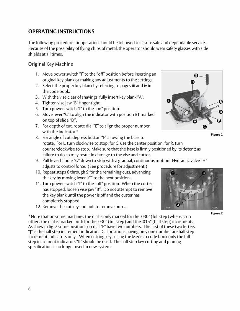
1. Move power switch “I” to the “off” position before inserting an original key blank or making any adjustments to the settings.
2. Select the proper key blank by referring to pages iii and iv in the code book.
3. With the vise clear of shavings, fully insert key blank “A”. 4. Tighten vise jaw “B” finger tight. 5. Turn power switch “I” to the “on” position. 6. Move lever “C” to align the indicator with position #1 marked
on top of slide “D”. 7. For depth of cut, rotate dial “E” to align the proper number
with the indicator.* 8. For angle of cut, depress button “F” allowing the base to
rotate. For L, turn clockwise to stop; for C, use the center position; for R, turn counterclockwise to stop. Make sure that the base is firmly positioned by its detent; as failure to do so may result in damage to the vise and cutter.
9. Pull lever handle “G” down to stop with a gradual, continuous motion. Hydraulic valve “H” adjusts to control force. (See procedure for adjustment.)
10. Repeat steps 6 through 9 for the remaining cuts, advancing the key by moving lever “C” to the next position.
11. Turn power switch “I” to the “off” position. When the cutter has stopped, loosen vise jaw “B”. Do not attempt to remove the key blank until the power is off and the cutter has completely stopped.
12. Remove the cut key and buff to remove burrs.
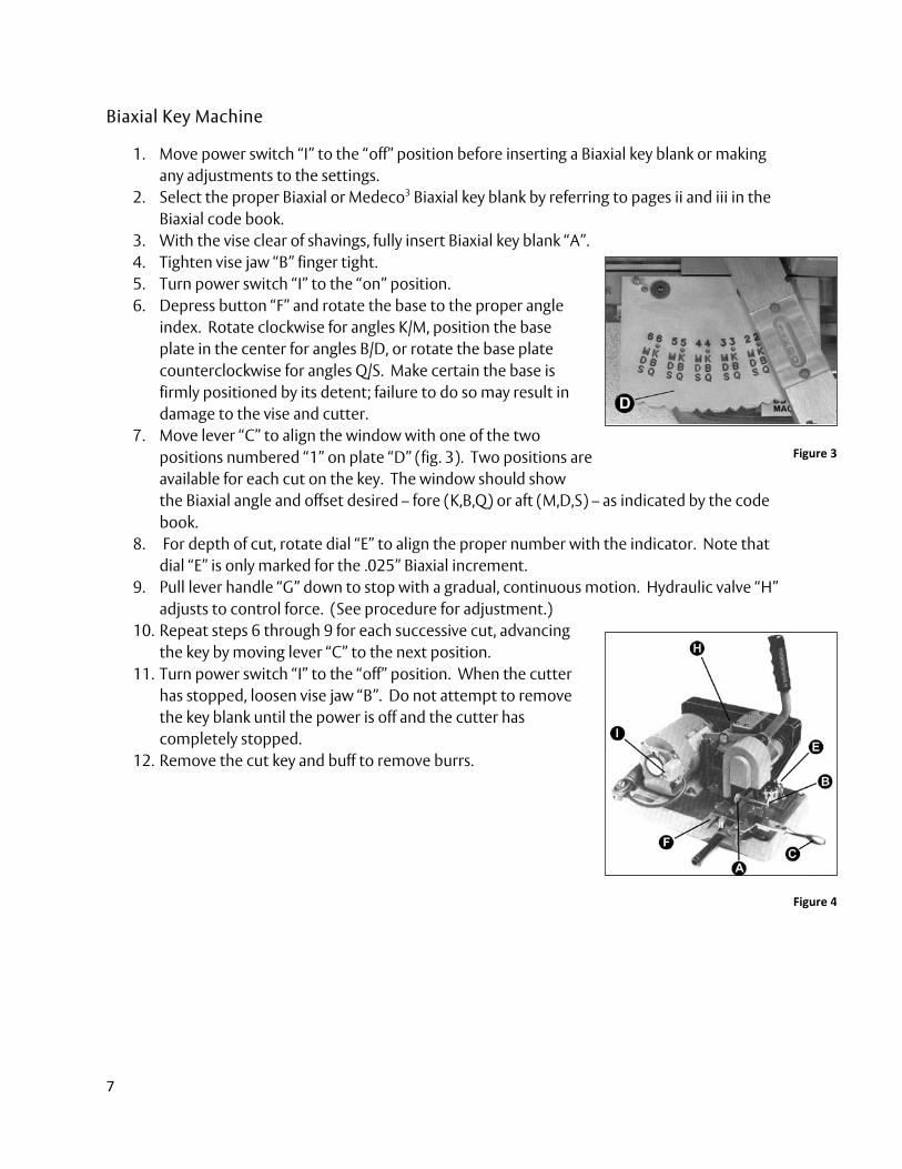
* Note that on some machines the dial is only marked for the .030” (full step) whereas on others the dial is marked both for the .030” (full step) and the .015” (half step) increments. As show in fig. 2 some positions on dial “E” have two numbers. The first of these two letters “J” is the half step increment indicator. Dial positions having only one number are half step increment indicators only. When cutting keys using the Medeco code book only the full step increment indicators “K” should be used. The half step key cutting and pinning specification is no longer used in new systems.
Figure 1
Figure 2
7
Biaxial Key Machine
1. Move power switch “I” to the “off” position before inserting a Biaxial key blank or making any adjustments to the settings.
2. Select the proper Biaxial or Medeco3 Biaxial key blank by referring to pages ii and iii in the Biaxial code book.
3. With the vise clear of shavings, fully insert Biaxial key blank “A”. 4. Tighten vise jaw “B” finger tight. 5. Turn power switch “I” to the “on” position. 6. Depress button “F” and rotate the base to the proper angle
index. Rotate clockwise for angles K/M, position the base plate in the center for angles B/D, or rotate the base plate counterclockwise for angles Q/S. Make certain the base is firmly positioned by its detent; failure to do so may result in damage to the vise and cutter.
7. Move lever “C” to align the window with one of the two positions numbered “1” on plate “D” (fig. 3). Two positions are available for each cut on the key. The window should show the Biaxial angle and offset desired – fore (K,B,Q) or aft (M,D,S) – as indicated by the code book.
8. For depth of cut, rotate dial “E” to align the proper number with the indicator. Note that dial “E” is only marked for the .025” Biaxial increment.
9. Pull lever handle “G” down to stop with a gradual, continuous motion. Hydraulic valve “H” adjusts to control force. (See procedure for adjustment.)
10. Repeat steps 6 through 9 for each successive cut, advancing the key by moving lever “C” to the next position.
11. Turn power switch “I” to the “off” position. When the cutter has stopped, loosen vise jaw “B”. Do not attempt to remove the key blank until the power is off and the cutter has completely stopped.
12. Remove the cut key and buff to remove burrs.
Figure 3
Figure 4
8
Universal Key Machine with Original Product
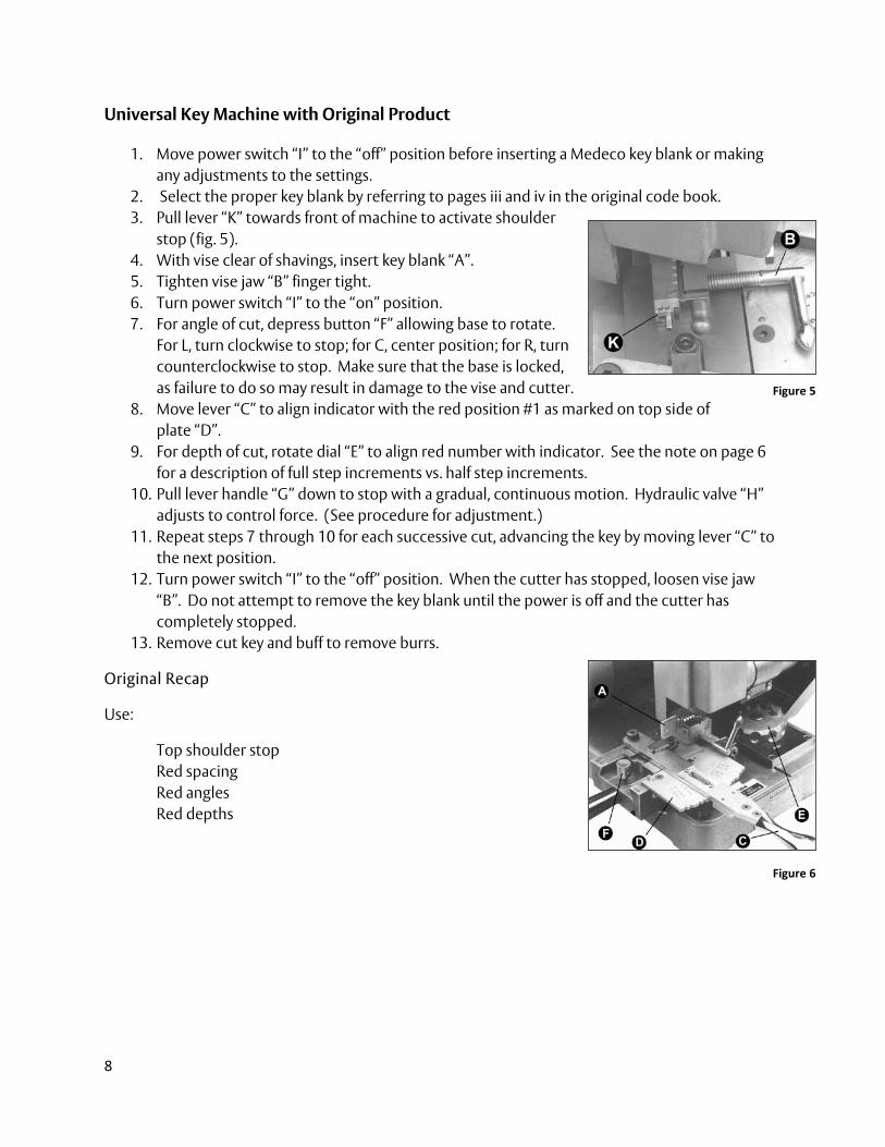
1. Move power switch “I” to the “off” position before inserting a Medeco key blank or making any adjustments to the settings.
2. Select the proper key blank by referring to pages iii and iv in the original code book. 3. Pull lever “K” towards front of machine to activate shoulder
stop (fig. 5). 4. With vise clear of shavings, insert key blank “A”. 5. Tighten vise jaw “B” finger tight. 6. Turn power switch “I” to the “on” position. 7. For angle of cut, depress button “F” allowing base to rotate.
For L, turn clockwise to stop; for C, center position; for R, turn counterclockwise to stop. Make sure that the base is locked, as failure to do so may result in damage to the vise and cutter.
8. Move lever “C” to align indicator with the red position #1 as marked on top side of plate “D”.
9. For depth of cut, rotate dial “E” to align red number with indicator. See the note on page 6 for a description of full step increments vs. half step increments.
10. Pull lever handle “G” down to stop with a gradual, continuous motion. Hydraulic valve “H” adjusts to control force. (See procedure for adjustment.)
11. Repeat steps 7 through 10 for each successive cut, advancing the key by moving lever “C” to the next position.
12. Turn power switch “I” to the “off” position. When the cutter has stopped, loosen vise jaw “B”. Do not attempt to remove the key blank until the power is off and the cutter has completely stopped.
13. Remove cut key and buff to remove burrs.
Original Recap
Use:
Top shoulder stop Red spacing Red angles Red depths
Figure 5
Figure 6
9
Universal Key Machine with Biaxial Product
1. Move power switch “I” to the “off” position before inserting a Biaxial key blank or making any adjustments to the settings.
2. Select the proper key blank by referring to pages iii and iv in the code book. 3. With vise clear of shavings, fully insert Biaxial key blank “A”. Make sure that the shoulder
stop lever “K” has been pushed back so as not to interfere with Biaxial key gauging. 4. Tighten vise jaw “B” finger tight. 5. Turn power switch “I” to the “on” position. 6. Depress button “F” and rotate base to the proper blue angle index. Rotate clockwise for
angles K/M, position the base plate in the center for angles B/D, or rotate the base plate counterclockwise for angles Q/S. Make certain the base is firmly positioned by its detent; failure to do so may result in damage to the vise and cutter.
7. Move lever “C” to align the window with one of the two positions numbered “1”. Two positions are available for each cut on the key. The window should show the blue Biaxial cut desired – fore (K,B,Q) or aft (M,D,S) – as indicated by the code book.
8. For depth of cut, rotate dial “E” to align blue Biaxial number with indicator. 9. Pull lever handle “G” down to stop with a gradual, continuous motion. Hydraulic valve “H”
adjusts to control force. (See procedure for adjustment.) 10. Repeat steps 6 through 9 for each successive cut, advancing the key by moving lever “C” to
the next position. 11. Turn power switch “I” to the “off” position. When the cutter has stopped, loosen vise jaw
“B”. Do not attempt to remove the key blank until the power is off and the cutter has completely stopped.
12. Remove cut key and buff to remove burrs.
Biaxial Recap
Use:
Bottom shoulder stop Blue spacing Blue angles Blue depths
10
KeyMark Classic Key Machine or KeyMark x4 Key Machine
1. Move power switch “I” to the “off” position before inserting a KeyMark key blank or making any adjustments to the settings.
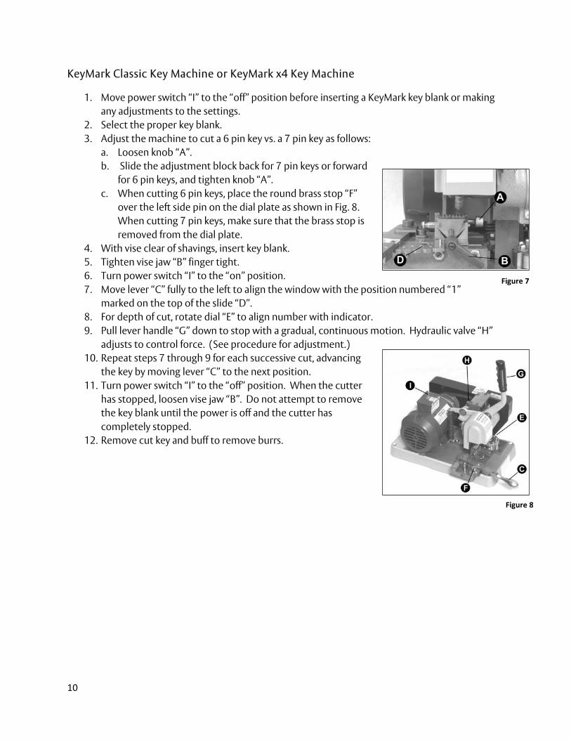
2. Select the proper key blank. 3. Adjust the machine to cut a 6 pin key vs. a 7 pin key as follows:
a. Loosen knob “A”. b. Slide the adjustment block back for 7 pin keys or forward
for 6 pin keys, and tighten knob “A”. c. When cutting 6 pin keys, place the round brass stop “F”
over the left side pin on the dial plate as shown in Fig. 8. When cutting 7 pin keys, make sure that the brass stop is removed from the dial plate.
4. With vise clear of shavings, insert key blank. 5. Tighten vise jaw “B” finger tight. 6. Turn power switch “I” to the “on” position. 7. Move lever “C” fully to the left to align the window with the position numbered “1”
marked on the top of the slide “D”. 8. For depth of cut, rotate dial “E” to align number with indicator. 9. Pull lever handle “G” down to stop with a gradual, continuous motion. Hydraulic valve “H”
adjusts to control force. (See procedure for adjustment.) 10. Repeat steps 7 through 9 for each successive cut, advancing
the key by moving lever “C” to the next position. 11. Turn power switch “I” to the “off” position. When the cutter
has stopped, loosen vise jaw “B”. Do not attempt to remove the key blank until the power is off and the cutter has completely stopped.
12. Remove cut key and buff to remove burrs.
Figure 7
Figure 8
11
Maintenance and Adjustment
To ensure uninterrupted and accurate operation of the key machine, the following adjustments and maintenance should be performed at regular intervals.
Adjusting Lever Resistance
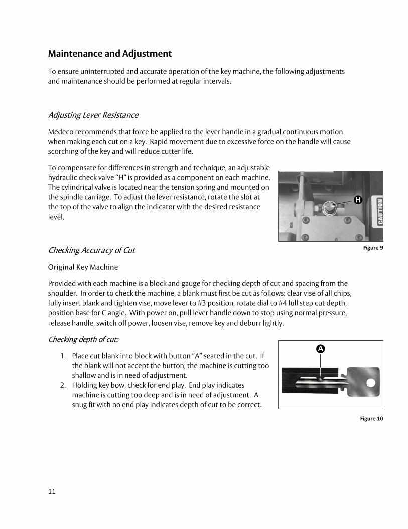
Medeco recommends that force be applied to the lever handle in a gradual continuous motion when making each cut on a key. Rapid movement due to excessive force on the handle will cause scorching of the key and will reduce cutter life.
To compensate for differences in strength and technique, an adjustable hydraulic check valve “H” is provided as a component on each machine. The cylindrical valve is located near the tension spring and mounted on the spindle carriage. To adjust the lever resistance, rotate the slot at the top of the valve to align the indicator with the desired resistance level.
Checking Accuracy of Cut
Original Key Machine
Provided with each machine is a block and gauge for checking depth of cut and spacing from the shoulder. In order to check the machine, a blank must first be cut as follows: clear vise of all chips, fully insert blank and tighten vise, move lever to #3 position, rotate dial to #4 full step cut depth, position base for C angle. With power on, pull lever handle down to stop using normal pressure, release handle, switch off power, loosen vise, remove key and deburr lightly.
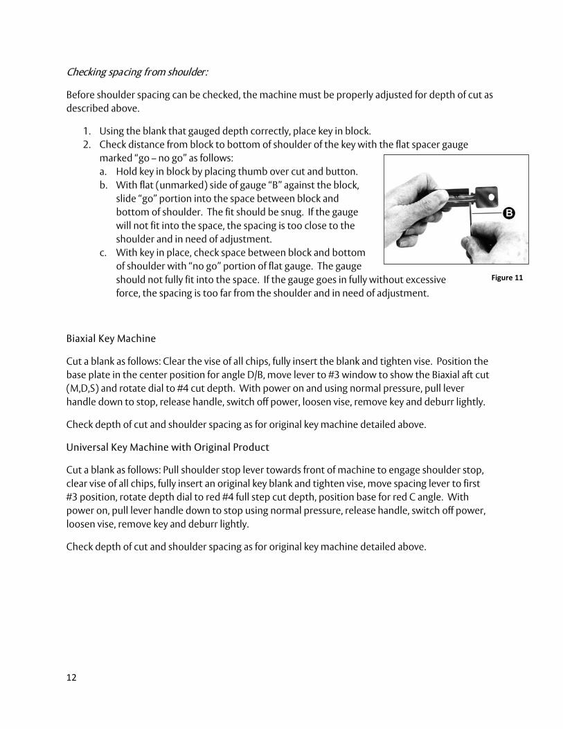
Checking depth of cut:
1. Place cut blank into block with button “A” seated in the cut. If the blank will not accept the button, the machine is cutting too shallow and is in need of adjustment.
2. Holding key bow, check for end play. End play indicates machine is cutting too deep and is in need of adjustment. A snug fit with no end play indicates depth of cut to be correct.
Figure 9
Figure 10
12
Checking spacing from shoulder:
Before shoulder spacing can be checked, the machine must be properly adjusted for depth of cut as described above.
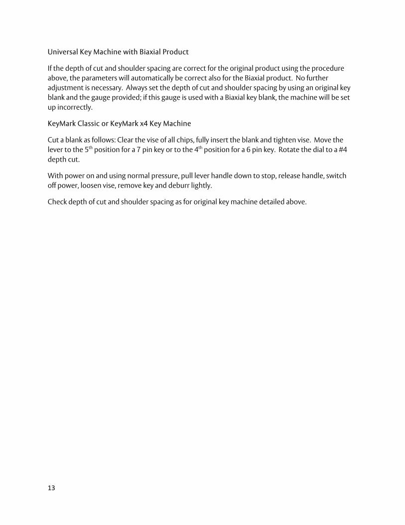
1. Using the blank that gauged depth correctly, place key in block. 2. Check distance from block to bottom of shoulder of the key with the flat spacer gauge
marked “go – no go” as follows: a. Hold key in block by placing thumb over cut and button. b. With flat (unmarked) side of gauge “B” against the block,
slide “go” portion into the space between block and bottom of shoulder. The fit should be snug. If the gauge will not fit into the space, the spacing is too close to the shoulder and in need of adjustment.
c. With key in place, check space between block and bottom of shoulder with “no go” portion of flat gauge. The gauge should not fully fit into the space. If the gauge goes in fully without excessive force, the spacing is too far from the shoulder and in need of adjustment.
Biaxial Key Machine
Cut a blank as follows: Clear the vise of all chips, fully insert the blank and tighten vise. Position the base plate in the center position for angle D/B, move lever to #3 window to show the Biaxial aft cut (M,D,S) and rotate dial to #4 cut depth. With power on and using normal pressure, pull lever handle down to stop, release handle, switch off power, loosen vise, remove key and deburr lightly.
Check depth of cut and shoulder spacing as for original key machine detailed above.
Universal Key Machine with Original Product
Cut a blank as follows: Pull shoulder stop lever towards front of machine to engage shoulder stop, clear vise of all chips, fully insert an original key blank and tighten vise, move spacing lever to first #3 position, rotate depth dial to red #4 full step cut depth, position base for red C angle. With power on, pull lever handle down to stop using normal pressure, release handle, switch off power, loosen vise, remove key and deburr lightly.
Check depth of cut and shoulder spacing as for original key machine detailed above.
Figure 11
13
Universal Key Machine with Biaxial Product
If the depth of cut and shoulder spacing are correct for the original product using the procedure above, the parameters will automatically be correct also for the Biaxial product. No further adjustment is necessary. Always set the depth of cut and shoulder spacing by using an original key blank and the gauge provided; if this gauge is used with a Biaxial key blank, the machine will be set up incorrectly.
KeyMark Classic or KeyMark x4 Key Machine
Cut a blank as follows: Clear the vise of all chips, fully insert the blank and tighten vise. Move the lever to the 5th position for a 7 pin key or to the 4th position for a 6 pin key. Rotate the dial to a #4 depth cut.
With power on and using normal pressure, pull lever handle down to stop, release handle, switch off power, loosen vise, remove key and deburr lightly.
Check depth of cut and shoulder spacing as for original key machine detailed above.
14
Adjusting Cutter
Like all mechanical devices subject to wear, the Medeco key machine will require periodic cutter adjustment or replacement. A worn cutter (indicated by incorrect measurements for the cut depth and shoulder spacing) or replacement of a cutter usually necessitates adjustment of the machine. The procedure for “checking accuracy of cut” should be followed to determine what adjustment is necessary before proceeding.
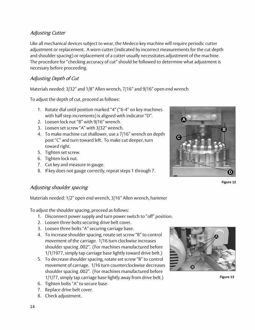
Adjusting Depth of Cut
Materials needed: 3/32” and 1/8” Allen wrench, 7/16” and 9/16” open end wrench
To adjust the depth of cut, proceed as follows:
1. Rotate dial until position marked “4” (“6-4” on key machines with half step increments) is aligned with indicator “D”.
2. Loosen lock nut “B” with 9/16” wrench. 3. Loosen set screw “A” with 3/32” wrench. 4. To make machine cut shallower, use a 7/16” wrench on depth
post “C” and turn toward left. To make cut deeper, turn toward right.
5. Tighten set screw. 6. Tighten lock nut. 7. Cut key and measure in gauge. 8. If key does not gauge correctly, repeat steps 1 through 7.
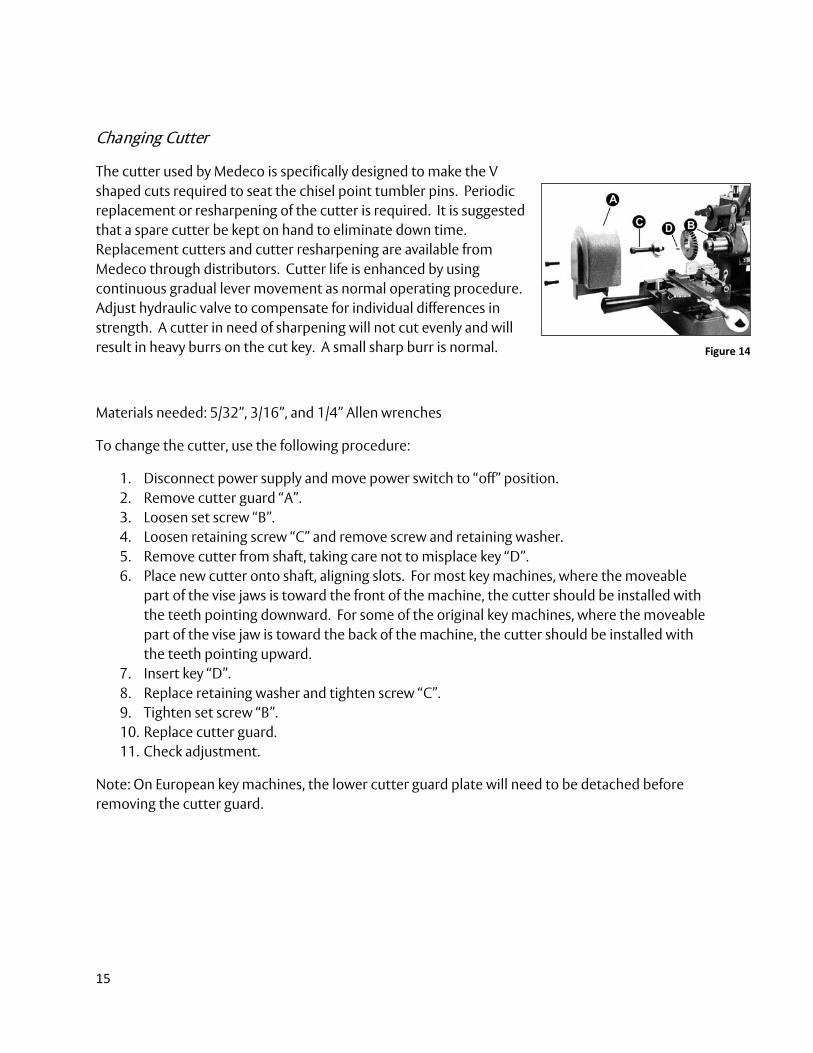
Adjusting shoulder spacing
Materials needed: 1/2” open end wrench, 3/16” Allen wrench, hammer To adjust the shoulder spacing, proceed as follows:
1. Disconnect power supply and turn power switch to “off” position. 2. Loosen three bolts securing drive belt cover. 3. Loosen three bolts “A” securing carriage base. 4. To increase shoulder spacing, rotate set screw “B” to control
movement of the carriage. 1/16 turn clockwise increases shoulder spacing .002”. (For machines manufactured before 1/1/1977, simply tap carriage base lightly toward drive belt.)
5. To decrease shoulder spacing, rotate set screw “B” to control movement of carriage. 1/16 turn counterclockwise decreases shoulder spacing .002”. (For machines manufactured before 1/1/77, simply tap carriage base lightly away from drive belt.)
6. Tighten bolts “A” to secure base. 7. Replace drive belt cover. 8. Check adjustment.
Figure 12
Figure 13
15
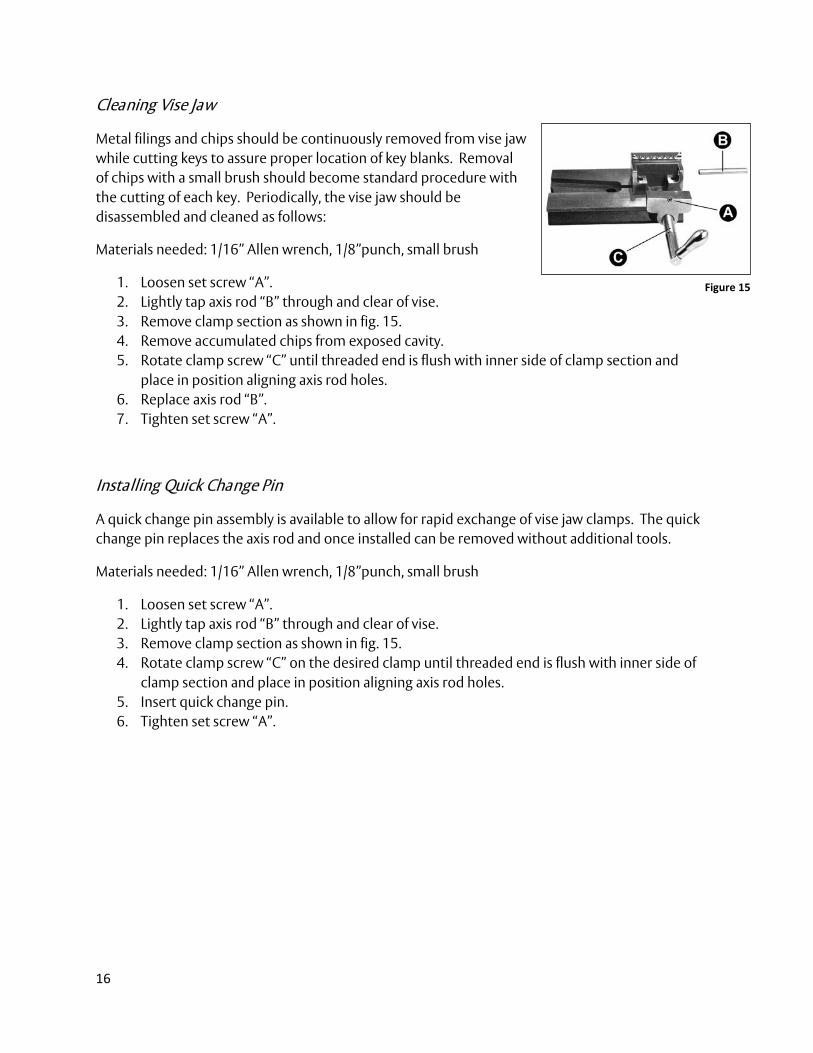
Changing Cutter
The cutter used by Medeco is specifically designed to make the V shaped cuts required to seat the chisel point tumbler pins. Periodic replacement or resharpening of the cutter is required. It is suggested that a spare cutter be kept on hand to eliminate down time. Replacement cutters and cutter resharpening are available from Medeco through distributors. Cutter life is enhanced by using continuous gradual lever movement as normal operating procedure. Adjust hydraulic valve to compensate for individual differences in strength. A cutter in need of sharpening will not cut evenly and will result in heavy burrs on the cut key. A small sharp burr is normal.
Materials needed: 5/32”, 3/16”, and 1/4” Allen wrenches
To change the cutter, use the following procedure:
1. Disconnect power supply and move power switch to “off” position. 2. Remove cutter guard “A”. 3. Loosen set screw “B”. 4. Loosen retaining screw “C” and remove screw and retaining washer. 5. Remove cutter from shaft, taking care not to misplace key “D”. 6. Place new cutter onto shaft, aligning slots. For most key machines, where the moveable
part of the vise jaws is toward the front of the machine, the cutter should be installed with the teeth pointing downward. For some of the original key machines, where the moveable part of the vise jaw is toward the back of the machine, the cutter should be installed with the teeth pointing upward.
7. Insert key “D”. 8. Replace retaining washer and tighten screw “C”. 9. Tighten set screw “B”. 10. Replace cutter guard. 11. Check adjustment.
Note: On European key machines, the lower cutter guard plate will need to be detached before removing the cutter guard.
Figure 14
16
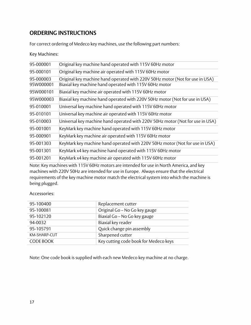
Cleaning Vise Jaw
Metal filings and chips should be continuously removed from vise jaw while cutting keys to assure proper location of key blanks. Removal of chips with a small brush should become standard procedure with the cutting of each key. Periodically, the vise jaw should be disassembled and cleaned as follows:
Materials needed: 1/16” Allen wrench, 1/8”punch, small brush
1. Loosen set screw “A”. 2. Lightly tap axis rod “B” through and clear of vise. 3. Remove clamp section as shown in fig. 15. 4. Remove accumulated chips from exposed cavity. 5. Rotate clamp screw “C” until threaded end is flush with inner side of clamp section and
place in position aligning axis rod holes. 6. Replace axis rod “B”. 7. Tighten set screw “A”.
Installing Quick Change Pin
A quick change pin assembly is available to allow for rapid exchange of vise jaw clamps. The quick change pin replaces the axis rod and once installed can be removed without additional tools.
Materials needed: 1/16” Allen wrench, 1/8”punch, small brush
1. Loosen set screw “A”. 2. Lightly tap axis rod “B” through and clear of vise. 3. Remove clamp section as shown in fig. 15. 4. Rotate clamp screw “C” on the desired clamp until threaded end is flush with inner side of
clamp section and place in position aligning axis rod holes. 5. Insert quick change pin. 6. Tighten set screw “A”.
Figure 15
17
ORDERING INSTRUCTIONS
For correct ordering of Medeco key machines, use the following part numbers:
Key Machines:
95-000001 Original key machine hand operated with 115V 60Hz motor
95-000101 Original key machine air operated with 115V 60Hz motor
95-000003 Original key machine hand operated with 220V 50Hz motor (Not for use in USA) 95W000001 Biaxial key machine hand operated with 115V 60Hz motor
95W000101 Biaxial key machine air operated with 115V 60Hz motor
95W000003 Biaxial key machine hand operated with 220V 50Hz motor (Not for use in USA)
95-010001 Universal key machine hand operated with 115V 60Hz motor
95-010101 Universal key machine air operated with 115V 60Hz motor
95-010003 Universal key machine hand operated with 220V 50Hz motor (Not for use in USA)
95-001001 KeyMark key machine hand operated with 115V 60Hz motor
95-000901 KeyMark key machine air operated with 115V 60Hz motor
95-001303 KeyMark key machine hand operated with 220V 50Hz motor (Not for use in USA)
95-001301 KeyMark x4 key machine hand operated with 115V 60Hz motor
95-001201 KeyMark x4 key machine air operated with 115V 60Hz motor
Note: Key machines with 115V 60Hz motors are intended for use in North America, and key machines with 220V 50Hz are intended for use in Europe. Always ensure that the electrical requirements of the key machine motor match the electrical system into which the machine is being plugged.
Accessories:
95-100400 Replacement cutter 95-100081 Original Go – No Go key gauge 95-102120 Biaxial Go – No Go key gauge 94-0032 Biaxial key reader 95-105791 Quick change pin assembly KM-SHARP-CUT Sharpened cutter CODE BOOK Key cutting code book for Medeco keys
Note: One code book is supplied with each new Medeco key machine at no charge.
18
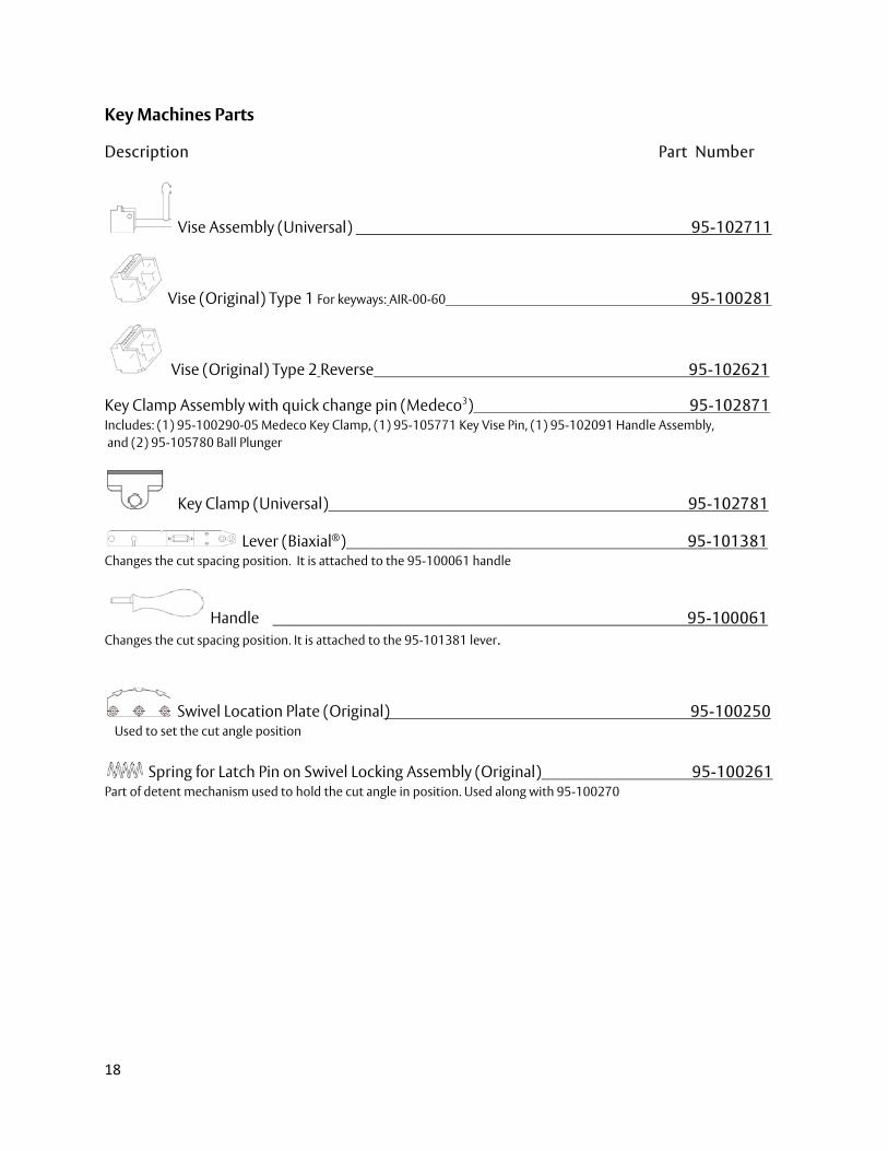
Key Machines Parts
Description Part Number
Vise Assembly (Universal) 95-102711
Vise (Original) Type 1 For keyways: AIR-00-60 95-100281
Vise (Original) Type 2 Reverse 95-102621
Key Clamp Assembly with quick change pin (Medeco3) 95-102871 Includes: (1) 95-100290-05 Medeco Key Clamp, (1) 95-105771 Key Vise Pin, (1) 95-102091 Handle Assembly, and (2) 95-105780 Ball Plunger
Key Clamp (Universal) 95-102781
Lever (Biaxial®) 95-101381 Changes the cut spacing position. It is attached to the 95-100061 handle
Handle 95-100061 Changes the cut spacing position. It is attached to the 95-101381 lever.
Swivel Location Plate (Original) 95-100250 Used to set the cut angle position
Spring for Latch Pin on Swivel Locking Assembly (Original) 95-100261 Part of detent mechanism used to hold the cut angle in position. Used along with 95-100270

Medeco Key Bitting Machine
Serial number:___________________
Year of manufacture:______________
For service and repair information contact:
Medeco U.S.: 3625 Allegheny Drive, P.O. Box 3075, Salem, Virginia 24153-0330 Customer service: 1-800-839-3157
Medeco Canada: 141 Dearborn Place, Waterloo, Ontario N2J 4N5
Customer service: 1-888-633-3264
www.medeco.com
Founded in 1968, Medeco is a market leader in locks and locking systems for security, safety, and control. The company’s customer base includes wholesale and retail security providers, original equipment
manufacturers, and institutional and industrial end users.
ASSA ABLOY is the global leader in door opening solutions, dedicated to satisfying end user needs for security, safety and convenience.
© 2011 Medeco Security Locks, Inc.