Embed Size (px)
Citation preview

Operating Instructions T161 / Servocontroller with Analog Interface +/-10 V / Ver.: Rev. c, 17.04.98 Page 1 - 1
Operating Instructions for
Servocontroller T161
with
Analog Interface +/-10 V

Page 1 - 2 Operating Instructions T161 / Servocontroller with Analog Interface +/-10 V
Version Date Author Comments Effectivity
orig. 1 July 97 SRF New edition of the formerproduct information to meetCE standards
All
Rev. a 1. Feb. 98 DRK Corrected version All
Rev. b 10. Feb. 98 DRK Further corrected version All
Rev. c 17. Apr. 98 DRK Further corrections All

Operating Instructions T161 / Servocontroller with Analog Interface +/-10 V Page 1 - 3
Contents
1. Introduction
2. System Description
3. Installation
4. Servocontroller with Analog Interface +/-10 V
5. Power Supply T160-9xx
6. Rack and Backplane
7. Servomotors
8. Maintenance and Service
Europe and Asia AmericaMOOG GmbH MOOG Inc. / NADO DivisionHanns-Klemm-Straße 28 Jamison Road71034 Böblingen EAST AURORA, NY 14052Germany U.S.A.Telephone: +0049 - 7031 - 622 - 0Fax: +0049 - 7031 - 622 -100
Telephone: +001 - 716 - 687 - 2000Fax: +001 - 716 - 687 - 4870

Page 1 - 4 Operating Instructions T161 / Servocontroller with Analog Interface +/-10 V

Operating Instructions T161 / Servocontroller with Analog Interface +/-10 V Page 1 - 5
1 IntroductionThis manual describes a system with one or more servo drives made by MOOG. The servo drive comprises abrushless AC servomotor, a servocontroller, a power supply, a backplane and a rack. The componentsdescribed operate with voltages up to 400 V. The safety instructions must be observed.
The manual is intended for the use of qualified personnel.

Page 1 - 6 Operating Instructions T161 / Servocontroller with Analog Interface +/-10 V

Operating Instructions T161 / Servocontroller with Analog Interface +/-10 V Page 1 - 7


Operating Instructions T161 / Servocontroller with Analog Interface +/-10 V / Ver.: Rev. c, 17.04.98 Page 2 - 1
2 System Description
2 System Description ........................................................................................................12.1 Components.......................................................................................................................................... 32.2 Mechanical design of the motors and servocontrollers ................................................................... 4
2.2.1 Selection of motor ........................................................................................................................... 42.2.2 Selection of control unit................................................................................................................... 5
2.3 Technical data of the system............................................................................................................... 62.3.1 Standards........................................................................................................................................ 62.3.2 Operating and ambient temperatures ............................................................................................. 6

Page 2 - 2 Operating Instructions T161 / Servocontroller with Analog Interface +/-10 V

Operating Instructions T161 / Servocontroller with Analog Interface +/-10 V Page 2 - 3
2.1 ComponentsA typical MOOG system is made up of the following components:
• Isolating transformerThe transformer serves first of all to adapt the available mains voltage to the input voltage of 3x230 VAC(3-phase operation) required by the power supply. Its second function is to ensure "safe electricalisolation" between the mains voltage and the other extra-low voltages. An autotransformer is not suitable,unless other safety precautions are also taken.
• Power supply T160-9xxThe power supply generates the DC bus voltage by rectifying and smoothing the input voltage of thepower supply. The energy generated by a rapidly decelerating servomotor is dissipated via a ballastresistor. The LED status indicator permits rapid diagnosis of any faults occurring. A relay output permitsevaluation by the host controller.
• Servocontroller T161-90xThe servocontroller electronically commutates the MOOG brushless servomotors. It closes the speedcontrol loop and delivers a 3-phase sinusoidal motor current which is controlled by a current controller withlarge bandwidth. The LED status indicator permits rapid diagnosis of faults occurring. Two relay outputspermit evaluation by the host controller.
• 19" rack with backplaneThe 19" rack accommodates the electronic components and the backplane. The latter connects the powersupply and servocontroller(s). It also provides the interfaces to the motor and for the communication withthe host controller.
• Servomotor D31x-xxx / G4xx-xxxThe standard MOOG brushless servomotor comprises a wound stator, a rotor with permanent magnets(cobalt-samarium), a 2-pole resolver and a NTC thermistor embedded in the end turns of the stator.
L1
L2
L3
PE M,N
Resolver
NS
MOOGIsolatingtransformer
Powersupply
Additionalservocontrollers
Moog
servocontrollerbrushless
servomotor
Setpointsignal
Fig. 2.1: Typical MOOG servosystem

Page 2 - 4 Operating Instructions T161 / Servocontroller with Analog Interface +/-10 V
2.2 Mechanical design of the motors and servocontrollers
2.2.1 Selection of motor
a) The motor type is predetermined by parameters M0, Mmax, nmax, s1 characteristic in motor catalogue
--> Determination of kt.
b) Application specific are required (torque characteristic MA(t), working cycle)
--> Determination of cycle time tC, time intervals ti, torque values M
i, Mmax
Motor type G4xx-xxx with kt.
M n M nA A A,max ,max max ,max( ) ( )≤ ?
YES NO
Calculation of the effective torque
MM t
teff
i ii
C
=×∑ 2
Calculation of the mean speed nm
Motorunsuitablefor thisapplication.
Does Meff (nm) lie inside the s1 curve?
YES NO
Motor selection complete. Motor unsuitable for thisapplication.
Fig. 2.2: Selection of motor

Operating Instructions T161 / Servocontroller with Analog Interface +/-10 V Page 2 - 5
2.2.2 Selection of control unit
Motor type selected: G4xx-xxx (kt from motor catalogue). Known torquecharacteristic for the application: ---> Peak torque for the application MA,max.Calculation of the maximum current for the application
IM
kAA
t,max
,max=
The maximum servocontroller current IC,max and continuous current IC,m can befound in chapter 4.I IA C,max ,max≤ ?
YES NOCalculation of the mean current IA,m for the application from themean torque MA,m of the application
MM t
tA m
i ii
C, =
×∑
IM
kA mA m
t,
,=×η
with η = 0.85 .. 0.9 due to saturation of the kt curve
Servo-controllerunsuitablefor thisapplication.
Repeatprocedurewith the nextlarger servo-controller.
I IA m C m, ,≤ ?
YES NO
Check motor / servocontroller combinationwith reference to chapter 4 (paragraph"Setting the MCO jumper L401")
Servo-controllerunsuitablefor thisapplication.
Is a corresponding jumper position listed?Repeatprocedurewith next
YES NOlarger servo-controller.
Position jumper.Selection of theservocontroller iscomplete.
Motor / servocontrollercombination not suit-able for this appli-cation
Fig. 2.3: Selection of servocontroller

Page 2 - 6 Operating Instructions T161 / Servocontroller with Analog Interface +/-10 V
2.3 Technical data of the system
2.3.1 StandardsDIN VDE 0160 has been taken into account to a particularly strong extent in the development of theseproducts.The following standards have been taken into account:
Guidelines for engineering design DIN VDE 0160 prEN 50178Dimensioning of creepage distances and clearances VDE 0110 Part 2Insulation coordination VDE 0110 Part 1 IEC 664General safety requirements DIN VDE 0160 prEN 50178Reliable isolation DIN VDE 0160 prEN 50178Marking DIN VDE 0160 prEN 50178Grounding DIN VDE 0160 prEN 50178Overvoltage protection DIN VDE 0160 prEN 50178Ambient conditions IEC 68 Part 2-3, 2-6Short-circuit strength DIN VDE 0160 prEN 50178Mechanical stresses IEC 68 Part 2-29Protection by limitation of discharge energy DIN VDE 0160 prEN 50178Type-testing DIN VDE 0160 prEN 50178EMC* VDE 0871
EN 55011EN 50082-1
CISPR22
* The MOOG control units series T161 can only conform to the above EMC guidelines if the MOOG EMCinstallation guidelines are considered and an input filter in the supply voltage lines is installed.
2.3.2 Operating and ambient temperaturesElectronic components:
Temperature for transport and storage: -25 °C to 70 °COperating temperature: 0 °C to 55 °CHumidity: 5 % to 85 %, 1 g/m3 to 25 g/m3,
in accordance with prEN50178 class 3k3Type of protection: Components must be installed into an enclosed rack.
The enclosed rack must provide at least IP54 per standardEN60529.
Ventilation: See component specification.Installed position: Only vertical.Overvoltage protection class: Category 2 per standard VDE0110 / IEC664Noise: The noise depends on the user selected fan and cabinet.
The electronic components do not make noise.
Servomotors and cables:
See Chapter "7 Servomotors"

Operating Instructions T161 / Servocontroller with Analog Interface +/-10 V / Ver.: Rev. c, 17.04.98 Page 3 - 7
3 Installation
3 Installation .......................................................................................................................73.1 Safety Instructions................................................................................................................................ 2
3.1.1 Explanation of Symbols used.......................................................................................................... 23.1.2 Qualified personnel ......................................................................................................................... 33.1.3 Intended use ................................................................................................................................... 33.1.4 List of main safety instructions........................................................................................................ 3
3.2 Information on EMC.............................................................................................................................. 53.3 Installation procedure .......................................................................................................................... 63.4 Disassembly procedure ....................................................................................................................... 73.5 Overview of the overall system ........................................................................................................... 83.6 Minimum wiring of the backplane ....................................................................................................... 93.7 Installing and wiring of the power supply........................................................................................ 10
3.7.1 Check name plate ......................................................................................................................... 113.7.2 Power supply connections ............................................................................................................ 123.7.3 External 24 VDC supply for power supply unit (optional).............................................................. 133.7.4 Power connection ......................................................................................................................... 143.7.5 Configuring the power supply unit for ballast resistance............................................................... 17
3.8 Connecting the servomotors............................................................................................................. 193.9 Wiring the servocontroller inputs and outputs................................................................................ 22


Operating Instructions T161 / Servocontroller with Analog Interface +/-10 V Page 3 - 1

Page 3 - 2 Operating Instructions T161 / Servocontroller with Analog Interface +/-10 V
3.1 Safety Instructions
3.1.1 Explanation of Symbols used
Important!The symbol on the left and the word "Important" are used to draw attention to safetyinstructions concerning a potential hazard for persons.Failure to comply with these safety instructions can result in serious damage to health andcan even prove fatal in extreme cases.These safety instructions must be observed without fail.
+Warning:The symbol on the left and the word "Warning!" are used to draw attention to instructionsconcerning potential damage to the servo drive or to the system as a whole.Such warnings must be observed without fail.
+Note:Notes contain useful information for the operator when starting up and operating the system.
Danger - High voltage (Sticker on the power supply and servomotor)The symbol on the left indicates that the power supply operates with high voltages which canprove extremely dangerous if touched.
Beware of hot parts (Sticker on servomotor)In extreme applications, the surface of the servomotor may heat up to more than 100 °C andcan cause skin burns if touched. The servomotor must therefore be protected to preventcontact.
Delicate part (Sticker on servomotor)A hammer must not be used to force the gearing / gear wheel onto the shaft when installingsuch parts. The screw thread in the center of the shaft must be used for this purpose. Anextractor supported on the center of the shaft must be used when dismantling the parts.

Operating Instructions T161 / Servocontroller with Analog Interface +/-10 V Page 3 - 3
3.1.2 Qualified personnel
Important!The components making up the drive system may only be installed and serviced by dulyqualified personnel. The accident prevention regulations (UVV) and particularly VGB 4 andVGB 5 must be taken into account, as must the following VDE safety standards: VDE 100,VDE 105, DIN EN 60204 and prEN 50178.
Unqualified work on the drive components and failure to comply with the warnings contained in this manual oraffixed to the components can result in serious physical injury or damage to property.
The work permitted within the scope of this manual may consequently only be undertaken by duly qualifiedpersonnel.
This includes the following people:
• planning and engineering design personnel familiar with the safety guidelines for measurement andcontrol instrumentation,
• operating personnel who have been duly instructed with regard to the handling of measurement andcontrol instrumentation and who are familiar with the operating instructions contained in this manual,
• commissioning and service personnel authorized to start up, ground and mark the circuits forcomponents and systems in accordance with safety engineering standards.
3.1.3 Intended useThe drive components have been developed and built for installation and operation in industrial systems.
The electronic components (power supply, servocontroller, backplane) are designed for installation in a rack.These electronic components do not have a separate housing and are therefore not protected againstaccidental contact. It is therefore absolutely essential that they be installed in a rack. The rack mustadditionally be installed in a closed control cabinet.
Protection against accidental contact must be ensured by installation.
3.1.4 List of main safety instructions
Danger - High voltage!The servo drives operate with potentially lethal voltages.The servocontroller and power supply are individual components and designed forinstallation in a rack in a control cabinet. The individual components do not have a separatehousing and are therefore not protected against accidental contact with high voltages.
For this reason:
• A rack must be used The components must be installed in a rack before being put into operation. The rack must
ensure complete protection against accidental contact. If not all the slots in the rack areused, the unused slots must be covered by filler panels.
• Install the rack in a control cabinet High voltages flow through the backplane, which must consequently be protected against
accidental contact. The rack must therefore be installed in a control cabinet.

Page 3 - 4 Operating Instructions T161 / Servocontroller with Analog Interface +/-10 V
Danger - High voltage!The servo drives operate with potentially lethal voltages.
For this reason:
• Disconnect the system from the mains supply.Before starting any work on the drive system, it must be disconnected from the powersupply and secured against inadvertent reconnection by means of the master switch.
• The servomotors must come to a complete stop.Rotating servomotors can generate potentially lethal voltages by acting as generators.
Beware of charged capacitors!The capacitors in the power supply may still be charged.
For this reason:
• Note the discharge time of the capacitors.The power supply contains capacitors which may be charged with up to 400 VDC. Wait atleast 5 minutes for the capacitors to become discharged after disconnecting the voltage.
• The voltage must then be measured between DC+ (X7/1) and DC- (X7/2).Work on the power supply must not start until the voltage has dropped below 5 V.
Beware of mechanical hazards!Servomotors can accelerate highly dynamically. They also have an enormous torque. Thefollowing points must therefore be observed when starting the system.
• The danger zone of the motor must be cordoned off.The system must feature a guard door preventing personnel from reaching into orentering the danger zone. If the guard door is opened, the drive system must bedisconnected from the supply voltage immediately.
• The motor may accelerate inadvertently on account of wiring faults or errors in theapplication software. Appropriate safety precautions must therefore be taken in thesystem to ensure that neither personnel nor machine components are endangered in anyway.
Danger - High voltage on backplane!High voltages flow through the backplane, as well as through some screw terminals and thesoldering pins.
For this reason:
• Before starting any work on the backplane, the system must be disconnected from thepower supply and secured against inadvertent reconnection by means of the masterswitch.

Operating Instructions T161 / Servocontroller with Analog Interface +/-10 V Page 3 - 5
3.2 Information on EMC(Only applies for countries in the European Community)
+Exclusion of liability
The information on EMC provided here contains general recommendations to assist themanufacturer when installing RMC components made by MOOG in finished products whichmust conform to the requirements of EC Directive 89/336/EEC (EMC Directive). AlthoughMOOG has exercised utmost care in compiling these recommendations, we cannot acceptany liability whatsoever for claims associated with the user’s individual applications. This alsoapplies in particular with regard to non-performance, non-compliance, faults,misunderstandings and mistaken interpretation.
+Note:
Responsibility for ensuring that every finished product containing these componentsconforms to the requirements of the EMC Directive rests entirely with the manufacturer ofthe finished product. MOOG cannot accept any liability whatsoever for finished productsmade by other manufacturers and containing 19" RMC components from MOOG.
EMC environment
The 19" RMC components from MOOG are designed for installation in industrial equipment and for operationin industrial areas. The 19" RMC components from MOOG have therefore been tested in accordance with thefollowing EMC standards:
EN55011: Limit values and methods of measuring the radio interference of industrial, scientific and medicalhigh-frequency equipment (ISM devices) (1991), class A limit values.
EN50082-2: Elektromagnetic compatibility (EMC)Basic standard on immunity to interferencePart 2: Industry (1995).
Installation of the components
The 19" RMC components from MOOG are designed for installation in an assembly comprising a rack, fanand backplane which must in turn be installed in a control cabinet or housing. For the sake of simplicity, theassembly comprising the rack, fan and backplane will henceforth simply be referred to as the rack. Thecontrol cabinet or housing will be referred to as a control cabinet. Rack and control cabinet must be providedby the manufacturer of the finished product.
The rack used must have been developed or modified for optimized EMC grounding and shielding (e.g.Schroff Europac Lab HF Subrack, see order information). All 19" RMC components or modules from MOOGmust be firmly installed in the rack. All screw connections must be tightly secured.
All metal covers (filler panels, side panels, covers, etc.) belonging to the rack must be fitted and a continuousground connection guaranteed between all panels. All ground connections between the rack and the controlcabinet must be securely mounted and a continuous ground connection guaranteed.
To ensure an optimum EMC shield, the control cabinet should have a continuous ground connection betweenall metal panels (frame, side panels, top, baseplate, etc.). A control cabinet which has been designed toprovide an optimum EMC shield can be used for this purpose.
The manufacturer of the finished product must take into account the effects of additional interference due toother modules, systems or power supplies installed in the finished product, as well as the interaction betweenactual and potential sources of interference in the finished product. The manufacturer of the finished productis responsible for taking suitable precautions to minimize such interference in the finished product, forexample by maintaining a safe distance between such parts or shielding them inside the product. He mustdecide which is the most efficient method in every single finished product.

Page 3 - 6 Operating Instructions T161 / Servocontroller with Analog Interface +/-10 V
Where possible, shielded cables with fully shielded connector housings should always be used. The cableshield must be connected to the connector shields over the full 360° in order to ensure a continuous all-roundground connection. All cable connections to the backplane must be tightly secured. In particular, all screws inthe ground connections of the connector shields must be securely tightened. Cables must be routed as farapart as possible to avoid interference in the control cabinet. If cables must be crossed, they should do so atan angle of 90°. This reduces the interference to a minimum. Here too, the manufacturer of the finishedproduct must decide which is the most efficient method for each individual product.
Further details on filtering, grounding and shielding can be found in this manual.
3.3 Installation procedureThis chapter on installation refers to all servocontrollers in series T161 and is therefore very general. Theservocontrollers T161 are available with different software versions and different functions. Three versions arecurrently available:
1. Servocontroller with analog setpoint for speed or torqueThis constitutes the basic version. The higher-ranking positioning control specifies a speed for theservocontroller via an analog signal (-10 V .. +10 V). The drive reports its actual position to the control viaan encoder simulation (simulation of an incremental encoder).
2. Servocontroller with connection to the CAN bus and Interpolation Mode protocolIn this version, the control system specifies setpoint positions for the servocontroller at fixed intervals(every 6 .. 64 milliseconds) via the CAN bus. The servocontroller interpolates between the individualsetpoint positions and follows the specified path.Extensive status messages are output to the control system and make troubleshooting easier. The systemis fully digital and thus insusceptible to external disturbances and drift.
3. Servocontroller with connection to the CAN bus and Profile Mode protocolIn this version, the control system only sends short commands to the servocontroller via the CAN bus.These commands are evaluated by the servocontroller and executed without further assistance by thecontrol system. Positioning is achieved through specification of the target position, max. speed and max.acceleration. The servocontroller generates its own path and reports to the control system when it reachesthe target position. Other functions are also available, such as electrical gearing, cam functions, etc.Extensive status messages are output to the control system and make troubleshooting easier. The systemis fully digital and thus insusceptible to faults and drift.
Servocontroller versions with different functions ⇒ different wiringThe servocontroller versions with different functions also require different wiring, since the inputs and outputsare differently defined by software.Attention is therefore drawn to the appropriate servocontroller chapter during the installation procedure.

Operating Instructions T161 / Servocontroller with Analog Interface +/-10 V Page 3 - 7
3.4 Disassembly procedureThe servodrives described here operate with voltages which can cause serious damage to health if touched.The following safety instructions must therefore be observed when dismantling the drives and also whenmaking minor changes to the wiring.
Danger - High voltage!The servo drives operate with potentially lethal voltages.
For this reason:
• Disconnect the system from the mains supply.Before starting any work on the drive system, it must be disconnected from the powersupply and secured against inadvertent reconnection by means of the master switch.
• The servomotors must come to a complete stop.Rotating servomotors can generate potentially lethal voltages by acting as generators.
Beware of charged capacitors!The capacitors in the power supply may still be charged.
For this reason:
• Note the discharge time of the capacitors.The power supply contains capacitors which may be charged with up to 400 VDC. Wait atleast 5 minutes for the capacitors to become discharged after disconnecting the systemfrom the mains.
• The voltage must then be measured between DC+ (X7/1) and DC- (X7/2).Work on the power supply must not start until the voltage has dropped below 5 V.
Danger - High voltage on backplane!High voltages are present at the backplane, as well as through some screw terminals andthe soldering pins.
For this reason:
• Before starting any work on the backplane, the system must be disconnected from themains voltage and secured against inadvertent reconnection by means of the masterswitch.

Page 3 - 8 Operating Instructions T161 / Servocontroller with Analog Interface +/-10 V
3.5 Overview of the overall system
12
3
4
PSUA
B
DC
FE
Fig. 3.1: Rack with 6 axes
1. Power supply unit (PSU)
2. Servocontroller (6 controllers, A to F)
3. Rack (19 inch)
4. Fan
S e r v o c o n t r o l le r T 1 6 1 -9 . . .
A u to m a t icc i r c u i t-b re a k e r
P o w e r s u p p ly T 1 6 0 -9 .. .
P E
P E X 3
2
3
4
1
5
M a in s f i l te r
C o n ta c to r
2 4 V
X 5
5
6
P S U re a d y
re la y
S ig n a lP o w e r
c a b le c a b le
R S -2 3 2
D C b u s
+ / -1 5 V , 5 V
S e rv o c o n t ro l le rT 1 6 1 -9 . . .
B ru s h le s s s e rv o m o to r
E x te rn a lb a lla s tre s is ta n c e(o p t io n a l)
C o n t ro l /
P o s it io n in g c o n t ro l
S e tp o in ts
E n a b le
X 6
B +
W
B -P EP E
UV
X A 4
X A 6
X 6
B +
W
B -P EP E
UV
X B 4
X B 6
3 /P E A C 4 0 0 V
tra n s fo rm e rIs o la t in g
L 1
L 2
L 3
M a s te r s w itc h
3 A C 2 3 0 V
E m e rg e n c y o f f
Fig. 3.2: Overall system
Operating Instructions T161 / Servocontroller with Analog Interface +/-10 V Page 3 - 9
3.6 Minimum wiring of the backplane
Fig. 3.3: Minimum wiring (① Only for servocontrollers with analog setpoint specification)

Page 3 - 10 Operating Instructions T161 / Servocontroller with Analog Interface +/-10 V
3.7 Installing and wiring of the power supply
Danger - High voltage!The servo drives operate with potentially lethal voltages.
For this reason:
• Disconnect the system from the mains supply.Before starting any work on the drive system, it must be disconnected from the powersupply and secured against inadvertent reconnection by means of the master switch.
• The servomotors must come to a complete stop.Rotating servomotors can generate potentially lethal voltages by acting as generators.
Beware of charged capacitors!The capacitors in the power supply may still be charged.
• Note the discharge time of the capacitors.The power supply contains capacitors which may be charged with up to 400 VDC. Wait atleast 5 minutes for the capacitors to become discharged after disconnecting the systemfrom the mains.
• The voltage must then be measured between DC+ (X7/1) and DC- (X7/2).Work on the power supply must not start until the voltage has dropped below 5 V.
+Warning:A fan is required if more than four servocontrollers are installed.Then the fans must be switched on as soon as voltage is applied to the power supply.If the power supply requires an external 24 VDC supply, the fan must be switched on assoon as the 24 VDC supply is connected.
Five points must be noted in addition to the safety instructions when carrying out this work:
1. Does the power supply unit require an external 24 VDC supply?
2. Is the power supply unit operated with one or three phases?
3. Which ballast circuit is planned?
4. Does the power supply unit require a fan?
5. Install a mains filter (EMC precaution).

Operating Instructions T161 / Servocontroller with Analog Interface +/-10 V Page 3 - 11
3.7.1 Check name plate
MOOG Ltd. Made in Ireland
Model:
SerNo:
7���������������
7����
MOOG Ltd. Made in Ireland
Model:
SerNo:
7���������������
7����
MOOG Ltd. Made in Ireland
Model:
SerNo:
7���������������
7����
# indicates the Revision Index.This manual applies for all revisions.
SerNo: T0123 indicates the serial number.The serial number is incremented with every part produced.
+The name plate serves to identify the product.For this reason:
• Check whether the name plate on the device matches the name plate illustrated above.
• This documentation must not be used for commissioning and startup if the name platesdo not match.
• Devices without name plate are not covered by the manufacturer’s warranty and must notbe put into operation.

Page 3 - 12 Operating Instructions T161 / Servocontroller with Analog Interface +/-10 V
3.7.2 Power supply connections
;�
;�
;�
;�
;$�
;$�
;$�
;$�
;�
Abb 3.4: Backplane (power supply slot)
X3 Power connectionLeads with up to 3 mm²Pin 1 PEPin 2 L1, 230 VACPin 3 L2, 230 VACPin 4 L3, 230 VACPin 5 PE
X4 Ballast connectionLeads with up to 3 mm²Pin 1 Ballast resistancePin 2 Ballast resistancePin 3 PEPin 4 Not used
X7 DC bus connectionLeads with up to 3 mm²Pin 1 DC+Pin 2 DC-Pin 3 PE
X5 Miscellaneous connectionsLeads with up to 1.5 mm²Pin 1 Power supply for brake, +24 VDCPin 2 Reference ground for pin 1Pin 3 +24 VDC (optional supply for PSU)Pin 4 Reference ground for pin 3Pin 5 "PSU ready" output, 1st relay contactPin 6 "PSU ready" output, 2nd relay contactPin 7 PEPin 8 +5 V, Test outputPin 9 +15 V, Test outputPin 10 -15 V, Test outputPin 11 AGND, reference ground to pin 9 and 10Pin 12 DGND, reference ground to pin 8Pin 13 "System ready relay" output,
1st relay contactPin 14 "System ready relay" output,
2nd relay contactPin 15 Digital input for servocontroller
(function depends on servocontroller and backplane type),Ref.: ExtIO_GND of servocontroller (Xµ5/14)
Terminal types for X3, X4 and X7Type: Phoenix GSMKDS3 (angled screw terminal)Wire cross-sectional area: max. 3 mm2, min. 2.5 mm2
Terminal type for X5Type: Phoenix SMKDS1.5 (angled screw terminal)Wire cross-sectional area: max. 1.5 mm2
Operating Instructions T161 / Servocontroller with Analog Interface +/-10 V Page 3 - 13
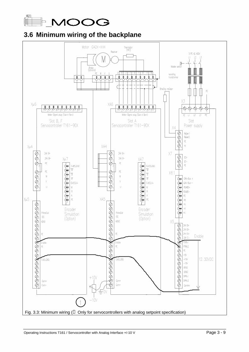
3.7.3 External 24 VDC supply for power supply unit (optional)1. Power supply unit T160 - 901 # - 00 - 1#
This power supply unit does not require an external 24 VDC supply.
2. Power supply unit T160 - 902 # - 00 - 1#Power supply unit T160 - 932 # - 00 - 1#These two power supply units require an external 24 VDC supply. The voltage is connected to terminalX5-pin 3 (positive) and terminal X5-pin 4 (negative).
3. The +5 V and ±15 V are generated from this 24 VDC supply. This ensures that the microcomputer, theposition measurement and an optional CAN bus remain fully functional if the power has to bedisconnected for operational reasons, e.g. following an Emergency SWITCH OFF.
Important: A 24 VDC supply with reliable insulation must beused!The power supply providing the 24 VDC for the MOOG power supply unit must be reliablyinsulated from the mains voltage and must conform to standard EN 60950.
+h EMC recommendation:The connecting leads must be routed through a ferrite core in order to filter out theconducted DC interference. The ferrite core must be positioned as close to the power supplyunit as possible so that the connection between core and terminal is as short as possible.It must be ensured that both leads are routed in parallel. They must both be inserted into thehole of the core in the same direction and both leads must have the same number of turns(four turns) (see figure below).
Ferrite Absorber (ferrite core)
24 V +
24 V -
24 V + -> Power Supply
24 V - -> Power Supply
30 µH+
-
Fig. 3.5: Ferrite core on the 24 V input (signal voltage)

Page 3 - 14 Operating Instructions T161 / Servocontroller with Analog Interface +/-10 V
3.7.4 Power connection
The power supply unit can be operated with either a one-phase or three-phase AC voltage:
Minimum Nominal Maximum
Supply voltage 207 VAC 230 VAC 254 VAC
Mains frequency 44 Hz 50 Hz 66 Hz
Fuse 16 A slow-blow *)
*) A 3-phase automatic circuit-breaker must be used for 3-phase operation in order to ensure that allphases are tripped at the same time in the event of a fault!
Important: Isolating transformer requiredThe isolating transformer is required in order to maintain the specified isolation (creepagedistances and clearances) in relation to unprotected small-signal auxiliary voltages. Theisolating transformer must conform to standard EN 60204-1. The protective earth conductormust be connected.
If other precautions are taken,- the power supply unit can be connected directly to the mains supply for one-phase
operation,- an autotransformer can be used to adjust the voltage for three-phase operation.
One-phase operation:
In one-phase operation, the voltage between live and neutral is 230 VAC. An isolating transformer with 1:1transformation ratio must be used. The secondary terminals of the isolating transformer are connected toterminal X3-pin 2 and X3-pin 3. The protective earth conductor must also be connected.
Three-phase operation:
The nominal voltage between the power supply unit terminals must be equal to 230 VAC. The phase-to-phase voltage of a normal 3x400 VAC 3-phase mains supply must be stepped down to 3x230 VAC by meansof an isolating transformer connected to terminal X3. The protective earth conductor must be connected.
+Note:
Leakage currents flow on the PE conductor if no isolating transformer is used.The leakage current may exceed 3.5 mA under corresponding operating conditions. It istherefore recommended to connect an additional PE conductor of at least 10 mm2 to the rack(see VDE 0160).
The leakage currents are drastically reduced when using an isolating transformer.

Operating Instructions T161 / Servocontroller with Analog Interface +/-10 V Page 3 - 15
3.7.4.1 Configuring the power supply for 1-phase or 3-phase operationJumper JW1 must be reconnected for this purpose (see figure 3.8):
Mode of operation Position of jumper JW 1
1-phase On the mark 1 φ3-phase On the mark 3 φ
If one phase fails in 3-phase operation, the "power supply ready" relay in the power supply unit opens and thefault is indicated. The red LED 3∼ lights up on the front panel. The power supply unit remains operationalhowever. Since the current is no longer distributed over all three phases following a phase failure, the powersupply unit may heat up when high power levels are output. The connected servocontrollers are disabled viaan internal fault signal when the temperature limit is reached.
3.7.4.2 Important information
+Warning: Note the switch-on sequence!
• Switching onIf the power supply unit has an external 24 VDC supply, the 24 VDC must be switched onfirst. The power can be switched on after a delay of 2 seconds.
• Switching offEither the power can be switched off first and then the 24 VDC supply or the power and24 VDC supply can be switched off at the same time (e.g. via the master switch on themachine).
If the 24 VDC supply is switched off but the power remains on due to a fault, the power mustbe switched off by hand. Wait at least 5 minutes before switching the power supply uniton again.
• Short time disconnection of the powerIf the power is only to be disconnected for a short time, a delay of at least 2 seconds mustbe allowed before reconnecting the power.
+Warning: Note the softstart!
• Inrush current limitation(= softstart)The power supply unit is protected by an inrush current limitation. The DC bus capacitorsare charged via a resistance which is bridged upon expiration of the charging time(1 second).
• None of the servocontrollers must be enabled while the softstart is active, otherwise thecharging current will flow into the motor instead of the capacitors, causing the softstart tohave no effect. The fuse before the power supply unit will be tripped by the high switch-oncurrent in this case.
• "PSU ready" relay (terminals X5/5 and X5/6)The relay contact is closed as soon as the softstart procedure is complete and the powersupply unit is ready to supply the servocontrollers with power. The relay contact isopened in the event of a fault.
+Note:
MOOG recommends the circuit illustrated in Fig. 3.6 to be used.

Page 3 - 16 Operating Instructions T161 / Servocontroller with Analog Interface +/-10 V
ContactorEmergency OFF
Power supply unit T160-9xx
Host Controller
X3
2
3
4
1
X5
5
PE
PE
5
6
Power on/off
Enable
24 V
&
XA5-10, XB5-10, etc
Enable
PSU readyrelay
Mains filter
for servocontrollers
Automaticcircuit-breaker
3/PE AC 400 V
transformerIsolating
L1
L2
L3
Master switch
3/AC 230 V
Fig. 3.6: Wiring of the power supply unit
Important: Emergency OFF buttons must be usedThe Directive concerning the safety of machines specifies that an Emergency OFF switchmust be installed in the system so that the servo drives can be disconnected from the mainsvoltage in an emergency.
+h EMC recommendation:The connecting leads must be routed through a ferrite core in order to filter out theconducted DC interference. The ferrite core must be positioned as close to the power supplyunit as possible so that the connection between core and terminal is as short as possible.It must be ensured that all three leads are routed in parallel. They must all be inserted intothe hole of the core in the same direction and must all have the same number of turns (seediagram below).
X3
2
3
4
1
5
38 µΗ30 µΗ
Mains filter
L1
L2
L3
PE
L3’
L1 L1’
L2’L2
L3
Wiring principle
4 turns
L1
L2
L3
PE
PE
Powersupplyunit
L3’
L1 L1’
L2’L2
L3
Wiring principle
5 turns
Fig. 3.7: Power connection with mains filter and ferrite core

Operating Instructions T161 / Servocontroller with Analog Interface +/-10 V Page 3 - 17
3.7.5 Configuring the power supply unit for ballast resistanceThe following notes must be observed without fail when using an external ballast resistance:
Danger - High voltage!Voltages of up to 400 VDC may be present at the external ballast resistance. It musttherefore be protected against accidental contact.Recommendation: cover with a perforated metal sheet.EN 60204 "Safety of electrical machines" requires that the housing of a ballast resistancemust be according to at least IP22.
Danger - High temperatures!The ballast resistance can become very hot during operation. It must therefore be installedso that its high temperature does not constitute a source of danger. The cover (perforatedmetal sheet) may also become very hot and must therefore be protected against accidentalcontact.
+h EMC recommendation:The ballast resistance should be installed in a perforated case to protect it against accidentalcontact. The perforated metal sheet also prevents the emission of electromagnetic wavesand is consequently required for compliance with EMC regulations. A shielded cable must beused for connection. The shield is connected at both ends to the backplane and to theperforated case.
X3
X4
. . .
. . .
F1
JW 1
Fig. 3.8: Various positions on the power supply unit

Page 3 - 18 Operating Instructions T161 / Servocontroller with Analog Interface +/-10 V
3.7.5.1 Power supply units T160 - 901 # - 00 - 1# and T160 - 902 # - 00 - 1#These two power supply units can be configured for three different options:
Option External ballastresistance
FuseF1
Connectorposition
Continuousregeneration
power
Peakregeneration
power
1(Configurationupon delivery)
NoneSIBA
1.6 A / 415 Vslow-blow
X 3 40 W 2,800 Wfor 100 ms
2 50 OhmSIBA
2.5 A / 415 Vslow-blow
X 4 200 W 2,800 Wfor 300 ms
3 10 OhmSIBA
8 A / 415 Vslow-blow
X 3 235 W 16,900 Wfor 100 ms
1. Plug the connector into the position indicated in the table above. The connector is plugged into position X3 when the power supply unit is delivered.
2. Replace fuse F1 with the fuse specified in the table (options 2 and 3 only). A 1.6 A fuse is fitted in the power supply unit upon delivery. The other two fuses are enclosed in the package.
Note that the three fuses are differently rated and therefore CANNOT be used as replacements. The fusemay only be replaced by another fuse with the same rating if it is tripped.
3. Connect the external ballast resistance (options 2 and 3 only).The resistance value of the ballast resistor must not be lower than specified in the table. It must bedesigned for both the continuous regeneration power and the peak regeneration power as well.The ballast resistance is connected to terminals X4-pin 1 and X4-pin 2. The protective earth conductor isconnected to terminal X4-pin 3 and to the cover of the ballast resistance.
3.7.5.2 Power supply unit T160 - 932 # - 00 - 1#An external ballast resistance is required for this power supply unit. Operation without external ballastresistance is impossible.
Option External ballastresistance
Fuse F1 Connectorposition
Continuousregeneration
power
Peakregeneration
power
1(Configurationupon delivery)
10 OhmSIBA
10 A / 415 Vslow-blow
-- 900 W 14,000 Wfor 160 ms
• Connect the external ballast resistance. The resistance value of the ballast resistor must not be lower than specified in the table. It must be designed
for both the continuous regeneration power and the peak regeneration power as well. The ballast resistance is connected to terminals X4-pin 1 and X4-pin 2. The protective earth conductor is
connected to terminal X4-pin 3 and to the cover of the ballast resistance.
Operating Instructions T161 / Servocontroller with Analog Interface +/-10 V Page 3 - 19
3.8 Connecting the servomotors
Danger - High voltage!The servomotors operate with potentially lethal voltages. The following points must be notedbefore starting any work on the servomotors or wiring.
• Disconnect the system from the power supply.Note the safety regulations specified in Chapter 3.1 "Safety Instructions".
• The servomotors must come to a complete standstill.Rotating servomotors can generate potentially lethal voltages by acting as generators.
• It is NOT sufficient to simply disable the drive.
Important!The motor must be wired and tested conscientiously.
• Power cable An incorrect phase sequence can cause the motor to accelerate in an uncontrolled manner
when switched on. The torque is fed inversely and the control system confused totally bythe incorrect phase sequence.
• Signal cable Incorrect connection of the leads can cause the motor to accelerate in an uncontrolled
manner when switched on. Due to the reversed polarity, position evaluation is effected inthe opposite direction to the sense of the motor rotation and the control system utterlyconfused.
Two points must be noted in addition to the safety instructions when carrying out this work:
1. Motor typeThis description applies for all MOOG motors with the designation G42x-xxx.Customized MOOG motors and motors built by other manufacturers may only be operated in consultationwith MOOG.
2. Does the motor have a brake or not?

Page 3 - 20 Operating Instructions T161 / Servocontroller with Analog Interface +/-10 V
���3(
���8
���9�9
���:�:�:
���3(
���%UDNH��
���%UDNH��
;$�6KLHOG��FRQQHFWHG�DW�ERWK�HQGV
0RWRU�FRQQHF�
WRU�IRU�SRZHU�
SLQ�DVVLJQPHQW
GHSHQGV�RQ
PRWRU�W\SH�
���6�
���6�
��7KHUP��
���5�
���6�
���6�
��7KHUP��
���5�
6KLHOG��FRQQHFWHG�DW�ERWK�HQGV
��SLQ�6XE�'
FRQQHFWRU
FDEOH��PDOH
EDFNSODQH��IHPDOH0RWRU�FRQQHF�
WRU�IRU�VLJQDO
&DEOHV�LQ�WZLVWHG�SDLUV7RS�YLHZ�RI�VLJQDO�FRQQHFWRU�RQ�PRWRU
)RU�022*�PRWRUV�*��[�[[[
���6�
���6�
��7KHUP��
���5�
���6�
���6�
���3(
���5�
��7KHUP��
Fig. 3.9: Connection of motor wiring to the backplane
3.8.1.1 Power cable connection
Power connectors XA4, XB4, XC4, .., XF4Type: Phoenix GSMKDS3 (angled screw terminal)wire cross-sectional area: max. 3 mm2
Pin 1 24 V B+ Positive pole for 24 VDC brake in motorImportant: Note the chapter "Brake control".
Output
Pin 2: 24 V B- Negative pole for Pin 1 OutputPin 3: PE For shield connection PEPin 4: PE Protective earth conductor PEPin 5: W W W Motor phase W OutputPin 6: V V Motor phase V OutputPin 7: U Motor phase U Output
3.8.1.2 Signal cable connection
Resolver connectors XA6, XB6, XC6, .., XF6Type: female 9 pole sub-D connector on the backplanewire cross-sectional area: --
Pin 1 S3 Resolver feedback, SIN+ InputPin 2: Therm 1 Temperature sensor connection (NTC thermistor) Output, Ref.: Pin 5Pin 3: S2 Resolver feedback COS+ InputPin 4: R1 Resolver feeding, positive Output, Ref.: Pin 9Pin 5: Therm 2 Temperature sensor connection (NTC thermistor) InputPin 6: S1 Resolver feedback, SIN- InputPin 7: PE Protective earth conductor Input/OutputPin 8: S4 Resolver feedback COS- InputPin 9: R2 Resolver feeding, negative Input

Operating Instructions T161 / Servocontroller with Analog Interface +/-10 V Page 3 - 21
3.8.1.3 Brake control
+ Information on the motor brakeThe following points must be noted with regard to the motor brake:
• Brake controlThe brake is released with 24 VDC. It engages as soon as the voltage is interrupted. Onlybrakes which operate according to this principle can be controlled.
• Select the appropriate backplaneThe servocontroller can only control the brake if brake relays are installed on thebackplane.
• Holding brake onlyThe motor brake is a holding brake and holds the motor shaft. If the brake is used fordynamic braking several times, it will become worn and the braking effect will deteriorate.The brake is not designed to take over safety functions.
;$�
89:
0RWRU%�%�
3(3(
6HUYRFRQWUROOHU;�
��9�%���9�%�
��
��
��
Fig. 3.10: Brake control by the servocontroller.The brake is released when current flows and engages when de-energized.
+h EMC recommendation:The connecting leads must be routed through a ferrite core in order to filter out theconducted DC interference. The ferrite core must be positioned as close to the power supplyunit as possible so that the connection between core and terminal is as short as possible.It must be ensured that both leads are routed in parallel. They must both be inserted into thehole of the core in the same direction and both leads must have the same number of turns(four turns) (see diagram below).
Ferrite Absorber (ferrite core)
24 V +
24 V -
24 V + -> Power Supply
24 V - -> Power Supply
30 µH+
-
Fig. 3.11: Ferrite core on the 24 V line (signal voltage)

Page 3 - 22 Operating Instructions T161 / Servocontroller with Analog Interface +/-10 V
3.9 Wiring the servocontroller inputs and outputsThe inputs and outputs of the servocontroller are illustrated below. Depending on the servocontroller versionconcerned, the inputs and outputs are activated and evaluated differently by the software. This is described inChapter "4. Servocontroller T161 ...".
;$���;)��
�
�
�
�
�
��
�
�
�
��
��
��
��
��
��
��
��
��
��
$*1'
3URJ��$QDORJ�2XWSXW
6\V5G\5O\
$QDORJ�2XWSXW���,'&
3(
'LJ��,QSXWB�
(QDEOH
3(
'LJ��,QSXWB�
7KHUP5O\
$QDORJ�,QSXWB�
$QDORJ�,QSXWB�
([W,2*1'
([W,2B9�
(QDEOH
��
2VFLOORVFRSH
6HUYRFRQWUROOHU
'LJ��,QSXWB�
'LJ��,QSXWB�
Electrical data:
Relays (SysRdyRly and ThermRly)Umax < 50 VImax < 100 mAPmax < 10 VA
Analog outputsU = -10 V .. +10 V Rintern < 100 Ohm
Optocoupler inputsU = 12 V .. 28 VRintern = 2 kOhm
Analog input 1U = -10 V .. +10 VRintern = 10 kOhm
Analog input 2U = 0 V .. +10 VRintern = 10 kOhm
Fig. 3.12: Servocontroller inputs and outputs


Page 3 - 24 Operating Instructions T161 / Servocontroller with Analog Interface +/-10 V

Operating Instructions T161 / Servocontroller with Analog Interface +/-10 V / Ver.: Rev. c, 17.04.98 Page 4 - 1
4 Servocontroller T161 with Analog Interface +/-10 V
4 Servocontroller T161 with Analog Interface +/-10 V ....................................................14.1 Name plate............................................................................................................................................. 34.2 Functional description ......................................................................................................................... 44.3 Technical data ....................................................................................................................................... 4
4.3.1 Performance data ........................................................................................................................... 44.3.2 Dimensions and weights ................................................................................................................. 4
4.4 Installation and commissioning .......................................................................................................... 54.4.1 Wiring of the inputs and outputs ..................................................................................................... 54.4.2 Setting the MCO jumper L401 ........................................................................................................ 64.4.3 Encoder simulation (optional card) ................................................................................................. 74.4.4 Commissioning interface............................................................................................................... 114.4.5 Terminal program MOOGTERM................................................................................................... 114.4.6 Configuration and startup of the servocontroller ........................................................................... 12
4.5 Digital control loop ............................................................................................................................. 134.5.1 Block diagram ............................................................................................................................... 134.5.2 List of commands.......................................................................................................................... 14
4.6 Tuning the controller.......................................................................................................................... 164.6.1 The integrated function generator................................................................................................. 164.6.2 Analog outputs .............................................................................................................................. 174.6.3 Tuning the controller ..................................................................................................................... 184.6.4 The speed observer ...................................................................................................................... 21
4.7 Diagnosis............................................................................................................................................. 234.7.1 LEDs ............................................................................................................................................. 234.7.2 "System ready" relay..................................................................................................................... 234.7.3 Getting fault information via MOOGTERM ................................................................................... 24
4.8 Ordering information.......................................................................................................................... 26

Page 4 - 2 Operating Instructions T161 / Servocontroller with Analog Interface +/-10 V

Operating Instructions T161 / Servocontroller with Analog Interface +/-10 V Page 4 - 3
Jumper L401
TP10TP3TP7
123
Fig. 4.1: Side and front view of the servocontroller
4.1 Name plate
MOOG Ltd. Made in Ireland
Model:
SerNo:
7������[�������%�������
7����
x stands for the performance class.This operating instruction applies for all performance classes (from x = 1 to x =4).
# stands for the revisions index.This operating instruction applies for all revisions.
SerNo: T0123 stands for the serial number.The serial number is incremented with every part produced.
+The name plate identifies the product.For this reason:
• Check whether the name plate on the device matches the name plate illustrated above.
• This documentation must not be used for commissioning and startup if the name platesdo not match.
• Devices without name plate are not covered by the manufacturer’s warranty and must notbe put into operation.

Page 4 - 4 Operating Instructions T161 / Servocontroller with Analog Interface +/-10 V
4.2 Functional description
Basic function of the servocontroller
The servocontroller electronically commutates the MOOG brushless servomotors. It closes the speed controlloop and delivers a 3-phase sinusoidal motor current which is controlled by a current controller with largebandwidth. The LED status indicator permits rapid diagnosis of faults occurring. Two relay outputs permitevaluation by the host controller.
Higher functions
The host controller applies an analog voltage as a velocity demand to the servocontroller. The scalingbetween the voltage (-10 V..0 V..+10 V) and the related velocity demand may be selected freely. Theservocontroller has a PI velocity controller and sets the demanded velocity immediately. By means of anoptional encoder simulation card, the servocontroller can report its actual position to the host controller, whichis able to close the position control loop.
The servomotor can also be operated torque controlled. In this case, a torque proportional to the analogdemand is generated.
4.3 Technical data
4.3.1 Performance dataAll current values are peak values.
Model Peak current 1) Continuouscurrent with fan 2)
Continuouscurrent without fan
PWM frequency Powerdissipation
T161-901 8 A 6 A 3.5 A 10 kHz 13 W + 11 W/A
T161-902 20 A 11 A 4.7 A 10 kHz 13 W + 11 W/A
T161-903 30 A 15 A 6.5 A 5 kHz 13 W + 8,5 W/A
T161-904 60 A 18 A --- 5 kHz 13 W + 8 W/A
1) Velocity > 50 min-1
2) Fan performance > 35 m3 / h
4.3.2 Dimensions and weights
Model: T161-901 to T161-903 T161-904
Weight: 2.4 kg 3.5 kg
Installation size (W x D x H in mm): 60.96 x 226.90 x 262.90 91.44 x 226.90 x 262.90

Operating Instructions T161 / Servocontroller with Analog Interface +/-10 V Page 4 - 5
4.4 Installation and commissioning
4.4.1 Wiring of the inputs and outputs
Danger - High voltage on the backplane!High voltages are present at the backplane, as well as at some screw terminals and thesoldering pins. Since accidental contact with the live terminals / soldering pins is alwayspossible when working on the backplane, the system must be disconnected from the mainsvoltage and secured against inadvertent reconnection by means of the master switch beforestarting any work on the backplane.
;$���;)��
�
�
�
�
�
��
�
�
�
��
��
��
��
��
��
��
��
��
��
$*1'
3URJ��$QDORJ�2XWSXW
6\V5G\
$QDORJ�2XWSXW���,'&
&:/LP
&&:/LP
3(
$XWR���0DQXDO�0RGH
(QDEOH
3(
7RUTXH�9HORFLW\�0�
7KHUP5O\
$QDORJ�5HI��,QSXW
&XUUHQW�/LPLW
([W,2B*1'
([W,2B9�
(QDEOH
��
2VFLOORVFRSH
6HUYRFRQWUROOHU
Fig. 4.2: Inputs and outputs of the servocontroller
SysRdy - Servocontroller ready relayThe relay contact closes as soon as power is applied to theservocontroller. The contact opens in the case of a fault.Prog. Analog OutputProgrammable analog output (-10 V .. +10 V).The default setting is the actual velocity curve.Analog Output / IDCSecond analog output (-10 V .. +10 V).The current and hence the torque is output.AGND - Reference ground for the analog outputs.CWLim / CCWLim (limit switch inputs)A current must flow through the limit switch inputs. The limitswitch must have a normally-closed contact.PE - protective earth conductorAuto / Manual mode switchingIf the voltage is removed from this input, the drive switchesfrom Automatic mode to Manual mode.Enable - Hardware enableIn order to accept the software enable the hardware enablemust be present.Torque / Velocity modeIf a voltage is applied to this input, the servocontrollerswitches to torque controlled mode.ExtlIO_V+ - 24 V take offIf the power supply unit is supplied with external 24 VDC, thisvoltage can be taken off at this terminal.ExtIO_GND - Reference ground for digital inputsThe digital inputs of the servocontroller are galvanicallyisolated by optocouplers. All optocouplers use this terminalas their common reference ground.ThermRly - Thermal limitation relayThis relay contact opens whenever the specified torquecannot be achieved as result of a thermal limitation(overheating of the motor or servocontroller).Current LimitAnalog current limitation+ = Pin 17 0 V = no limitation
10 V = current is limited to 0 Ampere.- = Pin 18 (reference to pin 17)Analog Ref. InputAnalog input (-10 V .. +10 V)Analog demand for speed or torque control.+ = Pin 19 0 V = zero speed / torque
10 V = max. speed / torque- = Pin 20 (reference to pin 19)
+ Some backplanes do not have screw terminals for connecting the signals. On suchbackplanes, the signals are wired internally.

Page 4 - 6 Operating Instructions T161 / Servocontroller with Analog Interface +/-10 V
4.4.2 Setting the MCO jumper L401Before the servocontroller is installed in the rack, the MCO jumper L401 must be set to the correct position(see table below).
Motor T161 - 901 T161 - 902 T161 - 903 T161 - 904
Max.current
(A)
Jumperposition
Max.current
Jumperposition
Max.current
Jumperposition
Max.current
Jumperposition
G422-2xx 2.6 1-2 - - - - - -G422-4xx 5.3 1-2 5.3 1-2 - - - -G422-6xx 8 2-3 9 2-3 - - - -G422-8xx 8 2-3 13 2-3 - - - -G423-2xx 6.5 1-2 6.5 1-2 - - - -G423-4xx 8 2-3 15 2-3 15 1-2 - -G423-6xx - - 18 2-3 18 1-2 - -G423-8xx - - 20 2-3 23 1-2 - -G424-2xx - - 15 2-3 15 1-2 - -G424-4xx - - 20 2-3 22 1-2 - -G424-6xx - - - - 30 1-2 - -G424-8xx - - - - 30 2-3 40 1-2G425-2xx - - - - 30 2-3 40 1-2G425-4xx - - - - 30 2-3 50 1-2G425-6xx - - - - 30 2-3 60 1-2G425-8xx - - - - - - 60 1-2
Status ondelivery
- : Not defined atpresent.
Important: Jumper settings forspecial motors onrequest.

Operating Instructions T161 / Servocontroller with Analog Interface +/-10 V Page 4 - 7
4.4.3 Encoder simulation (optional card)
4.4.3.1 Principle of operationHigher-ranking positioning control systems require a feedback of the current position. Usually, an incrementalposition transducer, flange-mounted on the rear of the motor, is used for this purpose. It sends two series ofsquare-wave pulses via the two channels "A" and "B" to the positioning control system. These two pulseseries have a phase offset of 90°. The incremental position transducer also provides one pulse per revolution,called the "zero pulse" via a third channel "M".
In contrast to other motors, the MOOG motors operate with a resolver and can thus measure their positionexactly themselves. However, the resolver signals cannot be processed directly by the positioning controlsystem. Therefore they are converted with by means of an electronic card (= encoder simulation card) intoincremental-transducer signals. That's why the complicated installation of an incremental transducer on themotor is not needed. The inherent disadvantages of an incremental transducer, e.g. its heat and shocksensitivity are avoided as well.
4.4.3.2 Backplane pin assignments
Plug type Pin assignments for XA7, XB7, XC7, XD7, XE7, XF7
9-pin Sub-D connector,male
Pin 1 GNDExtES External Ground Encoder SimulationPin 2 /M Negated Reference Pulse MPin 3 /B Negated Channel BPin 4 /A Negated Channel APin 5 VExtES External Encoder Simulation Supply VoltagePin 6 M Reference Pulse MPin 7 B Channel BPin 8 A Channel APin 9 PE Protective Earth Conductor
+ Note:The encoder simulation cards are configured by means of jumpers.To access the jumpers, the encoder simulation card must be unplugged from theservocontroller. To do this, four screws must be loosened.

Page 4 - 8 Operating Instructions T161 / Servocontroller with Analog Interface +/-10 V
4.4.3.3 Encoder simulation card C09517-001
Pulse A
Pulse B
Short Marker
Long Marker
Extra long Marker
Fig. 4.3: Encoder simulation card C09517-001 Fig. 4.4: Various zero pulse lengths
Technical data:
Number of pulses per revolution: 1024, fixed
Supply voltage: +5 Volt, provided internally or externally
Signal level for A, /A, B, /B, M and /M: +5 Volt
Galvanic isolation: yes if external supply voltage is used
Max. permissible motor speed: 10 000 rpm
Configuration of the jumpers
1. Galvanic isolation and external supply voltage- Fit jumper L2 in position "ESGND" and- jumper L3 in position "ESVEXT".- Connect +5 V to pin 5 of the encoder signal connector X#7 on the backplane
and connect the related ground to pin 1.
2. Internal supply voltage (no galvanic isolation)- Fit jumper L2 in position "DGND" and- jumper L3 in position "VCC".
3. Length of the zero pulse- For an extra-long zero pulse, fit jumper L1 in position "XLMARKER".- For a long zero pulse, fit jumper L1 in position "LMARKER".- For a short zero pulse, fit jumper L1 in position "SMARKER".

Operating Instructions T161 / Servocontroller with Analog Interface +/-10 V Page 4 - 9
4.4.3.4 Encoder simulation card B94102-001
Fig. 4.5: Encoder simulation card B94102-001
Technical data:
Number of pulses per revolution: Configurable from 128 to 16384 (binary values only)
Supply voltage: +5 Volt, provided internally or externally
Signal level for A, /A, B, /B, M and /M: +5 Volt
Galvanic isolation: yes if external supply voltage is used
Max. permissible motor speed: depends on number of pulses per revolution
Page 4 - 10 Operating Instructions T161 / Servocontroller with Analog Interface +/-10 V
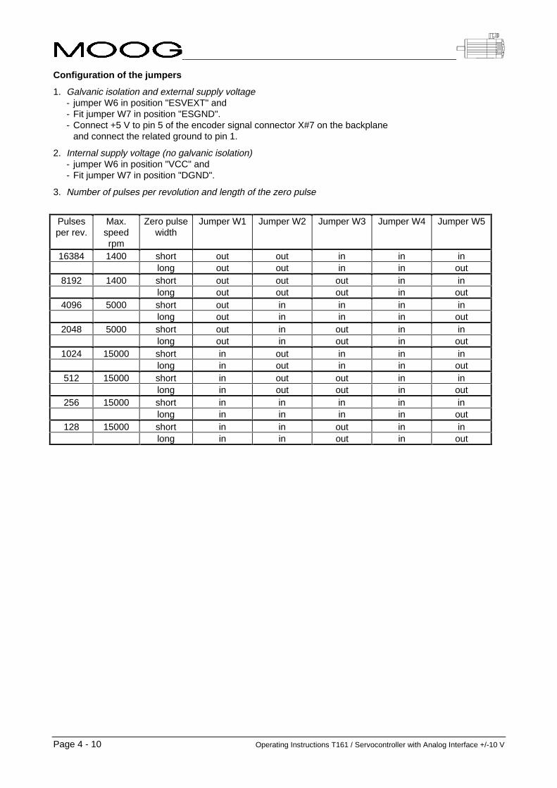
Configuration of the jumpers
1. Galvanic isolation and external supply voltage- jumper W6 in position "ESVEXT" and- Fit jumper W7 in position "ESGND".- Connect +5 V to pin 5 of the encoder signal connector X#7 on the backplane
and connect the related ground to pin 1.
2. Internal supply voltage (no galvanic isolation)- jumper W6 in position "VCC" and- Fit jumper W7 in position "DGND".
3. Number of pulses per revolution and length of the zero pulse
Pulsesper rev.
Max.speedrpm
Zero pulsewidth
Jumper W1 Jumper W2 Jumper W3 Jumper W4 Jumper W5
16384 1400 short out out in in inlong out out in in out
8192 1400 short out out out in inlong out out out in out
4096 5000 short out in in in inlong out in in in out
2048 5000 short out in out in inlong out in out in out
1024 15000 short in out in in inlong in out in in out
512 15000 short in out out in inlong in out out in out
256 15000 short in in in in inlong in in in in out
128 15000 short in in out in inlong in in out in out
Operating Instructions T161 / Servocontroller with Analog Interface +/-10 V Page 4 - 11
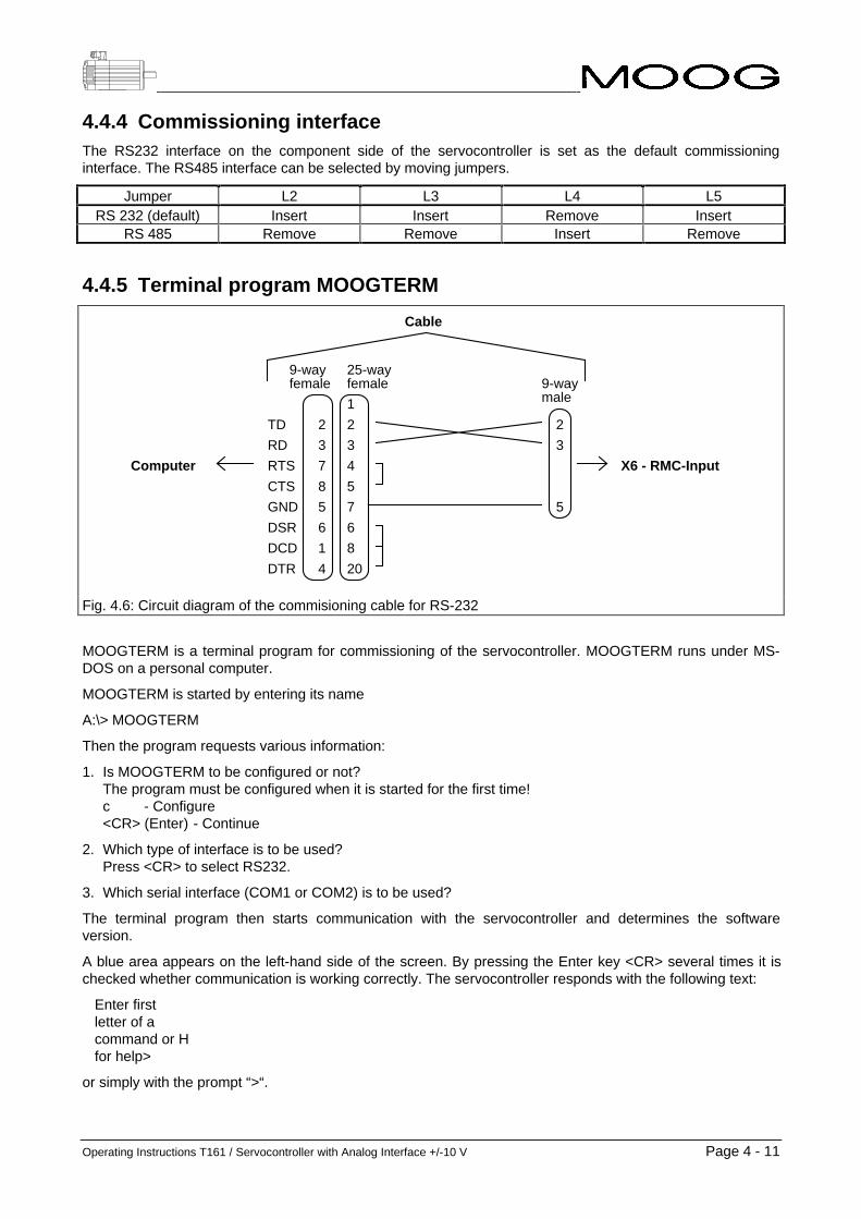
4.4.4 Commissioning interfaceThe RS232 interface on the component side of the servocontroller is set as the default commissioninginterface. The RS485 interface can be selected by moving jumpers.
Jumper L2 L3 L4 L5RS 232 (default) Insert Insert Remove Insert
RS 485 Remove Remove Insert Remove
4.4.5 Terminal program MOOGTERM
TD
RD
RTS
CTS
GND
DSR
DCD
DTR
9-way 25-way
2
3
7
8
5
6
1
4
1
2
3
4
5
7
6
8
20
female female 9-waymale
2
3
5
X6 - RMC-InputComputer
Cable
Fig. 4.6: Circuit diagram of the commisioning cable for RS-232
MOOGTERM is a terminal program for commissioning of the servocontroller. MOOGTERM runs under MS-DOS on a personal computer.
MOOGTERM is started by entering its name
A:\> MOOGTERM
Then the program requests various information:
1. Is MOOGTERM to be configured or not?The program must be configured when it is started for the first time!c - Configure<CR> (Enter) - Continue
2. Which type of interface is to be used?Press <CR> to select RS232.
3. Which serial interface (COM1 or COM2) is to be used?
The terminal program then starts communication with the servocontroller and determines the softwareversion.
A blue area appears on the left-hand side of the screen. By pressing the Enter key <CR> several times it ischecked whether communication is working correctly. The servocontroller responds with the following text:
Enter firstletter of acommand or Hfor help>
or simply with the prompt “>“.

Page 4 - 12 Operating Instructions T161 / Servocontroller with Analog Interface +/-10 V
4.4.6 Configuration and startup of the servocontrollerWhen the entire system has been wired correctly, the system can be switched on. Various LEDs now light onthe power supply unit (see Section "Power supply unit - diagnostics"). The red LED on each servocontrollerflashes.
The personal computer is connected with the servocontroller via the start up cable. Now the terminal programMOOGTERM can be started.
After the Enter key <CR> has been pressed several times, the servocontroller responds with the text:
Enter firstletter of acommand or Hfor help>
or simply with the prompt “>“.
Enter the motor type
The motor type must now be entered with the command "D":
DMotor:-e.g. D314..L10G424-400
G423-200
Saving the input data
The settings are saved by pressing "C". The servocontroller then requests the input of a four-digit code. Thiscode is used only for outputs and is displayed during the starting up sequence of the servocontroller.
The further settings (control parameters, encoder simulation, scaling) are described in the following sections.

Operating Instructions T161 / Servocontroller with Analog Interface +/-10 V Page 4 - 13
4.5 Digital control loop
4.5.1 Block diagram
Fig. 4.7: Block diagram of the digital control loop

Page 4 - 14 Operating Instructions T161 / Servocontroller with Analog Interface +/-10 V
4.5.2 List of commands(EPROMs B80806-00# and B80807-00#, # = Revision Index)
S/L * Input/output of all parameters PARAMETER INPUT/OUTPUTL - Output of the system configurationS/L N Input/output of the maximum speed for a 10 V input signalS/L R Input/output of the observer position error in [revs/10 V]S/L P Input/output of the proportional gain in [Nm/(rad/s)]S/L I Input/output of the integral time constant in [s]S/L J Input/output of the moment of inertia of the observer in [kgm²]S/L W Input/output of the cut-off frequency of the filter in [Hz]S/L Z Input/output of the attenuation of the filterS/L A Input/output of acceleration limitation for the actual speed (filter function, not a setpoint ramp!) in [rad/s²]
(May be adjusted only by trained MOOG engineers!)L M Output of the motor parametersL D Output of the axis number in RS485 modeS/L TA Input/output of the torque limitation in [Nm] in Automatic modeS/L TM Input/output of the torque limitation in [Nm] in Manual modeS/L LA Input/output of the speed limitation [rpm] in Automatic modeS/L LM Input/output of the speed limitation in [rpm] in Manual modeS/L E Braking deceleration for limit-switch inputs
P Setting mode for proportional gain PARAMETER SETTING MODESU Increase P by 5%D Decrease P by 5%Z Set P to zeroQ Return to main menuRET Return to main menu
I Setting mode for integral time constantU Increase I gain by 5% (decrease I time constant by 5%)D Decrease I gain by 5% (increase I time constant 5%)Z Set I gain to zero (set I time constant to infinite = 3 s)Q Return to main menuRET Return to main menu
J Setting mode for moment of inertia of observerU Increase JD Reduce JZ Set J to zeroQ Return to main menuRET Return to main menu
D Drive initialization SPECIAL COMMANDSC Save parameters permanently in EEPROMControl X Software warmstartControl T Upload/download the system parameter CAlt S Change the axis (active only in RS 485 mode)
H Help as help function HELP FUNCTION+ Upper help level- Reduced help level

Operating Instructions T161 / Servocontroller with Analog Interface +/-10 V Page 4 - 15
OC Selection of control mode OPTIONAL COMMANDS1 Torque mode2 Velocity mode
OE Available only with encoder simulation card B53000-001 (sold only as spare part for repairs)L Input of the number of pulses of the encoder simulation (number of lines)A Input of the zero pulse angleO Disable encoder simulation
OI Compensation of the input offsetOZ Automatic offset adjustOA Enable/disable reference input filter (input reference filter)OL Enable/disable limit-switch inputsOR Select reference source (compensator reference source)
1 Analog reference (external setpoint generation, default)2 Function generator (internal function generator)
OG Setting the function generatorN Setting the speed of the function generator (amplitude and offset in [rpm])T Setting the torque of the function generator (amplitude and offset in [Nm])P Setting the period in [s] and the duty cycle in [%] of the function generator
OF Programmable analog output (front panel options)1 dP/dt (actual speed)2 Filtered dP/dt (filtered actual speed)3 IDC (current monitor, corresponding to a DC motor)4 Observer estimated velocity5 Observer position error
OM Enable/disable Manual modeOD Enable/disable thermal protection softwareOT IT limit setting (for motors MOOG INC. 30x-xxx only)OO Enable/disable the observer (Observer velocity on/off)
?M Motor temperature in [°C] STATUS POLLS?B Temperature of the power output stage in [°C]?P Rotor position (motor shaft position) [0° .. 360°]?V Average speed in [rpm]?L Current limitation (limit settings) in [Amps]?F Fault messages?S Current status of the servocontroller (present controller status)
MI Enable the motor MOTOR-MODE COMMANDSMO Disable the motorMB Enable/disable (optional) motor brake (Release brake = open brake)MT Torque modeMV Velocity mode

Page 4 - 16 Operating Instructions T161 / Servocontroller with Analog Interface +/-10 V
4.6 Tuning the controller
Beware of mechanical hazards!Servomotors can accelerate highly dynamically. They also have an enormous torque. Thefollowing points must therefore be observed when commissioning the system:
• The danger zone around the motor must be cordoned off. The system must feature a guard door preventing personnel from reaching into or entering
the danger zone. If the guard door is opened, the drive system must be disconnectedfrom the supply voltage immediately. This is best done by de-energizing the contactorinserted before the MOOG power supply unit.
• The control parameters determine the dynamic and static behaviour of theservomotor.Incorrectly or wrongly set parameters can cause the servomotor to run at an excessivespeed (instable controller settings).
• If the drive is moved with the aid of the function generator, it should be noted that themotor speed and the repetition frequency are used to determine for how long and how farthe motor rotates in one direction. This must be noted if the machine is equipped withmechanical end stops.
The integrated function generator and the programmable analog outputs (X#5 Pin 3 and Pin 4) are used totune the controller.
4.6.1 The integrated function generatorThe servocontroller features an integrated function generator which can be used for setting the controller withthe aid of its step response. Speed references can be generated and fed into the control loop. With thecommand "OR", the function generator can be selected as the reference signal source (compensatorreference).
4.6.1.1 Generating a reference velocity curveFor the generation of a reference velocity curve, the function generator provides a square-wave signal withprogrammable frequency and amplitude.
OGN - to enter the amplitude and offset of the velocity reference:Func. Generator Speed Amplitude (speed amplitude)Func. Generator Speed Offset (speed offset)Unit: rpm
OGP - to enter the period of the square-wave signal:Unit: sec
- to enter the Func. Generator Duty Cycle (share of period of positive speed amplitude):Unit: %.
2IIVHW
$PSOLWXGH
t
Q�W�
3HULRG� �����
��� ��� 'XW\�&\FOH
Fig. 4.8: Programming the reference velocity curve n(t) with the function generator

Operating Instructions T161 / Servocontroller with Analog Interface +/-10 V Page 4 - 17
It should be noted that the reference velocity and the period determine how fast and how long the drivemoves in one direction. These values must be selected such that the drive does not move against the endstops of the machine.
4.6.2 Analog outputsThe servocontroller has two analog outputs which are used for the output of dynamic control processvariables to an oscilloscope. The outputs are available both on the backplane and on the front panel. On thefront panel, the outputs are covered by a black Lexan foil. You can either cut a hole in this foil or, preferably,carefully peel off the foil so that it can be fixed again afterwards. The freely programmable output isprogrammed with the command "OF...":
Output TP10 orX#5, Pin 3
Actual speed OF 1 *)
Filtered actual speed OF 2
Torque (current Idc) OF 3
Speed calculated by the observer OF 4
Difference between observer position and real position OF 5
*) default setting after the servocontroller is switched on (again).
The other analog output "TP3" or "X#5, Pin 4" is permanently set to torque (Idc) output.
+Scaling
• SpeedThe speed is scaled with the command "SN" (10 V correspond to how many rpm?).
• Observer Position ErrorThe observer position error is scaled with the command "SR" (10 V correspond to howmany revolutions?).

Page 4 - 18 Operating Instructions T161 / Servocontroller with Analog Interface +/-10 V
4.6.3 Tuning the controllerThis section describes how the controller is tuned by means of the step response. If the machine does notpermit this, another method has to be used. The speed control loop must be tuned first. It is important that nosaturation occurs during adjustment, since this would cause the controller to leave the linear range. For thisreason, the current must be observed (with the analog output TP3 or at X#5 Pin 4 on the backplane) in orderto ensure that it is not limited.
4.6.3.1 Tuning the speed control loopIn order to adjust the speed control loop, the drive must be switched to velocity mode and the functiongenerator must be selected as the reference signal source.
OR to select the function generator as the reference source.
The following inputs are then requested:- Func Generator Speed Amplitude (speed amplitude in rpm): enter the speed.- Func Generator Speed Offset (speed offset in rpm): enter the value "0".- Func Generator Torq. Amplitude (torque amplitude in Nm): enter the value "0".- Func Generator Torq. Offset (torque offset in Nm): enter the value "0".- Func Generator Period (period in sec): enter a low value.- Func Generator Duty Cycle (in %): leave this value set to "50".
OC to switch to velocity mode: enter option "2".
MO to cancel the enable signal for the motor.
MB to apply the brake: enter "N" for not releasing the brake.
OGN to enter the Func Generator Speed Amplitude (speed amplitude in rpm).
OGP to enter the period of the square-wave signal (period in sec).
SP to enter the proportional gain of the speed controller (in Nm/(rad/s)).Start with a low value and increase gradually!
SI to enter the integral time constant (in sec) of the speed controller.Select the maximum value (3 s)!
OF 1 to program the actual speed to the programmable analog output (TP10 or X#5, pin 3).
MI to enable the motor and release the brake.
Fig. 4.9 shows the reference speed and the actual speed:
..................... Time constant too short___________ Correctly adjusted system_ _ _ _ _ _ P gain too low
Fig. 4.9: Step response of the speed control loop

Operating Instructions T161 / Servocontroller with Analog Interface +/-10 V Page 4 - 19
The controller should be adjusted in accordance with Fig 4.9. Overshoots will occur if the proportional gain ofthe controller is set too high. The system will become slow if the controller gain is set too low.
The integral component determines the sensitivity of the control loop to disturbances from the load torque andprevents steady state speed errors. The disadvantage of this is, however, that the integral component has anegative effect on the stability of the control loop.
+Note: jog-key mode
Instead of the commands "SP", "SI" and "SJ", the commands "P", "I" and "J" can be used.These commands activate the corresponding jog-key mode, in which the following keys canbe used:
• U (Up)Increases the current value by 5%.
• D (Down)Decreases the current value by 5%.
• S (Set)For input of a new value.
• L (List)Displays the current value.
• Q (Quit)Terminates jog-key mode.
MOOG recommends use of the jog-key mode, since it reduces the risk of incorrect inputs toa great extend.

Page 4 - 20 Operating Instructions T161 / Servocontroller with Analog Interface +/-10 V
4.6.3.2 Cooperation with the higher-ranking control system
After the above adjustments, the servocontroller is still in function-generator mode, which means that itignores the analog interface. Therefore it must be set back to its normal operating mode (speed-controlledwith analog reference):
OR to select the analog reference as reference source.
Speed scaling
The control system provides the speed reference for the drive as an analog voltage. This voltage should bescaled such that the available voltage range is fully utilized, since this reduces the effects of disturbingvoltages and quantization noise.
An example:
• Assumptions:During movement, a maximum speed of 5000 rpm occurs and the control system can generate amaximum output voltage of 8 V.
• Calculation:In order to allow for drift and offsets of analog components and possible overshoots of the control loops, asafety margin of 10% is added to the maximum speed, which means that the 5000 rpm become 5500 rpm.When the higher ranking controller wants to set a speed of 5500 rpm, it generates an output voltage of8 V.
Setpoint_ speed * Scaling_ of_ control_ system Output_ voltage
5500 rpm *8 V
5500 rpm= 8V
Input_ voltage * Scaling_ of_ servocontroller Reference_ speed
8 V *x
10 V5500 rpm
x5500 rpm * 10 V
8 6875 rpm
Scaling " SN"6875 rpm
10 V
=
⇒
=
⇒ =
⇒ = =
⇒ =
The reference interface of the servocontroller has a range of -10 V .. +10 V.
+Remember to save the settings
Once the controllers have been set, the controller parameters should be saved in theEEPROM (command "C"). Before saving the settings, however, the servocontroller shouldbe set back to the correct control mode (speed-controlled) and the correct source for thereference signal (the analog interface) should be selected, since the current control modeand reference signal source are also saved in the EEPROM.
• OR Select the analog interface as the reference source.
• C to save the settingsThe servocontroller requests the input of a 4-digit code number.Any desired number, such as 1234, may be entered.

Operating Instructions T161 / Servocontroller with Analog Interface +/-10 V Page 4 - 21
4.6.4 The speed observer
This section describes the commissioning and adjustment of the MOOG speed observer. The use of thisobserver permits higher control-loop gains and a wider bandwidth of the speed control. With the aid of amodel of the control loop (motor and load), the observer calculates the observer estimated velocity. The userneeds to change only one optimization parameter in order to tune the observer as described below.
Drehzahl
Drehmoment
2 ms/div
1,6
Nm
/div
40 U
pm/d
iv
Fig. 4.10: Optimized speed step response
Optimizing the speed control
Fig. 4.10 shows a typical step response of an optimizedspeed control (the input signal can be generated by theintegrated function generator). The torque or current curvecan be accessed at the test points of the servocontroller. Thesame applies to the actual-speed value.
The reference input must be low enough to ensure that thecurrent controller does not reach limitation. Fig. 4.10 shows asingle overshoot of 24% in the speed step response and arise time of 12 ms.
Drehmoment
BeobachterLageabweichung
Jest zu klein
Jest zu groß
Jest richtig
2 ms/div
0,00
5 R
ev/d
iv1,
6 N
m/d
iv
Fig. 4.11: Setting the observer
Tuning the observer
The parameter "Observer moment of inertia Jest" is set first.The signal "Observer position error θerr" is set with thecommand OF5 and is available at the test points TP 3,7,10.
Fig. 4.11 shows the case "motor with load", i.e. Jest is toosmall (after initialization of the servocontroller, Jest=2 x JMotor).
After input of the command J, the following commands areavailable in observer mode:
U Jest up D Jest down
S Set Jest Z Set Jest to zero
L List Jest Q Quit (return to main menu)
If the total moment of inertia is already known, this value can be entered with the command "SJ". Fig. 4.11now shows θerr with Jest set correctly.

Page 4 - 22 Operating Instructions T161 / Servocontroller with Analog Interface +/-10 V
Drehmoment
BeobachterLageabweichung
2 ms/div0,00
5 R
ev/d
iv1,
6 N
m/d
iv
Fig. 4.12: Oscillations in the observer model(do not activate the observer!)
Caution:
If θerr oscillates considerably when the speed changes (seeFig. 4.12), the observer must not be activated! Only acorrectly tuned observer model may be inserted into thefeedback path.
During the final test of the observer, compare theobserverestimated speed (command "OF4") with the actualspeed of the drive (command "OF1"). These must beidentical.
Drehzahl
Drehmoment
2 ms/div
1,6
Nm
/div
40 U
pm/d
iv
Beobachteraus
Beobachterein
Fig. 4.13: Activating the observer
Activating the observer
The command "OO" activates the observer. Fig. 4.13 showsthe effect of the observer on the speed control loop. Note thatthe overshoot in the velocity curve has disappeared and thatthe disturbance on the torque curve is considerably reducedas well.
Drehzahl
Drehmoment
2 ms/div
1,6
Nm
/div
40 U
pm/d
iv
Beobachteraus
Beobachterein
Fig 4.14: System with/without observer
Final tuning of the servocontroller
A higher bandwidth can now be set (command "SW"; value upto about 600 Hz). Now the parameters P and I can also bemodified. Fig. 4.14 shows a comparison of system behaviourwith and without the observer. The system with observer hasa better rise time (2.2 ms instead of 12 ms) and a smallerovershoot.

Operating Instructions T161 / Servocontroller with Analog Interface +/-10 V Page 4 - 23
4.7 Diagnosis
4.7.1 LEDs
Fig. 4.15: Servocontroller T161 status LEDs
Status LEDs:
LED 1 (red) LED flashesThe servocontroller is booting (getting its parameters from the memory and configuring itselfwith them).When the servocontroller has completed booting, this LED goes out.If the servocontroller has never been configured previously, the LED continues to flash. In thiscase, the servocontroller must be configured (input of the motor type, etc.) via the serialinterface.LED lights in the case of a fault.If the servocontroller is enabled and a fault occurs, the green LED 3 goes out and the redLED 1 lights again.Enabling the servocontroller again deletes the stored faults and LED 1 is switched off.
LED 2(yellow)
Torque limitation active due to thermal overloadAs long as the torque limitation is active, the contact of the thermal limit relay for(X#5 / Pins 15 and 16) remains open and this LED lights.
LED 3(green)
EnableAs soon as the servocontroller is enabled this LED lights up.It is switched off when the servocontroller is disabled.LED 3 is switched off as well in the case of a fault (red LED 1 lights).
4.7.2 "System ready" relayRelay status Condition
Relay contact remainsopen.
- When the servocontroller is switched off completely
Relay contact closes. - If there is no fault present.
Relay contact opens. - When the servocontroller is switched off.- If a fault is present.

Page 4 - 24 Operating Instructions T161 / Servocontroller with Analog Interface +/-10 V
4.7.3 Getting fault information via MOOGTERMMOOGTERM is the commissioning program for the servocontroller and runs under MS-DOS on a personalcomputer. A description of this program can be found earlier in this section.
The fault memory of the servocontroller can be read out with the command "?F". There are two different typesof fault messages:
Fault text Meaning
Fault occurred A fault has occurred but is no longer present.The fault message is stored until the servocontroller is enabled again. Then the message isdeleted.
Fault present A fault has occurred and is still present.
Danger - high voltage!The servo drives operate with potentially lethal voltages.
For this reason:
• Disconnect the system from the mains supply. Before starting any work on the drive system, it must be disconnected from the power supply
and secured against inadvertent reconnection by means of the master switch.
• The servomotors must come to a complete stop.Rotating servomotors can generate potentially lethal voltages by acting as generators.
Beware of charged capacitors!The capacitors in the power supply may still be charged.
For this reason:
• Note the discharge time of the capacitors. The power supply contains capacitors which may be charged with up to 400 VDC. Wait at
least 5 minutes for the capacitors to become discharged after disconnecting the voltage.
• The voltage must then be measured between DC+ (X7/1) and DC- (X7/2). Work on the power supply must not start until the voltage has dropped below 5 V.
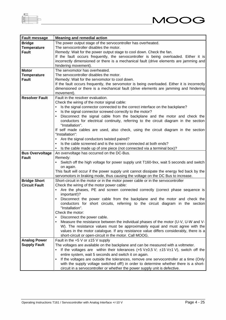
Operating Instructions T161 / Servocontroller with Analog Interface +/-10 V Page 4 - 25
Fault message Meaning and remedial actionBridgeTemperatureFault
The power output stage of the servocontroller has overheated.The servocontroller disables the motor.Remedy: Wait for the power output stage to cool down. Check the fan.If the fault occurs frequently, the servocontroller is being overloaded. Either it isincorrectly dimensioned or there is a mechanical fault (drive elements are jamming andhindering movement).
MotorTemperatureFault
The servomotor has overheated.The servocontroller disables the motor.Remedy: Wait for the servomotor to cool down.If the fault occurs frequently, the servomotor is being overloaded. Either it is incorrectlydimensioned or there is a mechanical fault (drive elements are jamming and hinderingmovement).
Resolver Fault Fault in the resolver evaluation.Check the wiring of the motor signal cable:• Is the signal connector connected to the correct interface on the backplane?• Is the signal connector screwed correctly to the motor?• Disconnect the signal cable from the backplane and the motor and check the
conductors for electrical continuity, referring to the circuit diagram in the section"Installation".
If self made cables are used, also check, using the circuit diagram in the section"Installation":• Are the signal conductors twisted paired?• Is the cable screened and is the screen connected at both ends?• Is the cable made up of one piece (not connected via a terminal box)?
Bus OvervoltageFault
An overvoltage has occurred on the DC-Bus.Remedy:• Switch off the high voltage for power supply unit T160-9xx, wait 5 seconds and switch
on again.This fault will occur if the power supply unit cannot dissipate the energy fed back by theservomotors in braking mode, thus causing the voltage on the DC Bus to increase.
Bridge ShortCircuit Fault
Short-circuit in the motor or in the motor power cable or in the servocontrollerCheck the wiring of the motor power cable:• Are the phases, PE and screen connected correctly (correct phase sequence is
important!)?• Disconnect the power cable from the backplane and the motor and check the
conductors for short circuits, referring to the circuit diagram in the section"Installation".
Check the motor:• Disconnect the power cable.• Measure the resistance between the individual phases of the motor (U-V, U-W and V-
W). The resistance values must be approximately equal and must agree with thevalues in the motor catalogue. If any resistance value differs considerably, there is ashort-circuit or open-circuit in the motor. Call MOOG.
Analog PowerSupply Fault
Fault in the +5 V or ±15 V supplyThe voltages are available on the backplane and can be measured with a voltmeter.• If the voltages are within their tolerances (+5 V±0,5 V; ±15 V±1 V), switch off the
entire system, wait 5 seconds and switch it on again.• If the voltages are outside the tolerances, remove one servocontroller at a time (Only
with the supply voltage switched off!) in order to determine whether there is a short-circuit in a servocontroller or whether the power supply unit is defective.

Page 4 - 26 Operating Instructions T161 / Servocontroller with Analog Interface +/-10 V
4.8 Ordering information
No. Description MOOG Order No.
1 Servocontroller, 8 Ampere, without encoder simulation
T161 - 901 # - 00 - B# - 2 -1#
2 Servocontroller, 20 Ampere without encoder simulation
T161 - 902 # - 00 - B# - 2 -1#
3 Servocontroller, 30 Ampere without encoder simulation
T161 - 903 # - 00 - B# - 2 -1#
4 Servocontroller, 60 Ampere without encoder simulation
T161 - 904 # - 00 - B# - 2 -1#
5 Encoder simulation card ESM III C09517-001
6 Encoder simulation card ESM II B94102-001
7 Commissioning software MOOGTERM(for IBM-compatible PC)3,5“ floppy disk5,25“ floppy disk
B47214-001B47214-002
8 Commissioning cable for PC (5 metres) B48424-105
9 Hand held terminal (without cable) B48426-002
10 Cable for hand held terminal (5 metres) B48423-003
# = Revision Index for hardware, software and optical design (from left to right)

Operating Instructions T161 / Servocontroller with Analog Interface +/-10 V / Ver.: Rev. c, 17.04.98 Page 5 - 1
5 Power supply unit T160-9xx
5 Power supply unit T160-9xx...........................................................................................15.1 Name plate............................................................................................................................................. 35.2 Functional description ......................................................................................................................... 45.3 Technical data ....................................................................................................................................... 5
5.3.1 Power connection ........................................................................................................................... 55.3.2 24 VDC input (optional)................................................................................................................... 65.3.3 Power output................................................................................................................................... 65.3.4 Power of the ballast circuit .............................................................................................................. 75.3.5 Dimensions and weights ................................................................................................................. 7
5.4 Diagnosis............................................................................................................................................... 85.4.1 LEDs ............................................................................................................................................... 85.4.2 Relay "Power supply unit OK"......................................................................................................... 9
5.5 Scope of delivery .................................................................................................................................. 95.6 Order data............................................................................................................................................ 10

Page 5 - 2 Operating Instructions T161 / Servocontroller with Analog Interface +/-10 V

Operating Instructions T161 / Servocontroller with Analog Interface +/-10 V Page 5 - 3
LED 1
LED 2
LED 4
LED 3
LED 5
LED 6
LED 7
X3
X4
X5
F1
JW1
Fig. 5.1: Front and side view of the power supply unit T160-9xx
5.1 Name plate
MOOG Ltd. Made in Ireland
Model:
SerNo:
7���������������
7����
MOOG Ltd. Made in Ireland
Model:
SerNo:
7���������������
7����
MOOG Ltd. Made in Ireland
Model:
SerNo:
7���������������
7����
# stands for the revisions index.This operating instruction applies for all revisions.
SerNo: T0123 stands for the serial number.The serial number is incremented with every part produced.
+The name plate identifies the product.For this reason:
• Check whether the name plate on the device matches the name plate illustrated above.
• This documentation must not be used for commissioning and startup if the name platesdo not match.
• Devices without name plate are not covered by the manufacturer’s warranty and must notbe put into operation.

Page 5 - 4 Operating Instructions T161 / Servocontroller with Analog Interface +/-10 V
5.2 Functional descriptionThe power supply unit has two functions:
1. Power supply for the servocontrollerThe power supply unit generates the voltages required by the servocontroller:
• DC bus voltage (nominal value 325 VDC) The servocontroller takes its energy from a DC bus buffered by capacitors. This DC voltage is
generated by the power supply unit by rectifying the AC voltage (nominal value 230 VAC).
• +5 V The servocontroller includes a microcomputer requiring a +5 V supply.
• ±15 V The servocontroller also includes analog circuits requiring a power supply of ±15 V.
2. Ballast circuitThe power supply unit regulates the DC bus voltage. The DC bus capacitors are charged when theservomotors feed back energy into the power supply unit in generator mode, thus increasing the DC busvoltage. By means of the ballast circuit, the capacitors are partially discharged via the ballast resistor untilthe nominal DC bus voltage is adjusted again.
Different types of power supply units
The power supply units can primarily be classified in two groups:
1. Power supplies with external 24 VDC supplyFor these power supply units 24 VDC must be supplied externally. The +5 V and ±15 V supplies aregenerated from these 24 VDC. This ensures that the microcomputer, the position feedback evaluation andan optional CAN bus remain fully functional if the power must be disconnected for operational reasons,e.g. following an Emergency SWITCH OFF.
2. Power supplies without external 24 VDC supplyAn external 24 VDC supply is not required for these power supply units. The microcomputer, the positionfeedback evaluation and an optional CAN bus stop their operation when the power is disconnected. Ifnecessary, homing cycle must be performed after switching the power on again.
The power supply units also differ with regard to the power dissipation of their ballast circuits.
+Warning:
Correct dimensioning of the ballast circuit is particularly important in conjunction with thefollowing applications:
• Lifting axisIf the lifting axis does not have a self-locking gear, the servomotor must brake when theload is lowered. The servomotor operates in generator mode in this case. The energy fedback must be converted into heat via the ballast circuit. It is therefore important to ensurethat the ballast circuit is dimensioned correctly and can dissipate the energy.
• Rapid deceleration of large massesConsiderable amounts of energy must be dissipated by the ballast circuit as well whenlarge masses are rapidly decelerated from high speeds. It should be noted that theshorter the braking time, the higher becomes the required peak braking power (energyper time unit). The ballast circuit must be dimensioned to dissipate not only the requiredcontinuous power, but also the peak power.

Operating Instructions T161 / Servocontroller with Analog Interface +/-10 V Page 5 - 5
5.3 Technical data
5.3.1 Power connectionThe power supply unit can be operated either with a one-phase or three-phase AC voltage:
Minimum Nominal Maximum
Supply voltage 207 VAC 230 VAC 254 VAC
Mains frequency 44 Hz 50 Hz 66 Hz
Fuse 16 A slow-blow *)
*) For 3-phase operation, a 3-phase automatic circuit-breaker must be used in order to ensure that allphases are tripped at the same time in the event of a fault!
Important: Isolating transformer requiredThe isolating transformer is required in order to maintain the specified isolation (creepagedistances and clearances) in relation to unprotected small-signal auxiliary voltages. Theisolating transformer must conform to standard EN 60204-1. The protective earth conductormust be connected.
If other precautions are taken,- the power supply unit can be connected directly to the mains supply for one-phase
operation,- an autotransformer can be used to adjust the voltage for three-phase operation.
One-phase operation:
In one-phase operation, the voltage between live and neutral is 230 VAC. An isolating transformer with 1:1transformation ratio must be used. The secondary terminals of the isolating transformer are connected toterminal X3-pin 2 and X3-pin 3. The protective earth conductor must also be connected.
Three-phase operation:
The nominal voltage between the power supply unit terminals must be equal to 230 VAC. The phase-to-phase voltage of a normal 3x400 VAC 3-phase mains supply must be stepped down to 3x230 VAC by meansof an isolating transformer connected to terminal X3. The protective earth conductor must be connected.
+Note:
Leakage currents flow on the PE conductor if no isolating transformer is used.The leakage current may exceed 3.5 mA under corresponding operating conditions. It istherefore recommended to connect an additional PE conductor of at least 10 mm2 to the rack(see VDE 0160).
The leakage currents are drastically reduced when using an isolating transformer.

Page 5 - 6 Operating Instructions T161 / Servocontroller with Analog Interface +/-10 V
5.3.2 24 VDC input (optional)The type of power supply unit used determines whether a 24 VDC power supply is required or not.
Power supply T160 - 901 # - 00 - 1# 24 VDC not required
Power supply T160 - 902 # - 00 - 1#Power supply T160 - 932 # - 00 - 1#
24 VDC required24 VDC required
Minimum Nominal Maximum
24 VDC input 20 VDC 24 VDC 35 VDC
Power consumption 20 Wplus 25 W
per servocontroller
Recommended fuse 10 Amps, slow-blow
A 3-phase rectifier is sufficient. It is not necessary to smooth the voltage.The 24 VDC power supply unit should be capable of delivering a short overload switch-on current.
Important: A 24 V power supply with reliable insulation mustbe used!The power supply providing the 24 VDC for the MOOG power supply unit must have areliable insulation to the mains voltage and must conform to standard EN 60950.
5.3.3 Power outputThe power supply unit supplies the servocontroller with power in the form of a DC voltage buffered bycapacitors.
Minimum Nominal MaximumDC bus voltage
(no-load operation)292 VDC 325 VDC 359 VDC
Power: Continuous power Short-time for 3 sec Short-time for 1 sec3-phase operation
with fan7.5 kW 10.0 kW 15.0 kW
1-phase operationwith fan
2.5 kW 3.7 kW 5.0 kW
3-phase operationwithout fan
2.5 kW 5.0 kW 8.0 kW
1-phase operationwithout fan
0.8 kW 1.2 kW 1.6 kW
+Warning:A fan is required if more than four servocontrollers are installed.Then the fans must be switched on as soon as voltage is applied the power supply. If thepower supply requires an external 24 VDC supply, the fan must be switched on as soon asthe 24 VDC supply is connected.

Operating Instructions T161 / Servocontroller with Analog Interface +/-10 V Page 5 - 7
5.3.4 Power of the ballast circuitPower supply unit External ballast resistor Continuous ballast power Peak ballast power
T160-901# -00-1# orT160-902# -00-1#
None 40 W 2,800 Wfor 100 ms
50 Ohm, 225 Watt 200 W 2,800 Wfor 300 ms
10 Ohm, 350 Watt 235 W 16,900 Wfor 100 ms
T160-932# -00-1# 10 Ohm 900 W 14, 000 Wfor 160 ms
Maximum permissible DC bus voltage: 400 VDC
Nominal DC bus voltage: 325 VDC
Capacitance in the DC bus: 2,800 µF
Switch on voltage for ballast resistor: 380 VDC ± 5 %
Switch off (again) voltage for ballast resistor: 373 VDC ± 5 %
5.3.5 Dimensions and weightsModel: T160-901# -00-1#
T160-902# -00-1#T160-932# -00-1#
Weight: 1.9 kg 1.9 kg
Installation size (W x D x H in mm): 60.96 x 226.90 x 262.90 60.96 x 226.90 x 262.90
Ballast resistor
L
S2
S1
Fig. 5.2: Ballast resistor
Dimensions:
Ballast resistor 10 Ohm / 350 W
L (Hole spacing): 283 mmS1 (Screw hole): 8 mmS2 (Screw hole): for M4
Ballast resistor 10 Ohm / 1000 W
L (Hole spacing): 421 mmS1 (Screw hole): 9 mmS2 (Screw hole): 9.2 mm

Page 5 - 8 Operating Instructions T161 / Servocontroller with Analog Interface +/-10 V
5.4 Diagnosis
5.4.1 LEDs
+
LED 1 DC bus voltage ready (green)This LED lights up as soon as the power (230 VAC) is present.This LED must light during operation.
The LED slowly goes out when the power is switched off.
LED 2 ±15 VDC, +5 VDC ready (green)This LED lights up as soon as the ±15 VDCand +5 VDC are presentwithin their tolerances. This LED must light during operation.
LED 3 Braking resistor fuse defective (red)The fuse for the ballast resistor is defective and must be replaced.
LED 4 Power supply overtemperature (red)The power supply unit has overheated. It is being overloaded by theapplication, or a fault has occurred which has imposed an additional loadon the power supply unit.
LED 5 DC bus voltage >400 VDC (red)During braking the load, the motors have fed back too much power ingenerator mode. The ballast resistor of the power supply unit has beenoverloaded.
LED 6 Ballast resistor active (yellow) This LED may light up shortly when the servomotors feed back power in
generator mode. The ballast resistor is connected as long as the LEDremains alight.
The LED lights up when the high voltage is disconnected thus indicating that theDC bus circuit is being discharged via the ballast resistor.
LED 7 Loss of phase (red) One of the phases has failed in 3-phase operation. This fault is also indicated if
the power supply unit is configured for 3-phase operation but operatedfrom only one phase.
LED 3, 4, 5, 7: When a fault occurs the relay "Power supply unit OK" (X5/Pin 5/6) opens.The only fault latched is bus overvoltage (LED 5). This has to be reset.
LED 3, 4, 5: When a fault occurs, a fault signal is generated in all servocontrollers.The servocontrollers cannot be reenabled in as long as the fault is present.
5.4.1.1 Resetting the bus overvoltage fault message (LED 5)
Power supply 160-901 Switch off power supply unit. Wait 5 seconds and switch on again.
Power supply 160-902and T160-932
Switch off the mains supply (230 VAC) of the power supply unit. The external24 VDC supply does not have to be switched off. Wait 5 seconds and switch onagain.

Operating Instructions T161 / Servocontroller with Analog Interface +/-10 V Page 5 - 9
5.4.2 Relay "Power supply unit OK"
Relay status Condition
Relay remains open When power supply unit is switched off completely.When only 24 VDC are applied to the power supply unit.During softstart.
Relay contact closes When there is no fault present AND the softstart sequence is finished.
Relay contact breaks When the mains voltage is disconnected.When one phase fails in 3-phase operation.When the 24 VDC supply voltage fails.When the +5 V generated by the power supply unit fails (required for the relay).When an overvoltage occurs on the DC bus.
5.5 Scope of deliveryThe scope of delivery must be checked to ensure that the correct power supply unit has been ordered anddelivered.
T160 - 901 # - 00 - 1#andT160 - 902 # - 00 - 1#
The scope of delivery includes the following parts forthese power supply units:
- The power supply unit as such- One 1.6 A fuse installed in the power supply- One 2.5 A fuse- One 8 A fuse- One instruction leaflet
T160 - 932 # - 00 - 1# The scope of delivery includes the following parts forthis power supply unit
- The power supply unit as such- One 10 A fuse installed in the power supply
The ballast resistor required for operation is not included inthe scope of supply and must be ordered separately.

Page 5 - 10 Operating Instructions T161 / Servocontroller with Analog Interface +/-10 V
5.6 Order dataNo. Description MOOG Order No.
1 Power supply unit, no external 24 V supplyBallast circuit 40 W/2800 W
T160 - 901 # - 00 - 1#
2 Power supply unit with external 24 V supplyBallast circuit 40 W/2800 W
T160 - 902 # - 00 - 1#
3 Ballast resistor 10 Ohm/350 W A76178-002
4 Spare fuse F1, Siba 1.6 A/415 V/slow-blow B94138-001-600
5 Spare fuse F1, Siba 2.5 A/415 V/slow-blow B94138-002-500
6 Spare fuse F1, Siba 8 A/415 V/slow-blow B94138-008-000
7 Ballast resistor 50 Ohm/200 Was replacement part in existing systems
A76178-001
8 Power supply unit, with external 24 V supplyBallast circuit 900 W/14000 W
(Order ballast resistor together with power supplyunit!)
T160 - 932 # - 00 - 1#
9 Ballast resistor 10 Ohm/1000 W A76178-003
10 Spare fuse F1, Siba 10 A/415 V/slow-blow B94138-010-000
EMC accessories
11 Ferrite cores External supplier:Neosid Pemetzrieder KGPostfach 134458553 Halver 1GermanyTel.: +49-2353-710Fax: +49-2353-7154
12 Mains filters from Schaffner3-phase:FN251-XX-07FN351-XX-29
1-phase:FN250-XX-07FN350-XX-29
The rated current must be specified in place ofXX,e.g. 16 for 16 A
Schaffner Elektronik GmbHSchoemperlenstrasse 12B76185 KarlsruheTel.: +0049-721-569-10Fax: +0049-721-569-110
Schaffner Elektronik AGCH-4708 LuterbachSwitzerlandTel.: +0041-65-802-626Fax: +0041-65-802-641
13 Mains filters from Siemens3-phase:B84143-AXX-R
1-phase:B84142-BXX-R
The rated current must be specified in place ofXX,e.g. 16 for 16 A
Siemens AGRichard Strauss Strasse 7681679 MünchenTel.: +0049-89-9221-0Fax: +0049-89-9221-4390
Operating Instructions T161 / Servocontroller with Analog Interface +/-10 V / Ver.: Rev. c, 17.04.98 Page 6 - 1
6 Rack and Backplane
6 Rack and Backplane .......................................................................................................16.1 Rack ....................................................................................................................................................... 3
6.1.1 Filler panels..................................................................................................................................... 36.1.2 Fans................................................................................................................................................ 4
6.2 Backplanes ............................................................................................................................................ 56.2.1 Dimensions ..................................................................................................................................... 56.2.2 Backplane overview ........................................................................................................................ 6
6.3 Backplane with front connectors ........................................................................................................ 76.4 Backplane Connections ....................................................................................................................... 8
6.4.1 T160-9xx Power Supply Connections............................................................................................. 86.4.2 T161-90x Servocontroller Connections........................................................................................... 96.4.3 Commissioning interface connector X6 ........................................................................................ 106.4.4 Fan Connector X9......................................................................................................................... 11
6.5 Order data............................................................................................................................................ 12

Page 6 - 2 Operating Instructions T161 / Servocontroller with Analog Interface +/-10 V

Operating Instructions T161 / Servocontroller with Analog Interface +/-10 V Page 6 - 3
6.1 Rack
Fig. 6.1: Rack dimensions (1 HP = 5.08 mm)
6.1.1 Filler panelsWidth 12 HP: For covering unused slots in the rack.
Width 6 HP: For covering the gap (1/2 slot) when using a T161-904 servocontroller in the rack.
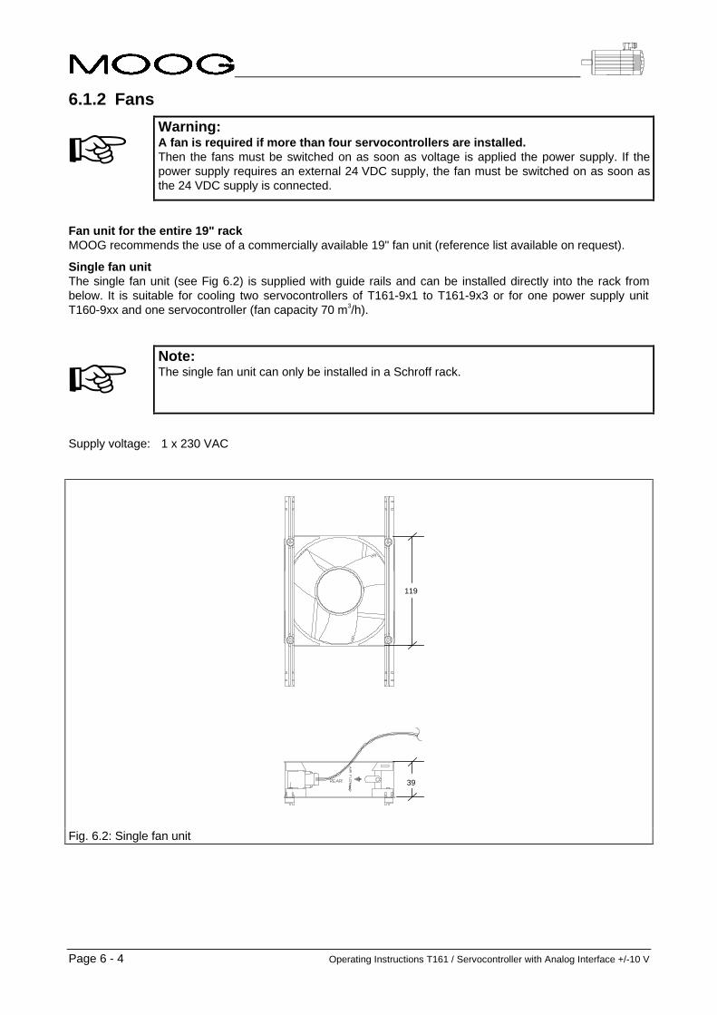
Page 6 - 4 Operating Instructions T161 / Servocontroller with Analog Interface +/-10 V
6.1.2 Fans
+Warning:A fan is required if more than four servocontrollers are installed.Then the fans must be switched on as soon as voltage is applied the power supply. If thepower supply requires an external 24 VDC supply, the fan must be switched on as soon asthe 24 VDC supply is connected.
Fan unit for the entire 19" rackMOOG recommends the use of a commercially available 19" fan unit (reference list available on request).
Single fan unitThe single fan unit (see Fig 6.2) is supplied with guide rails and can be installed directly into the rack frombelow. It is suitable for cooling two servocontrollers of T161-9x1 to T161-9x3 or for one power supply unitT160-9xx and one servocontroller (fan capacity 70 m3/h).
+Note:The single fan unit can only be installed in a Schroff rack.
Supply voltage: 1 x 230 VAC
119
39
Fig. 6.2: Single fan unit

Operating Instructions T161 / Servocontroller with Analog Interface +/-10 V Page 6 - 5
6.2 Backplanes
6.2.1 Dimensions
Fig. 6.3: Illustration of a standard backplane
6-axis backplane
The 6-axis backplane can accommodate a power supply unit and up to six servocontrollers of type T161-9x1to T161-9x3. It can also be delivered complete with rack. A servocontroller of type T161-9x4 occupies1.5 slots.Dimensions (W x H in mm): 429.26 x 263.91
4-axis backplane
The 4-axis backplane can accommodate a power supply unit and up to four servocontrollers of type T161-9x1to T161-9x3. A servocontroller of type T161-9x4 occupies 1.5 slots.Dimensions (W x H in mm): 304.8 x 265.9
2-axis backplane
The 2-axis backplane can accommodate a power supply unit and one or two servocontrollers of typeT161-9x1 to T161-9x3. A servocontroller of type T161-9x4 occupies 1.5 slots.Dimensions (W x H in mm): 182.88 x 265.9
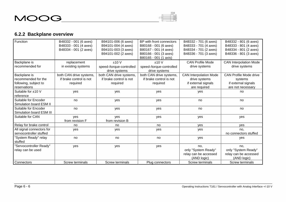
Page 6 - 6 Operating Instructions T161 / Servocontroller with Analog Interface +/-10 V
6.2.2 Backplane overviewFunction B48332 - 001 (6 axes)
B48333 - 001 (4 axes)B48334 - 001 (2 axes)
B94101-006 (6 axes)B94101-004 (4 axes)B94101-003 (3 axes)B94101-002 (2 axes)
BP with front connectorsB80168 - 001 (6 axes)B80167 - 001 (4 axes)B80166 - 001 (3 axes)B80165 - 001 (1 axis)
B48332 - 701 (6 axes)B48333 - 701 (4 axes)B48334 - 701 (2 axes)B48336 - 701 (3 axes)
B48332 - 801 (6 axes)B48333 - 801 (4 axes)B48334 - 801 (2 axes)B48336 - 801 (3 axes)
Backplane isrecommended for
replacementin existing systems
±10 Vspeed-/torque-controlled
drive systems
±10 Vspeed-/torque-controlled
drive systems
CAN Profile Modedrive systems
CAN Interpolation Modedrive systems
Backplane isrecommended for thefollowing, subject toreservations
both CAN drive systems,if brake control is not
required
both CAN drive systems,if brake control is not
required
both CAN drive systems,if brake control is not
required
CAN Interpolation Modedrive systems
if external signalsare required
CAN Profile Mode drivesystems
if external signalsare not necessary
Suitable for ±10 Vreference
yes yes yes yes no
Suitable for EncoderSimulation board ESM II
no yes yes no no
Suitable for EncoderSimulation board ESM III
no yes yes no no
Suitable for CAN yesfrom revision F
yesfrom revision B
yes yes yes
Relay for brake control no no no yes yesAll signal connectors forservocontroller stuffed
yes yes yes yes no,no connectors stuffed
"System Ready" relaystuffed
no no no yes yes
"Servocontroller Ready"relay can be used
yes yes yes no,only "System Ready"
relay can be accessed(AND logic)
no,only "System Ready"
relay can be accessed(AND logic)
Connectors Screw terminals Screw terminals Plug connectors Screw terminals Screw terminals

Operating Instructions T161 / Servocontroller with Analog Interface +/-10 V Page 6 - 7
6.3 Backplane with front connectors
U V WB+ B-
Caution !
+ ImportantThe pin assignment of the motorphases U, V, W is different from that ofother backplanes!
45 mm
89 mm
X10 = X6
+ NoteThe pin assignment of the resolverterminal and of the encoder interfacecorrespond with the pin assignmentof the relevant sub-D connector onthe other backplane types.
Fig. 6.4: Backplane with front connectors, pin assignment

Page 6 - 8 Operating Instructions T161 / Servocontroller with Analog Interface +/-10 V
6.4 Backplane Connections
6.4.1 T160-9xx Power Supply Connections
6.4.1.1 Power Supply Connector X3Type: Phoenix GSMKDS3 (angled screw terminal))Wire cross-sectional area: max. 3 mm2
Pin assignment:Pin 1: PE Protective Earth Input/Output ReferencePin 2: L1 Mains Input, Phase 1, 230 Vrms AC 50/60 Hz Input, Ref: PE (X3/1)Pin 3: L2 Mains Input, Phase 2, 230 Vrms AC 50/60 Hz Input, Ref: PE (X3/1)Pin 4: L3 Mains Input, Phase 3, 230 Vrms AC 50/60 Hz Input, Ref:PE (X3/1)Pin 5: PE Protective Earth Input/Output Reference
6.4.1.2 External Bleed Resistor Connector X4Type: Phoenix GSMKDS3 (angled screw terminal)Wire cross-sectional area: max. 3 mm2
Pin assignment:Pin 1: ReGen1 External Bleed Resistor 1 Output, Ref:ReGen2Pin 2: ReGen2 External Bleed Resistor 2 OutputPin 3: PE Protective Earth Input/Output ReferencePin 4: NC Not Connected
6.4.1.3 Low Voltage Power and Status Connector X5Type: Phoenix GSMKDS1,5 (angled screw terminal)Wire cross-sectional area: max. 1,5 mm2
Pin assignment:Pin 1: 24 V B+ 24 V Brake Supply Plus Input, Ref:24 V B- (X5/2)Pin 2: 24 V B- 24 V Brake Supply Ground Input ReferencePin 3: 24 V E+ 24 V External Supply Plus (Optional) Input, Ref: 24 V E- (X5/4)Pin 4: 24 V E- 24 V External Supply Ground (Optional) Input ReferencePin 5: PSRly1 Power Supply OK Relay, Pin 1 Output, Ref: PSRly2 (X5/6)Pin 6: PSRly2 Power Supply OK Relay, Pin 2 Output ReferencePin 7: PE Protective Earth Input/Output ReferencePin 8: +5 V +5 V Power Supply Output Output, Ref: DGND (X5/12)Pin 9: +15 V +15 V Power Supply Output Output, Ref: AGND (X5/11)Pin 10: -15 V -15 V Power Supply Output Output, Ref: AGND (X5/11)Pin 11: AGND Analog Ground Input/Output ReferencePin 12: DGND Digital Ground Input/Output ReferencePin 13: SRRly1 System Ready Relay, Pin 1 (Optional) Output, Ref: SRRly2 (X5/14)Pin 14: SRRly2 System Ready Relay, Pin 2 (Optional) Output ReferencePin 15: Dig. Input Digital input for servocontroller (function depends on
servocontroller and backplane type)Input, Ref: ExtIO_GND ofservocontroller (Xµ5/14)
6.4.1.4 DC Bus Connector X7Type: Phoenix GSMKDS3 (angled screw terminal)Wire cross-sectional area: max. 3 mm2
Pin assignment:Pin 1: DC+ High Power DC Bus Plus Output, Ref:DC- (X7/2)Pin 2: DC- High Power DC Bus Minus Output ReferencePin 3: PE Protective Earth Input/Output Reference

Operating Instructions T161 / Servocontroller with Analog Interface +/-10 V Page 6 - 9
6.4.2 T161-90x Servocontroller ConnectionsServocontroller µ (µ = A ... F)
6.4.2.1 Power Connector Xµ4Type: Phoenix GSMKDS3 (angled screw terminal)Wire cross-sectional area: max. 3 mm2
Pinbelegung:Pin 1: Brake+ Motor Brake Connection, Plus (Optional) Input, Ref: Brake- (Xµ4/2)Pin 2: Brake- Motor Brake Connection, Minus (Optional) Input ReferencePin 3: PE Protective Earth Input/Output ReferencePin 4: PE Protective Earth Input/Output ReferencePin 5: Motor_W *) Motor phase W Output, Ref: PE (Xµ4/4)Pin 6: Motor_V *) Motor phase V Output, Ref: PE (Xµ4/4)Pin 7: Motor_U *) Motor phase U Output, Ref: PE (Xµ4/4)
*) for Backplane B80165-001, B80166-001, B80167-001, B80168-001 applies:Pin5 = Motor phase U, Pin 6 = Motor phase V, Pin 7 = Motor phase W.
Motor connector pinout:Motor: Pin assignment (brake+: B+ and brake-: B-)G422 Pin 5: B+ Pin 6: B- Pin 1: W Pin 4: V Pin 2: UG423 Pin 5: B+ Pin 6: B- Pin 1: W Pin 4: V Pin 2: UG424 Pin 5: B+ Pin 6: B- Pin 1: W Pin 4: V Pin 2: UG425 Pin +: B+ Pin -: B- Pin W: W Pin V: V Pin U: U
6.4.2.2 Resolver Connector Xµ6Type: 9 pin Sub-D connector, female Motor connector pin assignment
Pin 1: S3 Resolver Feedback, SIN + Input Pin 2Pin 2: Thrm1 Motor Thermistor, Pin 1 Input, Ref: DGND
(Xµ6/5)Pin 5
Pin 3: S2 Resolver Feedback, COS + Input Pin 3Pin 4: R1 Resolver Supply Plus Output, Ref: R (Xµ/6) Pin 7Pin 5: Thrm2 Motor Thermistor, Pin 2 Input Pin 6Pin 6: S1 Resolver Feedback, SIN - Input Pin 1Pin 7: PE Protective Earth Input/Output ReferencePin 8: S4 Resolver Feedback, COS - Input Pin 4Pin 9: R2 Resolver Supply Minus Input Pin 8
6.4.2.3 I/O Connector Xµ5Type: Phoenix GSMKDS1,5 (angled screw terminal)Wire cross-sectional area: max. 1,5 mm2
Pin assignment:Pin 1: SysRdy1 System Ready Relay, Pin 1 Output, Ref: SysRdy2 (Xµ5/2)Pin 2: SysRdy2 System Ready Relay, Pin 2 OutputPin 3: PrAnaOut Programmable Analog Output (+/-10 V)
Default: Actual Velocity MonitorOutput, Ref: AGND (Xµ5/5)
Pin 4: IDC Equivalent DC Motor Current Monitor (+/-10 V) Output, Ref: AGND (Xµ5/5)Pin 5: AGND Analog Ground Input/Output ReferencePin 6: Dig. Input_1 Digital Input 1 (function: see section 4) Input, Ref: ExtIO_GND (Xµ5/14)Pin 7: Dig. Input_2 Digital Input 2 (function: see section 4) Input, Ref: ExtIO_GND (Xµ5/14)Pin 8: PE Protective Earth Input/Output ReferencePin 9: Dig. Input_3 Digital Input 1 (function: see section 4) Input, Ref: ExtIO_GND (Xµ5/14)Pin 10: Enable Axis Enable Input Input, Ref: ExtIO_GND (Xµ5/14)Pin 11: PE Protective Earth Input/Output ReferencePin 12: Dig. Input_4 Digital Input 1 (function: see section 4) Input, Ref: ExtIO_GND (Xµ5/14)Pin 13: ExtIO_V+ External I/O Supply Voltage Input InputPin 14: ExtIO_GND External I/O Ground
Input Reference für Xµ5 Pin 6, 7, 9, 10, 12Input
Pin 15: ThrmRly1 Thermal Limit Relay, Pin 1 Output, Ref: ThrmRly2 (Xµ5/16)Pin 16: ThrmRly2 Thermal Limit Relay, Pin 2 OutputPin 17: Analog Input_2+ Analog Input 2, Plus (function: see section 4) Input, Ref: Analog Input_2- (Xµ5/18)Pin 18 Analog Input_2- Analog Input 2, Minus (function: see section 4) InputPin 19: Analog Input_1+ Analog Input 1, Plus (function: see section 4) Input, Ref: Analog Input_1- (Xµ5/20)Pin 20: Analog Input_1- Analog Input 1, Minus (function: see section 4) Input

Page 6 - 10 Operating Instructions T161 / Servocontroller with Analog Interface +/-10 V
6.4.2.4 Encoder Simulation Connector Xµ7Type: 9 pin Sub-D connector, male
Pin assignment:Pin 1: GNDExtES External Ground Encoder Simulation Input/Output ReferncePin 2: /M Negated Reference Pulse Output, Ref: GNDExtES or GNDIntES
(internal ground encoder simulation);for differential output: Ref: M (Xµ7/6)
Pin 3: /B Negated Channel B Output, Ref: GNDExtES or GNDIntES(internal ground encoder simulation);for differential output: Ref: B (Xµ7/7)
Pin 4: /A Negated Channel A Output, Ref: GNDExtES or GNDIntES(internal ground encoder simulation);for differential output: Ref: A (Xµ7/8)
Pin 5: VExtES External Encoder Simulation Supply Voltage Input, Ref: GNDExtES (Xµ7/1)Pin 6: M Reference Pulse Output, Ref: GNDExtES or GNDIntES
(internal ground encoder simulation);for differential output: Ref: /M (Xµ7/2)
Pin 7: B Channel B Output, Ref: GNDExtES or GNDIntES(internal ground encoder simulation);for differential output: Ref: /B (Xµ7/3)
Pin 8: A Channel A Output, Ref: GNDExtES or GNDIntES(internal ground encoder simulation);for differential output: Ref: /A (Xµ7/4)
Pin 9: Shield Shield (connected to Protective Earth)
6.4.3 Commissioning interface connector X6
6.4.3.1 Interface connector X6/RS232Type: 9 pin sub-D connector, femaleLocation: Front panel of the controller T161-90x
Pin assignment:Pin 1: N/C Not ConnectedPin 2: RxD Read Data Input Input, Ref.: DGND (X6/5)Pin 3: TxD Transfer Data Output Output, Ref.: DGND (X6/5)Pin 4: N/C Not ConnectedPin 5: DGND Digital Ground Input/Output ReferencePin 6: PE Protective Earth Input/Output ReferencePin 7: N/C Not ConnectedPin 8: N/C Not ConnectedPin 9: +5 V +5 V Output Supply Voltage Output, Ref.: DGND (X6/5)Interface protocol: Baudrate: 9600
Startbits: 1Databits: 7Paritybit: ignoredStopbits: 2
6.4.3.2 Interface connector X6/RS485/CANType: 9 pin sub-D connector, maleLocation: Backplane
Pin assignment:Pin 1: CAN-BUS Digital Serial Input/Output (Option)Pin 2: CAN-BUS Digital Serial Input/Output (Option)Pin 3: RS485+ RS485 Bus Interface, Plus Input/OutputPin 4: RS485- RS485 Bus Interface, Minus Input/OutputPin 6: PE Protective Earth Input/Output ReferencePin 7: N/C Input/Output ReferencePin 8: N/CPin 9: N/C

Operating Instructions T161 / Servocontroller with Analog Interface +/-10 V Page 6 - 11
6.4.4 Fan Connector X9Type: Phoenix SMKDS1,5 (angled screw terminal)Wire cross-sectional area: max. 1,5 mm2
Pin assignment:Pin 1: L1 Mains Phase 1, 230 Vrms AC 50/60 Hz Output, Ref: L2 (X9/2)Pin 2: L2 Mains Phase 2, 230 Vrms AC 50/60 Hz OutputPin 3: L1 Mains Phase 1, 230 Vrms AC 50/60 Hz Output, Ref: L2 (X9/4)Pin 4: L2 Mains Phase 2, 230 Vrms AC 50/60 Hz OutputPin 5: L1 Mains Phase 1, 230 Vrms AC 50/60 Hz Output, Ref: L2 (X9/6)Pin 6: L2 Mains Phase 2, 230 Vrms AC 50/60 Hz Output

Page 6 - 12 Operating Instructions T161 / Servocontroller with Analog Interface +/-10 V
6.5 Order data
No. Description MOOG Order No.
1 Backplanes See "Backplane overview"
2 Rack (basic version) B47359-001
3 Filler panel 12 HP (for unused slots) B53473-001
4 Filler panel 6 HP (for T161-9x4) B80016-001
5 Single fan unit B53498-001
6 Rack conforming to EMC requirements,comprising:
20845-311, quantity: 1Europac Lab HF Subrack Kit(84 HP x 6 U x 340 mm)
20845-175, quantity: 1Shielded backplane (84 TE x 6 HE)
30845-253, quantity: 2Perforated strip (84 TE)
30819-594, quantity: 4Threaded strip (84 TE)
21100-275, quantity: 1Stud bolt
30837-619, quantity: 2Module rail, rear (84 TE)
30837-200, quantity: 1Profiled rail (84 TE)
60817-061, quantity: 4Insulating strip
21100-824, quantity: 1Locating pins to secure the insulating strip
Schroff GmbHLangenalber Strasse 96-100D-75334 Straubenhardt
Germany
Tel.: +0049-7082-794-0Fax: +0049-7082-794-200
Important:This is a standard rack made by Schroff. Thereare no grommets in the rack upon delivery. Theyhave to be inserted by the customer.
Operating Instructions T161 / Servocontroller with Analog Interface +/-10 V / Ver.: Rev. c, 17.04.98 Page 7 - 1
7 Servomotors
7 Servomotors....................................................................................................................17.1 Nameplate.............................................................................................................................................. 3
7.1.1 Motor type for series G400 servomotors......................................................................................... 37.2 Principal operation of a brushless servomotor ................................................................................. 47.3 Technical data ....................................................................................................................................... 6
7.3.1 Standards for MOOG Motors.......................................................................................................... 67.3.2 Tolerances of the shaft and flange.................................................................................................. 97.3.3 Operating and ambient conditions .................................................................................................. 97.3.4 Performance data ......................................................................................................................... 107.3.5 Mounting dimensions of MOOG motors........................................................................................ 11
7.4 Installation instructions ..................................................................................................................... 127.4.1 Safety instructions......................................................................................................................... 127.4.2 Mechanical installation.................................................................................................................. 147.4.3 Electrical interfaces....................................................................................................................... 15
7.5 Partnumber cross reference.............................................................................................................. 177.6 If repairs are required ......................................................................................................................... 17

Page 7 - 2 Operating Instructions T161 / Servocontroller with Analog Interface +/-10 V

Operating Instructions T161 / Servocontroller with Analog Interface +/-10 V Page 7 - 3
7.1 Nameplate
Fig. 7.1: nameplate with engraved data (values merely as example)
S/N: serial numberDate: production quarter and yearModel: motor model numberType: electric model, description optional brakenN: nominal speed (speed at PN)nmax: maximum speedPN: nominal power (maximum continuous power)J: moment of inertiaM0: continuous stall torqueI0: continuous stall currentRtt: terminal to terminal resistanceUd: bus voltage
Further motor data can be found in the catalogue.
+The name plate identifies the product.For this reason:
• Check whether the name plate on the motor matches the name plate illustrated above.
• This documentation must not be used for commissioning and startup if the name platesdo not match.
• Devices without name plate are not covered by the manufacturer’s warranty and mustnot be put into operation.
7.1.1 Motor type for series G400 servomotorsAll motor specific data in this handbook is associated to flange size and length of the motors. Flange size andstandard length are determined as follows.
Motor size: Determined by the 4th digit of the model number (e.g. Size G4x2-in the model numberG422-414) and 2nd digit of the model type (e.g. G2L10).
Standard length: Can be determined by means of the partnumber cross reference (see table 7.9) by the 6thdigit of the model number (e.g. length G4xx-4xx in the model number G422-414). Theeasier way is to look at the 4th and 5th digit of the model type on the nameplate (e.g.G2L10).
Model type: A model type designation (e.g. G2L10) is described by the following scheme:GxLyyz with x = motor size; yy = motor length; z = electric model (dropped for standardmotors).
Brake: The minimum torque of an optional brake is added to the model type on the nameplate (forinstance G2L10, brake 0,9 Nm).

Page 7 - 4 Operating Instructions T161 / Servocontroller with Analog Interface +/-10 V
7.2 Principal operation of a brushless servomotorThe mechanical design of the brushless (bl.) servomotor is similar to a synchronous machine, while itsprinciple of operation corresponds with that of a conventional DC motor with brushes where rotor and statorare exchanged.In a conventional DC motor, the rotor rotates in a stationary magnetic field whereas in the bl. servomotor thisfield is rotating with the rotor. This exciting field can be obtained by an ordinary winding as well as by apermanent magnet. For MOOG-Motors this is always a high-energy permanent magnet.
Exciting field
Exciting winding S
N
Exciting field
Excited througha permanentmagnet
Fig. 7.2: Principle of DC motor Fig. 7.3: Principle of servomotor
To obtain torque, the motor must have another winding. The current in this winding causes another magneticfield which has to be rectangular to the exciter field for maximum torque. When the rotor is turning, in thissecond winding a voltage is induced (EMF). Those windings are called armature windings in literature. Withthe DC-motor this winding is in the rotor, whereas in the brushless servomotor it is in the stator.
Exciting field
Armature field
Armature winding S
N
Exciting field
Armature field
Armature winding
Fig. 7.4: DC motor with magnetic fields Fig. 7.5: Servomotor with magnetic fields
The decisive disadvantages inherent in the underlying principle of a DC motor are:• Limited static torque• High degree of wear and mechanical friction• Large size• Limited resistance to overloading• Poor transfer of dissipated heat from the rotor outwards.
In a brushless servomotor, the basic principles of the stator and rotor are exactly the other way round. Themagnetic field of the rotor is the exciting field and rotates in accordance with the rotor speed. The rotorposition is transmitted to the controller via a resolver and the stator winding is then connected in such a wayas to yield a magnetic field which is always offset 90° in relation to the rotor field. In this case, the winding isswitched by the power electronics instead of being switched mechanically by the commutator, as in aconventional DC machine. Unlike the mechanical commutator, the power electronics is maintenance-free andwear-free.Load fluctuations are controlled via the current intensity as in a conventional DC motor. The torque is onceagain proportional to the current, thus yielding equally good control capabilities.

Operating Instructions T161 / Servocontroller with Analog Interface +/-10 V Page 7 - 5
The following diagrams similarly illustrate two load cases:
S
N
Exciting field
Armature field
S
N
Exciting field
Armature field
Fig. 7.6: Bl. servomotor, low load Fig. 7.7: Bl. servomotor, high load
The synchronous motor (SM), with a mechanical design similar to the servomotor but rarely with permanentmagnets, is used in a different operating mode.
Exciting field
Armature winding
Armature field
Exciting field
Armature winding
Armature field
Fig. 7.8: Synchronous motor, low load Fig. 7.9: Synchronous motor, high load
Load fluctuations cause different angles between the two magnetic fields, whereas the armature field staysconstant.
The decisive disadvantages inherent in the underlying principle of a synchronous motor are:• Bad controllability• Low efficiency due to reactance currents
The disadvantages listed above for conventional DC motors and synchronous motors do not apply for thebrushless motor.The MOOG motor is consequently characterized by the following points:
• High torque yield with small motor size• High overload capacity• Full torque over the entire speed range• Highly dynamic due to the slight inertia• Good controllability• High efficiency• Little friction• Maintenance-free operation• Robust design

Page 7 - 6 Operating Instructions T161 / Servocontroller with Analog Interface +/-10 V
7.3 Technical data
7.3.1 Standards for MOOG MotorsThe brushless MOOG servomotors of series G400 have been designed, assembled and tested in conformitywith the following standards.
Standard International Europe Deutschland USA
English IEC
InternationalElectrotechnicalCommission
EN CENELECEuropäischesKomitee fürElektrotechnischeNormung
DIN / VDEDeutscheIndustrie Norm /VerbandDeutscherElektrotechniker
NEMA /NECNationalElectricCode MG.-...
Certified company ISO 9001 EN ISO 9001 DIN ISO 9001 ISO 9001
Quality systems - model for qualityassurance in design / development,production, installation and servicing
ISO 9001 EN ISO 9001 DIN ISO 9001 ISO 9001
Machine guidelines(CE Machine safety directive)
89/392/EWG,91/368/EWG,93/44/EWG
89/392/EWG,91/368/EWG,93/44/EWG
89/392/EWG,91/368/EWG,93/44/EWG
EMC guidelines(CE-EMC directive)
89/336/EWG,93/68/EWG,93/44/EWG
89/336/EWG,93/68/EWG,93/44/EWG
89/336/EWG,93/68/EWG,93/44/EWG
Low voltage guidelines(CE-Low voltage directive)
73/23/EWG,93/68/EWG,93/44/EWG
73/23/EWG,93/68/EWG,93/44/EWG
73/23/EWG,93/68/EWG,93/44/EWG
Standard for safety of electricmotors
UL 1004(1994)
Safety of machinery, electricalequipment of machines, part 1:general requirements
IEC 204-1 EN 60204-1 DIN EN 60204-1VDE 0113-1
Table 7.1

Operating Instructions T161 / Servocontroller with Analog Interface +/-10 V Page 7 - 7
Relevant standards for electrical equipment
Standard International Europe Deutschland USA
English IEC
InternationalElectrotechnicalCommission
EN CENELECEuropäischesKomitee fürElektrotechnischeNormung
DIN / VDEDeutscheIndustrie Norm /VerbandDeutscherElektrotechniker
NEMA /NECNationalElectricCode MG.-...
Rotating electrical machines, Ratingand performance
IEC 34-1IEC 2/915/CDV:1995
EN 60034-1 DIN EN 60034-1VDE 0530-1
MG 1-1.65
Rotating electrical machines,Methods for determing losses andefficiency and performance
IEC 2G/73/FDIS EN 60034-2 DIN EN 60034-2VDE 0530-2
Rotating electrical machines,Classification of degrees ofprotection provided by enclosure
IEC 34-5 EN 60034-5 DIN EN 60034-5VDE 0530-5
MG 1-1.25MG 1-1.26
Rotating electrical machines,Methods of cooling (IC-Code)
IEC 34-6 EN 60034-6 DIN EN 60034-6VDE 0530-6
MG 1-1.25MG 1-1.26
Rotating electrical machines,Classification of types ofconstruction and mountingarrangements (IM Code)
IEC 34-7 EN 60034-7 DIN EN 60034-7VDE 0530-7
MG 1-4.03
Rotating electrical machines,Terminal markings and directions ofrotation
IEC 34-8 EN 60034-8 DIN EN 60034-8VDE 0530-8
MG 1-2.61
Rotating electrical machines,Noise limits
IEC 34-9 EN 60034-9 DIN EN 60034-9VDE 0530-9
N/A.
Insulation coordination forequipment with low-voltagesystems. Part 1: Principles,requirements and tests
IEC 664-1 VDE 0110-1
Insulation coordinates for equipmentwith low-voltage systems. Part 2:Partial discharge tests, applicationguide
IEC 664-2 VDE 0110-2
Connectors and plug-and-socket-devices, for rated voltages up to1000 V AC, up to 1200 V DC andrated currents up to 500 A for eachpole
DIN VDE 0627
Table 7.2

Page 7 - 8 Operating Instructions T161 / Servocontroller with Analog Interface +/-10 V
Relevant standards for mechanical design
Standard International Europe Deutschland USA
English IEC
InternationalElectrotechnicalCommission
EN CENELECEuropäischesKomitee fürElektrotechnischeNormung
DIN / VDEDeutscheIndustrie Norm /VerbandDeutscherElektrotechniker
NEMA /NECNationalElectricCode MG.-...
Degrees of protection provided byenclosure (IP code)
IEC 529 EN 60529 DIN EN 60529VDE 0470-1
Cylindrical shaft ends for electricalmachines
IEC 72
ISO/R 775-1969
DIN 748-1 & 3 MG-11...
Mounting flanges for rotatingelectrical machinery
DIN 42948
Dimensions, tolerances andmounting
NEMA MG-7
Tolerances of shaft extension run-out and of mounting flanges forrotating electrical machinery
IEC 72 DIN 42955
Mechanical vibration, balancequality requirements of rigid rotors,determination of permissibleresidual unbalance
ISO 1940-1 DIN ISO 1940-1
Mechanical vibration, balancequality requirements of rigid rotors,Balance errors
ISO 1940-2 DIN ISO 1940-2
Ball bearings, conrad type, forelectrical machines, tolerances andradial clearance
DIN 42966
Drive type fastenings without taperaction, parallel keys, keyways, deeppattern
DIN 6885-1
ISO general purpose metric screwthreads. Part 1 coarse pitch threadsin diameter range 1 mm to 68 mm,nominal sizes
ISO 724 DIN 13-1
General tolerances, tolerances forlinear and angular dimensions with-out individual tolerance indications
ISO 2768-1 EN 22768 DIN ISO 2768-1
Table 7.3

Operating Instructions T161 / Servocontroller with Analog Interface +/-10 V Page 7 - 9
7.3.2 Tolerances of the shaft and flange7.3.2.1 RunoutNote: All brushless MOOG servomotors of series G400 have been developed in conformity with
DIN 42955 / IEC72, runout class R.
Diameter of the shaftextensionøU [mm]
maximumrunout tolerance
class R [mm]
to 10 0.015
over 10 to 18 0.018
over 18 to 30 0.021
over 30 to 50 0.025
L = AH (see table 7.7)
Table 7.4
7.3.2.2 Concentricity and perpendicularityNote: Regarding concentricity and perpendicularity, all brushless MOOG servomotors of series
G400 have been developed in conformity with DIN 42955 / IEC72, class R.
Pilot diameter ofmounting flange
øAK [mm]
maximumconcentricity andperpendicularity
tolerancesclass R [mm]
to 22 0.025
over 22 to < 40 0.03
40 to 100 0.04
over 100 to 230 0.05
over 230 to 450 0.063
x = 10 ± 1 mm
Table 7.5
7.3.3 Operating and ambient conditionsTemperature for transport and storage: -25 °C to 90 °C
Operating temperature: -25 °C to 155 °C (higher temperature rating on demand)
Degree of protection: IP67 (DIN VDE 0470-1, EN 60529, IEC 529)(at shaft extension optional shaft seal is needed)
Installed position: Any (good heat dissipation permits higher continuous power)
Ambient temperature in operation: -25 °C to 55 °C (motor continuous power is automatically limited bycontroller at temperatures over 55 °C)
Runout: Class R (DIN 42955-R, IEC72)

Page 7 - 10 Operating Instructions T161 / Servocontroller with Analog Interface +/-10 V
7.3.4 Performance dataMotor type Stall data Nominal data Miscellaneous data
Continuousstall
torque�
Continuousstall
current�
Peak stalltorque
Peak stallcurrent
Ratedtorqueô
Ratedcurrentô
Ratedpowerô
Ratedspeedô
theoret.no loadspeedí
maximumpermissible
speed÷
Torqueconstantû
Terminalto terminalresistance
➅
Terminal toterminal
inductance➅
Momentof inertiawithoutbrake
Masswithoutbrake
Model Type Mo [Nm] Io [Arms] Mmax [Nm] Imax[Arms]
Mn [Nm] In [Arms] Pn [W] Nn [rpm] Ntheo[rpm]
Nmax [rpm] kt[Nm/Arms]
Rtt [Ohm] Ltt [mH] J [kgcm²] m [kg]
G422-2xx G2L05 0.25 0.65 0.5 1.9 0.18 0.5 150 8100 10200 11500 0.37 50.90 29.7 0.09 1.0G422-4xx G2L10 0.5 1.2 1.4 3.7 0.42 1.0 325 7400 9000 10000 0.42 20.70 15.7 0.13 1.2G422-6xx G2L20 0.95 2.15 2.6 6.4 0.74 1.6 530 6800 7900 9000 0.46 9.90 9.1 0.22 1.5G422-8xx G2L40 1.7 2.85 5 8.3 1.26 2.1 820 6200 6300 7000 0.60 6.30 7.2 0.41 2.3G423-2xx G3L05 0.6 1.6 1.5 4.6 0.49 1.2 450 8800 9600 10500 0.40 15.20 18.8 0.16 1.4G423-4xx G3L15 1.65 3.2 4.7 10.6 1.44 2.7 950 6300 7200 8000 0.53 4.90 8.5 0.39 2.0G423-6xx G3L25 2.55 3.4 8.5 12.4 2.29 3.1 1150 4800 4900 5500 0.75 5.10 10.3 0.62 2.6G423-8xx G3L40 3.7 4.2 13 16.3 3.43 3.8 1400 3900 4100 4500 0.90 4.10 8.9 0.97 3.5G424-2xx G4L05 1.3 3.1 3.2 9.0 1.0 2.3 580 5800 8800 10000 0.42 5.10 8.52 1.05 3.0G424-4xx G4L10 2.6 4.8 6.5 15.0 1.7 3.1 950 5500 6900 8000 0.54 2.70 5.78 1.55 3.6G424-6xx G4L20 4.7 6.7 12.5 20.0 4.0 5.7 1800 4300 5200 5800 0.70 1.50 4.60 2.60 4.7G424-8xx G4L40 8.2 9.2 22 28.0 6.3 7.1 2310 3500 4200 4700 0.89 0.90 3.50 4.70 6.9G425-2xx G5L10 5.8 9.5 12.2 24 4.6 7.5 2310 4800 6100 6800 0.61 0.86 4.29 4.60 7.7G425-4xx G5L20 11.2 11 25.8 33 9.2 9.0 3370 3500 3800 4200 1.02 0.74 4.81 8.00 9.9G425-6xx G5L30 16.6 12.9 40 38 14.0 10.9 3960 2700 3000 3300 1.29 0.64 4.84 11.50 12.1G425-8xx G5L50 25 14.8 60 43 20.0 11.8 4610 2200 2200 2400 1.69 0.56 5.44 18.40 16.6G426-2xx G6L15 14 22 37 72 9.1 14.2 3810 4000 5700 6300 0.64 0.23 1.86 27.20 15.1G426-4xx G6L30 27 30 73 95 15.5 17.2 4870 3000 4200 4700 0.90 0.14 1.54 52.10 21.1G426-6xx G6L45 39 38 108 117 25.5 24.8 6680 2500 3500 3900 1.03 0.11 1.46 77.00 27.1G426-8xx G6L60 51 43 146 134 34.0 28.6 7830 2200 3000 3300 1.19 0.10 1.46 102.00 33.1� Motor flanged onto a steel plate 300 x 300 x 12 mm with the maximum permissible overheating of the winding at 100 K over a still air environment (max. 40 °C)ô The nominal point is the point for maximum continuous powerí Speed at which the EMF of the motor is equal to the DC-bus voltage÷ Speed at which the EMF of the motor reaches 360 V
û kM
I
Nm
AtN
N RMS
= = [ ][ ]
➅ Measured at 25 °CNote: Shaded data is printed on the nameplate.
Table 7.6

Operating Instructions T161 / Servocontroller with Analog Interface +/-10 V Page 7 - 11
7.3.5 Mounting dimensions of MOOG motorsPmax A B C øAJ øAK AH øU BB max øBF XD R S1xS2 D BC øE F G H Mmm mm mm mm mm mm mm mm mm mm mm mm mm mm mm mm mm mm mm mm NmISO286
ISO286
ISO 286 ISO286
DIN 748,ISO 286
ISO286
ISO286
ISO 286DIN 6885
ISO286
ISO 286DIN 6885
ISO286
DIN 13-1 DIN 9128.8
DIN 9128.8
Model -2xx -4xx -6xx -8xxG4x2- 55 109,4 122,4 147,4 198,4 17,0 9,0 63 40
+−0 0110 005,, 20 9
++0 0100 001,, 2,5 5,5 14 7,2 3x3 3 0 24
+−0 0330, - M2,5 x 8 M5 x 22 5
G4x3- 70 114,3 139,8 165,3 203,3 22,0 9,0 75 60 +−0 0120 007,, 23 11
++0 0120 001,, 2,5 5,5 16 8,5 4x4 4 0 24
+−0 0330, - M2,5 x 8 M5 x 22 5
G4x4- 100 133,2 146,2 171,2 222,2 21,1 9,8 115 95 +−0 0130 009,, 40 19
++0 0150 002,, 3 9 32 15,5 6x6 4 0 35
+−0 0390, 66,3 M4 x 16 M8 x 30 16
G4x5- 140 169,6 194,6 220,1 271,1 14,4 12,2 165 130 +−0 0140 011,, 50 24
++0 0150 002,, 3,5 11 40 20 8x7 5 0 47
+−0 0390, 98,8 M4 x 16 M10 x 40 30
G4x6- 190 186,5 224,5 262,5 301,0 37,0 11,0 215 180 +−0 0140 011,, 60 32
++0 0180 002,, 4 13,5 40 27 10x8 10 0 50
+−0 0390, 128 M4 x 16 M12 x 40 38
Pmax Maximum width of motor (end view) excludingterminal housing etc.
A Motor length without shaft, pilot, mating connectorB Additional length of motor for motors with brakeC Thickness of flange plate of motorøAJ Diameter of mounting bolt circle in flange of motorøAK Diameter of pilot on flange of motorAH Mounting surface of flange of motor to end of shaftøU Diameter of shaft extension
BBmax Maximum height of pilot of mounting flange ofmotorøBF Clearance hole in mounting flange of motorXD Usable length of keyseatR Bottom of keyseat to opposite side of shaftS1 Width of keyS2 Height of key
D Distance between end of shaft and keyBC Distance between mounting flange of motor to
shoulder on shaft (always =0 mm)øE Diameter of hole for shaft in flange of motorF Width of motor between recesses for mounting
screwsG Thread in motor shaft (type and length)H Recommended fixing screws (type and length)M Tightening torque for flange screws
All dimensions without tolerance are according to DIN ISO 2768, part 1, category c
Table 7.7
Additional dimensions, e.g. for connectors and mating connectors can be found in the catalogue.

Page 7 - 12 Operating Instructions T161 / Servocontroller with Analog Interface +/-10 V
7.4 Installation instructions
7.4.1 Safety instructions7.4.1.1 Explanation of symbols used
Important!The symbol on the left and the word "Important" are used to draw attention to safetyinstructions concerning a potential hazard for persons.Failure to comply with these safety instructions can result in serious damage to health andcan even prove fatal in extreme cases.These safety instructions must be observed without fail.
+Warning:The symbol on the left and the word "Warning!" are used to draw attention to instructionsconcerning potential damage to the servo drive or to the system as a whole.Such warnings must be observed without fail.
+Note:Notes contain useful information for the operator when starting up and operating the system.
Danger - High voltage (Sticker on the power supply and servomotor)The symbol on the left indicates that the power supply operates with high voltages which canprove extremely dangerous if touched.
Beware of hot parts (Sticker on servomotor)In extreme applications, the surface of the servomotor may heat up to more than 100 °C andcan cause skin burns if touched. The servomotor must therefore be protected to preventcontact.
Delicate part (Sticker on servomotor)A hammer must not be used to force the gearing / gear wheel onto the shaft when installingsuch parts. The screw thread in the center of the shaft must be used for this purpose. Anextractor supported on the center of the shaft must be used when dismantling the parts.
7.4.1.2 Qualified personnel
Important!The components making up the drive system may only be installed and serviced by dulyqualified personnel. The accident prevention regulations (UVV VBG 4, VDE 100, VDE 105)and the installation regulations (EN 60204 Part 1, prEN 50178) must be taken into account.
Unqualified work on the drive components and failure to comply with the warnings contained in this manual oraffixed to the components can result in serious physical injury or damage to property.
The work permitted within the scope of this manual may consequently only be undertaken by duly qualifiedpersonnel.
This includes the following people:

Operating Instructions T161 / Servocontroller with Analog Interface +/-10 V Page 7 - 13
• Planning and engineering design personnel familiar with the safety guidelines for measurement andcontrol instrumentation.
• Operating personnel who have been duly instructed with regard to the handling of measurement andcontrol instrumentation and who are familiar with the operating instructions contained in this manual.
• Commissioning and service personnel authorized to start up, ground and mark the circuits forcomponents and systems in accordance with safety engineering standards.
7.4.1.3 Intended useThe drive components have been developed and built for installation and operation in industrial systems.
7.4.1.4 List of safety instructions
Danger - High voltage!The servo drives operate with potentially lethal voltages.
For this reason:
• Disconnect the system from the mains supply. Before starting any work on the drive system, it must be disconnected from the power
supply and secured against inadvertent reconnection by means of the master switch.
• The servomotors must come to a complete stop. Rotating servomotors can generate potentially lethal voltages by acting as generators.
Beware of mechanical hazards!Servomotors can accelerate highly dynamically. They also have enormous torque. Thefollowing points must therefore be noted when starting the system.
• The danger zone of the motor must be cordoned off. The system must feature a guard door preventing personnel from reaching into or
entering the danger zone. The drive system must be de-energized automatically as soonas the guard door is opened.
• The motor may accelerate inadvertently on account of wiring faults or software errors.Appropriate safety precautions must therefore be taken in the system to ensure thatneither personnel nor machine components are endangered in any way.

Page 7 - 14 Operating Instructions T161 / Servocontroller with Analog Interface +/-10 V
7.4.2 Mechanical installationMOOG recommends that hexagon socket head screws to DIN 192 8.8 (see column H in Table 7.5) be usedto secure the motor. Assembly is made very much easier by using an Allen key with ball head, particularly inthe cases of motor sizes 2 and 3. The screws used to install these motor sizes must not be more than 40 mmlong.
MOOG motors can become very hot in operation. Good heat dissipation must therefore be ensured wheninstalling the motor, i.e. it should be flanged onto a suitably solid metal part of the machine. Adequateconvection must also be ensured. In individual cases, the motor must furthermore be protected againstcontact due to the risk of burns. Forced cooling (e.g. with fans) will increase the continuous power, while badconvection may decrease the continuous performance.
Before connecting a coupling to the motor shaft, the latter must be thoroughly degreased. When using adegreasing agent, care must be taken to prevent it from entering the bearing. Otherwise the latter’spermanent lubrication can no longer be guaranteed. We recommend the use of a clamp coupling or shrinkconnection to ensure reliable torque transmission. An inexpensive and service friendly connection is possiblewith the slot and key option (ensure tight slot tolerances).
Impermissibly high axial and radial forces on the shaft can result in motor damage during installation. Theservice life of the motor is impaired if the bearing is damaged in any way. Adjusting the rotor shaft by forcecan impair the correct functioning of the optional brake to such an extent that it has little or no braking effect.Excessive pressure and impacts on the front end of the shaft and rear housing cover must therefore beavoided under all circumstances.
+Warning:The permissible axial and radial forces are in all cases exceeded by the pulses due tohammering.
Maximum permissible axial and radial forces for brushless MOOG servomotors during installation
Motor size G4x2 G4x3 G4x4 G4x5 G4x6
Axial force 1) 150N 150N 300N 400N 500N
Radial force 1) 500N 500N 1000N 1600N 2000N
1): During installation. Lower loads apply for the rotating motor, see catalogue.
Table 7.8

Operating Instructions T161 / Servocontroller with Analog Interface +/-10 V Page 7 - 15
7.4.3 Electrical interfacesUse of the made-up cable sets is recommended for connecting the brushless MOOG servomotors. Thesecable sets are available in lengths of 10 (xxx = 010) and 20 meters (xxx = 020). If MOOG cables are not used,the values specified below with regard to the cable make-up must be maintained in all cases.
+Warning:A rotating motor can generate dangerously high voltages.Always make sure that there are no exposed cables.
+Warning:The servocontroller must always be switched off when assembling or disassembling a plugconnector. Simply disabling of the servocontroller is not sufficient.Particular care must be taken to ensure installation of a protective earth conductor inconformity with the applicable safety regulations.
+Note:Small conductor cross-sections can cause the temperature of the cable to rise impermissibly.This may result in loss of power, particularly when using long cables.
+Note:For installation of cables, we recommend the power and signal cables be shielded.The shield must be grounded at both ends.

Page 7 - 16 Operating Instructions T161 / Servocontroller with Analog Interface +/-10 V
7.4.3.1 Pin assignment and cable detailsThe pin assignment of the connectors is illustrated in the following diagram.
Pin assignment for power cable and mating plug(Top view of motor flange socket, mating connector mirrored):Pin layout Pin connection Motor
referencePart numberpower cablesready-to-connect
Part numbermating powerconnectorloose
Part numberpower cableloose
Cable layout
5 1
624
1 Phase W2 Phase U4 Phase V5 24V Brake +6 24V Brake -
PE
G4x2G4x3G4x4
B47914 001 xxx�
A63472 001 B47890 001 4x1,5mm2 power,2x1,0mm2 brake(separate shield),outer shield
U Phase UV Phase VW Phase W+ 24V Brake +- 24V Brake -
PE
G4x5 B47915 001 xxx�
B47736 001 B47903 001 4x2,5mm2 power,2x1,0mm2 brake(separate shield),outer shield
U Phase UV Phase VW Phase W+ 24V Brake +- 24V Brake -
PE
G4x6 B47916 001 xxx�
B47711 001 B47904 001 4x10mm2 power,2x1,0mm2 brake(separate shield),outer shield
Table 7.9
Pin assignment for signal cable and mating plug(Top view of motor flange socket, mating connector mirrored):Pin layout Pin connection Motor
referencePart numbersignal cablesready-to-connect
Part numbermating signalconnectorloose
Part numbersignal cableloose
Cable layout
1
2
3
4 5
6
7
89
10 12
11
1 S12 S33 S24 S45 NTC6 NTC7 R18 R29 - 12n.c.
G4x2G4x3G4x4G4x5G4x6
D-Sub-connector(ServocontrollerT161)B47886 001 xxx
�multicore cableend(ServocontrollerT164)B47886 002 xxx
�
A63021 001 B47885 001 4x2x0,25mm2
stranded wires,twisted paired,outer shield
Table 7.10
� - xxx is cable length in meters.
Standard lengths: xxx = 010 cable length 10 m.
xxx = 020 cable length 20 m.

Operating Instructions T161 / Servocontroller with Analog Interface +/-10 V Page 7 - 17
7.5 Partnumber cross referenceThe order number for motors is made up as follows:
Global Product
Series 4xx
Configuration
G4xx - xxxRRevision Index
Configuration of shaft extension
Shaft Type
4
5
6
7
Reduced
Reduced
Reduced
Reduced
Code Run Out Shaft Sealing
Special design (s. note) *)
Europe
Code
0
2
No
Yes
No
Yes
Key
Key
Plain
Plain
Brake Options
Active Length (in 0.1 inch)
L05
L10
L20
L408
L05
L15
L25
L40
L05
L10
L20
L40
G4x2
L10
L20
L30
L50
L15
L30
L45
G4x3
L60
G4x4 G4x5 G4x6Code
2
4
6
*) Model numbers are defined consecutivelyfor special (customized) motors. The linenumber consequently does not give anyindication of the model properties.These are defined by the Model MasterFile.
G4x2
-
0.9 Nm 15 Nm
-
-
1.5 Nm
3 Nm 25 Nm
- --
25 Nm
50 Nm
6 Nm
G4x3 G4x4 G4x5 G4x6Code
0
1
2 15 NmFrame Size
Code
23456
55 mm Flange70 mm Flange100 mm Flange140 mm Flange190 mm Flange
1 US
Table 7.11
7.6 If repairs are requiredSince correct disassembly cannot be guaranteed by MOOG, all the attachments not fitted by MOOG, such asgearboxes, gear wheels, pinions, etc. must be dismantled if a brushless MOOG servomotor has to berepaired. Any dirt on the front flange of the motor must also be removed. Repairs by external personnel areexcluded for reasons associated with product liability, since the applicable safety regulations (e.g. VDEguidelines) and MOOG quality standards normally cannot be met by the customer. All warranty rights arevoided if the sealing varnish on the screws of the servomotors is broken. If at all possible, a detaileddescription of the fault or failure should be enclosed with the shipping documents. The words "For repair"should feature prominently on the delivery note. The motor must be packed so that it is protected againstknocks and bumps, as well as against damage in transit. Especially the shaft and connectors have to beprotected. Please send the motor to your regional branch or one of the following service centers:
Europe and Asia AmericaMOOG GmbH MOOG Inc. / NADO DivisionHanns-Klemm-Straße 28 Jamison Road71034 Böblingen EAST AURORA, NY 14052Germany U.S.A.Telephone: +0049 - 7031 - 622 - 0Fax: +0049 - 7031 - 622 - 100
Telephone: +001 - 716 - 687 - 2000Fax: +001 - 716 - 687 - 4870

Page 7 - 18 Operating Instructions T161 / Servocontroller with Analog Interface +/-10 V

Operating Instructions T161 / Servocontroller with Analog Interface +/-10 V / Ver.: Rev. c, 17.04.98 Page 8 - 1
8 Maintenance and Service
8.1 Maintenance instructions ........................................................................................................................ 38.2 If repairs are required.............................................................................................................................. 3

Seite 8 - 2 Operating Instructions T161 / Servocontroller with Analog Interface +/-10 V

Operating Instructions T161 / Servocontroller with Analog Interface +/-10 V Page 8 - 3
8.1 Maintenance instructions
The electronic components and servomotors do not require maintenance.
8.2 If repairs are required
Repairs by external personnel are excluded for reasons associated with product liability, since the applicablesafety regulations (e.g. VDE guidelines) and MOOG quality standards cannot normally be met by thecustomer.
All warranty rights are extinguished if the sealing varnish on the screws of the servomotors isdestroyed.
Defective components should be returned to MOOG.Please use the form overleaf when returning components.Do not attempt to repair the components yourself.All warranty rights are extinguished if any attempt is made to repair components without authorization.

Repair order
To: MOOG GmbH Tel.: +0049 - 7031 - 622 - 191- Repair-Center - Fax: +0049 - 7031 - 622 - 100Hanns-Klemm-Str. 28D-71034 BöblingenGermany
From: Company : _________________________________________ Tel: ___________________
Name : _________________________________________ Fax:___________________
P.O.Box : _________________________________________
Street : _________________________________________
Town : _________________________________________
Country : _________________________________________
The following components have been sent back to MOOG to be repaired:
� 19" rack with 6-axis backplane: Model No.: _____________________ Serial No.: ________________
� Backplane: Model No.: _____________________ Serial No.: ________________
� Power supply unit: Model No.: _____________________ Serial No.: ________________
� Servocontroller: Model No.: _____________________ Serial No.: ________________
� MCO Module (only for T161-00x): Model No.: _____________________
� Ballast resistor: Model No.: _____________________
� Servomotor: Model No.: _____________________ Serial No.: ________________
� Power cable: Model No.: _____________________
� Signal cable: Model No.: _____________________
How often does the fault occur? � always � sporadically � after ______ hours
When did the fault occur for the first time?
� During on-going operation� When switching on again after a break� When commissioning a new system
(Check wiring first, measure voltages, is enable signal present, check limit switches and controller parameters)� When switching on again after maintenance work
(Check that cables have not been connected incorrectly)
Which LEDs lit up (please X as appropriate)?
On the PSU On the servocontroller
+
Description of the problem (Please give as many details as possible; use a separate sheet if necessary)

Operating Instructions T161 / Servocontroller with Analog Interface +/-10 V Page 8 - 5

Page 8 - 6 Operating Instructions T161 / Servocontroller with Analog Interface +/-10 V