Embed Size (px)
Citation preview

4|P^
OPERATING INSTRUCTIONS
LIFEPAK® 11diagnostic cardiac monitor
PHYSIOCONTRO

IMPORTANT
Federal (USA) law restricts this device to sale by or on the order of a physician.
This instrument is to be used by authorized medical personnel only.
This instrument complies with Part 68, FCC rulesFCC Registration Number: 2BEUSA-73228-DT-ERinger Equivalence: 0.4BUSOCJack:RJ11C
IC Certification Number: 1449 4762 A
IC Load Number: 2
Product Recycling Instructions
Recycle the device at the end of its useful life.
• PreparationThe device should be clean and contaminant-free prior to being recycled.
• Device Recycling AssistanceThe device should be recycled according to national and local regulations. Contact your localPhysio-Control representative for assistance.
• Recycling of Disposable ElectrodesAfter disposable electrodes are used, follow your local clinical procedures for recycling.
• PackagingPackaging should be recycled according to local and national regulations.
Corporate Headquarters11811 Willows Road NortheastPost Office Box 97006Redmond, WA 98073-9706Telephone: 206.867.4000Toll Free (USA ortly):800.422.1142Fax: 206.885.6507
European Union Contact PHYSIO-CONTROL, LIFEPAK, FASTPAK, FAST-PATCH, and LIFE»PATCH are registered trademarks of Physio-Control Corporation.Physio-Control UK Ltd. CODE SUMMARY. PARTSLINE,QUIK-COMBO, and CELLPAKare trademarks of Physio-Control Corporation.Leamington Court Motorola is a registered trademark of Motorola, Inc.Andover Road, Newfound Specifications subject to change without notice.Basingstoke, Hampshire Litho in USA.RG23 7HE United Kingdom 01996 Physio-Control Corporation.Telephone: 44.1256.782.727 P/N 805493-001Fax: 44.1256.782.728
LIFEPAK 11 diagnostic cardiac monitor Operating Instructions°April 1996. Physio-Control Corporation

0^.
TABLE OF CONTENTS
Preface
Features of the LIFEPAK 11 diagnostic cardiac monitor viiiSymbols xGlossary xi
1 Safety Information
Definition of Terms 1-2
General Warnings 1-2
2 Basic Orientation
Unpacking and Initial Inspection 2-2Controls and Indicators 2-2
Connecting Power 2-7Loading Recorder Paper 2-9Setting the Clock 2-10Selecting the Patient ECG Cable 2-10Handling and Storing the Patient ECG Cable 2-11Transporting in Optional Soft Carrying Case 2-11Setting Up User Configuration Options 2-11
LIFEPAK 11 diagnostic cardiac monitor Operating Instructions HI°April 1996, Physio-Control Corporation

Monitoring the Patient ECG
Monitoring Warnings 3-2Connecting the Patient ECG Cable 3-2ECG Monitoring Procedure 3-3Leads Off Messages During Monitoring 3-5Monitoring Patients with Internal Pacemakers 3-5Troubleshooting Tips for ECG Monitoring 3-6
Acquiring a 12-Lead ECG
12-Lead ECG Procedure 4-2
Identifying 12-Lead Electrode Sites 4-3Screen Messages During 12-Lead ECG 4-5Description of Printed 12-Lead ECG Report 4-6Computerized ECG Analysis 4-8Troubleshooting Tips for Acquiring a 12-Lead ECG 4-12
Creating Patient Reports
Patient Report Types 5-2Entering the Patient ID 5-2Activating the Recorder 5-4
Marking Events with Event Keys 5-6Printing the CODE SUMMARY Report 5-7Troubleshooting Tips for Recording 5-9
Retrieving Patient Reports
Defining Current Patient and Previous Patients 6-2Current Patient Reports 6-2Patient Directory and Previous Patient Reports 6-4
Data Communications
Overview of Data Communications 7-2
Equipment Connections 7-4Transmitting a Report for the Current Patient 7-8Transmitting Reports from the Directory 7-9Configuration Options for Transmitting Reports 7-11Screen Messages During Successful Transmission 7-11Troubleshooting Tips During Transmission 7-11
Defibrillation/Cardioversion/Pacing
Defibrillation Warnings 8-2Connecting the Monitor and Defibrillator 8-3Monitor and Defibrillator Battery Power 8-4
LIFEPAK 11 diagnostic cardiac monitor Operating Instructions
/a%

Automatic Recording of Defibrillator Events for the LIFEPAK 11defibrillator/pacemaker 8-4Automatic Recording of Pacing Events for the LIFEPAK 11defibrillator/pacemaker 8-4Recording Defibrillation Events for the LIFEPAK 5 or LIFEPAK 250defibrillator 8-4
Screen messages for the LIFEPAK 11monitor/defibrillator/pacemakerDuring Defibrillation/Synchronized Cardioversion 8-5Defibrillation/Synchronized Cardioversion report for theLIFEPAK 11 monitor/defibrillator/pacemaker 8-6Screen messages for the LIFEPAK 11monitor/defibrillator/pacemaker during pacing 8-6Pacing report for the LIFEPAK 11 monitor/defibrillator/pacemaker 8-8ECG Monitoring During Pacing 8-8LIFEPAK 5 defibrillator 8-9
LIFEPAK250 automatic advisory defibrillator 8-10Troubleshooting Tips During Defibrillation 8-12
9 Maintaining the Equipment
General Maintenance and Testing 9-2Battery Maintenance and Testing 9-7Troubleshooting 9-14Service and Repair 9-16Warranty 9-16Supplies, Accessories, and Training Tools 9-17
10 Setup/Configuration Options
Overview of Options and Factory Settings 10-2How to Access User Configuration Options 10-4Device Identification 10-5
Device Features 10-6
Startup Defaults 10-7Transmit Set-Up 10-8Modem Initialization 10-9
Default Printer Lead Group 10-10Event Key Definitions 10-10Transferring Configurations to Another Monitor 10-11
LIFEPAK 11 diagnostic cardiac monitor Operating Instructions°April 1996, Physio-Control Corporation

LIST OF FIGURES
Figure 2-1 Controls and indicators 2-2Figure 2-2 Function buttons 2-4Figure 2-3 Alphanumeric keypad 2-5Figure 2-4 Screen and softkeys 2-6Figure 2-5 Loading recorder paper 2-9Figure 3-1 Patient ECG cable and attachments 3-2Figure 3-2 Limb lead electrode placement 3-3Figure 4-1 12-Lead ECG attachments for patient ECG cable 4-2Figure 4-2 Limb lead electrode placement for 12-lead ECG 4-3Figure 4-3 Precordial lead electrode placement 4-4Figure 4-4 Example of printed 3-channel 12-Lead ECG report 4-6Figure 4-5 12-Lead ECG data portions printed in 3-channel format 4-7Figure 4-6 Example of printed 4-channel 12-Lead ECG report 4-8Figure 4-7 Computerized ECG analysis statements 4-8Figure 4-8 Deriving the median beat 4-11Figure 5-1 Recorded ECG report example 5-4Figure 5-2 Event key definitions 5-6Figure 5-3 Event Key screen and CODE SUMMARY report 5-7Figure 5-4 Example of CODE SUMMARY report 5-8Figure 7-1 Typical landline communications (US and Canada) 7-2Figure 7-2 Typical landline communications (Outside US and Canada) ... 7-2Figure 7-3 Typical cellular communications 7-3Figure 7-4 Landline connections (US and Canada) 7-5Figure 7-5 Landline connections (outside US and Canada) 7-6Figure 7-6 Cellular connections (US and Canada) 7-6Figure 7-7 Cellular connections (outside the US and Canada) 7-7Figure 8-1 Connecting the monitor and defibrillator 8-3Figure 8-2 Disconnecting the monitor and defibrillator 8-3Figure 8-3 Defibrillation/Synchronized Cardioversion report 8-6Figure 8-4 Pacing report 8-8Figure 8-5 Sync notation on an ECG report 8-10Figure 9-1 Reconditioning Procedure form 9-10Figure 9-2 Shelf Life Test 9-11Figure 9-3 Battery Maintenance Log 9-12
v| LIFEPAK 11 diagnostic cardiac monitor Operating Instructions

LIST OF TABLES
Table 2-1 Controls and indicators 2-2
Table 2-2 Function button descriptions 2-4Table 2-3 Alphanumeric keypad descriptions 2-5Table 2-4 Screen and softkey descriptions 2-6Table 3-1 ECG leads color codes 3-4
Table 3-2 Troubleshooting tips for ECG monitoring 3-6Table 4-1 Precordial lead electrode placement 4-4Table 4-2 Categories of 12-lead ECG interpretation statements 4-9Table 4-3 ECG criteria for justification and interpretation statements 4-9Table 4-4 Troubleshooting tips for 12-Lead ECG 4-12Table 5-1 Troubleshooting tips while operating the recorder 5-9Table 7-1 LIFEPAK 11 monitor communications 7-4
Table 7-2 Equipment and services for landline communications 7-5Table 7-3 Equipment and services for cellular communications 7-7Table 7-4 Troubleshooting tips during cellular transmission 7-12Table 7-5 Troubleshooting tips during landline transmission 7-14Table 8-1 Troubleshooting tips while using a LIFEPAK 5 or
LIFEPAK 250 defibrillator and monitor 8-11
Table 9-1 Recommended maintenance schedule for clinical personnel .. 9-2Table 9-2 Inspection 9-3Table 9-3 Recommended cleaning 9-3Table 9-4 General troubleshooting tips 9-15Table 9-5 Supplies, Accessories, and Training Tools 9-17Table 10-1 User Configuration Options 10-3Table 10-2 Device Identification options 10-5Table 10-3 Device Features options 10-6Table 10-4 Startup Defaults options 10-7Table 10-5 Transmit Set-Up option 10-8Table 10-6 Default Printer Lead Group options 10-10Table 10-7 Event Key Definitions options 10-11Table 10-8 Possible screen messages during configuration transfer 10-11
LIFEPAK 11 diagnostic cardiac monitor Operating Instructions°April 1996, Physio-Control Corporation
vtl

PREFACE
Features of the LIFEPAK® 11 diagnostic cardiac monitor
The LIFEPAK 11 diagnostic cardiac monitor is a portable, battery-powered instrument providingElectrocardiogram (ECG) monitoring and 12-lead ECG capability. ECGdata may be displayedon aLiquid Crystal Display (LCD) screen and printed on a 100mm recorder. The monitor can store ECGdata and basic patient information for multiple patients. The CODE SUMMARY™ critical eventrecord summarizes important events for each patient.
The monitor can transmit patientdata via telecommunications to a Physio-Control® RS 100 receivingstation located at another site such as a hospital. This allows hospital personnel access to patientdata before the patient arrives at the hospital which may improve efficiency and patient care.
The LIFEPAK 11 monitor also provides computerized analysis of 12-lead ECG data. Thiscomputerized ECG analysis provides an additional tool to aid in determination and diagnosis ofcardiac conditions. It is intended for use under the supervision of qualified medical personnel. It iscurrently recommended that all computerized ECG analysis should be overread by a physician. Allinterpretive 12-Lead ECG reports provided by the LIFEPAK 11 monitor includethe printed message"UNCONFIRMED".
The LIFEPAK 11 monitor may be connected to a compatible LIFEPAK defibrillator to allow ECGmonitoring through defibrillation paddles or electrodes. Other monitor features includepassword-protected configurations, 3- and 4-channel recording formats, and internal self-tests.
To aid in understanding the operating controls and screen messages, the button labels and screenmessages appear in text in CAPITAL LETTERS such as RECORD or LEAD II.
viii LIFEPAK 11 diagnostic cardiac monitor Operating Instructions

DECLARATION OF CONFORMITY
according to ISO/IEC Guide 22 and EN 45014
Manufacturer's Name: Physio-Control Corporation
Manufacturer's Address: 11811 Willows Road NE
P.O. Box 97006
Redmond, WA 98073-9706
USA
declares that the CE-marked productProduct Name: LIFEPAK® 11 diagnostic cardiac monitorModel Number: 805300
complies with 93/42/EEC (Medical Device Directive) Class Ha:
Safety:
EMC:
EN60601 -1:1990/ IEC 601 -1:1988/ DIN VDE 0750-T1 12.91;
Class II, Type BF with CF parts/ Continuous operation.IEC 601-2-4:1983
EN60601-1-2:1993
CISPR 11:1990/EN 55011:1991
IEC 1000 PT4-2/EN61000 PT4-2
1 st edition
IEC 1000 PT4-3 1st edition
IEC 1000 PT4-4/EN61000 PT4-4
1 st edition
IEC 1000 PT4-5/EN61000 PT4-5
1st edition (formerly IEC 801-5)
- Class B, Group 1
- 3kV CD, 8 kV AD
-3V/m
- 0.5 kV Signal Lines- 1 kV Power Lines
- Installation Class 3
Supplementary Information:
1) Included are the following accessories and interconnecting cables:Patient ECG Cable Assembly, 805265LIFE-PATCH® ECG electrodes, 800139FASTPAK® Battery, p/n09-10424AC Auxiliary Power Supply, p/n 806311Power Supply Interconnection Cable p/n 804219Power Supply Interconnection Cable (Y-Cable), p/n 3006462
2) This product also complies with:
Redmond, October 18,1995
UL2601-1:1994, UL544, CSA C22.2 No. 601.1,
\ CSAC22.2N0. 125
Michael D. Willingham, VP Quality and Regulatory Affairs
LIFEPAK 11 diagnostic cardiac monitor Operating InstructionsoApril 1996, Physio-Control Corporation
ix

Symbols
Any or all of the following symbols may appear in this manual or on the LIFEPAK 11 diagnosticcardiac monitor or accessories:
*
Ni-Cd
M&
Hfflh
o
Protective ground (earth) terminal
Equipotentiality connector
Recycle battery
Recycle battery
Static Sensitive Device (SSD)
Alternating current
Direct current
Voltage direct current
Positive terminal
Negative terminal
Defibrillation protected, type CF patient connection
Attention, consult accompanying documents
Accessory device connector (receiving station modem)
RECEIVING STATION connector (receiving station modem)
ACCESSORY DEVICES connector (receiving station modem)
AC ADAPTER connector (receiving station modem)
LINE connector (receiving station modem)
PHONE connector (receiving station modem)
CELLULAR INTERFACE connector (cellular modem)
CARDIAC MONITOR connector (cellular modem)
LIFEPAK 11 diagnostic cardiac monitor Operating Instructions

|pN
Glossary
The following terms may be helpful in understanding the operation of the LIFEPAK 11 monitor oraccessories.
AHA
cellular
FCC
IEC
landline
PSTN
REN
American Heart Association
Mobile telecommunications mode that employs a portable telephonesupported by a mobile telephone network service.
Federal Communications Commission
International Electrotechnical Commission
Stationary telecommunications mode that requires connectionthrough a land-based telephone network service.
Public Switched Telephone Network is the telephone networkservice connecting public telephone users in the United States.
Ringer Equivalence Number is a measure of the load presented to atelephone network by connecting devices such as modems ortelephones.
LIFEPAK 11 diagnostic cardiac monitor Operating Instructions°April 1996, Physio-Control Corporation
xl

SAFETY INFORMATION
This section provides important information to help you operate the LIFEPAK 11 diagnostic cardiacmonitor. Familiarize yourself with all of these terms and warnings.
UFEPAK At diagnostic cardiac monitor Operating InstructionsoApril1996, Physio-ControlCorporation
Safety Information
Definition of Terms
The following safety-related terms are used either in this manual or on the LIFEPAK 11 monitor:Danger: Immediate hazards that will result in serious personal injuryor death.Warning: Hazards or unsafe practices that could result in serious personal injuryor death.Caution: Hazards or unsafe practices that could result in minor personal injury or
product/property damage.
General Warnings
Each section contains warnings that apply specifically to the functions described in the section.The following are general warnings that apply to all monitor functions.
A WARNINGS
Possible shock or fire.
Do not immerse any portion of this device in water or other fluids. Avoid spilling any fluids on device oraccessories. Do not clean with alcohol, ketones, or other flammable agents. Do not autoclave orgas-sterilize this device or accessories unless otherwise specified.
Safety risk.
Use of non-Physio-Control electrodes, batteries, cables, accessories, adapter devices, or other partsmay cause the device to operate improperly.
Possible fire or explosion.
Do not use this device near flammable gases or anaesthetics.
Safety risk and possible equipment damage.
Monitors, defibrillators, and their accessories (including electrodes and cables) containferromagnetic materials. As with all ferromagnetic equipment, these products must not be used in thepresence of the high magnetic field created by a Magnetic Resonance Imaging (MRI) device. The highmagnetic field created by an MRI device will attract the equipment with a force sufficient to cause deathor serious personal injury to persons between the equipment and the MRI device. This magneticattraction may also damage the equipment. Consult the MRI manufacturer for more information.
Possible electrical interference with ECG monitoring.
Electronic equipment which emits strong electromagnetic or radio frequency signals can cause electricalinterference with ECG monitor operation. This interference may distort the displayed or recorded ECGsignal, thereby preventing accurate rhythm analysis. Avoid operating this device near equipment of thistype such as cauterizers or diathermy equipment. Avoid operating this device near (typically within sixinches) two-way radios or cellular phones.
Possible shock.
During patient monitoring, unconnected electrode lead wires may provide an electrical path to ground.Do not allow unconnected lead wires to contact other equipment or conductive surfaces. Connect leadwires as described in these Operating Instructions.
1-2 LIFEPAK11 diagnostic cardiac monitor Operating Instructions

Ip\
BASIC ORIENTATION
This section provides a basic orientation to the operation of the LIFEPAK 11 diagnostic cardiacmonitor and describes how to prepare the monitor for use. Topics include:
Unpacking and Initial Inspection page 2-2
Cdntrote^dlft^^feir^ 2-2Gonn6Gln|S6weir ~" 2-7iidWin9^rahieTP'fjter 2-9^WfSSk^c 2-10Selecting the Patient ECG Cable 2-11
jflpph]p^ 2-11jl^cfipiin^lii^pMl SoftCarrying Case 2-11HSeltajgl^ip^ 2-11
LIFEPAK 11 diagnostic cardiac monitor Operating Instructions 2-1°April 1996. Physio-Control Corporation

Basic Orientation
Unpacking and Initial Inspection
After you remove the LIFEPAK 11 monitor from the shipping container, examine the entire monitorand all cables and accessories for any signs of damage. Make sure you have all required suppliesand accessories including cables, batteries, and recorder paper. Save the shipping container andfoam inserts for use in shipping the monitor.
Controls and Indicators
Figures 2-1 through 2-4 and Tables 2-1 through 2-4 provide an overview of the controls andindicators for the LIFEPAK 11 monitor.
Figure 2-1 Controls and indicators
Table 2-1 Controls and indicators
Screen
Softkeys
Function buttons
A Liquid Crystal Display (LCD) where the ECG waveform, ECG data,and screen messages appear.
Four buttons whose functions change according to the operationdisplayed on the LCD screen.
Eight buttons with dedicated functions:
LEAD SELECT RECORD
ECG SIZE 12 LEAD
VOL TRANSMIT
EXIT CODE SUMMARY
LIFEPAK 11 diagnostic cardiac monitor Operating Instructions

Basic Orientation
Table 2-1 Controls and indicators, continued
10
11
12
13
14
15
Alphanumeric Keypad
Defibrillator Slide
Contacts
Slide Connector
Tilt Bail
POWER Switch
CONTRAST Control
ELECTRICALLY ISOLATED
ECG Patient Cable
Connector
Battery
AUX POWER Connector
LANDLINE Connector
SYSTEM CONNECTOR
Strip Chart Recorder
A set of alphanumeric buttons that allow entry of patient information ormarking of user-defined events during patient care.
Flexible metal contacts that allow communication between theLIFEPAK 11 monitor and the LIFEPAK 11/LIFEPAK 5/LIFEPAK 250defibrillator when they are connected. The devices slide and locktogether along the right side of the monitor.
Not used (internal connector at rear is for factory use only).
Tilts up the monitor.
Switches between OFF, battery power (BATT), and auxiliary power(AUX).
Rotary control for adjusting the screen contrast for best viewing invaried lighting conditions.
Connector for the patient ECG cable.
Single +12Vdc nickel-cadmium rechargeable battery that powers themonitor when the POWER switch is set to BATT.
Allows connection of the Auxiliary Power Supply. This powers themonitor when the POWER switch is set to AUX.
Auxiliary Power Supply may not be available for use in all countries.Contact your local Physio-Control representative.
Allows direct connection of the monitor to the public telephonenetwork. The monitor can transmit data through its internal modem toan RS 100 receiving station using the telephone network.
May not be available for use in all countries.
Allows connection to an external modem for telecommunication ofpatient reports. Also allows access to a real-time analog ECG Outsignal.
May not be available for use in all countries.
Provides 100mm-wide recording of ECG waveform and recordedECG, 12-Lead ECG, and CODE SUMMARY reports.
LIFEPAK 11 diagnostic cardiac monitor Operating Instructions0April 1996. Physio-Control Corporation
2-3

Basic Orientation
Figure 2-2 Function buttons
Table2-2 Function button descriptions
RECORD
TRANSMIT
CODESUMMARY
Controls the selection of the ECG lead. When LEAD SELECT ispressed, the ECG lead menu appears with the displayed leadhighlighted.
Lead selections V1 - V6 are only available ifthe precordial leadsare connected.
Adjusts the display size of the ECG trace. When ECGSIZEis pressed, the ECG size menu appears withthe displayedsize highlighted.
J-/V-
hr80PADDLES
LEAD I
2j2]LEAD III
aVR
aVL
aVF
V1-V6
hr80
X4.0
JL^X1.0
X0.5
X0.25
Adjusts the audio volume for the QRS systole tones or landline data transmission tones.VOL does not affect the volume of any service or warning tones.
Halts any active task such as acquiring a 12-Lead ECG report, printing, or transmitting.
Activates or halts the recorder and initiates storage of a recorded ECG report intomemory.
Initiates the acquisition, storage, and printingof a 12-Lead ECG report.
Pressing TRANSMIT causes the monitor to display the Transmit screen. Softkeys allowselection of the report, location or destination phone number, and communication modefor transmission. Pressing TRANSMIT again causes the report to transmit.
Transmission capability may not be available in all countries.
Initiates or halts printing of a CODESUMMARY report. The CODE SUMMARY reportprinting overrides any other active task such as acquiring a 12-Lead ECG report.
LIFEPAK 11 diagnostic cardiac monitor Operating Instructions
/5i%

NUM Numberkey keys
Figure 2-3 Alphanumeric keypad
Table 2-3 Alphanumeric keypad descriptions
Basic Orientation
Enables or disables the use of number keys. When the numberkeys are enabled, NUM LOCK is displayed on the screen. Thenumber keys are automatically enabled for number-only fields.
Moves the cursor to the left one space and deletes the existingcharacter.
Moves the cursor to the right one space and enters a space in thefield.
Advances the cursor to the next available field.
LIFEPAK 11 diagnostic cardiac monitor Operating Instructions°April 1996, Physio-Control Corporation
2.5

Basic Orientation
Figure 2-4 Screen and softkeys
Table2-4 Screen and softkey descriptions
2-6
Foursoftkeys located under the LCD screen have different functions according to the operationdisplayed on the LCD screen. The softkey functions are defined by the displayed labels such asPATIENT ID or PATIENT REPORTS in the example above. A blank label indicates the softkey is notused for the current screen.
The displayed labels for the softkeys located directly below.
Location of the menus displayed when selectinga different ECG lead or changing ECGsize.
4 Current ECG size (can be X4.0, 2.0,1.0, 0.5, or 0.25).
ECG lead currently displayed.
Patient heart rate is displayed over range of 20 to 300 beats per minute(bpm). When the displayis HR heart rates are outside the range of 20 to 300 bpm.
7 Three-line field for displaying messages.
8 One-line field for displaying the current patient name or identification number.
9 Field for display of CONNECT LEADS message when ECG leads are disconnected.
10
11
12
13
14
15
16
ECG trace updates from left to right across the screen.
SYNC message is displayed ifa LIFEPAK 11 defibrillator/pacemaker or compatible LIFEPAKdefibrillator with synchronous cardioversion capability is connected to the monitor and thesynchronizing function is enabled.
Field for display of message when ECG leads are disconnected.
Time is displayed in a 24-hour format.
SERVICE message indicates the monitor needs service.
LOW BATTERY message flashes ifthe monitor battery voltage is low.
NUM LOCK message is displayed ifthe number keys are enabled on the alphanumeric keypad.
LIFEPAK 11 diagnostic cardiac monitor Operating Instructions

j#^V
Basic Orientation
Connecting Power
The power for the LIFEPAK 11 monitor can be supplied by a rechargeable, +12Vdc nickel-cadmiumFASTPAK® battery or the AC Auxiliary PowerSupply. To apply power, turnthe POWER switch toBATT (battery power) or AUX (Auxiliary Power Supply).
The Auxiliary Power Supply may not be available for use in all countries. Contact your localPhysio-Control representative.
Power-on instructions in this manual refer to BATT unless otherwise noted. The AUX selection can
be used if the Auxiliary Power Supply is connected.
FASTPAK Battery
A new, fully-charged FASTPAK battery installed in the LIFEPAK 11 monitor provides power for aminimum of 60 minutes of monitoring and 20 minutes of recorder operation within the operatingtemperature of 15 to 35°C (59 to 95°F). The monitor flashes the LOW BATTERY message and beepswhen the battery needs to be replaced. Promptly replace the battery when the LOW BATTERY messageis displayed. Always keep additional fully-charged FASTPAK batteries available for replacement.
To install the battery:i Align the battery with the battery well so battery clip is toward connector pins.2 Insert end of battery opposite the battery clip into the battery well.3 Firmlypress the other end of the battery into the battery well until it clicks into place.
To remove the battery, push in the clip at the rear of the battery and lift it up and out of the batterycompartment.
& WARNING Possible loss of power during patient care.
Using an improperly maintained battery to power the LIFEPAK 11 monitor may cause premature powerloss. Use the Physio-Control® Battery Support System to properly maintain the batteries.
Use the Physio-Control Battery Support System to properly maintain the FASTPAK batteries tomaximize battery lifeand performance. For detailed information about battery recharging andmaintenance, refer to page 9-12.
AC Auxiliary Power Supply
The AC Auxiliary Power Supply provides an alternative power source for the LIFEPAK 11 monitor.The Auxiliary Power Supply powers the monitorwhile slow-charging the installed FASTPAK battery.The Auxiliary Power Supply can also power the monitor with no battery installed. For operatinginformation, refer to the AC Auxiliary Power Supply Operating Instructions. The AC Auxiliary PowerSupply may not be available for use in all countries. Contact your local Physio-Controlrepresentative.
LIFEPAK 11 diagnostic cardiac monitor Operating Instructions"April 1996, Physio-Control Corporation
2-7

Basic Orientation
& WARNING Possible loss of power during patient care.
The AC Auxiliary Power Supply recharges the FASTPAK battery installed in the monitor, but does notperform the reconditioning procedures required to properly maintain the battery. Using an improperlymaintained battery to power the LIFEPAK 11 monitor may cause premature power loss. Use only theBattery Support System to properly maintain batteries.
Power-On Settings and the Home Screen
When power is applied to the LIFEPAK 11 monitor, the monitor performs internal selftests anddisplays the selftest message:
COPYRIGHT 1994PHYSIO-CONTROL CORPORATION11/21/94 SELFTEST
Current date
After a few seconds, the monitor displays the Home screen:
When power is first applied to the monitor:• Displayed ECG size is always X1.0• QRS volume is always off.
Other power-on settings such as the displayed ECG lead can be configured as part of the StartupDefaults in the User Configuration Options (described on page 10-3).
2-8 LIFEPAK 11 diagnostic cardiac monitor Operating Instructions

"#^V
Basic Orientation
If the patient ECG cable and ECG leads are connected to the monitor and a patient, the monitordisplays the ECG waveform on the Home screen:
12:14:38
jaw: win :M»iBMWMjWi«wjMff.lliiBi»«rMiaii>MffllMi«»i4»
The monitor defines a new patient by assigning a unique patient identification (patient ID) based onthe date and time of power-on. Any recorded reports (such as recorded ECG or 12-Lead ECG) areassigned that patient ID until power is turned off. If the power is briefly interrupted (by replacing thebattery or by rotating the POWER switch from BATT to AUX), the monitor retains the current settingsand patient identification when power is restored.
If you interrupt power for more than approximately one minute or turn the POWER switch to OFF, atpower-on the monitor defines a new patient. The settings revert to monitor power-on defaults.
When you disconnect the monitor from a patient, be sure to turn monitor power off and then onagain before connecting to a new patient. The monitor defines a new patient and patient ID whenthe monitor is turned off then on. This ensures new patient reports are assigned to the new patientand not to the previous patient.
Loading Recorder Paper
To load paper in the recorder, follow the steps illustrated in Figure 2-5:i
2
3
4
Press in the recorder door latch to release the door.
Lift up the recorder door.
Remove the empty paper spool.Insert a new paper roll with the graph side facing up. Make sure the end of the paper extendsoutward so it is exposed when the recorder door is closed.Lower the recorder door and push down on the door as indicated on the door label until the doorclicks shut.
>^
Figure 2-5 Loading recorder paper
LIFEPAK 11 diagnostic cardiac monitor Operating Instructions°Aphl 1996, Physio-Control Corporation
2-9

Basic Orientation
Setting the Clock
To check the date and time, press RECORD to start the recorder. After the report is printed, pressRECORD to turn off the recorder. Check the date and time printed in the upper left corner of the report.
To set the clock:
i Turn the monitor POWER switch to OFF.
2 Press and hold down the TRANSMIT button and the VOL V or VOL A button.
3 Turn POWER switch to BATT while holding down the buttons for several seconds until the monitordisplays the Service Options screen:
BW
SERVICE OPTIONSMONITOR STATUSMONITOR TESTSMONITOR CONFIGURATION
DEFiaPJUATOWPACER OPTIONS
Press the V softkey as required to highlight SET CLOCK.Press the START softkey to display the Set Clock screen:
SET CLOCK
DATE:Bs/25r94TIME: 0830:55
08:30:55 NUM LOCK
6 Use the alphanumeric keypad to set the date and time. Press the V or A softkeys to advancethrough the fields.
7 After setting the date and time, press EXIT twice to exit to the Home screen.
Do not attempt to use any Service Options except SET CLOCK. Other Service Options are reservedfor use by technical service personnel.
Selecting the Patient ECG Cable
The patient ECG cable consists of the main cable and two attachments. The attachments allowlimb lead monitoring, precordial lead monitoring, and acquisition of a 12-Lead ECG report. Forcable requirements for ECG monitoring, refer to page 3-2. For cable requirements for 12-lead ECGacquisition, refer to Figure 4-1.
2-10 LIFEPAK 11 diagnostic cardiac monitor Operating Instructions

Jp\
|P\
Basic Orientation
Handling and Storing the Patient ECG Cable
Following these handling and storage suggestions will extend the useful life of the ECG cable:
• Disconnect the cable from the monitor prior to coiling the cable and storing in the soft pouch or• Ifthe cable is left connected to the monitor between uses, follow the recommended coiling
practices outlined below:- Hold cable 6 to 8 inches from the cable connector at the monitor end
- Coil cable toward the cable connector
- Avoid twisting cable at connector when placing in pouch
Transporting in Optional Soft Carrying Case
An optional soft carrying case is available to help protect the LIFEPAK 11 monitor during transport.Different soft case versions are available to accommodate the monitor only or a monitor combinedwith a defibrillator. Pouches in the soft case allow storage of ECG cables, electrodes, and extrabatteries or accessories.
Setting Up User Configuration Options
The User Configuration Options allow you to define operating features for the LIFEPAK 11 monitorsuch as power-on default settings and 12-lead ECG operating functions. Access to the optionsrequires a password. For information about accessing and defining the options, refer to Section 10.
LIFEPAK 11 diagnostic cardiac monitor Operating Instructions 2*11"April 1996, Physio-Control Corporation

MONITORING THE PATIENT ECG
This section describes limb lead monitoring and precordial lead monitoring. Monitoring with theLIFEPAK 11 defibrillator/pacemaker is described in Section 8. Topics in this section include:
Warnings page 3-2
Connecting the Pdff^ntECG Cable 3-2ECG Monitoring Procedure 3-3Leads Off Messages During Monitoring 3-5
MonitoringiPatlerrtliwltH Internal Pacemakers 3-5Troubleshooting Tips for ECG Monitoring 3-6
U!K96JkV\ ^taqjMreUc cardiac monitor Operating Instructions 3-1•April 1996, Physio-Control Corporation
Monitoring the Patient ECG
Warnings
These warnings apply specifically to monitoring.
& WARNINGS
Possible misinterpretation of ECG data on LCD screen.The ECG data displayed on the LCD screen is intended only for basic ECG rhythm identification. Whenyou perform diagnostic interpretation, use the ECG data obtained from the recorder in DIAG mode.
Possible misinterpretation of ECG data on recordings.The lower resolution monitor frequency response mode does not provide the resolution required for youto perform diagnostic and ST segment interpretation of recorded ECG data. When attempting to visuallydetect subtle ECG characteristics such as ST segment abnormalities from recorded ECG data, use therecorder only in diagnostic frequency response mode (DIAG)
Connecting the Patient ECG Cable
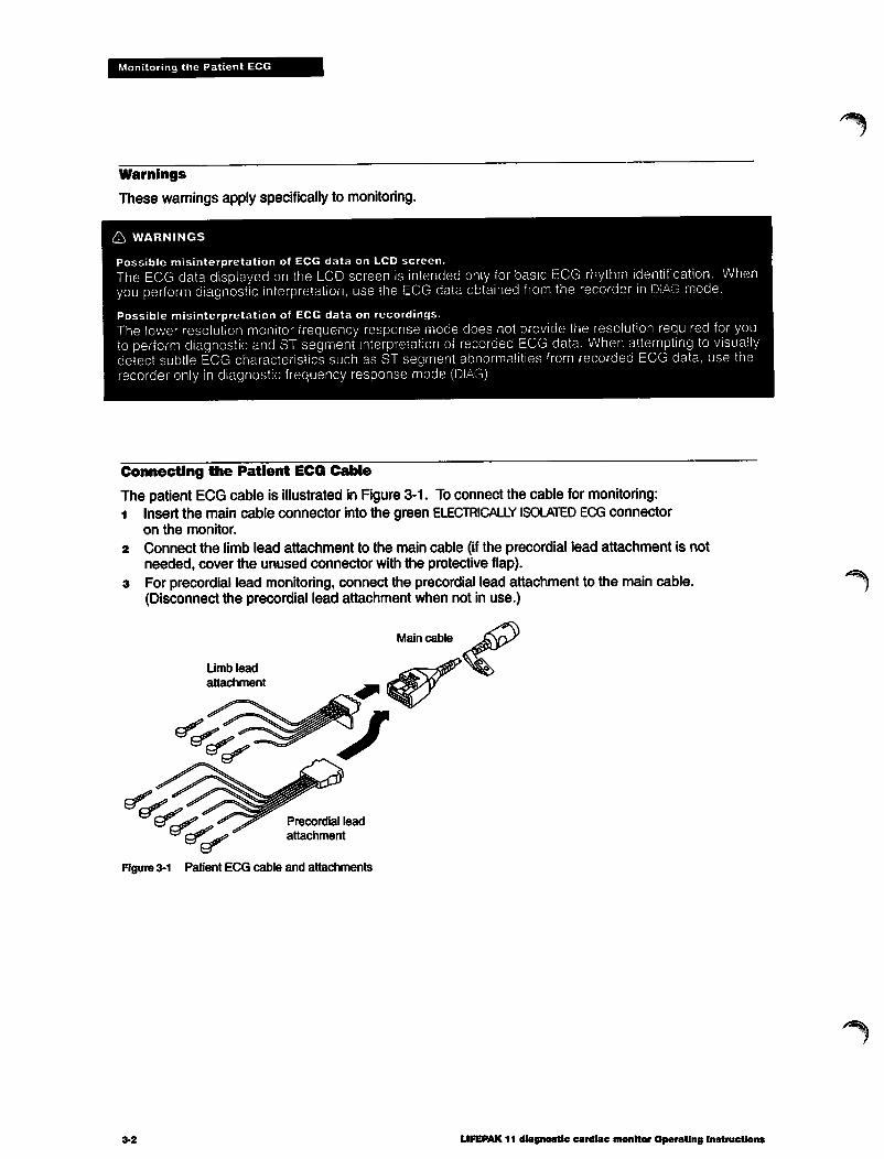
The patient ECG cable is illustrated in Figure3-1. Toconnect the cable for monitoring:1 Insert the main cable connector into the green ELECTRICALLY ISOLATED ECG connector
on the monitor.
2 Connect the limb lead attachment to the main cable (if the precordial lead attachment is notneeded, cover the unused connector with the protective flap).
3 For precordial lead monitoring, connect the precordial lead attachment to the main cable.(Disconnect the precordial lead attachment when not in use.)
Limb lead
attachment
Precordial lead
attachment
Figure 3-1 Patient ECG cable and attachments
3*2
Main cable
LIFEPAK 11 diagnostic cardiac monitor Operating Instructions

j?Pn
Monitoring the Patient ECG
ECG Monitoring Procedure
Limb Lead Monitoring
To perform limb lead ECG monitoring:1 Turn the POWER switch to BATT and adjust CONTRAST as needed.2 Make sure the main cable and limb lead attachment are connected as shown in Figure 3-13 Identify the appropriate electrodes sites on the patient as shown in Figure 3-2.
AHA Labels
RA Right ArmLA Left Arm
RL Right LegLL Left Leg
Figure 3-2 Limb lead electrode placement
IEC LabelsR RightL Left
N NegativeF Foot
Prepare patient's skin for electrode application:• Shave excessive hair at electrode site. Avoid locating electrodes over tendons and major
muscle masses.
• For oily skin, clean skin with alcohol pad.• Dry site with brisk rub.Apply ECG electrodes:• Inspect electrode package and confirm package is sealed and date is not expired. Carefully
tear open foil package and remove electrode carrier.• Attach an electrode to each of the lead wires.
• Grasp electrode tab and peel electrode from carrier.• Inspect electrode gel and make sure gel is intact (discard electrode if gel is not intact).• Hold electrode taut with both hands. Apply the electrode flat to the skin. Smooth tape
outwardly in all directions. Do not press the center of the electrode.• Secure the cable with the cable clasp.Press LEAD SELECT to select desired limb lead (leads I, II, III, aVR, aVL, and aVF are available).Adjust ECGSIZE if necessary. Size is automatically set to gain of X1.0 at power-on. To properlycount heart rate during routine monitoring, the ECG size may need to be adjusted as follows:
• Press VOL A until the QRS complexesare audible.• Press ECG SIZE V or A until the systole beeper coincideswith every QRS complex.• Adjust VOL V or A as desired.Secure the ECG cable with the cable clasp.To obtain a recorded ECG report, press RECORD to activate the recorder and store the report.Press RECORD again or press EXIT to stop the recorder. Refer to page 5-4 for a completedescription of ECG recording.
LIFEPAK 11 diagnostic cardiac monitor Operating Instructions°April 1996. Physio-Control Corporation
3.3

Monitoring the Patient ECG
Precordial Lead Monitoring
The precordial (chest) leads (V1 through V6 for AHA, or C1 through C6 for IEC) are available formonitoring when the precordial lead attachment is connected to the main cable. To performprecordial lead ECG monitoring:1 Insert the precordial lead attachment into the main cable as shown in Figure 3-1.2 Follow the steps listed for limb lead monitoring beginning on page 3-3. Place the precordial lead
electrodes on the chest as shown in Figure 4-3.
Paddles Lead Monitoring
When using theLIFEPAK 11 monitor with a compatible defibrillator, patient ECG canbe monitoredin PADDLES lead using the QUIK-LOOK paddle feature or by applying QUIK-COMBO electrodes.Refer to Operating Instructions for the PADDLES lead monitoring procedures.
Color Coding for ECG Leads
The lead wires and the electrode snaps for the patient ECG cable are color-coded according toAHA or IEC standards as listed in Table 3-1.
Table 3-1 ECG leads color codes
Limb Leads
Precordial Leads
AHA Label AHA Color
RA White
LA Black
RL Green
LL Red
V1 Red
V2 Yellow
V3 Green
V4 Blue
V5 OrangeV6 Violet
IEC Label IEC Color
R Red
L Yellow
N Black
F Green
C1 Red
C2 Yellow
C3 Green
C4 Brown
C5 Black
C6 Violet
ECG Electrode Requirements
Electrode quality is critical for obtaining an undistorted ECG signal. Alwayscheck the date code onelectrode packages for expiration date before patient use. Do not use electrodes withexpired datecodes. The disposable electrodes are intended for a single use; do not reuse disposable electrodes.
For best ECG monitoring results, use silver/silver chloride (Ag/AgCI) electrodes such asPhysio-Control LIFE»PATCH® ECG electrodes. Post-defibrillation display of ECG on the screen isfaster using silver/silver chloride electrodes than with other electrode types.
3-4 LIFEPAK 11 diagnostic cardiac monitor Operating Instructions

•j|iP\
Monitoring the Patient ECG
Leads Off Messages During Monitoring
If an ECG lead electrode disconnects during monitoring, the monitor emitsan audible alarm anddisplays a leads off message. For example, if the RA lead electrode disconnects while monitoringin lead II, the monitor displays the CONNECT LEADS message and the flashing RA LEADS OFFmessage as shown below:
HR
LEAD II
X1.0
CONNECT LEADS
RA LEADS OFF12:14:38
The monitor continues to flash the RA LEADS OFF message and periodically emit three beeps untilyou reconnect the RA lead electrode or turn POWER to OFF.
If two or three electrodes disconnect, the monitordisplays the electrode names (such as LA RALEADS OFF). If more than three electrodes disconnect, the message is ECG LEADS OFF
The RLelectrode does not have the abilityto sense a (dis)connection. Ifthe RL electrodedisconnects during monitoring, a leads-off message does not appear. However, the qualityof theECG trace may be affected.
Monitoring Patients with Internal Pacemakers
The LIFEPAK 11 monitor typically does not use internal pacemaker pulses to calculate heart rate.However, when using the QUIK-COMBO electrodes or standard paddles to monitor in PADDLESlead, the monitor may detect internal pacemaker pulses as QRS complexes. This may result in aninaccurate heart rate display.
Large amplitude pacemaker spikes can overload the QRS complex detector circuitry so that nopaced QRS complexes are counted. To help minimize ECG pickup of large unipolar pacemakerpulses when monitoring patients with internal pacemakers, place ECG electrodes so the linebetween the positive and negative electrodes is perpendicular to the line between the pacemakergenerator and the heart.
Smaller amplitude internal pacemaker pulses may not be distinguished clearly in PADDLES lead.For greater visibility of internal pacemaker pulses, use agency or diagnostic mode frequencyresponse.
LIFEPAK 11 diagnostic cardiac monitor Operating Instructions'April 1996, Physio-Control Corporation
3-5

Monitoring the Patient ECG
Troubleshooting Tips for ECG Monitoring
If problems occur whilemonitoring, check the listof observations inTable 3-2 for aid introubleshooting. For basic troubleshooting problems such as no power, refer to Troubleshootingonpage 9-18.
Table 3-2 Troubleshooting tips for ECG monitoringObservation
Monitor screen displayblank with POWER on.
Any of these messagesdisplayed:CONNECT LEADS
CONNECT ECG LEADS
ECG LEADS OFF
xx LEADS OFF
Possible Cause
CONTRAST needsadjustment.
Monitor battery low.
Screen not functioningproperly.
One or more ECGelectrodes disconnected.
ECG cable is not connectedto monitor.
Poor electrode-to-patientadhesion.
Broken lead wire.
Poor ECG signal quality. Poor electrode-skin contact.
Outdated, corroded, ordried-out electrodes.
Loose connection.
Damaged cable orconnector/leadwire.
Noise because of radio
frequency interference(RFI).
Corrective Action
Adjust CONTRAST.
Replace with fully-charged battery.
Print ECG data on recorder as backupand contact service personnel for repair.
Confirm ECG electrode connections.
Confirm cable connections.
Reposition cable and/or lead wires toprevent electrodes from pulling awayfrom patient.Prepare skin per page 3-3 and replaceelectrode(s).
Press LEAD SELECT to monitor another
lead.
Select PADDLES lead and use standard
paddles or QUIK-COMBO electrodes forECG monitoring.Check cable continuity.
Reposition cable and/or lead wires toprevent electrodes from pulling awayfrom patient.Prepare skin per page 3-3 and replaceelectrode(s).
Check date codes on electrodepackages.Use only unexpired silver/silver chlorideelectrodes. Leave electrodes in sealed
pouch until time of use.
Check/reconnect cable connections.
Inspect main cable and attachments.Replace ifdamaged.Test cable with simulator and replace ifmalfunction observed.
Check for equipment causing RFI(such as a radio transmitter) and relocateor turn off equipment power.
3.6 LIFEPAK 11 diagnostic cardiac monitor Operating Instructions

Table3-2 Troubleshooting tips for ECG monitoring, continuedObservation
Baseline wander (lowfrequency/high amplitudeartifact).
Fine baseline artifact (highfrequency/low amplitudeartifact).
Possible Cause
Inadequate skinpreparation.
Poor RL electrode-skincontact.
Inadequate skinpreparation.
Isometric muscle tension in
arms/legs.
RL electrode disconnect.
6 Systole beeps not heard. Volumetoo low.
Systole beeps do not occurwith each QRS complex.
Monitor displays flatlineECG trace with no
CONNECT LEADS message.
Heart rate (HR) displaydifferent than pulse rate.
QRS amplitude too small todetect.
PADDLES lead displayed butpatient connected throughECG cable.
ECG size set too high ortoo low.
Monitor detecting thepatient's internalpacemaker pulses.
LIFEPAK 11 diagnostic cardiac monitor Operating Instructions°April 1996. Physio-Control Corporation
Monitoring the Patient ECG
Corrective Action
• Prepare skin as described on page 3-3and reapply electrodes.
• Check RL and other electrodes forproper adhesion.
• Prepare skin as described on page 3-3and reapply electrodes.
• Confirm that limbs are resting on asupportive surface.
• Check RL and other electrodes forproper adhesion.
Press VOL up until systole beeps can beheard.
• Adjust ECG SIZE until beeps occur witheach QRS complex.
• Press LEAD SELECTto display one of thelimb or precordial leads.
• Adjust ECG size up or down.
• Change monitor lead or reduce ECGsize.
3-7

ACQUIRING A 12-LEAD ECG
F^ This section describes how to acquire a 12-Lead ECG, including:
12-Lead ECG Procedure page 4-2
Identifying 12-Lead Electrode Sites 4-3
Screen Messages during 12-Lead ECG 4-5Description of Printed 12-Lead ECG Report 4-6
Computerized ECG Analysis 4-8
Troubleshooting Tips for Acquiring a 12-Lead ECG 4-12
LIFEPAK 11 diagnostic cardiac monitor Operating Instructions 4-1cApril 1996. Physio-Control Corporation

Acquiring a 12-Lead ECG
12-Lead ECG Procedure
To acquire a 12-Lead ECG:
1 Turn the POWER switch to BATT and adjust CONTRAST as needed.2 Insert the limb leadand the precordial lead attachments into the main cableas shown in
Figure 4-1.
Limb lead
attachment
Precordial lead
attachment
protective flap(open)
Figure 4-1 12-Lead ECG attachments for patient ECG cable
3 Insert the main cable connector into the green ELECTRICALLY ISOLATED ECG connector on themonitor.
4 Identify the appropriate electrodes sites on the patient as described on page 4-3.5 Prepare patient's skin for electrode application:
• Shave excessive hair at electrode site. Avoid locating electrodes over tendons and majormuscle masses.
• For oily skin, clean skin with alcohol pad.• Prepare site with brisk rub.
& WARNING Possible inability to obtain diagnostic-quality 12-Lead ECG reports
Do not use previously unpackaged electrodes or electrodes with expired date codes. Such electrodesmay impair signal quality. Use only electrodes removed from a sealed package immediately beforeuse and follow the procedure for electrode application.
Apply ECG electrodes:• Inspect electrode package and confirm package is sealed and date is not expired.
Carefully tear open foil package and remove electrode carrier.• Attach an electrode to each of the 10 lead wires.
• Grasp electrode tab and peel electrode from carrier.• Inspect electrode gel and make sure gel is intact (discard electrode ifgel is not intact).• Hold electrode taut with both hands. Apply the electrode flat to the skin. Smooth tape outwardly
in all directions. Do not press the center of the electrode.• Secure the cable with the cable clasp.
4-2 LIFEPAK 11 diagnostic cardiac monitor Operating Instructions

jp^
#^
Acquiring a 12-Lead ECG
7 Encourage the patient to remain as still as possible, and provide support as needed.8 Press 12 LEAD once to acquire and printthe 12-Lead ECG report. Observe the status messages in
the upper left corner of the monitor screen:
9 If the monitor detects signal noise (such as patient motion or a disconnected electrode), the12-lead acquisition is interrupted until noise is removed. Take appropriate action as required (suchas reconnecting leads). Troubleshooting tips are provided on page 4-12.
Press EXIT to stop the 12-lead ECG acquisition.
Identifying 12-Lead Electrode Sites
Limb Lead Electrode Sites
When acquiring a 12-Lead ECG report, limb lead electrodes are typically placed on the wrists andankles as shown in Figure 4-2. The limb lead electrodes can be placed anywhere along the limbs.However, do not place the limb lead electrodes on the torso when acquiringa 12-Lead ECG report.
RA/R
RL/N
LA/L
LL/F
AHA Labels
RA Right ArmLA Left Arm
RL Right LegLL Left Leg
Figure4-2 Limblead electrode placement for 12-lead ECG
LIFEPAK 11 diagnostic cardiac monitor Operating Instructions0April 1996, Physio-Control Corporation
IEC Labels
R RightL Left
N NegativeF Foot
4-3

Acquiring a 12-Lead ECG
Precordial Lead Electrode Sites
The six precordial (chest) leads are placed on specific locations as shown in Figure 4-3 andsummarized in Table 4-1. Proper placement is important for accurate diagnosis and should beidentifiedas follows (leads are V1 through V6 for AHA, or C1 through C6for IEC; refer to Table 3-1 onpage 3-4 for color codes):
Angle of Louis
Figure 4-3 Precordial lead electrode placement
Table 4-1 Precordial lead electrode placement
V1 C1 Fourth intercostal space to the right of the sternum.
V2 C2 Fourth intercostal space to the left of the sternum.
V3 C3 Directly between leads V2and V4.
V4 C4 Fifth intercostal space at midclavicular line.
V5 C5 Level with V4at left anterior axillary line.V6 C6 Level with V5 at left midaxillary line
(directly under the midpoint of the armpit).
Locating the V1 position (fourth intercostal space) is critically important because it is the referencepoint for locating the placement of the remaining Vleads. To locate the V1 position:1 Place your finger at the notch in the top of the sternum.2 Moveyour finger slowly downward about 1.5 inches (3.8 centimeters) until you feel a slight
horizontal ridge or elevation. This is the "angle of Louis" where the manubrium joins the body ofthe sternum.
3 Locate the second intercostal space on the right side, lateral to and just below the angle of Louis.4 Move your finger down two more intercostal spaces to the fourth intercostal space which is the V1
position.
Other important considerations:
• When placing electrodes on female patients, always place leads V3-V6 under the breast ratherthan on the breast.
• Never use the nipples as reference points for locating the electrodes for men or women patientsbecause nipple locations may vary widely.
LIFEPAK 11 diagnostic cardiac monitor Operating Instructions
/^^Sk

Acquiring a 12-Lead ECG
Screen Messages During 12-Lead ECG
The typical sequence of screen messages that are displayed after you press 12LEAD is:ACQUIRING 12-LEAD #x
ANALYZING 12-LEAD #x
STORING 12-LEAD #x
PRINTING 12-LEAD #x
Each message is displayed in sequence for a few seconds while the monitor performs theassociated activity ("x" is the number of the report).
Data Acquisition Mode
The monitor acquires 10 seconds of ECG data for each 12-lead ECG requested. The monitor canbe configured to analyze the 10 seconds of data before you press 12 LEAD (the PRE option) or 10seconds of data after you press 12 LEAD (the POST option).
If you configure the monitor for the PRE option, the message ACQUIRING 12-LEAD #x does not appearbecause the data is already acquired when you press 12 LEAD. For information about configuringthis mode, refer to page 10-6.
ECG Override
To acquire a 12-lead ECG, the monitor must collect 10 seconds of undistorted data. If the monitordetects signal noise while acquiring data (such as patient motion or a disconnected electrode), themonitor displays the message WAITING FOR GOOD DATA. The monitor displays this message as longas signal noise is detected. When signal noise is eliminated, the monitor removes the messageand resumes acquiring data.
While the monitor displays the message WAITING FOR GOOD DATA, you can choose to press 12 LEADagain and force the monitor to acquire the 12-Lead ECG report regardless of detected signal noiseor disconnected leads. Any 12-Lead ECG reports acquired in this way are annotated with thefollowing message:
***ECG OVERRIDE: DATA QUALITY PROHIBITS INTERPRETATION*"
No interpretation or justification information is printed on this type of 12-Lead ECG report.
LIFEPAK 11 diagnostic cardiac monitor Operating Instructions0April 1996, Physio-Control Corporation

Acquiring a 12-Lead ECG
Description off Printed 12-Lead ECG Report
The monitorcan be configured to printthe 12-Lead ECG report in a 3-channel or a 4-channel format.
To protect recorder printouts after printing:• Avoid extended exposure to direct sunlight• Do not store in plastic folders (use paper only)• Do not apply tape or adhesives to the printed side.
The 3'Channel Format
Figure 4-4 presents an example of a 12-Lead ECG report printed in the 3-channel format thatincludes 2.5 seconds of data from each of the 12 leads. The sequence of leads for the 3-channelformat is always printed in the order shown. 12-Lead ECG reports are always acquired and printedin diagnostic frequency response. The 12-Lead ECG reports can be reprinted in monitor frequencyresponse if desired.
The computerized ECG analysis statements shown in the upper right corner of Figure 4-4 aredescribed on page 4-8.
Report typeand sequencenumber
Patient ID Time/dateof recording
Standardmeasurements
^Computerized ECG analysis
Name:JOHNCLAYTON•ID#:052094051417 j112-Lead #1
HR:84."vr;
SINUS RHYTHM1 nri:<w r-urid-i axes: az na -zo i i. sinus rirmriivi
toe:78j >8ex:M /!fPRtntf200 QRS DunlOOr QT/QTc:i388/423 IPpSSIBLELErTATRIALENURGEMENT05/20/94x05:18:2fi — f~ "T""""~^-^——-^^— |ANTERIOR EPICARDlAL INJURY
ACUTE Ml SUSPECTED"* ^UNCQNF
ECG Frequency Recorder Leadsize response speed annotation
1mV reference pulse
Figure 4-4 Example of printed 3-channel 12-Lead ECG report
4-6
Device* Site# Monitor Model,software serial
version number
LIFEPAK 11 diagnostic cardiac monitor Operating Instructions

f^
Acquiring a 12-Lead ECG
As shown in Figure 4-5, the monitor acquires and analyzes 10 seconds of data for all 12 leads, thenprints 2.5-second portions for each lead.
Figure 4-5 12-Lead ECGdata portionsprintedin3-channel format
LIFEPAK 11 diagnostic cardiac monitor Operating InstructionsoApril1996, Physio-ControlCorporation

Acquiring a 12-Lead ECG
The 4-Channel Format
Figure 4-6 presents an example of a 12-lead ECG report printed in the 4-channel format.The 4-channel format consists of the median complex (or "median beaf) derived for each of the 12leads and 10 seconds of data for Lead II. For a description of how the monitor derives the medianbeat, refer to page 4-10.
KUL
Name: JOHN CLAYTONID#:052094051417 !12-Lead #1
Age:7805/20/34
SINUS RHYTHMJPOSSIBLE LEFT ATRIAL ENLARGEMENTANTERIOR EPICARDIALINJURY'"ACUTE MlSUSPECTED*" "UNCONFIRMED*
Sex:M ;05:18:23
HR:84 P-QRS-T axes: 52 15 -26PR Iht: 200 QRS jDur: 100 QT/QTc: 388/429
x1.0 .05-150HZ 25mm/s Comments: CP WOKE HIM 04 001 X.X LPK1134
Figure 4-6 Example of printed 4-channel 12-Lead ECG report
If the printer speed is set to 50mm/s for report reprints in the 4-channel format, the median beatsare printed at 50mm/s, but the Lead II data is printed at the bottom at 25mm/s.
Computerized ECG Analysis
Computerized ECG analysis statements are available for printingon LIFEPAK 11 monitor 12-LeadECG reports. The following pages present a brief description. For more information, refer to thePhysician's Guide to Computerized ECG Analysis.
There are three possible types of information:• Interpretation statements• Justification statements (printed in brackets)• The ***ACUTE Ml SUSPECTED*** message.
Figure 4-7 shows a sample portion of a 12-Lead ECG report with all three types of information.
Interpretation statements
SINUS BRADYCARDIA WITH SINUS ARRHYTHMIAINFERIOR INFARCT [40+ MSQWAVE AND/OR ST/T ABNORMALITY INII/AVF1, POSSIBLY ACUTEST&T WAVE ABNORMALITY, POSSIBLE LATERAL ISCHEMIA [-0.1+ MV TWAVEINI/AVL/V5/V61"•ACUTE Ml SUSPECTED*" "UNCONFIRMED"
Acute Ml Suspected message
Figure 4-7 Computerized ECG analysis statements
Justification statements
(printed in brackets)
LIFEPAK 11 diagnostic cardiac monitor Operating Instructions

Acquiring a 12-Lead ECG
The monitor is configured to allow printing of interpretation statements and the ACUTE Ml message,and to inhibit printing of justification statements. To reconfigure printing options, refer to page 10-6.
Patient Treatment and Computerized ECG Analysis
Computerized ECG analysis should not be used to withhold or prescribe patient treatment withoutreview by qualified medical personnel. All 12-Lead ECG interpretation statements provided by theLIFEPAK 11 monitor include the printed message "UNCONFIRMED**.
Interpretation Statements
The interpretation statements are classified in accordance with the Tenth Bethesda Conference onOptimal ECG. There are three categories of statements as shown in Table 4-2.
Table 4-2 Categories of 12-lead ECG interpretation statements
Category Description Examples
A
~c~
Diagnosis of an anatomic lesion or pathophysiologic state • ANTERIOR INFARCT• RIGHT VENTRICULAR HYPERTROPHY
Diagnosis of electrophysiologic changes*
Descriptive ECG features
• ATRIAL FIBRILLATION
• RIGHT BUNDLE BRANCH BLOCK
• NONSPECIFIC T WAVE ABNORMALITIES
• LONG QT INTERVAL
* Ventricular Tachycardia and VentricularFibrillation are not among the diagnostic statements available bycomputerized ECG analysis.
Justification Statements
The justification statements explain the basis for the interpretationstatements. The justificationstatements indicate the criteria met by the patient ECG data during computerized analysis.
Table 4-3 provides two examples of interpretation statements and corresponding justificationstatements. For a complete listing and explanation of interpretation and justification statements,refer to the Physician's Guide to Computerized ECG Analysis.
Table 4-3 ECG criteria for justification and interpretation statements
Interpretation Statement
ANTERIOR INFARCT
T WAVE ABNORMALITY,CONSISTENT WITH INFERIORISCHEMIA
Justification Statement
[40+ MS Q WAVE AND/OR ST/TABNORMALITY IN V3/V4]
1-0.5+ MV TWAVE IN ll/AVF]
LIFEPAK 11 diagnostic cardiac monitor Operating Instructions°April 1996, Physio-Control Corporation

Acquiring a 12-Lead ECG
The ***Acute Ml Suspected*** Message
The LIFEPAK 11 monitor prints the message ***ACUTE Ml SUSPECTED*** when patient data meetcertain ECG criteria associated with Acute Myocardial Infarction (AMI). Conventional 12-leadinterpretive algorithms depend primarily on the presence of pathologic Q waves to detect AMI.However, other electrophysiologic changes such as localized ST-segment elevation and T-waveabnormality often appear in the early evolution of AMI before pathologic Q waves are present.Unless conventional algorithms are modified to includethese other changes often present in theacute phase, AMI is not detected in its very early stages.
The computerized ECG analysis for the LIFEPAK 11 monitor includes ST-segment elevation andT-wave abnormalities among the decision criteria for AMI. This expanded ECG criteria increasesthe capability for early AMI detection for the LIFEPAK 11 monitor.
Deriving the Median Beat
The interpretation statements pertaining to myocardial injury, infarct, and ischemia are derived frommeasurements made on a signal-averaged beat (median beat) formed for each of the 12 leads.The computerized ECG analysis selects three representative beats from the ten seconds of data foreach lead and averages the three beats to derive the median beat for that lead.
Figure 4-8 illustrates this signal-averaging as applied to lead V3. The median beats used foranalysis are printed in the 4-channel format of the 12-Lead ECG report. In the example inFigure 4-8, the monitor detects ST-segment elevation which meets the criteria for printing themessage ***ACUTE Ml SUSPECTED*** in the interpretation statements.
4-10 LIFEPAK 11 diagnostic cardiac monitor Operating Instructions

X1.0 .05-15CHz25mm/s Comments: CP WOKE HIM
Acquiring a 12-Lead ECG
ST segment elevationmeets criteria for
***ACUTE Ml SUSPECTED***
Name: jr/JJCLAYTON HR:84 P-QRS-tID#:05'A4051417 Age: 78 Sex:M PR Int: 200 QRS Durl\l-Wm 05/20/94 05:18:23
SINUS RHYTHMPOSSIBLE LEFT ATRIAL ENLARGEMENTANTERIOR EPICARDIAL INJURY'"ACUTE Ml SUSPECTED"* "UNCONFIRMED*
04 001 X.X LPK1134
4-channel format
Figure4-8 Deriving the median beat
LIFEPAK 11 diagnostic cardiac monitor Operating Instructions°April 1996, Physio-Control Corporation
4-11

Acquiring a 12-Lead ECG
Troubleshooting Tips for Acquiring a 12-Lead ECG
Ifproblems occur while acquiring a 12-Lead ECG report, check the list of observations in Table 4-4.For basic troubleshooting problems such as no power, refer to Troubleshooting on page 9-15.
Table 4-4 Troubleshooting tips tor 12-Lead ECG
Observation
Any of these messagesdisplayed:CONNECT LEADS
CONNECT ECG LEADS
ECG LEADS OFF
xx LEADS OFF
2 Noisy signal and/or messagedisplayed:WAITING FOR GOOD DATA.
WAITING FOR GOOD DATA
may be caused by noise ina lead(s) other than thedisplayed lead. Toinvestigate, press 12 LEADagain to override themessage. Examine theprintout to determine whichlead(s) is affected by noise.Replace or reposition theaffected electrode(s) andlead wire(s).
Recorder paper jams, slips,misfeeds, or print quality ispoor.
Monitor does not complete12-lead ECG operationsequence.
Possible Cause
One or more ECG
electrodes disconnected.
ECG cable is not
connected to monitor.
Poor electrode-to-patientadhesion.
Broken lead wire.
Poor electrode-skin
contact.
Loose connection.
Patient motion.
Vehicle motion.
Outdated, corroded, ordried-out electrodes.
Radio FrequencyInterference (RFI).
Damaged cableor connector.
Recorder malfunction.
Operator pressedanother function button(such as RECORD)before 12-lead ECGsequence completed.
Corrective Action
Confirm ECG electrode connections.
Confirm cable connections.
Reposition cable and/or lead wires toprevent electrodes from pulling awayfrom patient.Prepare skin per page 4-2 and replaceelectrode(s).
Check cable continuity.
Reposition cable and/or lead wires toprevent electrodes from pulling awayfrom patient.Prepare skin per page 4-2 and replaceelectrode(s) if necessary.
Check/reconnect cable connections.
Encourage patient to lie quietly.
Stop vehicle while acquiring 12-leadECG data (may resume transport whenSTORING 12-LEAD #x message appears).
Check date codes on electrodepackages.Use only unexpired silver/silver chlorideelectrodes; leave electrodes in sealedpouch until time of use.
Check for equipment causing RFI (suchas a radio transmitter) and relocate orturn off equipment power.
Inspect main cable and attachments.Press LEAD SELECT to display eachavailable lead and check for presence ofECG signal in each lead. Replace cableifdamage or malfunction discovered.
Reprint the report from the directory.Refer to Troubleshooting Tips forRecording, page 5-9.
• Press 12 LEAD to acquire another12-lead ECG. Allow enough time forsequence to complete.
LIFEPAK 11 diagnostic cardiac monitor Operating Instructions

Table 4-4 Troubleshooting tips for 12-Lead ECG, continued
Observation
s Baseline wander (lowfrequency/high amplitudeartifact).
6 Fine baseline artifact (highfrequency/low amplitudeartifact).
Possible Cause
Inadequate skinpreparation.
Poor RL electrode-skin
contact.
Inadequate skinpreparation.
Isometric muscle tension
in arms/legs.
RL electrode disconnect.
LIFEPAK 11 diagnostic cardiac monitor Operating Instructions0April 1996, Physio-Control Corporation
Acquiring a 12-Lead ECG
Corrective Action
• Prepare skin as described on page 4-2and reapply electrodes.
• Check RL and other electrodes for
proper adhesion.
• Prepare skin as described on page 4-2and reapply electrodes.
• Confirm that limbs are resting on asupportive surface.
• Check RL and other electrodes for
proper adhesion.
4-13

jfPy
CREATING PATIENT REPORTS
This section describes how to create patient reports. Topics include:
Patient Report Types page 5-2Entering the Patient ID 5-2
Activating the Recorder 5-4
Marking Events with Event Keys 5-6Printing the CODE SUMMARY Report 5-7Troubleshooting Tips for Recording 5-9
LIFEPAK 11 diagnostic cardiac monitor Operating Instructions 5>1°April 1996, Physio-Control Corporation

Creating Patients Reports
Patient Report types
The LIFEPAK 11 monitor generates five types of patient reports:
CODE SUMMARY™
Recorded ECG
12-LEAD ECG
Defibrillation
Pacing Event
This is a summary report that the monitor software creates foreach patient. This summary may include some or all of thefollowing:• Patient Identification Data
• Event Log• Recorded ECG Report• 12-Lead ECG Report• Defibrillation Report• Pacing Event Report
An example of the Code Summary report is shown in detail inFigure 5-4.
This report is a recording of the displayed ECG and of datacollected by two other leads during monitoring. Refer to Figure 5-1on page 5-4.
This diagnostic report is described in Section 4, "Acquiring a12-lead ECG." Refer to Figure 4-4.This ECG report is annotated with the JOULES SELECTEDmeasurement and SYNC ON if synchronized cardioversion isselected. It is automaticallygenerated and stored when energy isdischarged. Refer to Figure 8-3.This ECG report is annotated with the pace rate, pace current, andpace mode. It is automatically generated and stored at the onsetof pacing and when pacing is set, changed, or stopped. Refer toFigure 8-4.
Entering the Patient ID
When you connect the ECG electrodes to the patient after applying power to the monitor, themonitordisplays the Home screen. The Home screen is the background screen that is displayedduring ECG monitoring:
5-2 LIFEPAK 11 diagnostic cardiac monitor Operating Instructions

Creating Patients Reports
When the Home screen first appears at power-on, no patient name or identification (ID) number isdisplayed. To enter patient data:1 Press the PATIENT ID softkey. The Patient ID screen is displayed with the Patient ID field in the
upper left corner:
2 Usethe alphanumeric keypad to enter the name, ID, age, and sex. Press the ENT key or the V orA softkeysto movethrough the fields. After advancing past the SEX: field, the COMMENTS: field isdisplayed:
After entering patient data, press EXIT to return to the Home screen. The Home screen nowincludes the last name of the patient (CARVER in this example):
PATIENT: CARVER
The monitor assigns each new patient a unique ID composed of the date and time power isapplied, such as ID#:062594084614 on the next page. You can change this ID on the Patient IDscreen ifyou desire; however, it may be helpful to leave the original ID unchanged for ease intracking patients.
You can configure the monitor to display the ID (such as PATIENT: 062594084614) rather than the lastname. Refer to the PRIMARY FILE IDENTIFIER in the Startup Defaults, page 10-7.
You can configure the monitor to disable the Patient ID screen and prevent editing of the ID. In thiscase, the PATIENT ID softkey and patient name are not displayed on the Home screen. Each patientis identified only by the unique ID assigned by the monitor. Refer to PATIENT ID SCREEN AVAILABLE? inthe Device Features, page 10-6.
LIFEPAK 11 diagnostic cardiac monitor Operating Instructions"April 1996, PhyskvControl Corporation
5-3

Creating Patients Reports
Activating the Recorder
To initiate a recorded ECG report:1 Press RECORD. This activates the recorder and causes the monitor to store a recorded ECG report
in memory.2 To stop the recorder, press RECORD again or press EXIT.
Recorded ECG Report
The recorded ECG report is shown and described in Figure 5-1. The printed report includes ECGdata and patient data from the Patient ID field.
1 mV
reference
pulse
Patient ID , Report typeand sequencenumber
Name: GEORGE CARVER / HR:58ID#: 062594084614/ Age:48 /Sex:MRecorded ECG #1' 06/25/94 ' 09:12:37
Time of
recording
-^-JU-^—mU^^-aJL^—''wL^—ajL^~—^-JL*°—aJL^->—,
Lead ECG Frequency Recorder Device # Site# Monitor Monitorannotation size response speed software
version
model and
serial number
Figure 5-1 Recorded ECG report example
The recorded ECG report stored in memory consists of eight seconds of data: three secondsbefore you press RECORD, and five seconds after.
To protect recorder printouts after printing:• Avoid extended exposure to direct sunlight.• Do not store in plastic folders (use paper only).• Do not apply tape or adhesives over tracings or annotations.
5-4 LIFEPAK 11 diagnostic cardiac monitor Operating Instructions
/*%

Creating Patients Reports
Recording Screen
While storing the recorded ECG report in memory, the monitor displays the Recording screen withthe message STORING RECORDED ECG #x in the upper left corner (x is the report sequence number):
STORING RECORDED ECG »1
PATIENT: CARVER
08:52:17
HR66LEAD II
X1.0
After storing the report, the monitor displays the recorder status message RECORDING.The recorder continues to print until you press RECORD or EXIT.
The three softkeyson the Recording screen allow you to change the current printing format (theydonot change the content or format of the recorded ECG reportstored in memory):
LEAD GROUP Selects which group of three leads is printed as described in the nextparagraph.
MONITOR Selects frequency response for the printed strip. Pressing softkey changes toMONITOR (1.0-30Hz) or DIAG (diagnostic, 0.05-150Hz).
SPEED 25MM/S Changes recorder speed (5,10, 25, or 50mm/s).
If recording in PADDLES lead, the printed frequency response is always 2.2-30Hz and the MONITORsoftkey is not displayed.
Lead Group
Each of the twelve possible leads is associated with two other leads in a "lead group." There aresix possible lead groups:• Default lead group (you can define)• PADDLES (only the paddles lead is printed ifselected)• I, II, III. aVR, aVL, aVF• V1,V2, V3• V4.V5.V6
Whenthe recorded ECG report is stored in memory and printed, ECG data is stored and printed forthe displayed lead and the other two leads in the associated lead group. Forexample, Lead II isdisplayed in the screens on page 5-2. After you press RECORD, the recorder prints the data asshown in Figure 5-1 which includes rhythms for Leads I, II, and III. This is the lead groupassociated with Lead II.
Although five of the lead groups are predefined (such as Leads I, II, III above), you can configureany three of the 12 leads to be the default lead group. The default lead group is always printed ifthe lead displayed at the time you press RECORD is included in the default lead group. Refer toDefault Printer Lead Group on page 10-10 for more information.
LIFEPAK 11 diagnostic cardiac monitor Operating Instructions°April1996. Physio-ControlCorporation
5.5

Creating Patients Reports
Marking Events with Event Keys
During patient care you may use the alphanumeric keys as "eventkeys" to mark important eventsintothe CODE SUMMARY report. Typical events may be the administration of drugs or othertherapies. The event keys are predefined through the Event Key Definitions option described onpage 10-10.
For example, Figure 5-2 shows a monitor with 10 event keys defined. The operator has written theevent key definitionsonto the erasable label under the keypad cover for quick reference.
Figure 5-2 Event key definitions
EVENT KEY DEFINITIONS
KEY EVENT KEY EVENT
A Atropine B Bretvlium
C CPR E EpinephrineI Intubate L Lidocaine
0 Oxygen P ProcainamideV Verapamil X Event Mark
v.
Alphanumeric keys
Marking the Event
To mark an event:
1 Lift up the keypad cover to access the keypad.2 Confirm the monitor is displayingthe Home screen (or press EXIT to return to the Home screen).3 Press the desired event key. The monitor displays the Event Keyscreen as shown in Figure 5-3.4 Press ENT to mark or store the event into the patient's CODE SUMMARY report. The Home
screen reappears.
For example, an operator using the monitorshown in Figure 5-2 can press the event key O foroxygen after administering oxygen. The monitor displays the Event Key screen as shown inFigure 5-3. The operator presses ENT to store the event in the patient's CODE SUMMARY report.When the CODE SUMMARY report is printed, the oxygen and time administered are listed as oneof the events.
5-6 LIFEPAK 11 diagnostic cardiac monitor Operating Instructions

Jfp\
When the operator presses Othe event description appears
After the operator pressesENT, the event is listed in theCODE SUMMARY Event Log,
Name: GEORGE CARVER \' • 'IM:01089101073C I Age:CODESUMMARY™ 06/25/94CRITICAL EVENTRECORDPower On: -I --• 1259:11Total ShocksTotal Time Paced: . ; 00:00:00Total 12-Leads: I ; . 1L _Elapsed Time: ! r 00:07:29Device #:StteR
Comments:
r2TV238
Creating Patients Reports
CODE SUMMARY Report
Figure 5-3 Event Key screen and CODE SUMMARY report
After you press the event key, the monitor displays the Event Key screen until you press ENT tostore the event or cancel the event by pressing another key or button. Ifyou do not press ENT,the event is not stored. After an event is stored, it cannot be removed from theCODE SUMMARY report.
Other Operations and Event Keys
Event keys cannot be used while another operation is underway such as operating the recorder,acquiringa 12-Lead ECG report, or transmitting. If another operation is underway, pressing anevent key has no effect.
Printing the CODE SUMMARY Report
The LIFEPAK 11 monitor automatically compiles a CODE SUMMARY report for each patientconsisting of a Code Abstract and patient reports (recorded ECG reports and 12-Lead ECGreports). The Code Abstract includes patient identification and instrument data and the Event Logas shown in Figure 5-4. The Event Log lists in chronological order all patient reports,operator-initiated event key annotations, and other events such as completed transmissions.
LIFEPAK 11 diagnostic cardiac monitor Operating Instructions"April 1996, Physio-Control Corporation
5-7

Creating Patients Reports
Abstract
Patient identification data Event Log
Initialportion of first report(Recorded ECG #1)
Name: MARK SMITHlD#:Q62594122M3j. Ago: 59CODE SUMMARY™ 06/25/94CRITICALEVENT RECORDPower On: 1229:11Total Shocks 2TotalTime Paced: 00:00:00Total 12-Leads: 2Elapsed Time: 00:17:29Device#: 28
• Site #: 238
Comments:SURGERY LAST MONTH
Sex:MEvent
Recorded ECG#1OXYGEN !Defibrillation #1Defibrillation #2:Recorded ECG#212-Lead #112-Lead #2 <XmttToUNIVHOSP
12-Lead #2Completed
Device # Site # Monitor
softwareversion
Monitor model,serial number
Figure 5-4 Example of CODE SUMMARY report
Time
04:35:1304:35:2004:35:4504:36:3004:382404:41:2804:44:5204:46:12
Name: CARL BARRYIIDS: 062594122943 Age:48\!Recorded ECG #i~ 06725/94
To print a CODE SUMMARY report for the current patient:1 Press CODE SUMMARY. The recorder begins printing the report and automatically stops when the
report is complete.2 To interrupt printing, press CODE SUMMARY again orpress EXIT. If you press CODE SUMMARY again,
the CODESUMMARY report starts printing from the beginning.
TheCODE SUMMARY report printing alsostops if you press RECORD, 12 LEAD, orTRANSMIT, or ifthe recorder runs out of paper.
When the LIFEPAK 11 monitor is connected to the LIFEPAK 11 defibrillator/pacemaker, the monitorstores Total Shocks,Total Time Paced, and accompanying ECG reports inthe CODE SUMMARYreport.
When the LIFEPAK 11 monitor is connected to the LIFEPAK 5 or 250 defibrillator, the monitorcannot receive orstore any pre- orpost-shock datafrom thedefibrillator. Therefore, shock data isnot recorded in the CODE SUMMARY report. To document defibrillation or synchronizedcardioversion events when using eitherofthese defibrillators, makesure the recorder is operatingduring the defibrillation procedure. The date, time, and discharge offset isprinted on the recorderpaper.
5-8LIFEPAK 11 diagnostic cardiac monitor Operating Instructions
*^k
/**ij|

#^
Creating Patients Reports
CODE SUMMARY Report Formats
You can configure the monitor to print the CODE SUMMARY inone of the following formats:Long format includes:
Medium format includes:
Short format includes:
Code Abstract
Defibrillation reportsPacing Event reportsRecorded ECG reports12-Lead ECG reports
Code Abstract .Defibrillation reportsPacing Event reportsRecorded ECG reportsCode Abstract
Even if the CODE SUMMARY report is configured to print in the medium or short format, themonitor still stores all reports in memory. The configured format determines only which reports areprinted when the CODE SUMMARY button is pressed. To configure the CODE SUMMARY reportformat, refer to page 10-6.
Memory Capacity and Report Storage
Patient reports are retained in memory when POWER is turned to OFF or the battery is removed. Thenumber of patient reports that can be stored depends on various factors including the complexity ofthe ECG waveforms in the reports. Ordinarily, the monitor memory is able to store at least 33recorded ECG reports or 50 12-Lead ECG reports. When the monitor reaches the limits of memorycapacity, it begins deleting stored patient reports on a "first in, first out" priority to accommodate newreports. Deleted reports cannot be retrieved.
Troubleshooting Tips for Recording
If problems occur while operating the recorder, check the list of observations in Table 5-1. For basictroubleshooting problems such as no power, refer to Troubleshooting on page 9-15.
Table 5-1 Troubleshooting tips while operating the recorder
Observation
1 CHECK PAPER message:
2 RECORDER DOOR OPEN
message:
3 Paper jams, slips, or feedsunevenly.
4 Printing is too light or too dark.
5 Message printed on report♦"WARNING: DATA ERROR
DETECTED, INVALID REPORT"
Possible Cause
Recorder is out of paperor paper is jammed.
Wrong type paper(non-Physio-Control).
Recorder door not
latched.
Dust or debris in
recorder.
Wrong type paper(non-Physio-Control).
Wrong type paper(non-Physio-Control).
Monitor detects data
error in report.
LIFEPAK 11 diagnostic cardiac monitor Operating Instructions°April 1996, Physio-Control Corporation
Corrective Action
Check paper supply and paper rollposition.
Replace paper with new roll ofPhysio-Control 100mm recorder paper.
Latch recorder door by pushing down onPUSH labels marked on top of door.
Open door and clean recorder asdescribed on page 9-3.
Replace paper with new roll ofPhysio-Control 100mm recorder paper.
Replace paper with new roll ofPhysio-Control 100mm recorder paper.
Acquire another report if possible(current report is invalid and cannot betransmitted).
5-9
RETRIEVING PATIENT REPORTS
This section describes how to select, print, or delete reports for the "current patient"or for anypatient through the patient directory. Topics include:
;Defining Current Patient and Previous Patients page 6-2Gurfeitf latent Rejjdrfe 6-2PatientDirectoryand. PreviousPatient Reports 6-4
UFEPAK 11 diagnostic cardiac monitor Operating Instructions 6-1°April 1996. Physio-Control Corporation
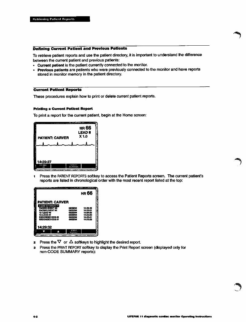
Retrieving Patient Reports
Defining Current Patient and Previous Patients
To retrieve patient reports and use the patient directory, itis important to understand the differencebetween the current patient and previous patients:• Current patient is the patient currently connected to the monitor.• Previous patients are patients who were previously connected to the monitorand have reports
stored in monitor memory in the patient directory.
Current Patient Reports
These procedures explain how to print or delete current patient reports.
Printing a Current Patient Report
To print a report for the current patient, begin at the Home screen:
1 Press the PATIENT REPORTS softkey to access the Patient Reports screen. The current patient'sreports are listed in chronological order with the most recent report listed at the top:
ffi
PATIENT: CARVER•JJAmilUH^Ull
PACING EVENT #2PACING EVENT #112-LEAD #212-LEAD «
RECORDED ECG §2RECORDED ECG «1
hr66
06/26/94 14:26:1008/25/94 1426:0106/25/94 14:24:3506/25/94 14:22:5006/25/94 14:20:4106/23/94 14:18:32
fl
2 Press the V or A softkeysto highlight the desired report.3 Press the PRINT REPORT softkey to display the Print Report screen (displayed only for
non-CODE SUMMARY reports):
6-2 LIFEPAK 11 diagnostic cardiac monitor Operating Instructions
/^\

PATIENT: CARVERcodesummarytopacing event «2 06/25/94
iUri/
hr66
12-LEAD 01RECORDED ECG #2RECORDED ECG #1
08/25/94 14:22:5008/25/94 14:20:4108/25/94 14:18:32
14:29:36
Retrieving Patient Reports
If desired, press softkeys:COPY SIZE changes copy size to X0.25, 0.5,1.0, 2.0, or 4.0 (default is same aswhen report was stored).MONITOR changes frequency response to DIAG (diagnostic) or MONITOR (default issame as when report was stored).SPEED changes print speed to 25 or 50mm/S.Press PRINT softkey to print report.Press EXIT to return to the Home screen.
Deleting a Current Patient Report
You can delete any report for the current patient except the CODE SUMMARY report.To delete a current patient report:i At the Home screen, press the PATIENT REPORTS softkey to access the Patient Reports screen:
p
PATIENT: CARVER•J.I.I^I|I,I!M:11H]
PACING EVENT #2PACING EVENT #112-LEAD #212-LEAD #1RECORDED ECG «RECORDED ECG #1
14:29:32
08/25/9408/25/9406/25/9406/25/9408/25/9406/25/94
W&fflHjP*.
hr66
14:26:1014:26:0114:24:3514:22:50
14:20:4114:18:32
2 Press the V or A softkeys to highlight the desired report:
w™*»»**«?»™^^ , .II'IN,,.'M. Mi
PATIENT: CARVERCODE SUMMARY^PACING EVENT #2PACING EVENT «
RECORDED ECG «2RECORDED ECG #1
14:29:32
06/25/9408/25/94
06/25/9406/25/94
hr66
14:26:10
14:26:01
14:20:41
14:18:32
3 Press the DELETE REPORT softkey to display the Delete Report screen:
LIFEPAK 11 diagnostic cardiac monitor Operating Instructions0April1996, Physio-Control Corporation
6-3

Retrieving Patient Reports
hr66
DELETE WILL ERASE REPORT:12-LEAD ECG #1 06/25/94 14:22:50
ON PATIENT:CARVER, GEORGE
14:29:57
4 You can delete the report or cancel the delete request:• To delete the report, press the DELETE softkey. The Patient Reports screen is then displayed
without the deleted report.After the report is deleted it cannot be recovered. However, the deleted report remains listed inthe Event Log in the CODE SUMMARY report.
• To cancel the delete request, press the CANCEL REQUEST softkey or press EXIT. The PatientReports screen is then displayed.
s To exit the Patient Reports screen and return to the Home screen, press EXIT.
Patient Directory and Previous Patient Reports
All the reports for previous patients and the current patient are accessible through the patientdirectory.
Gaining Access to the Directory
To gain access to the directory:1 Turn the monitor POWER switch to BATT and adjust CONTRAST as needed.2 Disconnect the patient cable from the monitor or the patient.3 From the Home screen, press the DIRECTORY softkey to display the Patient Directory screen:
1HR
DIRECTORY
ANDREWS 06/25/94 12:42:45062594103241 06/25/94 10:32:41
062594072341 06/25/94 07:23:41SMITH 06/25/94 04:35:13062494192531 06/24/94 19:25:31062494142435 06/24/94 14:24:35062494093425 06/24/94 09:3425COOKE 06/24/94 06:51:33TATE 06/23/94 18:39:46
14:32:37
•HBi^iSSBSiiisssKsssses SSSSS!-
Patients are listed in chronological order in the directory with the most recent patient listed at thetop. If more than 10 patients are listed, additional screens are accessible.
To exit the Patient Directory screen and return to the Home screen, press EXIT.
6-4 LIFEPAK 11 diagnostic cardiac monitor Operating Instructions

JfjpN
Retrieving Patient Reports
Printing a Report for Any Patient
To print a report for any patient:
i From the Patient Directory screen, pressV or A to highlight the desired patient(such as SMITH below):
DIRECTORYCARVERANDREWS062594103241
062494192531
062494142435062434093425COOKETATE
14:32:37
06/25/9406/25/9406/25/94
06/24/9406/24/9406/24/9406/24/9406/2304
HR
1420:2812:42:451032:41
1925:311424:350934250651:381839:46
2 Press the patient REPORTS softkey to display the Patient Reports screen:
HR
PATIENT: SMITH, MARKEHEBHMaa
12-LEAD #2 06/25/9412-LEAD #1 06/25/94RECORDED ECG #2 06/25/94DEFIBRILLATION *2 06/25/94DEFIBRILLATION #1 06/25/94RECORDED ECG #1 0025/94
14:32:52
04:44:5204:412804:382404:36:3004:35:450435:13
Press the V or A softkeys to highlight the desired report.Press the PRINT REPORT softkey to print the report. For non-CODE SUMMARY reports, pressadditional softkeys to change copy size, recorder frequency response, and speed (ifdesired).Then press the PRINT softkey. The recorder prints the report. (The default copy size and frequencyresponse is the same as when the report was stored.)After printing, press EXIT to return to the Patient Directory screen. To return to the Home screen,press EXIT again.
LIFEPAK 11 diagnostic cardiac monitor Operating Instructions"April 1996, Physio-Control Corporation
6-3
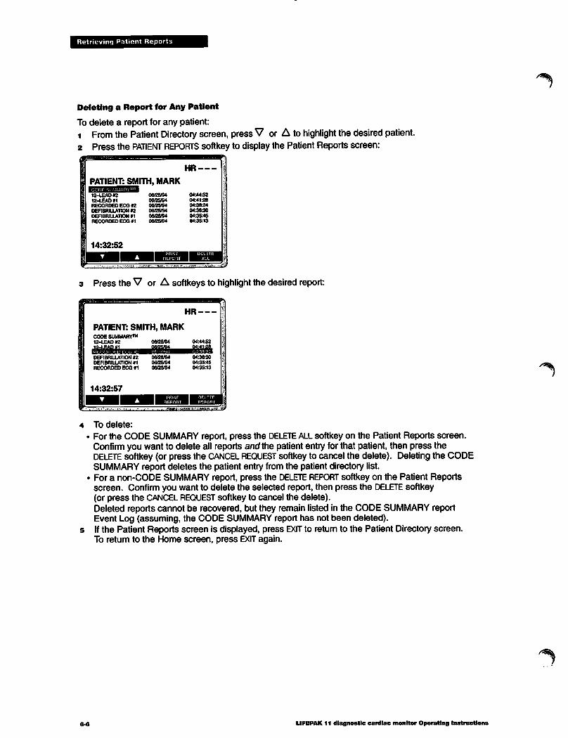
Retrieving Patient Reports
Deleting a Report for Any Patient
To delete a report for any patient:1 From the Patient Directory screen, pressV or A to highlight the desired patient.2 Press the PATIENT REPORTS softkey to display the Patient Reports screen:
HR
PATIENT: SMITH, MARKWSIBSRIBWaumBM
12-LEAD «212-LEAD fflRECORDED ECG »2DEFIBRILLATION 02DEFIBRILLATION «1RECORDED ECG 01
06/25/9406/25/9406/25/94
06/25/940605/9406/25/94
04:443204:41280438240436:300435:4504:35:13
3 Press the V or A softkeysto highlight the desired report:
HR
PATIENT: SMITH, MARKCODESUMMARY™12-LEAD #2
DEFIBRILLATION «2DEFIBRILLATION #1RECORDED ECG #1
14:32:57
06/25/9406/25/9406/25/94
04:44:52
04:36:3004:35:4504:35:13
To delete:
For the CODE SUMMARY report, press the DELETE ALL softkey on the Patient Reports screen.Confirm you want to delete all reports and the patient entry for that patient, then press theDELETE softkey (or press the CANCEL REQUEST softkeyto cancel the delete). Deletingthe CODESUMMARY report deletes the patient entry from the patient directory list.For a non-CODE SUMMARY report, press the DELETE REPORT softkey on the Patient Reportsscreen. Confirm you want to delete the selected report, then press the DELETE softkey(or press the CANCEL REQUEST softkey to cancel the delete).Deleted reports cannot be recovered, but they remain listed in the CODE SUMMARY reportEvent Log (assuming, the CODE SUMMARY report has not been deleted).Ifthe Patient Reports screen is displayed, press EXIT to return to the Patient Directory screen.To return to the Home screen, press EXIT again.
LIFEPAK 11 diagnostic cardiac monitor Operating Instructions
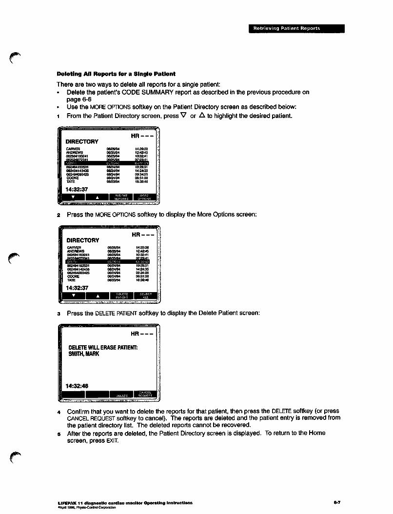
gp\
JlP^
Retrieving Patient Reports
Deleting All Reports for a Single Patient
There are two ways to delete all reports for a single patient:• Delete the patient's CODE SUMMARY report as described in the previous procedure on
page 6-6• Use the MORE OPTIONS softkey on the Patient Directory screen as described below:
1 Fromthe Patient Directory screen, press V or A to highlight the desired patient.
DIRECTORY
CARVERANDREWS
062594103241
062494192531062494142435
062494093425
COOKETATE
14:32:37
06/25/94
06/25/9406/25/94
06/24/94
06/24/9406/24/94
06/24/9406/23/94
HR
142028
12:42:4510:32:41
1925:311424:3509:34:2506:51:38
18:39:46
2 Press the MORE OPTIONS softkey to display the More Options screen:
^HR
DIRECTORY
CARVERANDREWS062594103241
062494192531062494142435
062494093425COOKETATE
14:32:37
06/25/9406/25/84
06/25/94
06/24/9406/24/9406/24/9406/24/94
06/23/94
14202812:42:45
10:32:41
1925:311424:3509:342506:51:38
18:39:46
3 Press the DELETE PATIENT softkey to display the Delete Patient screen:
HR
DELETE WILL ERASE PATIENT:SMITH, MARK
14:32:48
Confirm that you want to delete the reports for that patient, then press the DELETE softkey (or pressCANCEL REQUEST softkey to cancel). The reports are deleted and the patient entry is removed fromthe patient directory list. The deleted reports cannot be recovered.After the reports are deleted, the Patient Directoryscreen is displayed. To return to the Homescreen, press EXIT.
LIFEPAK 11 diagnostic cardiac monitor Operating Instructions°April 1996, Physio-Control Corporation
6-7

Retrieving Patient Reports
Printing the Directory Patient List
To print the directory patient list:1 From the Patient Directory screen, press the MORE OPTIONS softkey to display the More Options
screen as shown in the previous procedure.2 Press the SELECT ALL softkey to highlight all patients in the directory:
HR
3 Press the PRINT DIRECTORY softkey to print the directory patient list.4 After printing, press EXIT to return to the Patient Directory screen. To return to the Home screen,
press EXIT again.
Deleting the Entire Directory Contents
To delete the entire contents of the directory (except for reports for a current patient):1 From the Patient Directory screen, press the MORE OPTIONS softkey to display the
More Options screen.2 Press the SELECT ALL softkey to highlight all patients in the directory as shown in
the previous procedure.
3 Press the DELETE ALL softkey.4 Confirm that you want to delete the entire directory (except for current patient reports which are not
deleted), then press the DELETE softkey (or press CANCEL REQUEST softkey to cancel). The deletedreports cannot be recovered.
s After the reports are deleted, the Patient Directory screen is displayed. To return to the Homescreen, press EXIT.
6-8 LIFEPAK 11 diagnostic cardiac monitor Operating Instructions

Retrieving Patient Reports
Editing the Patient ID from the Directory
Any editing changes made to the patient ID from the directory are applied to all reports stored forthat patient. To edit the patient ID:
1 From the Patient Directory screen, press V or A to highlight the desired patient.2 Press the MORE OPTIONS softkey on the Patient directory screen, then press the PATIENT ID softkey
to display the Patient ID screen:
3 Press the ENT keyor the V orA softkeys to move through the patient ID fields. Use thealphanumeric keypad to enter data.
4 Press EXIT to return to the Patient Directory screen.
Transmitting Reports
You may transmit any or all patient reports from the patient directory. For detailed procedures, referto page 7-9.
LIFEPAK 11 diagnostic cardiac monitor Operating InstructionscApril 1996, Physio-Control Corporation
6-9

DATA COMMUNICATIONS
This section describes how to transmit a patient report from the LIFEPAK 11 diagnostic cardiacmonitor to another location via telecommunications. This section includes:
Overview of Data Communications page 7-2
Equipment Connections 7-4Transmitting a Report for the Current Patient 7-8
Transmitting Reports from the Directory 7-9
Configuration Options for Transmitting Reports 7-11Screen Messages during Successful Transmission 7-11
Troubleshooting Tips during Transmission 7-11
LIFEPAK 11 diagnostic cardiac monitor Operating Instructions 7-1•April 1996, Physio-Control Corporation

Data Communications
Overview of Data Communications
The LIFEPAK 11 monitor can transmit patient reports by telephone in two basic ways:• Landline communications
• Cellular communications.
The capability to transmit patient data via telecommunications may not be available in all countries.Contact your local Physio-Control representative for more information.
Landline Communications
When a landline is available, the monitor can be connected by modem to the Public SwitchedTelephone Network (PSTN). Upon command from the operator, the LIFEPAK 11 monitor transmitsthe patient report to the RS 100 receiving station through the PSTN.
The type of modem and connections vary in different countries. In the US and Canada, theLIFEPAK 11 monitor provides an internal modem that can be connected directly to the PSTN asshown in Figure 7-1.
Connection to
LANDLINE internalr-j I1—'J modem
LIFEPAK 11
monitor
LANDLINE
connection
Physio-Controlreceiving stationmodem
RS100receivingstation
Figure 7-1 Typical landline communications (US and Canada)
Outside the US and Canada, a non-Physio-Control external modem is used for landlinecommunications as shown in Figure 7-2. (The LANDLINE connector and internal modem are notavailable outside the US and Canada.)
Connection to SYSTEM
CONNECTOR serialrj channel
LANDLINE
connection
LIFEPAK 11
monitor
External modem
(non-Physio-Control)
Figure 7-2 Typical landline communications (Outside US and Canada)
7-2
Receiving stationmodem
(non-Physio-Control)
RS100
receivingstation
LIFEPAK 11 diagnostic cardiac monitor Operating Instructions
/^^

Data Communications
Cellular Communications
Cellular phone equipment is typically hand-carried or mounted in a vehicle as shown in Figure 7-3.The external cellular modem connects to the monitor SYSTEM CONNECTOR serial channel and the
PSTN-compatible cellular phone. The monitor transmits the patient report through the modem andcellular phone to the RS 100 receiving station via the cellular telephone network and the PSTN.
In the US and Canada, the Physio-Control CELLPAK™ kit provides a soft case that can be used forhand-carrying. The CELLPAK case accommodates the Physio-Control® cellular modem, aPSTN-compatible cellular phone (supplied by the customer), cables, and accessories. Outside theUS and Canada, contact the local Physio-Control representative for assistance in selecting acellular modem, cellular phone, and accessories.
As an alternative to hand-carrying, the cellular modem and a cellular phone can be installed in avehicle. A roof-mounted antenna can be used to improve cellular transmission.
Public
SwitchedTelephone
Network
Receivingstation
modem
II
I—h<
IVehicle-mounted
cellular phoneand modem
RS100
receivingstation
LIFEPAK 11
monitor
<L
Cellular
telephonenetwork
Hand-carried cellularphone and modem
Figure7-3 Typical cellular communications
& CAUTION Possible electrical interference and device malfunction.
When cellular phone poweris on, the cellular phoneemits low-power (typically <3W) radio frequencysignals. Avoid operating a cellular phone nearelectronic equipment notmanufactured byPhysio-Control Corporation. Before operating a cellular phone near other equipment, refer to theoperating instructions(for that equipment. Turn offcellular phone power when not inuse.
RS 100 receiving station
The RS 100 receiving station receives, prints, and stores patient reports from the LIFEPAK 11monitor. Ina typical application, the RS 100 receiving station is located at the hospital emergencyroom where medical personnel can review patient reports before the patient arrives.
As shown in Figure7-1, Figure 7-2, and Figure7-3, the RS 100 receiving station typically connectsto the PSTN through an external receiving station modem. Forthe USand Canada, the RS 100receiving station also contains an internal modem (not illustrated) that can be used to downloadreports to a storage device. Outside the US and Canada, the RS 100 receiving station downloadsreports through the external modem. For more information aboutthe operation and capabilities ofthe RS 100 receiving station and the Physio-Control receiving station modem, refer to the RS 100receiving station Operating Instructions.
LIFEPAK 11 diagnostic cardiac monitor Operating InstructionsoApril 1996. Physio-Control Corporation
7«3

Data Communications
Data Communications and Treatment Protocol
When considering any treatment protocol that involves the transmission of patient data bytelecommunications, some limitations must be recognized. Successful communication depends onaccess to public or private network services that may or may not always be available. This isespecially true for cellular communications which is influenced by many factors such as geography,location, weather, and the number of competing cellular service users. Therefore, treatmentprotocol must always take into account the fact that data transmission cannot be assured usinglandline or cellular communications. Your treatment protocol must include contingency planning forincomplete transmissions.
Equipment Connections
Before transmitting reports, make sure the monitor and accessories are properly connected asdescribed in this section. Although other types of equipment and connections are possible, theseare the typical and recommended connections using accessories and compatible equipment testedby Physio-Control. For information about connecting the RS 100 receiving station and accessories,refer to the RS 100 receiving station Operating Instructions. Contact your local Physio-Controlrepresentative for more information.
Before transmitting reports, confirm that the LIFEPAK 11 monitor and the RS 100 receiving stationare configured for the same language. If two different languages are configured, the RS 100receiving station prints reports in a mixture of the two languages. The language selection for theLIFEPAK 11 monitor is one of the Service Options described in the LIFEPAK 11 monitorServiceManual.
Modem Selection
The Physio-Control external cellular modem has been tested for use with the LIFEPAK 11 monitorin the US and Canada. Similarly, the Physio-Control receiving station modem has been tested foruse with the RS 100 receiving station in the US and Canada. Physio-Control does not recommendor provide support for use of non-Physio-Control modems in the US and Canada.
Outside the US and Canada, contact your local Physio-Control representative for assistance inselecting an external modem. Note that the LIFEPAK 11 monitorprovides a Modem Initializationoption which allows entry of character strings to initialize a non-Physio-Control modem (the ModemInitialization option does not pertain to a Physio-Control modem). Refer to page 10-7 for adescription of the option.
The LIFEPAK 11 monitor communications connectors and capabilities are described in Table 7-1.For additional technical information, refer to the LIFEPAK11 monitor Service Manual.
Table 7-1 LIFEPAK 11 monitor communications
Connector Description
SYSTEM Connection to serial channelCONNECTOR (compatible with EIA-RS232E)
LANDLINE RJ11 connection to internalmodem (compatible with Bell212A/CCITTV.22 1200bps)
Typical Application
Connection to external cellular modem
Direct landline connection to PSTN (connector andmodem not available outside US and Canada)
LIFEPAK 11 diagnostic cardiac monitor Operating Instructions
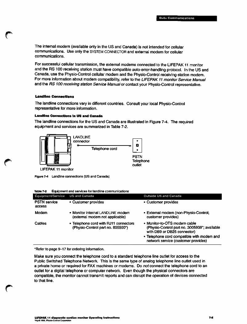
JP^N
JP^
Data Communications
The internal modem (available only in the US and Canada) is not intended for cellularcommunications. Use only the SYSTEM CONNECTOR and external modem for cellularcommunications.
For successful cellular transmission, the external modems connected to the LIFEPAK 11 monitorand the RS 100 receiving station must have compatible auto-error-handling protocol. In the US andCanada, use the Physio-Control cellular modem and the Physio-Control receiving station modem.For more information about modem compatibility, refer to the LIFEPAK 11 monitor Service Manualand the RS 100 receiving station Service Manual or contact your Physio-Control representative.
Landline Connections
The landline connections vary in different countries. Consult your local Physio-Controlrepresentative for more information.
Landline Connections in US and Canada
The landline connections for the US and Canada are illustrated in Figure 7-4. The requiredequipment and services are summarized in Table 7-2.
LANDLINE
Telephone cord
PSTN
Telephoneoutlet
LIFEPAK 11 monitor
Figure 7-4 Landline connections (US and Canada)
Table 7-2 Equipment and services for landline communications
Equipment/Service US and Canada
PSTN service
access
Modem
Cables
Customer provides
Monitor internal LANDLINE modem
(external modem not applicable)
Telephone cord with RJ11 connectors(Physio-Control part no. 805500*)
•Refer to page 9-17 for ordering information.
Outside US and Canada
Customer provides
External modem (non-Physio-Control;customer provides)
Monitor-to-OTS modem cable
(Physio-Control part no. 3005939*; availablewith DB9 or DB25 connector)Telephone cord compatible with modem andnetwork service (customer provides)
Make sure you connect the telephone cord to a standard telephone line outlet for access to thePublic Switched Telephone Network. This is the same type of analog telephone line outlet used ina private home or required for FAX machines or modems. Do not connect the telephone cord to anoutlet for a digital telephone or computer network. Even though the physical connectors arecompatible, the monitor cannot transmit reports and can disrupt the operation of devices connectedto that line.
LIFEPAK 11 diagnostic cardiac monitor Operating Instructions°April 1996, Physio-Control Corporation
7-5

Data Communications
Landline Connections Outside the US and Canada
The landline connections outside the US and Canada are illustrated in Figure 7-5. The requiredequipment and services are summarized in Table 7-2.
SYSTEM
n Telephone cord „•
External modem
(non-Physio-Control)
Telephoneoutlet
1
x Equipment and connectionsvary; consultPhysio-Control representativeLIFEPAK 11 monitor
Figure 7-5 Landline connections (outside US and Canada)
Cellular Connections
The cellular connections vary in different countries. Consult your local Physio-Controlrepresentative for more information.
Cellular Connections in US and Canada
The typical cellular connections for the US and Canada are illustrated in Figure 7-6. The requiredequipment and services are summarized in Table 7-3. The exact cellular phone connections andequipment may vary depending on the type of cellular phone you use.
SYSTEMCONNECTOR
LIFEPAK 11 monitor
Monitor-to-modem
cableCellular phone
Telephone Cellularcord connection Handset
device
May be carried in soft case of optional CELLPAK kit
Figure 7-6 Cellular connections (US and Canada)
7.6 LIFEPAK 11 diagnostic cardiac monitor Operating Instructions

Table 7-3 Equipment and services for cellular communications
Equipment/Service US and Canada
Cellular phonesupportingPSTN-signaling
Cellular phonenetwork access
Modem
Cables andaccessories
Customer provides*
Customer obtains
Physio-Control cellular modem(Physio-Control part number 805410*
Monitor-to-modem cable (Physio-Controlpart no. 805635**)
Telephone cord with RJ11 connectors(Physio-Control part no. 805500**)
Outside US and Canada
Data Communications
Customer provides
Customer obtains
External modem (non-Physio-Control;customer provides)
Monitor-to-OTS modem cable
(Physio-Control part no. 3005939**;available with DB9 or DB25 connector)Additional cables or equipment as needed(customer provides-consult phone supplier)
*CELLPAK case physically accommodates Motorola® MC480 Attache cellularphone (available in US and Canada)."Refer to page 9-17 for ordering information.
For easy transport, the optional Physio-Control CELLPAK case can accommodate the cellularmodem, cellular phone, phone battery, required accessories, and cables. Although the cellularmodem is compatible with any PSTN-compatible cellular phone, the CELLPAKcase is designed tophysically accommodate the Motorola MC480 Attache cellular phone. For information about thecontent and cable connections for the CELLPAK case, refer to the CELLPAK kit Reference Guide.
Cellular Connections Outside the US and Canada
The typical cellular connections for the US and Canada are illustrated in Figure 7-7. The requiredequipment and services are summarized in Table 7-3. The exact cellular connections varydepending on the type of cellular phone and modem you use.
SYSTEM
CONNECTOR
External modem
(non-Physio-Control)Cellular phone
I
p|| i=ftfpMonitor-OTS cable
LIFEPAK 11 monitor
Figure 7-7 Cellular connections (outside the US and Canada)
LIFEPAK 11 diagnostic cardiac monitor Operating Instructions"April 1996, Physio-Control Corporation
•D
Equipment and connections vary; consultPhysio-Control representative
7-7

Data Communications
Transmitting a Report for the Current Patient
To transmit a report for the current patient:
1 Checkphonecable connections (pages 7-5or 7-6). For cellular communications, apply powerto cellular phone; position the cellular phone a minimum of six inches away from the monitor andpatient connections to help reduce possible radio frequency interference with monitoring.
2 Press TRANSMIT button on monitor to display the Transmit screen:
pi i«PUSHTRANSMITTO SENDRECORDED ECO ill 15:17:24
Tosaaaa kksi
PATIENT: CARVER
15:18:42
HR66LEAD II
X1.0
^
NUM LOCK
••avmtiMK«.itiffi«JJWKiMM>«B:l»iKK»ii>
3 Confirm that the report you want to transmit is displayed in the upper left corner, or press theREPORT softkey as required to select the desired report to transmit. The most recently acquiredreport is displayed first.
When a CODE SUMMARY report is transmitted, it contains only the reports included for theconfigured CODE SUMMARY report format (long, medium, or short).
4 Confirm the desired transmit location and number are displayed in the upper left corner of thescreen, or do one of the following:
• Press the LOCATION softkey as required to select one of the stored transmit location numbers or• Enter the telephone number on the monitor alphanumeric keypad.
- You can add a prefix (such as an area code) to a stored location number. First, press theLOCATION softkey to display the stored number desired, then enter the desired prefix using thealphanumeric keypad (the stored number is blank while you add the prefix). Press LOCATIONagain to add the stored number to the displayed prefix.
- Either of two text characters may be specified as part of the number (if NUM LOCK is displayed,press the NUM key to enable alpha keys):
P causes pulse dialingW inserts a two-second wait period.
5 Confirm the desired transmission connector is selected: SYSTEM CONNECTOR softkey labelindicates cellular connection, LANDLINE softkey label indicates landline connection. Press thesoftkey to change selection if required.
6 After confirming the report, transmit location, and transmission connection, press TRANSMIT againto transmit the report.
7 Observe screen messages during transmission and take appropriate action if needed(troubleshooting tips are listed on page 7-12).
8 When transmission is complete (the TRANSMISSION COMPLETE message is displayed), press EXIT toreturn to the Home screen. For cellular communications, turn off power to the cellular phone.
To cancel a transmission in progress, press EXIT. Transmission also is cancelled if you pressRECORD, 12 LEAD, or CODE SUMMARY during transmission.
After any transmission attempt, the transmission result (Completed, Cancelled, or Failed) is listed in theCODE SUMMARY report Event Log along with the time of transmission and report type.
7-8 LIFEPAK 11 diagnostic cardiac monitor Operating Instructions

/(fPN
Data Communications
Transmitting Reports from the Directory
To transmit reports from the patient directory:1 Check phone cable connections (pages 7-5 or7-6). For cellular communications, apply power
to cellular phone; position the cellular phone a minimum ofsix inches away from the monitor andpatient connections to help reduce possible radio frequency interference with monitoring.
2 Disconnect the patient cable from the monitor or the patient.3 Press DIRECTORY softkeyto display the Patient Directory screen:
'HR
| DIRECTORYI ANDREWS 06/25/94 12:42:45
H 062594103241 06/25/94 10:32:41I 062594072341 06/25/94 07:23:41B SMITH 06/25/94 04:35:13n 062494192531 06/24/94 19:25:311 062494142435 06/24/94 14:24:35i 062494093425 06/24/94 09:3425i COOKE 06/24/94 06:51:38I TATE 06/23/94 18:39:46
1 14:32:37SHSid-
"i«iiss:r=sKSiisSfffiSssssmsss»s ;ss5S!5SS':S55SI»»ffisS
Nowthat you have accessed the patient directory, you may transmit a single report for any patient,transmit all reports for a patient, or transmit the entire directory contents.
Transmitting a Single Report for Any Patient
To transmit a single report from the directory:
i From the Patient Directory screen, press softkeys V or A to highlight the desired patient.2 Press the PATIENT REPORTS softkey to display the Patient Reports screen:
fHR
PATIENT: SMITH, MARK
12-LEAD#212-LEAD01RECORDED ECG 02DEFIBRILLATION «2
DEFIBRILLATION #1
RECORDED ECG#1
14:32:52
06/25/9406/25/94
06/25/9406/25/94
06/25/9406/25/94
04:44:52
04:412804:382404:38:3004:35:4504:35:13
Press softkeys V or A to highlight the desired reportto transmit.When a CODE SUMMARY report is transmitted, it contains only the reports included for theconfigured CODE SUMMARY report format (long, medium, short).
LIFEPAK 11 diagnostic cardiac monitor Operating Instructions°April 1996, Physio-Control Corporation
7-9

Data Communications
4 Press TRANSMIT to display the Transmit Report screen:
5 Perform steps 4 through 8 on page 7-8 to transmit the report.
Transmitting All Reports for a Patient
To transmit all reports for a single patient:i From the Patient Directory screen, press softkeys V or A to highlight the desired patient.2 Press TRANSMIT to display the Transmit Patient screen:
3 Perform steps 4 through 8 beginning on page 7-8 to transmit the reports.
Transmitting the Entire Directory Contents
To transmit the entire contents of the directory:i From the Patient Directory screen, press the MORE OPTIONS softkey to display the More Options
screen:
2 Press the SELECT ALL softkey to highlight all patients in the directory.
LIFEPAK 11 diagnostic cardiac monitor Operating Instructions

3 Press TRANSMIT to display the Transmit Directory screen:
^MtdMtoillM'tJMltMt<iwlilMM'lPlRMill
PUSH TRANSMIT TO SENDALLPATIENTS
DIRECTORY
ANDREWS05259410324!062534072341
SMITH062-!941925310-324O41.-.S435
0S2494093J25COOKE
14:32:48
HR
NUM LOCK
Data Communications
4 Perform steps 4 through 8 on page 7-8 to transmit the entire directory contents.
Configuration Options for Transmitting Reports
There are several transmission options which you may configure according to your needs:• Preset transmit location names and telephone numbers (maximum nine locations)• Default transmission connector (SYSTEM CONNECTOR or LANDLINE) displayed on Transmit screen• Optional audible tones during transmission (for landline only).
To configure these options, refer to Startup Defaults and Transmit Set-Up on pages 10-7 and 10-8.
Screen Messages During Successful Transmission
During a successful transmission the monitor typically displays the following sequence of messages:WAITING FOR DIAL TONE
MODEM INITIALIZATION
DIALING
TRANSMITTING
XX% TRANSMITTED
TRANSMISSION COMPLETE
Iftransmission is unsuccessful, refer to the troubleshooting information as follows.
Troubleshooting Tips During Transmission
Troubleshooting tips are provided in separate tables for cellular and landline communications. Forhelp in troubleshooting other monitor problems, refer to Troubleshooting on page 9-15. Beforetroubleshooting, be sure to have available replacement communication cables and fully-chargedbatteries.
LIFEPAK 11 diagnostic cardiac monitor Operating Instructions°April 1996. Physio-Control Corporation

Data Communications
Troubleshooting Tips for Cellular Transmission
If problems occur during cellular transmission, check the list of observations in Table 7-4 for aid introubleshooting.
Table7-4 Troubleshooting tips during cellular transmissionObservation
i Immediate, loud, rapid, busysignal.
2 BUSY* message and standardbusy signal.
3 Repeated ringing followed byCONNECTION FAILED*
message.
4 MODEM INITIALIZATION
message followed byCONNECTION FAILED*
message.
5 CHECK PHONE message.
6 CHECK CABLE message.
7 NO PHONE NUMBER message.
7-12
Possible Cause
Cellular service busy.
No cellular service atpresent location.
Destination receivingstation may be busyreceiving a report fromanother device.
Receiving station powernot on or cables notconnected at destination.
Wrong phone number.
Receiving phone line notactive.
Invalid modeminitialization string(non-Physio-Controlmodems only).
Phone power off.
Cable not connected or
damaged cable.
Phone battery low.
Antenna not extended or
securely connected.
Monitor-to-modem
(SYSTEM CONNECTOR)cable is not plugged inand no destination
phone number isentered.
No phone numberentered.
Corrective Action
• Press EXITto cancel transmission, thenretry in 30-60 seconds.
Move to another location and retry.
Press EXITto cancel transmission, thenretry in 30-60 seconds. If busy signalpersists, use phone handset to calldestination and determine whetherreceiving station modem answers.
Call and confirm destination receivingstation power is on and cables areproperly connected.Confirm phone number.Confirm destination receiving stationphone line is active.
Check string in modem initializationoption.
• Turn on phone power.
Check cable connections and retry.If problem persists, replace cable.
Install charged phone battery.Confirm antenna is properly extendedand connected.
Check monitor-to-modem cable and
enter a destination phone number.
Enter destination phone number bypressing LOCATION softkey or usingalphanumeric keypad.
LIFEPAK 11 diagnostic cardiac monitor Operating Instructions

Data Communications
Table7-4 Troubleshooting tips during cellular transmission, continuedObservation
8 TRANSMISSION FAILED*
message.
9 WAITING FOR DIAL TONE
message displayed for one ortwo minutes.
Possible Cause
Noisy phone line or poorcellular service.
Destination receivingstation memory full.
Monitor battery low.
Damaged ordisconnected antenna.
Phone battery low.
Antenna not extended.
Monitor battery low.
10Transmission starts but is very Monitor battery low.slow or fails to complete.
Phone battery low.
Poor cellular service inpresent location.
Corrective Action
• Retry. Ifproblem persists, move toanother location and retry.
• Retry transmission later or transmit toanother destination.
• Replace with fully-charged,properly-maintained battery.
• Check antenna and connections.
• Replace phone battery.• Extend antenna.
• Replace with fully-charged,properly-maintained battery.
Replace with fully-charged,properly-maintained battery.Replace phone battery.Move to another location and retry.
•Monitor automatically retries transmission once after CONNECTION FAILED, TRANSMISSION FAILED, or BUSYmessage.
LIFEPAK 11 diagnostic cardiac monitor Operating InstructionsoApri! 1996, Physio-Control Corporation
7-13

Data Communications
Troubleshooting Tips for Landline Transmission
If problems occur during landline transmission, check the list of observations in Table 7-5 for aid introubleshooting. The audible landline transmission tones may help identify problems. If the tonesare not audible, they may be enabled as described on page 10-7 (set TRANSMISSION AUDIO to ON orAUTO).
Table 7-5 Troubleshooting tips during landline transmissionObservation
i BUSY* message and standardbusy signal.
2 Repeated ringing followed byCONNECTION FAILED*
message.
3 MODEM INITIALIZATION
message followed byCONNECTION FAILED*
message.
4 CHECK PHONE message.
DIALING or REDIALING
message displayed for up totwo minutes.
6 NO PHONE NUMBER message.
7 TRANSMISSION FAILED*
message.
8 WAITING FOR DIAL TONE
message.
Possible Cause
Destination receivingstation may be busyreceiving a report fromanother device.
Receiving station powernot on or cables not
connected at destination.
Wrong phone number.
Receiving phone line notactive.
Invalid modem
initialization string(non-Physio-Controlmodems only).
RJ11 telephone cord notplugged in.
RJ11 telephone cordplugged into inactive ordigital phone jack.
Receiving station powernot on or cables not
connected at destination.
Wrong phone number.
Receiving phone line notactive.
No phone numberentered.
Noisy phone connection.
Destination receivingstation memory full.
Monitor battery low.
Monitor battery low.
9 Transmission starts but is very Monitor battery low.slow or fails to complete.
Corrective Action
Press EXITto cancel transmission, thenretry in 30-60 seconds. If busy persists,use phone handset to call destinationand determine whether receiving stationmodem answers.
Call and confirm destination receivingstation power is on and cables areproperly connected.Confirm phone number.Confirm destination receiving stationphone line is active.
Check string in modem initializationoption.
Confirm RJ11 cord plugged into monitorand phone jack.Plug RJ11 cord into a different analogphone jack and retransmit (analog phonejacks are the type used for a FAXmachine or computer modem).
Call and confirm destination receivingstation power is on and cables areproperly connected.Confirm phone number.Confirm destination receiving stationphone line is active.
Enter destination phone number bypressing LOCATION softkey or usingalphanumeric keypad.
Retry transmission.Retry transmission later or transmit toanother destination.
Replace with fully-charged,properly-maintained battery.
Replace with fully-charged,properly-maintained battery.
Replace with fully-charged,properly-maintained battery.
♦Monitor automatically retriestransmission once afterCONNECTION FAILED, TRANSMISSION FAILED, or BUSYmessage.
7«14 LIFEPAK 11 diagnostic cardiac monitor Operating Instructions

#^
DEFIBRILLATION/CARDIOVERSION/PACING
This section provides general information about using the LIFEPAK 11 diagnostic cardiac monitorwith LIFEPAK 11, LIFEPAK 5, or LIFEPAK 250defibrillators. This section does not includeoperation of the LIFEPAK 11 defibrillator/pacemaker with the LIFEPAK 11 monitor. For detailedinstructions regarding use of the LIFEPAK 11 defibrillator/pacemaker, including TroubleshootingTips, refer to the LIFEPAK 11 defibrillator/pacemaker Operating Instructions.
Topics in this section include:
Defibriljatiip JAftotoigsforine^r§tf[S^^K/loSifor ^S!§^^^^^^m^A^mati^!o7ifi#cSpipilate^ents fpr theLIFEPAK 11 mojltrtAuionfiatfeSHifofSelifivenlte IprlejfepEBftk 11 monftoffdSfibilllator/fa^Se^orln^L^Matic^[LjFlPAK5 or LIFEPAK 250 defibrillatorsScreen Messages*©/ trie UfIpAK 11monitor/defibn'llator/facemaker DuringDefibrilialior^nGhrpnized^CardioversionDefibriii&h^yncnrbriized Cardioversion Reportfor the LIFEPAK11 monitor/defibrillator/pacemaker
Screen Messages for the LIFEPAK 11monitor/defibrillator/pacemaker During PacingPacing Report forthe LIFEPAK 11monitor/defibrillator/pacemaker
Leads OMessage^LIFEPAK 5 defibrillator
LIFEPAK 250automatic advisory defibrillatorTroubleshooting TipsDuring defibrillation
LIFEPAK 11 diagnostic cardiac monitor Operating Instructions
page 8-2
"" Hi-3
B-5
8-6
8-6
8-8
8-9
8-9
8-10
8-12
8-1

Defibrillation/Cardioversion/Pacing
This section provides only a basic overview ofhow the LIFEPAK 11 defibrillator/pacemaker,LIFEPAK 5 defibrillator or LIFEPAK 250 defibrillator is used inconjunction with the LIFEPAK 11monitor. This section is not intended to replace the information provided inthe specific defibrillatorOperating Instructions.
Before using a defibrillator, the operator must be familiar with all ofthe safety information andoperating instructions provided in the LIFEPAK 11, LIFEPAK 5 or LIFEPAK 250 defibrillatorOperating Instructions. For clinical information, refer to these booklets: Defibrillation: What YouShould Kir?oiv and Noninvasive Pacing: What You Should Know.
Before using the LIFEPAK 11 monitor, be sure that the LIFEPAK 11 defibrillator/pacemaker,LIFEPAK 5 or LIFEPAK 250 defibrillator is operating properly and has been properly tested andmaintained.
Defibrillation Warnings
The term "defibrillator" in the warnings below refers to either the LIFEPAK 11, LIFEPAK 5 orLIFEPAK 250 defibrillator, when used with the LIFEPAK 11 monitor.
A WARNINGS
Possible shock.
When discharged, the defibrillator delivers up to 360 joules of electrical energy. Unless dischargedproperly as described in the defibrillator Operating Instructions, this electrical energy may causepersonal injury or death. Do not attempt to operate this device unless you are thoroughly familiar withthese Operating Instructions, the defibrillator Operating Instructions, and the function of all controls andindicators, as well as the connections and accessories.
Possible shock or burns and ineffective energy delivery.
The presence of precordial lead electrodes and lead wires may interfere with the recommendedplacement of hard paddles or defibrillation electrodes and prevent effective energy delivery. Do notallow physical contact between ECG electrodes and the paddles, defibrillation electrodes, ordefibrillation gel. Before performing defibrillation, remove from the patient any precordial lead electrodesand lead wires which may interfere with energy delivery.
Possible improper synchronization.
Monitoring the ECG through the standard paddles (QUIK-LOOK monitoring) may introduce artifact andlead to improper synchronization during cardioversion. Always use the patient ECG cable or theQUIK-COMBO or defibrillation electrodes to monitor ECG during synchronized cardioversion.
LIFEPAK 11 diagnostic cardiac monitor Operating Instructions
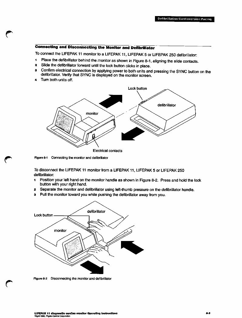
Defibrillation Cardioversion, Pacing
Connecting and Disconnecting the Monitor and Defibrillator
To connect the LIFEPAK 11 monitor to a LIFEPAK 11, LIFEPAK 5 or LIFEPAK 250defibrillator:1 Place the defibrillator behind the monitor as shown in Figure 8-1, aligning the slide contacts.2 Slide thedefibrillator forward until the lock button clicks in place.3 Confirm electrical connection by applying power to both units and pressing the SYNC button on the
defibrillator. Verify that SYNC is displayed on the monitor screen.4 Turn both units off.
Electrical contacts
Figure 8-1 Connecting the monitor and defibrillator
Lock button
To disconnect the LIFEPAK 11 monitor from a LIFEPAK 11, LIFEPAK 5 or LIFEPAK 250defibrillator:
1 Position your left hand on the monitor handle as shown in Figure 8-2. Press and hold the lockbutton with your right hand.
2 Separate the monitor and defibrillator using left-thumb pressure on the defibrillator handle.3 Pull the monitor toward you while pushing the defibrillator away from you.
Lock button
Figure 8-2 Disconnecting the monitor and defibrillator
LIFEPAK 11 diagnostic cardiac monitor Operating InstructionsoApril1996, Physio-ControlCorporation

Defibrillation/Cardioversion/Pacing
Monitor and Defibrillator Battery Power
When connected, themonitor and defibrillator can passelectrical signals through theelectricalcontacts. However, the defibrillator and monitor do not share power from either batteries or anauxiliary power source. For more information about monitor battery power, refer to page 2-7. Formore information about defibrillator battery power, refer to the defibrillator Operating Instructions.Note thatthe LOW BATTERY messageonthe monitor screen applies only to the monitor and not tothe defibrillator.
Automatic Storing of Defibrillation Events for the LIFEPAK 11monitor/defibrillator/pacemaker
When the LIFEPAK 11 monitor and LIFEPAK 11 defibrillator are connected, defibrillation events arestored automatically in the Code Summary report. Defibrillation events are described andillustrated on page 8-5.
Automatic Storing of Pacing Events for the LIFEPAK 11 monitor/defibrillator/pacemaker
When the LIFEPAK 11 monitor and the LIFEPAK 11 defibrillator/pacemaker are connected, pacingevents are automatically stored in the Code Summary report. Pacing events are described andillustrated in this section on page 8-6.
Recording Defibrillation Events for the LIFEPAK 5 or LIFEPAK 250 defibrillators
When the LIFEPAK 11 monitor and LIFEPAK 5 or LIFEPAK 250 defibrillator are connected, you canselect PADDLES lead to monitor and record the ECG through the paddles. The monitor stores aPADDLES recorded ECG in the CODE SUMMARY report.
Although the LIFEPAK 11 monitor allows paddles lead monitoring, the LIFEPAK 5 (or LIFEPAK 250)defibrillator does not inform the monitor when defibrillation energy is discharged. Therefore,defibrillation or synchronized cardioversion discharges are not automatically stored in memory orincluded in the Code Summary report.
Use either of these recommended ways to acquire a record of a defibrillation event:• Operate the recorder during defibrillation. The date, time, and patient ECG during the
defibrillation will be recorded on the paper printout. Save the printout.• Use an event key to mark the time of the defibrillation event in the CODE SUMMARY report. (ECG
data is not included with the event key.) Note that event keys cannot be used while anotheroperation, such as operating the recorder or acquiring a 12-Lead ECG report, is underway. Ifanother operation is underway, pressing an event key has no effect. For details, refer to page 5-6.
8-4 LIFEPAK 11 diagnostic cardiac monitor Operating Instructions

Defibrillation/Cardioversion/Pacing
22Xfn..M.essa£es Lor the LIFEpAK 11 monitor/defibrillator/pacemaker duringDefibnllation/Synchronized Cardioversion 9
When the LIFEPAK 11 monitor is connected to the LIFEPAK 11 defibrillator, the following screenmessages are displayed during defibrillation and synchronized cardioversion. For defibrillation andsynchronized cardioversion procedures, refer to the LIFEPAK 11 defibrillator/pacemaker OperatinqInstructions.
Defibrillation-The event is stored automatically atthe time of discharge.
STORING DEFIBRILLATION »1
PATIENT: CARVER
*,{J.wwKaaamwaW.aismfw>.,..Vf.ff|..,
Defibrillation event being stored.
Press to viewthe listof stored reports.
2 Synchronized cardioversion-The event is stored automatically at the time of discharge as adefibrillation event.
Monitorstores synchronized cardioversionas a defibrillation event.
SYNC displayed for synchronized cardioversion.
Press to view a list of stored reports.
3 To print a report, selecta defibrillation event from the list ofstored reports. See Section 6 for moreinformation on printing patient reports.
Use arrow keys to select desired report.
Press to print selected report.
LIFEPAK 11 diagnostic cardiac monitor Operating Instructions"April 1996, Physio-Control Corporation
8-5
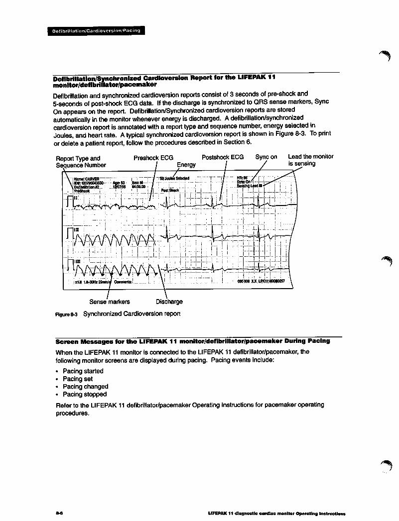
Defibrillation/Cardioversion/Pacing
Defibrillation/Synchronized Cardioversion Report for the LIFEPAK 11monitor/defibrillator/pacemaker
Defibrillation and synchronized cardioversion reports consist of 3 seconds of pre-shock and5-seconds of post-shock ECG data. If the discharge is synchronized toQRS sense markers, SyncOn appears on the report. Defibrillation/Synchronized cardioversion reports arestoredautomatically in themonitor whenever energy isdischarged. Adefibrillation/synchronizedcardioversion report is annotated with a report type and sequence number, energy selected inJoules, and heart rate. Atypical synchronized cardioversion report is shown in Figure 8-3. To printor deletea patient report, follow the procedures described in Section 6.
Report Type andSequence Number
Preshock ECG Postshock ECGEnergy
Sense markers Discharge
Figure 8-3 Synchronized Cardioversion report
Sync on Lead the monitoris sensing
Screen Messages for the LIFEPAK 11 monitor/defibrillator/pacemaker During Pacing
When the LIFEPAK 11 monitor is connected to the LIFEPAK 11 defibrillator/pacemaker, thefollowing monitor screens are displayed during pacing. Pacing events include:
• Pacing started• Pacing set• Pacing changed• Pacing stopped
Refer to the LIFEPAK 11 defibrillator/pacemaker Operating Instructions for pacemaker operatingprocedures.
8-6 LIFEPAK 11 diagnostic cardiac monitor Operating Instructions

Defibrillation/Cardioversion Pacing
1 When you press PACER on the LIFEPAK 11 defibrillator/pacemaker:• The default settings (ppm, mA, mode) appear• Sense markers appear on each detected intrinsic QRS complex• HR data and PATIENT REPORTS softkey disappear
HR data not available with PACER ON.
Default pacer settings
PATIENT REPORTS softkey does not appearwhen pacer is active.
2 When the pacing rate and current are set or later changed, these parameters are stored in themonitor as a Pacing Event.
STORING PACING EVENT #2
PATIENT: CARVER Pacing set event being stored.
PACER settingsjvYi-Vi^VfiA^^^^ '.^* During pacing, the PATIENT REPORTS softkey
on nnw M_* n™*"^ —FT dQQQ nQ{ appear80 PPM 65mA DEMAND
04:39:08
iaWg^WSBSSitaS^MWESB^gJ
3 When pacing is stopped (PACER OFF), the monitor screen restores HR data and the patientREPORTS softkey appears.
r STORING PACING EVENT #3 hr64LE>
PATIENT: CARVER X1.0
W)
Pacing stopped event being stored.
PATIENT REPORTS softkey appears whenpacing is stopped
4 Select pacing event for printing
To print a pacing report, select the desired report and press PRINT REPORT. See Section 6 for moreinformation on printing patient reports.
LIFEPAK 11 diagnostic cardiac monitor Operating Instructions"April 1996. Physio-Control Corporation

Defibrillation/Cardioversion/Pacing
HR
PATIENT: CARVERCODESUMMARY™12-LEAD0212-LEAD81
PACING EVENT #1RECORDED ECG #2DEFIBRILLATION «2DEFIBRILLATION «1RECORDED ECG *1
04:56:52
12/07/9512/07/9512/07/9512/07/9512/07/9512/07/95
04:412804:40:4004:39:08
04:39:0004:382404:36:30
04:35:4504:35:13
Use arrow keys to select desired report.
Press softkey to print selected report.
Pacing Report for the LIFEPAK 11 monitor/defibrillator/pacemaker
A pacing report consists of 3-seconds of pre-event and 5 seconds of post-event ECG data. Apacing report is stored automatically in the monitor when pacing is initiated with the LIFEPAK 11defibrillator/pacemaker. A pacing report is annotated withthe following information:
• Report type and sequence number• Type of pacing event (Pacing Started, Pacing Set, Pacing Changed, and Pacing Stopped)• Pacer settings including ppm (pacing rate inpulses per minute) and mA (milliamperes of pacing
current).
Pacing Started refers to when pacingcurrent is first delivered; PacingSet refers to the pacingparameters being established; Pacing Changed refers to when pacing parameters are changedfrom a previous setting; Pacing Stopped refers to when pacingcurrent ceases. Figure8-4 shows atypical pacing report. To printor delete a patient report, refer to the procedures described inSection 6.
Report Type andSequence Number
Event
Type
Figure 8-4 Pacing report
8-8
Pacer settings
Pacearrow
Pace marker
LIFEPAK 11 diagnostic cardiac monitor Operating Instructions

Defibrillation/Cardioversion/Pacing
Leads Off Messages During Pacing
When pacing for extended periods of time, static may build up on the ECG electrodes, causing theelectrodes to wear out. This possibility of static buildup, although unlikely, depends on the followingfactors:
• Pacing rate• Pacing current levels• Electrode placement• Patient impedance levels
If the electrode wears out, the message ECG LEADS OFF may appear, but pacing continues innon-demand mode. To resume pacing in DEMAND mode, apply new ECG electrodes to the patient.For more information, refer to the pacing troubleshooting tips described in the LIFEPAK 11defibrillator/pacemaker Operating Instructions.
LIFEPAK 5 defibrillator
The LIFEPAK 5 defibrillator may be connected to the LIFEPAK 11 monitor to allow ECG monitoringusing the PADDLES lead and synchronous cardioversion.
ECG Monitoring or Defibrillation
For information about ECG monitoring through paddles or defibrillation, refer to the LIFEPAK 5defibrillator Operating Instructions.
Synchronized Cardioversion with Standard Paddles
This procedure describes how to perform synchronized cardioversion using the LIFEPAK 5 defibrillatorstandard paddles while monitoring the patient through the LIFEPAK 11 monitor ECG electrodes. Analternate method of synchronized cardioversion is to install the FAST-PATCH adapter in the LIFEPAK5 defibrillator and to perform monitoring and defibrillation through the defibrillation electrodes. Refer tothe FAST-PATCH adapter Operating Instructions for more information.
To perform synchronized cardioversion with standard paddles:1 Connect the monitor and defibrillator.
2 Perform the steps required for limb lead ECG monitoring with the LIFEPAK 11 monitor (refer topage 3-3).
3 Slide the paddles out from the storage area.4 Press and release the black POWER button on the STERNUM paddle and confirm the green light is
on.
s Rotate the ENERGY JOULES switch on the APEX paddle to the desired level.6 Press the red SYNC button on the defibrillator and confirm the red light in the SYNC button is on.7 Confirm the monitor displays the Synchronized Cardioversion screen with the SYNC message as
shown below. Confirm the triangle sense markers appear on the QRS complexes. Ifthe sensemarkers do not appear or are displayed in the wrong locations, adjust ECG SIZE, select anotherlead, or reposition the ECG electrodes so the sense markers appear only on the QRS complexes.
LIFEPAK 11 diagnostic cardiac monitor Operating Instructions°April 1996, Physio-Control Corporation

Defibrillation/Cardioversion/Pacing
Ifhr160LEAD II
X1.0
SYNC
•Triangle sense markeron QRS complex
12:14:38
8 Perform the normal cardioversion procedure as described in the LIFEPAK 5 defibrillator OperatingInstructions.
After discharging, the defibrillator returns to the asynchronous mode: the red SYNC light is off andthe monitor does notdisplay the SYNC message or sense markers.
You may press RECORD on the monitor to activate the recorder and store a Recorded ECG report inmemory. The monitor does not store any specific information about the defibrillation event. If yourecord the ECG while the synchronous mode isenabled, the printed ECG report includes sensemarkers on thedisplayed ECG lead and the SYNC ON and SENSING LEAD notation at thetop asshown in Figure 8-5.
Sense markers, Sync On Lead the monitoris sensing
rum
J mv\r\fY\r\rY\r^www\x1.0 1.0-30HZ 25mm/s Comments: CPWOKEHIM 015 002 X.X LPK1178573
Figure 8-5 Sync notationon an ECG report
LIFEPAK 250 automatic advisory defibrillator
The LIFEPAK 250 automatic advisory defibrillator may be connected to the LIFEPAK 11 monitor toallow PADDLES lead ECG monitoring and defibrillation.
The ECG signal that the LIFEPAK 250 defibrillator supplies tothe LIFEPAK 11 monitor isfiltered byboth the defibrillator andthe monitor before itappears on the monitor screen or recording strip.This extra filtering dampens thedisplayed and printed ECG signal. Also, smaller amplitude internalpacemakerpulses maynotbe displayed or printed.
8*10LIFEPAK 11 diagnostic cardiac monitor Operating Instructions
/^Hi.
/^§\

Defibrillation/Cardioversion/Pacing
Therefore, the ECG signal from thedefibrillator that isdisplayed onthe monitor screen or recordingstrip should not be used for precise arrhythmia analysis. For accurate arrhythmia analysis, monitorthe patient directly through the monitor ECG cable, notthrough the LIFEPAK 250 defibrillator.
Defibrillation
Fordefibrillation instructions referto the LIFEPAK 250 defibrillator Operating Instructions.
ECG Monitoring
To monitor ECG with the LIFEPAK 250 defibrillator:
1 Connect the monitor and defibrillator.
2 Refer to the Operating Instructions for the defibrillation electrodes. Connect the defibrillationcables to the electrodes, then apply the defibrillation electrodes to the patient.
3 Rotate the LIFEPAK 11 monitor POWER switch to BAFT and select the PADDLES lead.
4 Lift up the LIFEPAK 250 defibrillator display module to apply power to the defibrillator.5 Observe the ECG signal on the monitor display. Adjust ECG SIZE and VOL as desired.
Troubleshooting Tips During Defibrillation
If problems occur with the LIFEPAK 11 monitor while using the LIFEPAK 5 or LIFEPAK 250defibrillator (such as monitoring through paddles or synchronized cardioversion), check the list ofobservations in Table 8-1 for aid in troubleshooting. (For help in troubleshooting problems with theoperation of the defibrillator, refer to the specific defibrillator Operating Instructions and ServiceManual.) For help in troubleshooting basic monitor operation, refer to Troubleshooting onpage 9-15. Troubleshooting tips for the LIFEPAK 11 defibrillator/pacemaker can be found in theLIFEPAK 11 defibrillator/pacemaker Operating Instructions.
Table 8-1 Troubleshooting tips while using a LIFEPAK 5 or LIFEPAK 250 defibrillator and monitor
Observation
i LIFEPAK 5 defibrillator:
monitor displays no signalwhen monitoring throughQUIK-LOOK paddles.
2 LIFEPAK 5 defibrillator:
Monitor displays much signalinterference while monitoringECG in PADDLES lead.
Possible Cause
PADDLES lead not
selected.
Devices not properlyconnected.
Foreign material onelectrical contacts where
devices connect.
Damaged paddles orpaddle cables.
Dirt or foreign materialon paddle electrodes.
Not enough defibrillationgel.
With FAST-PATCH
adapter: improper skinpreparation, pooradhesion to patient, orexpired electrodes.
LIFEPAK 11 diagnostic cardiac monitor Operating Instructions° April 1996, Physio-Control Corporation
Corrective Action
Select PADDLES lead.
Disconnect and reconnect monitor and
defibrillator.
Disconnect the defibrillator and monitor.
Inspect electrical contacts on bothdevices, remove foreign material, clean,and reconnect.
Check paddles and cables by performingtest on page 9-6.
Clean paddles.
Check application of gel.
Confirm proper skin preparation,electrode placement and contact,unexpired electrodes.
8-11

Defibrillation/Cardioversion Pacing
Table 8-1 Troubleshooting tips while using a LIFEPAK5 or LIFEPAK250 defibrillator and monitor, continued
Observation
3 LIFEPAK 5 defibrillator:
Cannot activate synchronous(SYNC) mode.
LIFEPAK 5 defibrillator:
Defibrillator SYNC activated and
monitor displays SYNC, butsense marker not displayed orin wrong place.
LIFEPAK 5 defibrillator with
FAST-PATCH adapter:monitor displays no signalwhen monitoring withdefibrillation electrodes.
LIFEPAK 250 defibrillator:
Monitor displays much signalinterference while monitoringECG in PADDLES lead.
8-12
Possible Cause
Devices not properlyconnected.
Foreign material onelectrical contacts where
devices connect.
QRS complexes notadequate size or shapeto be detected (sensed)by monitor.
PADDLES lead notselected.
FAST-PATCH adapter orpaddles not properlyinstalled.
Damaged FAST-PATCHadapter or cables.
Devices not properlyconnected.
Foreign material onelectrical contacts wheredevices connect.
With FAST-PATCHadapter: improper skinpreparation, pooradhesion to patient, orexpired electrodes.
Corrective Action
• Disconnect and reconnect monitor and
defibrillator.
• Disconnect the defibrillator and monitor.
Inspect electrical contacts on bothdevices, clean, reconnect.
• Press ECG SIZE to adjust so sensemarkers appear on QRS complex.
• Select another lead.
• Reposition ECG electrodes.
Select PADDLES lead.
Remove and reinstall FAST-PATCHadapter and paddles.
• Check FAST-PATCH adapter and cables:set ECG SIZE to X4.0 in PADDLES lead.Grasp defibrillator cable at junction ofelectrode leads and shake moderately,confirming monitor displays much signalnoise. Place metal face of two electrodesnaps together and shake moderately. Ifmonitor displays noisy signal, removeadapter and check defibrillator hardpaddles by performing test on page 9-6.If hard paddle function is ok, removeFAST-PATCH adapter from use andcontact service for repair or replacement.
Disconnect and reconnect monitor anddefibrillator.
Disconnect the defibrillator and monitor.Inspect electrical contacts on bothdevices, clean, and reconnect.
Confirm proper skin preparation, electrodeplacement and contact, unexpiredelectrodes.
LIFEPAK 11 diagnostic cardiac monitor Operating Instructions

Defibrillation Cardioversion Pacing
Table8-1 Troubleshooting tips while using a LIFEPAK 5 or LIFEPAK 250 defibrillator and monitor, continued
Observation
7 LIFEPAK 250 defibrillator:
Monitor displays no signalwhile monitoring withdefibrillation electrodes.
LIFEPAK 5 or 250
defibrillator: Patient did not
"jump" (no visible muscleresponse during defibrillatordischarge).
Possible Cause
PADDLES lead not
selected on monitor.
Devices not properlyconnected.
No defibrillator power.
Foreign material onelectrical contacts where
devices connect.
Patient muscle responseis variable and dependson patient condition.Lack of visible responseto defibrillation does not
necessarily mean thedischarge did not occur.
LIFEPAK 11 diagnostic cardiac monitor Operating Instructions0April1996. Physio-Control Corporation
Corrective Action
Confirm PADDLES lead selected.
Disconnect and reconnect monitor and
defibrillator.
Lift up defibrillator display module toconfirm power turns on and messagesappear on defibrillator display. If nopower, replace battery.
Disconnect the defibrillator and monitor.
Inspect electrical contacts on bothdevices, clean, and reconnect.
No action specified.

jps
^
MAINTAINING THE EQUIPMENT
This section describes how to perform operator-level maintenance, testing, and troubleshooting forthe LIFEPAK 11 monitor and selected accessories. For additional information about accessories,refer to specific accessory Operating Instructions. Topics in this section include:
General Maintenance and Testing page 9-2
Battery Maintenance and Testing 9-7
Troubleshooting 9-14
Service and Repair 9-16Warranty 9-16
Supplies, Accessories, and Training Tools 9-17
LIFEPAK 11 diagnostic cardiac monitor Operating Instructions 9-1°April 1996, Physio-Control Corporation
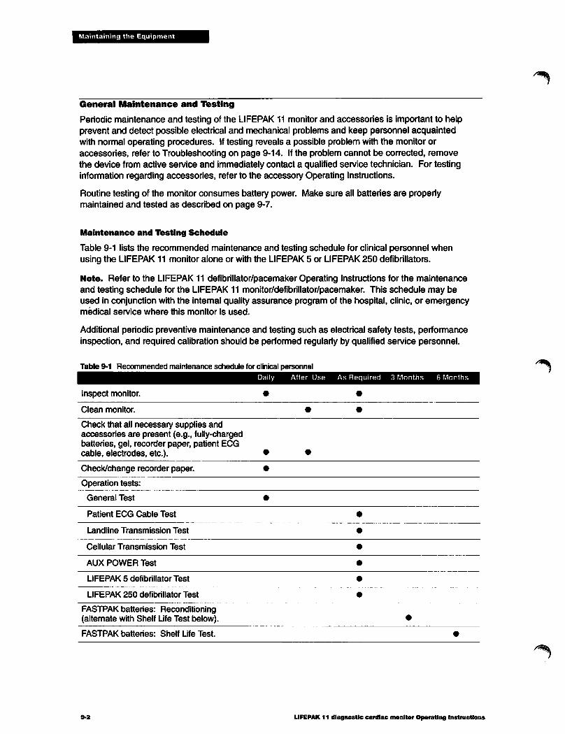
Maintaining the Equipment
General Maintenance and Testing
Periodic maintenance and testing of the LIFEPAK 11 monitor and accessories is important to helpprevent and detect possible electrical and mechanical problems and keep personnel acquaintedwith normal operating procedures. Iftesting reveals a possible problem with the monitor oraccessories, refer to Troubleshooting on page 9-14. Ifthe problem cannot be corrected, removethe device from active service and immediately contact a qualified service technician. For testinginformation regarding accessories, refer to the accessory Operating Instructions.
Routine testing of the monitor consumes battery power. Make sure all batteries are properlymaintained and tested as described on page 9-7.
Maintenance and Testing Schedule
Table 9-1 lists the recommended maintenance and testing schedule for clinical personnel whenusing the LIFEPAK 11 monitor alone or with the LIFEPAK5 or LIFEPAK 250 defibrillators.
Note. Refer to the LIFEPAK 11 defibrillator/pacemaker Operating Instructions for the maintenanceand testing schedule for the LIFEPAK 11 monitor/defibrillator/pacemaker. This schedule may beused in conjunction with the internal quality assurance program of the hospital, clinic, or emergencymedical service where this monitor is used.
Additional periodic preventive maintenance and testing such as electrical safety tests, performanceinspection, and required calibration should be performed regularly by qualified service personnel.
Table 9-1 Recommended maintenance schedule for clinical personnel
Inspect monitor.
Clean monitor.
Check that all necessary supplies andaccessories are present (e.g., fully-chargedbatteries, gel, recorder paper, patient ECGcable, electrodes, etc.).
Check/change recorder paper.
Operation tests:
General Test
Patient ECG Cable Test
Landline Transmission Test
Cellular Transmission Test
AUX POWER Test
LIFEPAK 5 defibrillator Test
LIFEPAK 250 defibrillator Test
FASTPAK batteries: Reconditioning(alternate with Shelf Life Test below).
FASTPAK batteries: Shelf Life Test.
9-2
Daily After Use As Required 3 Months 6 Months
LIFEPAK 11 diagnostic cardiac monitor Operating Instructions

Maintaining the Equipment
Inspection
Before any testing, perform a thorough visual inspection of the monitor case, accessories, andcables as described in Table 9-2.
Table 9-2 Inspection
LIFEPAK 11 monitor
case, accessories
LIFEPAK 11 monitor
battery pins
LIFEPAK 11 monitor
electrical slide contacts
LIFEPAK 11 monitor
Patient ECG Cable andother cables
Inspect for
Gel or foreign substances
Damage or cracks, improper mechanicalfunction of controls, covers, keypads,switches, recorder door
Loose pins
Bent, broken, corroded, worn, or damagedpins
Gel or foreign substances
Corrosion, deformities, bends, cracks, orbreaks (look closely for breaks at locationwhere contact enters the case)
Gel or foreign substances
While bending and flexing cable, inspectfor cracks, damage, cuts or abrasions,extreme wear, exposed inner wires, brokenor bent connectors and pins
Recommended Corrective Action
Clean as defined in Table 9-3
Contact service to replace orrepair
Tighten if loose
Contact service to replace
Clean as defined in Table 9-3
Contact service to replace orrepair
Clean as defined in Table 9-3
Replace
Cleaning
Clean the LIFEPAK 11 monitor, cables, and accessories as described in Table 9-3. Use only thecleaning agents listed in Table 9-3.
& CAUTION (Possible equipment damage;
Do not clean any part of the monitor, recorder, or cables with bleach, bleach dilution, or phenoliccompounds. Do not use abrasive cleaning agents. Do not steam, autoclave, or gas-sterilize theLIFEPAK 11 jmonitor or accessories unless otherwise stated In accessory Operating Instructions.:
Table 9-3 Recommended cleaning
Cleaning Practice Recommended Cleaning Agents
LIFEPAK 11 monitor
case, display, crevices,cracks, cables
LIFEPAK 11 monitor
recorder
Accessories
Clean with damp sponge or cloth.
Lift up door, remove paper roll, blowdust or debris out of compartment.Clean compartment with soft dry cloth.
Clean recorder printhead with soft drycloth.
Refer to accessory OperatingInstructions.
• Quaternary ammonium compounds• Isopropyl alcohol• Peracetic acid (peroxide) solutions
• No cleaning agent(only soft dry cloth)
• No cleaning agent(only soft dry cloth)
Refer to accessory OperatingInstructions.
LIFEPAK 11 diagnostic cardiac monitor Operating Instructions"April 1996, Physio-Control Corporation
9-3

Maintaining the Equipment
LIFEPAK 11 monitor General Test
Equipment Needed
• LIFEPAK 11 monitor
• Fully-charged battery
lest Procedure
1 Thoroughly inspect the LIFEPAK 11 monitor as described in Table 9-2.2 Remove the battery and inspect the battery pins for damage.3 Install a fully-charged battery in the monitor. Make sure recorder paper is installed in the recorder.4 Turn the monitor POWER switch to BATT, adjust the CONTRAST control, and confirm the monitor
powers on.
s After a few seconds confirm the monitor displays a flat-line signal with no SERVICE messagedisplayed.
e Press RECORD and confirm the recorder prints a recorded ECG report with the time and date.Press RECORD to turn off the recorder.
Patient ECG Cable Test
Equipment Needed
• LIFEPAK 11 monitor
• Patient ECG cable with limb lead and precordial lead attachments• 12-lead ECG simulator (with batteries)• Fully-charged battery
Test Procedure
i Thoroughly inspect the patient ECG cable as described in Table 9-2.2 Install a fully-charged battery in the monitor. Make sure recorder paper is installed in the recorder.3 Connect the patient ECG cable with limb lead and precordial lead attachments to the monitor.4 Connect all cable leads to the 12-lead ECG simulator.
s Turn the monitor POWER switch to BATT, adjust the CONTRAST control, and confirm the monitorpowers on.
6 Turn the simulator power on and select a rhythm.7 After a few seconds confirm the monitor displays a rhythm with no SERVICE or LEADS OFF messages
displayed.8 Press 12 LEAD and wait for the printout. Examine the printout and confirm a rhythm is printed for
each lead.
LIFEPAK 11 monitor Landline Transmission Test
To perform this test, you need access to a destination device that can receive a transmitted report.
Equipment Needed
LIFEPAK 11 monitor
Fully-charged batteryTelephone cord (with RJ11 connectors)Access to PSTN telephone lineAccess to destination device (RS 100 receiving station).
Test Procedure
i Confirm the destination device is on and ready to receive a report. Notify personnel at thedestination about the planned test.
2 Install a fully-charged battery in the monitor.3 Connect the telephone cord to the LIFEPAK 11 monitor LANDLINE connector and to the PSTN
telephone line outlet.4 Turn the monitor POWER switch to BATT and adjust the CONTRAST control.
LIFEPAK 11 diagnostic cardiac monitor Operating Instructions
/^\

Maintaining the Equipment
5 Press the TRANSMIT button on the monitor to display the Transmit Screen.6 Confirm that the displayed telephone number is correct for the intended destination. If incorrect,
enter the appropriate number on the alphanumeric keypad (or press the LOCATION softkey to selectthe appropriate preset number).
7 Confirm that the third softkey from the left is labeled LANDLINE (or press the SYSTEM CONNECTORsoftkey to change the label to LANDLINE).
8 Press the TRANSMIT button again to transmit the report.9 Confirm that the monitor completes the transmission and displays the message TRANSMISSION
COMPLETE.
io Contact a person at the destination device location and confirm the report was successfullyreceived.
LIFEPAK 11 monitor Cellular Transmission Test
To perform this test, you need access to a destination device which can receive a transmitted report.
Equipment Needed
LIFEPAK 11 monitor
Fully-charged batteryAccess to cellular network service
Access to destination device (RS 100 receiving station).Cellular telephone equipment: typically the Physio-Control cellular modem, monitor-to-modemcable, telephone cord, cellular phone, and any required supporting equipment such as a cellularconnection device, external antenna, and phone batteries.
Test Procedure
1 Confirm the destination device is on and ready to receive a report. Notify personnel at thedestination about the planned test.
2 Install a fully-charged battery in the monitor.3 Connect the cellular telephone equipment to the monitor (refer to page 7-7 for connection
information).
4 Apply power to the cellular phone.s Turn the monitor POWER switch to BATT and adjust the CONTRAST control.6 Press the TRANSMIT button on the monitor to display the Transmit Screen.7 Confirm that the displayed telephone number is correct for the intended destination. If incorrect,
enter the appropriate number on the monitor alphanumeric keypad (or press the LOCATION softkeyto select the appropriate preset number).
8 Confirm that the third softkey from the left is labeled SYSTEM CONNECTOR (or press the LANDLINEsoftkey to change the label to SYSTEM CONNECTOR).
9 Press the TRANSMIT button again to transmit the report.10 Confirm that the monitor completes the transmission and displays the message
TRANSMISSION COMPLETE.
ii Contact a person at the destination device location and confirm the report wassuccessfully received.
LIFEPAK 11 monitor AC AUX POWER Test
The AC Auxiliary Power Supply may not be available for use in all countries. Contact your localPhysio-Control representative.
Equipment Needed
• LIFEPAK 11 monitor
• AC Auxiliary Power Supply with access to power source.
LIFEPAK 11 diagnostic cardiac monitor Operating Instructions 9<S°April 1996, Physio-Control Corporation

Maintaining the Equipment
lest Procedure
1 Confirm the AC Auxiliary Power Supply is connected to AC power and the rear panel MAINSPOWER switch is set to 1 (ON).
2 Confirm the AC Auxiliary Power Supply front panel POWER light is illuminated.3 Make sure the battery is removed from the monitor.4 Connect the power module to the monitor.5 Turn the monitor POWER switch to AUX, adjust the CONTRAST control, and confirm the monitor
powers on with no SERVICE message displayed.
6 Install a battery in the monitor and confirm the left battery charging light illuminates on the powermodule.
LIFEPAK 11 monitor and LIFEPAK 5 defibrillator Test
This procedure tests the PADDLES ECG monitoring function and synchronized cardioversionfunction for the LIFEPAK 5 defibrillator when connected to the LIFEPAK 11 monitor. To test other
defibrillator functions, refer to the defibrillator Operation Instructions.
A WARNING Shock hazard.
When discharged as described in this test, the defibrillator delivers up to 20 joules of electrical energy.Unless discharged properly as described in this test, this electrical energy may cause serious personalinjury. Do not attempt to perform this test unless you are qualified by training and experience and arethoroughly familiar with these Operating Instructions, the defibrillator Operating Instructions, and thefunction of all controls, indicators, and any accessories used for the test.
Equipment Needed
LIFEPAK 11 monitor
Patient ECG cable with limb lead attachment
LIFEPAK 5 defibrillator
ECG simulator (with batteries)Fully-charged batteriesBattery Support System
lest Procedure
1 With the monitor and defibrillator not connected, thoroughly inspect the metal slide contacts wherethe devices can be joined. Remove any foreign substance.
2 Connect the monitor and defibrillator.
3 Install fully-charged batteries in the monitor and the defibrillator.4 Turn the monitor POWER switch to BATT, adjust the CONTRAST control, and confirm the monitor
powers on.
s Press the monitor LEAD SELECT to select PADDLES lead.
e Remove the paddles from the paddle storage area. Hold the paddles apart, gently shake them,and confirm the monitor displays a noisy, distorted signal.
7 Place the paddle electrodes firmly together and confirm the monitor displays a flat-line signal.8 Connect patient ECG cable with limb lead attachment to the monitor.
9 Connect cable leads to the ECG simulator.
10 Turn simulator power on and select a normal sinus rhythm.11 Press the monitor LEAD SELECT to select LEAD II.
12 Press the defibrillator POWER switch on the STERNUM paddle and confirm the green light illuminates.13 Rotate the APEX paddle ENERGY JOULES switch to select 20 joules.14 Press the red SYNC button on the defibrillator and confirm the red light in the SYNC button is on.
LIFEPAK 11 diagnostic cardiac monitor Operating Instructions

Maintaining the Equipment
is Confirm the monitor displays the triangle sense markers on QRS complexes. If sense markers donot appear or appear in the wrong locations, adjust ECG SIZE until they appear on the QRScomplexes.
16 Place the paddles firmly on the Battery Support System test load plates. Make sure the paddleelectrodes do not contact your hands or any surface except the test load plates.
17 Press the black CHARGE button on the APEX paddle to initiate the charge.is When defibrillator is fully charged (the CHARGE light glows steadily) simultaneously press and hold
red discharge buttons on both paddles.19 Confirm the defibrillator discharges when the next sense marker occurs. Confirm the red light in
the SYNC button turns off after the discharge.20 Place defibrillator paddles back into the paddle storage area.
LIFEPAK 11 monitor and LIFEPAK 250 defibrillator Test
This procedure tests the paddles ECG monitoring function for the LIFEPAK 250 defibrillator whenconnected to the LIFEPAK 11 monitor. To test other defibrillator functions, refer to the defibrillatorOperating Instructions.
Equipment Needed
• LIFEPAK 11 monitor
• LIFEPAK 250 defibrillator
• Physio-Control Patient Simulator (with batteries)• Fully-charged batteries
Test Procedure
1 With the monitor and defibrillator not connected, thoroughly inspect the metal slide contacts wherethe devices can be joined. Remove any foreign substance.
2 Connect the monitor and defibrillator.
3 Install fully-charged batteries in monitor and defibrillator.4 Turn the monitor POWER switch to BATT, adjust the CONTRAST control, and confirm the monitor
powers on.
5 Press the monitor LEAD SELECT to select PADDLES lead.
6 Connect the defibrillation cable to the Patient Simulator.
7 Press the Patient Simulator ON button to turn on power.8 Press Patient Simulator NSR button and confirm red indicator is illuminated.
9 Lift up the defibrillator display module to apply power to the defibrillator.io Confirm that the monitor displays the NSR ECG rhythm.
Battery Maintenance and Testing
The LIFEPAK 11 diagnostic cardiac monitor uses FASTPAK Nickel-Cadmium (NiCad) batteries.These NiCad batteries must be properly maintained using the Battery Support System to helpmaximize battery life and performance. For more information, refer to the Battery Support SystemOperating Instructions and LIFEPAK 11 diagnostic cardiac monitor Service Manual.
LIFEPAK 11 diagnostic cardiac monitor Operating Instructions 9-7°April 1996, Physio-Control Corporation

Maintaining the Equipment
& WARNINGS
Possible power failure.
Using a battery affected by voltage depression may result in power failure during patient care withoutwarning. Be sure to properly maintain batteries as described in this section.
Possible instrument failure.
Physio-Control has no information regarding the performance or effectiveness of the LIFEPAK 11monitor if used in conjunction with non-FASTPAK Physio-Control batteries or remanufactured oralternate source batteries or chargers from other sources. Use only the Physio-Control FASTPAKbatteries and the Battery Support System.
Possible battery damage.
The two-well Battery Charger (Physio-Control Part Numbers 9-00284, 9-00288, and 801530) is notdesigned to charge FASTPAK batteries. Charging the FASTPAK battery in the two-well standardBattery Charger may reduce battery life and create a risk of fire or explosion. Do not charge theFASTPAK battery in the standard Battery Charger.
Possible instrument failure.
The AC Auxiliary Power Supply does not maintain batteries. Use only the Battery Support System tomaintain batteries. The AC Auxiliary Power Supply does not replace the Battery Support System.
Possible instrument failure.
Failure to charge a stored battery before returning it to active service may result in premature powerfailure of the monitor or defibrillator during patient care. Always charge a stored battery before returningit to active service.
NiCad Battery Performance Factors
Three major factors affect the performance of NiCad batteries: temperature, voltage depression,and the self-discharge rate.
Temperature
Charging a battery at temperatures below 20°C (68°F) or above 25.5°C (78°F) will prevent thebattery from reaching its full capacity and may lead to irreversible cell damage.
Voltage Depression
Voltage depression is a condition which reduces battery performance, particularly when chargingthe defibrillator. This condition is often mistakenly called "memory." Voltage depression can usuallybe reversed by reconditioning the battery every 3 months as described in Figure 9-1 on page 9-10.Voltage depression is caused by either 1) repeatedly attempting to add more charge to afully-charged or a nearly fully-charged battery, or 2) extended charging at temperatures above themaximum recommended 25.5°C (78°F).
9.8 LIFEPAK 11 diagnostic cardiac monitor Operating Instructions

Maintaining the Equipment
Self-Discharge Rate
Like most batteries, NiCad batteries self-discharge when they are not used. A new NiCad batteryself-discharges approximately 1% of its capacity each day when stored at roomtemperature. In tendays a new NiCad battery not installed in the defibrillator/monitor loses approximately 10% of itscapacity. The self-discharge rate of the battery can be evaluated by performing a Shelf-Life Test.The actual battery self-discharge rate depends on:• Battery age• Temperature• Frequency of use• Length of time in storage• Physical battery condition.
These factors can combine to significantly increase the battery discharge rate. For example, an olderbattery stored in higher temperatures may have an accelerated self-discharge rate much greater than1%aday.
& CAUTION Possible battery damage.
Remove and replace a batterywhen the LOW BATTERY message first appears. Over-discharging can
Charging a Battery with the Battery Support System
To charge a battery in the Battery Support System:1 Insert the battery in one of the three battery compartments. Confirm the CHARGE light is on
indicating the charge cycle has begun.2 Periodically check on the battery until the READY light is on (full charge requires approximately
70 minutes). The battery is now fully charged and ready for use.
The FAULTY Light
If the Battery Support System displays the FAULTY light when a battery is installed, leave the batteryinstalled for up to 30 minutes. Then remove and reinsert the battery to reinitiate the charge cycle.Ifthe FAULTY light remains on, discard the battery.
Using the Battery Support System to Maintain Batteries
To properly maintain batteries, use only the Battery Support System with the following guidelines:• Charge batteries at the proper temperature.
The optimum charging temperature is room temperature, or 20° to 25.5°C (68° to 78°F). Batteriescharged outside room temperature may not reach full capacity even ifthe charge time is increased.This may lead to irreversible cell damage.
• Place the Battery Support System in proper location.- Place in a well-ventilated area
- Keep at room temperature- Do not place in direct sunlight- Do not place near a heat source or an air conditioner.
Rotate batteries so all batteries in active service are used equally.
LIFEPAK 11 diagnostic cardiac monitor Operating Instructions 9.9•April 1996. Physio-Control Corporation

Maintaining the Equipment
Recondition Batteries Every Three Months
Reconditioning is a succession of discharge/charge cycles which may be performed on a batteryinserted in the far rightcompartment of the Battery Support System. Reconditioning a battery helpsprevent or reverse the effects of voltage depression and helps keep track of battery capacity.
Perform reconditioning every threemonthsaccording to the Reconditioning Procedure inFigure 9-1. Discard any battery with a capacity reading of less than 80% on the thirdcycle. Forinformation about ordering copies of the Reconditioning Procedure form, refer to page 9-17.
RECONDITIONING PROCEDURE
Foruse with the Physio-Control® Battery Support System,FASTPAK® and Battery Pak batteries.- 80% or greater battery capacity is acceptable- Alternate every 90 days with Shelf LifeTest- Use Battery Support System at 68-78° F- For Technical Support, call (800)442-1142 USA
Test Date. Battery ID.
Performed by.
CHECKLIST (V circlewhen done)
O 1 Charge battery until READYlight appears
O 2 Cycle #1: DISCHG-CHARGE-READY; disregard reading
O 3 Cycle #2: DISCHG-CHARGE-READY; disregard reading
O 4 Remove battery for 1 - 4 hrs Begin End
O 5 Cycle #3: DISCHG-CHARGE-READY; bat. cap. = %
O 6 Log Cycle #3 bat. cap.% on back of battery
Cycle #3 bat. cap. 80% or greater?
O Yes-acceptable
O No-unacceptable/discard battery
P/N 806017-001 © 1993 Physio-Control Corporation
Figure 9-1 Reconditioning Procedure form
9-10 LIFEPAK 11 diagnostic cardiac monitor Operating Instructions

Maintaining the Equipment
Perform Shelf Life Test Every Six Months
The Shelf Life Test evaluates the self-discharge rate of a stored battery. Perform the Shelf Life Testdescribed in Figure 9-2 everysix months, oralternate it with theReconditioning Procedure inFigure 9-1 every three months. Discard any battery with a Shelf Life Test value of more than 20.For information about ordering copies of the Shelf Life Test form, refer to page 9-17.
Figure 9-2 Shelf Life Test
SHELF LIFE TEST
Foruse with the Physio-Control® Battery Support System,FASTPAK® and Battery Pak batteries.- Shelf LifeTest Value of 20 or less is acceptable- Alternate every 90 days with Reconditioning Procedure
(Note: Steps 1-5 equals Reconditioning Procedure)- Use Battery Support System at 68-78° F- For Technical Support, call (800)442-1142 USA
Test Date Battery ID.
Performed by.
CHECKLIST (V circle when done)
O 1 Charge battery untilREADY lightappears
O 2 Cycle #1: DISCHG-CHARGE-READY; disregard readingO 3 Cycle#2: DISCHG-CHARGE-READY; disregard readingO 4 Remove battery for 1 - 4 hrs Begin EndO 5 Cycle #3: DISCHG-CHARGE-READY; bat. cap. = %06
07
08
Log Cycle #3 bat. cap.% on back of battery
Remove battery for 7-8 days and store on shelf
Begin / / End / /
Cycle #4: DISCHG-CHARGE-READY; bat. cap. =_
Record: Cycle #3 bat. cap.
Subtract: Cycle #4 bat. cap. —_
Result: Shelf Life Test Value =_
Shelf Life Test Value 20 or less?
O Yes-acceptable O No-unacceptable/discard batteryP/N 806018-O01 © 1992 Physio-Control Corporation
LIFEPAK 11 diagnostic cardiac monitor Operating Instructions°April 1996, Physio-Control Corporation

Maintaining the Equipment
Use Battery Maintenance Log
The Battery Maintenance Log shown in Figure 9-3 is available to help track battery maintenanceprocedures. For information about ordering copies of the Battery Maintenance Log, refer topage 9-17.
BATTERY MAINTENANCE LOGFor use with the Battery Support System for Physio-Control
• Faulty• Reconditioning
Procedure
• Shelf Life TestD Visual Inspection
(case not cracked or broken)
• Faulty• Reconditioning
Procedure
• Shelf Life Test• Visual Inspection
(case not cracked or broken)
• Faulty• Reconditioning
Procedure
• Shelf Life Test• Visual Inspection
(case not cracked or broken)
• Faulty• Reconditioning
Procedure
• Shelf Life Test• Visual Inspection
(case not cracked or broken)
• Faulty• Reconditioning
Procedure
• Shelf Life Test• Visual Inspection
(case not cracked or broken)
• Faulty• Reconditioning
Procedure
• Shelf Life Test• Visual Inspection
(case not cracked or broken)
• Faulty• Reconditioning
Procedure
• Shelf Life Test• Visual Inspection
(case not cracked or broken)
Battery Capacity.
Shelf Life Test Value.
Case OK D Case not OK •
Battery Capacity.
Shelf Life Test Value.
Case OK • Case not OK •
Battery Capacity.
Shelf Life Test Value.
Case OK • Case not OK •
Battery Capacity.
Shelf Life Test Value.
Case OK • Case not OK •
Battery Capacity.
Shelf Life Test Value.
Case OK • Case not OK •
Battery Capacity.
Shelf Life Test Value.
Case OK • Case not OK •
Battery Capacity.
Shelf Life Test Value.
Case OK • Case not OK •
DYES
• YES
• YES
• YES
• YES
• YES
• YES
• NODiscardBattery
• NODiscard
Battery
• NODiscardBattery
• NODiscardBattery
• NODiscard
Battery
• NODiscard
Battery
• NODiscardBattery
P/N 806019-00 ' 1992 Physio-Control Corporation Technical Sen/ice 1(800) 442-1142 USA
Figure 9-3 Battery Maintenance Log
9-12 LIFEPAK 11 diagnostic cardiac monitor Operating Instructions
/*%

Maintaining the Equipment
Receiving New Batteries
When newly-purchased batteries are received:• Promptly labeleach new battery. Use a unique identification number so you can easily track the
battery through all maintenance and rotation.• Recondition each new battery. Because NiCad batteries self-discharge, a new battery maynot
be fully charged bythe time it is received. Recondition a newly purchased battery according tothe Reconditioning Procedure in Figure 9-1.
Storing Batteries
Store batteries in the Battery Support System or on a shelf. Batteriesstill require routinemaintenance, even while in storage. When storing on a shelf:• Store batteries between 4.4° and 26.7°C (40°and 80°F). Cooler temperatures reduce the
battery self-discharge rate.• Never freeze batteries.
Discarding Batteries
When properly maintained, the Physio-Control FASTPAK NiCad batteries should have a battery lifeof approximately two years. Discard a battery in an environmentally safe manner ifone ormoreofthe following circumstances occur:• Battery capacity is less than 80% after reconditioning• There is a difference of greater than 20 after performing a battery Shelf Life Test• There is physical damage to the battery case
^ • The Battery Support System indicates FAULTY when you try to recharge the battery
Recycling Batteries
When properly maintained, the Physio-Control NiCad batteries should have a battery life ofapproximately 2 years. A NiCad battery has reached the end of useful life if one or more of thefollowing circumstances occur:
• Battery capacity is less than 80% after reconditioning• There is a difference of greater than 20 after performing a battery Shelf Life Test• There is physical damage to the battery case• The Battery Support System indicates FAULTY when you try to recharge the battery
To promote awareness of battery recycling, Physio-Control NiCad batteries are marked with on ofthese symbols:
Ni-Cd H <®Whena Physio-Control NiCad battery has reached the end of its useful life, recyclethe batteryasdescribed below.
LIFEPAK 11 diagnostic cardiac monitor Operating Instructions°April 1996. Physio-Control Corporation

Maintaining the Equipment
Battery Recycling in the USA
Recycle NiCad batteries by participating with Physio-Control Corporation in a national batteryrecycling program. Contact your Physio-Control representative to obtain shipping instructions andbattery shipping containers. Do not return your batteries to the Physio-Control CorporateHeadquarters in Redmond, Washington, unless instructed to do so by your Physio-Controlrepresentative.
Battery Recycling Outside the USA
Recycle NiCad batteries according to national and local regulations. Control your localPhysio-Control representative for assistance.
Troubleshooting
If a problem with the monitor is detected during operation or testing, refer to the troubleshooting tipsin Table 9-4. Ifthe problem cannot be corrected, remove the monitor from active service andcontact a qualified service technician for service and repair.
g.14 LIFEPAK 11 diagnostic cardiac monitor Operating Instructions
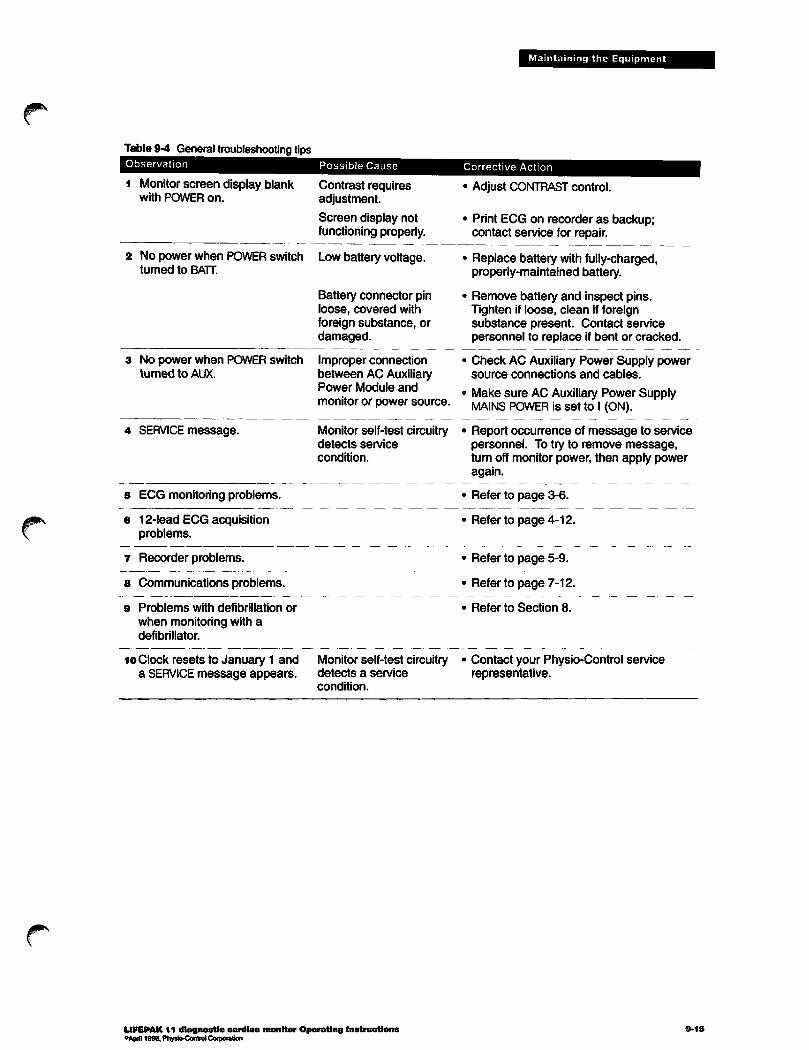
Table 9-4 General troubleshooting tipsObservation
1 Monitor screen display blankwith POWER on.
2 No power when POWER switchturned to BATT.
3 No power when POWER switchturned to AUX.
4 SERVICE message.
s ECG monitoring problems.
6 12-lead ECG acquisitionproblems.
7 Recorder problems.
8 Communications problems.
9 Problems with defibrillation or
when monitoring with adefibrillator.
10 Clock resets to January 1 anda SERVICEmessage appears.
Possible Cause
Contrast requiresadjustment.
Screen display notfunctioning properly.
Low battery voltage.
Battery connector pinloose, covered withforeign substance, ordamaged.
Improper connectionbetween AC AuxiliaryPower Module and
monitor or power source.
Monitor self-test circuitrydetects service
condition.
Monitor self-test circuitrydetects a service
condition.
LIFEPAK 11 diagnostic cardiac monitor Operating InstructionsoApril 1996. Physio-Control Corporation
Maintaining the Equipment
Corrective Action
• Adjust CONTRASTcontrol.
• Print ECG on recorder as backup;contact service for repair.
• Replace battery with fully-charged,properly-maintained battery.
• Remove battery and inspect pins.Tighten if loose, clean if foreignsubstance present. Contact servicepersonnel to replace if bent or cracked.
• Check AC Auxiliary Power Supply powersource connections and cables.
• Make sure AC Auxiliary Power SupplyMAINS POWER is set to I (ON).
• Report occurrence of message to servicepersonnel. To try to remove message,turn off monitor power, then apply poweragain.
• Refer to page 3-6.
• Refer to page 4-12.
• Refer to page 5-9.
• Refer to page 7-12.
• Refer to Section 8.
Contact your Physio-Control servicerepresentative.

Maintaining the Equipment
Service and Repair
& WARNING Possible shock.
Do not attempt to remove the instrument cover to service or repair this instrument. Contact qualifiedservice personnel for service or repair.
Ifthe LIFEPAK 11 monitor requires service as indicated by testing, troubleshooting, or the SERVICEmessage, contact the local Physio-Control service representative. In the USA, call Physio-ControlTechnical Services at 1-800-442-1142.
When calling Physio-Control to request service, identify model and serial number and describe theobservation. If the device must be shipped to a service center or the factory, pack the device in theoriginal shipping container, if possible, or in protective packing to prevent shipping damage.
The LIFEPAK 11 monitor Service Manual provides detailed technical information to support serviceand repair by qualified service personnel.
Warranty
Refer to the warranty statement which is included in the accessory kit shipped with the product. Forduplicate copies, contact the local Physio-Control representative. In the USA call 1-800-442-1142.
9-16 LIFEPAK 11 diagnostic cardiac monitor Operating Instructions

Maintaining the Equipment
Supplies, Accessories, and Training Tools
Supplies, accessories, and training tools for the LIFEPAK 11 monitor are listed inTable9-5.For information aboutordering, contact the local Physio-Control representative. In the USA, call1-800-442-1142.
Table 9-5 Supplies, Accessories, and Training ToolsDescription Part Number
AC Auxiliary Power Supply 806311DC Auxiliary Power Supply 806311Battery Support System 801807Battery Support System wall bracket assembly 80256212-Lead ECG Patient Simulator 805505Cellular modem 805410RS 100 receiving station 805285Receiving station modem 805634Patient ECG cable (includes main cable, limblead attachment, and precordial lead 805265attachment)
FASTPAK battery 09-10424Recorder paper, 100mm 805319LIFE-PATCH ECG electrodes, adult 800139
Event key label (applied under keypad cover) 806121Soft carrying case, LIFEPAK 11 monitor only 806099Soft carrying case, LIFEPAK 11 monitor and LIFEPAK 5 defibrillator 806098CELLPAK kit (does not include cellular modem or cellular phone) 805505Cables:
DC output cable for the AC Auxiliary Power Supply 804219Telephone cord (with RJ11 connectors) 805500Monitor-to-modem cable (connects LIFEPAK 11 monitorand Physio-Controlcellular modem) 805635Monitor-to-OTS modem cable (connects LIFEPAK 11 monitor to Off-The-Shelf non-Physio- 3005939Control external modem; available with DB9 or DB25 connector—consult Physio-Control)Monitor-to-monitor cable (connects two monitors—for transferring configurations only) 806544Literature:
LIFEPAK11 monitor Operating Instructions 805493LIFEPAK 11 monitor Service Manual 805494
LIFEPAK 11 monitor General Reference Card 806014
LIFEPAK 11 monitor Communications Reference Card 805258
Physio-Control cellular modem Operating Instructions 805313Physio-Control cellular modem Service Manual 806294CELLPAK Reference Guide 806332
Physician's Guide to ECG Analysis 805260Reconditioning Procedure check sheet 806017Shelf Life Test check sheet 806018
Battery Maintenance Log check sheet 806019
& CAUTION Possible excessive leakage current.
Ajceesisones # products other than those described in the UFEPAK11 monitor §imrMim^^ruGtiohsmay increase the overall leakage current if connected to the LIFEPAK 11 monitor.
LIFEPAK 11 diagnostic cardiac monitor Operating InstructionsoApril 1996,Physio-Control Corporation
9-17
jp\
SETUP/CONFIGURATION OPTIONS
The User Configuration Options allow you to define operating features for the LIFEPAK 11 monitorsuch as device identification numbers, power-on default settings, and 12-lead ECG operatingfunctions. This section describes how to access and define the User Configuration Options:
Overview of Options and Factory Settings page 10-2
How to Access User Configuration Options 10-4
Device Identification 10-5
Device Features 10-6
Startup Defaults ~ 10-7Transmit Set-Up 10-8Modem Initialization 10-9
Default Printer Lead Group 10-10Event Key Definitions 10-10Transferring Configurations toAnother Monitor 10-11
LIFEPAK 11 diagnostic cardiac monitor Operating Instructions 10-1"April 1996. Physio-Control Corporation

Setup/Configuration Options
Overview of Options and Factory Settings
All User Configuration Options are listed in Table 10-1 along with the factory settings. The far rightcolumn (User Settings) is blank to allow you to photocopy Table 10-1 and write down thecustomized settings for your monitor.
Write Down Configurations Before Service or Repair
If the monitor receives service or repair which affects the internal memory components such asreplacement of the main printed circuit board, any changes previously made to the option definitionsmay be lost from memory. Before allowing service or repair, be sure to write down the current UserConfiguration Options in Table 10-1 so the customized definitions may be reentered after service orrepair.
Password Security
To prevent unauthorized access, a security password is required for access to the UserConfiguration Options. The password definition is partofthe Device Identification option and maybe changed.
Memory Storage of Configuration Options
User Configuration Option definitions are stored in memory and retained, even after the monitorPOWER switch is turnedoff or the battery is removed. Whenever you redefine options, the optionchanges are immediately stored in memory.
After redefining an option, do notturn off the power until the software updates the memory and themonitor displays the new option definition. Turning the power off prematurely may cause the UserConfiguration Options and Service Options to return to their default settings.
10*2 LIFEPAK 11 diagnostic cardiac monitor Operating Instructions

^s
0^*
Setup/Configuration Options
Table 10-1 User Configuration Options
Category
DEVICE
IDENTIFICATION
DEVICE
FEATURES
STARTUP
DEFAULTS
TRANSMIT
SET-UP
MODEM
INITIALIZATION
DEFAULT
PRINTER LEAD
GROUP
EVENT KEY
DEFINITIONS
Option
SITE #:
DEVICE #:
PASSWORD:
PATIENT ID SCREEN AVAILABLE?:
NUMBER OF 12-LEAD COPIES?:
CODE SUMMARY™ FORMAT?:12-LEAD CHANNEL FORMAT?:
PRINT INTERPRETATION ON 12-LEAD?:
PRINT JUSTIFICATION ON 12-LEAD?:
PRINT ACUTE Ml MESSAGE?:
12-LEAD DATA STORAGE MODE?:
12-LEAD DATA ACQUISITION MODE?:
COMMUNICATIONS MODULE?:
DISPLAY LEAD:
PRIMARY FILE IDENTIFIER:
TRANSMISSION PORT:
TRANSMISSION AUDIO:
RECORD FREQUENCY RESPONSE:
Factory Settings
000
000
Blank (no passwordrequired)
YES
1
LONG
3
YES
NO
YES
2.5
POST
NO
LEAD II
NAME
SYSTEM
AUTOMONITOR
LABEL DEFAULT RATE* PHONE NUMBER*
*Factorysetting is 38400 default rate, DIRECT connection.
AT*
AT*
AT*
AT
*Factory settings: String 1String 2String 3String 4
CHANNEL!
CHANNEL 2
CHANNEL 3
KEY EVENT
EVENT MARK
ATE0V0X4ATS12=38S7=60S10=50:E0@M18*H1)M1AT\N2\J0W0%C0\A3&D2&S1 -K1 %G1 %B2400(blank)
LEAD ILEAD IILEAD III
KEY EVENT
LIFEPAK 11 diagnostic cardiac monitor Operating InstructionsoApril 1996. Physio-Control Corporation
10-3

Setup/Configuration Options
How to Access User Configuration Options
To access the User Configuration Options:
1 Begin with monitor POWER switch OFF.2 Turn POWER to BATT while pressing and holding downthe EXIT and CODE SUMMARY buttons,
holding down these buttons for several seconds until the Password Screen is displayed:
PLEASE ENTER PASSWORDS(PRESS ENT WHEN COMPLETE)
15:29:37
Keep
Use the alphanumeric keypad to enter the password, then press the ENT key to display the UserConfiguration Options screen:
USER CONFIGURATION OPTIONS
DEVICE FEATURESSTARTUP DEFAULTSTRANSMIT SET-UPMODEM INITIALIZATIONDEFAULT PRINTER LEAD GROUPEVENT KEY DEFINmONS
If you do notenter the passwordcorrectly, the monitor exitsthe Password screen and displays theHome screen. Toaccess the Password screen again, perform steps 1 and 2 as described above. Ifthe password is configured as blank (like the factory setting) no password is required (press ENT).
4 Press theV or A softkeys to highlight the desired option.s Press the START softkey to access the options screen. Tomake changes in the
displayed options screen:
• Press softkeys V or A to move through the fields.• Press the SET softkey (if available) to change a setting.• After the desired changes are entered:• Press the NEXT SCREEN softkey to advance to the next options screen or press EXIT to return to
the User Configuration Options screen.6 After the desired changes are entered, press EXIT to exit the User Configuration Options screen
and return to the Home screen.
The TRANSFER CONFIG softkey on the UserConfiguration Options screen is used when transferringconfigurations to another monitor. Refer to page 10-11 for the procedure.
10-4 LIFEPAK 11 diagnostic cardiac monitor Operating Instructions
/^|

jp*
Setup/Configuration Options
Device Identification
The Device Identification options allow entry of a unique site number, device number, and password(for softkey descriptions, refer to Step 5 on page 10-4):
Table 10-2 Device Identification options
Option Settings
SITE #: Any number from 0-999.
DEVICE #: Any number from 0-999.
PASSWORD: Maximum of 8 characters
(alpha or numeric). Mayalso be blank.
Description
Number identifier which
prints on reports.*
Number identifier which
prints on reports.*
Restricts access to User
Configuration Options.
*lfthe site number or device number are changed, previously stored reports areunaffected. Reports are reprinted with the site number and device number configured atthe time the report was stored.
LIFEPAK 11 diagnostic cardiac monitor Operating Instructions"April 1996. Physio-Control Corporation
10-5
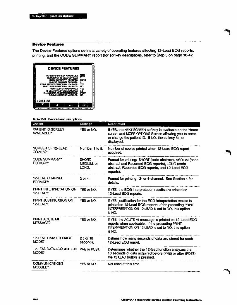
Setup/Configuration Options
Device Features
The Device Features options define a variety of operating features affecting 12-Lead ECG reports,printing, and the CODE SUMMARY report (for softkey descriptions, refer to Step 5 on page 10-4):
DEVICE FEATURES
PATIENT ID SCREEN AVAILABLE?: H5aNUMBER OF 12-LEAD COPIES?: 1
CODE SUMMARY- FORMAT?: LONG12-LEAD CHANNEL FORMAT?: 3
PRINT INTERPRETATION ON 12-LEAD?: YESPRINT JUSTIFICATION ON 12-LEAD?: NO
PRINT ACUTE Ml MESSAGE?: YES12-LEAD DATA STORAGE MODE?: 2.5
12-LEAD DATA ACQUISITION MODE?: POSTCOMMUNICATIONS MODULE?: NO
Table 10-3 Device Features options
Option
PATIENT ID SCREEN
AVAILABLE?:
NUMBER OF 12-LEAD
COPIES?:
CODE SUMMARY'FORMAT?:
12-LEAD CHANNEL
FORMAT?:
Settings
YES or NO.
Number 1 to 9.
SHORT,MEDIUM, orLONG.
3 or 4.
PRINT INTERPRETATION ON YES or NO.12-LEAD?:
PRINT JUSTIFICATION ON YES or NO.12-LEAD?:
PRINT ACUTE MlMESSAGE?:
YES or NO.
12-LEAD DATA STORAGE 2.5 or 10MODE?: seconds.
12-LEAD DATAACQUISITION PRE or POST.MODE?:
COMMUNICATIONSMODULE?:
10*6
YES or NO.
Description
IfYES, the NEXT SCREEN softkey is available on the Homescreen and MORE OPTIONS Screen allowing you to enteror change the patient ID. If NO, the softkey is notdisplayed.
Number of copies printed when 12-Lead ECG reportacquired.
Format for printing: SHORT (code abstract), MEDIUM (codeabstract and Recorded ECG reports), LONG (codeabstract, Recorded ECG reports, and 12-Lead ECGreports).
Format for printing: 3- or 4-channel. See Section 4 fordetails.
IfYES, the ECG interpretation results are printed on12-Lead ECG reports.
IfYES, justification for the ECG interpretation results isprinted on 12-Lead ECG reports. Ifthe preceding PRINTINTERPRETATION ON 12-LEAD is set to NO, this optionis NO.
IfYES, the ACUTE Ml message is printed on 12-Lead ECGreports when applicable. If the preceding PRINTINTERPRETATION ON 12-LEAD is set to NO, this optionis NO.
Defines how many seconds of data are stored for each12-Lead ECG report.
Determines whether the 12-lead function analyzes the10 seconds of data acquired before (PRE) or after (POST)the 12 LEAD button is pressed.
Not used at this time.
LIFEPAK 11 diagnostic cardiac monitor Operating Instructions
/"^|y

Setup/Configuration Options
Startup Defaults
The Startup Defaults options define the power-on settings for five features (for softkey descriptions,refer to Step 5 on page 10-4):
STARTUP DEFAULTS
DISPLAY LEAD:PRtMARY FILE IDENTIFIER:
TRANSMISSION PORTTRANSMISSION AUDIO:
RECORD FREQUENCY RESPONSE:
NAMESYSTEMAUTOMONITOR
Table 10-4 Startup Defaults options
Option
DISPLAY LEAD:
PRIMARY FILE
IDENTIFIER:
TRANSMISSION PORT:
TRANSMISSION AUDIO:
RECORD FREQUENCY
RESPONSE:
Settings
LEAD I, II, III,or PADDLES.
NAME or ID.
SYSTEM or
LANDLINE.
ON, AUTO, orOFF.
MONITOR or
DIAG
(diagnostic)
Description
Lead displayed at power-on.
Determines whether patient information is presented byname or ID whenever there is not enough room to displayboth references.
Default transmission connector at power-on.
Determines whether the landline transmission tones areaudible. If AUTO, the transmission tones are audible until thecarrier is detected, then the tones are disabled.
Defines the default printer frequency response for continuousrecorder operation and non-12-Lead ECG reports (12-LeadECG reports are always initially printed in diagnostic mode).Every report is stored in memory in diagnostic frequencyresponse. However, each report is printed in the samefrequency response that was selected at the time storedunless the operator manually overrides this selection at thetime of printing by pressing the MONITOR or DIAG softkey.This manual override only applies to the current report; afterthe report is printed, subsequent reports are reprinted in thesame frequency response selected when they were stored.
LIFEPAK 11 diagnostic cardiac monitor Operating InstructionseApril1996. Physio-Control Corporation
10-7

Setup/Configuration Options
Transmit Set-Up
The Transmit Set-Up option allows entry of phone numbers, labels, and baud rates for transmitlocations available through the Transmit screen when transmitting reports. Up to 9 transmitlocations may be defined (for softkey descriptions, refer to Step 5 on page 10-4):
TRANSMIT SET-UPDEFAULT RATE PHONE NUMBER
STLUKESHARBORVIEWSWEDISHEVERGREENOVERLAKEEVERETTSTJOKNSSTPAULS
12:19:48
300960096001200120038400960096009600
18008674000
887456912066544321PW5554447778907DIRECT484832152187775207840
Table 10-5 Transmit Set-Up option
Settings Description
LABEL Maximum 10 characters Name of destination displayed on Transmit screen,(alpha or numeric).
DEFAULT RATE
PHONE NUMBER
300, 1200, 2400, 4800,9600, 19200, or 38400.
Maximum 14 digits.*Allowable characters are
0-9, P, W.
Transmission baud rate.
Transmission phone number displayed on Transmit screen.Ifno number is entered, a direct connection is assumed (themonitor supplies the word DIRECT if this field is blank).
• P causes pulse dialing.• W inserts a two-second wait period.
*When defining the preset telephone numbers, configure only the local number. The user may add an area code oraccess code prefix if needed at the time of transmission.
10-8 LIFEPAK 11 diagnostic cardiac monitor Operating Instructions
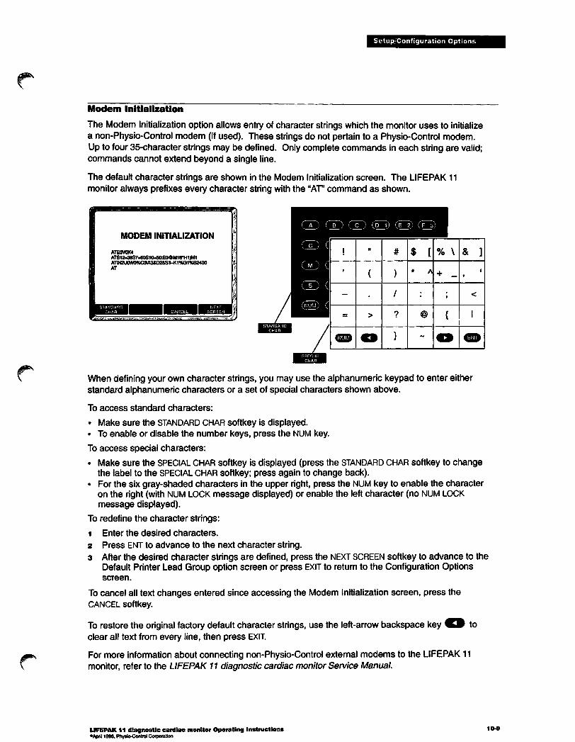
Setup/Configuration Options
Modem Initialization
The Modem Initialization option allows entry of character strings which the monitor uses to initializea non-Physio-Control modem (ifused). These strings do not pertain to a Physio-Control modem.Up to four 35-character strings may be defined. Onlycomplete commands in each string are valid;commands cannot extend beyond a single line.
The default character strings are shown in the Modem Initialization screen. The LIFEPAK 11monitor always prefixes every character string with the "AT* command as shown.
MODEM INITIALIZATION
ATE0V0X4ATS12=38S7*60S10=50£0OMia*H1)M1AT\N2\JCW0%C<M3&D2&S1-K1%G1%B2400AT
gB5y*
! ii
# $ [ % \ & ]
i
( ) * A + _i
i
-
•
/ J<
= > ? @ { 1
(^^ o } ~ O ^^
When defining your own character strings, you may use the alphanumeric keypad to enter eitherstandard alphanumeric characters or a set of special characters shown above.
To access standard characters:
• Make sure the STANDARD CHARsoftkey is displayed.• To enable or disable the number keys, press the NUM key.
To access special characters:
• Make sure the SPECIAL CHAR softkey is displayed (press the STANDARD CHAR softkey to changethe label to the SPECIAL CHAR softkey; press again to change back).
• For the six gray-shaded characters in the upper right, press the NUM key to enable the characteron the right (with NUM LOCK message displayed) or enable the left character (no NUM LOCKmessage displayed).
To redefine the character strings:
i Enter the desired characters.
2 Press ENT to advance to the next character string.3 After the desired character strings are defined, press the NEXT SCREEN softkey to advance to the
Default Printer Lead Group option screen or press EXIT to return to the Configuration Optionsscreen.
To cancel all text changes entered since accessing the Modem Initialization screen, press theCANCEL softkey.
To restore the original factory default character strings, use the left-arrow backspace key O toclear all text from every line, then press EXIT.
For more information about connecting non-Physio-Control external modems to the LIFEPAK 11monitor, refer to the LIFEPAK 11 diagnostic cardiac monitorService Manual.
LIFEPAK 11 diagnostic cardiac monitor Operating Instructions°April 1996, Physio-Control Corporation
10-9
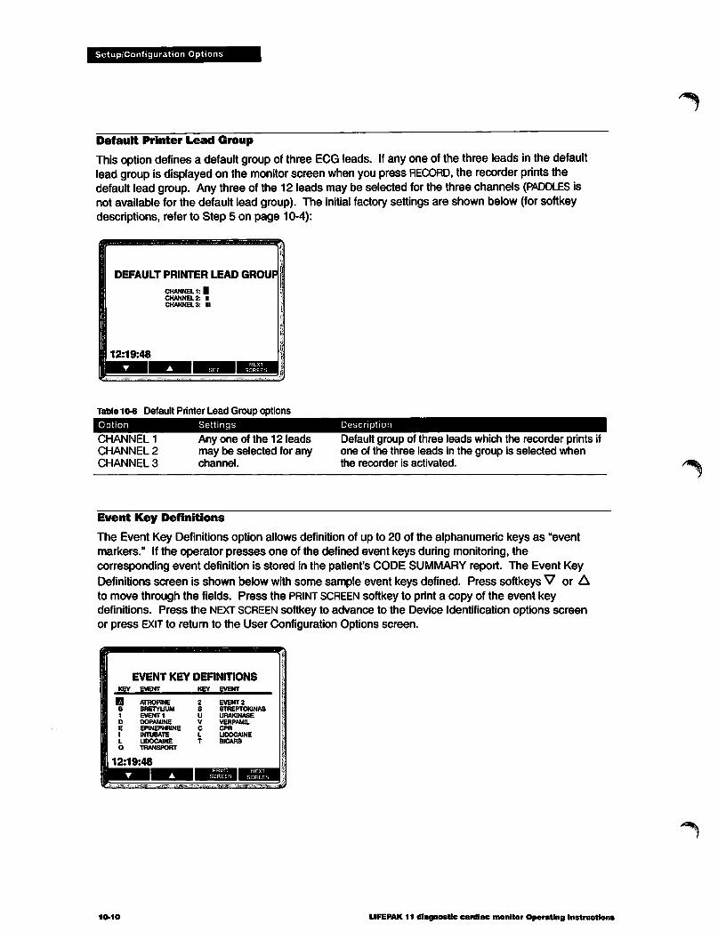
Setup/Configuration Options
Default Printer Lead Group
This option defines a defaultgroupof three ECG leads. If any one of the three leads in the defaultlead group is displayed on the monitor screen when you press RECORD, the recorderprints thedefault lead group. Any three of the 12 leads may be selected for the three channels (PADDLES isnot available for the default lead group). The initial factory settings are shown below (forsoftkeydescriptions, refer to Step 5 on page 10-4):
Table 10-6 Default Printer Lead Group options
Option
CHANNEL 1
CHANNEL 2
CHANNEL 3
Settings
Any one of the 12 leadsmay be selected for anychannel.
Description
Default group of three leads which the recorder prints ifone of the three leads in the group is selected whenthe recorder is activated.
Event Key Definitions
The Event Key Definitions option allows definition of up to 20 of the alphanumeric keys as "eventmarkers." If the operator presses one of the defined event keys during monitoring, thecorresponding event definition is stored in the patient's CODE SUMMARY report. The Event KeyDefinitions screen is shown below with some sample event keysdefined. Press softkeysV or Ato move through the fields. Press the PRINT SCREEN softkey to print a copy of the event keydefinitions. Press the NEXT SCREENsoftkey to advance to the Device Identification options screenor press EXIT to return to the User Configuration Options screen.
EVENT KEY DEFINITIONSKEY EVENT
10-10
ATROPINEBRETYUUMEVENT 1DOPAMINEEPINEPHRINEINTUBATEUDOCAINETRANSPORT
19:48
KEY EVENT
EVENT2STREPTOKINASURAKiNASEVERPAMIL
LIDOCAINEBICARB
LIFEPAK 11 diagnostic cardiac monitor Operating Instructions
^3sk

Setup/Configuration Options
Table 10-7 Event Key Definitions optionsField Settings Description
KEY Any single alphanumericcharacter.
Event key.
EVENT Maximum of 12
alphanumeric characters.Defines event. When operator presses event key during monitoring,this event definition is stored in CODE SUMMARY report.
Transferring Configurations to Another Monitor
The TRANSFER CONFIG softkey on the User Configuration Options screen (page 10-4) allows you totransfer User Configuration Options from one monitor to a second nearby monitor. Aftertransferring configurations, the second monitor is reconfigured with the same User ConfigurationOptions as the originating monitor except for the device number (DEVICE #) which remainsunchanged. Both monitors must be displaying the User Configuration Options screen in order totransfer the information. If the second monitor has a later software version that defines additional
User Configuration Options not existing in the originating monitor software, these fields are notaffected by the transfer.
The monitors must be connected through the SYSTEM CONN connectors using the Monitor-to-monitorcable. The information cannot be transferred through the LANDLINE connector or to a remotemonitor via telecommunications.
To transfer configurations, perform the following steps:Make sure that both monitors are displaying the User Configuration Options screen.Connect the Monitor-to-monitor cable (Part Number 806544) to the SYSTEM CONN connector oneach monitor.
Press the TRANSFER CONFIG softkey on the originating monitor to initiate the transfer.Observe the originating monitor screen for the displayed message. Refer to the messagedescription in Table 10-8 and take appropriate action (if required).
Table 10-8 Possible screen messages during configuration transfer
Screen Message
TRANSFERRING
CONFIGURATION
Description
Displayed on both monitors while they transfer the information.
TRANSFER COMPLETE Displayed on both monitors if information transfer successfully completes.
TRANSFER FAILED
CHECK CABLE
Displayed on both monitors (accompanied by three beeps) if they begintransferring information but cannot complete the operation successfully.• To restart the operation, begin with Step 1 above.• To abandon operation, press EXIT to exit to the Home screen.
Displayed by the originating monitor (accompanied by three beeps) if the cableis not connected properly or the receiving monitor is not displaying the UserConfigurations Options screen.• Reconnect the cable. If the monitors do not resume transfer, repeat the
procedure beginning with Step 1 above.• If the Options screen is not displayed, repeat the procedure beginning with
Step 1 above.
LIFEPAK 11 diagnostic cardiac monitor Operating Instructions"April 1996. Physio-Control Corporation
10-11

APPENDIX As SCREEN MESSAGES
r^ Table A-1 lists and describes screen messages that the LIFEPAK 11 monitor may display duringoperation. The messages are listed in alphabetical order with a page reference for moreinformation.
LIFEPAK 11 diagnostic cardiac monitor Operating Instructions A-1°Aprfl 1996, Physio-Control Corporation

Screen Messages
If the monitor displays a message not listed inTableA-1, contact Physio-Control Corporation formore information.
Table A-1 Summary of screen messages
Message
ACQUIRING 12-LEAD#x
ANALYZING 12-LEAD #x
BUSY
CANNOT TRANSMIT
REPORT
CHECK CABLE
CHECK PADDLES ANDELECTRODES
CHECK PAPER
CHECK PHONE
CONNECT LEADSCONNECT ECG LEADS
CONNECTION FAILED
*** DATA ERROR
DATA ERROR
DETECTED
DIALING
ECG LEADS OFF
ENERGY NOT
DELIVERED
EXCESSIVE NOISE:
12 LEAD REPORT
CANCELLED
xx LEADS OFF
LA LEADS OFF
LL LEADS OFF
Operation
Acquiring a12-LeadECG
Analyzing a12-Lead ECG
Data
communications
Data
Communications
Transferringconfigurations
Defibrillation
Creating patientreports
Data
communications
Description
Monitor is acquiring the data for 12-LeadECG report #x.
Monitor is analyzing the data for 12-LeadECG report #x.
Destination appears busy. Destinationphone is busy or not answering.
Attempt was made to transmit a report withdata error (cannot be transmitted).
Displayed by originating monitor ifcable isnot connected properly or receiving monitoris not displaying User ConfigurationsOptions Screen.
Displayed in conjunction with the ENERGYNOT DELIVERED message.
The recorder is out of paper or jammed.
Monitor waiting for response from modem.Cable disconnected or phone service notactive.
4-5
4-5
7-12,7-14
7-12,7-14
10-11
8-13
5-4
7-12,7-14
3-5ECG monitoring An ECG electrode is disconnected.
Data
communications
Data
Communications
Data
Communications
Data
communications
ECG monitoring
Defibrillation
Acquiring a12-LeadECG
ECG monitoring
ECG monitoring
ECG monitoring
Monitor does not transmit successfully and 7-12, 7-14stops trying. Destination phone is busy ornot answering.
Report contains a data error (cannot be 7-12, 7-14transmitted).
Attempt was made to transmit a report with 7-12, 7-14data error (cannot be transmitted).
Monitor is waiting for dial tone or dialing the 7-11,7-12,phone number. If DIALING displays for a long 7-14time with no response, the destinationphone may be busy or not answering.
Multiple ECG electrodes are disconnected. 3-5
No energy was delivered due to open circuit 8-13or other condition that prevented thetransfer of energy.
This message is displayed if the monitor 4-5detects noise too great to record a 12-LeadECG report, even if you attempt to overridethe WAITING FOR GOOD DATA message.
ECG electrode "xx" (such as "RA") is 3-5disconnected.
ECG electrode LA is disconnected. 3-5
ECG electrode LL is disconnected. 3-5
LIFEPAK 11 diagnostic cardiac monitor Operating Instructions

Table A-1 Summary of screen messages, continuedMessage Operation
LOW BATTERY FASTPAK
battery use
MODEM INITIALIZATION Datacommunications
NO REPORT TOTRANSMIT
NO PHONE NUMBER
NUM LOCK
PACING FAULT
PACING LEADS OFF
PACING STOPPED
Data
communications
Data
communications
Keypad use
Pacing
Pacing
Pacing
Screen Messages
Description
Monitor battery voltage is low. 2-7
Monitor is initializing non-Physio-Control 7-11,10-9external modem.
Attempt was made to transmit a 7-12, 7-14non-12-Lead ECG report to a device whichcannot receive non-12-Lead ECG reports.
No phone number is specified when 7-12,7-14transmission attempted.
The number keys are enabled on the 2-5, 2-6alphanumeric keypad.
Pacer has detected a pacing fault condition 8-13and pacing function stops.
Pacer has detected that the pacing 8-13electrodes are not connected or are not
making good contact with the patient.Pacing function stops.
Pacing has stopped due to a fault condition 8-13or when the pacer is turned off.
PRINTING 12-LEAD #x Acquiring a12-Lead ECG
Monitor is printing 12-Lead ECG report #x. 4-5
PRINTING
DEFIBRILLATION #XPrinting patientreports
Monitor is printing defibrillation report #xfrom the list of stored reports.
8-13
PRINTING
PACING EVENT #X
Printing patientreports
Monitor is printing pacing event report #xfrom the list of stored reports.
8-13
RA LEADS OFF ECG monitoring ECG electrode RA is disconnected. 3-5
RECORDER DOOROPEN
Creating patientreports
The recorder door is open. 5-4
RECORDING Creating patientreports
Printer is printing the ECG waveforms forthe displayed lead and lead group.
5-4
REDIALING Data
communications
Monitor is redialing the phone number. IfREDIALING displays for a long time with noresponse, the destination phone may bebusy or not answering.
7-12,7-14
RL LEADS OFF ECG monitoring ECG electrode RL is disconnected. 3-5
SERVICE Service and
repairThe monitor requires service by technicalservice personnel.
2-6, 9-14,9-14
STORING 12-LEAD #x Acquiring a12-LeadECG
Monitor is storing the data for 12-Lead ECGreport #x.
4-5
STORING
DEFIBRILLATION #XDefibrillation Monitor is storing data for defibrillation
event.
8-13
STORING
PACING EVENT #X
Pacing Monitor is storing data for pacing event. 8-13
STORING RECORDED
ECG#xCreating patientreports
Monitor is storing data for Recorded ECGreport #x.
5-4
LIFEPAK 11 diagnostic cardiac monitor Operating Instructions°April 1996, Physio-Control Corporation
A-3

Screen Messages
Table A-1 Summary ofscreen messages, continued
SYNC
TOO MANY DIGITS
Operation
Synchronizedcardioversion
Datacommunications
TRANSFER COMPLETE Transferringconfigurations
TRANSFER FAILED
TRANSFERRINGCONFIGURATION
TRANSMISSIONCANCELLED
TRANSMISSIONCOMPLETE
TRANSMISSION FAILED
xx% TRANSMITTED
TRANSMITTING
Vx LEADS OFF
WAITING FOR DIALTONE
WAITING FOR GOODDATA
A-4
Transferringconfigurations
Transferringconfigurations
Datacommunications
Datacommunications
Data
communications
Datacommunications
Datacommunications
ECG monitoring
Datacommunications
Acquiring a12-LeadECG
Description
Monitor is connected to a LIFEPAK 8-4defibrillator (with synchronous cardioversioncapability) and synchronous cardioversionis enabled.
Userattempted to specify a phone numberwith more than 14 digits.
Displayed on bothmonitors if theysuccessfullycomplete the informationtransfer.
Displayed on both monitors if they begintransferring information butcannotcompletethe operationsuccessfully.
Displayed on bothmonitors while theytransfer the information.
Operator cancelled transmission in progress 7-12,7-14by pressing EXIT oranother function button.
Monitor successfully transmits. 7-11
Monitor could notcomplete transmission. 7-12,7-14
7-12,7-14
10-11
19-11
10-11
xx% ofthe message has been transmitted. 7-11
Monitor is transmitting data.
ECG electrode "Vx" (such as "V1") isdisconnected.
Monitor waiting for response from modem.Disconnected cable or phone service notactive.
Monitor detects excessive signalinterference such as patient motion whileacquiring data. Message remains displayedwhile the monitor attempts to acquire datawithout interference.
7-11,7-12,7-14
3-5
7-12,7-14
4-5
LIFEPAK 11 diagnostic cardiac monitor Operating Instructions
/^^
APPENDIX B: SPECIFICATIONS
Table B-1 lists the specifications for the LIFEPAK 11 diagnostic cardiac monitor.
LIFEPAK11 diagnostic cardiac monitor Operating InstructionsoAoril 1996. Phvsio-Control Corporation

Specifications
Table B-1 LIFEPAK 11 diagnostic cardiac monitor specifications
POWER
AC Input Options
Battery
Operating Time
Low Battery Indicator
Service Indicator
SIZE
Height
Width
Depth
Weight
DISPLAY
DATA MANAGEMENT
Memory Capacity
Report Types
Report Management
Event Keys
COMMUNICATIONS
Serial Data
Internal Modem
PATIENT ECG CABLE
Length
B-2
Compatible with Physio-Control AC Auxiliary Power Supply. (The ACAuxiliary Power Supply may not beavailable for use in all countries;contact your local Physio-Control representative.)One nickel-cadmium FASTPAK Battery.
Anew fully-charged battery will provide thefollowing prior toshutdown:
Typical MinimumMonitoring only 2 hours 1 hourRecording 1 hour 20 minutesFlashing LOW BATTERY screen message and repeating tone indicatebattery isdepleted and must be replaced promptly.Flashing SERVICE screen message and repeating tone indicatemonitor self tests have detected improperoperation which mayrequire service attention.
15.7cm (6.2in).31.2cm(12.3in).
33.8cm (13.3in).5.4kg (11.8lbs) without battery orother accessories.
100mm (3.9in) widex 76mm (3.0in) high640 dot x 200 dot transflective blackand white backlit LCD.
50 12-Lead ECG reports or30Recorded ECG reports (typical).3-channel or4-channel 12-Lead ECG report.3-channel Recorded ECG report.
CODE SUMMARY critical event record.Menu-driven selection, printing, transmission, and deletion bypatientor individual report.
User-configurable for 20different eventannotations.Event entries recorded in CODE SUMMARY event log.
EIA-RS232E-compatible.Supports Physio-Control cellular modem at 9600bps.Supports TlA/ElA-602-compatible modems at300, 600,1200, 2400,4800, 9600,19200, and 38400bps (modem must support RTS/CTSflow control).1200bps, Bell 212A andCCITT V.22-compatible, RJ11-typeconnector.
Three-part design configurable for limb lead orprecordial leadmonitoring orfor 12-lead ECG acquisition with Limb Lead attachmentand Precordial Lead attachment.
Approximately 3m (10ft) with all attachments.
LIFEPAK 11 diagnostic cardiac monitor Operating Instructions

|^v
Specifications
Table B-1 LIFEPAK 11 diagnostic cardiac monitor specifications, continued
ECG MONITOR
Input
ECG Lead Selection
ECG Size
Common Mode Rejection
ECG Out Analog Signal
MONITOR DISPLAY
Frequency Response
Heart Rate Meter
Sweep Speed
ECG Viewing Area
THERMAL ARRAY RECORDER
Paper Size
Print Speed
Delay
Frequency Response
ENVIRONMENTAL
Operating Temperature
Storage Temperature
Atmospheric Pressure
Relative Humidity
Water Resistance
All inputs electrically isolated (type CF per IEC 601-1).
PADDLES, I, II. Ill, aVR, aVL, aVF without Precordial Lead attachment.
V1,V2,V3,V4,V5, V6 added with Precordial Lead attachment (C1through C6 for IEC).
xO.25, x0.5, xl .0, x2.0, x4.0 relative to 10mm/mV.
90dB at 60Hz.
1V/mV at x1.0 gain (for real time ECG signal transmission only; not fortransmitting patient reports).
Monitor Quality (Non-Diagnostic)
Physio Option
Agency Option
Paddles
20-300bpm.
Display symbol" " indicates heart rate is outside range20-300bpm.
25mm/sec.
38mm (1.5in) high x 100mm (3.9in) wide.
100mm (3.9in).
5,10, 25, or 50mm/sec.
3 seconds.
Recorded ECG Report
Monitor Quality (Physio Option)
Monitor Quality (Agency Option)Diagnostic Quality Real Time
Diagnostic Quality Reprints
Paddles
12-Lead ECG Report
Monitor Quality Reprints
Diagnostic Quality
Nominal Range
1.0 to 30Hz
0.5 to 40Hz
2.2 to 30Hz
Nominal Range
1.0to30Hz
0.5 to 40Hz
0.05 to 150Hz
0.05 to 100Hz
2.2 to 30Hz
Nominal Range
0.05 to 40Hz
0.05to150Hz
-10 to +55°C (+14 to +131 °F).
Operation below 0°C (+32°F) assumes that the unit has been stored(two hours minimum) at +20°C (+68°F) or greater prior to typicalclinical use.
-20 to +60°C (-4 to +140°F).
797 to 439mmHg (-570 to +15,000ft).
0 to 95% (non-condensing).
IPX4 (splash-proof) per IEC 529
All specifications at 25°C unless otherwise stated. Specifications subject to change without notice.
LIFEPAK 11 diagnostic cardiac monitor Operating Instructions°April 1996. Physio-Control Corporation
B-3

APPENDIX C: BASIC OPERATION CHECKLIST
After reviewing this manual, you may use the checklist in Table C-1 to confirm you can perform thelisted steps. If you cannot perform any of these steps, review the appropriate sections of this manual.For other operation support, contact your local Physio-Control Corporation representative.
Before performing these steps, review electrode placement locations for limb lead monitoring and12-lead ECG acquisition. To properly complete all of these steps, you will need the followingequipment:
LIFEPAK 11 monitor and ECG patient cableLIFEPAK 5 defibrillator*
Battery Support SystemCellular phone equipment12-Lead ECG simulator (with Normal Sinus Rhythm, Ventricular Fibrillation, and VentricularTachycardia).
The Basic Operation Checklist for the LIFEPAK 11 defibrillator/pacemaker is provided in theLIFEPAK 11 defibrillator/pacemaker Operating Instructions.
LIFEPAK 11 diagnostic cardiac monitor Operating Instructions C-10April 1996, Physio-Control Corporation

Basic Operation Checklist
Table C-1 LIFEPAK 11 monitor Basic Operation ChecklistCompleted
1 Remove and insert battery.
2 Open recorder door, remove and reinsert paper roll. Close door (press down onPUSH indicators on recorder door).
3 Apply power to monitor.
4 Adjust CONTRAST for best viewing.
5 Assemble patient cable with attachments for 12-lead ECG.
6 Connect patient cable to monitor.
7 Connect patient cable snaps to 12-lead ECG simulator. Apply power to simulatorand select NSR (Normal Sinus Rhythm).
8 Press PATIENT ID softkey to access Patient IDscreen.
a Use alphanumeric keypad to enter patient data. (Press ENT to move cursor to nextfield. Number keys are automatically activated for the AGE field.)
10 Press EXIT to exit Patient ID screen.
11 Press ECG SIZE to adjust gain to X2.0.
12 Press LEAD SELECT to display lead V1.
13 Press RECORD to print Recorded ECG report (press RECORD again to stop).
14 Press 12 LEAD to acquire 12-Lead ECG #1 (observe screen messages; wait until theprinting is completed, then go on to the next step).
15 Use alphanumeric keypad to enter an event (press Xor some other event keydefined for your monitor, then press ENT).Note. Events can only be entered from the Home screen; events cannot be enteredwhen another operation is underway such as transmitting, operating the recorder, oracquiring, analyzing, storing, or printing a 12-Lead ECG report.
is Use alphanumeric keypad to enter a second event.
Data Communications (optional steps 17 through 24). To complete these steps you need accessto a telephone line and a Physio-Control® RS 100 receiving station.
17 Connect cellular phone equipment and cable to monitor SYSTEM CONNECTOR.
is Turn phone power on and raise or connect antenna as needed.
19 Press TRANSMIT to access Transmit screen.
20 Press REPORT softkey as needed to select RECORDED ECG #1.Note. The 3-lead recordings are stored as RECORDED ECG #x and 12-lead ECGreports are stored as 12 LEAD #x.
21 Press LOCATION softkey as needed to display destination phone number or enterdestination phone number with monitor alphanumeric keypad.
22 Press TRANSMIT to transmit report (observe status messages on the screen).
23 Press EXIT to return to Home screen.
24 Press CODESUMMARY to print the CODE SUMMARY report.
C-2 LIFEPAK 11 diagnostic cardiac monitor Operating Instructions
/^%

J^\
TableC-1 LIFEPAK 11 monitor Basic Operation Checklist, continued
LIFEPAK 5 defibrillator
Paddles Monitoring
25 Connect LIFEPAK 11 monitor and LIFEPAK 5 defibrillator.
26 Confirm battery is installed in defibrillator.
27 Select PADDLES lead on monitor.
28 Remove defibrillator paddles from storage area and hold paddle surfaces together.Confirm flatline is displayed on monitor.
29 Return paddles to paddle storage area.
30 Select lead II on monitor.
Synchronized Cardioversion
31 Press RECORD on the monitor to operate the recorder.
32 Set the simulator to VT.
33 Remove defibrillator paddles from storage area and press POWER button on STERNUMpaddle to apply power.
34 Press red SYNC button on defibrillator. Confirm red light is flashing and monitordisplays SYNC message.
35 Adjust ECG SIZE or change displayed lead on monitor as needed to optimize sensemarker locations on QRS complexes (triangular markers should appear on eachQRS complex).
36 Place paddles firmlyon Battery Support System test load plates.
37 Select 20 joules and press the black CHARGE button on the APEX paddle to initiatecharge. Loudly announce to anyone else in the area to stand clear.
38 After charging is completed, confirm the shockable VT rhythm, then simultaneouslypress and hold red discharge buttons on both paddles to discharge.
39 Confirm the defibrillator discharges when the next sense marker occurs. Confirm thered SYNC light is off and the monitor no longer displays the SYNC message.
40 Return paddles to paddle storage area.
41 Press RECORD on the monitor to stop the recorder.
42 Turn the monitor POWER switch to OFF.
LIFEPAK 11 diagnostic cardiac monitor Operating InstructionsoApril 1996. Physio-Control Corporation
Basic Operation Checklist
Completed
C-3

APPENDIX D: TELECOMMUNICATIONS NOTICES
Before using the telecommunications functions of the LIFEPAK 11 monitor in the USA or Canada,users should be aware of the following information. Users should also be aware of any other local,state, or national regulations or guidelines which pertain to telecommunications use in their country.
The capability to transmit patient data via telecommunications may not be available in all countries.Contact your local Physio-Control representative for more information.
LIFEPAK 11 diagnostic cardiac monitor Operating Instructions° April 1996. Physio-Control Corporation

Telecommunications Notices
FCC Notification for US Customers
Under Part 68 of the United States Federal Communications Commission (FCC) regulations, UnitedStates customers shouldbe aware ofthe following:. This LIFEPAK 11 monitor contains an internal modem (accessible through the LANDLNE connector)
This modem complies with Part 68 of FCC regulations. On the underside of the monitor be>alabel whichprovides the FCC registration number and Ringer Equivalence Number (REN) for this modem. Ifrequested, this information must be provided to your telephone company.
• This modem isonly compatible with a USOCRJ11C jack.. The REN is used to determine the quantity of devices which may be connected to the telephone hne^
Excessive RENs on the telephone line may result in the devices not ringing or answering in response toan incoming call In most areas, but not all areas, the sum of all RENs should not exceed five (5^0) Tobe ertaTo" the number of devices that may be connected to the telephone> Hne as dimmed* thetotal RENs, contact your telephone company to determine the maximum REN for the caning area.
. If this device is malfunctioning, it may also be causing harm to the telephone ne^ork; th.s dev.ee shouldbe disconnected until the source of the problem can be determined and repair has been made. If this isnot done, thetelephone company may temporarily disconnect service.
. The telephone company may change its technical operations and procedures; if such changes affectthe compatibility or use of this device, the telephone company is required to provide adequate not.ee ofthe changes. You will be advised of your right to file a complaint with the FCC.
• If you experience trouble with this modem contact:Physio-Control CorporationCorporate Headquarters11811 Willows Road Northeast
Post Office Box 97006Redmond, WA 98073-9706 USAAttention: Technical Support1-800-442-1142
. The modem in this LIFEPAK 11 monitor contains no operator-serviceable parts.
. This modem cannot be used on any public coin-operated service provided^^^g^^^-Connection to Party Line Service is subject to state tariffs. Please contact the State Public UtilitiesCommission, public service commission, or corporate commission for further information.
Notification for Canadian Customers
The following information applies to all LIFEPAK 11 monitors sold for use in Canada:. The Industry Canada (IC) label on this device identifies certified equipment. This certification means
that the equipment meets certain telecommunications network protective, operational, and saWyrequirements The Department does not guarantee the equipment will operate to the user s sat.sfact.on.
. Before installing this equipment, users should make sure that it is permissible to be connected to-thefacilities of the local telecommunications company. The equipment must aso be installed us ng anacceptable method of connection. In some cases, the company's ms.de wiring associated with as.ngleline individual service may be extended by means of acertified connector assembly (telephoneextension cord). The customer should be aware that compliance with the above conditions may notprevent degradation ofservice insome situations.
. Repairs to certified equipment should be made by an authorized Canadian maintenance feci'tydesignated by the supplier. Any repairs or alterations made by the user to this equipment, or equ pmentSnctfons may give the telecommunications company cause to request the user to d.sconnect the
. ulerTshould make sure for their own protection that the electrical ground connections ***P^utility, telephone lines, and internal metallic water pipe system, if present, are connected together. Thisprecaution may be particularly important in rural areas.CAUTION. Users should not attempt to make such connections themselves, but should contact the appropnateelectric inspection authority, orelectrician, as appropriate.
. The Load Number (LN) assigned to each terminal device denotes the percentage of the total l^dtobeconnected to atelephone loop which is used by the device to prevent overloading. The tennmatton or, a ^loop may consist of any combination of devices subject only to the requirement that the total of the LoadNumbers of all the devices does not exceed 100.
LIFEPAK 11 diagnostic cardiac monitorOperating InstructionsD>2

INDEX
Numbers
12 LEAD button, 2-4
Abstract, 5-8
AC Auxiliary PowerSupply, 2-7
Accessingpatientdirectory, 6-4
Accessories, 9-17
AcuteMl Message option. SeeDevice Features options
Acute Ml Suspected message, 4-10
AHA ECG lead color codes, 3-4
Alphanumeric keypadGeneral definition, 2-3
Key descriptions, 2-5
Analog ECG Out signal, 2-3
Angle of Louis, 4-4
Applying ECG electrodes, 3-3, 4-2
AUX position for POWER switch, 2-7
AUXPOWER connector, 2-3
Auxiliary Power Supply, 2-7
Basic Orientation, 2-1
BATT positionfor POWERswitch,2-7
Batterycapacity. SeeReconditioning batteries
Battery charging, 9-9
Battery maintenance, 9-7Battery Maintenance Log, 9-12Battery Support System, 9-9Discarding batteries, 9-13
NiCad performance factors, 9-8Receiving batteries, 9-13Recharging, 9-9
Reconditioningbatteries, 9-10Recycling batteries, 9-13
Self-discharge, 9-9Shelf Life Test, 9-11
Storing batteries, 9-13
Voltage depression, 9-8
Battery Maintenance Log, 9-12
Battery Support System, 2-7Battery Maintenance Log, 9-12FAULTY light,9-9
Recharging batteries, 9-9Reconditioning batteries, 9-10Shelf Life Test, 9-11
Battery warnings, 9-7
Cable
Communications, Cellular, 7-6Communications, Landline,7-5
LIFEPAK 11 diagnostic cardiac monitor Operating InstructionsApril 1996.Physio-Control Corporation
Limb Lead attachment, 3-2Main Cable, 3-2
Monitoring, 3-2
Precordial Lead attachment, 3-2
Cable connections
Cellular, 7-6
ECG patient cable, 3-2
Landline, 7-5
Cardioversion. See Synchronizedcardioversion
CELLPAK kit, 7-7
Cellular communications, 7-3Cable connections, 7-6Testing, 9-5
Cellular phoneCaution for use, 7-3
Connections, 7-6
Selection, 7-6
Charging batteries, 9-9
Cleaning, 9-4
Clock setting, 2-10
Code Abstract, 5-8
CODE SUMMARY button, 2-4
CODESUMMARY reportAbstract, 5-8
Event Log, 5-8Example, 5-8
Memorycapacity, 5-9Printing, 5-7, 5-9
index-1

Recordingdefibevents, 8-4Reportformat description, 5-9Report format option. See Device
Features options
Colorcodingfor ECGleads, 3-4
Communications. See DataCommunications
Computerized ECG analysis, 4-8
Configuring options. See UserConfiguration Options
Connecting defib to monitorLIFEPAK 250 defib, 8-3
LIFEPAK 5 defib, 8-3
Connecting Power, 2-7
CONTRAST control, 2-3
Controls and Indicators, 2-2
Current patient, definition, 6-2
Current patient reports, 6-2Deleting, 6-3
Printing, 6-2
Data acquisition mode
configuring, 10-6
definition, 4-5
Data Communications
Cellular, 7-3
Landline, 7-2
Overview, 7-2
Screen messages, 7-11
Treatment protocol, 7-4
Troubleshooting, 7-11
Default Printer Lead Group
Configuring, 10-10
General description, 5-5
Defaultsettings at power-on. SeeStartup Defaults options
Defibrillation/Cardioversion
LIFEPAK 250 defibrillator. SeeLIFEPAK 250 defibrillator
LIFEPAK 5 defibrillator. SeeLIFEPAK 5 defibrillator
Recording in CODE SUMMARY,8-4
Troubleshooting, 8-11
Warnings, 8-2
Deleting all reports forpatient,6-7
Deleting entiredirectory contents, 6-8
Deletingreport frompatient directory,6-6
Deleting reports, Currentpatient,6-3
lndex-2
Device Features options, 10-6
Device Identificationoptions, 10-5
Device number. See DeviceIdentification options
Diagnostic statements. SeeInterpretation statements
Directory. See Patient directory
Display lead default option. SeeStartup Defaults options
ECG cable connector, 2-3
ECG electrode placement
12-lead ECG, 4-3
Limb lead monitoring, 3-3
ECG electrode quality requirements,3-4
ECG electrodes, Applying,3-3,4-2
ECG lead color coding, 3-4
ECG leads off messages, 3-5
ECG monitoring
Leads off messages, 3-5
Troubleshooting, 3-6
With internal pacemakers, 3-5
ECG monitoringprocedure, 3-3LIFEPAK 250 defibrillator, 8-11
LIFEPAK 5 defibrillator, 8-9
Limb lead monitoring, 3-3
Precordial lead monitoring, 3-4
ECG Out analog signal, 2-3
ECG Override, definition, 4-5
ECG Patient Cable, 3-2
ECG report. See Reports
ECG SIZE button, 2-4
Editing Patient ID from directory, 6-9
Electrode placement
12-Lead ECG, 4-3
Limb lead monitoring, 3-3
ENT key, 2-5
Event Key screen, 5-7
Event Keys
General description, 5-6
How to define, 10-10
How to mark events, 5-6
Event Log, 5-8
Events. See Event Keys
EXIT button, 2-4
FASTPAK battery
See also Battery maintenance
Description, 2-7
Installation, 2-7
FAULTY light. See Battery SupportSystem
Formats. See CODE SUMMARYreport
Four-Channel format, 12-Lead ECGreport, example, 4-8
Frequency response(default setting).See Startup Defaults options
Function buttons, 2-4
Gainingaccess to patient directory,6-4
Heart Rate indicator, 2-6
HR(Heart Rate) description, 2-6
ID. See Patient ID
IEC ECG lead color codes, 3-4
Inspection, 2-2,9-3
Internal pacemakersand monitoring,3-5
Interpretation statements, 4-9
Interpretive ECG analysis. SeeComputerized ECGanalysis
Justification statements, 4-9
Keypad, alphanumeric, Generaldefinition, 2-3
Landline communications, 7-2
Cable connections, 7-5
Testing, 9-5
LANDLINE connector, 2-3
LCD screen, Description ofmessages and indicators, 2-6
Lead Group, General description,5-5
Lead Group option, 10-10
LEAD SELECT button, 2-4
LIFEPAK 11 diagnostic cardiac monitor Operating Instructions

Leadsoff messages, 3-5
LIFE-PATCH ECG electrodes,3-4
LIFEPAK 250 defibrillator, 8-10Connecting to monitor, 8-3ECG monitoring, 8-11Testing, 9-7
Troubleshooting, 8-11
LIFEPAK 5 defibrillator, 8-9Connecting to monitor, 8-3
Monitoring with hard paddles, 8-9Sync with standard paddles, 8-7Troubleshooting, 8-11
Limb Lead attachment. See PatientCable
Limb lead electrodeplacement12-Lead ECG, 4-3
ECG monitoring, 3-3
Limb lead monitoring, 3-3
LOW BATTERY messagedescription, 2-6,2-7
Maintenance and testingAUX POWER test, 9-6
Battery maintenance, 9-7Cellular test, 9-5
Cleaning, 9-3
Inspection, 9-3
Landline test, 9-4
LIFEPAK 250 defib testing, 9-7Monitor general test, 9-4
Overview, 9-2
Schedule, 9-2
Marking events. See Event Keys
Median beat calculation, 4-10
Memorycapacity, 5-9
Memory storage, UserConfigurationOptions, 10-2
Modem Initialization option,10-9
Monitoringprocedure. See ECGmonitoring procedure
Monitoring withinternal pacemakers.3-5
MRI safety warning, 1-2
NUM key, 2-5
NUM LOCK message, 2-6
Ordering replacement parts,9-17
Pacemakers and monitoring, Internal3-5
Password. See Device Identificationoptions
Patient cable connector, 2-3
PatientCable description, 3-2Limb Lead attachment, 3-2Main Cable, 3-2
Precordial Lead attachment, 3-2
Patient directory, 6-4Deleting entire directory contents,
6-8
Editing Patient ID,6-9Gaining access, 6-4Printing patient list, 6-8
Transmitting entire directory, 7-10Transmittingreports, 7-9
Patient ID
Entering data, 5-2
General description, 5-2
Patient ID screen, 5-2
Patient ID screen option. See DeviceFeatures options
Patientreports. See Reports
Periodic maintenance. SeeMaintenance and testing
Phone numbers (preprogrammed),10-8
Power connections, 2-7
Auxiliary PowerSupply, 2-7FASTPAK battery,2-7
POWER switch
AUX position, 2-7
BATTposition, 2-7
General description, 2-3
Power-On settings, 2-8
Precordial Lead attachment. SeePatient Cable
Precordial lead electrodeplacement12-LeadECG, 4-4
Precordial lead monitoring, 3-4
Preparingskinforelectrodes,3-3,4-2
Preprogrammedtelephone numbers,10-8
Previous patient reports, 6-4
Previous patients, definition, 6-2
UFEPAK 11 diagnostic cardiac monitor Operating Instructions"April 1996.Physio-Control Corporation
Primary File Identifier option. SeeStartup Defaults options
Printer Lead Group, Generaldescription, 5-5
PrinterLead Groupoption, 10-10
Printing directorypatient list, 6-8
Printing reportfrom patientdirectory,6-5
Printing reports, Current patient, 6-2
PSTN. See Public SwitchedTelephone Network
PublicSwitchedTelephone Network(PSTN), 7-3
QRS detection adjustment, 3-3
Recharging batteries, 9-9
Reconditioning batteries, Measuringbattery capacity, 9-10
RECORD button, 2-4
Record frequency response (defaultsetting). See Startup Defaultsoptions
Recorded ECG report, 5-4
Recorder, 2-3
Paper loading, 2-9
Recorder paper, 9-17
Recording, Troubleshooting, 5-9Recording screen, 5-5
Repair, 9-19
Replacement parts, 9-20
Reports
12-Lead ECG report, 4-6CODESUMMARY report,5-7Deletingall reports for patient, 6-7Deleting currentpatient report, 6-3Deleting report from directory, 6-6General overview, 5-2
Printing current patient report,6-2Printing report from directory, 6-5Recorded ECG report,5-4Transmitting forcurrent patient,7-8Transmitting from directory, 7-9
RS 100 receiving station, 7-3
Safety Information, 1-1
Definition of safety terms, 1-2General warnings, 1-2
lndex-3

Schedule for maintenance, 9-2
Screen messages12-lead ECG, 4-5
Transmitting reports, 7-11
Screens
Event Key screen, 5-7
Patient ID screen, 5-2
Recording screen, 5-5
Service Options screen, 2-10
Set Clock screen, 2-10
Selecting patient cable, 3-2
Sense markers, 8-10
Service and repair, 9-16
SERVICE message description, 2-6,9-16
Service Options screen, 2-10
Set Clock screen, 2-10
Setting the Clock, 2-10
Shelf Life Test for batteries, 9-11
Site number. See DeviceIdentification options
Skin preparation, 3-3,4-2
Softkeys, General definition, 2-2, 2-6
Startup Defaults options, 10-7
Stemomanubrial notch (Angle ofLouis), 4-4
Strip chart recorder, 2-3
Summary beat calculation. SeeMedian beat calculation
Supplies and accessories, 9-20
Sync markers. See Sense markers
SYNC message definition, 2-6
Synchronized cardioversion,Standard paddles, 8-24
SYSTEM CONNECTOR, 2-3
Systole beeper. See VOL button
Telephone numbers(preprogrammed), 10-8
Testing
AUX POWER test, 9-6
Cellular test, 9-5
Landline test, 9-4
lndex-4
LIFEPAK 250 defib testing, 9-7Monitor general test, 9-4
Schedule, 9-2
Three-Channel format, 12-Lead ECGreport, example, 4-6
Tilt bail, 2-3
Time and date setting, 2-10
Transferring configurations, 10-11
Transmission audio (defaultsetting).See Startup Defaults options
Transmission port (defaultsetting).See Startup Defaults options
Transmission screen messages, 7-11
TRANSMIT button, 2-4
Transmit locations (preprogrammed),10-8
Transmit Set-Up option, 10-8
Transmitting reportsEntire directory, 7-10
For current patient, 7-8
From directory, 7-9
Preprogrammed phone numbers,10-8
Single patient, 7-10
Single report, 7-9
Troubleshooting, 7-11
Treatment protocol andcommunications, 7-4
Troubleshooting12-Lead ECG, 4-12
Cellular transmission, 7-12Defibrillation, 8-11
ECG monitoring, 3-6General, 8-13
Landline transmission, 7-14
Recording, 5-9
SERVICE message, 8-13
Twelve-Lead Data Acquisition Mode.See Device Features options
Twelve-Lead Data Storage Mode.See Device Features options
Twelve-Lead ECG
3- or 4-channel option. SeeDevice Features options
Computerized ECG analysis, 4-8Data acquisition mode, definition,
4-5
ECG override, definition, 4-5
Identifying electrodes sites, 4-3Limb lead, 4-3
Precordial lead, 4-4
Median beat calculation, 4-10
Number of copies (option). SeeDevice Features options
Print Acute Ml option. See DeviceFeatures options
Print Interpretation option. SeeDevice Features options
Print Justification option. SeeDevice Features options
Printed 12-Lead ECG report, 4-6Procedure, 4-2
Screen messages, 4-5
Troubleshooting, 4-12
Warning, 4-2
Twelve-Lead ECG report, 4-6
Unpacking and Initial Inspection, 2-2
User Configuration Options
Default Printer Lead Group, 10-10Device Features, 10-6
Device Identification, 10-5
Event Key Definitions, 10-10
How to access, 10-4
Memory storage, 10-2
Modem Initialization, 10-9
Startup Defaults, 10-7
Summary table, 10-2
Transferring configurations, 10-11Transmit Set-Up, 10-8
V leads. See Precordial lead
VOL button, 2-4
Voltage depression, 9-12
Warnings
12-Lead ECG, 4-2
Battery, 9-7
Defibrillation/Cardioversion, 8-2General, 1-2
Monitoring, 3-2
Warranty, 9-16
LIFEPAK 11 diagnostic cardiac monitor Operating Instructions