Embed Size (px)
Citation preview
06.14 -
12.14
51126155
EME 114
Operating instructions G
EME 114

3
12.1
4 E
N
Declaration of Conformity
Jungheinrich AG, Am Stadtrand 35, D-22047 HamburgManufacturer or agent acting in the European Union
Additional information
On behalf of
Date
G EU Conformity Declaration
The undersigned hereby declare that the powered industrial truck described below indetail complies with the European Directives 2006/42/EC (Machinery Directive) and2004/108/EEC (Electromagnetic Compatibility - EMC) including amendments as wellas the legislative decree to incorporate the directives in national law. The signatoriesare in each case individually authorized to compile the technical documents.
Type Option Serial no. Year of manufacture
EME 114

12.1
4 E
N
4
12.1
4 E
N
4
5
12.1
4 E
N
Foreword
Notes on the operating instructions
The present ORIGINAL OPERATING INSTRUCTIONS are designed to providesufficient instruction for the safe operation of the industrial truck. The information isprovided clearly and concisely. The chapters are arranged by letter and the pages arenumbered continuously.
The operator manual details different industrial truck models. When operating andservicing the industrial truck, make sure that the particular section applies to yourtruck model.
Our trucks are subject to ongoing development. We reserve the right to alter thedesign, equipment and technical features of the system. No guarantee of particularfeatures of the truck should therefore be assumed from the present operatinginstructions.
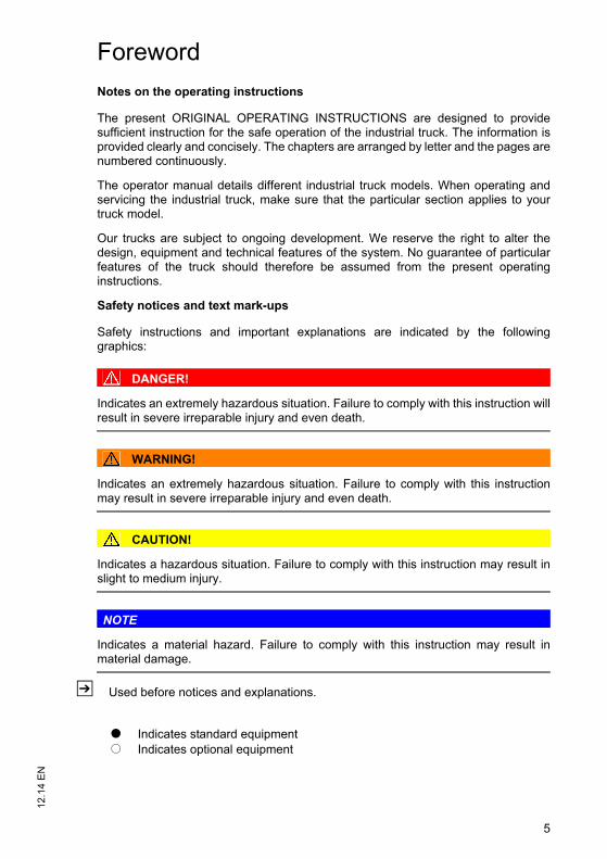
Safety notices and text mark-ups
Safety instructions and important explanations are indicated by the followinggraphics:
DANGER!
Indicates an extremely hazardous situation. Failure to comply with this instruction willresult in severe irreparable injury and even death.
WARNING!
Indicates an extremely hazardous situation. Failure to comply with this instructionmay result in severe irreparable injury and even death.
CAUTION!
Indicates a hazardous situation. Failure to comply with this instruction may result inslight to medium injury.
NOTE
Indicates a material hazard. Failure to comply with this instruction may result inmaterial damage.
Z Used before notices and explanations.
t Indicates standard equipmento Indicates optional equipment
5
12.1
4 E
N
Foreword
Notes on the operating instructions
The present ORIGINAL OPERATING INSTRUCTIONS are designed to providesufficient instruction for the safe operation of the industrial truck. The information isprovided clearly and concisely. The chapters are arranged by letter and the pages arenumbered continuously.
The operator manual details different industrial truck models. When operating andservicing the industrial truck, make sure that the particular section applies to yourtruck model.
Our trucks are subject to ongoing development. We reserve the right to alter thedesign, equipment and technical features of the system. No guarantee of particularfeatures of the truck should therefore be assumed from the present operatinginstructions.
Safety notices and text mark-ups
Safety instructions and important explanations are indicated by the followinggraphics:
DANGER!
Indicates an extremely hazardous situation. Failure to comply with this instruction willresult in severe irreparable injury and even death.
WARNING!
Indicates an extremely hazardous situation. Failure to comply with this instructionmay result in severe irreparable injury and even death.
CAUTION!
Indicates a hazardous situation. Failure to comply with this instruction may result inslight to medium injury.
NOTE
Indicates a material hazard. Failure to comply with this instruction may result inmaterial damage.
Z Used before notices and explanations.
t Indicates standard equipmento Indicates optional equipment

12.1
4 E
N
6
Copyright
Copyright of these operating instructions remains with JUNGHEINRICH AG.
Jungheinrich Aktiengesellschaft
Am Stadtrand 3522047 Hamburg - Germany
Tel: +49 (0) 40/6948-0
www.jungheinrich.com
12.1
4 E
N
6
Copyright
Copyright of these operating instructions remains with JUNGHEINRICH AG.
Jungheinrich Aktiengesellschaft
Am Stadtrand 3522047 Hamburg - Germany
Tel: +49 (0) 40/6948-0
www.jungheinrich.com
7
12.1
4 E
N
Contents
A Correct Use and Application ................................................... 11
1 General.................................................................................................... 112 Correct application................................................................................... 113 Approved application conditions.............................................................. 124 Proprietor responsibilities ........................................................................ 135 Adding attachments and/or optional equipment ...................................... 13
B Truck Description .................................................................... 15
1 Application ............................................................................................... 151.1 Truck models and rated capacity............................................................. 152 Travel direction definition......................................................................... 163 Assemblies and Functional Description................................................... 173.1 Assembly Overview ................................................................................. 173.2 Functional Description ............................................................................. 184 Technical Specifications .......................................................................... 194.1 Performance data .................................................................................... 194.2 Motor Output and Battery ........................................................................ 194.3 Weight ..................................................................................................... 194.4 Tyres........................................................................................................ 204.5 Dimensions.............................................................................................. 204.6 EN norms................................................................................................. 224.7 Conditions of use..................................................................................... 234.8 Electrical Requirements........................................................................... 235 Identification Points and Data Plates....................................................... 245.1 Indication Points ...................................................................................... 245.2 Data plate ................................................................................................ 255.3 Truck capacity plate................................................................................. 266 Wind loads............................................................................................... 26
C Transport and Commissioning ................................................ 27
1 Lifting by crane ........................................................................................ 272 Transport ................................................................................................. 293 Using the Truck for the First Time ........................................................... 30
D Battery - Servicing, Recharging, Replacement ....................... 31
1 Safety Regulations Governing the Handling of Lead-Acid Batteries ....... 312 Battery types............................................................................................ 333 Charging the battery ................................................................................ 343.1 Charging the Battery with an On-Board Charger..................................... 35
12.1
4 E
N
8
4 Battery removal and installation .............................................................. 374.1 Battery Replacement ............................................................................... 375 Battery Discharge Indicator / Hourmeter ................................................. 405.1 Battery Discharge Indicator ..................................................................... 405.2 Hourmeter................................................................................................ 40
E Operation ................................................................................ 41
1 Safety Regulations for the Operation of the Forklift Truck....................... 412 Displays and Controls.............................................................................. 433 Preparing the Truck for Operation ........................................................... 453.1 Checks and Operations to Be Performed Before Starting Daily Work .... 453.2 Preparing the truck for operation ............................................................. 463.3 Checks and operations to be carried out when the truck is operational .. 473.4 Parking the truck securely ....................................................................... 484 Industrial Truck Operation ....................................................................... 494.1 Safety regulations for truck operation...................................................... 494.2 Emergency Disconnect............................................................................ 514.3 Automatic braking.................................................................................... 534.4 Travel....................................................................................................... 534.5 Slow travel ............................................................................................... 554.6 Horn......................................................................................................... 554.7 Steering ................................................................................................... 564.8 Brakes ..................................................................................................... 564.9 Collision Safety Switch ............................................................................ 584.10 Load handler raise/lower ......................................................................... 594.11 Lifting, transporting and depositing loads ................................................ 615 Troubleshooting....................................................................................... 655.1 Truck does not start ................................................................................. 655.2 Load cannot be lifted ............................................................................... 666 Operating the truck without its own drive system .................................... 66
F Industrial Truck Maintenance .................................................. 67
1 Operational Safety and Environmental Protection................................... 672 Maintenance Safety Regulations............................................................. 682.1 Working on the electrical system............................................................. 692.2 Consumables and used parts.................................................................. 692.3 Wheels..................................................................................................... 692.4 Hydraulic system ..................................................................................... 703 Lubricants and Lubrication Schedule ...................................................... 713.1 Handling consumables safely .................................................................. 713.2 Lubrication Schedule ............................................................................... 733.3 Consumables........................................................................................... 744 Maintenance and repairs ......................................................................... 744.1 Preparing the truck for maintenance and repairs .................................... 744.2 Lifting and jacking up the truck safely...................................................... 754.3 Cleaning .................................................................................................. 764.4 Removing the Storage Compartment Panel............................................ 784.5 Front Cover Disassembly ........................................................................ 794.6 Opening the Instrument Panel ................................................................. 79
9
12.1
4 E
N4.7 Checking the hydraulic oil level ............................................................... 804.8 Checking electrical fuses......................................................................... 814.9 Restoring the truck to service after maintenance and repairs ................. 825 Decommissioning the Industrial Truck..................................................... 835.1 Prior to decommissioning ........................................................................ 835.2 Action to be Taken During Decommissioning.......................................... 835.3 Restoring the truck to service after decommissioning ............................. 846 Safety tests to be performed at intervals and after unusual incidents ..... 857 Final de-commissioning, disposal............................................................ 858 Human vibration measurement ............................................................... 859 Servicing and Inspection ......................................................................... 8610 Maintenance checklist ............................................................................. 87
9
12.1
4 E
N
4.7 Checking the hydraulic oil level ............................................................... 804.8 Checking electrical fuses......................................................................... 814.9 Restoring the truck to service after maintenance and repairs ................. 825 Decommissioning the Industrial Truck..................................................... 835.1 Prior to decommissioning ........................................................................ 835.2 Action to be Taken During Decommissioning.......................................... 835.3 Restoring the truck to service after decommissioning ............................. 846 Safety tests to be performed at intervals and after unusual incidents ..... 857 Final de-commissioning, disposal............................................................ 858 Human vibration measurement ............................................................... 859 Servicing and Inspection ......................................................................... 8610 Maintenance checklist ............................................................................. 87

12.1
4 E
N
10
12.1
4 E
N
10

1
0506
.GB
Appendix
JH Traction Battery Operating Instructions
Z These operating instructions apply only to Jungheinrich battery models. If usinganother brand, refer to the manufacturer's operating instructions.
1
0506
.GB
Appendix
JH Traction Battery Operating Instructions
Z These operating instructions apply only to Jungheinrich battery models. If usinganother brand, refer to the manufacturer's operating instructions.

0506
.GB
2
0506
.GB
2
11
12.1
4 E
N
A Correct Use and Application
1 General
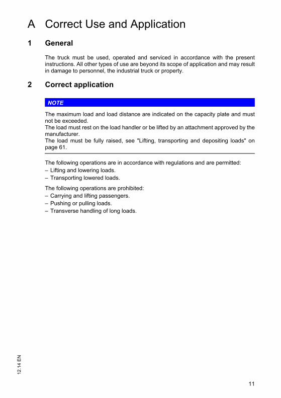
The truck must be used, operated and serviced in accordance with the presentinstructions. All other types of use are beyond its scope of application and may resultin damage to personnel, the industrial truck or property.
2 Correct application
NOTE
The maximum load and load distance are indicated on the capacity plate and mustnot be exceeded.The load must rest on the load handler or be lifted by an attachment approved by themanufacturer.The load must be fully raised, see "Lifting, transporting and depositing loads" onpage 61.
The following operations are in accordance with regulations and are permitted:– Lifting and lowering loads.– Transporting lowered loads.
The following operations are prohibited:– Carrying and lifting passengers.– Pushing or pulling loads.– Transverse handling of long loads.
11
12.1
4 E
N
A Correct Use and Application
1 General
The truck must be used, operated and serviced in accordance with the presentinstructions. All other types of use are beyond its scope of application and may resultin damage to personnel, the industrial truck or property.
2 Correct application
NOTE
The maximum load and load distance are indicated on the capacity plate and mustnot be exceeded.The load must rest on the load handler or be lifted by an attachment approved by themanufacturer.The load must be fully raised, see "Lifting, transporting and depositing loads" onpage 61.
The following operations are in accordance with regulations and are permitted:– Lifting and lowering loads.– Transporting lowered loads.
The following operations are prohibited:– Carrying and lifting passengers.– Pushing or pulling loads.– Transverse handling of long loads.
12.1
4 E
N
12
3 Approved application conditions
DANGER!
Do not exceed the permissible surface and point loading on the travel lanes.At blind spots get a second person to assist.The driver must ensure that the loading dock /dock leveller cannot be removed orcome loose during loading/unloading.
– Operation in industrial and commercial environments.– Permissible temperature range 5°C to 40°C.– Operation only on secure, level surfaces with sufficient capacity.– Do not exceed the permissible surface and spot load limits on the travel routes.– Operation only on routes that are visible and approved by the operating company.– Inclines of max. 5 % may be negotiated with load, and 8 % without load.– Do not travel across or at an angle on inclines. Travel with the load facing uphill.– Operation in partially public traffic.– Operation in workplaces with sufficient lighting (observe national regulations).
WARNING!
Use under extreme conditionsUsing the truck under extreme conditions can result in malfunctions and accidents.Special equipment and authorisation are required if the truck is to be constantly
used in extreme conditions, especially in dusty or corrosive atmospheres.The truck cannot be used in areas at risk of explosion. In adverse weather conditions (thunder, lightning) the industrial truck must not be
operated outside or in endangered areas.
13
12.1
4 E
N4 Proprietor responsibilities
For the purposes of the present operating instructions the “operating company” isdefined as any natural or legal person who either uses the industrial truck himself, oron whose behalf it is used. In special cases (e.g. leasing or renting) the proprietor isconsidered the person who, in accordance with existing contractual agreementsbetween the owner and user of the industrial truck, is charged with operational duties.The proprietor must ensure that the industrial truck is used only for the purpose it isintended for and that danger to life and limb of the user and third parties are excluded.Furthermore, accident prevention regulations, safety regulations and operating,servicing and repair guidelines must be followed. The operating company mustensure that all users have read and understood these operating instructions.
NOTE
Failure to comply with the operating instructions invalidates the warranty. The sameapplies if improper work is carried out on the truck by the customer or third partieswithout the permission of the manufacturer.
5 Adding attachments and/or optional equipment
The mounting or installation of additional equipment such as load backrests whichaffect or enhance the performance of the industrial truck requires the writtenpermission of the manufacturer. Local authority approval may also need to beobtained.Local authority approval however does not constitute the manufacturer’s approval.
13
12.1
4 E
N
4 Proprietor responsibilities
For the purposes of the present operating instructions the “operating company” isdefined as any natural or legal person who either uses the industrial truck himself, oron whose behalf it is used. In special cases (e.g. leasing or renting) the proprietor isconsidered the person who, in accordance with existing contractual agreementsbetween the owner and user of the industrial truck, is charged with operational duties.The proprietor must ensure that the industrial truck is used only for the purpose it isintended for and that danger to life and limb of the user and third parties are excluded.Furthermore, accident prevention regulations, safety regulations and operating,servicing and repair guidelines must be followed. The operating company mustensure that all users have read and understood these operating instructions.
NOTE
Failure to comply with the operating instructions invalidates the warranty. The sameapplies if improper work is carried out on the truck by the customer or third partieswithout the permission of the manufacturer.
5 Adding attachments and/or optional equipment
The mounting or installation of additional equipment such as load backrests whichaffect or enhance the performance of the industrial truck requires the writtenpermission of the manufacturer. Local authority approval may also need to beobtained.Local authority approval however does not constitute the manufacturer’s approval.

12.1
4 E
N
14
12.1
4 E
N
14
15
12.1
4 E
N
B Truck Description
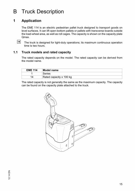
1 Application
The EME 114 is an electric pedestrian pallet truck designed to transport goods onlevel surfaces. It can lift open-bottom pallets or pallets with transverse boards outsidethe load-wheel area, as well as roll cages. The capacity is shown on the capacity plateQmax.
Z The truck is designed for light-duty operations; its maximum continuous operationtime is two hours.
1.1 Truck models and rated capacity
The rated capacity depends on the model. The rated capacity can be derived fromthe model name.
The rated capacity is not generally the same as the maximum capacity. The capacitycan be found on the capacity plate attached to the truck.
EME 114 Model name1 Series
14 Rated capacity x 100 kg
15
12.1
4 E
N
B Truck Description
1 Application
The EME 114 is an electric pedestrian pallet truck designed to transport goods onlevel surfaces. It can lift open-bottom pallets or pallets with transverse boards outsidethe load-wheel area, as well as roll cages. The capacity is shown on the capacity plateQmax.
Z The truck is designed for light-duty operations; its maximum continuous operationtime is two hours.
1.1 Truck models and rated capacity
The rated capacity depends on the model. The rated capacity can be derived fromthe model name.
The rated capacity is not generally the same as the maximum capacity. The capacitycan be found on the capacity plate attached to the truck.
EME 114 Model name1 Series
14 Rated capacity x 100 kg
12.1
4 E
N
16
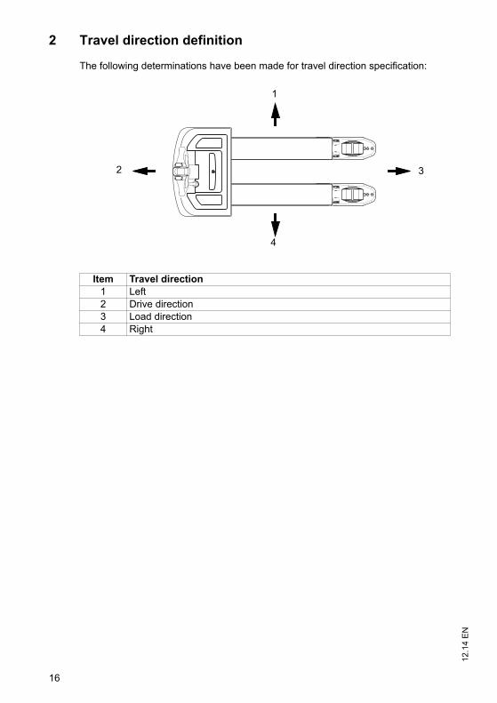
2 Travel direction definition
The following determinations have been made for travel direction specification:
Item Travel direction1 Left2 Drive direction3 Load direction4 Right
1
2 3
4
12.1
4 E
N
16
2 Travel direction definition
The following determinations have been made for travel direction specification:
Item Travel direction1 Left2 Drive direction3 Load direction4 Right
1
2 3
4
17
12.1
4 E
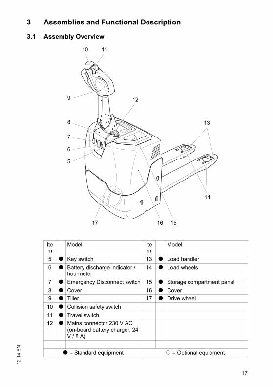
N3 Assemblies and Functional Description
3.1 Assembly Overview
Item
Model Item
Model
5 t Key switch 13 t Load handler
6 t Battery discharge indicator / hourmeter
14 t Load wheels
7 t Emergency Disconnect switch 15 t Storage compartment panel
8 t Cover 16 t Cover
9 t Tiller 17 t Drive wheel
10 t Collision safety switch
11 t Travel switch
12 t Mains connector 230 V AC (on-board battery charger, 24 V / 8 A)
t = Standard equipment o = Optional equipment
13
14
1516
12
1110
9
8
7
6
5
17
17
12.1
4 E
N
3 Assemblies and Functional Description
3.1 Assembly Overview
Item
Model Item
Model
5 t Key switch 13 t Load handler
6 t Battery discharge indicator / hourmeter
14 t Load wheels
7 t Emergency Disconnect switch 15 t Storage compartment panel
8 t Cover 16 t Cover
9 t Tiller 17 t Drive wheel
10 t Collision safety switch
11 t Travel switch
12 t Mains connector 230 V AC (on-board battery charger, 24 V / 8 A)
t = Standard equipment o = Optional equipment
13
14
1516
12
1110
9
8
7
6
5
17
12.1
4 E
N
18
3.2 Functional Description
Safety mechanisms
An enclosed, smooth truck geometry with rounded edges ensures safe handling ofthe truck. The wheels are surrounded by a solid skirt.
The 5 wheel chassis concept is based on 2 side cushioned support rollers on the sideplus a non-cushioned drive system. This improves tilt stability and the suspension.
Emergency Stop safety feature
Pressing the EMERGENCY DISCONNECT switch rapidly disconnects all electricalfunctions in hazardous situations. The safety collision switch prevents the operatorfrom being jammed between the truck and other objects. When applied, the truckmoves away from the operator.
Controls
All travel and lift functions can be performed without effort from the multi-function tillerhead. Rocker switches ensure consistently good operation in all tiller positions. Ahorn button is located in the middle of the tiller where it can be reached quickly.
Power Supply
The maintenance-free 63-Ah block batteries can be recharged simply by connectingthe integrated charger into any 230-V mains socket. The battery discharge indicatorshows the battery charge status and an integrated hourmeter the current service hourtotal.
Drive and brake system
The truck has a DC motor which enables travel speeds of up to 5 km/h. The truckdecelerates via an electromagnetic brake on the drive.
steering
The long tiller provides the operator with low stressing forces and a high safety factorat the same time.
Hydraulic System
Lifting and lowering are activated via rocker switches in the tiller arm. When lifting isactivated, the pump unit starts to operate, supplying hydraulic oil from the oil reservoirto the lift cylinder.
19
12.1
4 E
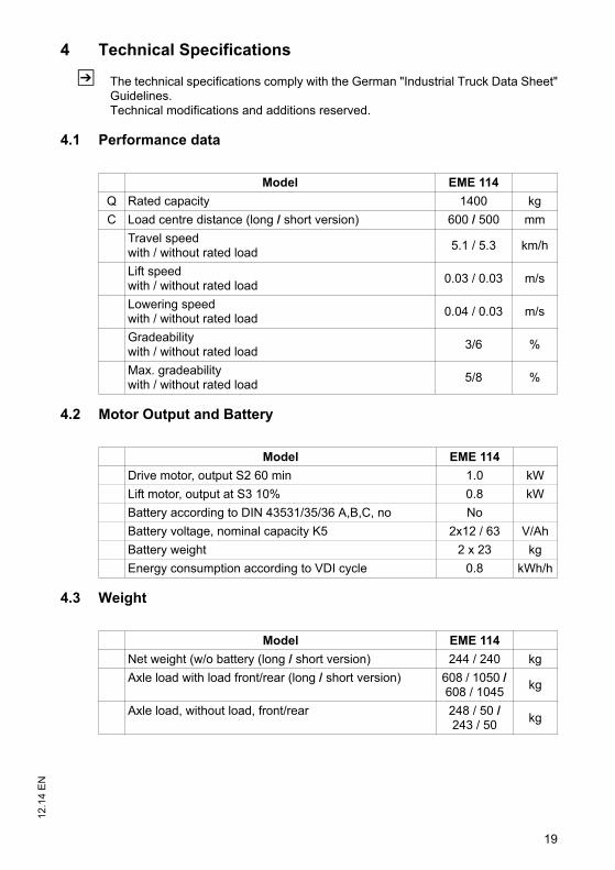
N4 Technical Specifications
Z The technical specifications comply with the German "Industrial Truck Data Sheet"Guidelines. Technical modifications and additions reserved.
4.1 Performance data
4.2 Motor Output and Battery
4.3 Weight
Model EME 114
Q Rated capacity 1400 kg
C Load centre distance (long / short version) 600 / 500 mm
Travel speedwith / without rated load
5.1 / 5.3 km/h
Lift speedwith / without rated load
0.03 / 0.03 m/s
Lowering speedwith / without rated load
0.04 / 0.03 m/s
Gradeabilitywith / without rated load
3/6 %
Max. gradeabilitywith / without rated load
5/8 %
Model EME 114
Drive motor, output S2 60 min 1.0 kW
Lift motor, output at S3 10% 0.8 kW
Battery according to DIN 43531/35/36 A,B,C, no No
Battery voltage, nominal capacity K5 2x12 / 63 V/Ah
Battery weight 2 x 23 kg
Energy consumption according to VDI cycle 0.8 kWh/h
Model EME 114
Net weight (w/o battery (long / short version) 244 / 240 kg
Axle load with load front/rear (long / short version) 608 / 1050 / 608 / 1045
kg
Axle load, without load, front/rear 248 / 50 / 243 / 50
kg
19
12.1
4 E
N
4 Technical Specifications
Z The technical specifications comply with the German "Industrial Truck Data Sheet"Guidelines. Technical modifications and additions reserved.
4.1 Performance data
4.2 Motor Output and Battery
4.3 Weight
Model EME 114
Q Rated capacity 1400 kg
C Load centre distance (long / short version) 600 / 500 mm
Travel speedwith / without rated load
5.1 / 5.3 km/h
Lift speedwith / without rated load
0.03 / 0.03 m/s
Lowering speedwith / without rated load
0.04 / 0.03 m/s
Gradeabilitywith / without rated load
3/6 %
Max. gradeabilitywith / without rated load
5/8 %
Model EME 114
Drive motor, output S2 60 min 1.0 kW
Lift motor, output at S3 10% 0.8 kW
Battery according to DIN 43531/35/36 A,B,C, no No
Battery voltage, nominal capacity K5 2x12 / 63 V/Ah
Battery weight 2 x 23 kg
Energy consumption according to VDI cycle 0.8 kWh/h
Model EME 114
Net weight (w/o battery (long / short version) 244 / 240 kg
Axle load with load front/rear (long / short version) 608 / 1050 / 608 / 1045
kg
Axle load, without load, front/rear 248 / 50 / 243 / 50
kg
12.1
4 E
N
20
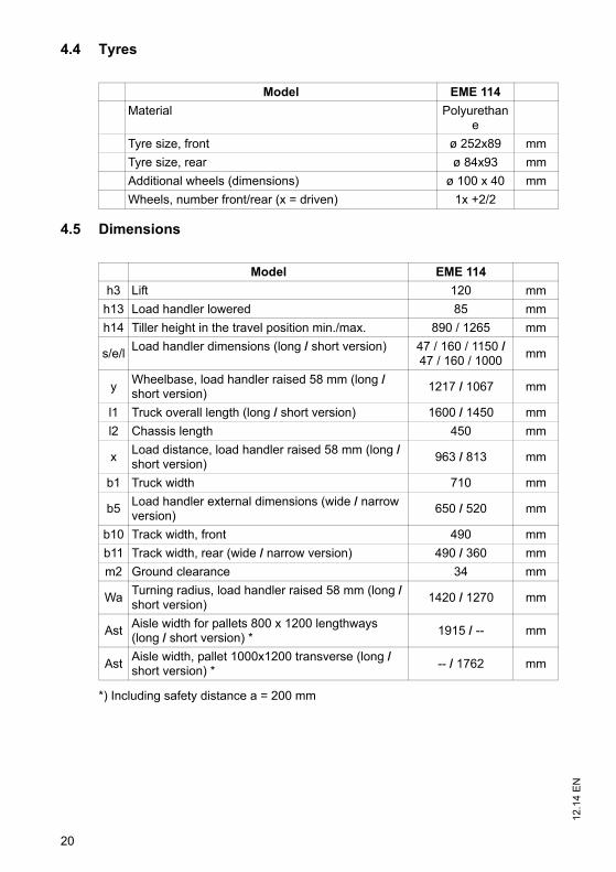
4.4 Tyres
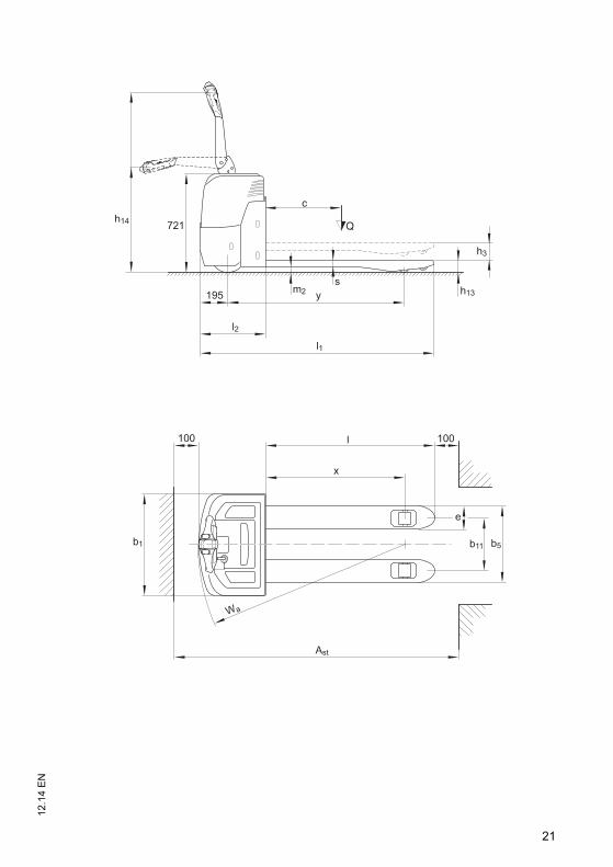
4.5 Dimensions
*) Including safety distance a = 200 mm
Model EME 114
Material Polyurethane
Tyre size, front ø 252x89 mm
Tyre size, rear ø 84x93 mm
Additional wheels (dimensions) ø 100 x 40 mm
Wheels, number front/rear (x = driven) 1x +2/2
Model EME 114
h3 Lift 120 mm
h13 Load handler lowered 85 mm
h14 Tiller height in the travel position min./max. 890 / 1265 mm
s/e/lLoad handler dimensions (long / short version) 47 / 160 / 1150 /
47 / 160 / 1000mm
yWheelbase, load handler raised 58 mm (long / short version)
1217 / 1067 mm
l1 Truck overall length (long / short version) 1600 / 1450 mm
l2 Chassis length 450 mm
xLoad distance, load handler raised 58 mm (long / short version)
963 / 813 mm
b1 Truck width 710 mm
b5Load handler external dimensions (wide / narrow version)
650 / 520 mm
b10 Track width, front 490 mm
b11 Track width, rear (wide / narrow version) 490 / 360 mm
m2 Ground clearance 34 mm
WaTurning radius, load handler raised 58 mm (long / short version)
1420 / 1270 mm
AstAisle width for pallets 800 x 1200 lengthways (long / short version) *
1915 / -- mm
AstAisle width, pallet 1000x1200 transverse (long / short version) *
-- / 1762 mm
12.1
4 E
N
20
4.4 Tyres
4.5 Dimensions
*) Including safety distance a = 200 mm
Model EME 114
Material Polyurethane
Tyre size, front ø 252x89 mm
Tyre size, rear ø 84x93 mm
Additional wheels (dimensions) ø 100 x 40 mm
Wheels, number front/rear (x = driven) 1x +2/2
Model EME 114
h3 Lift 120 mm
h13 Load handler lowered 85 mm
h14 Tiller height in the travel position min./max. 890 / 1265 mm
s/e/lLoad handler dimensions (long / short version) 47 / 160 / 1150 /
47 / 160 / 1000mm
yWheelbase, load handler raised 58 mm (long / short version)
1217 / 1067 mm
l1 Truck overall length (long / short version) 1600 / 1450 mm
l2 Chassis length 450 mm
xLoad distance, load handler raised 58 mm (long / short version)
963 / 813 mm
b1 Truck width 710 mm
b5Load handler external dimensions (wide / narrow version)
650 / 520 mm
b10 Track width, front 490 mm
b11 Track width, rear (wide / narrow version) 490 / 360 mm
m2 Ground clearance 34 mm
WaTurning radius, load handler raised 58 mm (long / short version)
1420 / 1270 mm
AstAisle width for pallets 800 x 1200 lengthways (long / short version) *
1915 / -- mm
AstAisle width, pallet 1000x1200 transverse (long / short version) *
-- / 1762 mm
21
12.1
4 E
N
721h14
h3
h13
l1
b11
Ast
Wa
c
Q
m2s
100
l2
195 y
100
e
l
x
b5b1
21
12.1
4 E
N
721h14
h3
h13
l1
b11
Ast
Wa
c
Q
m2s
100
l2
195 y
100
e
l
x
b5b1
12.1
4 E
N
22
4.6 EN norms
Noise emission level
– EME 114: 63 dB(A)
in accordance with EN 12053 as harmonised with ISO 4871.
Z The noise emission level is calculated in accordance with standard procedures andtakes into account the noise level when travelling, lifting and when idle. The noiselevel is measured at the level of the driver's ear.
Electromagnetic compatibility (EMC)
The manufacturer confirms that the truck adheres to the limits for electromagneticemissions and resistance as well as the static electricity discharge test in accordancewith EN 12895 as well as the standardised instructions contained therein.
Z No changes to electric or electronic components or their arrangement may bemade without the written agreement of the manufacturer.
WARNING!
Medical equipment can be damaged by non-ionised radiationElectrical equipment on the truck emitting non-ionised radiation (e.g. wireless datatransmission) can affect operators' medical equipment (pacemakers, hearing aidsetc.) and result in malfunctions. Consult a doctor or the manufacturer of the medicalequipment to clarify whether it can be used near the industrial truck.
23
12.1
4 E
N4.7 Conditions of use
Ambient temperature
– operating at 5°C to 40°C
Z Optimum battery useful life is achieved at battery temperatures of 15 to 35 °C. Lowtemperatures reduce the available battery capacity, high temperatures reduce thebattery useful life.
NOTE
45 °C is the maximum temperature for batteries, at which point the truck cannot beoperated. Special equipment and authorisation are required if the truck is to be usedcontinually in conditions of extreme temperature or condensing air humidityfluctuations.
4.8 Electrical Requirements
The manufacturer certifies compliance with the requirements for the design andmanufacture of electrical equipment, according to EN 1175 "Industrial Truck Safety -Electrical Requirements", provided the truck is used according to its purpose.
23
12.1
4 E
N
4.7 Conditions of use
Ambient temperature
– operating at 5°C to 40°C
Z Optimum battery useful life is achieved at battery temperatures of 15 to 35 °C. Lowtemperatures reduce the available battery capacity, high temperatures reduce thebattery useful life.
NOTE
45 °C is the maximum temperature for batteries, at which point the truck cannot beoperated. Special equipment and authorisation are required if the truck is to be usedcontinually in conditions of extreme temperature or condensing air humidityfluctuations.
4.8 Electrical Requirements
The manufacturer certifies compliance with the requirements for the design andmanufacture of electrical equipment, according to EN 1175 "Industrial Truck Safety -Electrical Requirements", provided the truck is used according to its purpose.
12.1
4 E
N
24
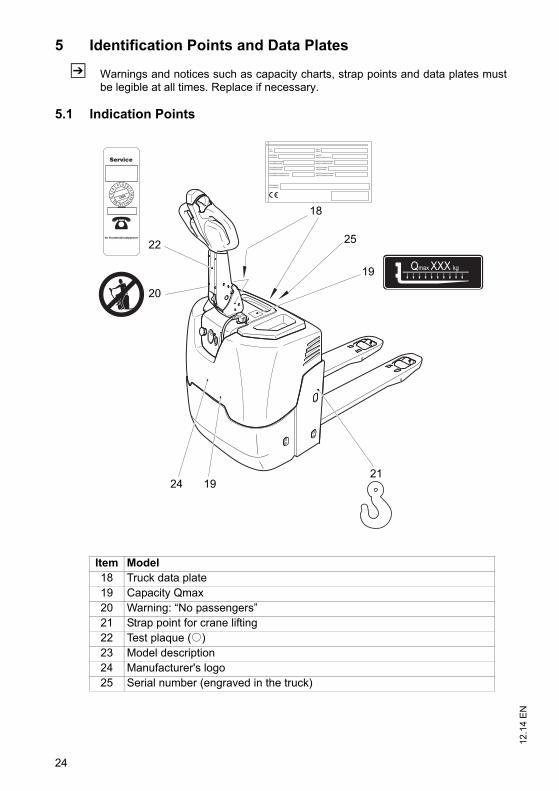
5 Identification Points and Data Plates
Z Warnings and notices such as capacity charts, strap points and data plates mustbe legible at all times. Replace if necessary.
5.1 Indication Points
Item Model18 Truck data plate19 Capacity Qmax20 Warning: “No passengers”21 Strap point for crane lifting22 Test plaque (o)23 Model description24 Manufacturer's logo25 Serial number (engraved in the truck)
Qmax XXX kg
18
20
22 25
19
211924
12.1
4 E
N
24
5 Identification Points and Data Plates
Z Warnings and notices such as capacity charts, strap points and data plates mustbe legible at all times. Replace if necessary.
5.1 Indication Points
Item Model18 Truck data plate19 Capacity Qmax20 Warning: “No passengers”21 Strap point for crane lifting22 Test plaque (o)23 Model description24 Manufacturer's logo25 Serial number (engraved in the truck)
Qmax XXX kg
18
20
22 25
19
211924
25
12.1
4 E
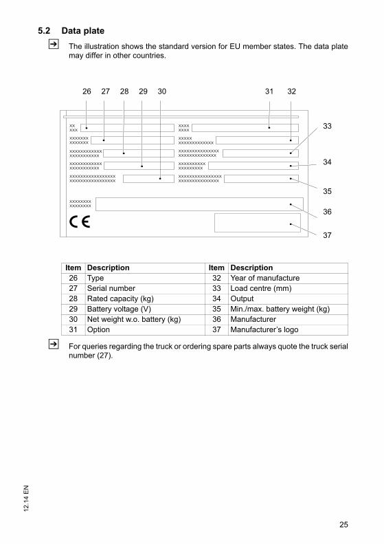
N5.2 Data plate
Z The illustration shows the standard version for EU member states. The data platemay differ in other countries.
Z For queries regarding the truck or ordering spare parts always quote the truck serialnumber (27).
26 27 2928 30
37
33
36
35
34
3231
Item Description Item Description26 Type 32 Year of manufacture27 Serial number 33 Load centre (mm)28 Rated capacity (kg) 34 Output29 Battery voltage (V) 35 Min./max. battery weight (kg)30 Net weight w.o. battery (kg) 36 Manufacturer31 Option 37 Manufacturer’s logo
25
12.1
4 E
N
5.2 Data plate
Z The illustration shows the standard version for EU member states. The data platemay differ in other countries.
Z For queries regarding the truck or ordering spare parts always quote the truck serialnumber (27).
26 27 2928 30
37
33
36
35
34
3231
Item Description Item Description26 Type 32 Year of manufacture27 Serial number 33 Load centre (mm)28 Rated capacity (kg) 34 Output29 Battery voltage (V) 35 Min./max. battery weight (kg)30 Net weight w.o. battery (kg) 36 Manufacturer31 Option 37 Manufacturer’s logo
12.1
4 E
N
26
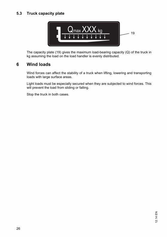
5.3 Truck capacity plate
The capacity plate (19) gives the maximum load-bearing capacity (Q) of the truck inkg assuming the load on the load handler is evenly distributed.
6 Wind loads
Wind forces can affect the stability of a truck when lifting, lowering and transportingloads with large surface areas.
Light loads must be especially secured when they are subjected to wind forces. Thiswill prevent the load from sliding or falling.
Stop the truck in both cases.
Qmax XXX kg19
12.1
4 E
N
26
5.3 Truck capacity plate
The capacity plate (19) gives the maximum load-bearing capacity (Q) of the truck inkg assuming the load on the load handler is evenly distributed.
6 Wind loads
Wind forces can affect the stability of a truck when lifting, lowering and transportingloads with large surface areas.
Light loads must be especially secured when they are subjected to wind forces. Thiswill prevent the load from sliding or falling.
Stop the truck in both cases.
Qmax XXX kg19
27
12.1
4 E
N
C Transport and Commissioning
1 Lifting by crane
WARNING!
All persons involved in loading by crane must be trainedIncorrect crane loading procedures due to untrained personnel can cause the truckto fall. There is a risk of injury to personnel and a risk of material damage to the truck.Loading must only be performed by specialist personnel trained for this purpose.
The specialist personnel must be instructed in securing loads on road vehicles andhandling load securing devices. In each case correct measurements must be takenand appropriate safety measures applied.
WARNING!
Incorrect lifting by crane can result in accidentsImproper use or use of unsuitable lifting gear and can cause the truck to fall whenbeing lifted by crane.Prevent the truck from hitting other objects during lifting, and avoid uncontrolledmovements. If necessary, secure the truck with guide ropes.The truck should only be loaded by personnel trained in the use of lifting slings and
tools.Wear personal protective equipment (e. g. safety shoes, safety helmet, hi-vis
jacket, protective gloves, etc.) when loading by crane.Do not stand under suspended loads.Do not enter or stand in a hazardous area.Always use lifting gear with sufficient capacity (for truck weight see truck rating
plate).Always attach the crane lifting gear to the prescribed strap points and prevent them
from slipping.Use the lifting slings only in the prescribed loading direction.Crane slings should be fastened in such a way that they do not come into contact
with any attachments when lifting.
12.1
4 E
N
28
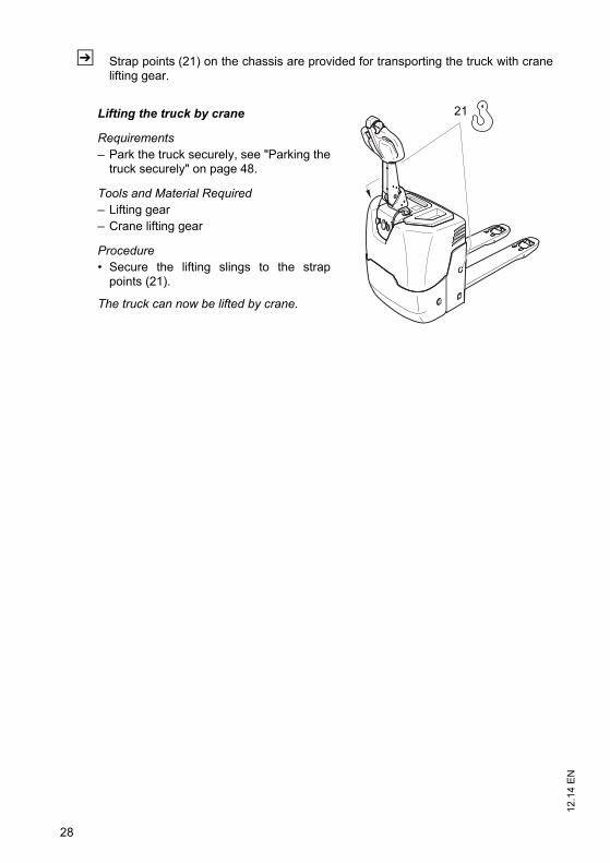
Z Strap points (21) on the chassis are provided for transporting the truck with cranelifting gear.
Lifting the truck by crane
Requirements– Park the truck securely, see "Parking the
truck securely" on page 48.
Tools and Material Required– Lifting gear– Crane lifting gear
Procedure• Secure the lifting slings to the strap
points (21).
The truck can now be lifted by crane.
21
12.1
4 E
N
28
Z Strap points (21) on the chassis are provided for transporting the truck with cranelifting gear.
Lifting the truck by crane
Requirements– Park the truck securely, see "Parking the
truck securely" on page 48.
Tools and Material Required– Lifting gear– Crane lifting gear
Procedure• Secure the lifting slings to the strap
points (21).
The truck can now be lifted by crane.
21
29
12.1
4 E
N2 Transport
WARNING!
Accidental movement during transportImproper fastening of the truck and mast during transport can result in seriousaccidents.Loading must only be performed by specialist personnel trained for this purpose.
The specialist personnel must be instructed in securing loads on road vehicles andhandling load securing devices. In each case correct measurements must be takenand appropriate safety measures applied.
The truck must be securely fastened when transported on a lorry or a trailer.The lorry or trailer must have fastening rings.Use wedges to prevent the truck from moving.Use only fastening belts with sufficient strength.Use non-slip materials to securing the load aids (pallet, wedges, ...) e. g. non-slip
mats.
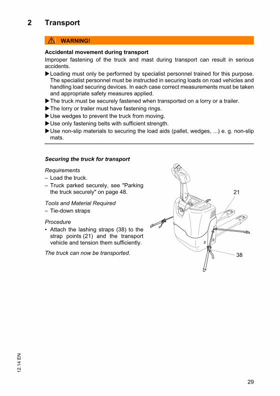
Securing the truck for transport
Requirements– Load the truck.– Truck parked securely, see "Parking
the truck securely" on page 48.
Tools and Material Required– Tie-down straps
Procedure• Attach the lashing straps (38) to the
strap points (21) and the transportvehicle and tension them sufficiently.
The truck can now be transported. 38
21
29
12.1
4 E
N
2 Transport
WARNING!
Accidental movement during transportImproper fastening of the truck and mast during transport can result in seriousaccidents.Loading must only be performed by specialist personnel trained for this purpose.
The specialist personnel must be instructed in securing loads on road vehicles andhandling load securing devices. In each case correct measurements must be takenand appropriate safety measures applied.
The truck must be securely fastened when transported on a lorry or a trailer.The lorry or trailer must have fastening rings.Use wedges to prevent the truck from moving.Use only fastening belts with sufficient strength.Use non-slip materials to securing the load aids (pallet, wedges, ...) e. g. non-slip
mats.
Securing the truck for transport
Requirements– Load the truck.– Truck parked securely, see "Parking
the truck securely" on page 48.
Tools and Material Required– Tie-down straps
Procedure• Attach the lashing straps (38) to the
strap points (21) and the transportvehicle and tension them sufficiently.
The truck can now be transported. 38
21
12.1
4 E
N
30
3 Using the Truck for the First Time
WARNING!
The use of unsuitable energy sources can be hazardousRectified AC current will damage the assemblies (controllers, sensors, motors etc.)of the electronic system.Unsuitable cable connections (too long, insufficient wire cross-section) to the battery(tow cables) can overheat, setting the truck and battery on fire.The truck must only be operated with battery current.Cable connections to the battery (tow leads) must be less than 6 m long and have
a minimum cross-section of 50 mm².
NOTE
Do not lift loads if the truck is operated via a tow lead with an external battery.
Procedure• Check the equipment is complete.• If necessary, install the battery, see "Battery removal and installation" on page 37.
Do not damage the battery cable.• Charge the battery, see "Charging the Battery with an On-Board Charger" on
page 35.Z The truck settings must match the battery model (if the customer is charging the
battery).• Check the hydraulic oil level and top up if necessary (see "Checking the hydraulic
oil level" on page 80).• Start up the truck (see "Preparing the truck for operation" on page 46).
Truck is operational.
Wheel flattening
If the truck has been parked for a long period, the wheel surfaces may tend to flatten.This flattening has a negative effect on the safety and stability of the truck. Once thetruck has covered a certain distance, the flattening will disappear.
31
12.1
4 E
N
D Battery - Servicing, Recharging, Replacement
1 Safety Regulations Governing the Handling of Lead-Acid Batteries
Maintenance personnel
Batteries may only be charged, serviced or replaced by trained personnel. Theseoperating instructions and the battery manufacturer's instructions must be observedwhen performing these operations.
Fire Protection
Do not smoke and avoid naked flames when handling batteries. Wherever anindustrial truck is parked for charging there must be no inflammable material orconsumables capable of creating sparks within a minimum distance of 2 m from thetruck. The room must be ventilated. Fire protection equipment must be available.
CAUTION!
The use of unsuitable fire protection equipment can result in scaldingExtinguishing fires with water can cause a reaction with the battery acid. This canresult in scalding from the acid.Use powder extinguishers.Never extinguish a burning battery with water.
Battery maintenance
The battery must be kept dry and clean. The terminals and cable shoes must beclean, secure and have a light coating of dielectric grease.
CAUTION!
Short circuits can result in fireDamaged cables can cause short circuits, setting the truck and battery on fire.Before closing the battery cover make sure that the battery cables are not
damaged.
Battery disposal
Batteries may only be disposed of in accordance with national environmentalprotection regulations or disposal laws. The manufacturer’s disposal instructionsmust be observed.
12.1
4 E
N
32
WARNING!
Batteries can be hazardousBatteries contain dissolved acid which is toxic and caustic. Above all avoid anycontact with battery acid.Always wear protective clothing and goggles when working with batteries.Do not let battery acid come into contact with skin, clothing or eyes. If necessary,
rinse with plenty of clean water.In the event of physical damage (e.g. skin or eye contact with battery acid) call for
a doctor immediately.Leaked battery acid should be neutralised immediately with plenty of water.Only batteries with a sealed battery container may be used.Follow national guidelines and legislation.
WARNING!
Unsuitable batteries that have not been approved by Jungheinrich for the truckcan be hazardousThe design, weight and dimensions of the battery have a considerable effect on theoperational safety of the truck, in particular its stability and capacity. The use ofunsuitable batteries that have not been approved for the truck by Jungheinrich, canlead to a deterioration of the braking characteristics of the truck during energyrecovery, causing considerable damage to the electric controller and resulting inserious danger to the health and safety of individuals.Only Jungheinrich-approved batteries may be used on the truck.Battery equipment may only be replaced with the agreement of Jungheinrich.When replacing/installing the battery make sure the battery is securely located in
the battery compartment of the truck.Do not use batteries that have not been approved by the manufacturer.
Park the truck securely before carrying out any work on the batteries (see "Parkingthe truck securely" on page 48).
33
12.1
4 E
N2 Battery types
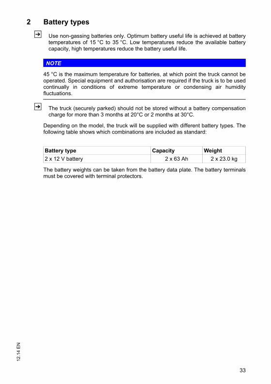
Z Use non-gassing batteries only. Optimum battery useful life is achieved at batterytemperatures of 15 °C to 35 °C. Low temperatures reduce the available batterycapacity, high temperatures reduce the battery useful life.
NOTE
45 °C is the maximum temperature for batteries, at which point the truck cannot beoperated. Special equipment and authorisation are required if the truck is to be usedcontinually in conditions of extreme temperature or condensing air humidityfluctuations.
Z The truck (securely parked) should not be stored without a battery compensationcharge for more than 3 months at 20°C or 2 months at 30°C.
Depending on the model, the truck will be supplied with different battery types. Thefollowing table shows which combinations are included as standard:
The battery weights can be taken from the battery data plate. The battery terminalsmust be covered with terminal protectors.
Battery type Capacity Weight
2 x 12 V battery 2 x 63 Ah 2 x 23.0 kg
33
12.1
4 E
N
2 Battery types
Z Use non-gassing batteries only. Optimum battery useful life is achieved at batterytemperatures of 15 °C to 35 °C. Low temperatures reduce the available batterycapacity, high temperatures reduce the battery useful life.
NOTE
45 °C is the maximum temperature for batteries, at which point the truck cannot beoperated. Special equipment and authorisation are required if the truck is to be usedcontinually in conditions of extreme temperature or condensing air humidityfluctuations.
Z The truck (securely parked) should not be stored without a battery compensationcharge for more than 3 months at 20°C or 2 months at 30°C.
Depending on the model, the truck will be supplied with different battery types. Thefollowing table shows which combinations are included as standard:
The battery weights can be taken from the battery data plate. The battery terminalsmust be covered with terminal protectors.
Battery type Capacity Weight
2 x 12 V battery 2 x 63 Ah 2 x 23.0 kg
12.1
4 E
N
34
3 Charging the battery
DANGER!
Risk of electric shock and burningDamaged and unsuitable cables can cause electric shocks and can overheat,resulting in fires.Always use mains cables with a maximum length of 30 m.
Local regulations must be observed.Unwind the cable reel fully when using it.Always use original manufacturer’s mains cables.Insulation safety, acid and caustic ratings must comply with the manufacturer's
mains lead.The mains plug must be dry and clean when used.
NOTE
Improper use of the charger can cause material damageThe charger, which consists of a battery charger and battery controller, must not beopened. If faulty, contact the manufacturer’s customer service department.The charger must only be used for batteries supplied by the manufacturer or other
approved batteries provided it has been adapted by the manufacturer's customerservice department.
The charger must never be swapped between different truck models.Do not connect the battery to two chargers simultaneously.
35
12.1
4 E
N3.1 Charging the Battery with an On-Board Charger
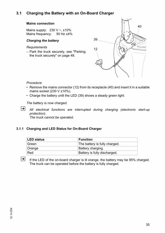
Mains connection
Mains supply: 230 V ~, ±10%Mains frequency: 50 Hz ±4%
Charging the battery
Requirements– Park the truck securely, see "Parking
the truck securely" on page 48.
Procedure• Remove the mains connector (12) from its receptacle (40) and insert it in a suitable
mains socket (230 V ±10%).• Charge the battery until the LED (39) shows a steady green light.
The battery is now charged.
Z All electrical functions are interrupted during charging (electronic start-upprotection).The truck cannot be operated.
3.1.1 Charging and LED Status for On-Board Charger
Z If the LED of the on-board charger is lit orange, the battery may be 95% charged.The truck can be operated before the battery is fully charged.
39
12
40
LED status FunctionGreen The battery is fully charged.Orange Battery charging.Red Battery is fully discharged.
35
12.1
4 E
N
3.1 Charging the Battery with an On-Board Charger
Mains connection
Mains supply: 230 V ~, ±10%Mains frequency: 50 Hz ±4%
Charging the battery
Requirements– Park the truck securely, see "Parking
the truck securely" on page 48.
Procedure• Remove the mains connector (12) from its receptacle (40) and insert it in a suitable
mains socket (230 V ±10%).• Charge the battery until the LED (39) shows a steady green light.
The battery is now charged.
Z All electrical functions are interrupted during charging (electronic start-upprotection).The truck cannot be operated.
3.1.1 Charging and LED Status for On-Board Charger
Z If the LED of the on-board charger is lit orange, the battery may be 95% charged.The truck can be operated before the battery is fully charged.
39
12
40
LED status FunctionGreen The battery is fully charged.Orange Battery charging.Red Battery is fully discharged.
12.1
4 E
N
36
3.1.2 Checking the Charge Status
Z The exact charge status is shown in the battery discharge indicator.
Procedure• Interrupt the charge by removing the connector (12) from the mains socket and
insert it in its receptacle (40).• Start up the truck, see Switching on the Truck in Chapter E.• Check the charge status on the battery discharge indicator, see battery discharge
indicator/hourmeter in Section 5.• Continue charging if necessary.
3.1.3 Trickle Charge
When the battery is fully charged the charger then switches to compensation charge.The compensation charge lasts until the mains connector is removed.
Z To ensure a long battery life, it is advisable to run regular compensation charges(every 1-2 weeks).
3.1.4 Partial Charging
The charger is designed to automatically adapt to partially charged batteries. Thiskeeps battery wear to a minimum.
3.1.5 Completing Battery Charging, Restoring the Truck to Operation
NOTE
If charging has been interrupted, the full battery capacity will not be available.
Procedure• Remove the mains connector from the mains socket and insert it in the receptacle
(40).
37
12.1
4 E
N4 Battery removal and installation
WARNING!
Accident risk during battery removal and installationDue to the battery weight and acid there is a risk of trapping or acid burns when thebattery is removed and installed.Note the "Safety regulations for handling acid batteries" section in this chapter.Wear safety shoes when removing and installing the battery.Park the truck on a horizontal surface.Make sure the battery is located securely in the truck's battery compartment.
CAUTION!
Trapping hazardThere is a risk of trapping when you close the battery cover.Make sure there is nothing between the battery cover and the truck when you close
the battery cover.
4.1 Battery Replacement
NOTE
To avoid damaging electrical components, first disconnect both negative terminals(blue) from the batteries.
Z Removal and assembly of the left and right batteries is identical.
Removing the Battery
Requirements– Park the truck securely, see page 48.
37
12.1
4 E
N
4 Battery removal and installation
WARNING!
Accident risk during battery removal and installationDue to the battery weight and acid there is a risk of trapping or acid burns when thebattery is removed and installed.Note the "Safety regulations for handling acid batteries" section in this chapter.Wear safety shoes when removing and installing the battery.Park the truck on a horizontal surface.Make sure the battery is located securely in the truck's battery compartment.
CAUTION!
Trapping hazardThere is a risk of trapping when you close the battery cover.Make sure there is nothing between the battery cover and the truck when you close
the battery cover.
4.1 Battery Replacement
NOTE
To avoid damaging electrical components, first disconnect both negative terminals(blue) from the batteries.
Z Removal and assembly of the left and right batteries is identical.
Removing the Battery
Requirements– Park the truck securely, see page 48.
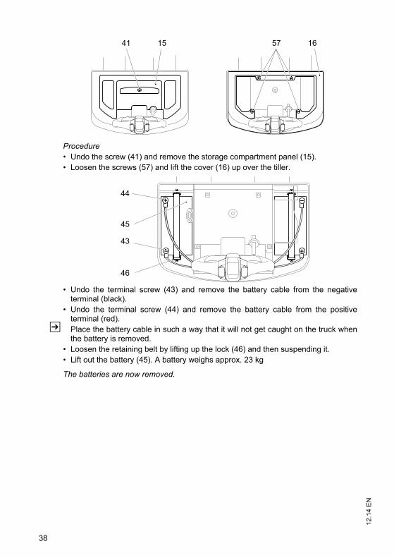
12.1
4 E
N
38
Procedure• Undo the screw (41) and remove the storage compartment panel (15).• Loosen the screws (57) and lift the cover (16) up over the tiller.•
• Undo the terminal screw (43) and remove the battery cable from the negativeterminal (black).
• Undo the terminal screw (44) and remove the battery cable from the positiveterminal (red).
Z Place the battery cable in such a way that it will not get caught on the truck whenthe battery is removed.
• Loosen the retaining belt by lifting up the lock (46) and then suspending it.• Lift out the battery (45). A battery weighs approx. 23 kg
The batteries are now removed.
41 15 57 16
43
44
45
46
39
12.1
4 E
N
Battery installation
ProcedureZ Installation is in the reverse order of removal. When reinstalling the battery, make
sure the battery is securely mounted and connected correctly.• Connect the positive battery terminals (red) first and then the battery cables of the
negative terminal (black).
CAUTION!Trapping hazardThere is a risk of trapping when you fit the panel.
• Install the panel, see "Preparing the truck for maintenance and repairs" on page 74.
The batteries are now installed.
Z After installing the battery again, check all cables and plug connections for visiblesigns of damage.
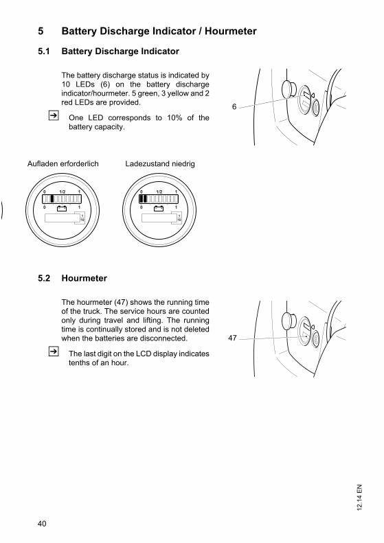
12.1
4 E
N
40
5 Battery Discharge Indicator / Hourmeter
5.1 Battery Discharge Indicator
The battery discharge status is indicated by10 LEDs (6) on the battery dischargeindicator/hourmeter. 5 green, 3 yellow and 2red LEDs are provided.
Z One LED corresponds to 10% of thebattery capacity.
5.2 Hourmeter
The hourmeter (47) shows the running timeof the truck. The service hours are countedonly during travel and lifting. The runningtime is continually stored and is not deletedwhen the batteries are disconnected.
Z The last digit on the LCD display indicatestenths of an hour.
6
Aufladen erforderlich Ladezustand niedrig
47
41
12.1
4 E
N
E Operation
1 Safety Regulations for the Operation of theForklift Truck
Driver authorisation
The truck may only be used by suitably trained personnel, who have demonstrated tothe proprietor or his representative that they can drive and handle loads and havebeen authorised to operate the truck by the proprietor or his representative.
Operator’s rights, responsibilities and rules of conduct
The driver must be informed of his duties and responsibilities and be instructed in theoperation of the truck and shall be familiar with the operating instructions. Safetyshoes must be worn on pedestrian-operated trucks.
Unauthorised use of truck
The operator is responsible for the truck during the time it is in use. The operator mustprevent unauthorised persons from driving or operating the truck. Do not carrypassengers or lift other people.
Damage and faults
The supervisor must be informed immediately of any damage or faults to the truck orattachment. Trucks which are unsafe for operation (e.g. wheel or brake problems)must not be used until they have been rectified.
Repairs
The operator must not carry out any repairs or alterations to the truck withoutauthorisation and the necessary training to do so. The operator must never disable oradjust safety mechanisms or switches.
Hazardous area
WARNING!
Risk of accidents/injury in the hazardous area of the truck A hazardous area is defined as the area in which people are at risk due to travel orlifting operations of the truck, its load handler or the load. This also includes the areawithin reach of falling loads or lowering/falling operating equipment.Instruct unauthorised persons to leave the hazardous area.In case of danger to third parties, give a warning signal in good time.If unauthorised persons are still within the hazardous area, stop the truck
immediately.
Safety devices, warning signs and warning instructions
Safety devices, warning signs (see "Identification Points and Data Plates" onpage 24) and warning instructions in the present operating instructions must bestrictly observed.
12.1
4 E
N
42
WARNING!
Removing or disabling safety devices can cause accidentsRemoving or disabling safety devices such as the emergency disconnect switch, keyswitch, buttons, horn, strobe lights, sensors, panels, etc. can result in accidents andinjury.Report any defects immediately to your supervisor.Mark defective truck and take it out of service.Do not return the truck to service until you have identified and rectified the fault.
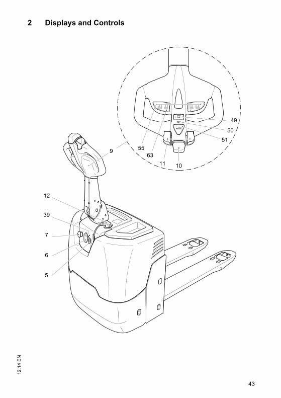
43
12.1
4 E
N2 Displays and Controls
11
51
50
49
6355
5
6
7
39
12
9
10
43
12.1
4 E
N
2 Displays and Controls
11
51
50
49
6355
5
6
7
39
12
9
10
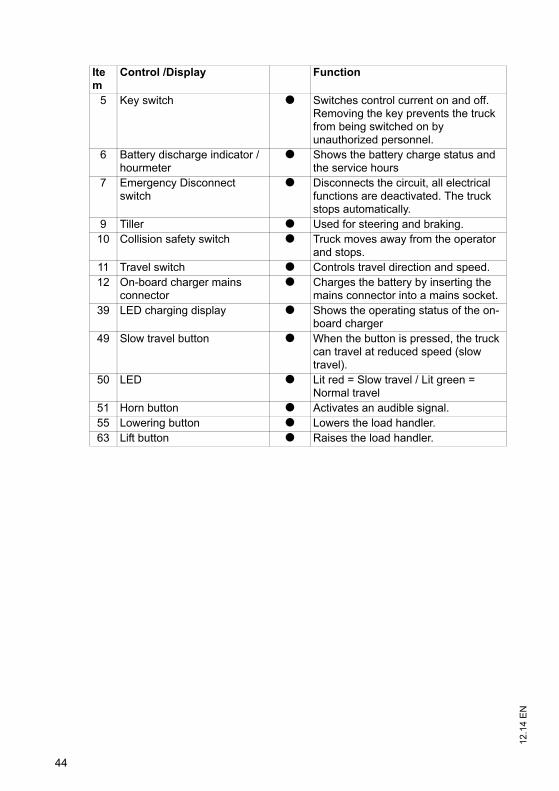
12.1
4 E
N
44
Item
Control /Display Function
5 Key switch t Switches control current on and off. Removing the key prevents the truck from being switched on by unauthorized personnel.
6 Battery discharge indicator / hourmeter
t Shows the battery charge status and the service hours
7 Emergency Disconnect switch
t Disconnects the circuit, all electrical functions are deactivated. The truck stops automatically.
9 Tiller t Used for steering and braking.10 Collision safety switch t Truck moves away from the operator
and stops.11 Travel switch t Controls travel direction and speed.12 On-board charger mains
connectort Charges the battery by inserting the
mains connector into a mains socket.39 LED charging display t Shows the operating status of the on-
board charger49 Slow travel button t When the button is pressed, the truck
can travel at reduced speed (slow travel).
50 LED t Lit red = Slow travel / Lit green = Normal travel
51 Horn button t Activates an audible signal.55 Lowering button t Lowers the load handler.63 Lift button t Raises the load handler.
45
12.1
4 E
N3 Preparing the Truck for Operation
3.1 Checks and Operations to Be Performed Before Starting Daily Work
WARNING!
Risk of accident due to damage to or other defects in the truck and optionalfeaturesIf damage or other truck or attachment (optional equipment) defects are discoveredduring the following checks, the truck must be taken out of service until it has beenrepaired.Report any defects immediately to your supervisor.Mark defective truck and take out of service.Do not return the industrial truck to service until you have identified and rectified the
fault.
Inspection before daily operation
Procedure• Check the whole of the outside of the truck for signs of damage and leaks.
Damaged hoses must be replaced immediately.• Check the battery attachment and wire connections for damage and make sure
they are secure.• Check the load handler for visible signs of damage such as cracks, bent or severely
worn forks.• Check the drive wheel and load wheels for damage.• Check that the markings and labels are present, clean and legible, see
"Identification Points and Data Plates" on page 24.• Test the emergency disconnect switch.• Check the tiller (damper) is restored to its normal position.• Check the controls are automatically restored to zero after being applied.• Test the brakes.• Make sure the drive panel and covers are secure and check for damage.
45
12.1
4 E
N
3 Preparing the Truck for Operation
3.1 Checks and Operations to Be Performed Before Starting Daily Work
WARNING!
Risk of accident due to damage to or other defects in the truck and optionalfeaturesIf damage or other truck or attachment (optional equipment) defects are discoveredduring the following checks, the truck must be taken out of service until it has beenrepaired.Report any defects immediately to your supervisor.Mark defective truck and take out of service.Do not return the industrial truck to service until you have identified and rectified the
fault.
Inspection before daily operation
Procedure• Check the whole of the outside of the truck for signs of damage and leaks.
Damaged hoses must be replaced immediately.• Check the battery attachment and wire connections for damage and make sure
they are secure.• Check the load handler for visible signs of damage such as cracks, bent or severely
worn forks.• Check the drive wheel and load wheels for damage.• Check that the markings and labels are present, clean and legible, see
"Identification Points and Data Plates" on page 24.• Test the emergency disconnect switch.• Check the tiller (damper) is restored to its normal position.• Check the controls are automatically restored to zero after being applied.• Test the brakes.• Make sure the drive panel and covers are secure and check for damage.
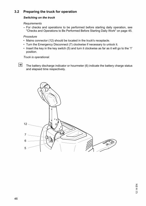
12.1
4 E
N
46
3.2 Preparing the truck for operation
Switching on the truck
Requirements– For checks and operations to be performed before starting daily operation, see
"Checks and Operations to Be Performed Before Starting Daily Work" on page 45.
Procedure• Mains connector (12) should be located in the truck's receptacle.• Turn the Emergency Disconnect (7) clockwise if necessary to unlock it.• Insert the key in the key switch (5) and turn it clockwise as far as it will go to the “I”
position.
Truck is operational.
Z The battery discharge indicator or hourmeter (6) indicate the battery charge statusand elapsed time respectively.
5
6
7
12
47
12.1
4 E
N3.3 Checks and operations to be carried out when the truck is
operational
WARNING!
Risk of accident due to damage to or other defects in the truck and optionalfeaturesIf damage or other truck or attachment (optional equipment) defects are discoveredduring the following checks, the truck must be taken out of service until it has beenrepaired.Report any defects immediately to your supervisor.Mark defective truck and take out of service.Do not return the industrial truck to service until you have identified and rectified the
fault.
Procedure• Test warning indicators and safety devices:
• Test the emergency disconnect function by pressing the emergency disconnectswitch. The main circuit is disconnected and no truck operations can beperformed. Now turn anti-clockwise to unlock it.
• Test the horn by pressing the "warning signal" button.• Check braking efficiency, see "Brakes" on page 56.• Test the steering, see "Steering" on page 56.• Test the hydraulic system, see "Load handler raise/lower" on page 59.• Test travel operations, see "Travel" on page 53.• Test the "collision safety switch" by depressing it whilst driving in the drive
direction.• Test the controls and displays and check for damage, see "Displays and Controls"
on page 43.• Check tiller return function.• Check the controls automatically return to the neutral position after use.
47
12.1
4 E
N
3.3 Checks and operations to be carried out when the truck is operational
WARNING!
Risk of accident due to damage to or other defects in the truck and optionalfeaturesIf damage or other truck or attachment (optional equipment) defects are discoveredduring the following checks, the truck must be taken out of service until it has beenrepaired.Report any defects immediately to your supervisor.Mark defective truck and take out of service.Do not return the industrial truck to service until you have identified and rectified the
fault.
Procedure• Test warning indicators and safety devices:
• Test the emergency disconnect function by pressing the emergency disconnectswitch. The main circuit is disconnected and no truck operations can beperformed. Now turn anti-clockwise to unlock it.
• Test the horn by pressing the "warning signal" button.• Check braking efficiency, see "Brakes" on page 56.• Test the steering, see "Steering" on page 56.• Test the hydraulic system, see "Load handler raise/lower" on page 59.• Test travel operations, see "Travel" on page 53.• Test the "collision safety switch" by depressing it whilst driving in the drive
direction.• Test the controls and displays and check for damage, see "Displays and Controls"
on page 43.• Check tiller return function.• Check the controls automatically return to the neutral position after use.
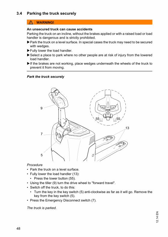
12.1
4 E
N
48
3.4 Parking the truck securely
WARNING!
An unsecured truck can cause accidentsParking the truck on an incline, without the brakes applied or with a raised load or loadhandler is dangerous and is strictly prohibited.Park the truck on a level surface. In special cases the truck may need to be secured
with wedges.Fully lower the load handler.Select a place to park where no other people are at risk of injury from the lowered
load handler. If the brakes are not working, place wedges underneath the wheels of the truck to
prevent it from moving.
Park the truck securely
Procedure• Park the truck on a level surface.• Fully lower the load handler (13):
• Press the lower button (55).• Using the tiller (9) turn the drive wheel to "forward travel".• Switch off the truck, to do this:
• Turn the key in the key switch (5) anti-clockwise as far as it will go. Remove thekey from the key switch (5).
• Press the Emergency Disconnect switch (7).
The truck is parked.
13
55
9
5
55
7
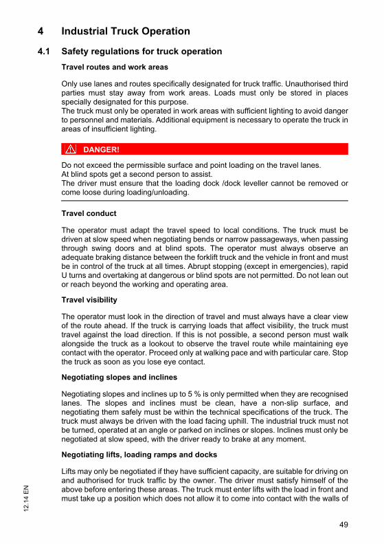
49
12.1
4 E
N4 Industrial Truck Operation
4.1 Safety regulations for truck operation
Travel routes and work areas
Only use lanes and routes specifically designated for truck traffic. Unauthorised thirdparties must stay away from work areas. Loads must only be stored in placesspecially designated for this purpose.The truck must only be operated in work areas with sufficient lighting to avoid dangerto personnel and materials. Additional equipment is necessary to operate the truck inareas of insufficient lighting.
DANGER!
Do not exceed the permissible surface and point loading on the travel lanes.At blind spots get a second person to assist.The driver must ensure that the loading dock /dock leveller cannot be removed orcome loose during loading/unloading.
Travel conduct
The operator must adapt the travel speed to local conditions. The truck must bedriven at slow speed when negotiating bends or narrow passageways, when passingthrough swing doors and at blind spots. The operator must always observe anadequate braking distance between the forklift truck and the vehicle in front and mustbe in control of the truck at all times. Abrupt stopping (except in emergencies), rapidU turns and overtaking at dangerous or blind spots are not permitted. Do not lean outor reach beyond the working and operating area.
Travel visibility
The operator must look in the direction of travel and must always have a clear viewof the route ahead. If the truck is carrying loads that affect visibility, the truck musttravel against the load direction. If this is not possible, a second person must walkalongside the truck as a lookout to observe the travel route while maintaining eyecontact with the operator. Proceed only at walking pace and with particular care. Stopthe truck as soon as you lose eye contact.
Negotiating slopes and inclines
Negotiating slopes and inclines up to 5 % is only permitted when they are recognisedlanes. The slopes and inclines must be clean, have a non-slip surface, andnegotiating them safely must be within the technical specifications of the truck. Thetruck must always be driven with the load facing uphill. The industrial truck must notbe turned, operated at an angle or parked on inclines or slopes. Inclines must only benegotiated at slow speed, with the driver ready to brake at any moment.
Negotiating lifts, loading ramps and docks
Lifts may only be negotiated if they have sufficient capacity, are suitable for driving onand authorised for truck traffic by the owner. The driver must satisfy himself of theabove before entering these areas. The truck must enter lifts with the load in front andmust take up a position which does not allow it to come into contact with the walls of
49
12.1
4 E
N
4 Industrial Truck Operation
4.1 Safety regulations for truck operation
Travel routes and work areas
Only use lanes and routes specifically designated for truck traffic. Unauthorised thirdparties must stay away from work areas. Loads must only be stored in placesspecially designated for this purpose.The truck must only be operated in work areas with sufficient lighting to avoid dangerto personnel and materials. Additional equipment is necessary to operate the truck inareas of insufficient lighting.
DANGER!
Do not exceed the permissible surface and point loading on the travel lanes.At blind spots get a second person to assist.The driver must ensure that the loading dock /dock leveller cannot be removed orcome loose during loading/unloading.
Travel conduct
The operator must adapt the travel speed to local conditions. The truck must bedriven at slow speed when negotiating bends or narrow passageways, when passingthrough swing doors and at blind spots. The operator must always observe anadequate braking distance between the forklift truck and the vehicle in front and mustbe in control of the truck at all times. Abrupt stopping (except in emergencies), rapidU turns and overtaking at dangerous or blind spots are not permitted. Do not lean outor reach beyond the working and operating area.
Travel visibility
The operator must look in the direction of travel and must always have a clear viewof the route ahead. If the truck is carrying loads that affect visibility, the truck musttravel against the load direction. If this is not possible, a second person must walkalongside the truck as a lookout to observe the travel route while maintaining eyecontact with the operator. Proceed only at walking pace and with particular care. Stopthe truck as soon as you lose eye contact.
Negotiating slopes and inclines
Negotiating slopes and inclines up to 5 % is only permitted when they are recognisedlanes. The slopes and inclines must be clean, have a non-slip surface, andnegotiating them safely must be within the technical specifications of the truck. Thetruck must always be driven with the load facing uphill. The industrial truck must notbe turned, operated at an angle or parked on inclines or slopes. Inclines must only benegotiated at slow speed, with the driver ready to brake at any moment.
Negotiating lifts, loading ramps and docks
Lifts may only be negotiated if they have sufficient capacity, are suitable for driving onand authorised for truck traffic by the owner. The driver must satisfy himself of theabove before entering these areas. The truck must enter lifts with the load in front andmust take up a position which does not allow it to come into contact with the walls of
12.1
4 E
N
50
the lift shaft. Persons riding in the lift with the forklift truck must only enter the lift afterthe truck has come to a rest and must leave the lift before the truck. The driver mustensure that the loading ramp / dock cannot move or come loose during loading /unloading.
Type of loads to be carried
The operator must make sure that the load is in a satisfactory condition. Loads mustalways be positioned safely and carefully. Use suitable precautions to prevent partsof the load from tipping or falling down. Prevent liquid loads from sloshing out.
WARNING!
Electromagnetic influence can result in accidentsStrong magnets can cause electronic components such as Hall sensors to becomedamaged, resulting in accidents.Do not use magnets in the operating area of the truck. Exceptions to this rule are
commercial, weak clamping magnets for attaching notices.
51
12.1
4 E
N4.2 Emergency Disconnect
CAUTION!
Applying maximum braking can result in accidentsApplying the Emergency Disconnect switch during travel will cause the truck todecelerate to a halt at maximum force. This may cause the load to slide off the loadhandler. There is a higher risk of accidents and injury.Do not use the Emergency Disconnect switch as a service brake.Use the Emergency Disconnect switch during travel only in emergencies.
CAUTION!
Faulty or non-accessible Emergency Disconnect switches can cause accidentsA faulty or non-accessible Emergency Disconnect switch can cause accidents. Indangerous situations the operator cannot bring the truck to a halt in time by applyingthe Emergency Disconnect switch. The operation of the Emergency Disconnect switch must not be affected by any
objects placed in its way.Report any defects on the Emergency Disconnect switch immediately to your
supervisor.Mark defective truck and take out of service.Do not return the industrial truck to service until you have identified and rectified the
fault.
51
12.1
4 E
N
4.2 Emergency Disconnect
CAUTION!
Applying maximum braking can result in accidentsApplying the Emergency Disconnect switch during travel will cause the truck todecelerate to a halt at maximum force. This may cause the load to slide off the loadhandler. There is a higher risk of accidents and injury.Do not use the Emergency Disconnect switch as a service brake.Use the Emergency Disconnect switch during travel only in emergencies.
CAUTION!
Faulty or non-accessible Emergency Disconnect switches can cause accidentsA faulty or non-accessible Emergency Disconnect switch can cause accidents. Indangerous situations the operator cannot bring the truck to a halt in time by applyingthe Emergency Disconnect switch. The operation of the Emergency Disconnect switch must not be affected by any
objects placed in its way.Report any defects on the Emergency Disconnect switch immediately to your
supervisor.Mark defective truck and take out of service.Do not return the industrial truck to service until you have identified and rectified the
fault.
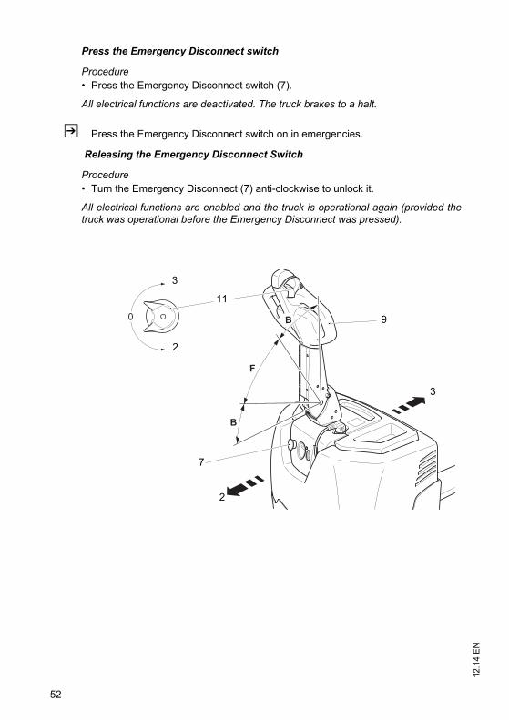
12.1
4 E
N
52
Press the Emergency Disconnect switch
Procedure• Press the Emergency Disconnect switch (7).
All electrical functions are deactivated. The truck brakes to a halt.
Z Press the Emergency Disconnect switch on in emergencies.
Releasing the Emergency Disconnect Switch
Procedure• Turn the Emergency Disconnect (7) anti-clockwise to unlock it.
All electrical functions are enabled and the truck is operational again (provided thetruck was operational before the Emergency Disconnect was pressed).
0 B
F
B
9
11
7
3
2
3
2
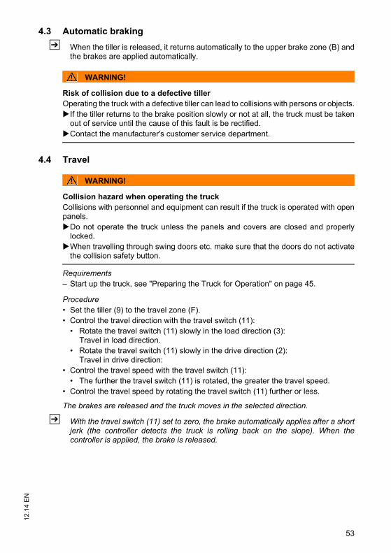
53
12.1
4 E
N4.3 Automatic braking
Z When the tiller is released, it returns automatically to the upper brake zone (B) andthe brakes are applied automatically.
WARNING!
Risk of collision due to a defective tillerOperating the truck with a defective tiller can lead to collisions with persons or objects.If the tiller returns to the brake position slowly or not at all, the truck must be taken
out of service until the cause of this fault is be rectified. Contact the manufacturer's customer service department.
4.4 Travel
WARNING!
Collision hazard when operating the truckCollisions with personnel and equipment can result if the truck is operated with openpanels.Do not operate the truck unless the panels and covers are closed and properly
locked.When travelling through swing doors etc. make sure that the doors do not activate
the collision safety button.
Requirements– Start up the truck, see "Preparing the Truck for Operation" on page 45.
Procedure• Set the tiller (9) to the travel zone (F).• Control the travel direction with the travel switch (11):
• Rotate the travel switch (11) slowly in the load direction (3):Travel in load direction.
• Rotate the travel switch (11) slowly in the drive direction (2):Travel in drive direction:
• Control the travel speed with the travel switch (11):• The further the travel switch (11) is rotated, the greater the travel speed.
• Control the travel speed by rotating the travel switch (11) further or less.
The brakes are released and the truck moves in the selected direction.
Z With the travel switch (11) set to zero, the brake automatically applies after a shortjerk (the controller detects the truck is rolling back on the slope). When thecontroller is applied, the brake is released.
53
12.1
4 E
N
4.3 Automatic braking
Z When the tiller is released, it returns automatically to the upper brake zone (B) andthe brakes are applied automatically.
WARNING!
Risk of collision due to a defective tillerOperating the truck with a defective tiller can lead to collisions with persons or objects.If the tiller returns to the brake position slowly or not at all, the truck must be taken
out of service until the cause of this fault is be rectified. Contact the manufacturer's customer service department.
4.4 Travel
WARNING!
Collision hazard when operating the truckCollisions with personnel and equipment can result if the truck is operated with openpanels.Do not operate the truck unless the panels and covers are closed and properly
locked.When travelling through swing doors etc. make sure that the doors do not activate
the collision safety button.
Requirements– Start up the truck, see "Preparing the Truck for Operation" on page 45.
Procedure• Set the tiller (9) to the travel zone (F).• Control the travel direction with the travel switch (11):
• Rotate the travel switch (11) slowly in the load direction (3):Travel in load direction.
• Rotate the travel switch (11) slowly in the drive direction (2):Travel in drive direction:
• Control the travel speed with the travel switch (11):• The further the travel switch (11) is rotated, the greater the travel speed.
• Control the travel speed by rotating the travel switch (11) further or less.
The brakes are released and the truck moves in the selected direction.
Z With the travel switch (11) set to zero, the brake automatically applies after a shortjerk (the controller detects the truck is rolling back on the slope). When thecontroller is applied, the brake is released.
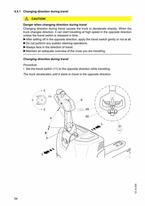
12.1
4 E
N
54
4.4.1 Changing direction during travel
CAUTION!
Danger when changing direction during travelChanging direction during travel causes the truck to decelerate sharply. When thetruck changes direction, it can start travelling at high speed in the opposite directionunless the travel switch is released in time. After setting off in the opposite direction, apply the travel switch gently or not at all.Do not perform any sudden steering operations.Always face in the direction of travel.Maintain an adequate overview of the route you are travelling.
Changing direction during travel
Procedure• Set the travel switch (11) to the opposite direction while travelling.
The truck decelerates until it starts to travel in the opposite direction.
0
B
F
B
911
3
2
50
492
3
51
12.1
4 E
N
54
4.4.1 Changing direction during travel
CAUTION!
Danger when changing direction during travelChanging direction during travel causes the truck to decelerate sharply. When thetruck changes direction, it can start travelling at high speed in the opposite directionunless the travel switch is released in time. After setting off in the opposite direction, apply the travel switch gently or not at all.Do not perform any sudden steering operations.Always face in the direction of travel.Maintain an adequate overview of the route you are travelling.
Changing direction during travel
Procedure• Set the travel switch (11) to the opposite direction while travelling.
The truck decelerates until it starts to travel in the opposite direction.
0
B
F
B
911
3
2
50
492
3
51
55
12.1
4 E
N4.5 Slow travel
CAUTION!
Risk of accident if the service brake is deactivatedParticular care and attention is required by the operator during slow travel. Theservice brake is deactivated during slow travel and is only reactivated after the "slowtravel" button is released.In hazardous situations brake by immediately releasing the "slow travel" button and
the travel switch.During slow travel you can only brake by coating braking.
Z The truck can be operated with an upright tiller (8) (e. g. in confined spaces /elevators).
Switch on the slow travel function
Procedure• Press the slow travel speed button (49).
Z The operating status can only be changed when the truck is stationary and the tillerin the travel position (F).LED (50) lit red = slow travel activated.
• Rotate the travel switch (11) in the required travel direction.
The brake is released. The truck travels at slow speed.
CAUTION!
In hazardous situations you can brake by pressing the slow travel speed button (49)again.
Switching off slow travel
Procedure• Press the slow travel speed button (49) again.
Z LED (50) lit green = slow travel deactivated.• Release the travel switch (11).
Slow travel ends and the truck can now travel again at normal speed.
4.6 Horn
Procedure• Press the horn button (51) to activate the audible warning signal.
55
12.1
4 E
N
4.5 Slow travel
CAUTION!
Risk of accident if the service brake is deactivatedParticular care and attention is required by the operator during slow travel. Theservice brake is deactivated during slow travel and is only reactivated after the "slowtravel" button is released.In hazardous situations brake by immediately releasing the "slow travel" button and
the travel switch.During slow travel you can only brake by coating braking.
Z The truck can be operated with an upright tiller (8) (e. g. in confined spaces /elevators).
Switch on the slow travel function
Procedure• Press the slow travel speed button (49).
Z The operating status can only be changed when the truck is stationary and the tillerin the travel position (F).LED (50) lit red = slow travel activated.
• Rotate the travel switch (11) in the required travel direction.
The brake is released. The truck travels at slow speed.
CAUTION!
In hazardous situations you can brake by pressing the slow travel speed button (49)again.
Switching off slow travel
Procedure• Press the slow travel speed button (49) again.
Z LED (50) lit green = slow travel deactivated.• Release the travel switch (11).
Slow travel ends and the truck can now travel again at normal speed.
4.6 Horn
Procedure• Press the horn button (51) to activate the audible warning signal.
12.1
4 E
N
56
4.7 Steering
Procedure• Move the tiller (9) to the left or right.
The truck is steered in the required direction.
4.8 Brakes
WARNING!
Accident risk while brakingThe truck’s braking response depends largely on the floor condition and the type ofsurface. The truck’s braking distance increases when the ground is wet or dirty.The operator must be aware of floor conditions and take them into account when
braking.Brake with care to prevent the load from slipping.
CAUTION!
In hazardous situations set the tiller to the brake position or press the EmergencyDisconnect switch.
The truck can brake in different ways:
– By automatic braking.– With the service brake (brake zone B).– With the plugging brake.– With the coasting brake.
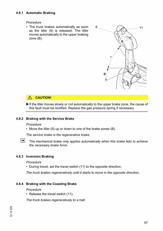
57
12.1
4 E
N4.8.1 Automatic Braking
Procedure• The truck brakes automatically as soon
as the tiller (9) is released. The tillermoves automatically to the upper brakingzone (B).
CAUTION!
If the tiller moves slowly or not automatically to the upper brake zone, the cause ofthis fault must be rectified. Replace the gas pressure spring if necessary.
4.8.2 Braking with the Service Brake
Procedure• Move the tiller (9) up or down to one of the brake zones (B).
The service brake is the regenerative brake.
Z The mechanical brake only applies automatically when this brake fails to achievethe necessary brake force.
4.8.3 Inversion Braking
Procedure• During travel, set the travel switch (11) to the opposite direction.
The truck brakes regeneratively until it starts to move in the opposite direction.
4.8.4 Braking with the Coasting Brake
Procedure• Release the travel switch (11).
The truck brakes regeneratively to a halt.
B
F
B
9 11
57
12.1
4 E
N
4.8.1 Automatic Braking
Procedure• The truck brakes automatically as soon
as the tiller (9) is released. The tillermoves automatically to the upper brakingzone (B).
CAUTION!
If the tiller moves slowly or not automatically to the upper brake zone, the cause ofthis fault must be rectified. Replace the gas pressure spring if necessary.
4.8.2 Braking with the Service Brake
Procedure• Move the tiller (9) up or down to one of the brake zones (B).
The service brake is the regenerative brake.
Z The mechanical brake only applies automatically when this brake fails to achievethe necessary brake force.
4.8.3 Inversion Braking
Procedure• During travel, set the travel switch (11) to the opposite direction.
The truck brakes regeneratively until it starts to move in the opposite direction.
4.8.4 Braking with the Coasting Brake
Procedure• Release the travel switch (11).
The truck brakes regeneratively to a halt.
B
F
B
9 11
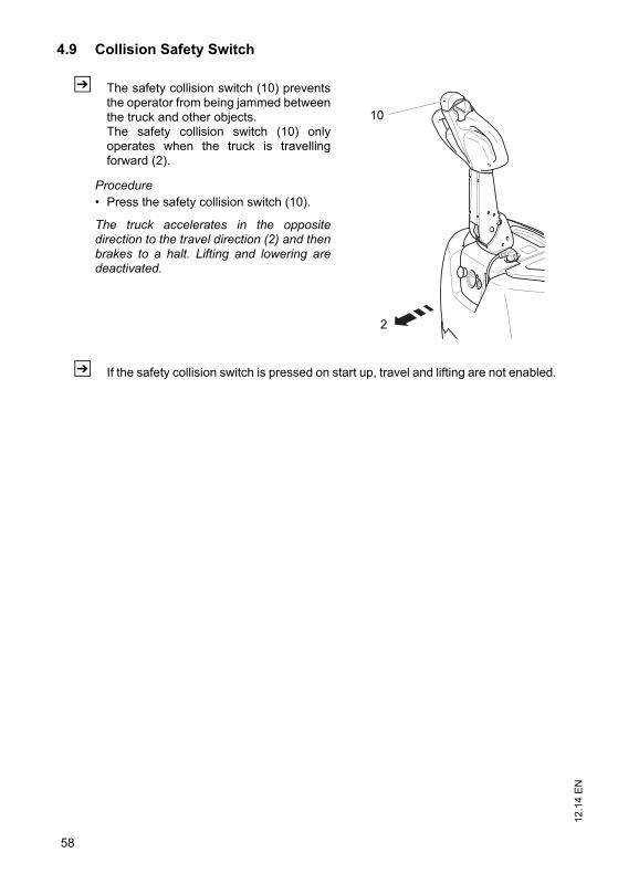
12.1
4 E
N
58
4.9 Collision Safety Switch
Z The safety collision switch (10) preventsthe operator from being jammed betweenthe truck and other objects.The safety collision switch (10) onlyoperates when the truck is travellingforward (2).
Procedure• Press the safety collision switch (10).
The truck accelerates in the oppositedirection to the travel direction (2) and thenbrakes to a halt. Lifting and lowering aredeactivated.
Z If the safety collision switch is pressed on start up, travel and lifting are not enabled.
10
2
59
12.1
4 E
N4.10 Load handler raise/lower
WARNING!
Accident risk when lifting and loweringOther people can be injured in the truck's hazardous area.The hazardous area is defined as the area in which people are at risk from themovement of the truck including the load handler, etc. This also includes areas whichcan be reached by falling loads, operating equipment, etc.Apart from the driver (in the normal operating position) there should be no otherpeople in the truck's hazardous area.Instruct other people to move out of the hazardous area of the truck. Stop working
with the truck if people do not leave the hazardous area.If people do not leave the hazardous area despite the warning, prevent the truck
from being used by unauthorised people.Only carry loads that have been secured and positioned in accordance with
regulations. Use suitable precautions to prevent parts of the load from tipping orfalling down.
Never exceed the maximum loads specified on the capacity plate.Do not stand on the load handler.Do not lift other people on the load handler.Never reach or climb into moving truck parts.Do not climb onto parts of the building or other trucks.
59
12.1
4 E
N
4.10 Load handler raise/lower
WARNING!
Accident risk when lifting and loweringOther people can be injured in the truck's hazardous area.The hazardous area is defined as the area in which people are at risk from themovement of the truck including the load handler, etc. This also includes areas whichcan be reached by falling loads, operating equipment, etc.Apart from the driver (in the normal operating position) there should be no otherpeople in the truck's hazardous area.Instruct other people to move out of the hazardous area of the truck. Stop working
with the truck if people do not leave the hazardous area.If people do not leave the hazardous area despite the warning, prevent the truck
from being used by unauthorised people.Only carry loads that have been secured and positioned in accordance with
regulations. Use suitable precautions to prevent parts of the load from tipping orfalling down.
Never exceed the maximum loads specified on the capacity plate.Do not stand on the load handler.Do not lift other people on the load handler.Never reach or climb into moving truck parts.Do not climb onto parts of the building or other trucks.
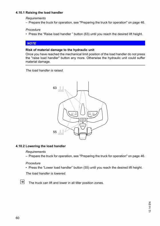
12.1
4 E
N
60
4.10.1 Raising the load handler
Requirements– Prepare the truck for operation, see "Preparing the truck for operation" on page 46.
Procedure• Press the “Raise load handler ” button (63) until you reach the desired lift height.
NOTE
Risk of material damage to the hydraulic unitOnce you have reached the mechanical limit position of the load handler do not pressthe "raise load handler" button any more. Otherwise the hydraulic unit could suffermaterial damage.
The load handler is raised.
4.10.2 Lowering the load handler
Requirements– Prepare the truck for operation, see "Preparing the truck for operation" on page 46.
Procedure• Press the “Lower load handler” button (55) until you reach the desired lift height.
The load handler is lowered.
Z The truck can lift and lower in all tiller position zones.
63
55
12.1
4 E
N
60
4.10.1 Raising the load handler
Requirements– Prepare the truck for operation, see "Preparing the truck for operation" on page 46.
Procedure• Press the “Raise load handler ” button (63) until you reach the desired lift height.
NOTE
Risk of material damage to the hydraulic unitOnce you have reached the mechanical limit position of the load handler do not pressthe "raise load handler" button any more. Otherwise the hydraulic unit could suffermaterial damage.
The load handler is raised.
4.10.2 Lowering the load handler
Requirements– Prepare the truck for operation, see "Preparing the truck for operation" on page 46.
Procedure• Press the “Lower load handler” button (55) until you reach the desired lift height.
The load handler is lowered.
Z The truck can lift and lower in all tiller position zones.
63
55
61
12.1
4 E
N4.11 Lifting, transporting and depositing loads
WARNING!
Unsecured and incorrectly positioned loads can cause accidents. Before lifting a load unit, the driver must make sure that it has been correctlypalletised and does not exceed the truck’s capacity.Instruct other people to move out of the hazardous area of the truck. Stop working
with the truck if people do not leave the hazardous area.Only carry loads that have been correctly secured and positioned. Use suitable
precautions to prevent parts of the load from tipping over or falling off the truck.Damaged loads must not be transported.Never exceed the maximum loads specified on the load diagram.Never stand underneath a raised load handler.Do not stand on the load handler.Do not lift other people on the load handler.Insert the load handler as far as possible underneath the load.
61
12.1
4 E
N
4.11 Lifting, transporting and depositing loads
WARNING!
Unsecured and incorrectly positioned loads can cause accidents. Before lifting a load unit, the driver must make sure that it has been correctlypalletised and does not exceed the truck’s capacity.Instruct other people to move out of the hazardous area of the truck. Stop working
with the truck if people do not leave the hazardous area.Only carry loads that have been correctly secured and positioned. Use suitable
precautions to prevent parts of the load from tipping over or falling off the truck.Damaged loads must not be transported.Never exceed the maximum loads specified on the load diagram.Never stand underneath a raised load handler.Do not stand on the load handler.Do not lift other people on the load handler.Insert the load handler as far as possible underneath the load.
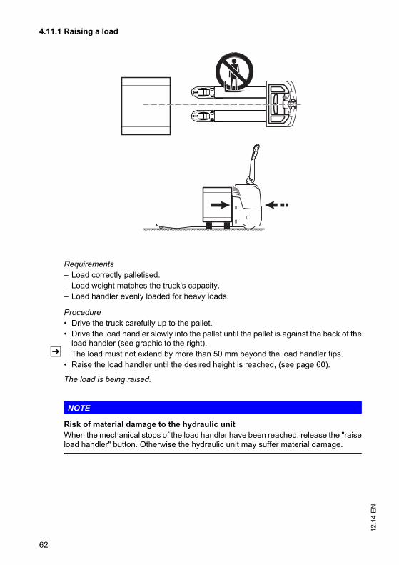
12.1
4 E
N
62
4.11.1 Raising a load
Requirements– Load correctly palletised.– Load weight matches the truck's capacity.– Load handler evenly loaded for heavy loads.
Procedure• Drive the truck carefully up to the pallet.• Drive the load handler slowly into the pallet until the pallet is against the back of the
load handler (see graphic to the right).Z The load must not extend by more than 50 mm beyond the load handler tips.
• Raise the load handler until the desired height is reached, (see page 60).
The load is being raised.
NOTE
Risk of material damage to the hydraulic unitWhen the mechanical stops of the load handler have been reached, release the "raiseload handler" button. Otherwise the hydraulic unit may suffer material damage.
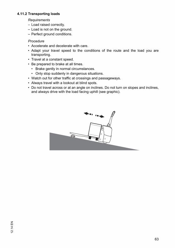
63
12.1
4 E
N4.11.2 Transporting loads
Requirements– Load raised correctly.– Load is not on the ground.– Perfect ground conditions.
Procedure• Accelerate and decelerate with care.• Adapt your travel speed to the conditions of the route and the load you are
transporting.• Travel at a constant speed.• Be prepared to brake at all times.
• Brake gently in normal circumstances.• Only stop suddenly in dangerous situations.
• Watch out for other traffic at crossings and passageways. • Always travel with a lookout at blind spots.• Do not travel across or at an angle on inclines. Do not turn on slopes and inclines,
and always drive with the load facing uphill (see graphic).
63
12.1
4 E
N
4.11.2 Transporting loads
Requirements– Load raised correctly.– Load is not on the ground.– Perfect ground conditions.
Procedure• Accelerate and decelerate with care.• Adapt your travel speed to the conditions of the route and the load you are
transporting.• Travel at a constant speed.• Be prepared to brake at all times.
• Brake gently in normal circumstances.• Only stop suddenly in dangerous situations.
• Watch out for other traffic at crossings and passageways. • Always travel with a lookout at blind spots.• Do not travel across or at an angle on inclines. Do not turn on slopes and inclines,
and always drive with the load facing uphill (see graphic).
12.1
4 E
N
64
4.11.3 Depositing a load
CAUTION!
Loads must not be set down on transport or escape routes, in front of safetyinstallations or factory equipment that must be accessible at all times.
Requirements– Storage location suitable for storing the load.
Procedure• Drive the truck carefully up to the storage location.• Lowers the load handler.
Z To avoid damaging the load and the load handler, avoid setting the load downabruptly.
• Lower the load handler so that it is clear of the load (see page 60).• Carefully drive the load handler out from beneath the pallet.
The load is deposited.
NOTE
Avoid depositing the load suddenly to avoid damaging the load, load handler and therack.
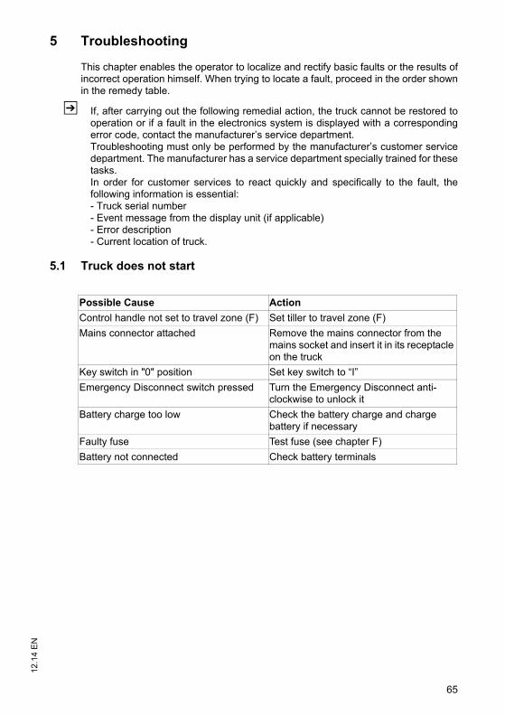
65
12.1
4 E
N5 Troubleshooting
This chapter enables the operator to localize and rectify basic faults or the results ofincorrect operation himself. When trying to locate a fault, proceed in the order shownin the remedy table.
Z If, after carrying out the following remedial action, the truck cannot be restored tooperation or if a fault in the electronics system is displayed with a correspondingerror code, contact the manufacturer’s service department.Troubleshooting must only be performed by the manufacturer’s customer servicedepartment. The manufacturer has a service department specially trained for thesetasks.In order for customer services to react quickly and specifically to the fault, thefollowing information is essential:- Truck serial number- Event message from the display unit (if applicable)- Error description- Current location of truck.
5.1 Truck does not start
Possible Cause Action
Control handle not set to travel zone (F) Set tiller to travel zone (F)
Mains connector attached Remove the mains connector from the mains socket and insert it in its receptacle on the truck
Key switch in "0" position Set key switch to “I”
Emergency Disconnect switch pressed Turn the Emergency Disconnect anti-clockwise to unlock it
Battery charge too low Check the battery charge and charge battery if necessary
Faulty fuse Test fuse (see chapter F)
Battery not connected Check battery terminals
65
12.1
4 E
N
5 Troubleshooting
This chapter enables the operator to localize and rectify basic faults or the results ofincorrect operation himself. When trying to locate a fault, proceed in the order shownin the remedy table.
Z If, after carrying out the following remedial action, the truck cannot be restored tooperation or if a fault in the electronics system is displayed with a correspondingerror code, contact the manufacturer’s service department.Troubleshooting must only be performed by the manufacturer’s customer servicedepartment. The manufacturer has a service department specially trained for thesetasks.In order for customer services to react quickly and specifically to the fault, thefollowing information is essential:- Truck serial number- Event message from the display unit (if applicable)- Error description- Current location of truck.
5.1 Truck does not start
Possible Cause Action
Control handle not set to travel zone (F) Set tiller to travel zone (F)
Mains connector attached Remove the mains connector from the mains socket and insert it in its receptacle on the truck
Key switch in "0" position Set key switch to “I”
Emergency Disconnect switch pressed Turn the Emergency Disconnect anti-clockwise to unlock it
Battery charge too low Check the battery charge and charge battery if necessary
Faulty fuse Test fuse (see chapter F)
Battery not connected Check battery terminals
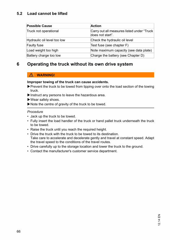
12.1
4 E
N
66
5.2 Load cannot be lifted
6 Operating the truck without its own drive system
WARNING!
Improper towing of the truck can cause accidents.Prevent the truck to be towed from tipping over onto the load section of the towing
truck.Instruct any persons to leave the hazardous area.Wear safety shoes.Note the centre of gravity of the truck to be towed.
Procedure• Jack up the truck to be towed.• Fully insert the load handler of the truck or hand pallet truck underneath the truck
to be towed.• Raise the truck until you reach the required height.• Drive the truck with the truck to be towed to its destination.
Take care to accelerate and decelerate gently and travel at constant speed. Adaptthe travel speed to the conditions of the travel routes.
• Drive carefully up to the storage location and lower the truck to the ground.• Contact the manufacturer's customer service department.
Possible Cause Action
Truck not operational Carry out all measures listed under “Truck does not start”.
Hydraulic oil level too low Check the hydraulic oil level
Faulty fuse Test fuse (see chapter F)
Load weight too high Note maximum capacity (see data plate)
Battery charge too low Charge the battery (see Chapter D)
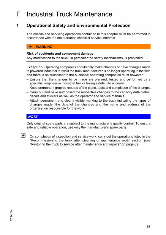
67
12.1
4 E
N
F Industrial Truck Maintenance
1 Operational Safety and Environmental Protection
The checks and servicing operations contained in this chapter must be performed inaccordance with the maintenance checklist service intervals.
WARNING!
Risk of accidents and component damageAny modification to the truck, in particular the safety mechanisms, is prohibited.
Exception: Operating companies should only make changes or have changes madeto powered industrial trucks if the truck manufacturer is no longer operating in the fieldand there is no successor to the business; operating companies must however:– Ensure that the changes to be made are planned, tested and performed by a
specialist engineer in industrial trucks taking safety into account.– Keep permanent graphic records of the plans, tests and completion of the changes– Carry out and have authorised the respective changes to the capacity data plates,
decals and stickers as well as the operator and service manuals.– Attach permanent and clearly visible marking to the truck indicating the types of
changes made, the date of the changes and the name and address of theorganisation responsible for the work.
NOTE
Only original spare parts are subject to the manufacturer's quality control. To ensuresafe and reliable operation, use only the manufacturer's spare parts.
Z On completion of inspection and service work, carry out the operations listed in the“Recommissioning the truck after cleaning or maintenance work” section (see"Restoring the truck to service after maintenance and repairs" on page 82).
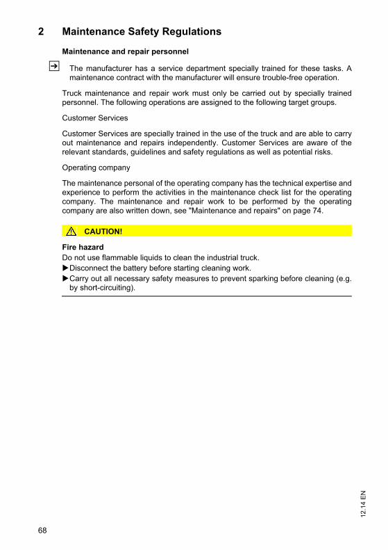
12.1
4 E
N
68
2 Maintenance Safety Regulations
Maintenance and repair personnel
Z The manufacturer has a service department specially trained for these tasks. Amaintenance contract with the manufacturer will ensure trouble-free operation.
Truck maintenance and repair work must only be carried out by specially trainedpersonnel. The following operations are assigned to the following target groups.
Customer Services
Customer Services are specially trained in the use of the truck and are able to carryout maintenance and repairs independently. Customer Services are aware of therelevant standards, guidelines and safety regulations as well as potential risks.
Operating company
The maintenance personal of the operating company has the technical expertise andexperience to perform the activities in the maintenance check list for the operatingcompany. The maintenance and repair work to be performed by the operatingcompany are also written down, see "Maintenance and repairs" on page 74.
CAUTION!
Fire hazardDo not use flammable liquids to clean the industrial truck.Disconnect the battery before starting cleaning work.Carry out all necessary safety measures to prevent sparking before cleaning (e.g.
by short-circuiting).
69
12.1
4 E
N2.1 Working on the electrical system
WARNING!
Electrical current can cause accidentsMake sure the electrical system is voltage-free before starting work on it. Thecapacitors in the controller must be completely discharged. The capacitors arecompletely discharged after approximately 10 minutes. Before starting maintenanceon the electrical system:Only suitably trained electricians may operate on the truck's electrical system.Before working on the electrical system, take all precautionary measures to avoid
electric shocks.Park the truck securely (see "Parking the truck securely" on page 48).Remove the battery, see "Battery removal and installation" on page 37.Remove any rings, metal wristbands etc.
2.2 Consumables and used parts
CAUTION!
Consumables and used parts are an environmental hazardUsed parts and consumables must be disposed of in accordance with the applicableenvironmental-protection regulations. Oil changes should be carried out by themanufacturer's customer service department, whose staff are specially trained forthis task.Note the safety regulations when handling these materials.
2.3 Wheels
WARNING!
The use of wheels that do not comply with the manufacturer's specificationscan result in accidentsThe quality of wheels affects the stability and driving characteristics of the truck. Uneven wear affects the truck's stability and increases the stopping distance. After replacing wheels, make sure the truck is not skewed.Always replace wheels in pairs, i.e. the left- and right-hand wheels at the same
time.
Z When replacing wheels fitted at the factory, only use the manufacturer’s originalspare parts. Otherwise the manufacturer's specification will not be adhered to.
69
12.1
4 E
N
2.1 Working on the electrical system
WARNING!
Electrical current can cause accidentsMake sure the electrical system is voltage-free before starting work on it. Thecapacitors in the controller must be completely discharged. The capacitors arecompletely discharged after approximately 10 minutes. Before starting maintenanceon the electrical system:Only suitably trained electricians may operate on the truck's electrical system.Before working on the electrical system, take all precautionary measures to avoid
electric shocks.Park the truck securely (see "Parking the truck securely" on page 48).Remove the battery, see "Battery removal and installation" on page 37.Remove any rings, metal wristbands etc.
2.2 Consumables and used parts
CAUTION!
Consumables and used parts are an environmental hazardUsed parts and consumables must be disposed of in accordance with the applicableenvironmental-protection regulations. Oil changes should be carried out by themanufacturer's customer service department, whose staff are specially trained forthis task.Note the safety regulations when handling these materials.
2.3 Wheels
WARNING!
The use of wheels that do not comply with the manufacturer's specificationscan result in accidentsThe quality of wheels affects the stability and driving characteristics of the truck. Uneven wear affects the truck's stability and increases the stopping distance. After replacing wheels, make sure the truck is not skewed.Always replace wheels in pairs, i.e. the left- and right-hand wheels at the same
time.
Z When replacing wheels fitted at the factory, only use the manufacturer’s originalspare parts. Otherwise the manufacturer's specification will not be adhered to.
12.1
4 E
N
70
2.4 Hydraulic system
NOTE
Testing and replacing hydraulic hosesHydraulic hoses can become brittle through age and must be checked at regularintervals. The application conditions of the industrial truck have a considerable impacton the ageing of the hydraulic hoses.Check the hydraulic hoses at least annually and replace if necessary.If the operating conditions become more arduous the inspection intervals must be
reduced accordingly.In normal operating conditions a precautionary replacement of the hydraulic hoses
is recommended after 6. The owner must carry out a risk assessment to ensuresafe, prolonged use. The resulting protection measures must be observed and theinspection interval reduced accordingly.
WARNING!
Leaky hydraulic systems can result in accidentsHydraulic oil can escape from leaky and faulty hydraulic systems.Report any defects immediately to your supervisor.Mark defective truck and take out of service.Do not return the industrial truck to service until you have identified and rectified the
fault.Remove any spilled hydraulic immediately with an appropriate bonding agent.The bonding agent / consumable mixture must be disposed of in accordance with
regulations.
WARNING!
Faulty hydraulic hoses can result in injury and infectionPressurised hydraulic oil can escape from fine holes or hairline cracks in the hydraulichoses. Brittle hydraulic hoses can burst during operation. People standing near thetruck can be injured by the hydraulic oil.Call for a doctor immediately in the event of an injury.Do not touch pressurised hydraulic hoses. Report any defects immediately to your supervisor.Mark defective truck and take it out of service.Do not return the industrial truck to service until you have identified and rectified the
fault.
71
12.1
4 E
N3 Lubricants and Lubrication Schedule
3.1 Handling consumables safely
Handling consumables
Consumables must always be handled correctly. Follow the manufacturer’sinstructions.
WARNING!
Improper handling is hazardous to health, life and the environmentConsumables can be flammable.Keep consumables away from hot components and naked flames.Always keep consumables in prescribed containers.Always fill consumables in clean containers.Do not mix up different grades of consumable. The only exception to this is when
mixing is expressly stipulated in the operating instructions.
CAUTION!
Spilled consumables can cause slipping and endanger the environmentRisk of slipping from spilled consumables. The risk is greater when combined withwater.Do not spill consumables.Spilled consumables must be removed immediately with an appropriate bonding
agent.The bonding agent / consumable mixture must be disposed of in accordance with
regulations.
71
12.1
4 E
N
3 Lubricants and Lubrication Schedule
3.1 Handling consumables safely
Handling consumables
Consumables must always be handled correctly. Follow the manufacturer’sinstructions.
WARNING!
Improper handling is hazardous to health, life and the environmentConsumables can be flammable.Keep consumables away from hot components and naked flames.Always keep consumables in prescribed containers.Always fill consumables in clean containers.Do not mix up different grades of consumable. The only exception to this is when
mixing is expressly stipulated in the operating instructions.
CAUTION!
Spilled consumables can cause slipping and endanger the environmentRisk of slipping from spilled consumables. The risk is greater when combined withwater.Do not spill consumables.Spilled consumables must be removed immediately with an appropriate bonding
agent.The bonding agent / consumable mixture must be disposed of in accordance with
regulations.
12.1
4 E
N
72
WARNING!
Improper handling of oils can be hazardousOils (chain spray / hydraulic oil) are flammable and poisonous.Dispose of used oils in accordance with regulations. Store used oil safely until it can
be disposed of in accordance with regulations.Do not spill oil.Spilled oils must be removed immediately with an appropriate bonding agent.The mixture consisting of the bonding agent and oil must be disposed of in
accordance with regulations.Observe national regulations when handling oils.Wear safety gloves when handling oils.Prevent oil from coming into contact with hot motor parts.Do not smoke when handling oil.Avoid contact and digestion. If you swallow oil do not induce vomiting but seek
medical assistance immediately.Seek fresh air after breathing in oil fumes or vapours.If oil has come into contact with your skin, rinse your skin with water.If oil has come into contact with your eyes, rinse them with water and seek medical
assistance immediately.Replace oil-soaked clothing and shoes immediately.
CAUTION!
Consumables and used parts are an environmental hazardUsed parts and consumables must be disposed of in accordance with the applicableenvironmental-protection regulations. Oil changes should be carried out by themanufacturer's customer service department, whose staff are specially trained forthis task.Note the safety regulations when handling these materials.
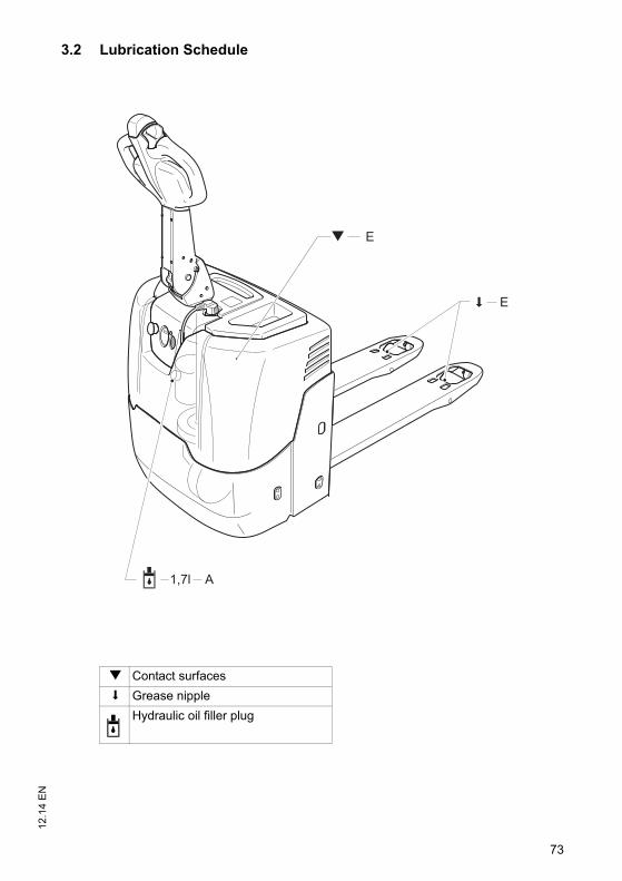
73
12.1
4 E
N3.2 Lubrication Schedule
E
A1,7l
E
g Contact surfaces
s Grease nipple
Hydraulic oil filler plug
73
12.1
4 E
N
3.2 Lubrication Schedule
E
A1,7l
E
g Contact surfaces
s Grease nipple
Hydraulic oil filler plug
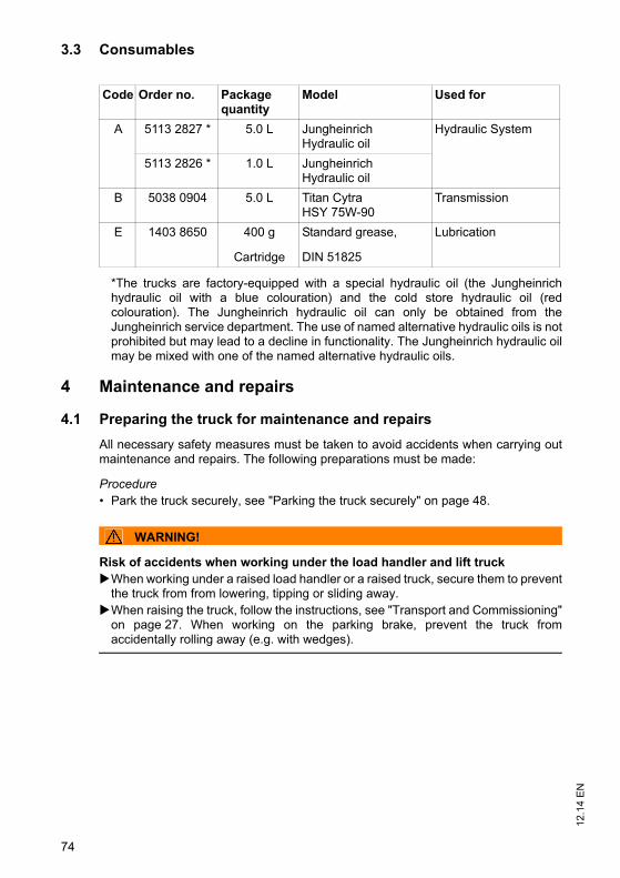
12.1
4 E
N
74
3.3 Consumables
*The trucks are factory-equipped with a special hydraulic oil (the Jungheinrichhydraulic oil with a blue colouration) and the cold store hydraulic oil (redcolouration). The Jungheinrich hydraulic oil can only be obtained from theJungheinrich service department. The use of named alternative hydraulic oils is notprohibited but may lead to a decline in functionality. The Jungheinrich hydraulic oilmay be mixed with one of the named alternative hydraulic oils.
4 Maintenance and repairs
4.1 Preparing the truck for maintenance and repairs
All necessary safety measures must be taken to avoid accidents when carrying outmaintenance and repairs. The following preparations must be made:
Procedure• Park the truck securely, see "Parking the truck securely" on page 48.
WARNING!
Risk of accidents when working under the load handler and lift truckWhen working under a raised load handler or a raised truck, secure them to prevent
the truck from from lowering, tipping or sliding away.When raising the truck, follow the instructions, see "Transport and Commissioning"
on page 27. When working on the parking brake, prevent the truck fromaccidentally rolling away (e.g. with wedges).
Code Order no. Package quantity
Model Used for
A 5113 2827 * 5.0 L JungheinrichHydraulic oil
Hydraulic System
5113 2826 * 1.0 L JungheinrichHydraulic oil
B 5038 0904 5.0 L Titan CytraHSY 75W-90
Transmission
E 1403 8650 400 g
Cartridge
Standard grease,
DIN 51825
Lubrication
75
12.1
4 E
N4.2 Lifting and jacking up the truck safely
WARNING!
A truck tipover can cause accidentsIn order to raise the truck, use only suitable lifting gear at the points specially providedfor this purpose. Note the weight of the truck on the data plate.Always use a jack with a minimum capacity of 5000 kg kg.Raise the unladen truck on a level surface.When raising the truck, take appropriate measures to prevent it from slipping or
tipping over (e.g. wedges, wooden blocks).
Raising and jacking up the truck securely
Requirements– Prepare the truck for maintenance and repairs (see "Preparing the truck for
maintenance and repairs" on page 74).
Tools and Material Required– Jack– Hard wooden blocks
Procedure• Place the jack against the contact point.
Z Jack contact point, see "Identification Points and Data Plates" on page 24.• Raise the truck.• Support the truck with hard wooden blocks.• Remove the jack.
The truck is now securely raised and jacked up.
75
12.1
4 E
N
4.2 Lifting and jacking up the truck safely
WARNING!
A truck tipover can cause accidentsIn order to raise the truck, use only suitable lifting gear at the points specially providedfor this purpose. Note the weight of the truck on the data plate.Always use a jack with a minimum capacity of 5000 kg kg.Raise the unladen truck on a level surface.When raising the truck, take appropriate measures to prevent it from slipping or
tipping over (e.g. wedges, wooden blocks).
Raising and jacking up the truck securely
Requirements– Prepare the truck for maintenance and repairs (see "Preparing the truck for
maintenance and repairs" on page 74).
Tools and Material Required– Jack– Hard wooden blocks
Procedure• Place the jack against the contact point.
Z Jack contact point, see "Identification Points and Data Plates" on page 24.• Raise the truck.• Support the truck with hard wooden blocks.• Remove the jack.
The truck is now securely raised and jacked up.
12.1
4 E
N
76
4.3 Cleaning
4.3.1 Cleaning the truck
CAUTION!
Fire hazardDo not use flammable liquids to clean the industrial truck.Before starting cleaning work disconnect the truck from the mains if applicable and
disconnect the battery, see "Battery Replacement" on page 37.Carry out all necessary safety measures to prevent sparking before cleaning (e.g.
by short-circuiting).
CAUTION!
Risk of component damage when cleaning the truckCleaning with a pressure washer can result in malfunctions due to humidity.Cover all electronic system assemblies (controllers, sensors, motors etc.) before
cleaning the truck with a pressure washer.Do not hold the jet of the pressure washer by the marked points to avoid damaging
them (see "Identification Points and Data Plates" on page 24).Do not clean the truck with pressurised water.
77
12.1
4 E
N
Cleaning the truck
Requirements– Prepare the truck for maintenance and repairs (see "Preparing the truck for
maintenance and repairs" on page 74).
Tools and Material Required– Water-based solvents– Sponge or cloth
Procedure• Clean the surface of the truck with water-based solvents and water. Use a sponge
or cloth to clean.• In particular, clean the following areas:
• Window(s)• Oil filler ports and their surroundings• Grease nipples (before lubrication)
• Dry the truck after cleaning, e.g. with compressed air or a dry cloth.• Carry out all the tasks in the section "Recommissioning the truck after cleaning or
maintenance work" (see "Restoring the truck to service after maintenance andrepairs" on page 82).
The truck is now clean.
4.3.2 Cleaning the electrical system assemblies
CAUTION!
Risk of electrical system damageCleaning the assemblies (controllers, sensors, motors etc.) of the electronic systemwith water can damage the electrical system.Do not clean the electrical system with water.Clean the electrical system with weak suction or compressed air (use a compressor
with a water trap) and not a conductive, anti-static brush.
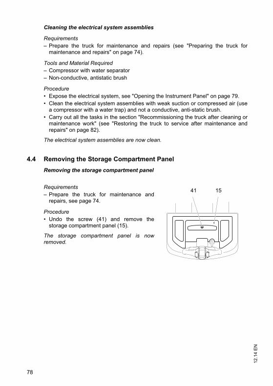
12.1
4 E
N
78
Cleaning the electrical system assemblies
Requirements– Prepare the truck for maintenance and repairs (see "Preparing the truck for
maintenance and repairs" on page 74).
Tools and Material Required– Compressor with water separator– Non-conductive, antistatic brush
Procedure• Expose the electrical system, see "Opening the Instrument Panel" on page 79.• Clean the electrical system assemblies with weak suction or compressed air (use
a compressor with a water trap) and not a conductive, anti-static brush.• Carry out all the tasks in the section "Recommissioning the truck after cleaning or
maintenance work" (see "Restoring the truck to service after maintenance andrepairs" on page 82).
The electrical system assemblies are now clean.
4.4 Removing the Storage Compartment Panel
Removing the storage compartment panel
Requirements– Prepare the truck for maintenance and
repairs, see page 74.
Procedure• Undo the screw (41) and remove the
storage compartment panel (15).
The storage compartment panel is nowremoved.
41 15
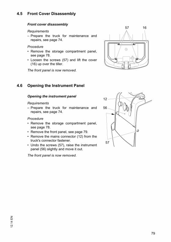
79
12.1
4 E
N4.5 Front Cover Disassembly
Front cover disassembly
Requirements– Prepare the truck for maintenance and
repairs, see page 74.
Procedure• Remove the storage compartment panel,
see page 78.• Loosen the screws (57) and lift the cover
(16) up over the tiller.
The front panel is now removed.
4.6 Opening the Instrument Panel
Opening the instrument panel
Requirements– Prepare the truck for maintenance and
repairs, see page 74.
Procedure• Remove the storage compartment panel,
see page 78.• Remove the front panel, see page 79.• Remove the mains connector (12) from the
truck's connector fastener.• Undo the screws (57), raise the instrument
panel (56) slightly and move it out.
The front panel is now removed.
57 16
12
56
57
79
12.1
4 E
N
4.5 Front Cover Disassembly
Front cover disassembly
Requirements– Prepare the truck for maintenance and
repairs, see page 74.
Procedure• Remove the storage compartment panel,
see page 78.• Loosen the screws (57) and lift the cover
(16) up over the tiller.
The front panel is now removed.
4.6 Opening the Instrument Panel
Opening the instrument panel
Requirements– Prepare the truck for maintenance and
repairs, see page 74.
Procedure• Remove the storage compartment panel,
see page 78.• Remove the front panel, see page 79.• Remove the mains connector (12) from the
truck's connector fastener.• Undo the screws (57), raise the instrument
panel (56) slightly and move it out.
The front panel is now removed.
57 16
12
56
57
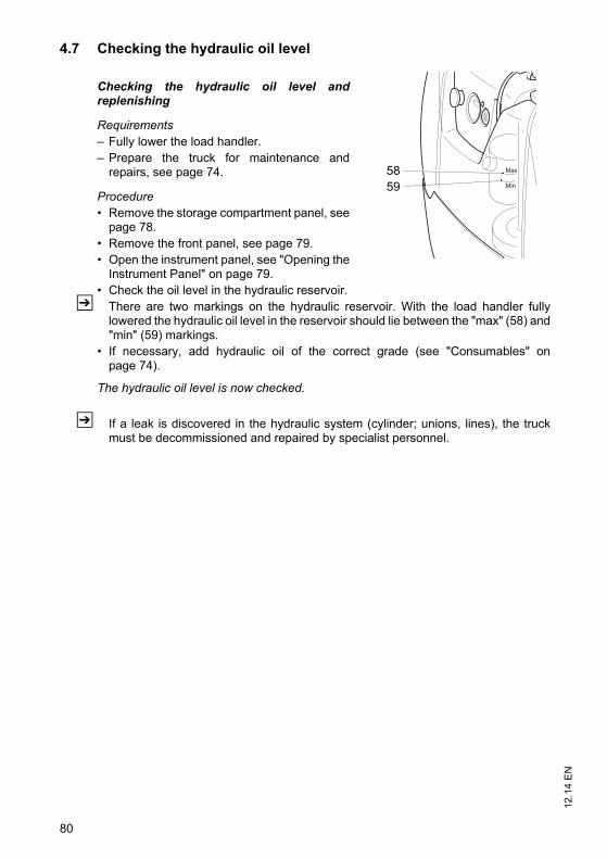
12.1
4 E
N
80
4.7 Checking the hydraulic oil level
Checking the hydraulic oil level andreplenishing
Requirements– Fully lower the load handler.– Prepare the truck for maintenance and
repairs, see page 74.
Procedure• Remove the storage compartment panel, see
page 78.• Remove the front panel, see page 79.• Open the instrument panel, see "Opening the
Instrument Panel" on page 79.• Check the oil level in the hydraulic reservoir.
Z There are two markings on the hydraulic reservoir. With the load handler fullylowered the hydraulic oil level in the reservoir should lie between the "max" (58) and"min" (59) markings.
• If necessary, add hydraulic oil of the correct grade (see "Consumables" onpage 74).
The hydraulic oil level is now checked.
Z If a leak is discovered in the hydraulic system (cylinder; unions, lines), the truckmust be decommissioned and repaired by specialist personnel.
Max
Min
5859
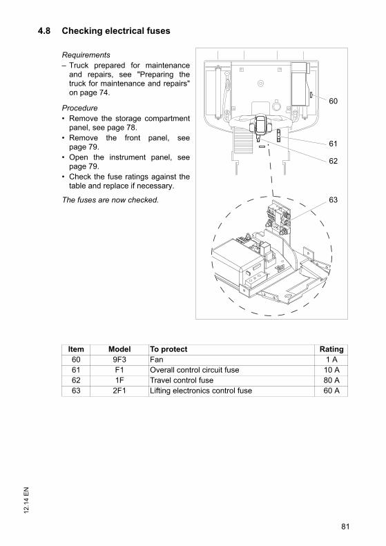
81
12.1
4 E
N4.8 Checking electrical fuses
Requirements– Truck prepared for maintenance
and repairs, see "Preparing thetruck for maintenance and repairs"on page 74.
Procedure• Remove the storage compartment
panel, see page 78.• Remove the front panel, see
page 79.• Open the instrument panel, see
page 79.• Check the fuse ratings against the
table and replace if necessary.
The fuses are now checked.
60
61
62
63
Item Model To protect Rating60 9F3 Fan 1 A61 F1 Overall control circuit fuse 10 A62 1F Travel control fuse 80 A63 2F1 Lifting electronics control fuse 60 A
81
12.1
4 E
N
4.8 Checking electrical fuses
Requirements– Truck prepared for maintenance
and repairs, see "Preparing thetruck for maintenance and repairs"on page 74.
Procedure• Remove the storage compartment
panel, see page 78.• Remove the front panel, see
page 79.• Open the instrument panel, see
page 79.• Check the fuse ratings against the
table and replace if necessary.
The fuses are now checked.
60
61
62
63
Item Model To protect Rating60 9F3 Fan 1 A61 F1 Overall control circuit fuse 10 A62 1F Travel control fuse 80 A63 2F1 Lifting electronics control fuse 60 A
12.1
4 E
N
82
4.9 Restoring the truck to service after maintenance and repairs
Procedure• Thoroughly clean the truck, see "Cleaning" on page 76.• Lubricate the truck according to the lubrication schedule, see "Lubrication
Schedule" on page 73.• Clean the battery, grease the terminals and connect the battery.• Charge the battery, see "Charging the battery" on page 34• Replace transmission oil. Condensation water could have formed.• Replace hydraulic oil. Condensation water could have formed.
Z The manufacturer's customer service department is specially trained to carry outthese operations.
• Start up the truck, see page 45.
WARNING!
Faulty brakes can cause accidentsAs soon as the truck has been started, test the brakes several times.Report any defects immediately to your supervisor.Tag out and decommission the faulty industrial truck.Only return the truck to service when you have identified and rectified the fault.
Z If there are switching problems in the electrical system, apply contact spray to theexposed contacts and remove any oxide layers on the contacts of the controls byapplying them repeatedly.
83
12.1
4 E
N5 Decommissioning the Industrial Truck
If the truck is to be out of service for more than a month, it must be stored in a frost-free and dry room. All necessary measures must be taken before, during and afterdecommissioning as described hereafter.
When the truck is out of service it must be jacked up so that all the wheels are clearof the ground. This is the only way of ensuring that the wheels and wheel bearingsare not damaged.
If the truck is to be out of service for more than 6 months, agree further measures withthe manufacturer's customer service department.
5.1 Prior to decommissioning
Procedure• Thoroughly clean the truck, see "Cleaning" on page 76.• Prevent the truck from rolling away accidentally.• Check the hydraulic oil level and replenish if necessary, see page 80.• Apply a thin layer of oil or grease to any non-painted mechanical components.• Lubricate the truck according to the lubrication schedule, see page 73.• Charge the battery, see page 34.• Disconnect the battery, clean it and grease the terminals.
Z In addition, follow the battery manufacturer’s instructions.
5.2 Action to be Taken During Decommissioning
NOTE
Full discharge can damage the batterySelf-discharge can cause the battery to fully discharge. Full discharge shortens theuseful life of the battery. Charge the battery at least every 2 months.
Z Charge the battery, see page 34
83
12.1
4 E
N
5 Decommissioning the Industrial Truck
If the truck is to be out of service for more than a month, it must be stored in a frost-free and dry room. All necessary measures must be taken before, during and afterdecommissioning as described hereafter.
When the truck is out of service it must be jacked up so that all the wheels are clearof the ground. This is the only way of ensuring that the wheels and wheel bearingsare not damaged.
If the truck is to be out of service for more than 6 months, agree further measures withthe manufacturer's customer service department.
5.1 Prior to decommissioning
Procedure• Thoroughly clean the truck, see "Cleaning" on page 76.• Prevent the truck from rolling away accidentally.• Check the hydraulic oil level and replenish if necessary, see page 80.• Apply a thin layer of oil or grease to any non-painted mechanical components.• Lubricate the truck according to the lubrication schedule, see page 73.• Charge the battery, see page 34.• Disconnect the battery, clean it and grease the terminals.
Z In addition, follow the battery manufacturer’s instructions.
5.2 Action to be Taken During Decommissioning
NOTE
Full discharge can damage the batterySelf-discharge can cause the battery to fully discharge. Full discharge shortens theuseful life of the battery. Charge the battery at least every 2 months.
Z Charge the battery, see page 34
12.1
4 E
N
84
5.3 Restoring the truck to service after decommissioning
Procedure• Thoroughly clean the truck, see "Cleaning" on page 76.• Lubricate the truck according to the lubrication schedule, see page 73.• Clean the battery, grease the terminals and connect the battery.• Charge the battery, see page 34.• Replace transmission oil. Condensation water could have formed.• Replace hydraulic oil. Condensation water could have formed.
Z The manufacturer's customer service department is specially trained to carry outthese operations.
• Start up the truck, see "Preparing the Truck for Operation" on page 45.
WARNING!
Faulty brakes can cause accidentsAs soon as the truck has been started, test the brakes several times.Report any defects immediately to your supervisor.Tag out and decommission the faulty industrial truck.Only return the truck to service when you have identified and rectified the fault.
Z If there are switching problems in the electrical system, apply contact spray to theexposed contacts and remove any oxide layers on the contacts of the controls byapplying them repeatedly.
85
12.1
4 E
N6 Safety tests to be performed at intervals and after unusual
incidents
The truck must be inspected at least annually (refer to national regulations) or afterany unusual event by a qualified inspector. The manufacturer offers a safetyinspection service which is performed by personnel specifically trained for thispurpose.
A complete test must be carried out on the technical condition of the truck with regardto safety. The truck must also be examined thoroughly for damage.
The operating company is responsible for ensuring that faults are rectifiedimmediately.
7 Final de-commissioning, disposal
Z Final de-commissioning or disposal of the truck in must be performed inaccordance with the regulations of the country of use. In particular, regulationsgoverning the disposal of batteries, consumables and electronic and electricalsystems must be observed.
The truck must only be disassembled by trained personnel in accordance with theprocedures as specified by the manufacturer.
8 Human vibration measurement
Z Vibrations that affect the operator over the course of the day are known as humanvibrations. Excessive human vibrations will cause the operator long term healthproblems. The European "2002/44/EC/Vibration" operator directive has thereforebeen established to protect operators. To help operators to assess the applicationsituation, the manufacturer offers a service of measuring these human vibrations.
85
12.1
4 E
N
6 Safety tests to be performed at intervals and after unusual incidents
The truck must be inspected at least annually (refer to national regulations) or afterany unusual event by a qualified inspector. The manufacturer offers a safetyinspection service which is performed by personnel specifically trained for thispurpose.
A complete test must be carried out on the technical condition of the truck with regardto safety. The truck must also be examined thoroughly for damage.
The operating company is responsible for ensuring that faults are rectifiedimmediately.
7 Final de-commissioning, disposal
Z Final de-commissioning or disposal of the truck in must be performed inaccordance with the regulations of the country of use. In particular, regulationsgoverning the disposal of batteries, consumables and electronic and electricalsystems must be observed.
The truck must only be disassembled by trained personnel in accordance with theprocedures as specified by the manufacturer.
8 Human vibration measurement
Z Vibrations that affect the operator over the course of the day are known as humanvibrations. Excessive human vibrations will cause the operator long term healthproblems. The European "2002/44/EC/Vibration" operator directive has thereforebeen established to protect operators. To help operators to assess the applicationsituation, the manufacturer offers a service of measuring these human vibrations.
12.1
4 E
N
86
9 Servicing and Inspection
WARNING!
Lack of maintenance can result in accidentsFailure to perform regular servicing can lead to truck failure and poses a potentialhazard to personnel and equipment.Thorough and expert servicing is one of the most important requirements for the
safe operation of the industrial truck.
The application conditions of an industrial truck have a considerable impact oncomponent wear. The following service intervals are based on single-shift operationunder normal operating conditions. They must be reduced accordingly if theequipment is to be used in conditions of extreme dust, temperature fluctuations ormultiple shifts.
NOTE
To prevent damage due to wear, the manufacturer recommends an on-siteapplication analysis to agree on appropriate service intervals.
The following maintenance checklist lists the activities to be performed and therespective intervals to be observed. Maintenance intervals are defined as:
Z "W" maintenance interval operations should be performed by the operatingcompany.
During the run-in period,after approx. 100 service hours, the owner must check thewheel nuts/bolts and re-tighten if necessary.
W = Every 50 service hours, at least weekly
A = Every 500 service hours
B = Every 1000 service hours, or at least annually
C = Every 2000 service hours, or at least annually
t = Standard maintenance interval
k =Cold store maintenance interval (in addition to standard maintenance interval)
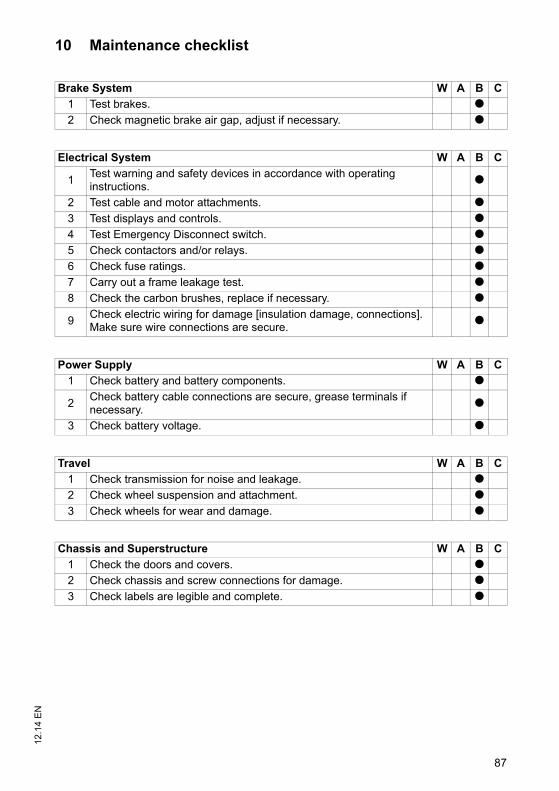
87
12.1
4 E
N10 Maintenance checklist
Brake System W A B C
1 Test brakes. t2 Check magnetic brake air gap, adjust if necessary. t
Electrical System W A B C
1Test warning and safety devices in accordance with operating instructions.
t
2 Test cable and motor attachments. t3 Test displays and controls. t4 Test Emergency Disconnect switch. t5 Check contactors and/or relays. t6 Check fuse ratings. t7 Carry out a frame leakage test. t8 Check the carbon brushes, replace if necessary. t
9Check electric wiring for damage [insulation damage, connections]. Make sure wire connections are secure.
t
Power Supply W A B C
1 Check battery and battery components. t
2Check battery cable connections are secure, grease terminals if necessary.
t
3 Check battery voltage. t
Travel W A B C
1 Check transmission for noise and leakage. t2 Check wheel suspension and attachment. t3 Check wheels for wear and damage. t
Chassis and Superstructure W A B C
1 Check the doors and covers. t2 Check chassis and screw connections for damage. t3 Check labels are legible and complete. t
87
12.1
4 E
N
10 Maintenance checklist
Brake System W A B C
1 Test brakes. t2 Check magnetic brake air gap, adjust if necessary. t
Electrical System W A B C
1Test warning and safety devices in accordance with operating instructions.
t
2 Test cable and motor attachments. t3 Test displays and controls. t4 Test Emergency Disconnect switch. t5 Check contactors and/or relays. t6 Check fuse ratings. t7 Carry out a frame leakage test. t8 Check the carbon brushes, replace if necessary. t
9Check electric wiring for damage [insulation damage, connections]. Make sure wire connections are secure.
t
Power Supply W A B C
1 Check battery and battery components. t
2Check battery cable connections are secure, grease terminals if necessary.
t
3 Check battery voltage. t
Travel W A B C
1 Check transmission for noise and leakage. t2 Check wheel suspension and attachment. t3 Check wheels for wear and damage. t
Chassis and Superstructure W A B C
1 Check the doors and covers. t2 Check chassis and screw connections for damage. t3 Check labels are legible and complete. t
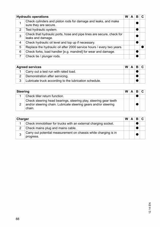
12.1
4 E
N
88
Hydraulic operations W A B C
1Check cylinders and piston rods for damage and leaks, and make sure they are secure.
t
2 Test hydraulic system. t
3Check that hydraulic ports, hose and pipe lines are secure, check for leaks and damage.
t
4 Check hydraulic oil level and top up if necessary. t5 Replace the hydraulic oil after 2000 service hours / every two years. t6 Check forks, load handler [e.g. mandrel] for wear and damage. t7 Check tie / plunger rods. t
Agreed services W A B C
1 Carry out a test run with rated load. t2 Demonstration after servicing. t3 Lubricate truck according to the lubrication schedule. t
Steering W A B C
1 Check tiller return function. t
2Check steering head bearings, steering play, steering gear teeth and/or steering chain. Lubricate steering gears and/or steering chain.
t
Charger W A B C
1 Check immobiliser for trucks with an external charging socket. t2 Check mains plug and mains cable. t
3Carry out potential measurement on chassis while charging is in progress.
t
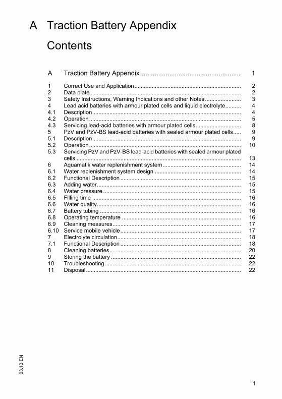
1
03.1
3 E
N
A Traction Battery Appendix
Contents
A Traction Battery Appendix....................................................... 1
1 Correct Use and Application.................................................................... 22 Data plate ................................................................................................ 23 Safety Instructions, Warning Indications and other Notes....................... 34 Lead acid batteries with armour plated cells and liquid electrolyte.......... 44.1 Description............................................................................................... 44.2 Operation................................................................................................. 54.3 Servicing lead-acid batteries with armour plated cells............................. 85 PzV and PzV-BS lead-acid batteries with sealed armour plated cells..... 95.1 Description............................................................................................... 95.2 Operation................................................................................................. 105.3 Servicing PzV and PzV-BS lead-acid batteries with sealed armour plated
cells ......................................................................................................... 136 Aquamatik water replenishment system.................................................. 146.1 Water replenishment system design ....................................................... 146.2 Functional Description ............................................................................. 156.3 Adding water............................................................................................ 156.4 Water pressure ........................................................................................ 156.5 Filling time ............................................................................................... 166.6 Water quality............................................................................................ 166.7 Battery tubing .......................................................................................... 166.8 Operating temperature ............................................................................ 166.9 Cleaning measures.................................................................................. 176.10 Service mobile vehicle............................................................................. 177 Electrolyte circulation............................................................................... 187.1 Functional Description ............................................................................. 188 Cleaning batteries.................................................................................... 209 Storing the battery ................................................................................... 2210 Troubleshooting....................................................................................... 2211 Disposal................................................................................................... 22
03.1
3 E
N
2
1 Correct Use and Application
Failure to observe the operating instructions, carrying out repairs with non-originalspare parts, tampering with the battery or using electrolyte additives will invalidate thewarranty.
Observe the instructions for maintaining the safety rating during operation forbatteries in accordance with Ex I and Ex II (see relevant certification).
2 Data plate
1,2
4
8
10
11
6
3
5
9
7
12 13
14
15
1 Battery name2 Battery type3 Production week/year manf.4 Serial number5 Supplier number6 Rated voltage7 Rated capacity9 Battery weight in kg8 Number of cells15 Electrolyte volume in litres10 Battery number11 Manufacturer13 Manufacturer's logo12 CE mark only for batteries beyond 75 volts14 Safety instructions and warning information
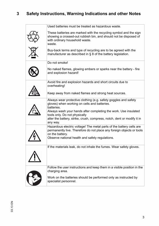
3
03.1
3 E
N3 Safety Instructions, Warning Indications and other Notes
Used batteries must be treated as hazardous waste.
These batteries are marked with the recycling symbol and the sign showing a crossed-out rubbish bin, and should not be disposed of with ordinary household waste. waste.
Buy-back terms and type of recycling are to be agreed with the manufacturer as described in § 8 of the battery legislation.
Do not smoke!
No naked flames, glowing embers or sparks near the battery - fire and explosion hazard!
Avoid fire and explosion hazards and short circuits due to overheating!
Keep away from naked flames and strong heat sources.
Always wear protective clothing (e.g. safety goggles and safety gloves) when working on cells and batteries. batteries. Always wash your hands after completing the work. Use insulated tools only. Do not physically alter the battery, strike, crush, compress, notch, dent or modify it in any way. Hazardous electric voltage! The metal parts of the battery cells are permanently live. Therefore do not place any foreign objects or tools on the battery.Observe national health and safety regulations.
If the materials leak, do not inhale the fumes. Wear safety gloves.
Follow the user instructions and keep them in a visible position in the charging area.
Work on the batteries should be performed only as instructed by specialist personnel.
3
03.1
3 E
N
3 Safety Instructions, Warning Indications and other Notes
Used batteries must be treated as hazardous waste.
These batteries are marked with the recycling symbol and the sign showing a crossed-out rubbish bin, and should not be disposed of with ordinary household waste. waste.
Buy-back terms and type of recycling are to be agreed with the manufacturer as described in § 8 of the battery legislation.
Do not smoke!
No naked flames, glowing embers or sparks near the battery - fire and explosion hazard!
Avoid fire and explosion hazards and short circuits due to overheating!
Keep away from naked flames and strong heat sources.
Always wear protective clothing (e.g. safety goggles and safety gloves) when working on cells and batteries. batteries. Always wash your hands after completing the work. Use insulated tools only. Do not physically alter the battery, strike, crush, compress, notch, dent or modify it in any way. Hazardous electric voltage! The metal parts of the battery cells are permanently live. Therefore do not place any foreign objects or tools on the battery.Observe national health and safety regulations.
If the materials leak, do not inhale the fumes. Wear safety gloves.
Follow the user instructions and keep them in a visible position in the charging area.
Work on the batteries should be performed only as instructed by specialist personnel.
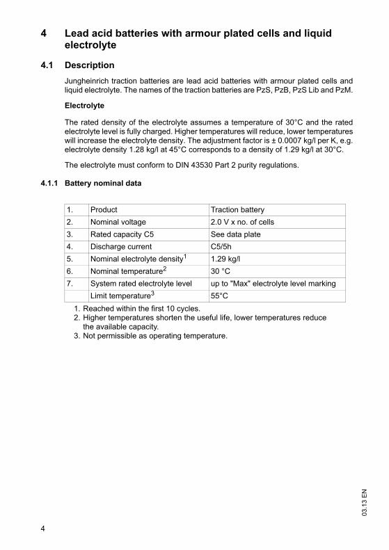
03.1
3 E
N
4
4 Lead acid batteries with armour plated cells and liquid electrolyte
4.1 Description
Jungheinrich traction batteries are lead acid batteries with armour plated cells andliquid electrolyte. The names of the traction batteries are PzS, PzB, PzS Lib and PzM.
Electrolyte
The rated density of the electrolyte assumes a temperature of 30°C and the ratedelectrolyte level is fully charged. Higher temperatures will reduce, lower temperatureswill increase the electrolyte density. The adjustment factor is ± 0.0007 kg/l per K, e.g.electrolyte density 1.28 kg/l at 45°C corresponds to a density of 1.29 kg/l at 30°C.
The electrolyte must conform to DIN 43530 Part 2 purity regulations.
4.1.1 Battery nominal data
1. Product Traction battery
2. Nominal voltage 2.0 V x no. of cells
3. Rated capacity C5 See data plate
4. Discharge current C5/5h
5. Nominal electrolyte density1
1. Reached within the first 10 cycles.
1.29 kg/l
6. Nominal temperature2
2. Higher temperatures shorten the useful life, lower temperatures reduce the available capacity.
30 °C
7. System rated electrolyte level up to "Max" electrolyte level marking
Limit temperature3
3. Not permissible as operating temperature.
55°C
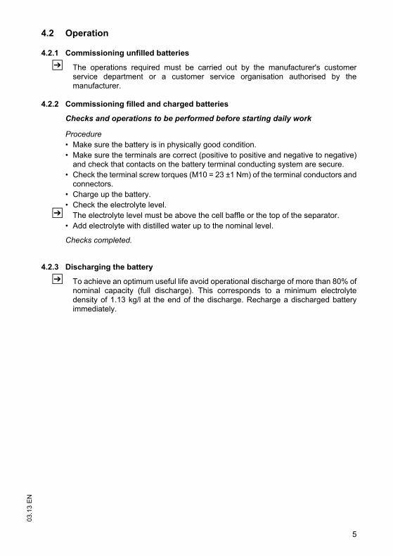
5
03.1
3 E
N4.2 Operation
4.2.1 Commissioning unfilled batteries
Z The operations required must be carried out by the manufacturer's customerservice department or a customer service organisation authorised by themanufacturer.
4.2.2 Commissioning filled and charged batteries
Checks and operations to be performed before starting daily work
Procedure• Make sure the battery is in physically good condition. • Make sure the terminals are correct (positive to positive and negative to negative)
and check that contacts on the battery terminal conducting system are secure.• Check the terminal screw torques (M10 = 23 ±1 Nm) of the terminal conductors and
connectors. • Charge up the battery.• Check the electrolyte level.
Z The electrolyte level must be above the cell baffle or the top of the separator.• Add electrolyte with distilled water up to the nominal level.
Checks completed.
4.2.3 Discharging the battery
Z To achieve an optimum useful life avoid operational discharge of more than 80% ofnominal capacity (full discharge). This corresponds to a minimum electrolytedensity of 1.13 kg/l at the end of the discharge. Recharge a discharged batteryimmediately.
5
03.1
3 E
N
4.2 Operation
4.2.1 Commissioning unfilled batteries
Z The operations required must be carried out by the manufacturer's customerservice department or a customer service organisation authorised by themanufacturer.
4.2.2 Commissioning filled and charged batteries
Checks and operations to be performed before starting daily work
Procedure• Make sure the battery is in physically good condition. • Make sure the terminals are correct (positive to positive and negative to negative)
and check that contacts on the battery terminal conducting system are secure.• Check the terminal screw torques (M10 = 23 ±1 Nm) of the terminal conductors and
connectors. • Charge up the battery.• Check the electrolyte level.
Z The electrolyte level must be above the cell baffle or the top of the separator.• Add electrolyte with distilled water up to the nominal level.
Checks completed.
4.2.3 Discharging the battery
Z To achieve an optimum useful life avoid operational discharge of more than 80% ofnominal capacity (full discharge). This corresponds to a minimum electrolytedensity of 1.13 kg/l at the end of the discharge. Recharge a discharged batteryimmediately.
03.1
3 E
N
6
4.2.4 Charging the battery
WARNING!
The gases produced during charging can cause explosionsThe battery gives off a mixture of oxygen and hydrogen (electrolytic gas) duringcharging. Gassing is a chemical process. This gas mixture is highly explosive andmust not be ignited.Always disconnect the charger and truck before connecting or disconnecting the
charger and battery.The charger must be adapted to the battery in terms of voltage, charge capacity
and battery technology.Before charging, check all cables and plug connections for visible signs of damage.Ventilate the room in which the truck is being charged.Battery cell surfaces must remain exposed during charging in order to ensure
sufficient ventilation, see truck operating instructions, chapter D, Charging theBattery.
Do not smoke and avoid naked flames when handling batteries.Wherever an industrial truck is parked for charging there must be no inflammable
material or consumables capable of creating sparks within a minimum distance of2 m from the truck.
Fire protection equipment must be available.Do not place any metallic objects on the battery.Always follow the safety regulations of the battery and charger station
manufacturers.
NOTE
The battery must only be charged with DC current. All charging processes inaccordance with DIN 41773 and DIN 41774 are permissible.
7
03.1
3 E
N
Z The electrolyte temperature rises by approx. 10 K during charging. Charging shouldtherefore only begin when the electrolyte temperature is below 45°C. Theelectrolyte temperature of batteries must be at least +10°C before charging.Otherwise the battery will not charge correctly. Below 10°C the battery isinsufficiently charged with standard charging systems.
Charging the battery
Requirements– Electrolyte temperature min. 10°C to max. 45°C
Procedure• Open or take off the tray lid or covers from the battery compartment.
Z Deviations are outlined in the truck's operating instructions. The plugs remain onthe cells or remain closed.
• Connect the battery to the switched off charger, ensuring the terminals are connect(positive to positive and negative to negative).
• Switch on the charger.
Battery charged
Z Charging is considered to be complete when the electrolyte density and batteryvoltage remain constant for more than 2 hours.
Compensation charging
Compensation charging is used to ensure the useful life and maintain capacity afterfull discharge and repeated insufficient charging. The maximum compensationcharge current is 5 A/100 Ah rated capacity.
Z Compensation charging should be carried out weekly.
Trickle charging
Battery trickle charging is partial charging that extends the daily application time.Higher average temperatures occur during trickle charging which reduce the usefullife of the batteries.
Z Trickle charges should only be performed when the charge level is below 60 %. Usereplacement batteries instead of regular trickle charging.
03.1
3 E
N
8
4.3 Servicing lead-acid batteries with armour plated cells
Water quality
Z The quality of the water used to fill up electrolyte must correspond to purified ordistilled water. Purified water can be produced through distillation or ionexchangers and is then suitable for the production of electrolyte.
4.3.1 Daily
– Charge the battery after each discharge.– After charging, check the electrolyte level.– If necessary, add purified water up to the rated level after charging.
Z The height of the electrolyte level should not be below the cell baffle or above thetop of the separator, or the "Min" and "Max" electrolyte markings respectively.
4.3.2 Weekly
– After re-charging, carry out a visual inspection for dirt and physical damage.– If the battery is charged regularly according to the IU characteristic, carry out a
compensation charge.
4.3.3 Monthly
– Towards the end of the charging process measure and record the voltages of allthe cells with the charger switched on.
– After charging measure and record the electrolyte density and the electrolytetemperature in all the cells.
– Compare the results with the previous ones.
Z If you find significant differences compared with the previous measurements ordifferences between the cells, contact the manufacturer's customer servicedepartment.
4.3.4 Annually
– Measure the truck insulation resistance in accordance with EN 1175-1.– Measure the battery insulation resistance in accordance with EN 1987-1.
Z In accordance with DIN EN 50272-3 the battery insulation resistance should not beless than 50 Ω per volt of rated voltage.
9
03.1
3 E
N5 PzV and PzV-BS lead-acid batteries with sealed armour
plated cells
5.1 Description
PzV batteries are sealed batteries with fixed electrolytes, to which no water can beadded over the entire lifespan of the battery. Relief valves are used as plugs whichare destroyed when opened. During operation the same safety requirements apply tothe sealed batteries as for batteries with liquid electrolyte. This is to avoid electricshock, explosion of the electrolyte charging gases or hazardous electrolyte burns ifthe cell vessels are destroyed.
Z PzV batteries are low gassing, but not gassing-free.
Electrolyte
The electrolyte is sulphuric acid which is fixed in gel. The density of the electrolytecannot be measured.
5.1.1 Battery nominal data
1. Product Traction battery
2. Nominal voltage 2.0 V x no. of cells
3. Rated capacity C5 See data plate
4. Discharge current C5/5h
5. Rated temperature 30 °C
Limit temperature1
1. Higher temperatures shorten the useful life, lower temperatures reduce the available capacity.
45°C, not permissible as operating temperature.
6. Rated density of the electrolyte Cannot be measured
7. System rated electrolyte level Cannot be measured
9
03.1
3 E
N
5 PzV and PzV-BS lead-acid batteries with sealed armour plated cells
5.1 Description
PzV batteries are sealed batteries with fixed electrolytes, to which no water can beadded over the entire lifespan of the battery. Relief valves are used as plugs whichare destroyed when opened. During operation the same safety requirements apply tothe sealed batteries as for batteries with liquid electrolyte. This is to avoid electricshock, explosion of the electrolyte charging gases or hazardous electrolyte burns ifthe cell vessels are destroyed.
Z PzV batteries are low gassing, but not gassing-free.
Electrolyte
The electrolyte is sulphuric acid which is fixed in gel. The density of the electrolytecannot be measured.
5.1.1 Battery nominal data
1. Product Traction battery
2. Nominal voltage 2.0 V x no. of cells
3. Rated capacity C5 See data plate
4. Discharge current C5/5h
5. Rated temperature 30 °C
Limit temperature1
1. Higher temperatures shorten the useful life, lower temperatures reduce the available capacity.
45°C, not permissible as operating temperature.
6. Rated density of the electrolyte Cannot be measured
7. System rated electrolyte level Cannot be measured
03.1
3 E
N
10
5.2 Operation
5.2.1 Commissioning
Checks and operations to be performed before starting daily work
Procedure• Make sure the battery is in physically good condition. • Make sure the terminals are correct (positive to positive and negative to negative)
and check that contacts on the battery terminal conducting system are secure.• Check the terminal screw torques (M10 = 23 ±1 Nm) of the terminal conductors and
connectors. • Re-charge the battery.• Charge the battery.
Check completed.
5.2.2 Discharging the battery
Z To achieve an optimum useful life avoid operational discharges of more than 60%of nominal capacity.
Z If the battery is discharged during operation by more than 80% of rated capacity theuseful life of the battery will reduce significantly. Fully or partially dischargedbatteries must be re-charged immediately and not left unattended.
5.2.3 Charging the battery
WARNING!
The gases produced during charging can cause explosionsThe battery gives off a mixture of oxygen and hydrogen (electrolytic gas) duringcharging. Gassing is a chemical process. This gas mixture is highly explosive andmust not be ignited.Always disconnect the charger and truck before connecting or disconnecting the
charger and battery.The charger must be adapted to the battery in terms of voltage, charge capacity
and battery technology.Before charging, check all cables and plug connections for visible signs of damage.Ventilate the room in which the truck is being charged.Battery cell surfaces must remain exposed during charging in order to ensure
sufficient ventilation, see truck operating instructions, chapter D, Charging theBattery.
Do not smoke and avoid naked flames when handling batteries.Wherever an industrial truck is parked for charging there must be no inflammable
material or consumables capable of creating sparks within a minimum distance of2 m from the truck.
Fire protection equipment must be available.Do not place any metallic objects on the battery.Always follow the safety regulations of the battery and charger station
manufacturers.
11
03.1
3 E
N
NOTE
Charging the battery incorrectly can result in material damage.Incorrect battery charging can result in overloading of the electric wires and contacts,hazardous gas formation and electrolyte leakage from the cells.Always charge the battery with DC current.All DIN 41773 charging procedures are permitted in the format approved by the
manufacturer.Always connect the battery to a charger that is appropriate to the size and type of
the battery.If necessary have the charger checked by the manufacturer's customer service
department for suitability.Do not exceed limit currents in the gassing area in accordance with DIN EN 50272-
3.
03.1
3 E
N
12
Charging the battery
Requirements– Electrolyte temperature between +15°C and 35°C
Procedure• Open or take off the tray lid or covers from the battery compartment.• Connect the battery to the switched off charger, ensuring the terminals are connect
(positive to positive and negative to negative). • Switch on the charger.
Z The electrolyte temperature rises by approx. 10 K during charging. If thetemperatures are permanently higher than 40°C or lower than 15°C, a temperature-dependent constant voltage control of the charger is required. The adjustmentfactor must be applied with -0.004 V/C per K.
Battery charged
Z Charging is considered to be complete when the electrolyte density and batteryvoltage remain constant for more than 2 hours.
Compensation charging
Compensation charging is used to ensure the useful life and maintain capacity afterfull discharge and repeated insufficient charging.
Z Compensation charging should be carried out weekly.
Trickle charging
Battery trickle charging is partial charging that extends the daily application time.Higher average temperatures occur during trickle charging which can reduce theuseful life of the batteries.
Z Trickle charges should only be performed when the charge level is below 50%. Usereplacement batteries instead of regular trickle charging.
Z Avoid trickle charging with PzV batteries.
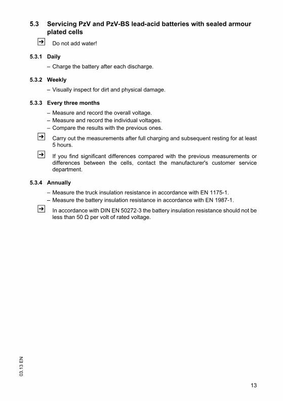
13
03.1
3 E
N5.3 Servicing PzV and PzV-BS lead-acid batteries with sealed armour
plated cells
Z Do not add water!
5.3.1 Daily
– Charge the battery after each discharge.
5.3.2 Weekly
– Visually inspect for dirt and physical damage.
5.3.3 Every three months
– Measure and record the overall voltage.– Measure and record the individual voltages.– Compare the results with the previous ones.
Z Carry out the measurements after full charging and subsequent resting for at least5 hours.
Z If you find significant differences compared with the previous measurements ordifferences between the cells, contact the manufacturer's customer servicedepartment.
5.3.4 Annually
– Measure the truck insulation resistance in accordance with EN 1175-1.– Measure the battery insulation resistance in accordance with EN 1987-1.
Z In accordance with DIN EN 50272-3 the battery insulation resistance should not beless than 50 Ω per volt of rated voltage.
13
03.1
3 E
N
5.3 Servicing PzV and PzV-BS lead-acid batteries with sealed armour plated cells
Z Do not add water!
5.3.1 Daily
– Charge the battery after each discharge.
5.3.2 Weekly
– Visually inspect for dirt and physical damage.
5.3.3 Every three months
– Measure and record the overall voltage.– Measure and record the individual voltages.– Compare the results with the previous ones.
Z Carry out the measurements after full charging and subsequent resting for at least5 hours.
Z If you find significant differences compared with the previous measurements ordifferences between the cells, contact the manufacturer's customer servicedepartment.
5.3.4 Annually
– Measure the truck insulation resistance in accordance with EN 1175-1.– Measure the battery insulation resistance in accordance with EN 1987-1.
Z In accordance with DIN EN 50272-3 the battery insulation resistance should not beless than 50 Ω per volt of rated voltage.
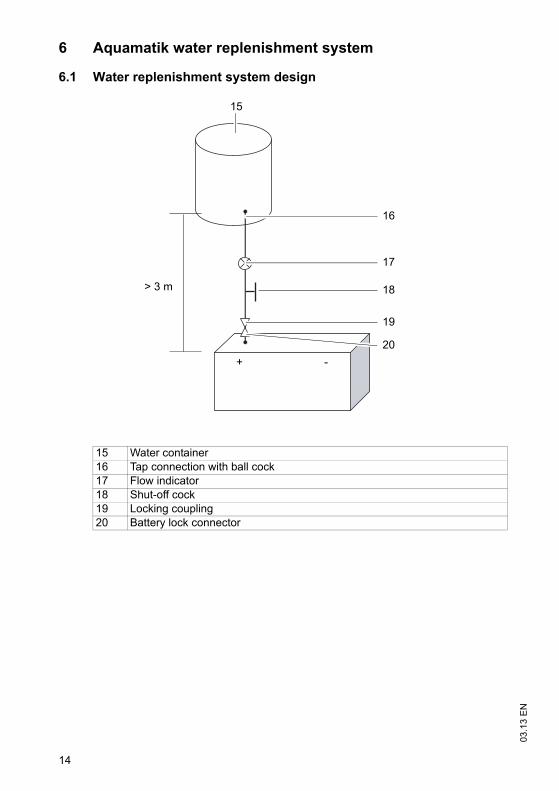
03.1
3 E
N
14
6 Aquamatik water replenishment system
6.1 Water replenishment system design
15 Water container16 Tap connection with ball cock17 Flow indicator18 Shut-off cock19 Locking coupling 20 Battery lock connector
15
16
17
18
19
20
> 3 m
+ -
03.1
3 E
N
14
6 Aquamatik water replenishment system
6.1 Water replenishment system design
15 Water container16 Tap connection with ball cock17 Flow indicator18 Shut-off cock19 Locking coupling 20 Battery lock connector
15
16
17
18
19
20
> 3 m
+ -
15
03.1
3 E
N6.2 Functional Description
The Aquamatik water replenishment system is used to adjust the rated electrolytelevel automatically on traction batteries for industrial trucks.
The battery cells are interconnected through hoses and are attached to the watersupply (e.g. water container) through a plug connection. When the shut-off cock isopened all the cells are filled with water. The Aquamatik plug controls the amount ofwater required and, at the relevant water pressures, ensures the water supply is shutoff and the valve is closed securely.
The plug systems have an optical level indicator, a diagnostic port to measure thetemperature and electrolyte density and a degassing port.
6.3 Adding water
Water should be added to the batteries just before the battery is fully charged. Thisensures that the amount of water added is mixed with the electrolyte.
6.4 Water pressure
The water replenishment system must be operated with a water pressure in the waterline of 0.3 bar - 1.8 bar. Any deviations from the permissible pressure ranges willaffect the operation of the systems.
Water drop
Assembly height above battery surface is between 3 - 18 m. 1 m corresponds to 0.1bar
Pressure water
The pressure regulating valve is adjusted to suit the system and must lie between 0.3- 1.8 bar.
15
03.1
3 E
N
6.2 Functional Description
The Aquamatik water replenishment system is used to adjust the rated electrolytelevel automatically on traction batteries for industrial trucks.
The battery cells are interconnected through hoses and are attached to the watersupply (e.g. water container) through a plug connection. When the shut-off cock isopened all the cells are filled with water. The Aquamatik plug controls the amount ofwater required and, at the relevant water pressures, ensures the water supply is shutoff and the valve is closed securely.
The plug systems have an optical level indicator, a diagnostic port to measure thetemperature and electrolyte density and a degassing port.
6.3 Adding water
Water should be added to the batteries just before the battery is fully charged. Thisensures that the amount of water added is mixed with the electrolyte.
6.4 Water pressure
The water replenishment system must be operated with a water pressure in the waterline of 0.3 bar - 1.8 bar. Any deviations from the permissible pressure ranges willaffect the operation of the systems.
Water drop
Assembly height above battery surface is between 3 - 18 m. 1 m corresponds to 0.1bar
Pressure water
The pressure regulating valve is adjusted to suit the system and must lie between 0.3- 1.8 bar.
03.1
3 E
N
16
6.5 Filling time
The filling time for a battery depends on the electrolyte level, the ambient temperatureand the filling pressure. Filling ends automatically. The water supply line must bedisconnected from the battery when the water has been filled.
6.6 Water quality
Z The quality of the water used to fill up electrolyte must correspond to purified ordistilled water. Purified water can be produced through distillation or ionexchangers and is then suitable for the production of electrolyte.
6.7 Battery tubing
The tubing of the individual plugs is in accordance with the existing electric circuit. Nochanges should be made.
6.8 Operating temperature
Batteries with automatic water replenishment systems should only be stored in roomswith temperatures > 0°C, as otherwise the systems could freeze.
17
03.1
3 E
N6.9 Cleaning measures
The plug systems must only be cleaned with purified water in accordance with DIN43530-4. No parts of the plugs must come into contact with solvent-based materialsor soap.
6.10 Service mobile vehicle
Mobile water filling vehicle with pump and filling gun to fill individual cells. Theimmersion pump in the container generates the necessary filling pressure. Theservice mobile must be at exactly the same height as the battery base.
17
03.1
3 E
N
6.9 Cleaning measures
The plug systems must only be cleaned with purified water in accordance with DIN43530-4. No parts of the plugs must come into contact with solvent-based materialsor soap.
6.10 Service mobile vehicle
Mobile water filling vehicle with pump and filling gun to fill individual cells. Theimmersion pump in the container generates the necessary filling pressure. Theservice mobile must be at exactly the same height as the battery base.
03.1
3 E
N
18
7 Electrolyte circulation
7.1 Functional Description
Electrolyte circulation ensures the supply of air during charging to mix the electrolyte,thereby preventing any acid layer, shortening the charge time (charge factor approx.1.07) and reducing the formation of gas during charging. The charger must besuitable for the battery and electrolyte circulation.
A pump in the charger produces the necessary compressed air which is introducedto the battery cells via a hose system. The electrolyte is circulated via the inlet air andthe electrolyte density level is constant over the entire length of the electrode.
Pump
In the event of a fault, e.g. if the pressure control system responds for an unknownreason, the filters must be checked and replaced if necessary.
Battery connection
A hose is attached to the pump module which together with the charge leads is routedfrom the charger to the charging connector. The air is passed on to the battery via theelectrolyte circulation coupling ducts in the connector. When routing make sure thehose is not bent.
Pressure monitoring module
The electrolyte circulation pump is activated when charging begins. The pressuremonitoring module monitors the build up of pressure during charging. This ensuresthat the required air pressure is provided for electrolyte circulation charging.
In the event of malfunctions such as:– Battery air coupling not connected to circulation module (if coupling is separate) or
faulty.– Leaky or faulty hose connections on battery or– Intake filter contaminated
a visual error message appears on the charger.
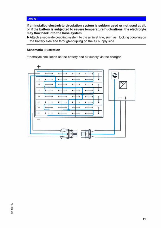
19
03.1
3 E
N
NOTE
If an installed electrolyte circulation system is seldom used or not used at all,or if the battery is subjected to severe temperature fluctuations, the electrolytemay flow back into the hose system.Attach a separate coupling system to the air inlet line, such as: locking coupling on
the battery side and through-coupling on the air supply side.
Schematic illustration
Electrolyte circulation on the battery and air supply via the charger.
03.1
3 E
N
20
8 Cleaning batteries
Batteries and trays must be cleaned in order to – maintain cell insulation and protect cells from ground or external conductive parts.– Avoid damage from corrosion and stray currents.– Avoid excessive and varying automatic discharge of the individual cells or block
batteries due to stray currents.– Avoid electric sparking due to stray currents.
When cleaning the batteries make sure that:– The assembly site chosen for cleaning is close to a drainage system for processing
the electrolytic rinsing water.– All health and safety as well as water and waste disposal regulations are observed
when disposing of used electrolyte or rinsing water.– Protective goggles and clothing are worn.– Cell plugs are not removed or opened.– Clean the plastic components of the battery, in particular the cell containers, only
with water or water-based cloths without any additives.– After cleaning, the top of the battery is dried with suitable equipment, e.g.
compressed air or cloths.– Any fluid that has entered the battery box must be suctioned off and disposed of in
accordance with the above-mentioned regulations.
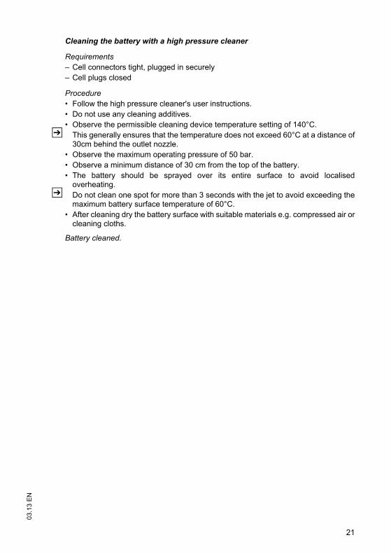
21
03.1
3 E
N
Cleaning the battery with a high pressure cleaner
Requirements– Cell connectors tight, plugged in securely– Cell plugs closed
Procedure• Follow the high pressure cleaner's user instructions.• Do not use any cleaning additives.• Observe the permissible cleaning device temperature setting of 140°C.
Z This generally ensures that the temperature does not exceed 60°C at a distance of30cm behind the outlet nozzle.
• Observe the maximum operating pressure of 50 bar.• Observe a minimum distance of 30 cm from the top of the battery.• The battery should be sprayed over its entire surface to avoid localised
overheating.Z Do not clean one spot for more than 3 seconds with the jet to avoid exceeding the
maximum battery surface temperature of 60°C.• After cleaning dry the battery surface with suitable materials e.g. compressed air or
cleaning cloths.
Battery cleaned.
03.1
3 E
N
22
9 Storing the battery
NOTE
The battery should not be stored for longer than 3 months without charging asotherwise it will no longer be functional.
If the battery is to be taken out of service for a long period, it should be stored fullycharged in a dry room protected from frost. To ensure the availability of the batterythe following charges can be selected:
– Monthly compensation charge for PzS and PzB batteries or 3-monthly full chargefor PzV batteries.
– Trickle charge for a charge voltage of 2.23 volts x no. of cells for PzS, PzM and PzBbatteries or 2.25 volts x no. of cells for PzV batteries.
If the battery is to be taken out of service for a long period ( > 3 months), it should, asfar as possible, be charged to 50% of its charge level and stored in a dry roomprotected from frost.
10 Troubleshooting
If any faults are found on the battery or charger, contact the manufacturer's customerservice department immediately.
Z The operations required must be carried out by the manufacturer's customerservice department or a customer service organisation authorised by themanufacturer.
11 Disposal
Batteries marked with the recycling symbol and the sign showing acrossed-out rubbish bin should not be disposed of with ordinaryhousehold waste.
Buy-back terms and type of recycling are to be agreed with themanufacturer as described in § 8 of the battery legislation.