Embed Size (px)
Citation preview

TESKOperating instructionsHinge safety switch
EN 1
1. About this document
1.1 FunctionThis operating instructions manual provides all the information you need for the mounting, set-up and commissioning to ensure the safe operation and disassembly of the safety switchgear. The operating instructions must be available in a legible condition and a complete version in the vicinity of the device.
1.2 Target group: authorised qualified personnelAll operations described in this operating instructions manual must be carried out by trained specialist personnel, authorised by the plant operator only.
Please make sure that you have read and understood these operating instructions and that you know all applicable legislations regarding occupational safety and accident prevention prior to installation and putting the component into operation.
The machine builder must carefully select the harmonised standards to be complied with as well as other technical specifications for the selection, mounting and integration of the components.
1.3 Explanation of the symbols used
Information, hint, note:This symbol is used for identifying useful additional information.
Caution: Failure to comply with this warning notice could lead to failures or malfunctions.Warning: Failure to comply with this warning notice could lead to physical injury and/or damage to the machine.
1.4 Appropriate useThe products described in these operating instructions are developed to execute safety-related functions as part of an entire plant or machine. It is the responsibility of the manufacturer of a machine or plant to ensure the correct functionality of the entire machine or plant.
The safety switchgear must be exclusively used in accordance with the versions listed below or for the applications authorised by the manufacturer. Detailed information regarding the range of applications can be found in the chapter "Product description".
1.5 General safety instructionsThe user must observe the safety instructions in this operating instructions manual, the country-specific installation standards as well as all prevailing safety regulations and accident prevention rules.
Further technical information can be found in the Schmersal catalogues or in the online catalogue on the Internet: www.schmersal.net.
The information contained in this operating instructions manual is provided without liability and is subject to technical modifications.
There are no residual risks, provided that the safety instructions as well as the instructions regarding mounting, commissioning, operation and maintenance are observed.
Content
1 About this document 1.1 Function . . . . . . . . . . . . . . . . . . . . . . . . . . . . . . . . . . . . . . . . . . . . . .11.2 Target group: authorised qualified personnel. . . . . . . . . . . . . . . . . .11.3 Explanation of the symbols used . . . . . . . . . . . . . . . . . . . . . . . . . . .11.4 Appropriate use . . . . . . . . . . . . . . . . . . . . . . . . . . . . . . . . . . . . . . . .11.5 General safety instructions . . . . . . . . . . . . . . . . . . . . . . . . . . . . . . .11.6 Warning about misuse . . . . . . . . . . . . . . . . . . . . . . . . . . . . . . . . . . .21.7 Exclusion of liability . . . . . . . . . . . . . . . . . . . . . . . . . . . . . . . . . . . . .2
2 Product description2.1 Ordering code . . . . . . . . . . . . . . . . . . . . . . . . . . . . . . . . . . . . . . . . .22.2 Special versions. . . . . . . . . . . . . . . . . . . . . . . . . . . . . . . . . . . . . . . .22.3 Destination and use . . . . . . . . . . . . . . . . . . . . . . . . . . . . . . . . . . . . .22.4 Technical data . . . . . . . . . . . . . . . . . . . . . . . . . . . . . . . . . . . . . . . . .22.5 Safety classification . . . . . . . . . . . . . . . . . . . . . . . . . . . . . . . . . . . . .3
3 Mounting3.1 General mounting instructions . . . . . . . . . . . . . . . . . . . . . . . . . . . . .33.2 Adjustment and inspection of the switching angle . . . . . . . . . . . . . .43.3 Dimensions . . . . . . . . . . . . . . . . . . . . . . . . . . . . . . . . . . . . . . . . . . .5
4 Electrical connection4.1 General information for electrical connection. . . . . . . . . . . . . . . . . .64.2 Contact variants . . . . . . . . . . . . . . . . . . . . . . . . . . . . . . . . . . . . . . . .64.3 Switch travel. . . . . . . . . . . . . . . . . . . . . . . . . . . . . . . . . . . . . . . . . . .6
5 Set-up and maintenance5.1 Functional testing. . . . . . . . . . . . . . . . . . . . . . . . . . . . . . . . . . . . . . .65.2 Maintenance . . . . . . . . . . . . . . . . . . . . . . . . . . . . . . . . . . . . . . . . . .6
6 Disassembly and disposal6.1 Disassembly. . . . . . . . . . . . . . . . . . . . . . . . . . . . . . . . . . . . . . . . . . .66.2 Disposal . . . . . . . . . . . . . . . . . . . . . . . . . . . . . . . . . . . . . . . . . . . . . .6
7 Appendix7.1 Wiring configuration and connector accessories . . . . . . . . . . . . . . .77.2 Door gap calculation . . . . . . . . . . . . . . . . . . . . . . . . . . . . . . . . . . . .87.3 Load specifications . . . . . . . . . . . . . . . . . . . . . . . . . . . . . . . . . . . . .9
8 EU Declaration of conformity
x.00
0 / 0
6.20
16 /
v.A
. -
103
0059
58-E
N /
B /
2016
-03-
16 /
AE
-Nr.
5816
EN Operating instructions. . . . . . . . . . . .pages 1 to 10Original

2
Operating instructionsHinge safety switch TESK
EN
1.6 Warning about misuse
In case of improper use or manipulation of the safety switch-gear, personal hazards or damages to machinery or plant components cannot be excluded when safety switchgear is used. The relevant requirements of the standard ISO 14119 must be observed.
1.7 Exclusion of liabilityWe shall accept no liability for damages and malfunctions resulting from defective mounting or failure to comply with this operating instructions manual. The manufacturer shall accept no liability for damages result-ing from the use of unauthorised spare parts or accessories.
For safety reasons, invasive work on the device as well as arbitrary re-pairs, conversions and modifications to the device are strictly forbidden; the manufacturer shall accept no liability for damages resulting from such invasive work, arbitrary repairs, conversions and/or modifications to the device.
2. Product description
2.1 Ordering codeThis operating instructions manual applies to the following types:
TESK-➀-➁-➂-➃-➄No. Option Description
➀ S Standard hingeL Long hinge half
➁ A Preset for front assemblyI Preset for inside assemblyU Freely adjustable switching angle
➂ 22 2 NO contacts / 2 NC contacts12 1 NO contacts / 2 NC contacts13 1 NO contacts / 3 NC contacts02 2 NC contacts11 1 NO contacts / 1 NC contacts
➃ L1 Cable downwardsL2 Cable upwardsST1 Connector plug bottomST2 Connector plug top
➄ 3M Cable length 3 m (only L1 / L2)5M Cable length 5 m (only L1 / L2)10M Cable length 10 m (only L1 / L2)20M Cable length 20 m (only L1 / L2)30M Cable length 30 m (only L1 / L2)
2.2 Special versionsFor special versions, which are not listed in the order code below 2.1, these specifications apply accordingly, provided that they correspond to the standard version.
2.3 Destination and useThe TESK hinge safety switch has been designed to prevent, in con-junction with the control part of a machine, movable safety guards from being opened before hazardous conditions have been eliminated. They are also suitable for fitting on profile sections and existing equipment.
Hinge safety switches can only be used for applications, in which the hazardous condition is terminated without delay (e.g. run-on movements) when the safety guard is opened.
The user must evaluate and design the safety chain in accordance with the relevant standards and on the required safety level.
The entire concept of the control system, in which the safety component is integrated, must be validated to the relevant standards.
2.4 Technical dataStandards: IEC 60947-5-1, BG-GS-ET-15 Enclosure: Zinc diecast, enclosure cover
self-extinguishing thermoplasticHinge pin: Galvanised steel / Steel C45Mounting: 4 x M6 screws DIN 7984 or ISO 4762
with TESK-L… 6 screws, Tightening torque 4.3 Nm
Contact material: Silver, gold-platedContact type: Change-over contact
with double break ZbSwitching system: IEC 60947-5-1; Slow action,
A positive break NC contactstermination: connector plug M12 or cableConnector plug: M12, 5-pole or 8-pole, A-codedConnection cable: Y-UL 2464 / 9 x AWG 22 / 9 x 0.34 mm²
Y-UL 2464 / 5 x AWG 22 / 5 x 0.34 mm²Temperature resistance of the cable: - at rest: -25°C ... +80°C - in motion: -5°C ... +80°CSwitching angle: 3° adjusted from zero pointForced opening angle: 10° adjusted from zero pointPositive break torque: 0.35 NmMax. swivel angle: 270°Actuating speed: max. 90° / 0.5 sBounce duration: in accordance with actuating speedSwitchover time: in accordance with actuating speedActuating frequency: max. 120 operations/hMechanical life: > 1 million switch cycles - Note: The mechanical life relates to an opening
angle of 90° without passing over the switch point. With pendulum flap functions that involve
moving over the switch point, the life cycle is reduced.Resistance to shock: 30 g / 11 msResistance to vibration: 10 ... 150 Hz,
amplitude 0.35 mmAmbient temperature: −25 °C … +65 °CStorage and transport temperature: −40 °C … +85 °CProtection class: IP65 to IEC 60529Protection class: - with cable: I - with connector plug M12, 8-pin: III - with connector plug M12, 5-pin: I

3
TESKOperating instructionsHinge safety switch
EN
Utilisation category: AC-15, DC-13Rated operating current/voltage Ie/Ue: -with cable: 2 A / 230 VAC 1 A / 24 VDC -with connector plug M12: 1 A / 24 VDCRated insulation voltage Ui: - with cable: 300 V - with connector plug, M12 8-pin: 30 V (PELV to DIN EN 60204-1) - with connector plug, M12 5-pin: 60 VRated impulse withstand voltage Uimp: - with cable: 2.5 kV - with connector plug, M12 8-pin: 0.5 kV - with connector plug, M12 5-pin: 0.8 kVThermal test current Ithe: 2.5 ARated operating voltage Ue max: - with cable: 230 V - with connector plug M12, 8-pin: 30 V - with connector plug M12, 5-pin: 60 VMax. fuse rating: 2 A gG D-fuseSwitching of low voltages: 1 mA / 3 VDCMechanical breaking load (see fig. 1): - F1: 5,000 N - F2: 5,000 N
See Section 7.3 Load details
F1
F2
F1
F2
Fig. 1
C For use in NFPA 79 Applications only.
2.5 Safety classificationStandards: ISO 13849-1Envisaged structure: - Basically: applicable up to Cat. 1 / PL c - With 2-channel usage and
fault exclusion mechanism*: applicable up to Cat. 3 / PL d with suitable logic unit
B10d NC contact: 2,000,000B10d NO contact at 10% ohmic contact load: 1,000,000Service life: 20 years* If a fault exclusion to the 1-channel mechanics is authorised.
MTTFB d x xh s/h3600
d10d op op
opn0,1 x nop t cycle
(Determined values can vary depending on the application-specific parameters hop, dop and tcycle as well as the load.)
If multiple safety components are wired in series, the Performance Level to ISO 13849-1 will be reduced due to the restricted error detection under certain circumstances.
3. Mounting
3.1 General mounting instructions
During fitting of the actuator and the sensor, the requirements of ISO 14119, especially paragraph 7 must be observed!
Four elongated holes are provided for fixing the switch. To facilitate the alignment of the door to the post, alignment pins are supplied (not for indoor use) that can be inserted into corresponding holes on the bottom of the hinge switch (Fig. 2). Once installed, these can be removed again.
Fig. 2
When used in applications with function for the protection of man, the components must be fitted so that disassembly is prevented (e.g. drill out the hexagonal recess of the fixing screws, blocking the hexagonal recess using a plastic cone diameter 5.1 mm).
The hinge switch furthermore must be pinned after assembly and adjustment (Fig. 3).
A) A)
Fig. 3
KeyA = Drill and pin in this area
Any mounting position. The mounting position however is chosen so that the components are preferably fitted in the upper part of the safety guard to avoid the ingress of dirt and soiling as well as damage to the components. In case of painting activities, the components must be covered. Recommended mounting material, see technical data.We recommend that the fixing screws are painted after the component is fitted and to apply the accompanying caps (Figure 4.)

4
Operating instructionsHinge safety switch TESK
EN
The minimum bending radius must be observed for versions with a cable connection!
Please note the load information "Determining the permissible forces as a function of door size and number of hinges" (see Section 7.3 Load details)
The hinge safety switch must not be used as an end stop. For applications in which heavy doors are used and for use on hoods, especially if these can close with little or no braking effect, further measures are to be implemented to prevent the securing bolts from working loose. A reduction in the service life is also expected. The use of hydraulic struts on hoods is not permitted as otherwise the hinge switch would be damaged beyond repair.
Fig. 4
Please observe the relevant requirements of the standards ISO 12100, ISO 14119 and ISO 14120. Also observe the safety distances to the standards ISO 13857 and EN 349.
3.2 Adjustment and inspection of the switching angleAfter the switch has been fitted, the switching function and the opening angle of the safety guard must be checked. The switching angle of the NC contacts set in factory is approximately 3°.
Caution: for the TESK...-U version, the following paragraph "Special instructions for the on-site setting" must be observed!
Special instructions for the on-site setting (version TESK...-U)We recommend a setting including the following steps:1. Open guard system up to maximum permissible door gap
(see table chapter 7.2 Determining door gap).2. Use the adjustment tool to set the normally-closed contacts in such
a way that they are securely opened with the maximum permissible door gap. Turning clockwise results in a smaller switch angle while turning anticlockwise results in a larger switch angle (fig. 6); this is the opposite when mounted inside. To decrease the switching angle, turn counterclockwise to increase the switching angle (Fig. 6); when mounted inside accordingly reversed.The positive break angle is 7° larger than the set switching angle.
3. After the switch is set, the compliance of the switch with the safety-technical requirements of the application must be checked (see Section 7.2 Door gap calculation).
4. After the switching angle has been set and checked, the blanking plug for the adjustment opening located at the rear of the adjustment tool must be inserted in the adjustment opening (1) and torn down by making lateral movements (2) with the tool (Fig. 7).
-
+1
2
Fig. 6 Fig. 7
After the desired switching point is set, the opening of the set-ting option imperatively must be sealed with a blanking plug.This measure prevents tampering at the set switching point within the meaning of ISO 14119 paragraph 5.7 and therefore avoids any loss of the safety function of the device.The blanking plug is injected to the special adjustment tool with a predetermined breaking point.We recommend an additional painting or glueing of the blanking plug.Securing the setting screw by means of the blanking plug is a mandatory instruction for the user, which must be oberved in order to maintain the CE-Conformity of the component.
5
TESKOperating instructionsHinge safety switch
EN
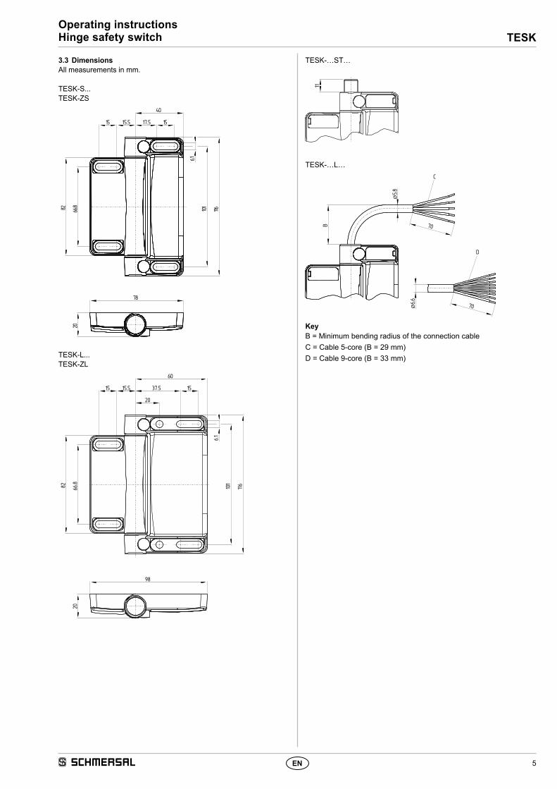
3.3 DimensionsAll measurements in mm.
TESK-S...TESK-ZS
116101
6.1
66.882
20
78
15 15.5 15
40
17.5
TESK-L...TESK-ZL
60
15 15.5 37.5 15
20
6.1
116
66.882
20
98
101
TESK-…ST…
11
TESK-…L…
Ø 6.6
70
70
B
Ø 5.8
C
D
KeyB = Minimum bending radius of the connection cable C = Cable 5-core (B = 29 mm)D = Cable 9-core (B = 33 mm)

6
Operating instructionsHinge safety switch TESK
EN
4. Electrical connection
4.1 General information for electrical connection
The electrical connection may only be carried out by authorised personnel in a de-energised condition. For the connection of different connector versions only connectors with the appropriate protection rating may be used.
The versions TESK-…-22ST… and TESK-…-13ST… and TESK-...-12ST...should only be used PELV circuits in accordance to EN 60204.
4.2 Contact variantsContacts are shown with safety guard closed.
TESK-…22L… TESK-…13L…WH 11VT 23
12 BK24 RD
BN 31 32 BUGY 43 44 PK
PE GN/YE
WH 11VT 23
12 BK24 RD
BN 31 32 BUGY 41 42 PK
PE GN/YE
TESK-…12L… TESK-…02L…
WH 11VT 23
12 BK24 RD
BN 31 32 BUPE GN/YE
BN 21 22 BU12 BKWH 11
PE GN/YE
TESK-…11L…
WH 11BN 23
12 BK24 BUPE GN/YE
TESK-…22ST… TESK-…13ST… 11
23
12
2431 32
1 2 3 4 5 6 7 8
43 44
5
8
4
3
21
7
6
11
23
12
2431 32
41 42
1 2 3 4 5 6 7 8
5
8
4
3
21
7
6
TESK-…12ST… TESK-…02ST…
11
23
12
2431 32
1 2 3 4 5 6 7 8
5
8
4
3
21
7
6
11
21
12
22PE
1 2 3 4 5
3
25
1
4
TESK-…11ST… 11
23
12
24PE
1 2 3 4 5
3
25
1
4
4.3 Switch travel
TESK-...22... TESK-...13...(10°) 180°3°
11-12
31-3243-44
23-24A
A
(10°) 180°3°
11-12
31-3241-42
23-24A
AA
TESK-...12... TESK-...02...(10°) 180°3°
11-12
31-3223-24
A
A
(10°) 180°3°
11-1221-22
AA
TESK-...11...(10°) 180°3°
11 - 1223 - 24
A
KeyA Positive break NC contactT Positive break travel / -angle
(Switching angle tolerance -1° / +3°)
5. Set-up and maintenance
5.1 Functional testingThe safety function of the safety components must be tested. The following conditions must be previously checked and met:1. Correct fixing of the component2. Check the integrity of the cable entry and connections3. Check the switch enclosure for damage
5.2 MaintenanceA regular visual inspection and functional test, including the following steps, is recommended:1. Check fitting of the hinge safety switch2. Remove particles of dust and soiling3. Check cable entry and connections4. Examination of the switching angle
Damaged or defective components must be replaced.
6. Disassembly and disposal
6.1 DisassemblyThe safety switchgear must be disassembled in a de-energised condition only.
6.2 DisposalThe safety switchgear must be disposed of in an appropriate manner in accordance with the national prescriptions and legislations.

7
TESKOperating instructionsHinge safety switch
EN
7. Appendix
7.1 Wiring configuration and connector accessories
Connector plug ST M12, 5-pole3
25
1
4
Pin configuration of the connector
Colour code or conductor numbering
of the below-mentioned Schmersal connectors
Possible colour code of other commercially available connectors
to EN 60947-5-2: 2007 DIN 47100
Connecting cables with female connector IP67, M12, 5-pole - 5 x 0.25 mm²
1 BN 1 BN WH2 WH 2 WH BN
Cable length Part number 3 BU 3 BU GN5.0 m15.0 m
103010816103010820
4 BK 4 BK YE5 GY 5 GY GY
Connector plug ST2 M12, 8-pole5
8
4
3
21
7
6
Pin configuration of the connector
Colour code or conductor numbering
of the below-mentioned Schmersal connectors
Possible colour code of other commercially available connectors
to EN 60947-5-2: 2007 DIN 47100
Connecting cables with female connector IP67, M12, 8-pole - 8 x 0.23 mm²
1 BN 1 BN WH2 WH 2 WH BN
Cable length Part number 3 BU 3 BU GN2.5 m5.0 m10.0 m
103011411103011412103011413
4 BK 4 BK YE5 GY 5 GY GY6 VT 6 PK PK
Connecting cables with female connector IP69K, M12, 8-pole - 8 x 0.21 mm²
7 RD 7 VT BU8 PK 8 OR RD
Cable length Part number5.0 m5.0 m
101210560101210561 (angled)
Colour code keyCode Colour Code Colour Code Colour Code Colour
BK black GN green PK pink WH whiteBN brown GY grey RD red YE yellowBU blue OR orange VT violet

8
Operating instructionsHinge safety switch TESK
EN
7.2 Door gap calculationCalculation of the door gap depending on the opening angle, door width and overlapping
β 3° 4° 5° 6° 7° 8° 9° 10°C D100 5.2 7.0 8.7 10.4 12.2 13.9 15.6 17.4150 7.8 10.5 13.1 15.7 18.3 20.9 23.5 26.0200 10.5 13.9 17.4 20.9 24.4 27.8 31.3 34.7250 13.1 17.4 21.8 26.1 30.5 34.8 39.1 43.3300 15.7 20.9 26.1 31.3 36.5 41.7 46.9 52.1350 18.3 24.4 30.5 36.6 42.6 48.7 54.7 60.7400 20.9 27.9 34.8 41.8 48.7 55.6 62.5 69.4450 23.5 31.4 39.2 47.0 54.8 62.6 70.4 78.1500 26.2 34.9 43.6 52.2 60.9 69.6 78.2 86.8550 28.8 38.3 47.9 57.5 67.0 76.5 86.0 95.5600 31.4 41.8 52.3 62.7 73.1 83.5 93.8 104.1650 34.0 45.3 56.6 67.9 79.2 90.4 101.6 112.8700 36.6 48.8 61.0 73.1 85.3 97.4 109.4 121.5750 39.2 52.3 65.3 78.4 91.4 104.3 117.3 130.2800 41.8 55.8 69.7 83.6 97.4 111.3 125.1 138.8850 44.5 59.3 74.0 88.8 103.5 118.2 132.9 147.5900 47.1 62.7 78.4 94.0 109.6 125.2 140.7 156.2950 49.7 66.2 82.8 99.3 115.7 132.1 148.5 164.9
1,000 52.3 69.7 87.1 104.5 121.8 139.1 156.4 173.61,050 54.9 73.2 91.5 109.7 127.9 146.1 164.2 182.21,100 57.5 76.7 95.8 114.9 134.0 153.0 172.0 190.91,150 60.2 80.2 100.2 120.1 140.1 160.0 179.8 199.61,200 62.8 83.7 104.5 125.4 146.2 166.9 187.6 208.31,250 65.4 87.2 108.9 130.6 152.3 173.9 195.4 217.01,300 68.0 90.6 113.2 135.8 158.4 180.8 203.3 225.61,350 70.6 94.1 117.6 141.0 164.4 187.8 211.1 234.31,400 73.2 97.6 122.0 146.3 170.5 194.7 218.9 243.01,450 75.8 101.1 126.3 151.5 176.6 201.7 226.7 251.71,500 78.5 104.6 130.7 156.7 182.7 208.7 234.5 260.3
β = Door opening angleC = Door width in mmD is the door gap in mm with an overlap at B = 0 mm.B is the thickness of the door
The actual door gap "D1" is calculated using door gap "D" calculated by means of the table above minus the overlapping "B" of door and frame:D1 = D – B
C
β
D1 D
B
Example: A door made of 40 mm aluminium profile with a length of 950 mm should be secured with a TESK. The safety contact of the TESK opens to 3° when new according to the technical safety sheet (10° at the end of its service life). The table above shows the door gap when new at ap-prox. 49.7 mm. The real door gap can be calculated with the following equation D1 = D – B; (49.7 – 40 = 9.7); D1 = 9.7 mm. At the end of the service life the door gap is approx. 164.9 mm and the real door gap is (164.9 – 40 = 124.9); D1 = 124.9 mm.

9
TESKOperating instructionsHinge safety switch
EN
Doors with two hinges
Force [N] B [mm]
400 500 600 700 800 900 1000 1100 1200H [mm] up to 1000 400 400 400 400 400 400 400 400 350
up to 1800 400 400 400 400 350 350 300 300 250 up to 2400 400 400 400 300 250 250 200 200 150 up to 2600 400 400 300 200 150 150 100 100 50
not recommended
Doors with three hinges
Force [N] B [mm]
400 500 600 700 800 900 1000 1100 1200 1300 1400 1500H [mm] up to 1800 750 750 750 700 650 650 600 600 550 500 450 400
up to 2400 750 750 700 600 550 550 500 500 450 400 350 300 up to 2600 750 700 600 500 450 450 400 400 400 400 350 300
B D C
F 0.55 x H
H/8
H/5
H/8
H/5
H/5
0.6 x H H
C = Use of one hinge switch and an additional hingeD = Use of one hinge switch and two additional hinges
With larger doors the have three hinges make sure the two of the hinges are located in the upper third.
We recommend that the safety hinge switch is placed in the middle when three hinges are used.
The hinge safety switch must not be used as an end stop. For applications in which heavy doors are used, especially if these can close with little or no braking effect, further measures are to be implemented to prevent the securing bolts from working loose. If necessary, damping/braking measures may be required.
For applications with a different assembly, e.g. hoods, a reduced service life is expected.
If necessary, damping or braking measures may need to be implemented.
7.3 Load specificationsDetermining the permissible forces as a function of door size and number of hinges.
Doors with one hinge
Force [N] B [mm]
100 200 300 400 500H [mm] up to 200 200 150 100 70 50
up to 300 200 150not recommen-
ded
B
F
H/2
H/2
H
The hinge should be placed in the middle with doors that only have one hinge.

10 EN
TESK
-B-E
N
Operating instructionsHinge safety switch TESK
8. EU Declaration of conformity
The currently valid declaration of conformity can be downloaded from the internet at www.schmersal.net.
Name of the component: TESK
Type: See ordering code
Description of the component: Hinge safety switch
Relevant Directives: Machinery DirectiveRoHS-Directive
2006/42/EC2011/65/EU
Applied standards: DIN EN 60947-5-1:2010,DIN EN ISO 14119:2014
Person authorized for the compilation of the technical documentation:
Oliver WackerMöddinghofe 3042279 Wuppertal
Place and date of issue: Wuppertal, April 20, 2016
Authorised signaturePhilip SchmersalManaging Director
EU Declaration of conformity
Original K.A. Schmersal GmbH & Co. KGMöddinghofe 3042279 WuppertalGermanyInternet: www.schmersal.com
We hereby certify that the hereafter described components both in their basic design and construction conform to the applicable European Directives.
K. A. Schmersal GmbH & Co. KGMöddinghofe 30, D - 42279 WuppertalPostfach 24 02 63, D - 42232 Wuppertal
Phone: +49 - (0)2 02 - 64 74 - 0 Telefax: +49 - (0)2 02 - 64 74 - 1 00E-Mail: [email protected]: http://www.schmersal.com