Embed Size (px)
Citation preview

MultiSystem 5060 PlusUniversal Portable Measuring System
Firmware Version 6.8Manual Version 3.0 EN
Operating Instructions
EN

Contents
Firmware Version 6.8 MultiSystem 5060 Plus
EN
Safety
General safety and warning information ............. 4
Handling information for the MultiSystem 5060 Plus...................................... 5
Information about the use of sensors and cables........................................................... 6
Information about handling batteries................... 7
Information about the connection of printers....... 7
Introduction
Range of validity ................................................. 8
Copyright............................................................. 9
Limitation of liability........................................... 10
Intended use ..................................................... 11
Warranty ........................................................... 12
Customer obligations ........................................ 13
Authorized personnel ........................................ 13
Description of the measuring instrument
Properties of the MultiSystem 5060 Plus ........ 14
Connections ...................................................... 15
Characteristics of highspeed analogue inputs ........................................... 16
Characteristics of analogue inputs............... 17
Characteristics of frequency inputs.............. 18
Characteristics of digital signal input............ 19
Characteristics digital signal output ............. 19
Characteristics combi-jack CAN / RS 232 ... 20
Characteristics USB interfaces .................... 21
Display .............................................................. 22
Keyboard........................................................... 23
HYDROcom software package ......................... 24
Technical data................................................... 24
Commissioning
Check delivery .................................................. 25
Scope of delivery .............................................. 26
Charge batteries ............................................... 27
Operation
Switch the instrument On and Off..................... 29
Select operating language................................ 30
Set date and time.............................................. 31
Connect sensors............................................... 32
Enter sensor parameters .................................. 33
Record measuring data .................................... 35
Connect a PC and transfer measurement data 37
Delete measuring data...................................... 38
Print measuring data......................................... 39
Reset device ..................................................... 40
Operating software
Measured values display .................................. 41
Measured values with MinMax .................... 42
Measured values with their units ................. 43
Menu................................................................. 44
Available submenus .................................... 45
Available functions....................................... 45
Channels submenu........................................... 48
Display submenu .............................................. 58
Display scaling dialogue .............................. 62
Graphic menu dialogue ............................... 63
Memory submenu ............................................. 64
Device submenu............................................... 71
Dialogue Setup (1/2).................................... 82
Dialogue Setup (2/2) - Calibr. interval ......... 86
Software Info dialogue................................. 87
Projects submenu ............................................. 88
Special applications submenu .......................... 90
HYDROrun .................................................. 91
CANopen device.......................................... 96
Patrick the Particle Counter......................... 97
Load valve ................................................. 105
Presentation function ...................................... 116
Presentation type table.............................. 123
Presentation type graph ............................ 124
Dialogue Setup for Presentation................ 127
Delete series function ..................................... 129
USB stick menu function................................. 130

Contents
Firmware Version 6.8 MultiSystem 5060 Plus
EN
Special functions
Linearisation table........................................... 136
Define CAN channel ....................................... 138
Graphic presentation in display menu............. 142
Couple several instruments ............................ 143
Connecting a measuring instrument electrically .................................................. 143
Programming instruments.......................... 147
Start recording ........................................... 148
Transfer and evaluate measured values.... 149
How to use the USB stick ............................... 149
Firmware update using the USB Stick ............ 150
Connect MultiXtend A and T ........................... 151
Activate CAN bus....................................... 152
Program CAN channels ............................. 153
Activate MultiXtend power supply .............. 155
Start the MultiXtend ................................... 155
Connection of external measuring devices ..... 156
Viscosity-compensated volume flow rate measuring ................................................ 157
Cleaning and maintenance
Cleaning.......................................................... 162
Maintenance ................................................... 163
Repair ............................................................. 164
Manufacturer address and customer service.. 165

Firmware Version 6.8 MultiSystem 5060 Plus 4
Safety
EN
Safety
General safety and warning information
• Never cut, damage or modify the power pack cables or place things on it.
• Never touch the power pack with wet or moist hands.
• Only connect the power pack to power supplies for which it is suited (see Chapter Technical data on page 24),
• Unplug the mains cable from the outlet during a thunderstorm.
• Unplug the mains cable if you detect smoke or smell, or if the mains cable is damaged.
• Ensure sufficient grounding of your installations. Inadequate grounding may lead to measuring peaks.
Firmware Version 6.8 MultiSystem 5060 Plus 5
Safety
EN
Handling information for the MultiSystem 5060 Plus
• Never expose the instrument to excessive heat or moisture and observe the technical data.
• Do not store the instrument in humid or dusty locations or at temperatures below freezing point.
• Never submerge the instrument into water or other liquids. Never let liq-uids come into the instrument.
• Never open the instrument.
• Do not use the instrument if it has been dripped or if the casing is damaged.
• Avoid strong magnetic fields. Keep the instrument away from electric motors or other devices which generate electromagnetic fields. Strong magnetic fields may cause malfunctions and influence measuring values.
• Prevent the formation of condensed water. If condensed water has formed you should let the instrument acclimate before you switch it on.

Firmware Version 6.8 MultiSystem 5060 Plus 6
Safety
EN
Information about the use of sensors and cables
• Protect the sensors from exceeding the allowed power range, mechanicaloverload and incorrect pin assignment.
• Make sure you enter the sensor parameters correctly when using sensorswithout ISDS (Intelligent Sensor Detection System).
• The measuring cables MK 01 and MKS may not be lengthened. Otherwisethe shielding will be interrupted.
• The data of an ISDS sensor are read in when the measuring instrument isswitched on. If sensors are reconnected the measuring instrument mustbe switched off and on again to allow the sensor data to be adopted.

Firmware Version 6.8 MultiSystem 5060 Plus 7
Safety
EN
Information about handling batteries
• Always keep batteries away from heat sources and open fire.
• Never submerge batteries into water.
• Never disassemble, repair or modify the batteries.
• Never short-circuit the contacts of batteries.
• Use only batteries that are installed or delivered by HYDROTECHNIK.
• Only charge the battery while it is mounted in the instrument.
• Dispose of used batteries as hazardous waste. Cover the contacts withinsulation tape.
Information about the connection of printers
The measuring instrument supports printers with USB interface. Due to the wide variety of printers on the market, it is not possible to ensure support for all of them. In addition, the basic USB specifications are not fulfilled and main-tained completely by all manufacturers. For this reason, HYDROTECHNIK only guarantees the full support of the printer PIXMA iP4200 from Canon Inc. Please ask our customer service, whether your printer is supported.
Disposal informationDo not dispose of this product with your household waste.You can find more detailed information on disposal on our website at: www.hydrotechnik.com

Firmware Version 6.8 MultiSystem 5060 Plus 8
Introduction
EN
Introduction
Range of validity
The manual on hand is valid for measuring instruments named MultiSystem 5060 Plus. It is intended for the operator of this instrument, that means the person who works with the instrument. The manual is not a techni-cal manual. Please contact our customer service for questions, that go beyond the contents of this manual.
The information contained in this section is important. If you neglect them, you might loose possible guarantee demands.

Firmware Version 6.8 MultiSystem 5060 Plus 9
Introduction
EN
Copyright
The measuring instrument and this manual are protected by copyright. Repro-duction without license will be prosecuted. All rights reserved to this manual; this includes the reproduction and/or duplication in any conceivable form, e.g. by photocopying, printing, on any data recording media or in translated form. Reproduction of this manual is only permitted with a written approval of HYDROTECHNIK GmbH.
The technical state by the time of delivery of instrument and manual is deci-sive, if no other information is given. Technical changes without special announcements are reserved. Earlier manuals are no longer valid.
The general conditions of sale and delivery of HYDROTECHNIK GmbH are valid.

Firmware Version 6.8 MultiSystem 5060 Plus 10
Introduction
EN
Limitation of liability
We guarantee the faultless functioning of our product in accordance with our advertising, the product information by Hydrotechnik GmbH and this manual. Further product features are not guaranteed. We take no liability for the econ-omy and faultless function if the product is used for a different purpose than that, described in the chapter Intended use.
Compensation claims are generally excluded, except if intention or culpable negligence by HYDROTECHNIK is proved, or if assured product features are not provided. If the product is used in environments, for which it is not suited or which do not represent the technical standard, we shall not be responsible for the consequences.
We shall assume no liability for damages to installations and systems in the surroundings of the product, which are caused by a fault of the product or an error in this manual.
We are not responsible for the violation of patents and/or other rights of third persons outside the Federal Republic of Germany.
We are not liable for damages, which result from improper operation and non-compliance with the instructions in this manual. We are not liable for lost profits and for consequential damages that arise from non-compliance with safety and warning information. We shall assume no liability for damages which re-sult from the use of accessories and wear parts that were not delivered and/or approved by HYDROTECHNIK.
The products of HYDROTECHNIK GmbH are designed for a long life. They represent the state-of-the-art and their functions have been individually checked before delivery. The electrical and mechanical construction corre-sponds to the current norms and regulations. HYDROTECHNIK conducts ongoing product and market research for the further development and contin-uous improvement of its products.
In case of faults and/or technical trouble please contact HYDROTECHNIK customer service. We can assure that we will take immediate measures. The guarantee conditions of HYDROTECHNIKapply; if desired, we will gladly send you these.

Firmware Version 6.8 MultiSystem 5060 Plus 11
Introduction
EN
Intended use
The measuring instrument MultiSystem 5060 Plus is a mobile, hand-held in-strument for the recording, storage and evaluation of measuring data, collected by sensors connected to the device.
You can connect a large variety of different sensors to the instrument, but they have to meet the requirements defined in the section Technical data. Any oth-er use of the measuring instrument is considered improper. If you have any question or want to use the measuring instrument for a different purpose, please do not hesitate to contact our service staff. We will be happy to assist you with any possibly necessary configurations.

Firmware Version 6.8 MultiSystem 5060 Plus 12
Introduction
EN
Warranty
In accordance with our warranty conditions, we guarantee the condition with-out defects for this measuring instrument for a duration of six months. Wearing parts and storage batteries are excluded from this warranty. The warranty be-comes void if repair work or interventions are executed by unauthorized persons.
Within the warranty period we will repair damage or defects which are caused by a manufacturing fault. We only accept warranty claims if they are reported to us immediately after their discovery, but no later than six months after deliv-ery. The warranty benefit is by our choice through free repair of defective parts or replacement by sound parts.
Please send the devices, for which you have made a guarantee claim, to us carriage paid and with a copy of the invoice resp. the delivery slip to the HYDROTECHNIK customer service. You can find the address at the end of this manual.

Firmware Version 6.8 MultiSystem 5060 Plus 13
Introduction
EN
Customer obligations
The operating authority of this product has to assure, that only persons who
• know the regulations on working safety and accident prevention
• have been instructed in the operation of this product
• have read and understood this manual
are permitted to operate this product. Persons who operate this instrument are obliged to
• obey all regulations on working safety and accident prevention
• read this manual completely, especially the safety instructions in the first chapter.
Authorized personnel
Persons are considered to be authorized if they have a professional education, technical experience, knowledge of the relevant norms and regulations and if they are able to estimate their duties and recognize possible danger at an ear-ly time.
Operator of the instrument
Persons are considered to be authorized if they have been instructed in the operation of the instrument and have read and understood this manual completely.
Personnel for installation and maintenance
Persons are considered to be authorized if they have been trained in all as-pects of the instrument and have read and understood this manual completely.

Firmware Version 6.8 MultiSystem 5060 Plus 14
Description of the measuring instrument
EN
Description of the measuring instrument
Properties of the MultiSystem 5060 Plus
The MultiSystem 5060 Plus is a practice-oriented, user-friendly hand-held measuring instrument supporting the user in the daily measuring functions. When using sensors with ISDS (intelligent sensor detection), the MultiSystem 5060 Plus automatically identifies the connected sensors during switch-on and adopts all parameters: Measurement range, physical measure-ment variables, unit of measurement, signal output and characteristic curve (linearisation). You can also connect sensors without ISDS designation. The entry of the sensor parameters is then done in clear operation menus.
All measurements can be conveniently transferred to a PC using a USB cable. The software HYDROcom is delivered for free with the instrument and offers comprehensive support with functions for the evaluation, presentation and printing of the measured values.
You can connect up to eight sensors and store all measured values. Calcula-tions from the measured values as difference, sum and performance, and a first differentiation (e.g. speed from distance) are available as additional spe-cial channels for display and storage. The buffering of extreme values of the minimum and maximum measurands is always active and can be displayed by the corresponding key selection.

Firmware Version 6.8 MultiSystem 5060 Plus 15
Description of the measuring instrument
EN
Connections
A USB – host interfaceB USB – device interfaceC Combi-jack CAN/RS232D Input C7 – frequency inputE Input C5 – analogue inputF Input C3 – analogue inputG Input C1 – analogue input highspeed
H Input C2 – analogue input highspeedI Input C4 – analogue inputJ Input C6 – analogue inputK Input C8 – frequency inputL Power supply – power packM Digital input and output
A CB D E F G
H
I
J
K
L M

Firmware Version 6.8 MultiSystem 5060 Plus 16
Description of the measuring instrument
EN
Characteristics of highspeed analogue inputs
Pin assignment
Number 2 (C1, C2)
Signal input Switchable 0/4 … 20 mA;
0/2 … 10 V; ± 10 V; 0.5 … 4.5 V; 1 … 5 V
Resolution 13-bit analogue/digital converter
(12-bit + sign)
Measuring rate Max. 10,000 values per second
Filter function Input filter 50 kHz (dynamic mode)
Hardware filter Connectable: 5 kHz (standard mode) / 50 Hz (damped mode)
Software filter Adjustable: Mean value filter 1... 16 ms
Connector 6 pin device plug
Protection type IP40
Pin Function Ri Ci Limitation Protection type
1 Signal I [mA] 110 Ω 2 nF 5.6 V DC Transile diode
2 Ground
3 Ub a) 100 mA Current limiting
4 Signal U [V] 22 kΩ 2 nF ± 20 V DC Transile diode
5 Shield
6 ISDS
a) Power supply during mains operation 24 V

Firmware Version 6.8 MultiSystem 5060 Plus 17
Description of the measuring instrument
EN
Characteristics of analogue inputs
Pin assignment
Number 4 (C3, C4, C5, C6)
Signal input Switchable 0/4 … 20 mA;
0/2 … 10 V; ± 10 V; 0.5 … 4.5 V; 1 … 5 V
Resolution 13-bit analogue/digital converter
(12-bit + sign)
Measuring rate Max. 10,000 values per second
Filter function Input filter 5 kHz (standard mode)
Hardware filter Connectable: 50 Hz (damped mode)
Software filter Adjustable: Mean value filter 1... 16 ms
Connector 6 pin device plug
Protection type IP40
Pin Function Ri Ci Limitation Protection type
1 Signal I [mA] 110 Ω 32 nF 5.6 V DC Transile diode
2 Ground
3 Ub a) 100 mA Current limiting
4 Signal U [V] 22 kΩ 32 nF ± 20 V DC Transile diode
5 Shield
6 ISDS
a) Power supply during mains operation 24 V

Firmware Version 6.8 MultiSystem 5060 Plus 18
Description of the measuring instrument
EN
Characteristics of frequency inputs
Pin assignment
Number 2 (C7, C8) frequency/counter inputs with switchable direc-tion detection
Signal input 5 – 30 VDC
0.25 Hz – 5 kHz with direction detection
0.25 Hz – 20 kHz without direction detection
Filter function Adjustable period measurement for averaging
Connector 6 pin device plug
Protection type IP40
Pin Function Ri Ci Limitation Protection type
1 Signal I [mA] 4.7 kΩ 1 nF 33 V DC VDR Transile diode
2 Ground
3 Ub a) 100 mA PTC
4 Signal U [V] 4.7 kΩ 1 nF 33 V DC VDR Transile diode
5 Shield
6 ISDS
a) Power supply during mains operation 24 V

Firmware Version 6.8 MultiSystem 5060 Plus 19
Description of the measuring instrument
EN
Characteristics of digital signal input
Pins of the digital input/output. The digital signal input is isolated.
Pin assignment
Characteristics digital signal output
Jacks of the digital input/output.
Pin assignment
Note
Possible damage to the instrument!This input may not be connected directly to inductive loads (e.g. coil of a magnetic valve). Otherwise there is the risk of damage to the instrument!
Pin Function Limitation Protection type
3 Signal a)
a) 1 mA constant current
33 V DC VDR Transile diode
4 Ground
Pin Function Limitation Protection type
1 Ground
2 Signal Ub/10 mA VDR Transile diode

Firmware Version 6.8 MultiSystem 5060 Plus 20
Description of the measuring instrument
EN
Characteristics combi-jack CAN / RS 232
8-pin M12x1
Pin assignment
Pin Function
1 Ground
2 Power supply for MultiXtend or CAN sensors a)
a) ~ 21,5 VDC / 200 mA (power pack) / ~ 13 VDC / 180 mA (battery)
3 DTR
4 CAN_H
5 TXD
6 RTS from PC (input)
7 CAN_L
8 RXD

Firmware Version 6.8 MultiSystem 5060 Plus 21
Description of the measuring instrument
EN
Characteristics USB interfaces
USB Type A: Host interface
USB Type B: Device interface
Function Designation Remarks
Signal D+ green twisted cable
Signal D– white twisted cable
VCC red ~ 5 VDC / 120 mA
Ground black –
Function Designation Remarks
Signal D+ green twisted cable
Signal D– white twisted cable
VCC red max. 500 mA for terminal equipment power supply (not used)
Ground black –

Firmware Version 6.8 MultiSystem 5060 Plus 22
Description of the measuring instrument
EN
Display
The instrument is equipped with a colour display where all information and measured values are displayed.Graphical presentations can be configured individually.
Various information can be displayed as icons in the bottom line of the display:
In normal operation, either the battery or power pack icon is displayed. If the battery icon flashes during mains operation, the batteries are either missing, defective or deep-cycled. Possibly the battery cable isn't plugged correctly.
Recording bar indicates status and progress of a running recording:
• Red bar Filling the pretrigger
• Green bar Pretrigger is full, trigger event did not happen yet
• Yellow bar Recording in progress
Timer Timer triggering; the remaining time until the trigger event is displayed beside the icon
Printer Printer detected at USB interface (host)
Highspeed Hardware filter set for peak pressure measurements to 10 kHz (highspeed mode)
PowerCAN Power supply of connected CAN sensors is switched on
USB stick USB stick at USB interface (host) detected
USB Instrument is connected to a PC via the USB interface (device)
Battery Loading state of the battery; when the icon turns red and start flashing, the batteries should be charged immediately
Power supply Instrument power supply with external power pack; batteries are charged

Firmware Version 6.8 MultiSystem 5060 Plus 23
Description of the measuring instrument
EN
Keyboard
The membrane keyboard is resistant to moisture and dirt; the keys are as-signed as follows:
Function key 1 Function key 2
Function key 3 Function key 4
Function key 5
Switch device on Open main menu; within a menu: switches to the second assignment of the func-tion keys
Cursor / page to the left Highlight upward
Store input
Highlight downward Cursor / page to the right
Switch device off Cancel input/function without storing
Input 1 Input 2 or ABCÄ
Input 3 or DEF Input 4 or GHI
Input 5 or JKL Input 6 or MNOÖ
Input 7 or PQRSß Input 8 or TUVÜ
Input 9 or WXYZ Input 0 or space a)
a) Use the key to enter special digits, e.g. ( ) * / @ ° …
Dash, period, special charac-ters
Delete single character

Firmware Version 6.8 MultiSystem 5060 Plus 24
Description of the measuring instrument
EN
HYDROcom software package
After transferring the measuring data to a PC, you can use this software to evaluate, process and present the data graphically.
Technical data
Casing ABS plastic
Weight 1.277 g
Protection type IP40
CE conformity mark CE conformity complies with directive 2004/108/EG (electro-magnetic compatibil-ity);
applied norms: EN 61326-1:2006; field of use: Industry
Internal power supply NiMh-batteries, 14.4V / 2,150 mAh
External Power supply 24 V DC / 630 mA
Dimensions ~ 270 x 140 x 69 mm (L x W x H)
Interfaces USB 2.0, CAN
Ambient temperature -10 °C – 50 °C
Relative humidity 0 – 85 % (not condensing)
Storage temperature -20 °C – 50 °C
Measured values display 5-digit
Trigger 2 channels as start/stop, or with the connections AND or OR; time trigger
Scanning rate Selectable between 100 µsec and 999 min
Measuring rate Analogue input max. 10 kHz
Frequency inputs 0.25 Hz … 20 kHz (without direction) / 0.25 Hz … 5 kHz (with direction)
Measured value memory SD card 2 GB, max. 200 series of measurements,max. 8MB per series of measurements (2 million values)
Tolerances Analogue ± 0.15 % of final value, digital ± 0.02 % of measured value (resolution 20 ns)

Firmware Version 6.8 MultiSystem 5060 Plus 25
Commissioning
EN
Commissioning
Check delivery
The measuring instrument is delivered by HYDROTECHNIK and transported by suited shipping companies. At the time of delivery to you, you should check:
• Does the number of delivered items corresponds with the HYDROTECHNIK delivery note?
• Is the packing free of visible damage?
• Are measuring instrument and accessories free of visible damage?
• Are there any indications of rough treatment during transportation (e.g. burn marks, scratches, colour)?
To maintain all claims against the shipping company you should document all possible transportation damage (e.g. by taking photos and signing a written protocol), before you unpack the measuring instrument.HYDROTECHNIK is not responsible for transportation damage and will as-sume no liability.

Firmware Version 6.8 MultiSystem 5060 Plus 26
Commissioning
EN
Scope of delivery
Carefully remove the transportation packing. Please observe all rules and regulations for the disposal of packing materials. After unpacking you should find the following parts:
• Measuring instrument MultiSystem 5060 Plus, 3160-00-79.00
• CD with software HYDROcom, 8874-16-00.01
• Power pack, 230 VAC / 24 VDC, 625 mAh, 8812-20-02.00
• USB data transmission cable, 8824-F8-01.50
Check the scope of delivery against the delivery note and the order docu-ments. Please report any discrepancies immediately to HYDROTECHNIK. Subsequent claims about incomplete delivery cannot be accepted.

Firmware Version 6.8 MultiSystem 5060 Plus 27
Commissioning
EN
Charge batteries
The instrument is equipped with an internal NiMH battery. This has only been slightly charged at the factory. Charge the instrument batteries for 14 to 16 hours before you put the instrument into operation. A battery with low power will be indicated by a flashing, red battery symbol.
Information abouthandling instrument
batteries
The life cycle of NiMH cells can be very long, but it depends greatly on the con-ditions of use.
Avoid a complete discharge, continuous charging and immediate re-charging after every use. This causes a memory effect with a minimization of the battery capacity and possible permanent damage.
You can regenerate the battery by several discharge and charge cycles.
A nearly empty battery will be indicated by a flashing, red battery symbol. In this case you should maintain a 16 hour charging time.
In case of longer periods without use you should discharge and charge the batteries monthly.
Note
Battery performance endangered!Charge the instrument batteries for 14 to 16 hours before you put the instrument into operation. Otherwise, there is the risk of excessive discharge, which would impair the battery performance.
The battery integrated in the measuring instrument will be charged, as soon as the instrument is supplied by a HYDROTECHNIK power pack.

Firmware Version 6.8 MultiSystem 5060 Plus 28
Operation
EN
Operation
This section will provide you with all information about the daily use of the measuring instrument. The following operations are explained:
• Switch the instrument On and Off
• Select operating language
• Connect sensors
• Enter sensor parameters
• Record measuring data
• Connect a PC and transfer measurement data
• Delete measuring data
• Print measuring data
• Reset device
In chapter Operating software, you will find a complete description of the in-strument software with a chronological presentation and explanation of all menus.
The software HYDROcom which is part of delivery will not be explained in this manual. Please refer to the online help and the separate software documentation.

Firmware Version 6.8 MultiSystem 5060 Plus 29
Operation
EN
Switch the instrument On and Off
1 Switch on: (> 2 sec.).
2 Wait until measured value display appears after self-test.
3 Use instrument.
4 Switch off: (> 2 sec.).
Calibration interval A message about the calibration interval may appear after the self-test.
Confirm this message with and check the data and settings in the Setup (2/2) dialogue.
See Dialogue Setup (2/2) - Calibr. interval on page 86.
The measuring instrument may possibly need to be calibrated by the manufacturer.
See Manufacturer address and customer service on page 165.
Make sure that the desired sensors are connected appropriately before switching on (see section Chapter Connect sensors on page 32).
If you are using ISDS sensors, the sensor parameters will be set automatically. If you use other sensors, you will first have to program the sensor parameters before you can carry out measurements.

Firmware Version 6.8 MultiSystem 5060 Plus 30
Operation
EN
Select operating language
1 Invoke function:
2 Make selection:
3 Confirm selection:
4 Apply changes:
5 Return to measured values display:
Firmware Version 6.8 MultiSystem 5060 Plus 31
Operation
EN
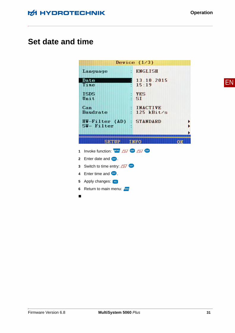
Set date and time
1 Invoke function:
2 Enter date and .
3 Switch to time entry:
4 Enter time and .
5 Apply changes:
6 Return to main menu:

Firmware Version 6.8 MultiSystem 5060 Plus 32
Operation
EN
Connect sensors
1 Switch the instrument off.
2 Connect the desired sensors to the inputs.
See Chapter Connections on page 15.
3 Switch the device on.

Firmware Version 6.8 MultiSystem 5060 Plus 33
Operation
EN
Enter sensor parameters
1 Open Channel menu:
2 Highlight channel:
3 Start programming:
4 Highlight menu item:
5 Select function:
6 Highlight setting: ,or enter value, e.g. 12.5
7 Confirm setting or value:
8 Apply changes:
If you have connected ISDS sensors, the sensor parameters will be detected automatically when the instrument is switched on. Then you can skip this section.
If you have connected sensors without ISDS function, you will have to program the sensor parameters manually. You find the required information e.g. on the type plate or the calibration certificate of your sensor.

Firmware Version 6.8 MultiSystem 5060 Plus 34
Operation
EN
Available measurands The instrument is able to process ~ 40 different measurands including pres-sure, volume flow rate, temperature and rotational speed. Make sure you select the measurand and unit corresponding to the sensor.
Index variable If several channels are programmed with the same measurand, these will be automatically indexed consecutively. The automatic indexing can be disabled in the device menu to allow manual assignment of index numbers.
Name You can assign an individual name to each channel.
Signal types Select between 0/20 mA, 4/20 mA, 0/10 V, ± 10 V, 0.5/4.5 V, 1/5 V, 2/10 V.
Measuring range Enter the beginning and end of the measuring range. Confirm these two en-tries with .
Zero point Press F4 to execute the automatic zero point equalization. A possible zero point deviation will be compensated by the software.
Linearisation If a calibration table is available for the connected sensor, you can enter it here, after selecting YES at the menu item Linearisation.
Please observe the additional information in chapter Chapter Linearisa-tion table on page 136.
Help Press to open a context-sensitive help screen with information to channel specifications and pin assignment.
Load Press to load sensor parameters from the sensor data base.
Save Press to save the current sensor parameters in the sensor database.

Firmware Version 6.8 MultiSystem 5060 Plus 35
Operation
EN
Record measuring data
Data are collected in series of measurements. These can be configured in the memory menu.
1 Invoke function:
2 Make selection:
3 Confirm selection:
4 Apply changes:
5 Return to measured values display:

Firmware Version 6.8 MultiSystem 5060 Plus 36
Operation
EN
Channels Activate the channels where the measurement data is to be recorded.
Storing time Enter how long the measurement data is to be recorded. Select the desired time unit.
1. Scanning rate Define how often the measurement data is to be recorded. Select the desired time unit.
2. Scanning rate If you want to record certain channels with a reduced scanning rate (e.g. tem-perature), you can enter a multiple of the 1st scanning rate here. You can then assign the 2nd scanning rate to the desired channels in the channel se-lection list.
Trigger 1 A trigger is a condition that has to happen to make the storing of measurement data start or stop. In this case, no trigger is defined.
Please see section Chapter Configure digital signal output (C10) on page 51 for further information on how to use the trigger function.
Storing time and scanning rate define, how often and how long measurement data is to be stored. Be aware that if you store too much measurement data, the later evaluation and presentation will become more difficult.

Firmware Version 6.8 MultiSystem 5060 Plus 37
Operation
EN
Connect a PC and transfer measurement data
1 Switch on measuring instrument and PC.
2 Plug the supplied USB cable into the connector on the side of the measur-ing instrument.
3 Plug the USB cable into an available USB port on your PC.
4 Wait until the measuring instrument has been detected by the PC.
5 Perform the data transfer as described in the software documentation.
You have to install the software HYDROcom on your PC, before you can transfer measurement data to your PC.

Firmware Version 6.8 MultiSystem 5060 Plus 38
Operation
EN
Delete measuring data
In the example shown, the series of measurement 002 and 003 has been se-lected for deletion already, an * is displayed next to the measurement. If you press , the names of the measurement files will be displayed; pressing will provide you more information about the highlighted measurement.
1 Invoke function:
2 Delete single or all measurements:
3 Select measurement(s) (only for Delete Single):
4 Start deletion (only for Delete Single):
5 Confirm deletion:
6 Return to main menu:

Firmware Version 6.8 MultiSystem 5060 Plus 39
Operation
EN
Print measuring data
1 Open presentation menu:
2 Select measurement:
3 Select presentation type (output):
4 Select channels and presentation:
5 Select size: ;
• For size, select CLIPPING
• Enter time limits From and To.
6 Start printing:
Before you can print measurement data, a printer must be connected and set up.
Firmware Version 6.8 MultiSystem 5060 Plus 40
Operation
EN
Reset device
1 Switch device off:
2 Switch device on:
3 Wait until the beginning of the initialisation is displayed and then press:
4 Confirm resetting:
The selection list of the available operation languages will be displayed, from where you may select the desired ones. Then the device will be reset and restarted.
All user-defined parameters and settings (channels, display, memory, etc.) will be deleted by resetting the device. All data on the SD card remain unaffected (meas-ured values, sensor and CAN database, projects, test runs, databases from test runs, etc.).

Firmware Version 6.8 MultiSystem 5060 Plus 41
Operating software
EN
Operating software
The operating software of the MultiSystem 5060 Plus will be presented and explained chronologically on the following pages.
Measured values display
After switching on and initialisation, the currently measured values are dis-played. You can select in the Display menu, which channels shall be displayed here.
You can choose from two different measured values displays:
• Measured values together with minimum and maximum values (MinMax)
• Measured values with their units

Firmware Version 6.8 MultiSystem 5060 Plus 42
Operating software
EN
Measured values with MinMax
To the right of each measured value display, the measured minimum value (upper left) and maximum value (bottom right) are displayed.
MEAS.V switches to display of measured values with their units
DELETE resets the displayed minimum and maximum values
HOLD "freezes" the measured values display; new measured values won't be displayed; the word "HOLD" flashes; press again to display the current values.

Firmware Version 6.8 MultiSystem 5060 Plus 43
Operating software
EN
Measured values with their units
The units are displayed to the right of each measured value.
MINMAX switches to display of measured values with MinMax
HOLD "freezes" the measured values display; new measured values won't be displayed; the word "HOLD" flashes; press again to display the current values.
After pressing HOLD, you can print out the contents of the screen by pressing PRINT. A printer must be connected and available to use this func-tion.

Firmware Version 6.8 MultiSystem 5060 Plus 44
Operating software
EN
Menu
For the following explanations, it is assumed that the Menu is displayed.
MENU opens the Menu; you can operate all functions of the MultiSystem 5060 Plus from here.

Firmware Version 6.8 MultiSystem 5060 Plus 45
Operating software
EN
Available submenus
Highlight the desired menu with and press .
Channels Configuration of input and special channels
Display Various settings of the measured values display
Memory Configuration of several memory parameters
Device Basic configurations of the device
Projects Function for managing device configurations
Specialapplications
includes functions for the operation of optional features (e.g. CAN, automatic test procedures, particle counter)
Available functions
START starts the recording of measurement data; the configurations from the memory menu (channel selection, storing time, scanning rate, a.s.o.) are applied
SHOW opens the Presentation Menu for display and printing of the saved measurements
DELETE opens the Delete Menu for deleting individual measurements or all measurements
USTICK opens the submenu with the USB stick functions

Firmware Version 6.8 MultiSystem 5060 Plus 46
Operating software
EN
Start a recording
After initiating the recording with , a dialogue will be displayed, where the defined recording parameters (selected channels, recording time, trigger, etc.) are shown. The device proposes the current date and time as name of the measurement series.
Meas. series x Name of the measurement series; press to overwrite the proposal
Filename Here you may enter a (different) name for the measurement series data file
Mode Choose from three options:
• STANDARD
The defined recording and parameters will be applied to execute one sin-gle recording
• CYCLIC
The defined recording parameters will be applied to execute a recording; then the recording will be repeated until the key C-STOP is pressed
• SINGLE
The current value of each selected channel will be recorded when key is pressed
If you want to assign a note to the recording, press and enter the desired text. Start the recording with .

Firmware Version 6.8 MultiSystem 5060 Plus 47
Operating software
EN
Open presentation menu
See Presentation function on page 116.
Open delete menu
See Delete series function on page 129.
Use an USB stick
See USB stick menu function on page 130.

Firmware Version 6.8 MultiSystem 5060 Plus 48
Operating software
EN
Channels submenu
There are 24 channels available:
• C1 ... C8
Measuring channels; sensor connectors at the rearside of the device
• C9
Trigger input
• C10
Trigger output
• C11 ... C24
Special channels
Press to highlight a channel.
Press to switch between the pages of the submenu. The second page contains channels 13 to 24.

Firmware Version 6.8 MultiSystem 5060 Plus 49
Operating software
EN
Configure measuring channels (C1 ... C8)
You may configure several parameters for each measuring channel:
Measurand Selection of measurand and unit; select between 18 different measurands and up to five units per measurand
Index Variable If manual channel numeration is activated in the setup menu (see section on page Dialogue Setup (1/2) on page 82), you can enter the index number of the channel here; if automatic channel numeration is activated, this function will not be displayed
Name You may enter an individual name for each channel
The name will now be shown in the tile display of the measured values display.
See Configure tile presentation on page 59.
Measuring channels must only be configured if you use sensors without ISDS capabilities.

Firmware Version 6.8 MultiSystem 5060 Plus 50
Operating software
EN
Signal type Sensor-specific
Select between (0/20 mA), (4/20 mA), (0/10 V), (±10 V), (0.5/4.5 V), (1/5 V) and (2/10 V)
The correct signal type is given on the type plate of the sensor or in its docu-mentation; for frequency sensors (channels C7 and C8), select between with direction (w.D.) and no direction (n.D) Direction detection
Meas. range Enter the smallest and largest expected measured value (for analogue sen-sors, only)
Calibration value Enter the factor for the calculation of the measuring value from the frequency signal (for frequency sensors, only)
Zero point Manual zero point alignment of the sensor (see Do zero point equalisation on page 51)
Linearisation If available, you may enter or select a linearisation table for the connected sen-sor. This may increase measuring accuracy.
You can find more information in Chapter Linearisation table on page 136.
Additional functionsHELP opens a help screen with additional information
LOAD loads stored sensor parameters from the database
SAVE stores the current sensor parameters in the database
OK saves the channel settings and leaves the submenu
Firmware Version 6.8 MultiSystem 5060 Plus 51
Operating software
EN
Do zero point equalisation
After selecting the function ( ) a display will appear for confirming the zero point alignment.
Press to start the zero point alignment. This process is carried out fully au-tomatically, the determined value will be displayed after a few seconds.
Configure digital signal input (C9)
You can only assign one name to the digital signal input. Please observe the technical data (Technical data on page 24) for permitted input signals.
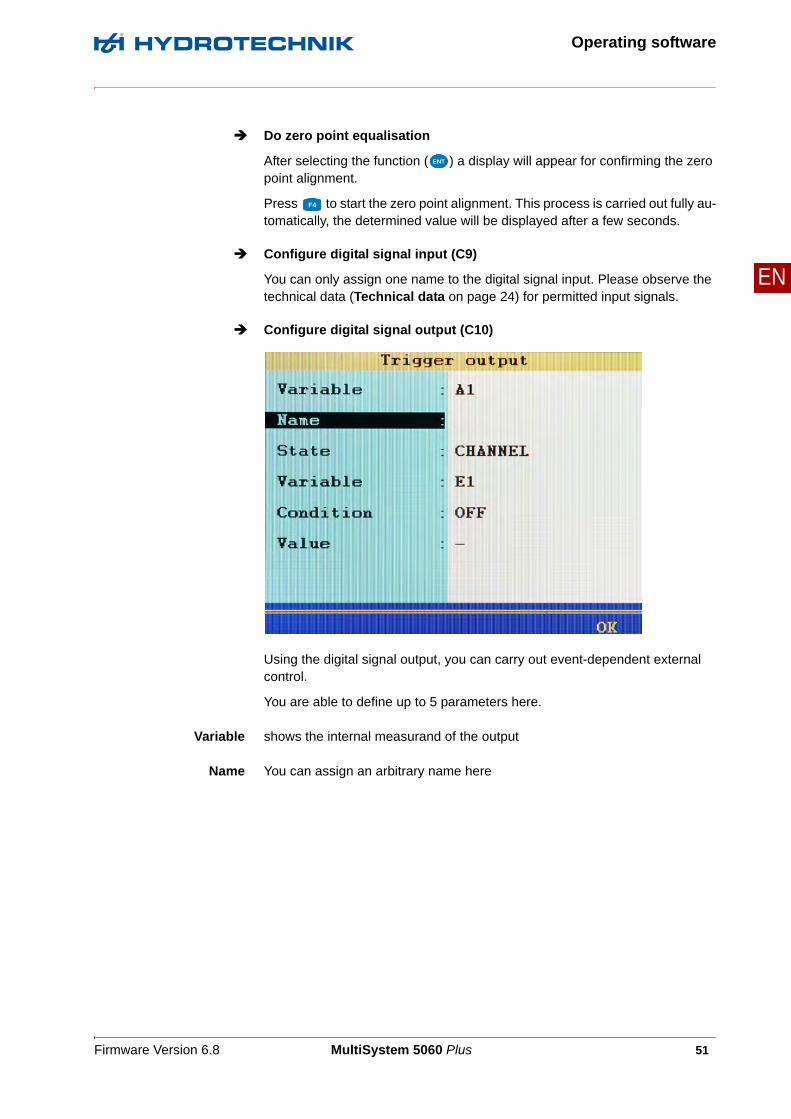
Configure digital signal output (C10)
Using the digital signal output, you can carry out event-dependent external control.
You are able to define up to 5 parameters here.
Variable shows the internal measurand of the output
Name You can assign an arbitrary name here

Firmware Version 6.8 MultiSystem 5060 Plus 52
Operating software
EN
State Source of the triggering event;
• INACTIVE
Trigger off
• CHANNEL
Channel is monitored for the occurrence of the triggering event,
• SP-TRIG
Trigger is set if trigger was detected during saving.
This allows multiple measuring instruments to be synchronised:
– Master: Saving of triggering event X (e.g. p1>200) – trigger output: SP_TRIG;
– Slaves: Saving of triggering event E1
• MANUAL: the trigger output is switched manually by pressing a key
Variable Selection of which channel should switch the trigger output.
You can also select Vbat (battery voltage) or Vnet (mains power voltage) to switch the trigger output if the voltage falls below a defined value.
Condition for trigger input OFF/ON
for measurement channels GREATER THAN/LESS THAN
Value for measuring channels, e.g. 200

Firmware Version 6.8 MultiSystem 5060 Plus 53
Operating software
EN
Configure special channels (C11 ... 24)
The special channels are used to mathematically combine the measured val-ues of several sensors and do calculations with it, or to be configured as input channels for the CAN bus or the RS232 interface.
Calculation Choose between the different occupations of the channel (see further below)
See Possible assignments of the special channels on page 55.
Variable is entered automatically when using pre-programmed formulas and cannot be edited;
for individual formulas and assignment with CAN or Multimeter you may define the variable here that is provided on this channel
Index Variable If numeration chn. is set in the setup menu (see Dialogue Setup (1/2) on page 82), you may enter the index number of the channel here

Firmware Version 6.8 MultiSystem 5060 Plus 54
Operating software
EN
Unit is entered automatically when using pre-programmed formulas and cannot be edited;
define the unit for channels with individual formulas and assignment with CAN or Multimeter
Name You can assign an arbitrary name here
Align.Diff This functions automatically determines the measured value difference be-tween the selected channels and use it as offset
Formula Enter the desired formula here (only displayed if Calculation is set to FOR-MULA, see Possible assignments of the special channels on page 55)
Additional functionsLOAD loads stored channel parameters from the database
SAVE stores the current channel parameters in the database
OK saves the channel settings and leaves the submenu
Firmware Version 6.8 MultiSystem 5060 Plus 55
Operating software
EN
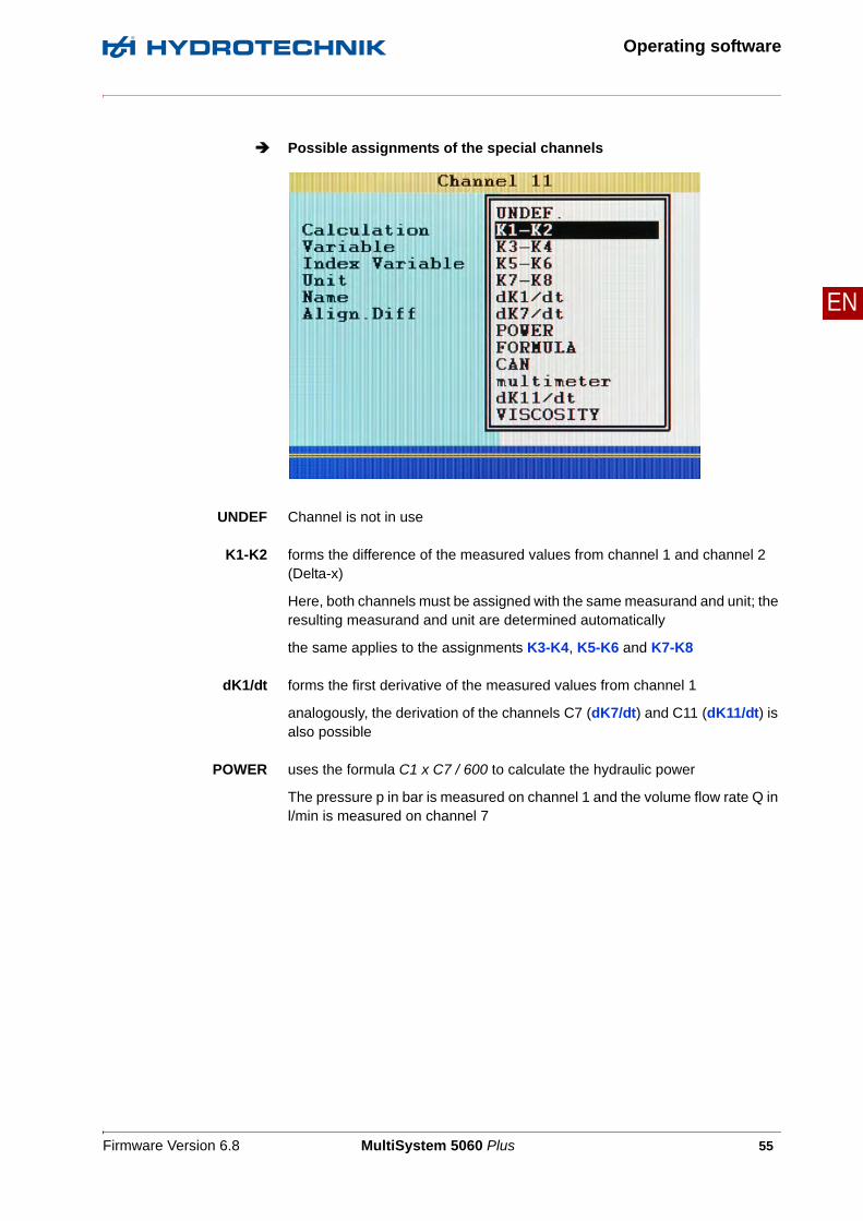
Possible assignments of the special channels
UNDEF Channel is not in use
K1-K2 forms the difference of the measured values from channel 1 and channel 2 (Delta-x)
Here, both channels must be assigned with the same measurand and unit; the resulting measurand and unit are determined automatically
the same applies to the assignments K3-K4, K5-K6 and K7-K8
dK1/dt forms the first derivative of the measured values from channel 1
analogously, the derivation of the channels C7 (dK7/dt) and C11 (dK11/dt) is also possible
POWER uses the formula C1 x C7 / 600 to calculate the hydraulic power
The pressure p in bar is measured on channel 1 and the volume flow rate Q in l/min is measured on channel 7

Firmware Version 6.8 MultiSystem 5060 Plus 56
Operating software
EN
FORMULA Input of an individual formula
See Calculations with formulas on page 56.
CAN Observe the information in chapter Chapter Define CAN channel on page 138
multimeter If you have connected an external measuring instrument to the RS232 inter-face, you can assign its measurements to a channel;
you can find additional information under Connection of external meas-uring devices on page 156.
Calculations with formulas
You may perform arbitrary calculations and use the values from all channels in your formula. You may use all basic arithmetic operations. Do not enter spaces. If you need additional mathematic functions, you may create the re-quired calculated channels during the data evaluation with HYDROcom

Firmware Version 6.8 MultiSystem 5060 Plus 57
Operating software
EN
Example of a formula C13/600*(C1-C5)
Press the key once to enter a C (= channel), resp. press twice to enter a 5. You can only enter numbers with the remaining number keys; special char-acters with .
Confirm the input with . The measuring system does not check the entered formula for plausibility.
Example of aconsumption
measurement in [l/min]
Some measuring channels are absolutely required for this example. They are printed in bold letters:
• Channel 7: Measurement of volume V1 in litre (l)
• Channel 8: Measurement of volume V2 in litre (l)
• Channel 11: Calculation C7 - C8 = dV1 in litre (l)
• Channel 12: Calculation dC11/dt = Q1 in litre per second (l/s)
• Channel 13: Calculation C12 * 60 = Q2 in litre per minute (l/min)
Values from special channels can only be used if the ordinal number of the used channel is lower.Possible formula on channel 14: C12+C1, impossible formula on C14: C15+C1.

Firmware Version 6.8 MultiSystem 5060 Plus 58
Operating software
EN
Display submenu
In the Display menu, you can select which channels you would like to have dis-played in the measured values display. Basic configurations are also possible.
Channels After opening this function, you can select the channels which are to be dis-played in the measured values display.
All channels that have YES behind them will be displayed
Highlight a channel and use to switch between YES and NO
Display rate The display defines the refresh rate of the measured values display
Select one of the five possible values
Contrast specifies the brightness value of the display
Select 10, 50 or 100 %

Firmware Version 6.8 MultiSystem 5060 Plus 59
Operating software
EN
Presentation You can choose between the following options here:
• TEXT: (The measured values are shown numerically
• Graphical presentation
– GRAPHIC Y = F(T)
– GRAPHIC Y = F(X)
See Configure graphical presentation on page 61.
• Tile presentation
– 4 panels
– 9 panels
– 12 panels
See Configure tile presentation on page 59.
Configure tile presentation
Here you have three possibilities for the tile presentation:
• 4 panels
Shows 4 tiles in the measured values display.
• 9 panels
Shows 9 tiles in the measured values display.
• 12 panels
Shows 12 tiles in the measured values display.

Firmware Version 6.8 MultiSystem 5060 Plus 60
Operating software
EN
The measured values are shown in tiles. Measurands, index and units are dis-played under each measured value.
The name of the measurement channel is displayed above the measured val-ue. The name of the measurement channel must be configured in the Channels submenu.
See Configure measuring channels (C1 ... C8) on page 49.
If there are more channels selected for display than there are tiles shown, this will be displayed to the right in the toolbar: (current page/total pages).
Switch to the next page of tiles with .
HOLD "freezes" the display; new measured values won't be dis-played; the word HOLD flashes; press again to display the current values.
After pressing HOLD, you can print out the contents of the screen by pressing PRINT. A printer must be connected and available to use this func-tion.

Firmware Version 6.8 MultiSystem 5060 Plus 61
Operating software
EN
Configure graphical presentation
You have two possibilities for configuring the graphical presentation:
• Y = F(T)
Presentation of the channels as a function of time
The additional options Scaling and Symbol/Colours are displayed here
• Y = F(X)
Presentation of the channels as a function of an arbitrary channel
The additional options X-axis, Scaling and Symbol/Colours are dis-played here.
X-axis Select the channel on which the function for the graphical presentation is to be based.
Scaling Select the measurement range of the channel which is to be displayed in the graphical presentation.
See Display scaling dialogue on page 62.
Symbol/Color You can assign symbols and colours to the channels here.
See Graphic menu dialogue on page 63.

Firmware Version 6.8 MultiSystem 5060 Plus 62
Operating software
EN
Display scaling dialogue
You have defined the measuring range of a channel in the Channels submenu.
See Configure measuring channels (C1 ... C8) on page 49.
If desired you can now define a part of the measuring range to be displayed in the graphical presentation.
Press to do an automatic scaling for the selected channel, i.e., the device uses the measuring range defined in the channel parameters for the display scaling.
With , the respective measuring range entered for all channels will be used.
1 Select the desired channel.
2 Enter lower limit of display range – .
3 Enter upper limit of display range – .
4 Repeat 1 to 3 for all desired channels.
5 Confirm entries – .

Firmware Version 6.8 MultiSystem 5060 Plus 63
Operating software
EN
Graphic menu dialogue
First, for the Symbols function, select:
• YES: Symbols and colours are used
• NO: Only colours are used
You can assign symbols and colours to the channels after making this basic selection:
Press AUTO to assign the standard settings to all channels. When a chan-nel is highlighted, you can press or to open the selection lists ‘Symbols’ or ‘Colours’ to speed up the selection.
1 Highlight a channel – .
2 Select a symbol – .
(only for activated symbols)
3 Select a colour – .
4 Repeat steps 1 to 3 for all desired channels.
5 Confirm entries – .

Firmware Version 6.8 MultiSystem 5060 Plus 64
Operating software
EN
Memory submenu
You can select channels in the memory menu that you want to store in series of measurements and set basic memory options.
Channels Select the channels that shall be stored in series of measurements; all chan-nels will be displayed after opening the function; toggle between YES (channel will be stored) and NO (channel will not be stored).
Storing time Storing duration; enter time value – highlight time interval unit
1. Scanning rate Time distance between two measurements in a series; enter time value – highlight time unit

Firmware Version 6.8 MultiSystem 5060 Plus 65
Operating software
EN
2. Scanning rate If you want to record certain channels with a reduced scanning rate (e.g. tem-perature measurement), you can enter a multiple of the first scanning rate here; this second scanning rate can be assigned one or multiple channels (a factor of 500 results for the first scanning rate = 1 ms, a second scanning rate of 500 ms = 0.5 seconds)
Consider the storing capacity of the measuring device when setting these options. The amount of data will increase if you configure more channels, a longer storing time, and a shorter scanning time. Large amounts of data may make evaluation and estimation of measuring results more difficult. Use the 2nd scanning rate to reduce the amount of data at those channels where you expect less dynamic changes.
Scanning rates < 1 ms are selectable, when the measuring instrument works in the dynamic mode (hardware filter) and the software filters are switched off. Oth-erwise this option is blocked. At scanning rates < 100 ms, the hardware filters should not be set to dynamic to avoid malfunctions.
Firmware Version 6.8 MultiSystem 5060 Plus 66
Operating software
EN
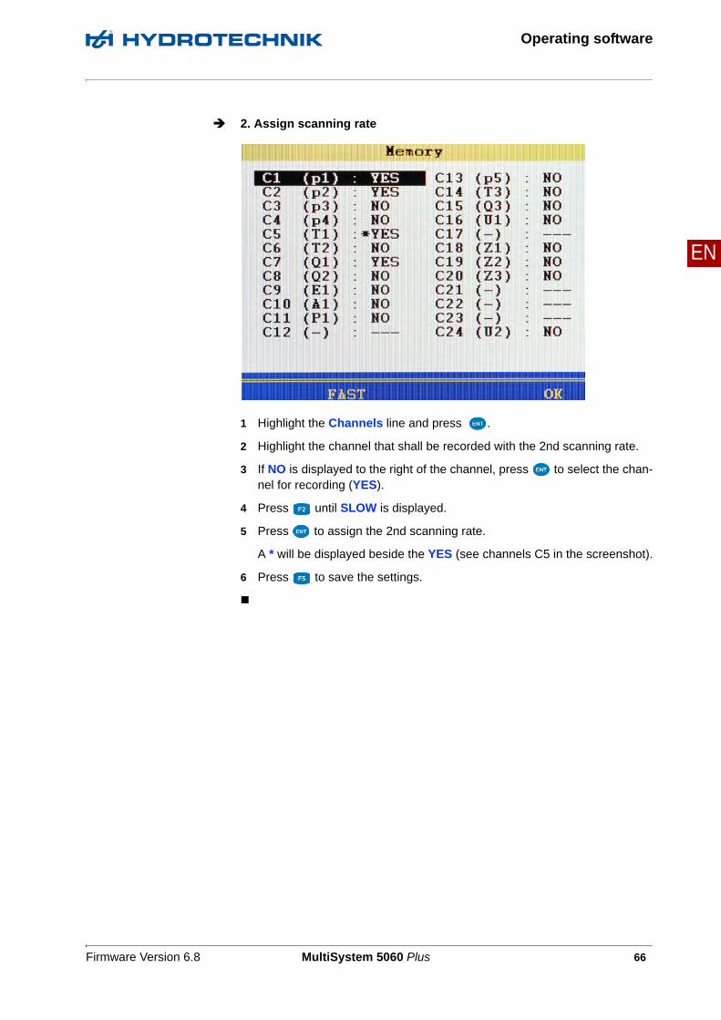
2. Assign scanning rate
1 Highlight the Channels line and press .
2 Highlight the channel that shall be recorded with the 2nd scanning rate.
3 If NO is displayed to the right of the channel, press to select the chan-nel for recording (YES).
4 Press until SLOW is displayed.
5 Press to assign the 2nd scanning rate.
A * will be displayed beside the YES (see channels C5 in the screenshot).
6 Press to save the settings.
Firmware Version 6.8 MultiSystem 5060 Plus 67
Operating software
EN
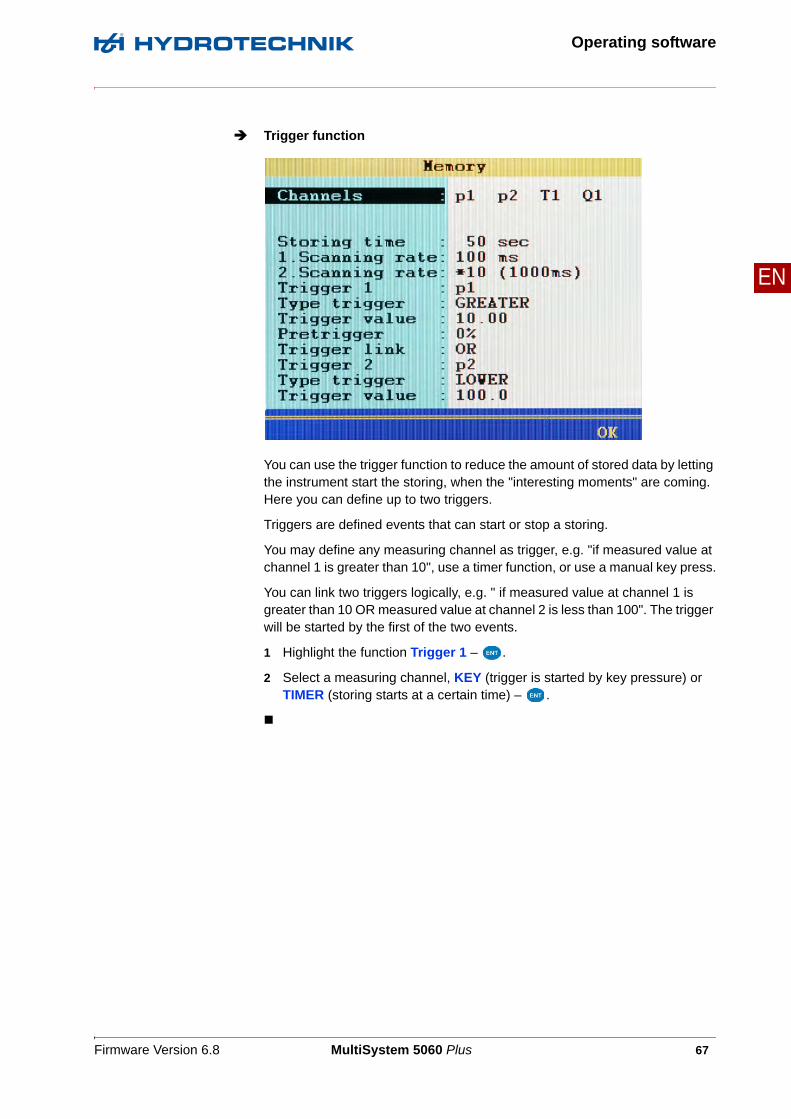
Trigger function
You can use the trigger function to reduce the amount of stored data by letting the instrument start the storing, when the "interesting moments" are coming. Here you can define up to two triggers.
Triggers are defined events that can start or stop a storing.
You may define any measuring channel as trigger, e.g. "if measured value at channel 1 is greater than 10", use a timer function, or use a manual key press.
You can link two triggers logically, e.g. " if measured value at channel 1 is greater than 10 OR measured value at channel 2 is less than 100". The trigger will be started by the first of the two events.
1 Highlight the function Trigger 1 – .
2 Select a measuring channel, KEY (trigger is started by key pressure) or TIMER (storing starts at a certain time) – .

Firmware Version 6.8 MultiSystem 5060 Plus 68
Operating software
EN
Definition of a measuring channel as trigger
1 Open the function Type trigger and highlight the desired option. Then press .
• GREATER: Actuation when trigger value is exceeded
• LOWER: Actuation when trigger value is fallen below
• RISING: Actuation when trigger value is fallen below by more than 5 % and then exceeded, "rising edge"
• FALLING: Actuation when trigger value is exceeded by more than 5 % and then fallen below, "falling edge"
2 Enter trigger value .
Definition of a trigger time
1 Enter the date of the trigger time – .
2 Enter the time of day of the trigger time – .
Press (SET) to enter the current system values for trigger date and time.
Define pretrigger
When a pretrigger is defined, the storing starts before the trigger event has happened. The percentage defined as pretrigger is used to store measured values before the trigger event.
1 Select a percent value as pretrigger – .

Firmware Version 6.8 MultiSystem 5060 Plus 69
Operating software
EN
Trigger link
You can link Trigger 1 with a second trigger:
1 Highlight an option of the Trigger link function and then press .
• NONE: Trigger 2 is not used
• AND: Trigger 1 and Trigger 2 must occur
• OR: Trigger 1 or Trigger 2 must occur
• START/STOP: Trigger 1 starts the storing, Trigger 2 stops it
2 Define trigger type and trigger value of Trigger 2.
See Definition of a measuring channel as trigger on page 68.

Firmware Version 6.8 MultiSystem 5060 Plus 70
Operating software
EN
Example of a triggerrecording
A 2-minute recording is to be started when the measured value for p2 falls be-low 50 bar and temperature T1 rises above 30 °C. The recording is to start 60 seconds before the trigger incident.
Required programming:
Storing time 2 min.
Trigger 1 p2
Type trigger LOWER
Trigger value 50.00
Pretrigger 50 %
Trigger link AND
Trigger 2 T1
Type trigger GREATER
Trigger value 30.00

Firmware Version 6.8 MultiSystem 5060 Plus 71
Operating software
EN
Device submenu
Configuration of the instrument is done with the Device menu:
Language Operating language
Date Current date
Time Current time
ISDS Automatic sensor detection
Unit Select the unit system
CAN Enable/disable CAN bus
Baud rate Set transmission speed for CAN data
HW filter (AD) Hardware filter selection for each measuring channel
SW filter Software filter definition for each measuring channel
Press to switch to the 2nd page of the submenu.

Firmware Version 6.8 MultiSystem 5060 Plus 72
Operating software
EN
Company Enter the company name for the printouts
Printer Printer selection
Format Selection of the print format
Keyboard Selection between STANDARD and COMFORT
Service Selection between overview and detail
RS 232 Select the speed of the RS 232 interface
Press to switch to the 3rd page of the submenu.
Ethernetmodule Select between YES and NO.
Connect the Ethernet module to the measuring instrument and select YES.
IP Enter the IP address in the Ethernet network
Port This is preassigned and displayed for information purposes only
Password Enter the password for logging onto the network
ToolbarSETUP Information for error analysis (for experienced technicians
only)
INFO Information on the software of the measuring instrument
OK Confirm and save changes

Firmware Version 6.8 MultiSystem 5060 Plus 73
Operating software
EN
Select operating language
1 Invoke function:
2 Select language:
3 Confirm changes and leave function:
Enter date
1 Invoke function:
2 Enter day and .
3 Enter month and .
4 Enter year and .
5 Confirm changes and leave function:
Enter time
1 Invoke function:
2 Enter hour and .
3 Enter minutes and .
4 Confirm changes and leave function:

Firmware Version 6.8 MultiSystem 5060 Plus 74
Operating software
EN
ISDS configuration
When using ISDS sensors, the sensor parameters will be stored automatically after connecting the sensor and switching on the instrument. Enable this func-tionality here and select the unit if you want to use ISDS sensors.
1 Invoke function:
2 Enable functionality YES:
3 Switch to the enter the unit:
4 Select desired unit:
5 Confirm changes and leave function:
The new unit system will be used the next time the instrument is switched on again.
CAN configuration
You can define a calculation channel as CAN channel (see Chapter Define CAN channel on page 138). To enable this you have to activate the CAN bus here and set the data transmission rate.
1 Invoke function:
2 Activate CAN bus ACTIVE:
3 Switch to select the baud rate:
4 Select desired baud rate:
5 Confirm changes and leave function:

Firmware Version 6.8 MultiSystem 5060 Plus 75
Operating software
EN
Set hardware filter
You can execute several special measurements by applying filters.
Filter- Mode Each channel can be defined individually (INDIVIDUAL)
You can set hardware filters so that measurements of peak pressures up to 10 kHz can be executed. This causes a high CPU load, calculations in the instru-ment, presentation of graphs and transmission of data to a PC will slow down.
The filtering of the measuring values results from the sum of all active hardware and software filters. You should disable all filters if you want to measure with very short measuring rates.

Firmware Version 6.8 MultiSystem 5060 Plus 76
Operating software
EN
Filter Choose from three hardware filters:
• DYNAMIC
No hardware filter; peak pressure measurements up to 10 kHz possible on C1 and C2 (only if software filters are switched off), on C3 to C6, up to 2 kHz possible
• STANDARD
A 5 kHz hardware filter is applied to C1 and C2; peak pressure measure-ment up to 2 kHz possible on C1 to C6
• DAMPED
A 50 Hz hardware filter is applied to C1 to C6; peak pressures are sup-pressed; ideal for static measurements or slow processes
This is how to set the desired hardware filter:
1 Invoke function:
2 Select filter mode:
• For INDIVIDUAL, highlight channel:
• Select filter mode for the channel:
3 Confirm changes and leave function:

Firmware Version 6.8 MultiSystem 5060 Plus 77
Operating software
EN
Set software filter
Filter The analogue inputs are scanned with 0.1 ms (10 kHz). By using the software filter, you can equalise the measured values by averaging 10 to 160 measured values. Frequencies are measured down to 0.25 Hz. This frequency is first de-tected and displayed after a period duration of 4 s.
Min.Frequency Frequencies that are less than the value Min. Frequency are displayed as zero.
The value Min.Frequency can be set to 0.25, 1, 10 or 100 Hz.
For a minimum frequency of 1 Hz, the decrease to zero during the recording is shown with a delay of 1 s. For a minimum frequency of 0.25 Hz, the delay is 4 s.
The filtering of the measuring values results from the sum of all active hardware and software filters. You should disable all filters if you want to measure with very short measuring rates.

Firmware Version 6.8 MultiSystem 5060 Plus 78
Operating software
EN
Gate Time Frequency inputs are equalised by the gate time. The longer the gate time, the slower the measuring values will change, since a new value is only recorded after a delay. In the mean time, the measuring values remain constant. The re-sult is a signal smoothing.
This is how to set the desired software filter:
1 Invoke function:
2 Select AD channel:
3 Select equalisation filter:
4 Repeat steps 2 to 3 for all desired AD channels.
5 Select Gate Time f1 (for measuring channel C7):
6 Enter desired gate time (x 10 ms) and .
7 Select Min.Frequency (for measuring channel C7):
8 Select desired frequency:
9 Repeat 5 to 8 for Gate Time f2 and second minimum frequency (for measuring channel C8).
10 Confirm changes and leave function:
Firmware Version 6.8 MultiSystem 5060 Plus 79
Operating software
EN
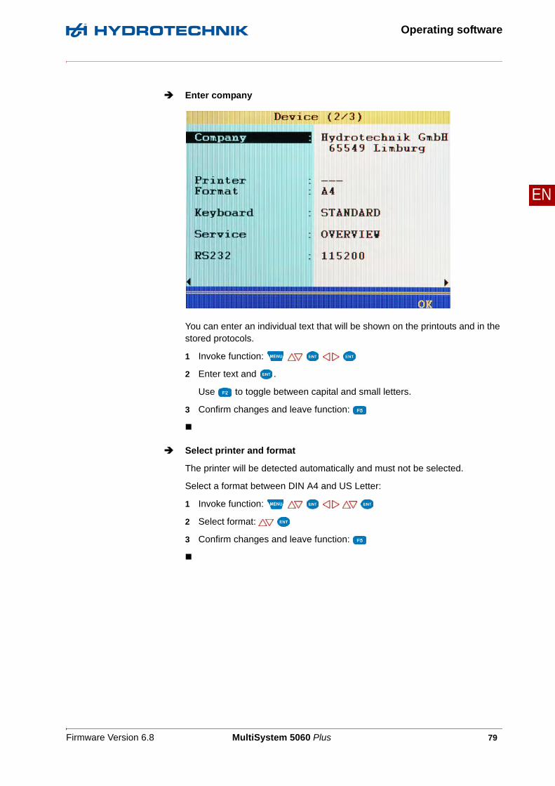
Enter company
You can enter an individual text that will be shown on the printouts and in the stored protocols.
1 Invoke function:
2 Enter text and .
Use to toggle between capital and small letters.
3 Confirm changes and leave function:
Select printer and format
The printer will be detected automatically and must not be selected.
Select a format between DIN A4 and US Letter:
1 Invoke function:
2 Select format:
3 Confirm changes and leave function:

Firmware Version 6.8 MultiSystem 5060 Plus 80
Operating software
EN
Select keyboard
Here you can select whether the short-cut method for the (COMFORT) menu operation is to be activated. You no longer need to highlight functions with the arrow keys and select them with Enter, but can simply press the assigned number key. E.g. if you press 4 in the main menu, the device menu will be opened instantly.
1 Invoke function:
2 Select keyboard function:
3 Confirm changes and leave function:
Select Service
Here you can set the amount of information that will be included in the service report of the instrument.
• OVERVIEW includes the most important settings and parameters
• DETAIL includes additional information for service cases
1 Invoke function:
2 Select report type:
3 Confirm changes and leave function:
While the item Service is highlighted, you can press to print the ser-vice information.
Set RS232 interface speed
If you want to use the RS232 interface (e.g. to connect an external measuring device, Multimeter), you can set the data transmission speed here:
1 Invoke function:
2 Select speed:
3 Confirm changes and leave function:

Firmware Version 6.8 MultiSystem 5060 Plus 81
Operating software
EN
Setting up Ethernet functionality
If you want to use an Ethernet network module connected to the RS232 port, you can configure it here:
These options can be set:
Ethernetmodule Select whether an Ethernet module is connected (YES)
IP Enter the IP address that the MultiSystem 5060 Plus is to have in the Ether-net network
Port This is preassigned and displayed for information purposes only
Password Enter the password for the Ethernet network, if a password is required
1 Display the Ethernet options:
2 Select the desired option:
3 Select the desired setting or enter the required information.
4 Confirm the setting/entry:
5 Confirm changes and leave function:

Firmware Version 6.8 MultiSystem 5060 Plus 82
Operating software
EN
Dialogue Setup (1/2)
You can carry out a variety of basic functions in the Setup menu:
1 Open setup:
2 Select function:
3 End selection:
4 Leave function:
Note
Loss of data possibleThe internal data carrier can be formatted in the Setup menu.This will delete permanently delete all contained data and cannot be undone.

Firmware Version 6.8 MultiSystem 5060 Plus 83
Operating software
EN
Use USB stick for firmware update
If an USB stick had been detected at the instrument, its name is displayed in the first line. Press to read the data from the USB stick.
Then you can then start the firmware update:
1 Highlight the desired firmware version:
2 Confirm the desired firmware version:
3 Start the firmware update:
Observe the additional information in chapter Chapter Firmware update using the USB Stick on page 150
Select storage medium
If an USB stick had been detected at the instrument, you may select between the internal SD card and the stick as storage medium. Highlight the item Stor-age medium and press to toggle between the two media.
Format SD card
When the menu item Storage medium is highlighted and the SD card is se-lected as storage medium, you can press to format the internal SD card. This will delete all data contained on the card (e.g. measurement data). The formatting cannot be undone.
When recording measured values to the USB stick directly, it is not possible to use triggers and only a minimum scanning rate of 100 ms is supported.

Firmware Version 6.8 MultiSystem 5060 Plus 84
Operating software
EN
PowerCAN function
Use this function to switch the power supply of connected CAN sensors ON and OFF. Highlight the function with and press to toggle between ON and OFF.
Function CANopen Device
Here you can trigger the start command into the CAN bus that requests the connected sensors and adaptor boxes to send data. Highlight the function and then press .
Function CAN Tx Msg
This function is now in the Special applications submenu. See Chapter Load valve on page 105.
Function Numeration chn.
As a standard, the MS 5060 Plus numerates all channels with a letter and an index number. If three pressure sensors are connected, the channels will be numerated as p1, p2 and p3 automatically. If you now connect, e.g. a temper-ature sensor instead of p1, this channel will become t1. The two other channels will be renamed, p2 will become p1 and p3 will become p2.
By changing the Numeration chn. from AUTO to MANUAL, you can assign fixed index numbers to the channels (see Chapter Configure measuring channels (C1 ... C8) on page 49). These will remain even after the channel assignment has changed. In the example shown above, the three channels would be numerated as t1, p2 and p3.
Highlight the function with and press to toggle between AUTO and MANUAL.
The following functions are present for compatibility reasons. Please use the cor-responding functions in the Special applications submenu.

Firmware Version 6.8 MultiSystem 5060 Plus 85
Operating software
EN
Locking menus
Assignment of the function keys:
After opening the submenu, you first have to define the release code:
1 Start release code definition:
2 Enter release code; observe the assignment of the function keys.
3 Confirm release code:
4 Highlight displayed menus:
5 Press to toggle between – (menu released) and LOCKED. When try-ing to do changes in a locked menu, a corresponding warning will be displayed after pressing .
6 Confirm changes and leave function:
HELP Opens a help screen for the alphanumeric entry
abcd Toggles between the entry of capital and small letters
<-- Deletes the last entered digit
INSERT Inserts a digit in front of the flashing digit
DELETE Deletes all digits of the release code

Firmware Version 6.8 MultiSystem 5060 Plus 86
Operating software
EN
Dialogue Setup (2/2) - Calibr. interval
The measuring instrument was calibrated before it was shipped by the manu-facturer. The calibration interval is the period of time after which the measuring instrument is to be re-calibrated by the manufacturer.
You can only define the calibration interval once. After that, it can no longer be changed.
The measuring instrument is also ready for use if no calibration interval is set.
Reminder If a calibration interval is exceeded, the measuring instrument displays the message Calibrate after switch-on:
You can suppress the message for the selected number of days.
Time interval 6, 12, 18, 24, 30 or 36 months can be set as the calibration interval.
Calibr. date Displays the date of the last calibration.
The calibration interval cannot be changed. Do not set a calibration interval if you are unsure which interval is right for you.

Firmware Version 6.8 MultiSystem 5060 Plus 87
Operating software
EN
Software Info dialogue
When calling the HYDROTECHNIK customer service department, you should have the required device information available. This is shown on the software information screen:
1 Display information:
2 Display desired information:
3 End display:
4 Leave function:

Firmware Version 6.8 MultiSystem 5060 Plus 88
Operating software
EN
Projects submenu
In the Project menu, you can view all settings of the measuring instrument and save the settings record with a name. You can save up to twelve projects and load or delete them.
Save a new project
1 Open project menu:
2 Start saving:
3 Enter project name and .
Use to toggle between capital and small letters.
4 Save project:
5 Leave function:
Firmware Version 6.8 MultiSystem 5060 Plus 89
Operating software
EN
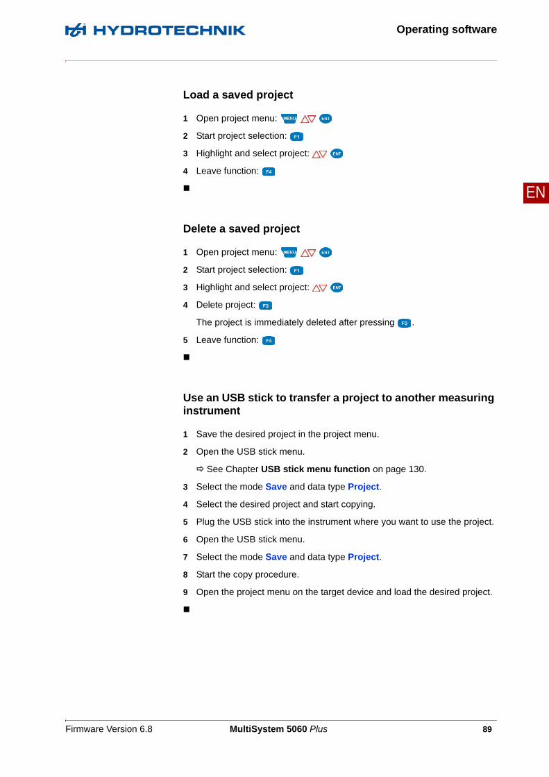
Load a saved project
1 Open project menu:
2 Start project selection:
3 Highlight and select project:
4 Leave function:
Delete a saved project
1 Open project menu:
2 Start project selection:
3 Highlight and select project:
4 Delete project:
The project is immediately deleted after pressing .
5 Leave function:
Use an USB stick to transfer a project to another measuring instrument
1 Save the desired project in the project menu.
2 Open the USB stick menu.
See Chapter USB stick menu function on page 130.
3 Select the mode Save and data type Project.
4 Select the desired project and start copying.
5 Plug the USB stick into the instrument where you want to use the project.
6 Open the USB stick menu.
7 Select the mode Save and data type Project.
8 Start the copy procedure.
9 Open the project menu on the target device and load the desired project.

Firmware Version 6.8 MultiSystem 5060 Plus 90
Operating software
EN
Special applications submenu
This submenu contains several functions which enhances the functionality of the MS 5060 Plus or which are required for the operation of external devices:
Use to highlight the desired submenu and then press .
HYDROrun Execution of pre-defined test sequences
CANopen device You may start and stop a connected CANopen device here
Particle counterPATRICK
Display and save the data of the particle counter
Load valve Readout of the data and activation of the HYDROTECHNIK load valve HyS-ense QL 326

Firmware Version 6.8 MultiSystem 5060 Plus 91
Operating software
EN
HYDROrun
Use the HYDROrun menu to select, setup, start and evaluate predefined test procedures. The measuring system is delivered with some example test pro-cedures that provide insight into the virtually unlimited possibilities of the software package HYDROgen/HYDROrun.
Open the menu
Open the menu ( ) and a screen with two menu entries and two (four if a test procedure is already loaded) functions will be displayed:
License requiredYou need a valid license for your measuring system to use the HYDROrun func-tionality. The license includes a release code which you can enter in the HYDRO-run menu (see HYDROrun settings on page 93). Please contact your HYDROTECHNIK partner for more information.

Firmware Version 6.8 MultiSystem 5060 Plus 92
Operating software
EN
Procedure Opens and loads a test procedure
Description Shows the description of the loaded test procedure
The functions and are only shown, if a test procedure is loaded:
Select test procedure
1 Open HYDROrun menu:
2 Start the selection of a test procedure:
3 Highlight and select a test procedure:
START Starts the loaded test procedure
SETUP Opens a submenu with important HYDROrun settings
DELETE Deletes the loaded test procedure
D-BASE Results of test procedures can be saved in databases; with this function you can select and display these databases

Firmware Version 6.8 MultiSystem 5060 Plus 93
Operating software
EN
HYDROrun settings
After pressing in the HYDROrun Menu, a screen will be displayed where you can enter the HYDROrun release code and configure the memory re-served for the HYDROrun .
If no release code has been entered yet, the memory configuration can not be modified. If a release code has been entered, this cannot be selected and modified.
You can decide, how much space can be reserved for HYDROrun on the SD card:
Test procedures Memory that is to be reserved for test procedure files
Measurements Memory that is to be reserved for temporary measurement files that may be created during the execution of test procedures
Databases Memory that is to be reserved for databases that might be created for interme-diate or end results of test procedures

Firmware Version 6.8 MultiSystem 5060 Plus 94
Operating software
EN
This is how to configure the HYDROrun memory
1 Highlight the desired memory:
2 Select the desired memory size:
3 Repeat steps 1 and 2 for the other memory types.
4 Confirm the setting with .
5 Confirm the query about whether the SD card is to be formatted, to apply the changed memory settings.
Supplied test procedures
These demonstrate the possibilities of the HYDROgen/HYDROrun software package from HYDROTECHNIK and how measurement values can be indi-vidually displayed.
The following test procedures are available for new deliveries of the measuring instrument and after each time the SD card has been formatted.
Four Displays (English) Presentation of the measurands p1, p2, T1 and Q1 on four large-scaled dis-play sections.
Values as bargraph(English)
Presentation of the measurands p1, p2, p3 and Q1 as bar diagrams.
Note
Loss of data possibleThe SD card will be formatted after modifying the memory settings. All contained data (e.g. measuring series) will be lost.• Save this data to a USB stick before you modify the memory settings.

Firmware Version 6.8 MultiSystem 5060 Plus 95
Operating software
EN
Cylinder alignment(English)
Synchronity test of two lifting cylinders of a bulldozer.
This test procedure also tests whether the correct sensors are connected to the instrument. This avoids faulty measurements due to incorrect sensors. A bar diagram shows the cylinder pressures p1 and p2, and the pressure difference.
The test is OK, if both pressure values are 145 bar (± 5 bar) at the final stop and the pressure difference is smaller than 5 bar.
Nine Displays (English) Presentation of the measurands p1, p2, p3, p4, T1, T2, Q1 and Q2 on nine large-scaled display sections.
Displays + Bargraph(English)
Presentation of the measurands p1 and p2 on two large-scaled display sec-tions and of Q1 as a bargraph.
Valve Test (English) Serial testing of valves This test checks whether the valves open at a defined pressure.
Pressure is also measured when a flow rate (> 0.2 l/min) is detected. The valve must open at a pressure of 1.5 bar (± 0.2 bar). The test result is stored in a database that can be evaluated in the instrument and transferred to a PC (transfer with HYDROrun).
Arithmetic Test(English)
Graphical presentation of measured and calculated variables with HYDRO-gen/HYDROrun.
Single Value Storing(English)
Single value storing (English) – Storing the measured values p1 and Q1 with key press (storage of individual value). If pressure value exceeds 200 bar, an alarm will be displayed. If pressure falls below 1 bar, the single value storing will be ended with a key press. At the end, a statistic will be shown and then a graphical presentation of the measured values.

Firmware Version 6.8 MultiSystem 5060 Plus 96
Operating software
EN
Inspect. servo valves(English)
Inspection of servo parts.
The control voltage of the valve, pressure p1 and flow rate are measured. The connected sensors are checked prior to the test run. The user will be informed about errors. The control voltage must be set to 0 V for the test. The control voltage must be increased to 10 V within five seconds. After completing the test, the user can select from several display options of the test results.
CANopen device
If one or multiple CANopen devices are connected to the MS 5060 Plus, you can use to give the command to start (ID = 0, DLC = 2, data: 0x01 - 0x00), or with the command to stop (ID = 0, DLC = 2, data: 0x80 - 0x00; pre-op-erational mode).
Information on how to configure the MS 5060 Plus for a CANopen device, see chapter Chapter CAN configuration on page 74 and Chapter Define CAN channel on page 138.

Firmware Version 6.8 MultiSystem 5060 Plus 97
Operating software
EN
Patrick the Particle Counter
Use the MultiSystem 5060 Plus to configure Patrick the optical particle mon-itor and read-out its measured values. This is done with two functions and a submenu.
Highlight the Particle counter PATRICK entry. Two functions are displayed in the status bar:
Before starting to operate Patrick you should check in the Device submenu (see Chapter CAN configuration on page 74) whether the CAN bus baud rate is set to the same value like at the particle counter (see type plate). Additionally, the func-tion PowerCAN must be set to ON in the Setup menu (see Chapter Dialogue Setup (1/2) on page 82).
CONFIG reprograms channels of the MultiSystem 5060 Plus required to permanently display the measured value of the particle counter;
an existing configuration of these channels will be overwritten
SHOW opens a dialogue where the measured values and some sta-tus information of the particle counter are displayed; the required channels of the MultiSystem 5060 Plus are repro-grammed temporarily, the prior configuration will be restored after leaving the function

Firmware Version 6.8 MultiSystem 5060 Plus 98
Operating software
EN
Configure the Particle Counter
In the Special applications menu, highlight the Particle counter PATRICK entry and press . The first of two configurations is displayed.
Node ID Enter the ID of the particle counter you want to configure; the ID can bee found on the type plate
Readout Select whether you would like the purity classes to be displayed according to ISO or SAE
Particle x μm Activate the size classes that you would like to display
Channel Assign a channel of the MultiSystem 5060 Plus to each activated size class

Firmware Version 6.8 MultiSystem 5060 Plus 99
Operating software
EN
Press to display the 2nd configuration page.
First press to read the current measuring and interval time from the parti-cle counter:
Meas. period Duration of a particle counting
Interval time Time interval between two measurements
You can modify the values, then press to transmit the parameters to the particle counter.
Press to complete the programming.

Firmware Version 6.8 MultiSystem 5060 Plus 100
Operating software
EN
Measured value window with display of the particle classes
Press while Particle counter PATRICK is highlighted in the Special ap-plications menu. This configures the required channels automatically.
Then return to the measured values display:
The current measured values for the four classes are displayed. You can se-lect additional channels to be displayed.

Firmware Version 6.8 MultiSystem 5060 Plus 101
Operating software
EN
Measured value display with the Presentation function
Press while Particle counter PATRICK is highlighted in the Special ap-plications menu. A warning hint is displayed first:
Patrick is switched into Device mode for the Presentation function. Patrick au-tomatically switches to standard mode after this function is completed. If the function is not completed properly, Patrick remains in Device mode and adds a value to the history memory every four seconds. This quickly overwrites the existing history data and a long-term documentation can no longer take place.

Firmware Version 6.8 MultiSystem 5060 Plus 102
Operating software
EN
Press to open the SHOW function:
The current measured values of the particle classes are displayed together with several status values of the particle counter. The flow control bargraph turns red when the volume flow rate is outside the allowed limits.
SAE displays the SAE particle classes
HISTOR shows the content of the history memory of the particle coun-ter
Q-CTRL Use this function to request measuring data faster from Pat-rick to be able to see flow changes earlier in the bargraph

Firmware Version 6.8 MultiSystem 5060 Plus 103
Operating software
EN
History memory of the particle counter
You can read out and display the data from the history memory of the particle counter:
Meas. series xx Proposed name for the measured value file created with the history data; this can be overwritten
Serialnumber Display of the serial number of the particle counter
Number of records Number of data sets in the history memory
Status Number of transmitted data sets; if > 0 the SHOW function is displayed
There are three functions available:
READ reads the data from the history memory
DELETE clears the history memory of the particle counter
SHOW displays the read history data as a table

Firmware Version 6.8 MultiSystem 5060 Plus 104
Operating software
EN
Display history data
The history data is displayed as a table with five columns. A maximum of elev-en data sets are displayed at a time.
The columns show (from left to right):
• Date, time of day
• ISO class 4 μm
• ISO class 6 μm
• ISO class 14 μm
• ISO class 21 μm
Press to close the data table view.
SAE shows the particle classes according to SAE
DETAIL shows the data sets between the highlighted ones and the ones in the next line (only available if more data sets than lines)
RESET returns from the detail view

Firmware Version 6.8 MultiSystem 5060 Plus 105
Operating software
EN
Load valve
Use the MultiSystem 5060 Plus to program and operate the electronically-controlled load valve HySense QL 326 :
Program the load valve on page 107
Operate the load valve on page 114
Parameter shows the current configuration of the load valve.
Press to program the load valve.
See Program the load valve on page 107.
You can only program the load valve if is INACTIVE.

Firmware Version 6.8 MultiSystem 5060 Plus 106
Operating software
EN
Device / QL-326 Device is displayed if no load valve is connected with the measuring instrument.
If a load valve is connected with the measuring instrument, the short name of the load valve will be displayed (example: QL-326).
• INACTIVE
The load valve is not active.
– You can configure the parameters of the load valve
– You can not operate the load valve.
• Connected
The connection to the load valve is active.
– You can operate the load valve.
Heartbeat Indicates whether the measuring instrument is able to communicate with the load valve.
• ???
The measuring instrument has not found any load valve to communicate with.
• ACTIVE
The measuring instrument can communicate with the load valve.
The code in front of ACTIVE indicates the state of the communication. Please contact customer service for the code, if necessary.
Software shows the software version of the load valve.

Firmware Version 6.8 MultiSystem 5060 Plus 107
Operating software
EN
Program the load valve
Here is how to open the load valve dialogue (1/2)
1 Press to open the menu.
2 Use to highlight the Special applications entry and press .
3 Use to highlight the Load valve entry and press .
4 Use to highlight the Parameter entry and press .
You can define the load valve behaviour in the Load valve (1/2) dialogue:
Operation mode Use to select your desired operating mode:
• ramp
The valve follows the curve of a defined ramp.
See Program Ramp mode on page 108.
• sine
The valve follows a sine curve.
See Program Sine mode on page 110.
• Inactive
The load valve is switched off.
• Manual
The valve of the load valve is controlled with and .
You can only program the load valve if is INACTIVE.

Firmware Version 6.8 MultiSystem 5060 Plus 108
Operating software
EN
Mode Use to select from the following options:
• CYCLIC
Ramp/Sine is followed repeatedly. The number of repetitions is defined under Nbr. of cycles.
• SINGLE VAL
Ramp/Sine is followed exactly one time.
Nbr. of cycles Enter the number of repetitions for the load (ramp/sine).
For Mode, CYCLIC must be selected.
Program Ramp mode

Firmware Version 6.8 MultiSystem 5060 Plus 109
Operating software
EN
The load valve follows the curve of a ramp that can be defined with four sec-tions. The values shown in the dialogue result in this ramp:
Highlight the setpoints of the ramp, press and enter the desired value.
Then press .
Start / End This input corresponds t the Volt value as percentage of the maximum output voltage.
Duration Time values as a multiple of 10 ms.
Picture: Values for ramp operation mode

Firmware Version 6.8 MultiSystem 5060 Plus 110
Operating software
EN
Program Sine mode
The load valve follows a sine curve that can be defined with three parameters. The values entered in the dialogue result in the shown curve:
Picture: Values for sine operation mode
A Amplitude of the curve
O Offset between zero and the base line of the curve
F Frequency

Firmware Version 6.8 MultiSystem 5060 Plus 111
Operating software
EN
Highlight the setpoints of the curve, press and enter the desired value.
Then press .
Amplitude This input corresponds t the Volt value as percentage of the maximum output voltage.
Offset This input corresponds t the Volt value as percentage of the maximum output voltage.
Frequency Enter frequency as a multiple of 10 mHz.
Make sure that the sum of Amplitude and Offset is less than 100 %.

Firmware Version 6.8 MultiSystem 5060 Plus 112
Operating software
EN
Program channels
Press to display the Load valve (2/2) dialogue.
Seven channels are required for the operation of the load valve.
• Three channels for the display of the measured values:
– Pressure
– Temperature
– Flow
• One channel for the display of the valve voltage of the load valve.
– Ctrl voltage
• Two channels for the communication between measuring instrument and load valve:
– Status
• One channel for the status query:
– Heartbeat
Highlight the desired channel, press and modify the channel assignment.
Then press .

Firmware Version 6.8 MultiSystem 5060 Plus 113
Operating software
EN
End program
Press to end the load valve programming and save your input.
If the channels of the load valve are not displayed in the measured values dis-play, the measuring instrument will offer to insert the channels in the measured value display.
If necessary, modify the settings of the measured values display in the Display submenu.
See Display submenu on page 58.
YES The measured values of the load valve are inserted in the measured values display.
NO No adaptation of the measured values display is carried out.

Firmware Version 6.8 MultiSystem 5060 Plus 114
Operating software
EN
Operate the load valve
The following prerequisites must be given to be able to operate the load valve with the measuring instrument:
• The load valve is connected with the measuring instrument and ready for operation.
• The communication between measuring instrument and load valve is functioning. A Heartbeat is displayed.
See Load valve on page 105.
• The load valve is programmed.
See Program the load valve on page 107.
Activate the load valve
1 Press to open the menu.
2 Use to highlight the Special applications entry and press .
3 Use to highlight the entry QL-326 (device) and press .
Next to the entry QL-326, connected will be displayed.
4 Press until the measured values display is shown.

Firmware Version 6.8 MultiSystem 5060 Plus 115
Operating software
EN
Now the function bar at the lower screen edge has two functions. Press to toggle between the functions:
The special function bars have these functions:
When you have ended the measurement, you can deactivate the load valve again.
Picture: Standard function bar
Picture: Function bar during operation mode Ramp or Sine
Picture: Function bar during operation mode Manual
START starts the load valve.
Yellow: The load valve can be started.
Green: The load valve is started and is taking place. The but-ton has no function:
STOP stops the load valve. Stops the load valve, valve will be opened and the full volume flows through the load valve.
Yellow: The load valve is started and can be stopped.
Red: The load valve is not started. The button has no func-tion:
Opens the valve of the load valve.
(operation mode Manual only)
Closes the valve of the load valve.
(operation mode Manual only)
HOLD “freezes” the measured values display.
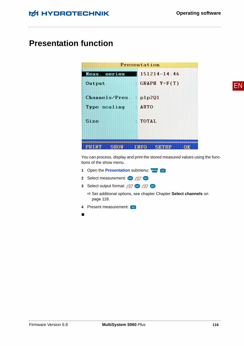
Firmware Version 6.8 MultiSystem 5060 Plus 116
Operating software
EN
Presentation function
You can process, display and print the stored measured values using the func-tions of the show menu.
1 Open the Presentation submenu:
2 Select measurement:
3 Select output format:
Set additional options, see chapter Chapter Select channels on page 118.
4 Present measurement:

Firmware Version 6.8 MultiSystem 5060 Plus 117
Operating software
EN
Select measurement:
1 Open Presentation menu:
2 Select measurement:
• You can press to display the name of the measurement file instead of the recording time.
• Press while a measurement is highlighted to display information about the measurement.Date and time of the measurement, storing time and scanning rate, and possible trigger settings will be displayed.
• Notes, which were entered at the start of the storing, are shown on the second information page. You can edit the notes.
Select output format
The data of the selected measurement can be presented in four different ways:
• Table: Presentation of all measured values of each channel in a table
• Statistics: Presentation of the minimum, maximum and average values of each channel
• Graph: Two different graphical presentations; one depending on time, the other depending on a selected variable
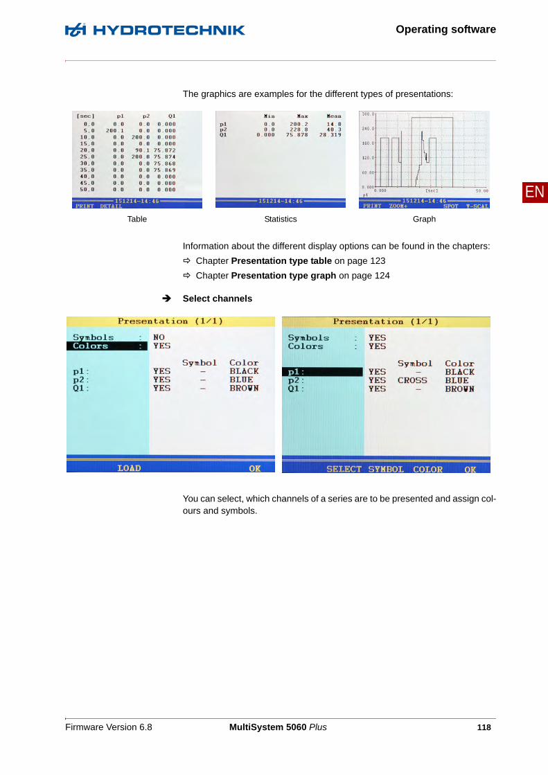
Firmware Version 6.8 MultiSystem 5060 Plus 118
Operating software
EN
The graphics are examples for the different types of presentations:
Information about the different display options can be found in the chapters:
Chapter Presentation type table on page 123
Chapter Presentation type graph on page 124
Select channels
You can select, which channels of a series are to be presented and assign col-ours and symbols.
Table Statistics Graph

Firmware Version 6.8 MultiSystem 5060 Plus 119
Operating software
EN
Symbols Select whether symbols are to be used for the presentation of the channels
Colors Select whether colours are to be used for the presentation of the channels
Channels These functions are available when one of these two lines is highlighted (only when the option is set to YES):
Highlight one of the displayed channels to modify symbols and colours for it.
You can use one of two methods:
• Press one of the F-keys, select a setting and press
• Press repeatedly to step through the options, select the settings and the press
These functions are available when one of the channels is highlighted:
HELP shows helpful information about this dialogue
LOAD loads the settings for symbols and colours from the display menu
OK saves the settings and closes the dialogue
SELECT allows you to select/deselect the channel
SYMBOL opens the list for selecting a symbol
COLOR opens the list for selecting a colour
OK saves the settings and closes the dialogue

Firmware Version 6.8 MultiSystem 5060 Plus 120
Operating software
EN
Define scaling
By default, the entire measuring range of a variable is used as scaling.
However, if you want to limit the presentation to a certain part of the measuring range, you can enable the manual scaling:
1 Select Type scaling:
2 Select MANUAL:
3 Select Scaling:

Firmware Version 6.8 MultiSystem 5060 Plus 121
Operating software
EN
Enter minimum and maximum values
You can set the minimal and maximal values of the measured values to be pre-sented here.
• For p1 and Q1 the complete measuring range (0 – 200 bar, resp. 0 – 300 l/min) is to be displayed.
• For p2 only the measurement values which lie between 40 and 100 bar are to be displayed.
You may use the function keys to ease the manual scaling:
This is how to change the scaling of a variable:
1 Select variable:
2 Enter minimal value and .
3 Enter maximum value and .
4 Save scaling and close:
LOAD loads the measuring ranges of the channels and shows them as scaling
AUTO checks the measured values of all channels and shows the actual measuring ranges rounded as scaling
AUTO-S checks the measured values of the highlighted variable and shows the actual measuring range as scaling
OK saves the settings and closes the dialogue

Firmware Version 6.8 MultiSystem 5060 Plus 122
Operating software
EN
Define size
By default, measurements are presented completely. But you may limit the range of presented values by entering a start and end time. In the example shown, only the range between 2.5 and 5.0 seconds is be shown.
This is how to adapt the range of presentation:
1 Select Size:
2 Select CLIPPING:
3 Enter the From time: Value
4 Enter the To time: Value

Firmware Version 6.8 MultiSystem 5060 Plus 123
Operating software
EN
Presentation type table
Independently of the recording time, a table will always contain eleven lines:
• Start and end value
• Nine intermediate values
You can zoom into the table to display intermediate values between two dis-played values:
1 Press .
2 Use to highlight the lines below which you would like to display the intermediate values.
3 Press .
The highlighted value becomes the start and the next the end value, between that nine intermediate values are displayed; if not enough values are contained in the measuring series to display nine values between the start and end value, the next ten measuring values will be displayed after the start value.
4 You can now repeat these steps to show more detailed values, or press to undo the zooming step-by-step.

Firmware Version 6.8 MultiSystem 5060 Plus 124
Operating software
EN
Presentation type graph
The selected channels are displayed with the assigned symbols and colours.
You can use the zoom function to enlarge certain areas of the graph. You have the following options:
PRINT Print graph
ZOOM+ Zoom into the graph
Zoom out in steps
SPOT Use spot function (see Spot function on page 126)
Y-SCAL Toggle the channel for which the scaling is displayed at the y-axis (see Meaning of the scaling locations on page 125)

Firmware Version 6.8 MultiSystem 5060 Plus 125
Operating software
EN
1 Enable zoom function:
A yellow rectangle indicates the area that will be enlarged.
You can move and scale the rectangle:
2 Move rectangle:
3 Scale rectangle:
4 Display yellow area (apply zooming):
You can use the zoom function repeatedly to show the desired area of the graph in an optimised way.
5 End graph presentation:
Meaning of the scaling locations
The upper right graphic shows the presentation with GLOSS scaling location, that means the scaling of the displayed channels is shown beneath the graph beside the channels. This gives more room for the graph.
The Y-AXIS scaling location (see upper left graphic) shows the scaling of one channel on the y axis.
Press to toggle between the scaling of all displayed channels. The chan-nel whose scaling is currently displayed is shown beneath the y axis.
The scaling location can be changed in the setup of the presentation menu (see Chapter Dialogue Setup for Presentation on page 127).

Firmware Version 6.8 MultiSystem 5060 Plus 126
Operating software
EN
Spot function
You can use the spot function to display measured values of a certain time po-sition within the graph:
1 Activate spot function:
2 Choose move factor:
3 Move spot line:
Press the key during the spot function to select different move factors.
4 Read measured values.
5 End spot function:

Firmware Version 6.8 MultiSystem 5060 Plus 127
Operating software
EN
Delta spot function
If you press the key while the graphic is displayed, two new function key assignments will be displayed:
For the delta-spot function, two spot lines are displayed.
For scaling location Y-AXIS, the differences between the measured values marked by the spot lines are displayed in a rectangle in the upper right corner.
For scaling location GLOSS, the distance between the spot lines is displayed as a bold number between the spot lines at the x-axis.
Like in the spot function, you can now choose move factors with the keys and select with whether the left (x1), right (x2) or both spot
lines are to be moved.
Dialogue Setup for Presentation
Use delta-spot function
Print screen

Firmware Version 6.8 MultiSystem 5060 Plus 128
Operating software
EN
You can modify the basic structure of the graphic presentation in the Setup submenu.
1 Open the Setup submenu:
2 Highlight function:
3 Select setting:
4 Exit the Setup submenu:
Grid Number of the displayed lines in the grid of the diagram (no Grid, 5 Lines, 10 Lines, Zero Lines).
Channel selection Choose from the following options:
• AUTO: For presentation of a different measurement, all channels of this measurement will be selected automatically for the presentation
• MANUAL: When presenting other measurements, the last channel selected remains, if possible
Position scaling defines how the scaling of the channels is displayed.
• For GLOSS, the scaling is displayed beneath the graph.
• For Y-AXIS, only the scaling one channel is shown on the y axis. There is remaining space for the graphic.
Press to browse the scaling of the channels shown.

Firmware Version 6.8 MultiSystem 5060 Plus 129
Operating software
EN
Delete series function
Use the functions of this menu to delete stored measurements.
In the graphic, the measurement series 002 and 003 are selected for deletion. The measurement series 001 is highlighted. Press to display information on it.
1 Open delete menu:
2 Select Delete Single or Delete All:
For Delete All, continue with step 6.
3 For Delete Single, select desired measurement:
A * will be displayed next to the measurement.
Press to display information on the currently highlighted measurement.
4 Repeat step 3 until all desired series of measurements are selected.
5 Start deletion:
6 Confirm deletion with or cancel with .
The deletion cannot be undone.

Firmware Version 6.8 MultiSystem 5060 Plus 130
Operating software
EN
USB stick menu function
With the functions of the USB stick menu you can move files between the stick and the measurement system, and display information on the USB stick.
Saving to the USB stick
To transfer files from the SD card of the measuring instrument onto a USB stick, proceed as follows:
1 Open the USB stick menu:
2 Select Save mode:
3 Select Data type:
• Measurements (mwf files)
• Project data (prj files)
• Sensor databases (sdb files)
• CAN parameter databases (cdb files)
4 Select files.
See Select files on page 131.
5 Define default name.
See Define default name on page 132.
6 Start copying:
Menu is not displayed all the timeThe USB stick menu will only be displayed if a USB stick is plugged and detected. Please observe the requirements for the USB stick as described in chapter Chap-ter How to use the USB stick on page 149.

Firmware Version 6.8 MultiSystem 5060 Plus 131
Operating software
EN
Select files
There are three functions available making file selection easier:
1 Highlight Select in the USB stick menu:
2 Open the Select submenu:
3 Select desired file(s):
Selected files are marked with a * to the left next to the line (here the files 001 and 006).
4 End selection:
FILE Shows the names of the files
ALL Selects all files
INFO Displays additional information on the selected file

Firmware Version 6.8 MultiSystem 5060 Plus 132
Operating software
EN
Define default name
When copying files to the USB stick, only the 8.3 name convention is support-ed. All files will therefore be renamed. Here you may define a prefix for the new file names. Since the name may only have eight characters, you should leave enough space for a consecutive numbering of the files.
1 Highlight Default name in the USB stick menu:
2 Start definition:
3 Enter desired prefix; you may use all alphanumeric characters.
4 Confirm prefix:

Firmware Version 6.8 MultiSystem 5060 Plus 133
Operating software
EN
Load files from the USB stick
To transfer files from the USB stick to the measuring instrument, proceed as follows:
1 Open the USB stick menu:
2 Select mode Load:
3 Select Data type:
• Measurements (mwf files)
• Project data (prj files)
• Sensor databases (sdb files)
• CAN parameter databases (cdb files)
4 Select files.
See Select files on page 134.
5 Start copying:

Firmware Version 6.8 MultiSystem 5060 Plus 134
Operating software
EN
Select files
There are two functions available during the file selection:
1 Highlight Select in the USB stick menu:
2 Open the Select submenu:
3 Select desired file(s):
Selected files are marked with a * left next to the line.
4 End selection:
DELETE Deletes the marked file(s) from the USB stick
COPY Copies the marked file(s) from the USB stick to the SC card of the instrument

Firmware Version 6.8 MultiSystem 5060 Plus 135
Operating software
EN
Display information about the USB stick
You can display information on the detected USB stick by pressing while the USB stick menu is displayed. Then the memory capacity of the stick is test-ed, which may take up to four minutes. A screen will subsequently appear, as can be seen in the example graphic.
Here you can see the size of the total and available memory as well as a list of files contained on the stick that are interesting for the MultiSystem 5060 Plus. Press to leave the submenu.
Waiting time up to four minutesIf information is to be displayed on the USB stick, the memory capacity of the stick is tested. This can take up to four minutes depending on the capacity of the USB stick.

Firmware Version 6.8 MultiSystem 5060 Plus 136
Special functions
EN
Special functions
Special functions of the instrument, which have been referred to in the previ-ous sections, are explained here.
Linearisation table
The linearisation table can be utilized to compensate for sensor inaccuracies. By calibrating a sensor, you will obtain this table, which can be entered into the measuring instrument. Five different linearisation tables, each with ten values are available for each measuring channel.

Firmware Version 6.8 MultiSystem 5060 Plus 137
Special functions
EN
1 Select the option YES at the Linearisation menu option. .
2 Highlight Table: .
3 Either highlight a stored table, or an empty line if you want to enter a new table: .
4 Highlight the entry ID.- Number: .
5 Enter a name for the new table: .
6 Highlight Ref.-Point 1: .
7 Enter the first set value: .
8 Enter the first actual value: .
9 Repeat steps 7 and 8 for all required lines of the table.
10 Complete the entry of set and actual values: .
11 Confirm the table: .
The new table is selected as active.

Firmware Version 6.8 MultiSystem 5060 Plus 138
Special functions
EN
Define CAN channel
After you have set a calculation channel to CAN, you can enter variable and unit freely. Then you have to define the CAN parameters. Please have the doc-umentation of the CAN sensor or the MultiXtendavailable; all required information can be found here.
1 Highlight CAN- parameters: .
2 Select the CAN specification: .
3 Enter the timeout: .
4 Enter the identifier as a decimal number.
The corresponding value is displayed in hexadecimal numbers and the corresponding decimal value stands in brackets – .
5 Select the data format: .Further input options are displayed depending on the selected format.
After entering all CAN parameters you can assign a name and store them:
1 .
2 – enter a name, use to toggle between the entry of capital and small letters – .
3 – store entered name.
Note
The CAN bus must be activated in the device menu to enable the use of a CAN channel. See chapter Chapter CAN configuration on page 74

Firmware Version 6.8 MultiSystem 5060 Plus 139
Special functions
EN
CAN original format When entering the CAN specifications you may select the ORIGINAL format. Then, the CAN data will not be interpreted by the measuring instrument, but saved digitally in the measurement file. During the subsequent data evaluation with HYDROcom 6, these data can be interpreted.
This allows the recording of so called “Multichannels”. These are channels containing data from several sources, e.g. switch positions (max. 64 switches in one channel) or different sensor signals.
If you want to record CAN original data, you will only have to define the number of Offset-Bits (bits at the beginning of a CAN message that shall be left out) and Data-Bits (bits after the offset that shall be recorded).
Display of Multichanneldata
If you include a Multichannel into the measuring display, no measured values but a hexadecimal number in blue digits will be shown. In a max. 5-digit hex number, up to 20 sub-channels can be displayed. If the channel contains more sub-channels, the last four hex digits will be displayed together with a ~ in front of them.
Use of Multichannels Many machine states (pump on, blinker off, rear light on, motor on, …) are en-coded in a CAN message with a single bit. By default, a separate measuring channel of the instrument must be used for each status / status bit. With the Multichannel function, all status bits can be collected with one single channel, you may later use HYDROcom 6 to separate this into the single status infor-mation. You may also use HYDROcom 6 to combine single bits of a Multichannel to one measured value. This allows to collect several measured values using one channel of the MS 5060 Plus. Due to the HEX format, a read-able display of these measured values in the instrument is not possible.

Firmware Version 6.8 MultiSystem 5060 Plus 140
Special functions
EN
Examples
Here you save all 32 bits of a Multichannel.
Here, you save data bits 8 to 15.
Here you save the data bits 6 to 31. If you do not want to save the “uninterest-ing” bits 8 to 13 and 16 to 23, you will have to assign the Multichannel to three special channels and define different settings:
• 1. Channel: Bit offset 6, data bits 2;
• 2. Channel: Bit offset 14, data bits 2;
• 3. Channel: Bit offset 24, data bits 8
.
Format: ORIGINAL
Bit offset: 0
Data bits: 32
Format: ORIGINAL
Bit offset: 8
Data bits: 8
Format: ORIGINAL
Bit offset: 6
Data bits: 26

Firmware Version 6.8 MultiSystem 5060 Plus 141
Special functions
EN
Here the measured values of a temperature (bits 0 to 7) and a pressure sensor (bits 8 to 15) are coming on one Multichannel. With the shown specifications, you record the measured values of both channels, but they cannot be dis-played at the measuring instrument. The decoding will be done later using HYDROcom 6.
You need two special channels to display the measured values with the MultiSystem 5060 Plus.
• On the first one, you define for the temperature sensor: Format = BINARY, bit offset = 0, data bits = 8.
• For the pressure sensor, you require a different special channel and define here: Format = BINARY, bit offset = 8, data bits = 8
Format: ORIGINAL
Bit offset: 0
Data bits: 16

Firmware Version 6.8 MultiSystem 5060 Plus 142
Special functions
EN
Graphic presentation in display menu
After configuring the graphic presentation in the display menu (see Chapter Display submenu on page 58) in the measured values display, the measured values will then look like this, for example:
• Channel p1 is displayed as blue line with circles
• Channel T1 is displayed as red line with squares
• The current measured values are displayed beneath the graph
• The vertical black line in the centre of the graph indicates the current measuring position
You can use the following functions:
MINMAX switches to the graphical presentation of MinMax values
<VAL.> displays scaling information instead of measured values
HOLD stops the actualisation of the measured values ("freezes" the display)

Firmware Version 6.8 MultiSystem 5060 Plus 143
Special functions
EN
Couple several instruments
You can couple several MultiSystem 5060 Plus measuring instruments and increase the number of available input channels with nearly no limitations. But please be aware that the parameters scanning rate, storage time and pretrig-ger must be programmed identically at all coupled measuring instruments.
Connecting a measuring instrument electrically
Couple two instruments Use the connection cable TKZ 8824-F2-00.50 and connect the digital input/output jacks.
Couple severalinstruments
Use the connection cable for external trigger TKZ 8824-D8-04.00 and couple the instruments serial or parallel:
Note
Malfunctions possible!Only use the connection cables available from HYDROTECHNIK to connect the instruments.Otherwise there is the risk of malfunctions.
A Digital input/output
A
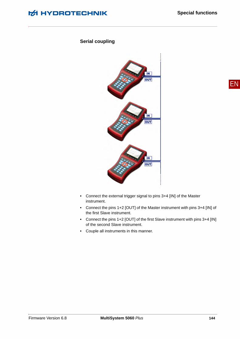
Firmware Version 6.8 MultiSystem 5060 Plus 144
Special functions
EN
Serial coupling
• Connect the external trigger signal to pins 3+4 [IN] of the Master instrument.
• Connect the pins 1+2 [OUT] of the Master instrument with pins 3+4 [IN] of the first Slave instrument.
• Connect the pins 1+2 [OUT] of the first Slave instrument with pins 3+4 [IN] of the second Slave instrument.
• Couple all instruments in this manner.
Firmware Version 6.8 MultiSystem 5060 Plus 145
Special functions
EN
Restrictions of theserial coupling
You will see synchronisation delays with the serial coupling:
• max. 1 ms between Master and Slave 1
• max. 1 ms between Slave 1 and Slave 2
• max. 2 ms between Master and Slave 2
• max. 4 ms between Master and Slave 4
If you operate the coupled instruments in the “dynamic mode” (see section on page Chapter Set hardware filter on page 75) (hardware filter switched off), all channels can be scanned with up to 10 kHz. Then the synchronisation de-lay between two devices is reduced to 0.1 ms.

Firmware Version 6.8 MultiSystem 5060 Plus 146
Special functions
EN
Parallel coupling
• Connect the external trigger signal to pins 3+4 [IN] of the Master instrument.
• Connect the pins 1+2 [OUT] of the Master instrument with pins 3+4 [IN] of all Slave instruments
• Connect pin 2 of the Master instrument via a 2.2 kOhm resistor with pin 3 of a free measuring channel [X]
Firmware Version 6.8 MultiSystem 5060 Plus 147
Special functions
EN
Restrictions of theparallel coupling
The parallel coupling may only be used for the maximum of 10 instruments (1 Master + 9 Slaves). You will see small synchronisation delays of max. 1 ms be-tween all instruments.
Use of the MultiXtend Trigger
For the coupling of more than two instruments we recommend the use of the MultiXtend Trigger (TKZ 316A-00-00.50). This simplifies the coupling and al-lows the use of the standard connection cables (TKZ 8824-F2-00.50).
Programming instruments
Programming Master instrument
1 Program the memory channels as desired.
2 Program scanning rate, storage time and pretrigger as desired.
3 Program the storage start by a trigger (absolutely required, trigger type can be chosen freely).
4 Program the trigger output ACTIVE and set it to SP_TRIG (forwarding of the trigger signal to the Slaves).

Firmware Version 6.8 MultiSystem 5060 Plus 148
Special functions
EN
Programming Slave instruments
1 Program the memory channels as desired.
2 Program scanning rate, storage time and pretrigger in the same way as the Master instrument.
3 Program the storage start by a trigger. For Trigger 1, program the trigger input E1 to ON.
4 Program the trigger output AKTIV and set it to SP_TRIG (forwarding of the trigger signal to the next Slave). This is required for serial coupling, only.
Start recording
Activate the recording at each instrument normally. Please be aware of:
• The trigger incident may not happen at the Master instrument, before all Slave instruments have been activated
• There must be sufficient time between the activation of the storage and the happening of the trigger incident to allow all instruments to store the set pretrigger; otherwise the measuring data cannot be synchronised
Example: the pretrigger is 10 sec (20 % pretrigger at a storage time of 50 sec) and the trigger incident happens 5 sec after the storage activation at the last instrument; this results in a different number of measured values at the coupled instruments
• The storage may not be stopped at any of the coupled instruments, other-wise a synchronisation becomes impossible
• Avoid cyclic storage due to a possible triggering ahead of the desired time
Firmware Version 6.8 MultiSystem 5060 Plus 149
Special functions
EN
Transfer and evaluate measured values
Transfer the measured values from all instruments to a PC. Use the Combine function of the HYDROcom software to combine the measurements.
How to use the USB stick
The USB stick can be used to exchange data and to do a firmware update without using a PC and the software HYDROboot. There are some restrictions for the use of the USB stick:
• USB sticks may only have one partition
• USB sticks must be formatted in the FAT file format
• Bootable USB sticks are not supported (no indication "U3smart" on the stick)
• Only the root directory is supported on the USB stick; subdirectories are not recognized, data cannot be read or written there
• The file names must comply with the 8.3 name convention, longer file names will be shortened automatically

Firmware Version 6.8 MultiSystem 5060 Plus 150
Special functions
EN
Firmware update using the USB Stick
You can use the USB stick to perform firmware updates quickly and easily.
1 Copy the new firmware version onto the USB stick. The file must be located on the top file system level, not in a directory.
2 Switch on the MultiSystem 5060 Plus and wait until the measured values display appears.
3 Plug the USB stick into the USB connector.
4 Open the device menu.
5 Open the setup menu with .
6 Highlight the function USB stick and press .
7 The message Read directory will be displayed and after a short time, the data contained on the stick are displayed.
8 Highlight the file 61_00.BIN“ and press .
9 Confirm the update with (OK).
10 The new firmware version will be loaded and takes about 3 minutes.
11 After loading the firmware, the message Update Firmware will be displayed.
12 Confirm the update with (YES).
Note
Loss of data possible!Back up all data from the SD card before starting the update. Do not switch off the instrument and do not unplug the USB stick while the new firmware version is being loaded. Otherwise there could be malfunctions and loss of data.
Firmware Version 6.8 MultiSystem 5060 Plus 151
Special functions
EN
13 The update will be executed, then the instrument will be switched off automatically.
14 Unplug the USB stick.
15 Switch the device on. The current firmware version number and the selec-tion list of the available operation languages are displayed.
16 Confirm the operation language with . Then the message The software has been updated! Execute RESET? will be displayed. Press to per-form the reset.
17 Wait until the initialization has been executed completely.
Now you can use your MultiSystem 5060 Plus with the new firmware version.
Connect MultiXtend A and T
You can use the MultiXtend A and T to connect additional analogue sensors or thermocouples to the MultiSystem 5060 Plus. Their signals are digitalised by the MultiXtend and transmitted to the CAN input of the measuring instru-ment. The presentation, storage and evaluation of the measuring data is then done in the instrument.
The following steps are required to use the MS 5060 Plus:
• Activate CAN bus
• Program CAN channels
• Activate MultiXtend power supply
• Start the MultiXtend

Firmware Version 6.8 MultiSystem 5060 Plus 152
Special functions
EN
Activate CAN bus
At first you will have to activate the CAN bus in the Device submenu:
1 Open Device submenu:
2 Select function:
3 Set function to ACTIVE:
4 Switch to select the Baudrate:
5 Select desired baud rate:
6 Confirm changes and leave function:
Note
Malfunctions possible!Make sure that the MultiXtend is set to the desired baud rate. Observe item 3 of the short operating instructions.
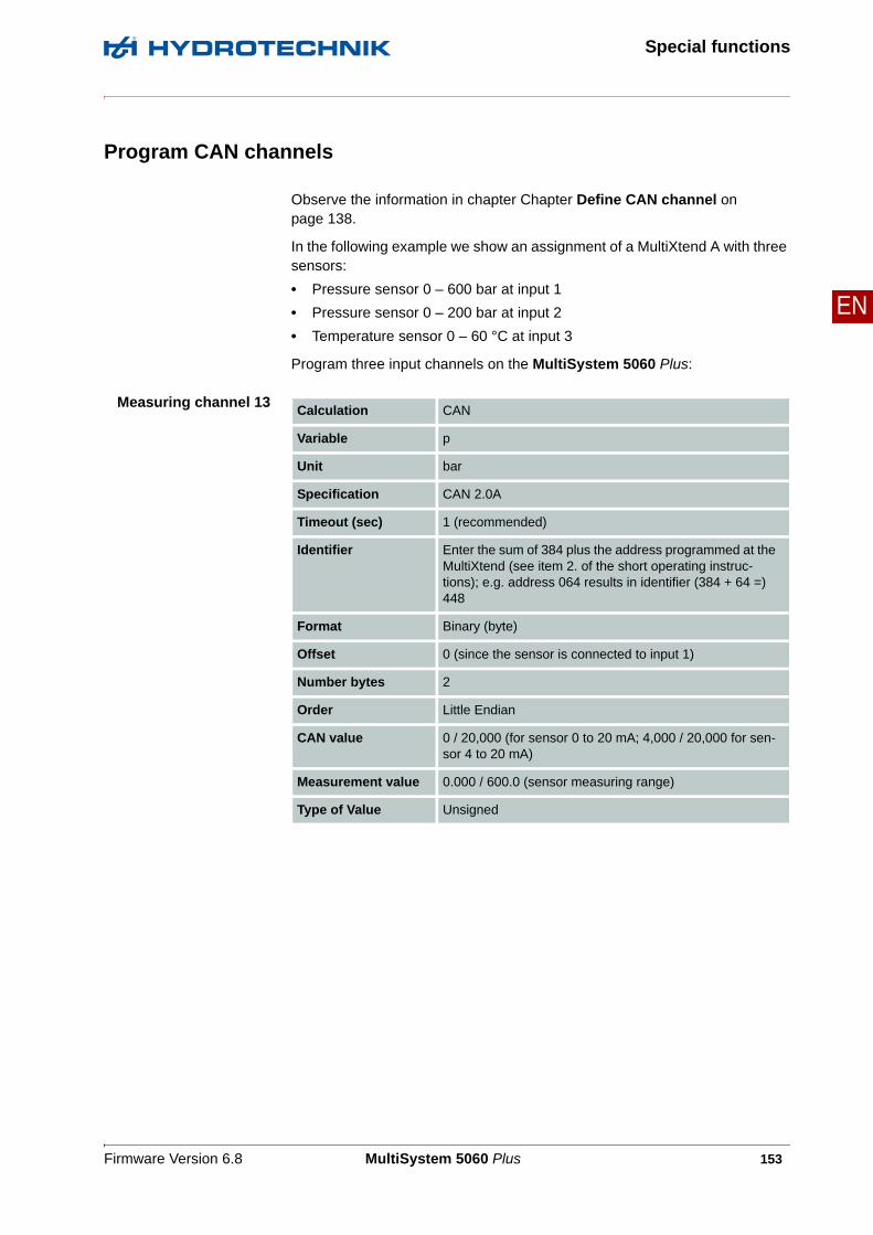
Firmware Version 6.8 MultiSystem 5060 Plus 153
Special functions
EN
Program CAN channels
Observe the information in chapter Chapter Define CAN channel on page 138.
In the following example we show an assignment of a MultiXtend A with three sensors:
• Pressure sensor 0 – 600 bar at input 1
• Pressure sensor 0 – 200 bar at input 2
• Temperature sensor 0 – 60 °C at input 3
Program three input channels on the MultiSystem 5060 Plus:
Measuring channel 13Calculation CAN
Variable p
Unit bar
Specification CAN 2.0A
Timeout (sec) 1 (recommended)
Identifier Enter the sum of 384 plus the address programmed at the MultiXtend (see item 2. of the short operating instruc-tions); e.g. address 064 results in identifier (384 + 64 =) 448
Format Binary (byte)
Offset 0 (since the sensor is connected to input 1)
Number bytes 2
Order Little Endian
CAN value 0 / 20,000 (for sensor 0 to 20 mA; 4,000 / 20,000 for sen-sor 4 to 20 mA)
Measurement value 0.000 / 600.0 (sensor measuring range)
Type of Value Unsigned

Firmware Version 6.8 MultiSystem 5060 Plus 154
Special functions
EN
Meas.Channel 14
Meas.Channel 15
Calculation CAN
Variable p
Unit bar
Specification CAN 2.0A
Timeout (sec) 1 (recommended)
Identifier Enter the sum of 384 plus the address programmed at the MultiXtend (see item 2. of the short operating instruc-tions); e.g. address 064 results in identifier (384 + 64 =) 448
Format Binary (byte)
Offset 2 (since the sensor is connected to input 2)
Number bytes 2
Order Little Endian
CAN value 0 / 20,000 (for sensor 0 to 20 mA; 4,000 / 20,000 for sen-sor 4 to 20 mA)
Measurement value 0.000 / 200.0 (sensor measuring range)
Type of Value Unsigned
Calculation CAN
Variable t
Unit °C
Specification CAN 2.0A
Timeout (sec) 1 (recommended)
Identifier Enter the sum of 384 plus the address programmed at the MultiXtend (see item 2. of the short operating instruc-tions); e.g. address 064 results in identifier (384 + 64 =) 448
Format Binary (byte)
Offset 4 (since the sensor is connected to input 3)
Number bytes 2
Order Little Endian
CAN value 0 / 20,000 (for sensor 0 to 20 mA; 4,000 / 20,000 for sen-sor 4 to 20 mA)
Measurement value 0.000 / 60.00 (sensor measuring range)
Type of Value Unsigned

Firmware Version 6.8 MultiSystem 5060 Plus 155
Special functions
EN
Activate MultiXtend power supply
The MultiXtend can either be supplied by its own power pack, or by the MS 5060 Plus. If the instrument shall supply the required power, this function must be activated:
1 Open the Device menu.
2 Open the submenu Setup:
3 Highlight the function Power CAN.
4 Press to set the function Power CAN to ON.
5 Press to confirm the changes and leave the setup menu.
Start the MultiXtend
After activating the power supply, the MultiXtend must be started. Otherwise it cannot send signals.
1 Open the menu Special applications.
2 Press START.
Note
After a loss of supply power or the measuring instrument has been switched off, the MultiXtend must be started again.

Firmware Version 6.8 MultiSystem 5060 Plus 156
Special functions
EN
Connection of external measuring devices
You can connect external measuring devices (e.g. Multimeters) to the RS232 interface of the MultiSystem 5060 Plus and assign the measuring signals to a special channel. The measuring devices must support the output data format “Voltcraft” or “Metex”.
Configuration in thechannel menu
You can assign the output signal of the external device to any special channel. Open the parameters of the desired channel in the channel menu (see Chap-ter Configure special channels (C11 ... 24) on page 53) and set the parameter Calculation to multimeter.
Then you will have to select the output signal type of the device (Voltcraft VC 820, Metex, or Voltcraft VC 9x0) and assign a name to the channel. Press to save the channel settings. Then you may use this channel for dis-play, recording and calculations as any other channel.
Note
In certain circumstances, a "Send" command must be given to the connected multimeter in order to initiate the communication. Please observe the operating instructions of the multimeter.

Firmware Version 6.8 MultiSystem 5060 Plus 157
Special functions
EN
Viscosity-compensated volume flow rate measuring
The oil viscosity depends on its temperature. To account for these variations during the measurement of the volume flow, three channels must be corre-spondingly programmed:
• One measuring channel for temperature (if the viscosity of the oil is not known)
• One measuring channel for the viscosity-compensated volume flow rate measurement
• One virtual channel for the calculation of the viscosity (if the viscosity is to be displayed and/or recorded)
Sensor For the viscosity-compensated measurement of the volume flow, you will re-quired a suitable turbine volume flow sensor with ISDS function (example: HySense QT 100). Use the integrated test point for the temperature measurement.
The menus and functions described here are only available when a suitable tur-bine volume flow sensor is connected to the measuring instrument.

Firmware Version 6.8 MultiSystem 5060 Plus 158
Special functions
EN
Temperaturemeasurement
Program one measuring channel for temperature measurement. You can find additional information under Chapter Configure measuring channels (C1 ... C8) on page 49.
Volume flow ratemeasurement
Open the menu of the measuring channel that you want to use for volume flow rate measurement. Highlight the entry Viscos.balance and press to switch it to ACTIVE.
Further options will be displayed:
If the Viscos.balance option is activated and highlighted, the current compen-sation values (example) will be shown:
You can switch temperature measurement ON and OFF in the next line. If dis-abled, the current viscosity cannot be calculated and the entered oil viscosity value will be used.

Firmware Version 6.8 MultiSystem 5060 Plus 159
Special functions
EN
Highlight the line Temp. detection and press to switch it on.
Highlight the next line, press and select the measuring channel, where the oil temperature is measured.
Then highlight the item Parameter oil and press to select or program the oil being used.
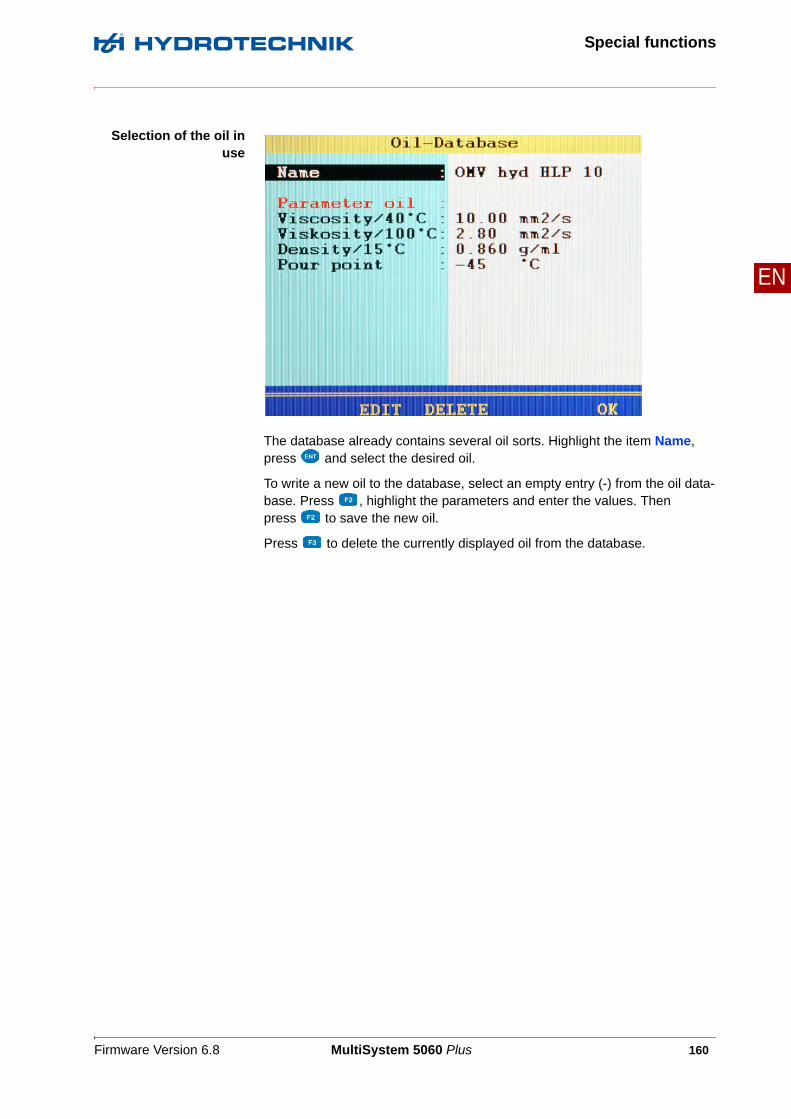
Firmware Version 6.8 MultiSystem 5060 Plus 160
Special functions
EN
Selection of the oil inuse
The database already contains several oil sorts. Highlight the item Name, press and select the desired oil.
To write a new oil to the database, select an empty entry (-) from the oil data-base. Press , highlight the parameters and enter the values. Then press to save the new oil.
Press to delete the currently displayed oil from the database.

Firmware Version 6.8 MultiSystem 5060 Plus 161
Special functions
EN
Virtual channel forviscosity calculation
If desired, you can program a virtual channel (see Chapter Configure special channels (C11 ... 24) on page 53) with the calculation VISCOSITY and enter the required parameters.
The result of the calculation will be used at the channel for volume flow rate measurement to compensate the viscosity changes dependent on the temper-ature. You may also display and record this channel.

Firmware Version 6.8 MultiSystem 5060 Plus 162
Cleaning and maintenance
EN
Cleaning and maintenance
Cleaning
• If the casing becomes dirty, wipe it with soft, slightly damp cloth.
• Any stubborn dirt can be removed with a mild household cleaning product.
Caution!
Damage to the instrument is possible!Switch the instrument off and disconnect from the power supply BEFORE starting to clean. This prevents the risk of a short-circuit, and thereby possible damage to the device.
Caution!
Damage to the instrument is possible!Do NOT use any aggressive cleaning materials, solvents, cleaning solvents or simi-lar chemicals when cleaning the device. This prevents the risk of damage to the cas-ing and/or dulling the display.

Firmware Version 6.8 MultiSystem 5060 Plus 163
Cleaning and maintenance
EN
Maintenance
This device is maintenance-free. However, it is still essential to have it recali-brated regularly. If the device is in continuous use, we recommend recalibrating it every 2 years.
HYDROTECHNIK maintains a capable calibration laboratory. Please contact us:
HYDROTECHNIK GmbH
Holzheimer Straße 94D-65549 Limburg an der Lahn
Tel.: +49 6431 4004 0Fax: +49 6431 45308
email: [email protected]: www.hydrotechnik.com
Firmware Version 6.8 MultiSystem 5060 Plus 164
Cleaning and maintenance
EN
Repair
If repair is needed, please contact our customer service department. Please have the following information ready when you contact us. If you are returning the equipment, please also attach the following information:
• Company, department, contact person
• Address, telephone and fax number, email address
• Faulty part (equipment, sensor, cable, power pack)
• PC used (CPU, operating system, RAM, HDD)
• HYDROcom software version
• Service menu print out, setting DETAIL
• Description of fault (please leave the settings on your equipment exactly as they appeared at the time of the fault/error; and please briefly describe the use of equipment, the connection of the sensors, the equipment set-up such as storage parameters, triggers, how many measurements were recorded, printer type, etc.)

Firmware Version 6.8 MultiSystem 5060 Plus 165
Cleaning and maintenance
EN
Manufacturer address and customer service
Please contact the HYDROTECHNIK customer service department:
HYDROTECHNIK GmbH
Holzheimer Straße 94D-65549 Limburg an der Lahn
Tel.: +49 6431 4004 0Fax: +49 6431 45308
email: [email protected]: www.hydrotechnik.com