Embed Size (px)
Citation preview

www.altronics.com.au
User manual revision number: 1.4 1/09/2015
Operating Manual A 4585 Zone Paging System
A 4586 Paging Console (Optional)
Redback® Proudly Made In Australia
Distributed by Altronic Distributors Pty. Ltd. Phone: 1300 780 999 Fax: 1300 790 999 Internet: www.altronics.com.au
IMPORTANT NOTE: Please read these instructions carefully from front to back prior to installation. They include
important setup instructions. Failure to follow these instructions may prevent the system from working as designed.
A 4586
A 4585

www.altronics.com.auRedback® Proudly Made In Australia2
REDBACK is a registered trademark of Altronic Distributors Pty Ltd
Since 1976 Redback amplifiers have been manufactured in Perth, Western Australia by Altronics. With over 35 years experience in the commercial audio industry, we offer consultants, installers and end users reliable products of high build quality with local product support. We believe there is significant added value for customers when purchasing an Australian made Redback amplifier or PA product
Australian Made Status
All Redback house products made by Altronics will now be sporting the official Australian Made logo. Since starting manufacturing of commercial audio equipment in the mid 70’s we have always taken pride in producing a quality local product.
The new adoption of the Australian Made logo will help us get the word out to local and export markets that our products carry the official compliance seal of the Australian Made campaign. We have always pushed our ‘local is better’ line in all of our marketing efforts, it’s always an added boost when you are backed up by a widely recognised andrespected icon.
Industry leading 10 year warranty.
There’s a reason we have the industry leading DECADE warranty. It’s because of a long tried and tested history of bulletproof reliability. We’ve heard PA contractors tell us they still see the original Redford amplifier still in service in schools - that’s over 37 years of operation - and still going strong!
Published by Altronic Distributors © 2015 Altronic Distributors

www.altronics.com.au Redback® Proudly Made In Australia 3
1.0 Overview
1.1 Introduction 4 1.2 Features 4 1.3 What’s in the box 4 1.4 Front panel guide 5 1.5 Rear panel connections 6-7
2.0 Setup
2.1 Setup Guide 7 2.2 Switching 100V Speaker Levels 8 2.2.1 Single Amplifier 100V Line Switching 8 2.2.2 Two Amplifier 100V Line Switching 92.3 Switching Line Level signals 10 2.4 Evac Inputs 11-12 2.5 24V DC Switched Output 12-13
3.0 Paging Console
3.1 A 4586 Overview 14 3.1.1 Features 15 3.1.2 DIP Switch Settings 15 3.1.3 Connecting the paging consoles 15 3.1.4 Cascading the paging consoles 16 3.1.5 Multi-zone Paging 16 3.1.6 Zone Lockout 16 3.1.7 Store and Recall Groups Of Zones 17 3.1.8 Paging Console Busy
4.0 Troubleshooting
4.1 Symptoms and Remedies 184.2 RJ45 Cabling Configuration 18
5.0 Specifications 19
6.0 A 4586 Programming Sheets 20
Contents

www.altronics.com.auRedback® Proudly Made In Australia4
WARNING System components are connected using standard “pin to pin”
configuration RJ45 data cabling. When installing ensure all connections are verified before switching any system component on.
Failure to follow the correct wiring configuration may result in damage to system components.
For the correct wiring configuration, see section 6.0 “Troubleshooting”.
Overview
1.0 OVERVIEW
1.1 INTRODUCTION
This unit is a very versatile cost effective public address/background music control system which provides audio to up to 16 zones. Background music which can be selected to play through any zone is muted when general paging occurs or when an evacuation input overrides the system.Operation is as follows:
Background music is piped to any zone which has been selected to have background music via switches on the front of the A 4585.
General Paging (via optional A 4586 paging station) will mute the background music to the zone paged or all zones depending on the setup configuration. The paging audio will then feed to the selected zones.
A 4575 RJ45 Input mutes background music to all zones. This is a vox enabled input which can be adjusted via a vox sensitivity control. The audio from the A 4575 will then feed to all zones.
Evac Input mutes background music to all zones. This input has the same priority as the A 4575 RJ45 input. This input is a vox enabled dual RCA input adjusted via a vox sensitivity control. The audio from the Evac input will then feed to all zones.
1.2 FEATURES
• 16 zone paging• Background music selectable to each zone• Evac Input• A 4575 Alert/Evac controller interface input (via CAT5E cable)• 100V or line level switching• 24V switched output• Backup battery input• Single amp or Dual amp mode• 24V DC operation. • 19” Rack Mount (2 unit).
Optional Features
• Zone and emergency over-ride paging via A 4586 paging console.
1.3 WHAT’S IN THE BOX
A 4585 Audio Switcher 24V DC 2A PlugpackUSB - PS2 compatible keyboard (Altronics D 2111)Instruction Booklet

www.altronics.com.au Redback® Proudly Made In Australia 5
Fig 1.4A shows the layout of the A 4585 front panel.
Fig 1.4A
1 Zone Background music selector switches Use these switches to turn on or off the background music to a zone.
2 Background music volume control Use this control to adjust the volume of the background music input.
3 Paging microphone volume control Use this control to adjust the volume of the paging microphone input.
4 System active indicator This led illuminates to indicate when the system is active.
5 Evac active indicator These LED illuminate to indicate when the evac input is active.
6 On indicator This led indicates the unit has power.
7 Power switch Use this to switch to turn on mains power 220-240V AC.
1.4 FRONT PANEL GUIDE
Overview
On
Power
System Active
Evac Active
Zone Background Music Selector Mic VolBGM Vol
0
2
4 6
8
10 0
2
4 6
8
10
CommunicatorA 4585
On
O�
On
O�
On
O�
On
O�
On
O�
On
O�
On
O�
On
O�
On
O�
On
O�
On
O�
On
O�
On
O�
On
O�
14
On
O�
32 164 5 151 13121110987
On
O�
6
1 2 3 4 65 7

www.altronics.com.auRedback® Proudly Made In Australia6
1.5 REAR PANEL CONNECTIONS
Fig 1.5A shows the layout of the A 4585 rear panel.
Fig 1.5A1 24V DC Input Connects to a 24V DC input with at least 1 amp current capacity. (Please observe the polarity)
2 24V Battery Backup Connect a 24V backup supply to these terminals. (Please observe the polarity)
3 DC fuse (2A M205) This fuse protects the internal power supply. Replace with 2A rated fuse only.
4 24V DC Switched Output A 24V output is provided which operates in a normally closed and normally open condition. This is activated whenever a zone is paged or when an evac input is triggered (see dip switch settings).
5 PA Out RCA Connectors Connect these outputs to the input of the paging amplifier
6 BGM Out RCA Connectors Connect these outputs to the input of the background music amplifier
7 BGM In RCA Connectors Connect these inputs to the output of the background music source such as a CD player. 8 Evac In RCA Connectors Connect these inputs to the output of an evacuation tone generator.
9 Emergency input Vox Level Use this trimpot adjustment to change the vox level for the emergency input.
10 A 4575 RJ45 input Use this input to connect to the output of the A 4575 Alert/Evac controller.
11 RJ45 connectors for paging consoles These RJ45 ports connect to the A 4586 zone paging consoles. NOTE: A maximum of two A 4586 microphone paging consoles may be connected to each port.
Manufactured in Australia By Altronic Distributors Pty. Ltd.
From BGM AMP
L
R
L
R
BGM Out
24V Switched
Out
N/O
DC FUSE
(1A M205)
From24V
BATTERY24V DC
IN
A 4575 Input
N/C
From PA
AMPZones
1 2 3 4 5 6 7 8
1
Paging Stations3 4
1 2
+ - + -
2345678910111213141516
100V Switching - 1 AMP SYSTEM - Connect PA amp 100V output to “From PA AMP” Terminals2 AMP SYSTEM - Connect PA amp 100V output to “From PA AMP” terminals and BGM amp 100V ouput to “From BGM AMP terminals. Connect Zone ampli�er speakers to ”+” and “-” terminals.
Connect Zone ampli�er line level inputs to “+” , ” - ” and “ ” terminals.Preamp Switching -
DIP Switch SettingsSW12
3-8
On O�Single Amp Mode
Not Used
Dual Amp ModeLine Level Speaker Level
+- +- +- +- +- +- +- +-+-+-+-+-+ - - ++- - +www.altronics.com.au
+ +_ _ PA Out BGM Input Evac InputEvac Vox
Sensitivity+ _ + _
1 2 3 4 5 6 7 8
15
1 2 3 4 5 6 7 8 9 10 11 12
1314
Overview

www.altronics.com.au Redback® Proudly Made In Australia 7
Overview
2.0 SETUP
2.1 Setup Guide The A 4585 is a 16 zone paging system which switches 100V speaker levels or balanced low level (line levels) signals. Background music which can be piped to any zone is muted when paging is initiated by the A 4586 paging consoles or when the Evac input is triggered.
WARNING : For correct operation the dip switches 1 & 2 need to be set before using the unit.
If the A 4585 is being used in single amplifier mode (see section 2.2.1) dip switch 1 must be set to “ON”otherwise if the unit is being used in two amplifer mode (see section 2.2.2) then dip switch 1 must be set to “OFF”
When using the unit for 100V speaker switching Dip switch 2 must be set to “OFF”.If line level switching is required then Dip Switch 2 must be set to “ON”.
Failure to set the dip switches correctly might result in the unit malfunctioning.
Fig 1.6A
12 Dip Switch Settings Fig 1.6A shows the settings available. DIP switch 1 sets set the amplifier mode, either single amp or dual amp mode. (see section 2.2 for more details) DIP switch 2 sets the output level, either line level or 100V speaker level. (see section 2.2 for more details) DIP switch 3 sets the 24V DC switched output configuration. This can be set to operate when any zone is triggered or for Evac triggering. (see section 2.5 for more details)
DIP switches 4-8 are not used.
DIP Switch SettingsSW12
3
On O�Single Amp Mode
24V DC Output EVAC trigger only
Dual Amp ModeLine Level Speaker Level
4-8
24V DC Output any zone trigger
NOT USED
13 From BGM AMP input Connect this 100V line input from the 100V output of the BGM (background music) amplifier.
14 From PA AMP input Connect this 100V line input from the 100V output of the PA (or paging) amplifier.
15 Zone 1-16 outputs. The zone outputs can be either 100V or line level depending on configuration of the dip switches (see Fig1.6A)

www.altronics.com.auRedback® Proudly Made In Australia8
Setup Guide
2.2 SWITCHING 100V SPEAKER LEVELS
There are two different configurations for switching 100V speaker levels. The first uses a single amp system which is used for both Background music and PA paging. This setup mutes background music to “ALL” zones when any zone is paged.(see section 2.2.1)
The second setup involves a two amplifier system where both the background music and the PA paging has its own dedi-cated amplifier. This setup mutes background music to only those zones which are being paged. (See section 2.2.2)
2.2.1 SINGLE AMPLIFIER 100V LINE SWITCHING
A single amp system uses one amplifier which is used for both the background music and the PA paging. In this configura-tion when any zone or zones is paged the background music will be muted to all zones. (Note: If muting is desired for only those zones being paged a two amplifier setup is required (See section 2.2.2)).
NOTE : Before turning the unit on make sure the dip switches are set correctly.For single amp switching of 100V speaker levels, Dip switch 1 should be set to “ON”
and dip switch 2 should be set to “OFF” (see Dip switch settings Fig 1.6)
Each zone requiring background music must be switched “ON” from the “Zone Background Music Selector” switches on the front of the A 4585. (refer to section 1.4)
A background music source such as a CD player is connected to the BGM input (RCA connectors) on the rear of the A 4585. The amplifier audio connection is from the “PA Out” RCA sockets on the rear of the A 4585. This is a line level signal and must be connected to a Line/Aux input on the amplifier.The amplifier 100V output must be connected to the “From PA AMP” terminals on the rear of the A 4585.The zone 100V speakers are wired to the “+” and “-” terminals only on the rear of the A 4585 as shown in Fig 2.2A. (Note: the earth connection is not used for 100V switching system. This terminal is used when switching line level signals.)
Fig 2.1
Manufactured in Australia By Altronic Distributors Pty. Ltd.
From BGM AMP
L
R
L
R
BGM Out
24V Switched
Out
N/O
DC FUSE
(1A M205)
From24V
BATTERY24V DC
IN
A 4575 Input
N/C
From PA
AMPZones
1 2 3 4 5 6 7 8
1
Paging Stations3 4
1 2
+ - + -
2345678910111213141516
100V Switching - 1 AMP SYSTEM - Connect PA amp 100V output to “From PA AMP” Terminals2 AMP SYSTEM - Connect PA amp 100V output to “From PA AMP” terminals and BGM amp 100V ouput to “From BGM AMP terminals. Connect Zone ampli�er speakers to ”+” and “-” terminals.
Connect Zone ampli�er line level inputs to “+” , ” - ” and “ ” terminals.Preamp Switching -
DIP Switch SettingsSW12
3-8
On O�Single Amp Mode
Not Used
Dual Amp ModeLine Level Speaker Level
+- +- +- +- +- +- +- +-+-+-+-+-+ - - ++- - +www.altronics.com.au
+ +_ _ PA Out BGM Input Evac InputEvac Vox
Sensitivity+ _ +_
BGM (Background Music Source)
Line Input 100V Output
Connect to“From PA AMP”
terminals
Single Ampli�er 100V Line Switching
Speakers to be paged must be �tted with 100V line transformers.Connect using the “+” and “-”
terminals. (Do not use the “ ” terminal) Zone 16
1 2 3 4 5 6 7 8
CD
REDBACK
POWER
REDBACK A 4270 125WPublic Address Ampli�ePHASE5
100V LINE AMPLIFIER
A 4586 Paging Console
CAT5 cable (Max 300 Metres)
Zone 15
Zone 14
Zone 13
Zone 12
Zone 11
Zone 10
Zone 9
Zone 8
Zone 7
Zone 6
Zone 5
Zone 4
Zone 3
Zone 2
Zone 1
Store
Recall
All Call
Cancel
A 4586 Communicator
System Busy
Page
Lock OnREDBACK A 4586
8 Zone Communicator
Version 1.1

www.altronics.com.au Redback® Proudly Made In Australia 9
Setup Guide
2.2.2 TWO AMPLIFIER 100V LINE SWITCHING
A two amplifier system uses dedicated amplifiers for both the background music and the PA paging. This setup mutes background music to only those zones which are being paged.
NOTE : Before turning the unit on make sure the dip switches are set correctly.For two amp switching of 100V speaker levels, Dip switch 1 should be set to “OFF”
and dip switch 2 should be set to “OFF” (see Dip switch settings Fig 1.6)
Each zone requiring background music must be switched “ON” from the “Zone Background Music Selector” switches on the front of the A 4585. (refer to section 1.4)
A background music source such as a CD player is connected to the BGM input (RCA connectors) on the rear of the A 4585.
Paging Amplifier ConnectionsThe paging amplifier audio connection is from the “PA Out” RCA sockets on the rear of the A4585. This is a line level signal and must be connected to a Line/Aux input on the amplifier.The paging amplifier 100V output must be connected to the “From PA AMP” terminals on the rear of the A 4585.
Background Music Amplifier ConnectionsThe background music amplifier audio connection is from the “BGM Out” RCA sockets on the rear of the A 4585. This is a line level signal and must be connected to a Line/Aux input on the amplifier.The background music amplifier 100V output must be connected to the “From BGM AMP” terminals on the rear of the A 4585.
The zone 100V speakers are wired to the “+” and “-” terminals only on the rear of the A 4585 as shown in Fig 2.2A. (Note: the earth connection is not used for 100V switching system. This terminal is used when switching line level signals.)
Fig 2.2
Manufactured in Australia By Altronic Distributors Pty. Ltd.
From BGM AMP
L
R
L
R
BGM Out
24V Switched
Out
N/O
DC FUSE
(1A M205)
From24V
BATTERY24V DC
IN
A 4575 Input
N/C
From PA
AMPZones
1 2 3 4 5 6 7 8
1
Paging Stations3 4
1 2
+ - + -
2345678910111213141516
100V Switching - 1 AMP SYSTEM - Connect PA amp 100V output to “From PA AMP” Terminals2 AMP SYSTEM - Connect PA amp 100V output to “From PA AMP” terminals and BGM amp 100V ouput to “From BGM AMP terminals. Connect Zone ampli�er speakers to ”+” and “-” terminals.
Connect Zone ampli�er line level inputs to “+” , ” - ” and “ ” terminals.Preamp Switching -
DIP Switch SettingsSW12
3-8
On O�Single Amp Mode
Not Used
Dual Amp ModeLine Level Speaker Level
+- +- +- +- +- +- +- +-+-+-+-+-+ - - ++- - +www.altronics.com.au
+ +_ _ PA Out BGM Input Evac InputEvac Vox
Sensitivity+ _ +_
BGM (Background Music Source)
Line Input
100V Output
Connect to“From PA AMP”
terminals
Two Ampli�er 100V Line Switching
Speakers to be paged must be �tted with 100V line transformers.Connect using the “+” and “-”
terminals. (Do not use the “ ” terminal) Zone 16
1 2 3 4 5 6 7 8
CD
REDBACK
POWER
REDBACK A 4270 125WPublic Address Ampli�ePHASE5
100V LINE PAGING AMPLIFIER
A 4586 Paging Console
CAT5 cable (Max 300 Metres)
Zone 15
Zone 14
Zone 13
Zone 12
Zone 11
Zone 10
Zone 9
Zone 8
Zone 7
Zone 6
Zone 5
Zone 4
Zone 3
Zone 2
Zone 1
Line Input
100V OutputPOWER
REDBACK A 4270 125WPublic Address Ampli�ePHASE5
100V LINE BACKGROUND MUSIC AMPLIFIER
Store
Recall
All Call
Cancel
A 4586 Communicator
System Busy
Page
Lock OnREDBACK A 4586
8 Zone Communicator
Version 1.1

www.altronics.com.auRedback® Proudly Made In Australia10
2.3 SWITCHING LINE LEVELS
The A 4585 can also be used to switch line level signals. Amplifiers are not connected to the PA OUT or BGM OUT of the A 4585. Instead each zone has its own dedicated amplifer which can then feed multiple areas. Background music and the evacuation tones are still supplied by the A 4585 and are fed into each zone amplifier. Each zone amplifier can still have its own local microphone or background music.
NOTE : Before turning the unit on make sure the dip switches are set correctly. Dip switch 2 should be set to “ON” (see Dip switch settings Fig 1.6)
Dip switch 1 will be disabled if dip switch 2 is set to “ON”
This setup mutes the background music (supplied by the A 4585) to only those zones which are being paged.
Each zone requiring background music must be switched “ON” from the “Zone Background Music Selector” switches on the front of the A 4585. (refer to section 1.4)A background music source such as a CD player is connected to the BGM input (RCA connectors) on the rear of the A 4585.
The zone output terminals on the rear of the A 4585 are connected to the zone amplifier inputs. The “+”,”-” and earth terminals are all used. Each zone output is a low impedance signal suitable for feeding directly into a power amplifier. As the signal is balanced the amplifier can be remotely located when connected using 2 core shielded cable. This enables the amplifier to be located up to 100m from the A 4585 switch box.
Fig 2.3
Setup Guide
Manufactured in Australia By Altronic Distributors Pty. Ltd.
From BGM AMP
L
R
L
R
BGM Out
24V Switched
Out
N/O
DC FUSE
(1A M205)
From24V
BATTERY24V DC
IN
A 4575 Input
N/C
From PA
AMPZones
1 2 3 4 5 6 7 8
1
Paging Stations3 4
1 2
+ - + -
2345678910111213141516
100V Switching - 1 AMP SYSTEM - Connect PA amp 100V output to “From PA AMP” Terminals2 AMP SYSTEM - Connect PA amp 100V output to “From PA AMP” terminals and BGM amp 100V ouput to “From BGM AMP terminals. Connect Zone ampli�er speakers to ”+” and “-” terminals.
Connect Zone ampli�er line level inputs to “+” , ” - ” and “ ” terminals.Preamp Switching -
DIP Switch SettingsSW12
3-8
On O�Single Amp Mode
Not Used
Dual Amp ModeLine Level Speaker Level
+- +- +- +- +- +- +- +-+-+-+-+-+ - - ++- - +www.altronics.com.au
+ +_ _ PA Out BGM Input Evac InputEvac Vox
Sensitivity+ _ +_
BGM (Background Music Source)
100V Output
Individual Zone Ampli�er Preamp (Low Level) Switching
LOCAL MIC
+-
Output connector con�guration for
each zone.
Hot
Cold
Eart
h
1 2 3 4 5 6 7 8
CD
REDBACK
POWER
REDBACK A 4270 125WPublic Address Ampli�ePHASE5
ZONE 1 AMPLIFIER
A 4586 Paging Console
CAT5 cable (Max 300 Metres)
100V OutputLOCAL MIC
POWER
REDBACK A 4270 125WPublic Address Ampli�ePHASE5
ZONE 8 AMPLIFIER
100V Output
LOCAL MIC
POWER
REDBACK A 4270 125WPublic Address Ampli�ePHASE5
ZONE 16 AMPLIFIER
100V Output
LOCAL MIC
POWER
REDBACK A 4270 125WPublic Address Ampli�ePHASE5
ZONE 9 AMPLIFIER
CD
REDBACK LOCAL BGM
CD
REDBACK LOCAL BGM
CD
REDBACK LOCAL BGM
CD
REDBACK LOCAL BGM
Store
Recall
All Call
Cancel
A 4586 Communicator
System Busy
Page
Lock OnREDBACK A 4586
8 Zone Communicator
Version 1.1

www.altronics.com.au Redback® Proudly Made In Australia 11
2.4 EVAC INPUTS
There are two forms of evacuation inputs available on the A 4585.
A 4575 RJ45 Input The first is made via an RJ45 connection on the back of the unit which feeds directly from the A 4575 Alert/Evacuation controller (see Fig 2.4a). A CAT5e cable connected between the two units pipes in the evac audio from the A 4575. The trigger level is adjusted via the evac vox sensitivity control of the back of the A 4585. Once the evac input is triggered, background music will be muted to all zones. Paging from an A 4586 paging console will over-ride the evac input.When the evac input is active the “Evac active” led on the front of the unit will illuminate.
Fig 2.4a
Setup Guide
Evac Input (Dual RCA)The second type of evac input is in the form of a dual RCA audio input on the rear of the unit labelled Evac Input (see Fig 2.4b). The trigger level is adjusted via the evac vox sensitivity control of the back of the A 4585. Once the evac input is triggered, background music will be muted to all zones. Paging from an A 4586 paging console will over-ride the evac input. When the evac input is active the “Evac active” led on the front of the unit will illuminate.Note: This could also be used for ALL CALL telephone paging when used with a suitable Line Isolation Unit.
Manufactured in Australia By Altronic Distributors Pty. Ltd.
From BGM AMP
L
R
L
R
BGM Out
24V Switched
Out
N/O
DC FUSE
(1A M205)
From24V
BATTERY24V DC
IN
A 4575 Input
N/C
From PA
AMPZones
1 2 3 4 5 6 7 8
1
Paging Stations3 4
1 2
+ - + -
2345678910111213141516
100V Switching - 1 AMP SYSTEM - Connect PA amp 100V output to “From PA AMP” Terminals2 AMP SYSTEM - Connect PA amp 100V output to “From PA AMP” terminals and BGM amp 100V ouput to “From BGM AMP terminals. Connect Zone ampli�er speakers to ”+” and “-” terminals.
Connect Zone ampli�er line level inputs to “+” , ” - ” and “ ” terminals.Preamp Switching -
DIP Switch SettingsSW12
3-8
On O�Single Amp Mode
Not Used
Dual Amp ModeLine Level Speaker Level
+- +- +- +- +- +- +- +-+-+-+-+-+ - - ++- - +www.altronics.com.au
+ +_ _ PA Out BGM Input Evac InputEvac Vox
Sensitivity+ _ +_
EVACUATION INPUT TRIGGERING VIA A 4575 ALERT/EVAC CONTROLLER
+ _1 2 3 4 5 6 7 8
1 2 3 4 5 6 7 8
A 4586 Paging Console
CAT5e cable (Max 300 Metres)
CAT5e cable (Max 300 Metres)
A 4585 COMMUNICATOR
A 4575 ALERT/EVAC CONTROLLER
Evac input vox sensitivityset by this trimpot.
NOTE : The A 4575 input is to be connectedonly to an A 4575 Alert/Evac Controller
Store
Recall
All Call
Cancel
A 4586 Communicator
System Busy
Page
Lock OnREDBACK A 4586
8 Zone Communicator
Version 1.1
www.altronics.com.auRedback® Proudly Made In Australia12
Setup Guide
Fig 2.4b
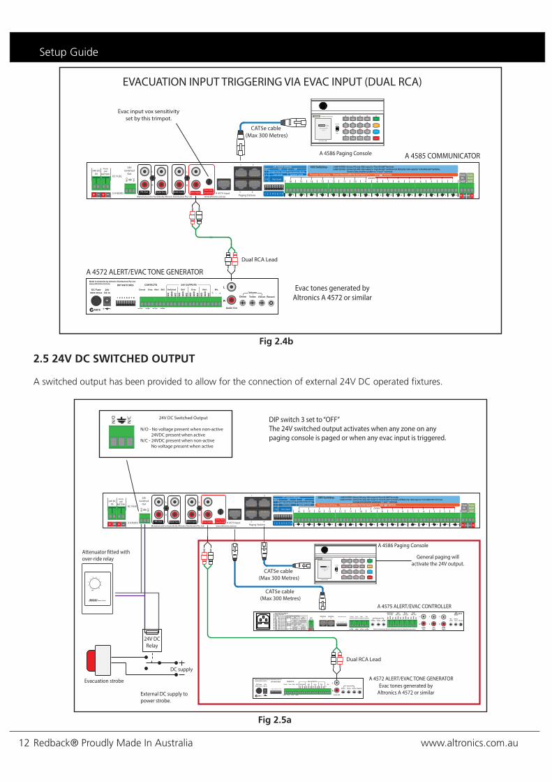
2.5 24V DC SWITCHED OUTPUT
A switched output has been provided to allow for the connection of external 24V DC operated fixtures.
Fig 2.5a
Manufactured in Australia By Altronic Distributors Pty. Ltd.
From BGM AMP
L
R
L
R
BGM Out
24V Switched
Out
N/O
DC FUSE
(1A M205)
From24V
BATTERY24V DC
IN
A 4575 Input
N/C
From PA
AMPZones
1 2 3 4 5 6 7 8
1
Paging Stations3 4
1 2
+ - + -
2345678910111213141516
100V Switching - 1 AMP SYSTEM - Connect PA amp 100V output to “From PA AMP” Terminals2 AMP SYSTEM - Connect PA amp 100V output to “From PA AMP” terminals and BGM amp 100V ouput to “From BGM AMP terminals. Connect Zone ampli�er speakers to ”+” and “-” terminals.
Connect Zone ampli�er line level inputs to “+” , ” - ” and “ ” terminals.Preamp Switching -
DIP Switch SettingsSW12
3-8
On O�Single Amp Mode
Not Used
Dual Amp ModeLine Level Speaker Level
+- +- +- +- +- +- +- +-+-+-+-+-+ - - ++- - +www.altronics.com.au
+ +_ _ PA Out BGM Input Evac InputEvac Vox
Sensitivity+ _ +_
EVACUATION INPUT TRIGGERING VIA EVAC INPUT (DUAL RCA)
1 2 3 4 5 6 7 8
A 4586 Paging Console
CAT5e cable (Max 300 Metres)
A 4585 COMMUNICATOR
Evac input vox sensitivityset by this trimpot.
Made In Australia by Altronic Distributors Pty Ltd. www.altronics.com.au
DC FuseM205 500mA
N816
24V DC In
L
R
Audio Out
V/OverTonesChime
Volume
Record1 2 3 4 5 6 7 8
Mic
+-
N/O
GN
D
N/C
Switched
N/O
GN
D
N/C
N/O
GN
D
N/C
N/O
GN
D
N/C
24V OUTPUTS
Bell Evac AlertBellAlertEvacCancel
CONTACTSDIP SWITCHES
+ -1 2 3 4 5 6 7 8
Dual RCA Lead
A 4572 ALERT/EVAC TONE GENERATOR
Evac tones generated by Altronics A 4572 or similar
Store
Recall
All Call
Cancel
A 4586 Communicator
System Busy
Page
Lock OnREDBACK A 4586
8 Zone Communicator
Version 1.1
Manufactured in Australia By Altronic Distributors Pty. Ltd.
From BGM AMP
L
R
L
R
BGM Out
24V Switched
Out
N/O
DC FUSE
(1A M205)
From24V
BATTERY24V DC
IN
A 4575 Input
N/C
From PA
AMPZones
1 2 3 4 5 6 7 8
1
Paging Stations3 4
1 2
+ - + -
2345678910111213141516
100V Switching - 1 AMP SYSTEM - Connect PA amp 100V output to “From PA AMP” Terminals2 AMP SYSTEM - Connect PA amp 100V output to “From PA AMP” terminals and BGM amp 100V ouput to “From BGM AMP terminals. Connect Zone ampli�er speakers to ”+” and “-” terminals.
Connect Zone ampli�er line level inputs to “+” , ” - ” and “ ” terminals.Preamp Switching -
DIP Switch SettingsSW12
3-8
On O�Single Amp Mode
Not Used
Dual Amp ModeLine Level Speaker Level
+- +- +- +- +- +- +- +-+-+-+-+-+ - - ++- - +www.altronics.com.au
+ +_ _ PA Out BGM Input Evac InputEvac Vox
Sensitivity+ _ +_
1 2 3 4 5 6 7 8
24V DC Switched Output
N/O - No voltage present when non-active 24VDC present when activeN/C - 24VDC present when non-active No voltage present when active
N/C
N/O
Made In Australia by Altronic Distributors Pty Ltd. www.altronics.com.au
DC FuseM205 500mA
N816
24V DC In
L
R
Audio Out
V/OverTonesChime
Volume
Record1 2 3 4 5 6 7 8
Mic
+-
N/O
GN
D
N/C
Switched
N/O
GN
D
N/C
N/O
GN
D
N/C
N/O
GN
D
N/C
24V OUTPUTS
Bell Evac AlertBellAlertEvacCancel
CONTACTSDIP SWITCHES
+ -1 2 3 4 5 6 7 8
Dual RCA Lead
A 4572 ALERT/EVAC TONE GENERATOR
+ _1 2 3 4 5 6 7 8
CAT5e cable (Max 300 Metres)
A 4575 ALERT/EVAC CONTROLLER
A 4586 Paging Console
DIP switch 3 set to “OFF” The 24V switched output activates when any zone on any paging console is paged or when any evac input is triggered.
CAT5e cable (Max 300 Metres)
Evac tones generated by Altronics A 4572 or similar
Attenuator �tted withover-ride relay
Evacuation strobe
DC supply
24V DCRelay
External DC supply topower strobe.
General paging willactivate the 24V output.
Store
Recall
All Call
Cancel
A 4586 Communicator
System Busy
Page
Lock OnREDBACK A 4586
8 Zone Communicator
Version 1.1
www.altronics.com.au Redback® Proudly Made In Australia 13
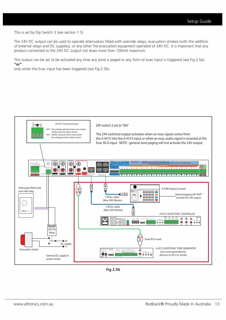
Fig 2.5b
Setup Guide
This is set by Dip Switch 3 (see section 1.5)
The 24V DC output can be used to operate attenuators fitted with override relays, evacuation strobes (with the addition of external relays and DC supplies), or any other fire evacuation equipment operated of 24V DC. It is important that any product connected to the 24V DC output not draw more than 100mA maximum.
This output can be set to be activated any time any zone is paged or any form of evac input is triggered (see Fig 2.5a).“or”only when the Evac input has been triggered (see Fig 2.5b).
Manufactured in Australia By Altronic Distributors Pty. Ltd.
From BGM AMP
L
R
L
R
BGM Out
24V Switched
Out
N/O
DC FUSE
(1A M205)
From24V
BATTERY24V DC
IN
A 4575 Input
N/C
From PA
AMPZones
1 2 3 4 5 6 7 8
1
Paging Stations3 4
1 2
+ - + -
2345678910111213141516
100V Switching - 1 AMP SYSTEM - Connect PA amp 100V output to “From PA AMP” Terminals2 AMP SYSTEM - Connect PA amp 100V output to “From PA AMP” terminals and BGM amp 100V ouput to “From BGM AMP terminals. Connect Zone ampli�er speakers to ”+” and “-” terminals.
Connect Zone ampli�er line level inputs to “+” , ” - ” and “ ” terminals.Preamp Switching -
DIP Switch SettingsSW12
3-8
On O�Single Amp Mode
Not Used
Dual Amp ModeLine Level Speaker Level
+- +- +- +- +- +- +- +-+-+-+-+-+ - - ++- - +www.altronics.com.au
+ +_ _ PA Out BGM Input Evac InputEvac Vox
Sensitivity+ _ +_
1 2 3 4 5 6 7 8
24V DC Switched Output
N/O - No voltage present when non-active 24VDC present when activeN/C - 24VDC present when non-active No voltage present when active
N/C
N/O
Made In Australia by Altronic Distributors Pty Ltd. www.altronics.com.au
DC FuseM205 500mA
N816
24V DC In
L
R
Audio Out
V/OverTonesChime
Volume
Record1 2 3 4 5 6 7 8
Mic
+-
N/O
GN
D
N/C
Switched
N/O
GN
D
N/C
N/O
GN
D
N/C
N/O
GN
D
N/C
24V OUTPUTS
Bell Evac AlertBellAlertEvacCancel
CONTACTSDIP SWITCHES
+ -1 2 3 4 5 6 7 8
Dual RCA Lead
A 4572 ALERT/EVAC TONE GENERATOR
+ _1 2 3 4 5 6 7 8
CAT5e cable (Max 300 Metres)
A 4575 ALERT/EVAC CONTROLLER
A 4586 Paging Console
CAT5e cable (Max 300 Metres)
DIP switch 3 set to “ON” The 24V switched output activates when an evac signal comes from the A 4575 into the A 4575 input or when an evac audio signal is received at theEvac RCA input . NOTE : general zone paging will not activate the 24V output.
Evac tones generated by Altronics A 4572 or similar
Attenuator �tted withover-ride relay
Evacuation strobe
DC supply
24V DCRelay
External DC supply topower strobe.
Store
Recall
All Call
Cancel
A 4586 Communicator
System Busy
Page
Lock OnREDBACK A 4586
8 Zone Communicator
Version 1.1
General paging will “NOT”activate the 24V output.

www.altronics.com.auRedback® Proudly Made In Australia14
3.0 PAGING CONSOLES
3.1 A 4586 OVERVIEW
The A 4586 paging console provides up to 16 zones of paging to the A 4585 audio switcher.
The consoles can be used for multi zone paging with the facility to store and recall multiple zones to a single button. The recall functions can also be labelled via a USB - PS2 compatible keyboard which can be plugged into the rear of the unit. (see section 3.1.7) The labels will then be displayed on the highly functional and attractive LCD. An example might be a label “sales”.
An emergency paging over-ride facility is accessed by a combination of an illuminated push button switch and a PTT (push to talk) switch. This combination removes the possibliity of accidentally activating the emergency over-ride facility. When activated, emergency paging will be forced through to all zones.
A maximum of 8 paging consoles can be connected to the A 4585 at the same time. These work in a “first in, best dressed” arrangement. The consoles can be cascaded together or wired back to the A 4585 (see section 3.1.3 to 3.1.5 for details).
Each unit must be assigned an ID number through DIP switch settings on the rear of the unit. A pre-announcement chime is available at the paging console and through the PA system. Both of these are set by DIP switches on the rear of the unit.
1 24V DC connector 2.1mm DC jack (centre pin positive).
2 RJ45 connector For connection back to the A 4585.
3 Cascade paging connector Secondary RJ45 socket for cascading a second console.
4 USB keyboard input. Use the keyboard to record labels for saved store functions.
5 Microphone volume Use this volume to adjust the microphone level.
6 Chime volume Use this volume to adjust the chime level.
7 DIP switch options These switches set the chime and emergency paging on or off and also assign a location number or ID to the console.
Fig 3.1A
Paging Console
www.altronics.com.auManufactured in Australia By Altronic Distributors Pty. Ltd.
24VDC In VolumeMicTo Main Unit To 2nd Console ChimeUSB
Keyboard(Must be PS2 Compatible)
Volume
1 2 3 4 5 6 7 8
123
PA System Chime OnSW
PA System Chime O�Internal Chime On Internal Chime O�Emergency Paging On Emergency Paging O� 6 7 8
DIP Switches 6-8Set the Paging
O� O� O�
Console IDID
On O� O�
On On O�
O� On O�O� O� On
On O� On
On On On
O� On On
78
On O�DIP Switches 1-3 Settings
123456
45
SWNot UsedNot Used
ON
1 2 3 4
ON
1 2 3 4
1 2 3 4 5 6 7

www.altronics.com.au Redback® Proudly Made In Australia 15
Paging Console
3.1.1 Features
• Multi zone paging. • Recall multiple zones with a single button press. • Keyboard entry labelling of recall zones. • LCD for indicating zone selections. • Pre-announcement chime. • Emergency override paging to all zones.
3.1.2 DIP Switch Settings
A series of DIP switches which are accessed on the rear of the unit provide a number of options. DIP switch 1 sets the PA system chime on or off. DIP switch 2 sets the internal chime on or off.DIP switch 3 sets the emergency paging on or off. (Note: The emergency paging is only active when the A 4585 receives external emergency tones).DIP switches 4&5 are not used.DIP switches 6-8 select the ID number for the console. Table 3.1A shows the ID settings.
A maximum number of 8 consoles can be connected to the A 4585.
3.1.3 Connecting the paging consoles
The consoles are connected to the A 4585 via standard Cat5e cabling as shown in Fig 3.1b. The maximum distance between the A 4585 and a paging console is 300m. Note that each paging console must be assigned an ID number via the DIP switches on the rear of the unit before operation (see 3.1.2 DIP switch settings). Eg Console 1 is set to ID1, console 2 is set to ID2 etc A maximum of eight consoles can be connected at one time but only used in certain configurations. There are four RJ45 ports on the back of the A 4585 which can be used to connect the A 4586 paging consoles. Each port can accomodate a maximum of 1 paging console without the aid of external power supplies. Fig 3.1B shows how to connect one paging console per RJ45 port.
Fig 3.1B
Table 3.1A
Manufactured in Australia By Altronic Distributors Pty. Ltd.
From BGM AMP
L
R
L
R
BGM Out
24V Switched
Out
N/O
DC FUSE
(1A M205)
From24V
BATTERY24V DC
IN
A 4575 Input
N/C
From PA
AMPZones
1 2 3 4 5 6 7 8
1
Paging Stations3 4
1 2
+ - + -
2345678910111213141516
100V Switching - 1 AMP SYSTEM - Connect PA amp 100V output to “From PA AMP” Terminals2 AMP SYSTEM - Connect PA amp 100V output to “From PA AMP” terminals and BGM amp 100V ouput to “From BGM AMP terminals. Connect Zone ampli�er speakers to ”+” and “-” terminals.
Connect Zone ampli�er line level inputs to “+” , ” - ” and “ ” terminals.Preamp Switching -
DIP Switch SettingsSW12
3-8
On O�Single Amp Mode
Not Used
Dual Amp ModeLine Level Speaker Level
+- +- +- +- +- +- +- +-+-+-+-+-+ - - ++- - +www.altronics.com.au
+ +_ _ PA Out BGM Input Evac InputEvac Vox
Sensitivity+ _ +_
1 2 3 4 5 6 7 8
A 4586 Paging Console
CAT5e cable (Max 300 Metres)
A 4585 COMMUNICATORA 4586 Paging Console
CAT5e cable (Max 300 Metres)
CAT5e cable (Max 300 Metres)
CAT5e cable (Max 300 Metres)
A 4586 Paging Console A 4586 Paging Console
PLEASE NOTE : A MAXIMUM OF 4 PAGING CONSOLES CAN BE CONNECTED TO THE A 4585 WITHOUT THE USE OF EXTERNAL POWER SUPPLIES. (AND A MAXIMUM OF 1 PAGING CONSOLE PER PORT)
Store
Recall
All Call
Cancel
A 4586 Communicator
System Busy
Page
Lock OnREDBACK A 4586
8 Zone Communicator
Version 1.1
Store
Recall
All Call
Cancel
A 4586 Communicator
System Busy
Page
Lock OnREDBACK A 4586
8 Zone Communicator
Version 1.1
Store
Recall
All Call
Cancel
A 4586 Communicator
System Busy
Page
Lock OnREDBACK A 4586
8 Zone Communicator
Version 1.1
Store
Recall
All Call
Cancel
A 4586 Communicator
System Busy
Page
Lock OnREDBACK A 4586
8 Zone Communicator
Version 1.1
6 7 8
DIP Switches 6-8Set the Paging
O� O� O�
Console IDID
On O� O�
On On O�
O� On O�O� O� On
On O� On
On On On
O� On On
78
123456

www.altronics.com.auRedback® Proudly Made In Australia16
3.1.4 Cascading the paging consoles
If more than 4 paging consoles are required the consoles can be cascaded together with the addition of external power supplies. Fig 3.1C shows how to connect eight paging consoles at once. Consoles 1-4 are connected to their respective number ports. Ie console 1 to port 1, console 2 to port 2 etc. Any extra consoles are connected as shown in Fig 3.1C, so console 5 to port 1, console 6 to port 2 and so on.Note that each paging console must be assigned an ID number via the DIP switches on the rear of the unit before operation (see 3.1.2 DIP switch settings). Eg Console 1 is set to ID1, console 2 is set to ID2 etcIn Fig 3.1C a maximum of eight consoles are connected. Consoles 1 & 5 are connected to Port 1, consoles 2 & 6 to port 2, consoles 3 & 7 to port 3 and consoles 4 & 8 are connected to Port 4. Please note: A maximum of 2 paging consoles can be connected per RJ45 port on the A 4585. Each additional paging console has a dedicated power supply and the Cat5e cable run can be no longer than 300m.
Fig 3.1C
3.1.5 Multi-zone paging Paging is achieved by pressing the numbered button of the zone required. The button will illuminate. Hold down the page switch and speak into the microphone. Note: a zone with a fast flashing LED has general paging blocked. To page to multiple zones, press the buttons for the desired zones. Multiple buttons will illuminate. Hold down the page switch and speak into the microphone.
3.1.6 Zone LockoutGeneral paging can be blocked to any zones via the paging console. To block paging to a zone from the A 4586, hold down the desired zone button until a message on the LCD indicates the zone is blocked out. Release the button to resume. To unlock the zone, repeat the procedure. NOTE: This will only lock out zones for use from the console that the zones were locked out from. It will not lock out the same zones from other paging consoles.
Paging Console
Manufactured in Australia By Altronic Distributors Pty. Ltd.
From BGM AMP
L
R
L
R
BGM Out
24V Switched
Out
N/O
DC FUSE
(1A M205)
From24V
BATTERY24V DC
IN
A 4575 Input
N/C
From PA
AMPZones
1 2 3 4 5 6 7 8
1
Paging Stations3 4
1 2
+ - + -
2345678910111213141516
100V Switching - 1 AMP SYSTEM - Connect PA amp 100V output to “From PA AMP” Terminals2 AMP SYSTEM - Connect PA amp 100V output to “From PA AMP” terminals and BGM amp 100V ouput to “From BGM AMP terminals. Connect Zone ampli�er speakers to ”+” and “-” terminals.
Connect Zone ampli�er line level inputs to “+” , ” - ” and “ ” terminals.Preamp Switching -
DIP Switch SettingsSW12
3-8
On O�Single Amp Mode
Not Used
Dual Amp ModeLine Level Speaker Level
+- +- +- +- +- +- +- +-+-+-+-+-+ - - ++- - +www.altronics.com.au
+ +_ _ PA Out BGM Input Evac InputEvac Vox
Sensitivity+ _ +_
1 2 3 4 5 6 7 8
CAT5e cable (Max 300 Metres)
CAT5e cable (Max 300 Metres)
CAT5e cable (Max 300 Metres)
CAT5e cable (Max 300 Metres)
PLEASE NOTE : A MAXIMUM OF 8 PAGING CONSOLES CAN BE CONNECTED TO THE A 4585 WITH THE USE OF EXTERNAL POWER SUPPLIES. (AND A MAXIMUM OF 2 PAGING CONSOLES PER PORT)
CONSOLE 1
CONSOLE 5
M 9391A 24V DC 1A Power Supply
M 9391A 24V DC 1A Power Supply
CAT5e cable (Max 300 Metres)
CAT5e cable (Max 300 Metres)
CONSOLE 2
CONSOLE 6
CONSOLE 8
CONSOLE 4
CONSOLE 7
CONSOLE 3
M 9391A 24V DC 1A Power Supply
M 9391A 24V DC 1A Power Supply
Store
Recall
All Call
Cancel
A 4586 Communicator
System Busy
Page
Lock OnREDBACK A 4586
8 Zone Communicator
Version 1.1
Store
Recall
All Call
Cancel
A 4586 Communicator
System Busy
Page
Lock OnREDBACK A 4586
8 Zone Communicator
Version 1.1
Store
Recall
All Call
Cancel
A 4586 Communicator
System Busy
Page
Lock OnREDBACK A 4586
8 Zone Communicator
Version 1.1
Store
Recall
All Call
Cancel
A 4586 Communicator
System Busy
Page
Lock OnREDBACK A 4586
8 Zone Communicator
Version 1.1
Store
Recall
All Call
Cancel
A 4586 Communicator
System Busy
Page
Lock OnREDBACK A 4586
8 Zone Communicator
Version 1.1
Store
Recall
All Call
Cancel
A 4586 Communicator
System Busy
Page
Lock OnREDBACK A 4586
8 Zone Communicator
Version 1.1
Store
Recall
All Call
Cancel
A 4586 Communicator
System Busy
Page
Lock OnREDBACK A 4586
8 Zone Communicator
Version 1.1
Store
Recall
All Call
Cancel
A 4586 Communicator
System Busy
Page
Lock OnREDBACK A 4586
8 Zone Communicator
Version 1.1
www.altronics.com.au Redback® Proudly Made In Australia 17
Paging Console
3.1.7 Store & recall groups of zones
Two function keys labelled store and recall may be used to program groups of zones into a single number recall, just as your telephone might have a “quick dial” memory function.
To store a group of zones
First press the store button on the paging console. Then select the zones you wish to group together. Once the desired zones are selected, press store again. You can now assign a group number using the numbered buttons (1 to 8). If you have previously stored a group of zones in the memory, these buttons will illuminate. Press store to complete the process.
Note that you may select one of the previously stored group numbers, however this will overwrite the existing stored zone selections.
The screen will now prompt you to label your stored group of zones. This allows quick visual feedback to the user when selecting groups of zones, examples of labels might include: All W/house, Bar&Lobby, Sales&Yard etc. Plug in a standard USB PS2 compatible keyboard (Altronics D 2111) into the rear of the A 4586 paging console and type in your desired label. The maximum label length is 10 characters. Press backspace to delete letters. Hold down the shift key for capital letters. Press return (enter) when finished.
If a zone label is not required, press cancel to complete the process of storing a group of zones. Note: if the keyboard is not operational, it may need to be unplugged and connected again.
To recall zones
Press the recall button. Any buttons which are programmed with groups of zones will illuminate. If any of these groups were given a label then these will show on the LCD. Select one of the illuminated buttons to recall. The zones stored in this group will then illuminate automatically. Hold down the page (PTT) switch and speak into the microphone. Press cancel when finished or the unit will time out automatically after ˜15 seconds.
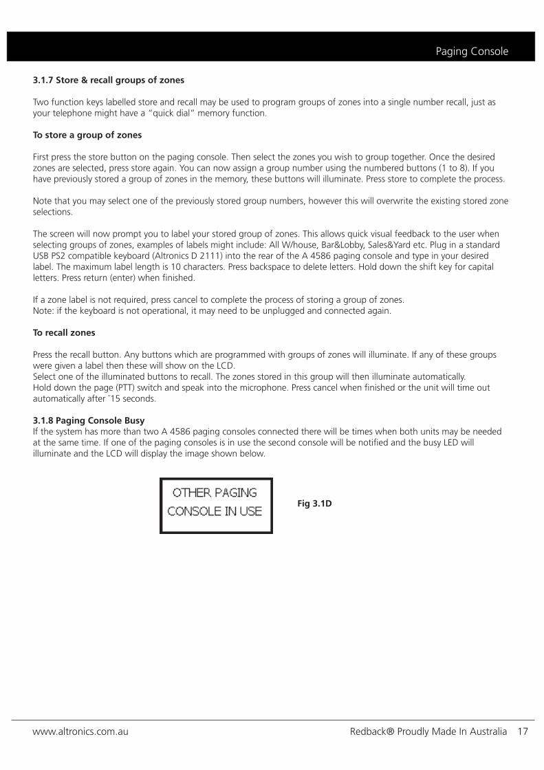
3.1.8 Paging Console Busy If the system has more than two A 4586 paging consoles connected there will be times when both units may be needed at the same time. If one of the paging consoles is in use the second console will be notified and the busy LED will illuminate and the LCD will display the image shown below.
Fig 3.1D

www.altronics.com.auRedback® Proudly Made In Australia18
4.0 TROUBLE SHOOTING
4.1 SYMPTOMS AND REMEDIES
SYMPTOMS REMEDIES
On led doesn’t illuminate Check DC fuse
Keyboard not detected on A 4586
Remove & reinsert keyboard Try another keyboard
Turn A 4585 off and repeat setupMake sure the keyboard is a USB/PS2
keyboard (altronics D 2111)
4.2 RJ45 cabling configuration for system components (586A ‘Straight through’)
System components are connected using “pin to pin” configuration RJ45 data cabling as shown in fig 4.2. When installing ensure all connections are verified with a LAN cable tester before switching any system component on.
Failure to follow the correct wiring configuration may result in damage to system components.
Troubleshooting
586A1 TX+2 TX-3 RX +456 RX-78
Straight Through(both ends)
Pins Face Upwards
1 TX+2 TX-3 RX +456 RX-78
Fig 4.2

www.altronics.com.au Redback® Proudly Made In Australia 19
Specifications
5.0 SPECIFICATIONS
A 4585 Control Unit
Paging console inputs: Data transmission: Front panel controls:Front panel indicators:
Rear panel controls: BGM (background music) input: Evac input:BGM (background music) output: PA (public address) output: A 4575 input:24V DC Switched output:Zone output connectors:Power connection (24V DC): Protection (DC):Dimensions: Weight:
A 4586 Paging Console
Output connection: Data transmission: Front panel controls:
Rear panel controls:Other inputs:
Mic frequency response: Mic Sensitivity:Mic Polar pattern: Power connection (24VDC): Mic gooseneck: Dimensions:
Weight:
4 x RJ45 8P8C Cat5e cabling max 300m
Mic level control,BGM (background music) level con-
trol, zone BGM selection switchesSystem active,Evac active
Evac vox level Dual stereo RCA’s Dual stereo RCA’sDual stereo RCA’sDual stereo RCA’s
RJ45 8P8CEuroblock terminalEuroblock terminalEuroblock terminal
2A M205 482W x 175D x 44H mm
2.5kg
2 x RJ45 8P8C Cat5e cabling max 300m
Zone selection (1-8), store, recall, all call, cancel, PTT switch
Chime output level, mic output levelUSB PS2 compatible keyboard
(type A)100Hz - 10kHz
-76dB ±3dB Cardioid (unidirectional)
2.1mm JACK (centre +ve)325mm
235W x 110D x 55H mm (excluding gooseneck)
0.6kg

www.altronics.com.auRedback® Proudly Made In Australia20
1
ZONE NAMES
2 3 4
5 6 7 8
RECALL 1
1 2 3 4
5 6 7 8
RECALL 2
1 2 3 4
5 6 7 8
RECALL 3
1 2 3 4
5 6 7 8
RECALL 4
1 2 3 4
5 6 7 8
RECALL 5
1 2 3 4
5 6 7 8
RECALL 6
1 2 3 4
5 6 7 8
RECALL 7
1 2 3 4
5 6 7 8
RECALL 8
1 2 3 4
5 6 7 8
RECALL 1
1 2 3 4
5 6 7 8
RECALL 2
1 2 3 4
5 6 7 8
RECALL 3
1 2 3 4
5 6 7 8
RECALL 4
1 2 3 4
5 6 7 8
RECALL 5
1 2 3 4
5 6 7 8
RECALL 6
1 2 3 4
5 6 7 8
RECALL 7
1 2 3 4
5 6 7 8
RECALL 8
1 2 3 4
5 6 7 8
CONSOLE 1
CONSOLE 2
NOTE: All Paging microphones can be programmed with di�erent recalls and labelling.
6.0 A 4586 Programming Sheet
Each A 4586 can store 8 groups of zones using the store & recall function. This permits quick selection of multiple paging zones. Use the set up sheet below to select the groups of zones. Group names have a maximum of 10 characters. A PDF form version of this is available for download on the A 4586 product page at www.altronics.com.au.
Programming Sheets