Embed Size (px)
Citation preview
Operating Manual MICOVERT2000 “New Generation”
Version1.8 I
micovert 2000NewGeneration
FREQUNCY CONVERTER FOR DRIVE SYSTEMS IN LIFT, CRANE AND HIGH-BAY STORAGE TECHNOLOGY
Operating Manual For Functional Description, Installation and Trouble Shooting
Operating Manual MICOVERT 2000 “New Generation”
II Version1.8
KONFORMITÄTSERKLÄRUNG!
Operating Manual MICOVERT2000 “New Generation”
Version1.8 III
1 About this Manual ........................................................................................................ 1
2 Description of the unit .................................................................................................. 4
2.1 Application and definitions 5 2.2 Functions and features 6 2.3 Basic design 8 2.4 Schematic lift run 9
3 Unit design................................................................................................................. 12
3.1 Selecting the proper controller 13 3.2 Power classes and type codes 14 3.3 Operating conditions 15 3.4 Installation 16 3.4.1 General notes and safety precautions 16 3.4.2 Installation in the Control Cabinet 17 3.4.3 Noise suppression 18 3.4.4 Fusing 21 3.5 Safety features 21
4 Interfaces................................................................................................................... 22
4.1 Mains and motor connections 23 4.2 Encoder connection 25 4.3 Interfaces to the control system 27 4.3.1 Inputs in the controller 27 4.3.2 Outputs from the controller 29 4.4 Motor thermistor 31 4.5 Fault memory 31 4.6 Brake resistor 32 4.6.1 Choice of brake resistor 32 4.6.2 Installation instructions 33 4.7 Shaft information 34 4.8 Serial interfaces 35 4.8.1 MICOBUS (optional) 35 4.8.2 Control system setting via PC 35
5 Menus and parameters.............................................................................................. 36
5.1 Preliminaries 37 5.2 Basic menu operation 37 5.2.1 Display, keypad, menus 37 5.2.2 Key functions 38 5.2.3 Switching on the controller 38 5.2.4 Menu structure 39 5.3 Menu descriptions 40 5.3.1 Main menu 40
Operating Manual MICOVERT 2000 “New Generation”
IV Version1.8
5.3.2 SPEED menu 42 5.3.3 SPEED CURVE menu 44 5.3.4 START/STOP menu 47 5.3.4 START/STOP menu 47 5.3.5 DRIVE menu 48 5.3.6 INTERFACES menu 51 5.3.7 OPERATING PARAMETERS menu 53 5.3.8 CONTROLLER PARAMETERS menu 54 5.4 MONITOR menu description 55 5.4.1 MONITOR 1 55 5.4.2 MONITOR 2 55 5.4.3 MONITOR 3 56 5.4.4 MONITOR 4 56 5.5 Fault memory description 57
6 Putting into operation................................................................................................. 58
6.1 Preparations 59 6.1.1 Summary of installation instructions 59 6.1.2 Checking the installation 60 6.2 Entry of main data 61 6.2.1 Switching on the controller 61 6.2.2 Entering the motor parameters 61 6.2.3 Entering inspection speed 62 6.2.4 Inspection run 62 6.3 Normal run start-up 62 6.3.1 Test run 62 6.3.2 Calibration run 63 6.3.3 Setting the stopping accuracy 63 6.3.4 Checking the braking path 63 6.3.5 Checking the stopping accuracy 64 6.3.6 Starting behaviour 64 6.4 Inspection run 64 6.5 Setting V2 and V3 65 6.6 Direct run-in 65
7 Description of Faults .................................................................................................. 66
7.1 Fault diagnosis 67 7.1.1 LED indicators 67 7.1.2 Display messages 67 7.1.3 Unexpected running characteristics 75 7.1.4 Controller faults 76 7.2 Replacement of EPROMS 77 7.3 Servicing and spare parts 77
8 Product liability and warranty..................................................................................... 78

Operating Manual MICOVERT2000 “New Generation”
Version1.8 1
1 About this Manual
For your safety: This Operating Manual uses three types of alert messages to call your attention to im-portant facts:
DANGER: A danger warning describes a procedure or status that may lead to hazard-ous or even fatally dangerous consequences for the user or lift passenger.
CAUTION: This type of message indicates operations which may damage the control-ler, the control system or the drive. However, any such damage may lead to injury or death (e.g. in case of fire).
PLEASE NOTE: This type of message contains information about specific work steps. It explains facts, defines terms or provides tips on how to simplify a procedures or an operating sequence.
Please observe the following safety notes! Although the MICOVERT controller has been developed for your protection in compli-ance with all safety measures, it is not possible to exclude faults. In the interest of your own safety and that of your colleagues please note the following instructions:
DANGER: Sharp edges and sensitive components! When carrying equipment without packaging, hold the side elements. Gripping under circuit boards or metal panels can cause damage to the equipment and injury to yourself.
DANGER: Risk of crushing and damage to the controller if it does not have a firm stand. Be sure to place the controller on a flat surface which can support its weight be-fore installation! Do not stand the controller on end as it could fall over.
DANGER: When mains power is applied, the inside of the controller and its external terminals will be under high voltage. Touching live components can be fatal! Before switching on the power supply, make sure that the front panel of the controller is screwed in properly! Never poke inside the controller through the bottom or top with long objects (pliers, screwdrivers ...) during operation (power on)!
Operating Manual MICOVERT 2000 “New Generation”
2 Version1.8
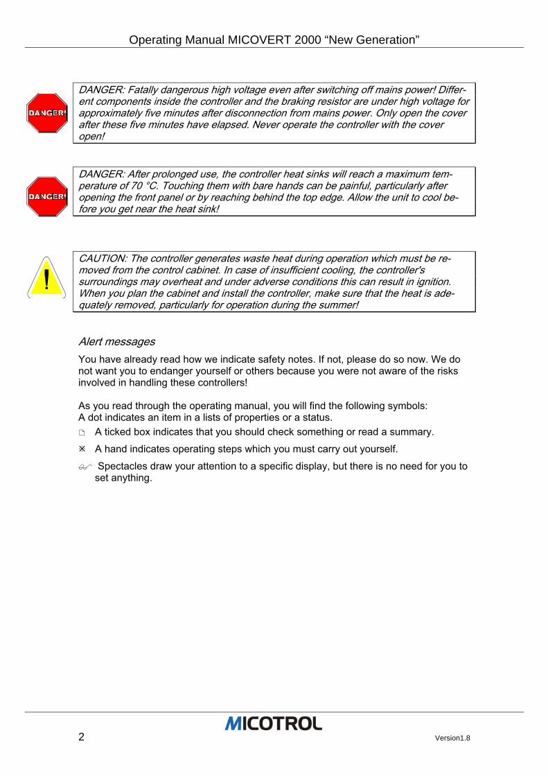
DANGER: Fatally dangerous high voltage even after switching off mains power! Differ-ent components inside the controller and the braking resistor are under high voltage for approximately five minutes after disconnection from mains power. Only open the cover after these five minutes have elapsed. Never operate the controller with the cover open!
DANGER: After prolonged use, the controller heat sinks will reach a maximum tem-perature of 70 °C. Touching them with bare hands can be painful, particularly after opening the front panel or by reaching behind the top edge. Allow the unit to cool be-fore you get near the heat sink!
CAUTION: The controller generates waste heat during operation which must be re-moved from the control cabinet. In case of insufficient cooling, the controller's surroundings may overheat and under adverse conditions this can result in ignition. When you plan the cabinet and install the controller, make sure that the heat is ade-quately removed, particularly for operation during the summer!
Alert messages You have already read how we indicate safety notes. If not, please do so now. We do not want you to endanger yourself or others because you were not aware of the risks involved in handling these controllers! As you read through the operating manual, you will find the following symbols: A dot indicates an item in a lists of properties or a status.
A ticked box indicates that you should check something or read a summary.
A hand indicates operating steps which you must carry out yourself.
Spectacles draw your attention to a specific display, but there is no need for you to set anything.
Operating Manual MICOVERT2000 “New Generation”
Version1.8 3
MICOVERT Controllers © 2003 MICOTROL International GmbH COPYRIGHT The MICOVERT 2000 series controllers and this operating manual are protected by copyright. Imitation of these units will be prosecuted. All rights to the operating manual, including the rights of reproduction in any conceivable form, be it by photocopying, printing or recording on data carriers, and including translations, are reserved. This op-erating manual or parts thereof may not be reprinted without the express written permission of MICOTROL. This operating manual describes the product as exactly as possible but gives no guar-antee for any specific characteristics or its success in use. The operating manual was checked carefully prior to publication. The authors give a warranty that the operating manual contains no errors which make it useless or detracts from their usefulness for the unit's implied use. However, the publisher does not accept any liability, neither ex-pressly nor implicitly, for damage or consequential damage resulting from the use of the operating manual. We shall be grateful for all corrections, suggestions and criti-cism! The state of technology at the time of the joint dispatch of product and operating man-ual by MICOTROL shall be decisive, unless otherwise stated. Technical modifications are subject to change without prior notice; previous operating manuals become invalid. The General Terms of Business of MICOTROL shall apply. MICOTROL International GmbH Daimlerstraße 6 D-63755 Alzenau Tel. +49 (0) 60 23 - 50 56 80 Fax +49 (0) 60 23 – 50 56 99 Alzenau, 01.01.2004
Operating Manual MICOVERT 2000 “New Generation”
4 Version1.8
2 Description of the unit
2.1 Application and definition
2.2 Functions and features
2.3 Basic design
2.4 Schematic lift run
Chapter overview: This chapter introduces you to the basics of the MICOVERT 2000 controllers and to their use in comfort lifts. Read this chapter if you want to learn more about the technol-ogy of MICOTROL lift controllers and their integration in the control system.
Operating Manual MICOVERT2000 “New Generation”
Version1.8 5
2.1 Application and definitions
Area of application The MICOVERT 2000 series of controllers consists of phase control frequency con-verters for lift drives with exceptionally high running comfort. The controllers are designed to control variable speed asynchronous lift motors in conjunction with a breaking resistor, digital encoder (pulse generator) and a higher-level control system. The MICOVERT 2000 controller product line and accessories are designed for electri-cal speed regulation, drive and positioning of three phase asynchronous motors. Areas of application are:
• Passenger lifts
• Material and load lifts
• Drives in crane facilities
• Drives in high-bay stores These are the only applications; the controller is not designed for other reasons. Espe-cially not for high dynamic drives, with precision positioning systems except the shown ones.
Definitions Conveying systems: Passenger lifts, material and load lifts, crane facilities, high-bay stores. The controllers can be used on lifting and travelling gear. Three-phase asynchronous motors: The controllers are suited for two motor types:
• variable squirrel-cage motors with a torque characteristic for electronic speed con-trollers with voltage dosing (like MICOMPACT 330) or
• similar standard motors of all types designed and built for speed control through frequency converters.
Radio interference suppression: Without a radio interference filter at the power input, and if the installation instructions in Chapter 3.4.3 are not observed, neither level EN55011/55022 Class B will be at-tained!
PLEASE NOTE: The operator of the overall system is responsible for observing the postal regulations in force at his location as well as for the interpretation and obser-vance of accident prevention regulations and compliance with all pertinent standards and statutes.
Operating Manual MICOVERT 2000 “New Generation”
6 Version1.8
2.2 Functions and features
Connection to higher-level Controller The MICOVERT 2000 series controller can receive commands from special higher-level controllers and send back status information over a serial link. The parameter ad-justments can be made with a LC-Display and keypad; alternatively a PC and the MICOTROL-Software (Micoview) could be used.
Additional Connectors (for details see Chapter 4, Interfaces) For best operation issues an appropriate incremental encoder has to be connected. The main supply has to be made with three-phase voltage. A motor temperature sen-sor has to be connected to the Inverter.
The main features and functions:
• The MICOVERT 2000 series: Efficient vector-regulated transistor pulse-controlled AC converter with high running comfort and best stopping precision. For supplying power to single speed standard asynchronous machines or polarity-reversing lift motors.
• Range of nominal current: 10 A to 100 A
• Mains connection: 50 or 60 Hz, available for various mains voltages.
• Power pack: IGBT module for cycle frequencies up to 16 kHz, very low noise lev-els. Earth fault and short-circuit proof.
• Radio-suppression: Integrated radio-interference filter (10 to 50A units).
• Control section: Fully digitised, thus high and lasting control accuracy.
• Controller set-up: Via menu structure with four-key navigation; all status signals via LCD (liquid crystal display).
• PC control system (optional): All controller settings can also be entered via an IBM-compatible PC instead of using the four-key pad and LCD; the PC is connected to the controller via a standard RS-232 interface. Password-based locking as well as online display of the running curve (set-point and actual value curve).
• MICOBUS control system (optional): LS2/LS3, DCP3, DCP4
• Automatic determination of braking path.
• Six different operating speeds.
• Six output relays with floating contacts; the user can allocate one contact with dif-ferent functions.
• Monitoring and safety functions: Motor temperature monitoring, encoder monitoring, heat sink temperature monitoring, short-circuiting and earth-circuiting monitoring.
Operating Manual MICOVERT2000 “New Generation”
Version1.8 7
• Direct running-in subject to appropriately accurate well information.
• Four quadrant operation: No direction contactors necessary.
Operating Manual MICOVERT 2000 “New Generation”
8 Version1.8
2.3 Basic design
The MICOVERT 2000 series, power circuit The speed of the three-phase motor is varied by the indirect voltage converter and con-trolled through the evaluation of an actual speed signal (encoder signal). The motor may be either a regulated special motor generally used in lift technology or a standard variable speed motor. The main supply for the power circuit (IGBT modules) is a three-phase supply through the radio-suppression filter and a non-controlled mains rectifier in the intermediate circuit. Only the active power is taken from the mains net-work. The mains power supply for the electronics and the recharging of the intermediate circuit is done through a three-phase supply on the controller board. The required torque for the motor is gained through pulse width modulation from the constant intermediate voltage. The sinusoidal current and the frequency are varied ac-cording to the required torque. Frequency and voltage are reduced for the braking operation and the motor feeds generator energy back to the intermediate circuit and the brake resistor.
Control section The control design is based on an ideal lift run curve, taking passenger sensations into account. Ramp-up is time dependent; ramp-down is travel dependent. Halting is con-trolled down to drive speed ZERO. Thus the mechanical brake only has a retention and safety function and is not subjected to wear. Driving and braking are controlled by a specified speed program derived from the ideal run curve for passengers' sensation of acceleration. The complete control layout in digital technology with two micro-controllers enables maximum support from the controller's operating software during commissioning. The controller calculates the essential lift and operating parameters itself and saves them permanently in an internal memory.
Operating Manual MICOVERT2000 “New Generation”
Version1.8 9
2.4 Schematic lift run
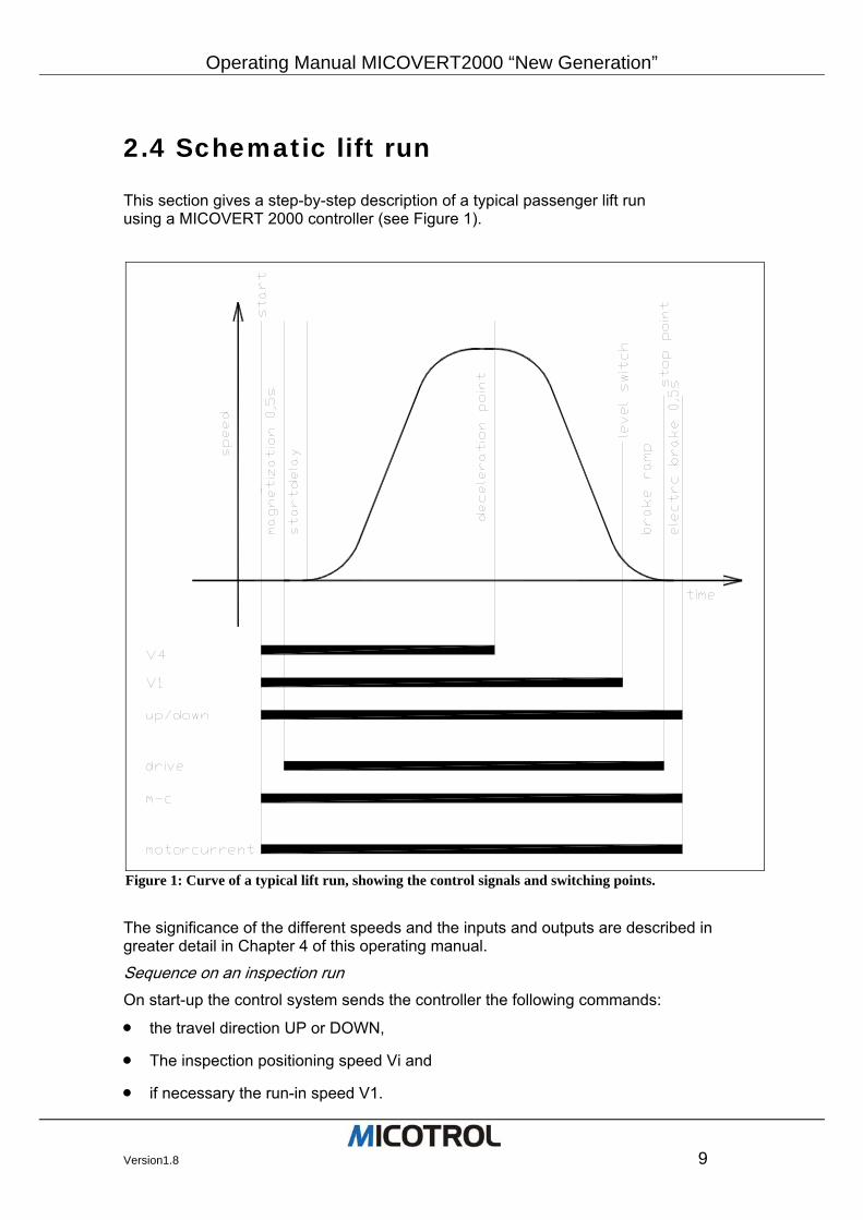
This section gives a step-by-step description of a typical passenger lift run using a MICOVERT 2000 controller (see Figure 1).
The significance of the different speeds and the inputs and outputs are described in greater detail in Chapter 4 of this operating manual.
Sequence on an inspection run On start-up the control system sends the controller the following commands:
• the travel direction UP or DOWN,
• The inspection positioning speed Vi and
• if necessary the run-in speed V1.
Figure 1: Curve of a typical lift run, showing the control signals and switching points.
Operating Manual MICOVERT 2000 “New Generation”
10 Version1.8
The controller provides the following signals to the control system via floating relay contacts:
• switch on main contactor (CONTACTOR relay) and
• clear mechanical brake (DRIVE relay). The controller controls the motor torque dependent on the load. The drive accelerates to the set-point value of the stipulated inspection or normal run-in speed. When the inspection speed is stopped, the main contactor and the mechanical brake are switched off by the control system (brake is applied).
PLEASE NOTE: The UP or DOWN command must be switched off at the same time as the main contactor is switched off. Only then is the controller output blocked. Otherwise the controller sends an error message: ERROR-11: ”int. under voltage” or ERROR-13: ”contactor travel”!
Sequence on a normal run
Start On start-up the control system sends the controller the following commands:
• run direction UP or DOWN,
• desired end speed V2, V3 or V4, or
• run-in speed V1. The controller provides the following signals to the control system through the relay contacts:
• switch on main contactor (CONTACTOR relay) and
• release mechanical brake (DRIVE relay) with 0.5 second delay. The controller regulates the torque of the motor dependent on load. The drive accelerates to the set-point value of the stipulated constant speed.
Acceleration Normally the cabin is set in motion quickly and without jolting. Acceleration is increased according to the run's program and is reduced prior to transition into end speed. The transition form can be set through the jolt-acceleration (round-off factor).
Deceleration The control system switches off the fast run command V2, V3 or V4 at the deceleration point. From the calibration run conducted during first-time operation, the travel calcula-tor in the controller knows the distance left to the levelling switch. Using this data, it continuously calculates the last moment at which the deceleration phase must be initi-ated to arrive reliably at level stop position. It is not until this moment is reached, that the lift slows down to run-in speed V1 as determined by the distance calculator. Upon reaching the levelling flag (about 4 to 10 cm before the stop) the control system cuts out the run-in speed V1 and the drive decelerates down to the ZERO speed, stops the motor electrically and allows the run relay to drop out at which point the brake is ap-plied. The contactor relay breaks with a delay of 0.5 s. During this time the motor is still held electrically until the mechanical brake has been safely applied . For the electric stop function, the motor also needs current. Therefore the main contac-tor and the direction signal UP or DOWN must remain switched on after the level signal has been given. If the main contactor is switched off when the standstill signal is given,
Operating Manual MICOVERT2000 “New Generation”
Version1.8 11
the drive could start up again after stopping until the mechanical brake has been ap-plied. The controller controls the delay time up to the moment when the main contactor drops out; the main contactor is connected directly to the CONTACTOR output relay.
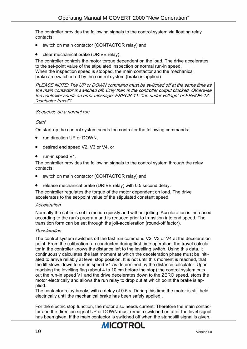
Sequence on a POINTED-CURVE run A pointed-curve run is a travel curve in which the specified end speed is not yet reached at the deceleration point (by well switch). In this case, while the run is still in-creasing in speed, the controller calculates the point in time (point on the path) at which the braking phase must actually be introduced in order to reach the destination floor at run-in speed (see Figure 2).
Applications are floor-to-floor runs at high end speed and offset floors. The shortest possible run time is then achieved because the lift continues to accelerate after passing the well switch.
Figure 2: Travel sequence on a pointed-curve run (see text).
Operating Manual MICOVERT 2000 “New Generation”
12 Version1.8
3 Unit design
3.1 Selecting the proper controller
3.2 Power classes and type codes
3.3 Operating conditions
3.4 Installation notes 3.4.1 General notes and safety precautions 3.4.2 Installation in the Control Cabinet 3.4.3 Noise suppression 3.4.4 Fusing
3.5 Safety features
Chapter overview: This chapter contains important information on the controller product line, on the selec-tion of the best suited MICOVERT controller, on installation preliminaries and on the operating conditions.
Operating Manual MICOVERT2000 “New Generation”
Version1.8 13
3.1 Selecting the proper controller
Depending on your application and requirements, determine the following main vari-ables for your order:
Mains voltage.
Nominal motor current.
Nominal controller current: Must be equal to or greater than the nominal motor cur-rent.
Older motors where the flywheel mass can’t reduced take the next higher controller with more power.
Control voltage: Depends on the lift control system and must be agreed upon with the control system manufacturer.
Digital encoder: Key data: 1,024 to 4,096 pulses/revolution, push-pull HTL (high-threshold logic) level, operating voltage 10 to 30VDC, max. load 100mA.
Digital encoder: TTL (transistor-transistor logic) level, 4 channels, operating volt-age 5VDC, max. 180mA.
Brake resistor: See Chapter 4.6.
ATTENTION: To use ready-made encoder wiring with Sub-D connectors please specify the encoder type in your order.
Operating Manual MICOVERT 2000 “New Generation”
14 Version1.8
3.2 Power classes and type codes
• The controllers are available in the sizes given below (see Figure 3 and 4). Higher power classes on request.
• Mains voltages of 400V three-phase current or as required, mains frequency 50/60Hz.
• Control voltages as required, AC or DC.
• Power classes
Nominal Motor current (A)
Current limiting max. 10 s (A)
Main fuse NH
Powerdissipation (W)
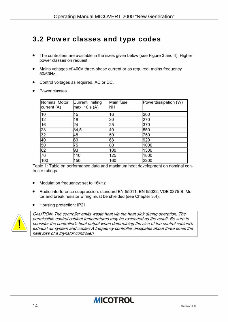
10 15 16 200 12 18 20 270 16 24 25 370 23 34,5 40 550 32 48 50 750 40 60 63 920 50 75 80 1000 62 93 100 1300 76 110 125 1800 100 150 160 2200
Table 1: Table on performance data and maximum heat development on nominal con-troller ratings
• Modulation frequency: set to 16kHz
• Radio interference suppression: standard EN 55011, EN 55022, VDE 0875 B. Mo-tor and break resistor wiring must be shielded (see Chapter 3.4).
• Housing protection: IP21
CAUTION: The controller emits waste heat via the heat sink during operation. The permissible control cabinet temperatures may be exceeded as the result. Be sure to consider the controller's heat output when determining the size of the control cabinet's exhaust air system and cooler! A frequency controller dissipates about three times the heat loss of a thyristor controller!
Operating Manual MICOVERT2000 “New Generation”
Version1.8 15
3.3 Operating conditions
The controller complies with the relevant DIN and VDE standards and applicable to units of this type. This chapter describes units designed for operation in lifts and other conveying sys-tems. Electric power and constant load
• The start-up current may reach the set limit level for a maximum period of 10 sec-onds.
• The mains power supply tolerance is +10/-15%.
• A maximum 240 runs per hour are permitted for lift and automated warehousing applications at an ambient temperature of less than 45°C. The controller switches off automatically should a limit temperature be exceeded by the motor and/or con-troller.
• PLEASE NOTE: Start-up current: Normally the controller limits the maximum start-up current to 2 times the nominal current of the motor (standard). However it must be determined whether this is sufficient for the specific application. It may be nec-essary to consult the motor manufacturer. If a higher start-up current should be necessary, a frequency converter with a higher rating may be need to be selected.
Operating temperature The units are designed in accordance with DIN/VDE 0558 for an ambient temperature (in this case: control cabinet temperature) of 45°C. If higher temperatures are specified, it may be possible to use a controller in a higher nominal power class from case to case. This alternative must always be clarified in advance with MICOTROL!
Operating Manual MICOVERT 2000 “New Generation”
16 Version1.8
3.4 Installation
3.4.1 General notes and safety precautions
DANGER: During controller operation, certain parts of the unit are inherently under dangerous high voltage. Appropriate precautions must be taken when installing the unit in the control cabinet, especially separate covers for live parts. IMPORTANT: Even af-ter the controller system has been switched off, some components within the system and the brake resistor remain under high voltage for about five minutes.
Be sure to mount the lower metal cover before switching on the mains supply. All adjustment procedures can be carried out with the unit closed!
Be sure to observe the pertinent regulations and guidelines of your power sup-ply company. Also be sure to follow the relevant installation guidelines for the site by the plant operator as well as the applicable accident prevention regulations.
Only qualified technicians (electricians or persons with electrical engineering train-ing) are allowed to carry out the installation work.
Shock protection precautions must be taken before carrying out adjusting and ser-vicing tasks while the mains supply is switched on (VDE 0680).
The unit meets VBG4 requirements in ready-to-use condition.
Be sure to observe the pertinent VDE and DIN standards, especially VDE 0105 and DIN EN 60204-1 and DIN 57105, during installation and when working on the plant.
Electrical connections for the motor, control system and controller must be made in accordance with the appropriate terminal diagrams and with due consideration to the pertinent VDE regulations and the guidelines of your local electric power supply company.
Operating Manual MICOVERT2000 “New Generation”
Version1.8 17
3.4.2 Installation in the Control Cabinet
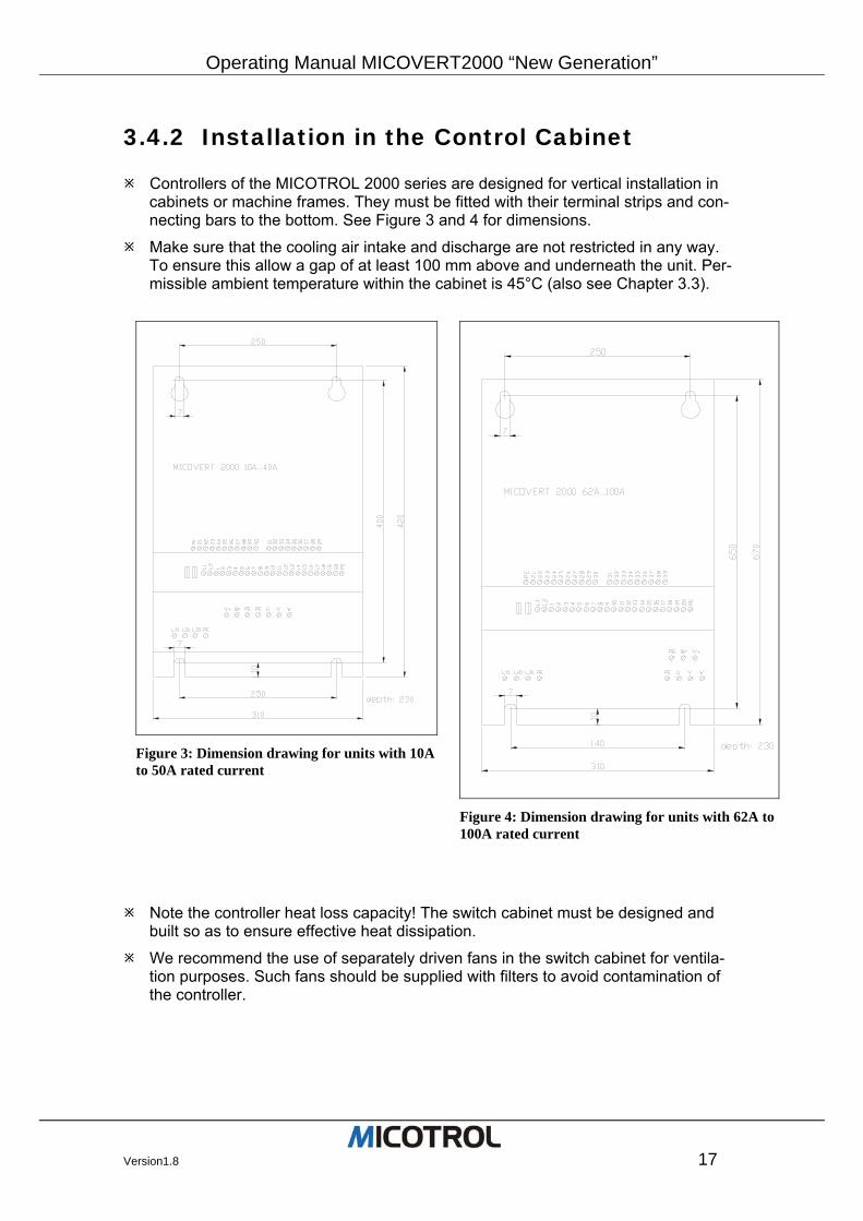
Controllers of the MICOTROL 2000 series are designed for vertical installation in cabinets or machine frames. They must be fitted with their terminal strips and con-necting bars to the bottom. See Figure 3 and 4 for dimensions.
Make sure that the cooling air intake and discharge are not restricted in any way. To ensure this allow a gap of at least 100 mm above and underneath the unit. Per-missible ambient temperature within the cabinet is 45°C (also see Chapter 3.3).
Note the controller heat loss capacity! The switch cabinet must be designed and built so as to ensure effective heat dissipation.
We recommend the use of separately driven fans in the switch cabinet for ventila-tion purposes. Such fans should be supplied with filters to avoid contamination of the controller.
Figure 3: Dimension drawing for units with 10A to 50A rated current
Figure 4: Dimension drawing for units with 62A to 100A rated current
Operating Manual MICOVERT 2000 “New Generation”
18 Version1.8
3.4.3 Noise suppression This section describes the necessary measures for radio-interference suppression as required by law and EMC (electromagnetic compatibility) regulations.
Radio suppression Radio suppression level EN55011/55022 Class B is attained. This corresponds to an interference emission level admissible, for example, in residential areas, hospitals and office environments. A prerequisite for level N, however, is the integration of a radio-interference filter at the power input (10 to 50A internally, 62 to 100A externally) and the compliance with all installation instructions.
PLEASE NOTE: Radio suppression level EN55011/55022 Cass B can only be achieved when all installation requirements for the controller, its connections and all associated electrical components are observed!
Noise filter Without a radio interference suppression filter at the input, the required level of radio shielding according to EN 55011 Class B cannot be attained. Units of the 10 to 40A rated current series are equipped with an integrated radio interference suppression fil-ter (standard); whereas for units of the 62 to 100A rated current series, the radio interference suppression filter must be implemented externally.
PLEASE NOTE: This is true for all such converters available on the market!
Residual-current (FI-type) circuit-breakers can be tripped inadvertently when power is switched on if a noise filter is being used. Only use residual-current circuit-breakers with a drop-out delay.
Due to the high leakage current caused by the noise filter, the PE connection cable must have a cross section of at least 10 mm2.
General installation notes
The following controller installation instructions must be strictly observed; otherwise EMC (electromagnetic compatibility) cannot be guaranteed:
The cable between the frequency converter and the motor/brake resistance must be shielded. Only use copper shielding; steel shielding is not suited here!
The shielding of the motor supply cable and brake resistance cable must be applied on both sides over a large area from the cable clip on motor housing to the cable clip on the controller.
Shielded leads must be used for encoders. The encoder shielding must be applied to both sides: on the motor side directly to the housing (PE), on the controller side to terminal 31 (capacitor for PE).
Relays and contactors integrated in the same circuit must be equipped with spark-quenching combinations and over voltage protection components respectively. Suitable R-C combinations must be used for radio interference suppression of all contactors. This also applies to components which are not in the cabinet!
Control and encoder leads must be laid separately to the load lines.
Cable in the cabinet must be routed as close as possible to the reference potential. Dangling cables are prime EMC suspects due to their active and passive antenna effect.
Operating Manual MICOVERT2000 “New Generation”
Version1.8 19
All metallic components in the cabinet must be connected with large contact areas and good HF conductivity. Beware of anodised oxide layers or yellow chromated coatings (on rails, screws, bolts etc.) which may have very high resistance values in certain frequency ranges! It is best to use an aluminium mounting plate in the cabi-net.
The system designer must consider HF noise generation as well as noise suscepti-bility among the converters and plan appropriate preventive measures.
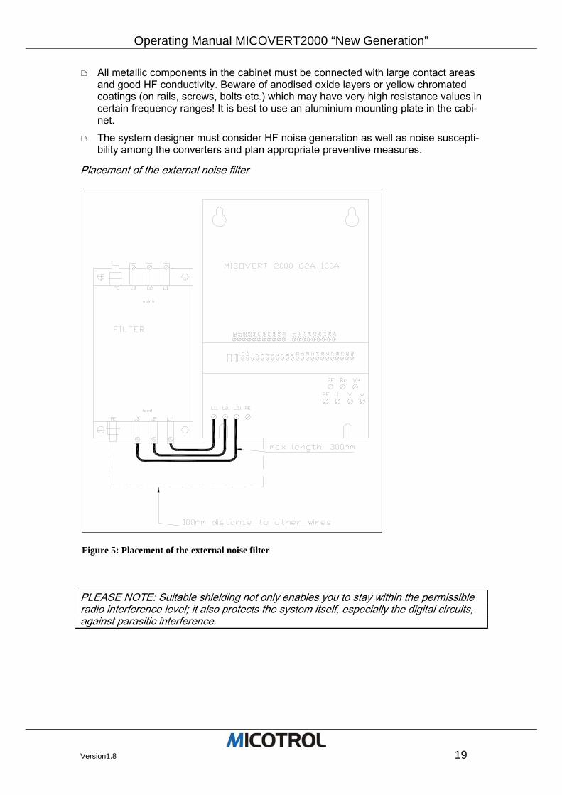
Placement of the external noise filter
PLEASE NOTE: Suitable shielding not only enables you to stay within the permissible radio interference level; it also protects the system itself, especially the digital circuits, against parasitic interference.
Figure 5: Placement of the external noise filter
Operating Manual MICOVERT 2000 “New Generation”
20 Version1.8
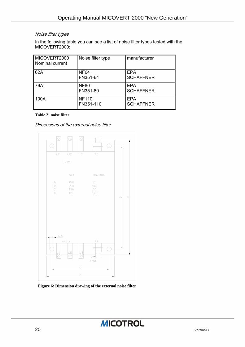
Noise filter types In the following table you can see a list of noise filter types tested with the MICOVERT2000: MICOVERT2000 Nominal current
Noise filter type manufacturer
62A NF64 FN351-64
EPA SCHAFFNER
76A NF80 FN351-80
EPA SCHAFFNER
100A NF110 FN351-110
EPA SCHAFFNER
Table 2: noise filter
Dimensions of the external noise filter
Figure 6: Dimension drawing of the external noise filter
Operating Manual MICOVERT2000 “New Generation”
Version1.8 21
3.4.4 Fusing Low voltage HRC fuses are suitable for short-circuit protection for the power modules (see Figure-7)
3.5 Safety features
The controller design ensures that excitation of the MAINS, CONTACTOR and RUN relays is interrupted immediately in the event of a controller fault, even if the lift has not stopped, ensuring that the mechanical brake can be applied.
• If any faults occur in the control system or if the direction signal is lost, the output stages are switched off circuit immediately and the mechanical brake is deactivated through loss of the RUN signal. Independently of this, the system ensures that the power supply to the power circuit is switched off no later than 0.5 s after the RUN relay drops out, causing the motor windings to be reenergized. If the encoder fails, or the deviation between set value and actual value for speed exceeds 10%, the controller will bring the cabin to a halt.
• If the heat sink temperature is too high, the circuit breaker will switch off the control-ler when the next stop position is reached.
• If the admissible motor temperature is exceeded (PTC thermistor evaluation), the drive will be brought to an immediate standstill.
PLEASE NOTE: The controller is not a safety device as defined by lift regulations. The monitoring functions of the controller described above do not release the lift builder from his responsibility to observe the statutory safety regulations. The lift control sys-tem is the first level integrated in the safety chain.
Disposal MICOTROL will take back old units free of charge provided they are delivered car-riage paid to the MICOTROL factory in Alzenau, Germany. Applicable local waste treatment and disposal regulations must be observed if you dis-pose of a unit yourself or replace any components. MICOTROL shall accept no liability for any parts and components that are not disposed of properly! The following details are useful for disposal purposes:
• The controller's heat sink and side sections are made of aluminium, usually without lacquering or surface treatment.
• The front panel is made of printed aluminium sheet.
• Regulations on the disposal of electronic parts and components apply for the dis-posal of the main p.c. board, the LCD unit and the ignition protective circuit board.
• The power semiconductors contain no beryllium and can thus be disposed as elec-tronics crap.
Operating Manual MICOVERT 2000 “New Generation”
22 Version1.8
4 Interfaces
4.1 Mains and motor connections
4.2 Encoder connection
4.3 Interfaces to the control system 4.3.1 Inputs in the controller 4.3.2 Outputs from the controller
4.4 Motor PTC thermistor
4.5 Fault memory
4.6 Brake resistor 4.6.1 Choice of brake resistor 4.6.2 Installation instructions
4.7 Shaft information
4.8 Serial interface 4.8.1 MICOBUS (optional) 4.8.2 Control system setting via PC Chapter summary This chapter contains all the details on the controller's connections. The information is important for installation and commissioning (see Chapters 5 and 6).
Operating Manual MICOVERT2000 “New Generation”
Version1.8 23
4.1 Mains and motor connections
Suitable drive motors The controllers can be driven with two types of motor:
• Single-speed standard motor or similar standard motor without separate ventilation.
• Variable three-phase asynchronous motors used as special motors in non-controlled lifts or with thyristor controllers.
CAUTION: Increased voltage peaks occur at the motor when using long motor connec-tion cables (more than 15 m in length), which can reduce the service life of the windings. Only use motors for rate-of-rise-of-current values greater than 2 kV/µs or connect output throttles on the controller.
Centrifugal masses: Since the controller not only controls the entire drive train, but must also compensate short-term set-point fluctuations, it is best to dispense with addi-tional centrifugal masses. The reduction of centrifugal masses results in a considerable saving in energy while significantly decreasing thermal loading for the motor. This also applies to the conversion of old systems in which the existing centrifugal mass should be replaced by a lightweight aluminium or plastic hand wheel (as far as this is permit-ted by statutory regulations). It is important that the motor is of low-noise design.
Mains and motor connections Available mains voltages: 230VAC +10% / -15% 400VAC +10% / -15% 415VAC +10% / -15% Other mains voltages upon request. Please state required mains voltage when ordering.
• To ensure that the safety circuit is closed before the start of a run, the mains input to the controller board is connected in front of the main contactor. The mains input to the power section is connected behind the main contactor.
CAUTION: The converter will be destroyed, if the main contactor is not connected properly! Make absolutely sure that the inverter board (terminals L1, L2) is supplied with power before the main contactor is activated!
• Check the motor rating plate for star delta connection.
• Apply the cable shielding on the motor housing over a wide surface area (wrap-around contacting)..
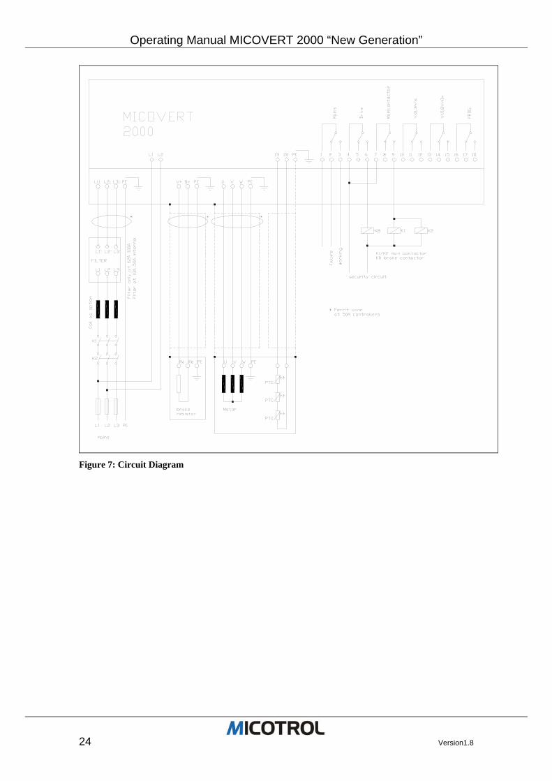
For connection details, see circuit diagram Figure 7:
Operating Manual MICOVERT 2000 “New Generation”
24 Version1.8
Figure 7: Circuit Diagram
Operating Manual MICOVERT2000 “New Generation”
Version1.8 25
4.2 Encoder connection
A motor encoder is required to scan the actual speed and calculate the distance of the run. The standard 2000 series controller is suited for use with digital encoders (incre-mental encoders).
PLEASE NOTE: The higher the pulse rate from the digital speed scan, the better the control characteristic at low speed, especially in the start-up phase.
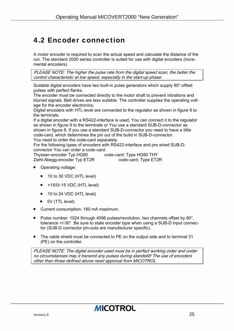
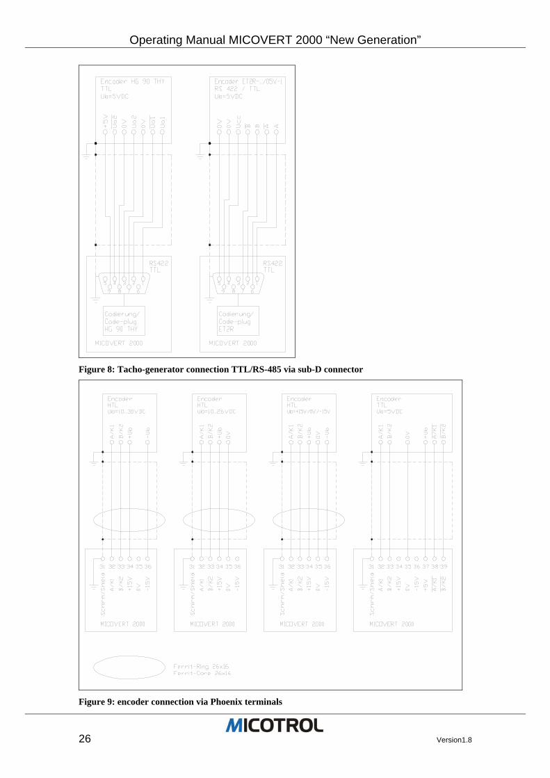
Suitable digital encoders have two built-in pulse generators which supply 90°-offset pulses with perfect flanks. The encoder must be connected directly to the motor shaft to prevent vibrations and blurred signals. Belt drives are less suitable. The controller supplies the operating volt-age for the encoder electronics. Digital encoders with HTL-level are connected to the regulator as shown in figure 9 to the terminals. If a digital encoder with a RS422-interface is used, You can connect it to the regulator as shown in figure 9 to the terminals or You use a standard SUB-D-connector as shown in figure 8. If you use a standard SUB-D-connector you need to have a little code-card, which determines the pin out of the build in SUB-D-connector. You need to order the code-card separately. For the following types of encoders with RS422-interface and pre wired SUB-D-connector You can order a code-card: Thyssen-encoder Typ HG90 code-card: Type HG90 THY Ziehl-Abegg-encoder Typ ET2R code-card: Type ET2R
• Operating voltage:
• 10 to 30 VDC (HTL level)
• +15/0/-15 VDC (HTL level)
• 10 to 24 VDC (HTL level)
• 5V (TTL level)
• Current consumption: 180 mA maximum.
• Pulse number: 1024 through 4096 pulses/revolution, two channels offset by 90°, tolerance +/-30°. Be sure to state encoder type when using a SUB-D input connec-tor (SUB-D connector pin-outs are manufacturer specific).
• The cable shield must be connected to PE on the output side and to terminal 31 (PE) on the controller.
PLEASE NOTE: The digital encoder used must be in perfect working order and under no circumstances may it transmit any pulses during standstill! The use of encoders other than those defined above need approval from MICOTROL.
Operating Manual MICOVERT 2000 “New Generation”
26 Version1.8
Figure 8: Tacho-generator connection TTL/RS-485 via sub-D connector
Figure 9: encoder connection via Phoenix terminals
Operating Manual MICOVERT2000 “New Generation”
Version1.8 27
4.3 Interfaces to the control system
4.3.1 Inputs in the controller
Control voltage The control voltage of 20VDC is available on terminal 21 (only use for command signal input!). Input curent approx. 10 mA. Other control voltages (12 to 250V) are to be ex-pressly stated when ordering. All control voltage inputs are potentially isolated via optocouplers. The external DC control voltage must be smoothed (tolerance +/-20%).
If command wiring exceeds 1,5m use shielded cable. Connect shield to PE termi-nal.
PLEASE NOTE: You must specify the command voltage when ordering the controller.
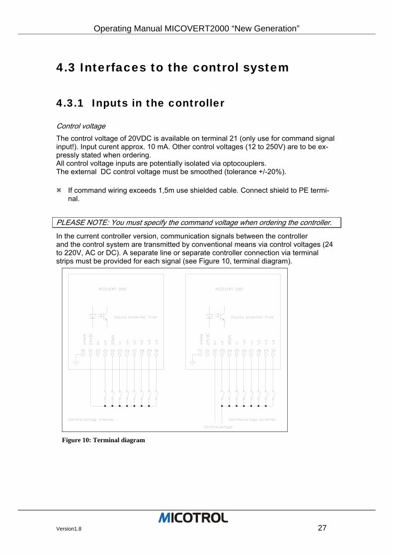
In the current controller version, communication signals between the controller and the control system are transmitted by conventional means via control voltages (24 to 220V, AC or DC). A separate line or separate controller connection via terminal strips must be provided for each signal (see Figure 10, terminal diagram).
Figure 10: Terminal diagram
Operating Manual MICOVERT 2000 “New Generation”
28 Version1.8
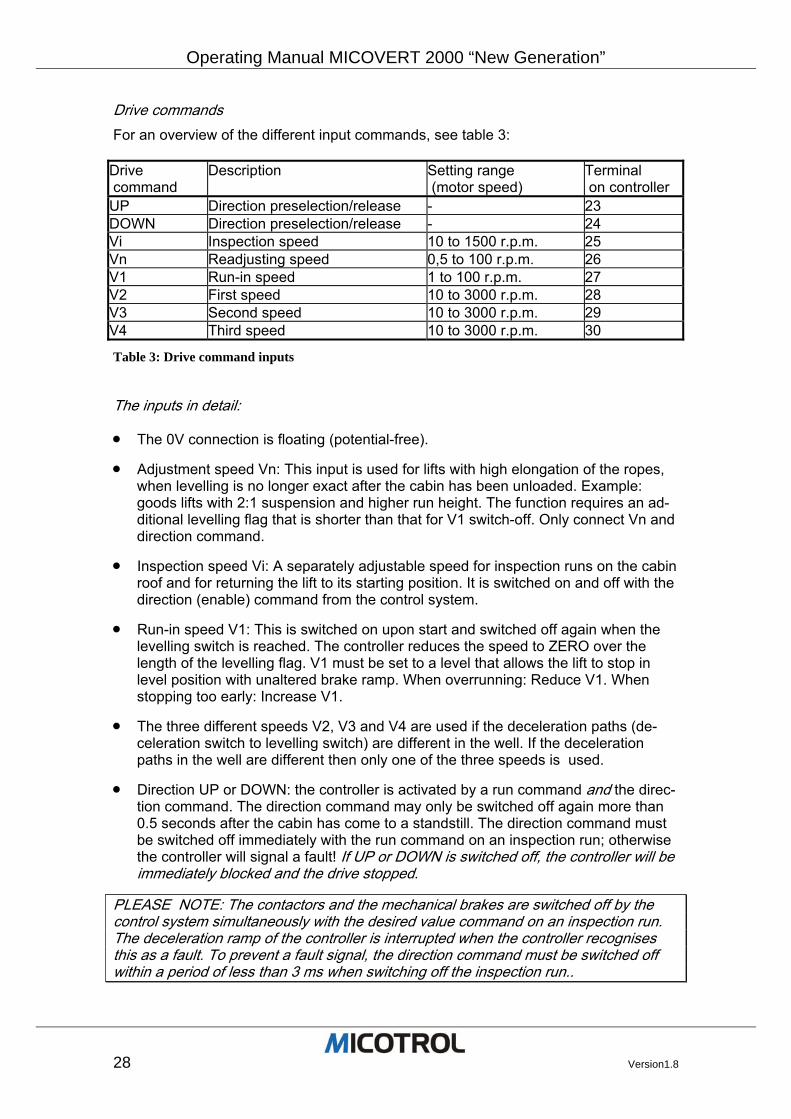
Drive commands For an overview of the different input commands, see table 3: Drive command
Description Setting range (motor speed)
Terminal on controller
UP Direction preselection/release - 23 DOWN Direction preselection/release - 24 Vi Inspection speed 10 to 1500 r.p.m. 25 Vn Readjusting speed 0,5 to 100 r.p.m. 26 V1 Run-in speed 1 to 100 r.p.m. 27 V2 First speed 10 to 3000 r.p.m. 28 V3 Second speed 10 to 3000 r.p.m. 29 V4 Third speed 10 to 3000 r.p.m. 30
Table 3: Drive command inputs
The inputs in detail:
• The 0V connection is floating (potential-free).
• Adjustment speed Vn: This input is used for lifts with high elongation of the ropes, when levelling is no longer exact after the cabin has been unloaded. Example: goods lifts with 2:1 suspension and higher run height. The function requires an ad-ditional levelling flag that is shorter than that for V1 switch-off. Only connect Vn and direction command.
• Inspection speed Vi: A separately adjustable speed for inspection runs on the cabin roof and for returning the lift to its starting position. It is switched on and off with the direction (enable) command from the control system.
• Run-in speed V1: This is switched on upon start and switched off again when the levelling switch is reached. The controller reduces the speed to ZERO over the length of the levelling flag. V1 must be set to a level that allows the lift to stop in level position with unaltered brake ramp. When overrunning: Reduce V1. When stopping too early: Increase V1.
• The three different speeds V2, V3 and V4 are used if the deceleration paths (de-celeration switch to levelling switch) are different in the well. If the deceleration paths in the well are different then only one of the three speeds is used.
• Direction UP or DOWN: the controller is activated by a run command and the direc-tion command. The direction command may only be switched off again more than 0.5 seconds after the cabin has come to a standstill. The direction command must be switched off immediately with the run command on an inspection run; otherwise the controller will signal a fault! If UP or DOWN is switched off, the controller will be immediately blocked and the drive stopped.
PLEASE NOTE: The contactors and the mechanical brakes are switched off by the control system simultaneously with the desired value command on an inspection run. The deceleration ramp of the controller is interrupted when the controller recognises this as a fault. To prevent a fault signal, the direction command must be switched off within a period of less than 3 ms when switching off the inspection run..
Operating Manual MICOVERT2000 “New Generation”
Version1.8 29
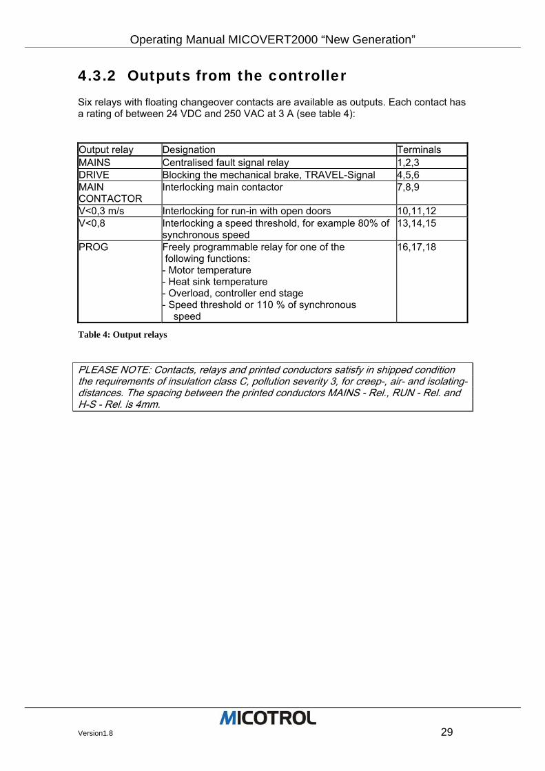
4.3.2 Outputs from the controller Six relays with floating changeover contacts are available as outputs. Each contact has a rating of between 24 VDC and 250 VAC at 3 A (see table 4): Output relay Designation Terminals MAINS Centralised fault signal relay 1,2,3 DRIVE Blocking the mechanical brake, TRAVEL-Signal 4,5,6 MAIN CONTACTOR
Interlocking main contactor 7,8,9
V<0,3 m/s Interlocking for run-in with open doors 10,11,12 V<0,8 Interlocking a speed threshold, for example 80% of
synchronous speed 13,14,15
PROG Freely programmable relay for one of the following functions: - Motor temperature - Heat sink temperature - Overload, controller end stage - Speed threshold or 110 % of synchronous speed
16,17,18
Table 4: Output relays
PLEASE NOTE: Contacts, relays and printed conductors satisfy in shipped condition the requirements of insulation class C, pollution severity 3, for creep-, air- and isolating-distances. The spacing between the printed conductors MAINS - Rel., RUN - Rel. and H-S - Rel. is 4mm.
Operating Manual MICOVERT 2000 “New Generation”
30 Version1.8
The outputs in detail:
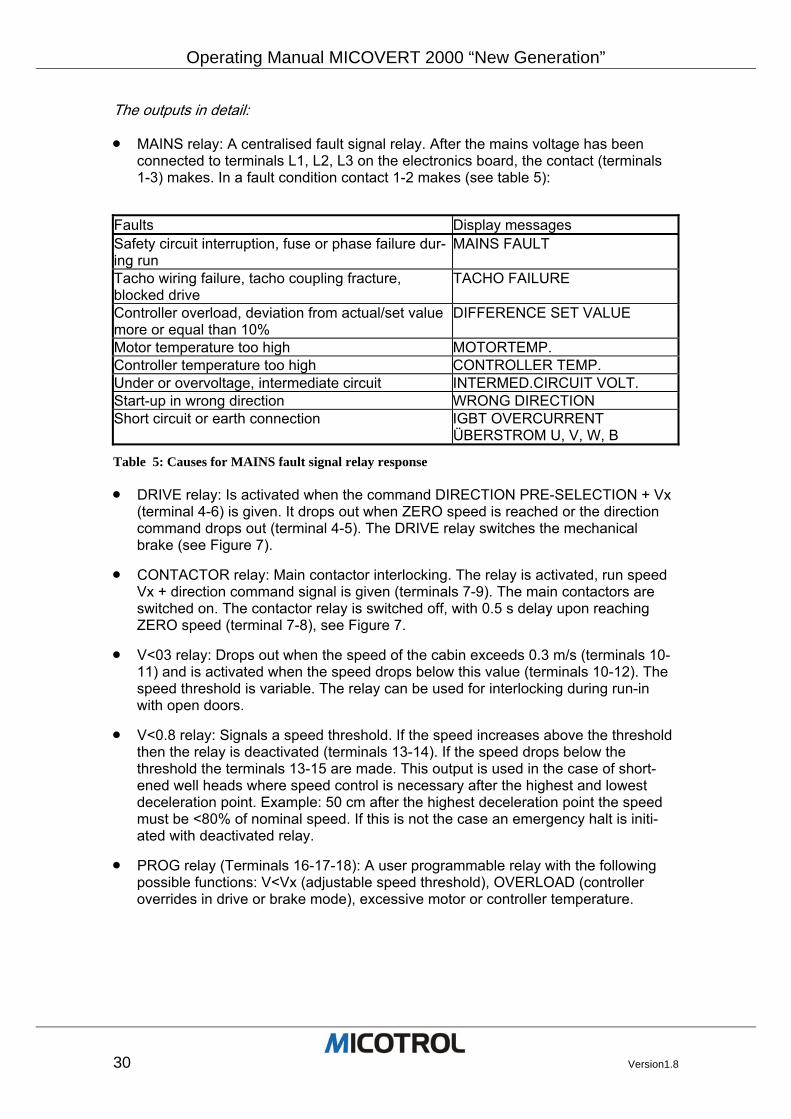
• MAINS relay: A centralised fault signal relay. After the mains voltage has been connected to terminals L1, L2, L3 on the electronics board, the contact (terminals 1-3) makes. In a fault condition contact 1-2 makes (see table 5):
Faults Display messages Safety circuit interruption, fuse or phase failure dur-ing run
MAINS FAULT
Tacho wiring failure, tacho coupling fracture, blocked drive
TACHO FAILURE
Controller overload, deviation from actual/set value more or equal than 10%
DIFFERENCE SET VALUE
Motor temperature too high MOTORTEMP. Controller temperature too high CONTROLLER TEMP. Under or overvoltage, intermediate circuit INTERMED.CIRCUIT VOLT. Start-up in wrong direction WRONG DIRECTION Short circuit or earth connection IGBT OVERCURRENT
ÜBERSTROM U, V, W, B
Table 5: Causes for MAINS fault signal relay response
• DRIVE relay: Is activated when the command DIRECTION PRE-SELECTION + Vx (terminal 4-6) is given. It drops out when ZERO speed is reached or the direction command drops out (terminal 4-5). The DRIVE relay switches the mechanical brake (see Figure 7).
• CONTACTOR relay: Main contactor interlocking. The relay is activated, run speed Vx + direction command signal is given (terminals 7-9). The main contactors are switched on. The contactor relay is switched off, with 0.5 s delay upon reaching ZERO speed (terminal 7-8), see Figure 7.
• V<03 relay: Drops out when the speed of the cabin exceeds 0.3 m/s (terminals 10-11) and is activated when the speed drops below this value (terminals 10-12). The speed threshold is variable. The relay can be used for interlocking during run-in with open doors.
• V<0.8 relay: Signals a speed threshold. If the speed increases above the threshold then the relay is deactivated (terminals 13-14). If the speed drops below the threshold the terminals 13-15 are made. This output is used in the case of short-ened well heads where speed control is necessary after the highest and lowest deceleration point. Example: 50 cm after the highest deceleration point the speed must be <80% of nominal speed. If this is not the case an emergency halt is initi-ated with deactivated relay.
• PROG relay (Terminals 16-17-18): A user programmable relay with the following possible functions: V<Vx (adjustable speed threshold), OVERLOAD (controller overrides in drive or brake mode), excessive motor or controller temperature.
Operating Manual MICOVERT2000 “New Generation”
Version1.8 31
4.4 Motor thermistor
The thermistor monitoring system is designed for three thermo sensors switched in a row as per DIN 44082 (terminals 19, 20 on controller). They are triggered at a resis-tance value of 2.7 kOhm. The controller is locked and the MAINS relay drops out (terminal 1-2). The cable must be shielded with the shield applied to terminal PE (be-sides 19, 20) on the controller and to PE on the motor. The system is automatically reset after the motor has cooled down. If a separate unit monitors motor temperature, terminals 19, 20 must be bridged.
4.5 Fault memory
If the controller identifies a fault, the MAINS, DRIVE and CONTACTOR relays will drop out immediately and a fault message will appear in the display. If all the run commands are switched off by the control system, the MAINS relay is re-activated and a new run can begin. If, in the event of a malfunction, one or more run commands remain on after the fault message is issued by the MAINS relay, the fault message will be saved until the run commands are switched off. The last 100 Faults will be saved in main menu ERROR.
Operating Manual MICOVERT 2000 “New Generation”
32 Version1.8
4.6 Brake resistor
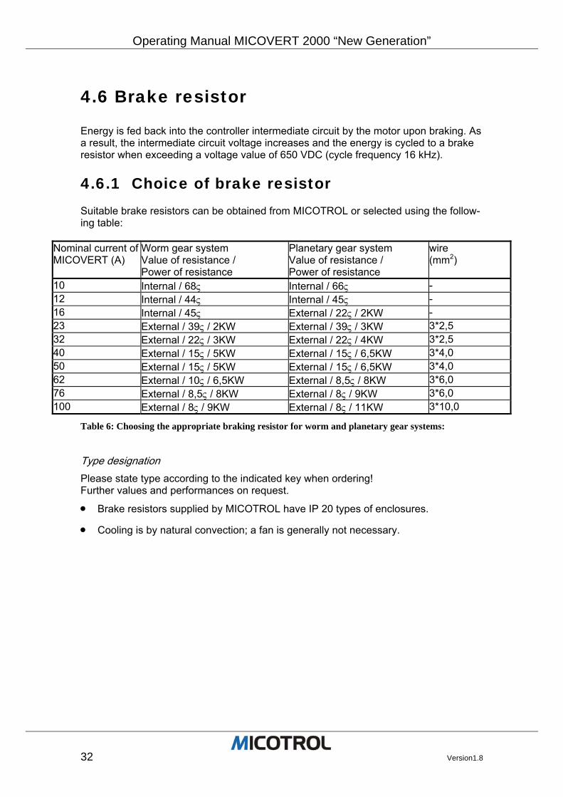
Energy is fed back into the controller intermediate circuit by the motor upon braking. As a result, the intermediate circuit voltage increases and the energy is cycled to a brake resistor when exceeding a voltage value of 650 VDC (cycle frequency 16 kHz).
4.6.1 Choice of brake resistor Suitable brake resistors can be obtained from MICOTROL or selected using the follow-ing table:
Nominal current of MICOVERT (A)
Worm gear system Value of resistance / Power of resistance
Planetary gear system Value of resistance / Power of resistance
wire (mm2)
10 Internal / 68ς Internal / 66ς - 12 Internal / 44ς Internal / 45ς - 16 Internal / 45ς External / 22ς / 2KW - 23 External / 39ς / 2KW External / 39ς / 3KW 3*2,5 32 External / 22ς / 3KW External / 22ς / 4KW 3*2,5 40 External / 15ς / 5KW External / 15ς / 6,5KW 3*4,0 50 External / 15ς / 5KW External / 15ς / 6,5KW 3*4,0 62 External / 10ς / 6,5KW External / 8,5ς / 8KW 3*6,0 76 External / 8,5ς / 8KW External / 8ς / 9KW 3*6,0 100 External / 8ς / 9KW External / 8ς / 11KW 3*10,0
Table 6: Choosing the appropriate braking resistor for worm and planetary gear systems:
Type designation Please state type according to the indicated key when ordering! Further values and performances on request.
• Brake resistors supplied by MICOTROL have IP 20 types of enclosures.
• Cooling is by natural convection; a fan is generally not necessary.
Operating Manual MICOVERT2000 “New Generation”
Version1.8 33
PLEASE NOTE: In case of gearless or V-belt systems, consult MICOTROL as different dimensioning will be necessary!
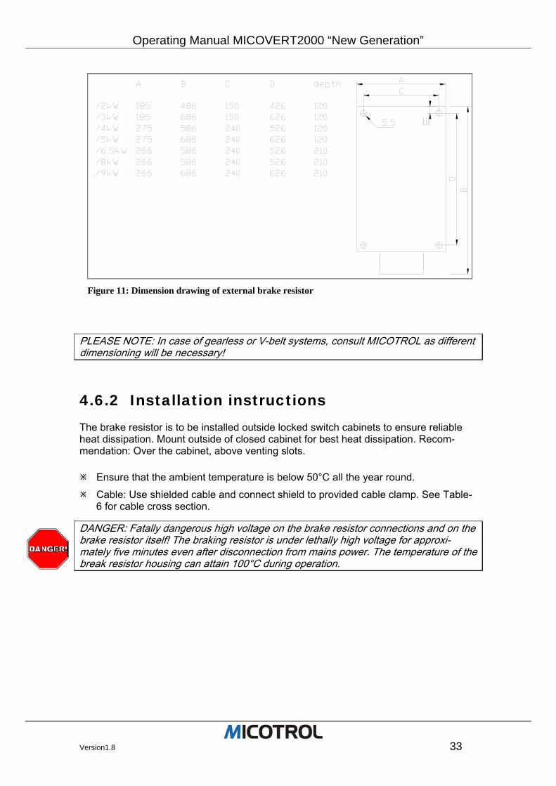
4.6.2 Installation instructions The brake resistor is to be installed outside locked switch cabinets to ensure reliable heat dissipation. Mount outside of closed cabinet for best heat dissipation. Recom-mendation: Over the cabinet, above venting slots.
Ensure that the ambient temperature is below 50°C all the year round.
Cable: Use shielded cable and connect shield to provided cable clamp. See Table-6 for cable cross section.
DANGER: Fatally dangerous high voltage on the brake resistor connections and on the brake resistor itself! The braking resistor is under lethally high voltage for approxi-mately five minutes even after disconnection from mains power. The temperature of the break resistor housing can attain 100°C during operation.
Figure 11: Dimension drawing of external brake resistor
Operating Manual MICOVERT 2000 “New Generation”
34 Version1.8
4.7 Shaft information
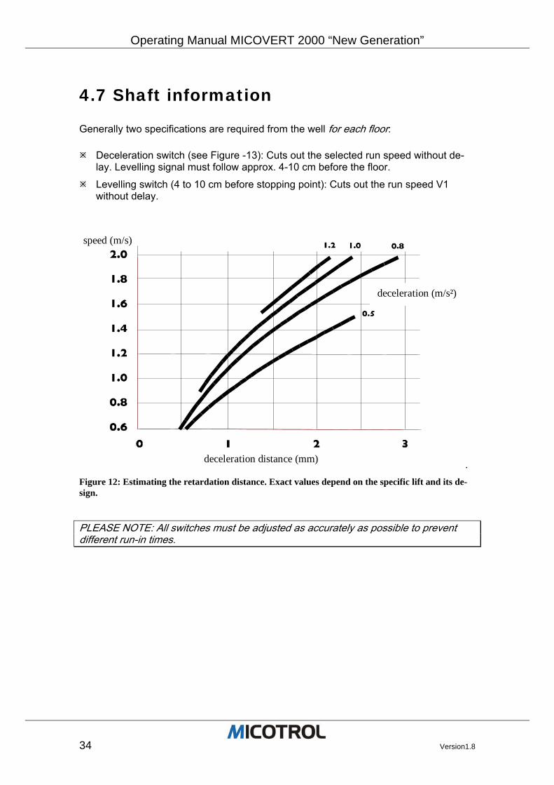
Generally two specifications are required from the well for each floor:
Deceleration switch (see Figure -13): Cuts out the selected run speed without de-lay. Levelling signal must follow approx. 4-10 cm before the floor.
Levelling switch (4 to 10 cm before stopping point): Cuts out the run speed V1 without delay.
deceleration distance (mm)
deceleration (m/s²)
speed (m/s)
. Figure 12: Estimating the retardation distance. Exact values depend on the specific lift and its de-sign.
PLEASE NOTE: All switches must be adjusted as accurately as possible to prevent different run-in times.
Operating Manual MICOVERT2000 “New Generation”
Version1.8 35
4.8 Serial interfaces
Two different fields of application are covered by the two different serial interfaces in the control system:
• MICOBUS: RS485/RS232 for use of a serial interface for the direct connection with the lift control system, i.e. LIFTBUS, RSI, DCP.
• PC-Interface: RS232 for Controller setting with the use of the MICOterminal or MI-COview via a laptop PC.
4.8.1 MICOBUS (optional) All input and output procedures can be realised through a serial interface (RS-232 or RS-485, standard Sub-D-connector on the front panel of the controller) (MICOBUS). Thus the controller can be connected directly to the control system without the usual control cables. The data transfer protocol must agree with that of the control system. Further informa-tion can be obtained by calling +49 (0) 6023 50 56 0.
PLEASE NOTE: Do not confuse this option with the PC control software described be-low!
4.8.2 Control system setting via PC With the help of a add-on unit MICOterminal or a add-on PC-terminal-software it is possible to make all control system settings can be made online. With this the build in display and the push buttons of the MICOVERT become unnecessary (MICOVERT 2001 / 2002). For this feature the standard RS232-PC-Interface is used. The necessary PC-Software or MICOterminal must be ordered separately. The delivery insist on the unit MICOterminal or the PC-Terminal-Software MICOview including the manual, in which operation and configuration between controller and PC is described in detail An interface cable for connecting the RS-232 interface of the usual commercial PC and the jack on the front plate of the controller can be supplied as an optional accessory.
Operating Manual MICOVERT 2000 “New Generation”
36 Version1.8
5 Menus and parameters
5.1 Preliminaries
5.2 Basic menu operation 5.2.1 Display, keypad, menus 5.2.2 Key functions 5.2.3 Switching on the controller 5.2.4 Menu structure
5.3 Menu descriptions 5.3.1 Main menu 5.3.2 SPEED menu 5.3.3 SPEED CURVE menu 5.3.4 START/STOP menu 5.3.5 DRIVE menu 5.3.6 INTERFACES menu 5.3.7 OPERATING PARAMETERS menu 5.3.8 CONTROLLER PARAMETERS menu
5.4 Monitor descriptions 5.4.1 MONITOR 1 5.4.2 MONITOR 2 5.4.3 MONITOR 3 5.4.4 MONITOR 4
5.5 Fault memory description Chapter overview: This chapter describes the first-time controller operation after installation: It covers the necessary preparations, describes the basic steps for programming the controller and provides detailed setting instructions. The commissioning technician learns how to ad-just the motor, lift control system and drive controller for smooth interaction.
Operating Manual MICOVERT2000 “New Generation”
Version1.8 37
5.1 Preliminaries
Before putting into operation for the first time you must: Make or check all connections and links to the motor, control system and encoder
(see Figure-7).
Insert the p.c. board and its cover (lacquer-coated front metal panel) inside the unit and screw in position after completing the installation and wiring work. There are no adjustments to make underneath the front panel!
Set all the shaft switches with a tolerance of no more than +/-3mm for the decelera-tion switch (fast/slow changeover switch or V3 to V1) and of no less than +/-1 mm for the levelling switch. The level signal must be given approximately 4 to 10 cm be-fore reaching floor level. It is important for the switch distances to be identical for each floor. The controller is unable to compensate differences from one floor to an-other!
To set the well switch distance as a function of the speed, see Figure-13
DANGER: A controller that is not yet properly adjusted can cause dangerous jerking of the cabin! Above all, during the adjustment work there is a risk of the lift setting off in the wrong direction.. This could cause serious injury to any persons inside the cabin! Make sure that no one can use the lift before and during commissioning and before the lift passes the official inspection test! If necessary, set up barriers and provide warning signs on each floor. In any case you must switch off the external door controller in the lift control system!
5.2 Basic menu operation
The adjustments are made step by step via the controller-operating panel. The basic options and structure of the operating menus are described below.
5.2.1 Display, keypad, menus The operating panel consists of a two-line LCD with two LEDs to the right and four keys below. Operations are based on various „entry masks“. The successive masks are called „menus“. You can move from one menu to another and make changes to the values listed in a menu. Menus are classified as main menus and sub-menus (for example FINAL SPEED. Main menus correspond to chapter headings which have various sub-chapters (for example FINAL SPEED V4).
Operating Manual MICOVERT 2000 “New Generation”
38 Version1.8
5.2.2 Key functions Key functions are identical for all menus, i.e.:
The arrow keys UP and DOWN:
• Selection of main menu • Selection of sub-menu • Changing of set values (parameters) as digits or ON/OFF
Use the right-hand key, ENTER:
• To move from the main menu into a sub-menu • To enter the „edit mode“ inside a sub-menu • To accept a changed set value (parameters) in the permanent memory
Use the left-hand key, QUIT:
• To move from „edit mode“ back into a sub-menu • To return from a sub-menu to the main menu • To navigate to another menu area using the selection menu
For convenient reference, the key functions are shown in the menu structure diagram printed on the front panel.
PLEASE NOTE: After you have changed a set value (parameter) you must press ENTER to permanently store the new value. Then the arrow in front of the set value, which indicates the editing mode, disappears. If ENTER is not pressed or if QUIT is pressed the original (default factory) values will be used.
5.2.3 Switching on the controller
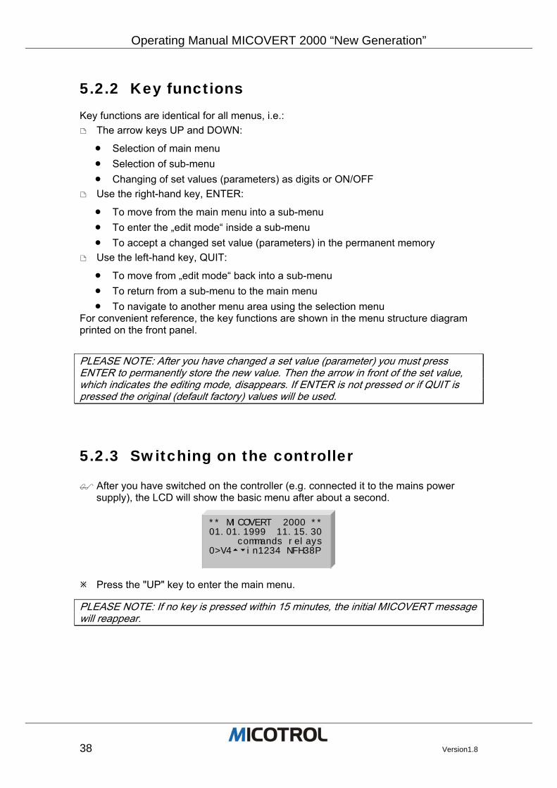
After you have switched on the controller (e.g. connected it to the mains power supply), the LCD will show the basic menu after about a second.
Press the "UP" key to enter the main menu.
PLEASE NOTE: If no key is pressed within 15 minutes, the initial MICOVERT message will reappear.
** MICOVERT 2000 **01.01.1999 11.15.30 commands relays0>V4tuin1234 NFH38P
Operating Manual MICOVERT2000 “New Generation”
Version1.8 39
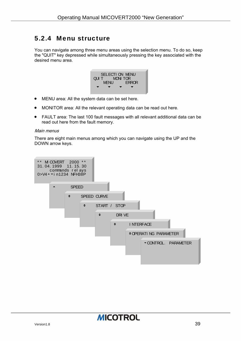
5.2.4 Menu structure You can navigate among three menu areas using the selection menu. To do so, keep the "QUIT" key depressed while simultaneously pressing the key associated with the desired menu area.
• MENU area: All the system data can be set here.
• MONITOR area: All the relevant operating data can be read out here.
• FAULT area: The last 100 fault messages with all relevant additional data can be read out here from the fault memory.
Main menus There are eight main menus among which you can navigate using the UP and the DOWN arrow keys.
SELECTION MENU QUIT MONITOR MENU ERROR u u u u
** MICOVERT 2000 ** 31.04.1999 11.15.30 commands relays 0>V4tuin1234 NFH38P
t SPEED
v SPEED CURVE
v START / STOP
v DRIVE � � �
v INTERFACE � � �
vOPERATING PARAMETER � � �
uCONTROL. PARAMETER
Operating Manual MICOVERT 2000 “New Generation”
40 Version1.8
Sub-menus
For navigating from the main menu to the sub-menus to change set values, use the pushbutton “ENTER”.
For navigating among the main menus and changing set values, use the pushbut-tons “UP” and “DOWN”.
Changing data in sub-menus: Move from the display into the edit mode using ENTER, change the values using the arrow keys and press ENTER to save per-manently.
PLEASE NOTE: Parameter changes can only be carried out, if no travel commands are applied, i.e. the lift is at standstill.
5.3 Menu descriptions
The following sections describe all the adjustment steps needed to put the controller and the drive into operation. Although the controller is set in the factory with default values taken from practice, it is still essential for you to go through the individual ad-justment steps since some specific values will certainly need to be adjusted (e.g. the motor parameters).
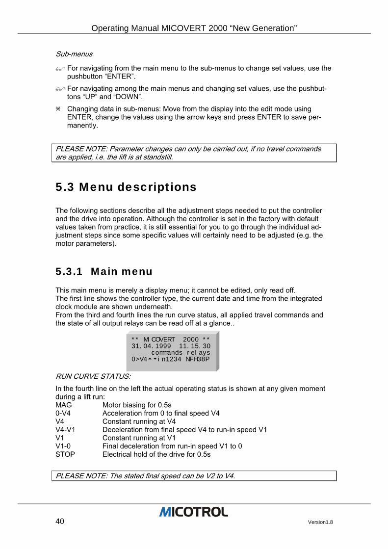
5.3.1 Main menu This main menu is merely a display menu; it cannot be edited, only read off. The first line shows the controller type, the current date and time from the integrated clock module are shown underneath. From the third and fourth lines the run curve status, all applied travel commands and the state of all output relays can be read off at a glance..
RUN CURVE STATUS: In the fourth line on the left the actual operating status is shown at any given moment during a lift run: MAG Motor biasing for 0.5s 0-V4 Acceleration from 0 to final speed V4 V4 Constant running at V4 V4-V1 Deceleration from final speed V4 to run-in speed V1 V1 Constant running at V1 V1-0 Final deceleration from run-in speed V1 to 0 STOP Electrical hold of the drive for 0.5s
PLEASE NOTE: The stated final speed can be V2 to V4.
** MICOVERT 2000 **31.04.1999 11.15.30 commands relays0>V4tuin1234 NFH38P
Operating Manual MICOVERT2000 “New Generation”
Version1.8 41
TRAVEL COMMANDS In the middle of the fourth line the commands from control system are shown, for ex-ample t 1 3 (i. e. UP, V3, V1).
OUTPUT RELAYS On the right side of the fourth line the current state of the six output relays are shows: N MAINS relay has picked up F DRIVE relay has picked up H CONTACTOR relay has picked up 3 Relay V<03 has picked up 8 Relay V<08 has picked up P Programmable relay has picked up
Operating Manual MICOVERT 2000 “New Generation”
42 Version1.8
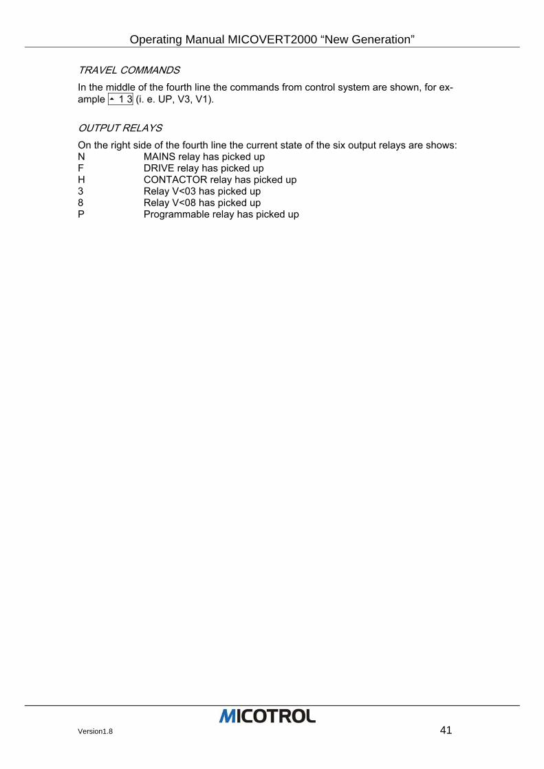
5.3.2 SPEED menu The MICOVERT controller has a total of six different speeds (see Figure 12). [Adjustment speed Vn] Adjustment speed, variable from 0.5 to 100r.p.m. Is set
so that the lift stops in level position after adjustment (only command Vn). Is used in the case of considerable rope elongation after which the cabin is no longer level after unloading. Requires an additional level flag that is shorter than that of V1.
[Inspection speed Vi] Inspection speed, variable from 10 to 1500r.p.m. Set as required
for inspection runs on the cabin roof and for returning the lift to its starting po-sition.
[Run-in speed V1] Run-in speed, variable from 1 to 100r.p.m. Set so that the
lift stops level: If it stops too soon, V1 must be increased; if the cabin moves too far, V1 must be decreased. See chapter 6.3.3 for details of how to set the stopping accuracy via V1.
t SPEED
SPEED t adjustmt. speed Vn 0007.5rpm 0.01m/s
SPEED vinspection speed Vi 0225.0rpm 0.30m/s
SPEED v run-in speed V1 0075.0rpm 0.10m/s
SPEED v interim speed V2 0750.0rpm 1.00m/s
SPEED v final speed V3 1250.0rpm 1.66m/s
SPEED u final speed V4 1450.0rpm 1.93m/s
Operating Manual MICOVERT2000 “New Generation”
Version1.8 43
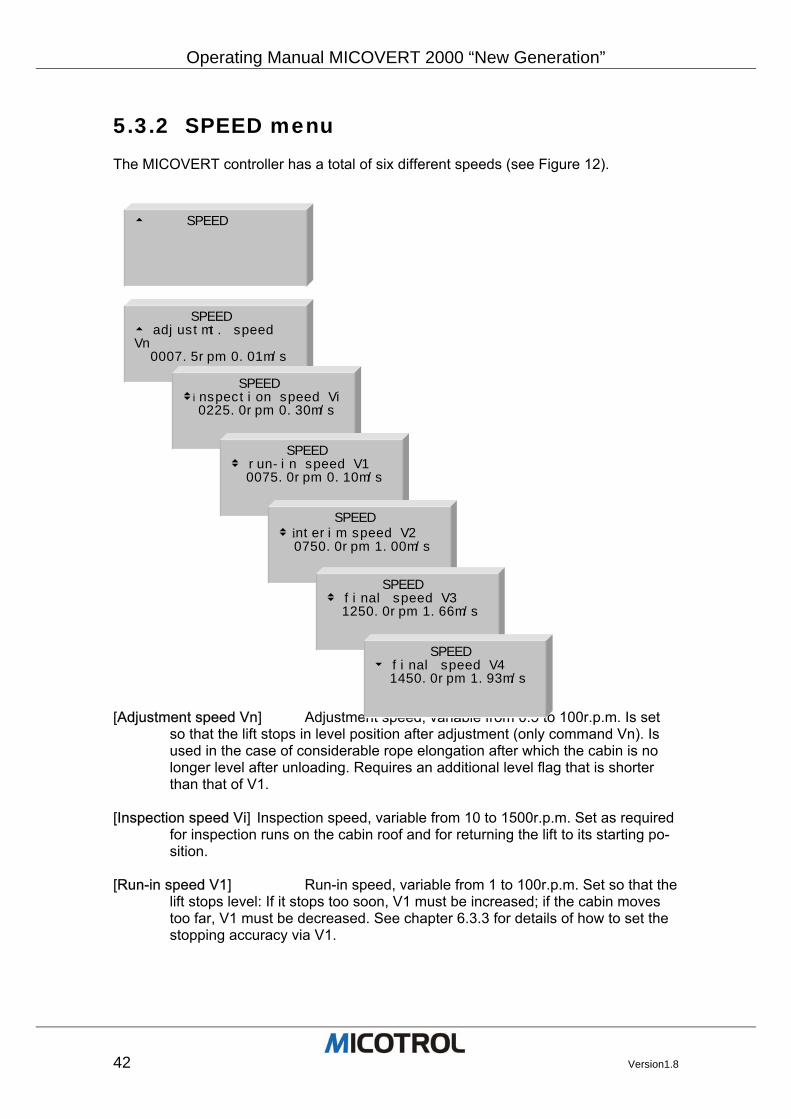
[Interim speed V2] Interim speed, variable from 10 to 3000r.p.m. Is only used when there are different braking distances in the well, i.e. when the dis-tances from the floor switch (=deceleration point) to the levelling switch vary. After calibration of the V2 braking distance it is advisable to set V2 as high as possible; caution: BRAKING PATH V2.
[Final speed V3] Final speed, variable from 10 to 3000r.p.m. [Final speed V4] Alternative final speed, variable from 10 to 3000r.p.m. If
necessary increase V4 until OVERLOAD CONTROL appears in the display.
Figure 13: Using different speed commands.
Operating Manual MICOVERT 2000 “New Generation”
44 Version1.8
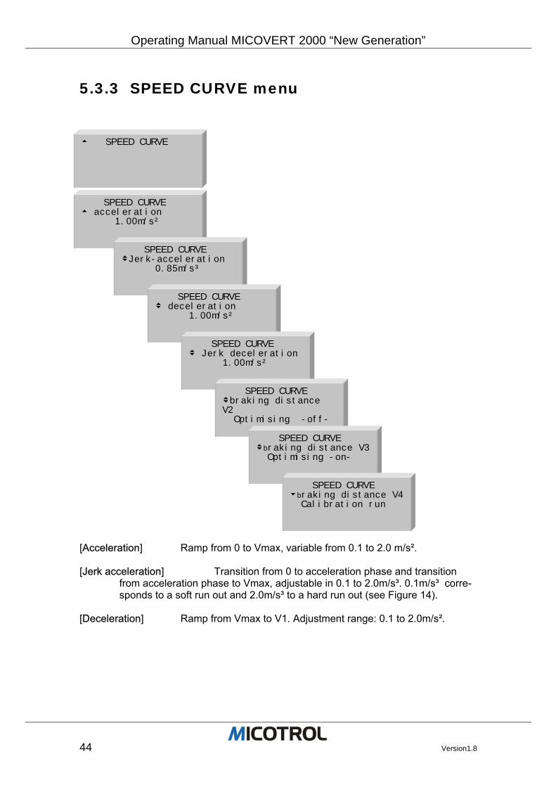
5.3.3 SPEED CURVE menu
[Acceleration] Ramp from 0 to Vmax, variable from 0.1 to 2.0 m/s². [Jerk acceleration] Transition from 0 to acceleration phase and transition
from acceleration phase to Vmax, adjustable in 0.1 to 2.0m/s³. 0.1m/s³ corre-sponds to a soft run out and 2.0m/s³ to a hard run out (see Figure 14).
[Deceleration] Ramp from Vmax to V1. Adjustment range: 0.1 to 2.0m/s².
t SPEED CURVE
SPEED CURVE t acceleration 1.00m/s²
SPEED CURVE vJerk-acceleration 0.85m/s³
SPEED CURVE v deceleration 1.00m/s²
SPEED CURVE v Jerk deceleration 1.00m/s²
SPEED CURVE vbraking distance V2 Optimising -off-
SPEED CURVE vbraking distance V3 Optimising -on-
SPEED CURVE ubraking distance V4 Calibration run
Operating Manual MICOVERT2000 “New Generation”
Version1.8 45
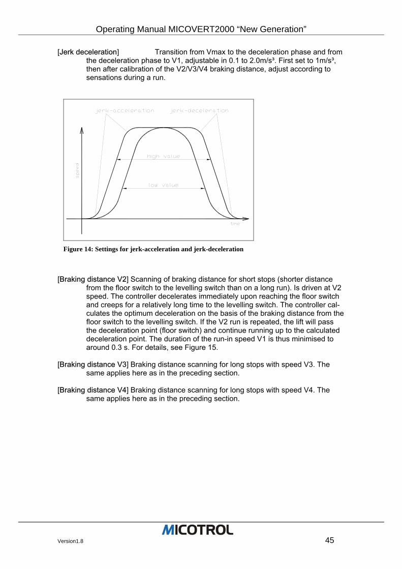
[Jerk deceleration] Transition from Vmax to the deceleration phase and from the deceleration phase to V1, adjustable in 0.1 to 2.0m/s³. First set to 1m/s³, then after calibration of the V2/V3/V4 braking distance, adjust according to sensations during a run.
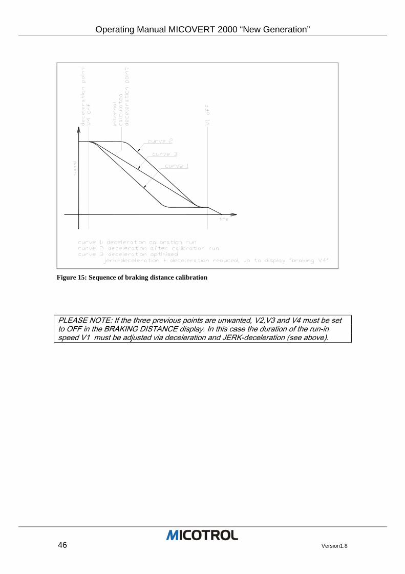
[Braking distance V2] Scanning of braking distance for short stops (shorter distance
from the floor switch to the levelling switch than on a long run). Is driven at V2 speed. The controller decelerates immediately upon reaching the floor switch and creeps for a relatively long time to the levelling switch. The controller cal-culates the optimum deceleration on the basis of the braking distance from the floor switch to the levelling switch. If the V2 run is repeated, the lift will pass the deceleration point (floor switch) and continue running up to the calculated deceleration point. The duration of the run-in speed V1 is thus minimised to around 0.3 s. For details, see Figure 15.
[Braking distance V3] Braking distance scanning for long stops with speed V3. The
same applies here as in the preceding section. [Braking distance V4] Braking distance scanning for long stops with speed V4. The
same applies here as in the preceding section.
Figure 14: Settings for jerk-acceleration and jerk-deceleration
Operating Manual MICOVERT 2000 “New Generation”
46 Version1.8
PLEASE NOTE: If the three previous points are unwanted, V2,V3 and V4 must be set to OFF in the BRAKING DISTANCE display. In this case the duration of the run-in speed V1 must be adjusted via deceleration and JERK-deceleration (see above).
Figure 15: Sequence of braking distance calibration
Operating Manual MICOVERT2000 “New Generation”
Version1.8 47
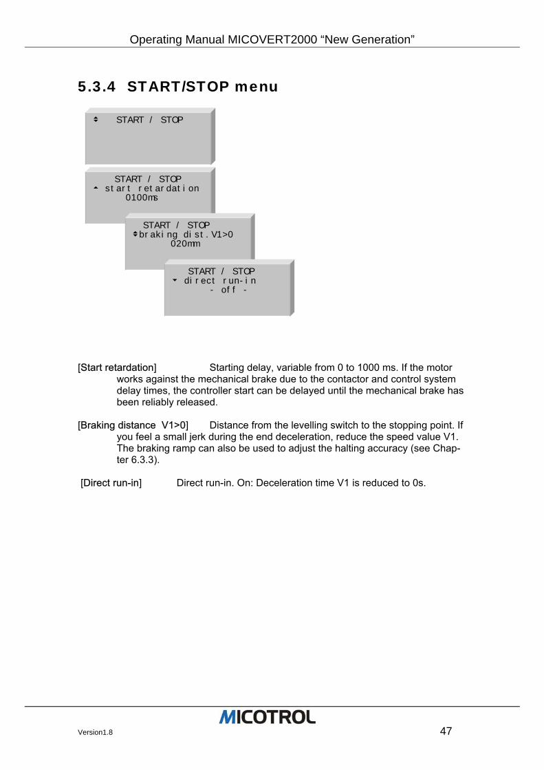
5.3.4 START/STOP menu
[Start retardation] Starting delay, variable from 0 to 1000 ms. If the motor
works against the mechanical brake due to the contactor and control system delay times, the controller start can be delayed until the mechanical brake has been reliably released.
[Braking distance V1>0] Distance from the levelling switch to the stopping point. If
you feel a small jerk during the end deceleration, reduce the speed value V1. The braking ramp can also be used to adjust the halting accuracy (see Chap-ter 6.3.3).
[Direct run-in] Direct run-in. On: Deceleration time V1 is reduced to 0s.
v START / STOP
START / STOP t start retardation 0100ms
START / STOP vbraking dist.V1>0 020mm
START / STOP u direct run-in - off -
Operating Manual MICOVERT 2000 “New Generation”
48 Version1.8
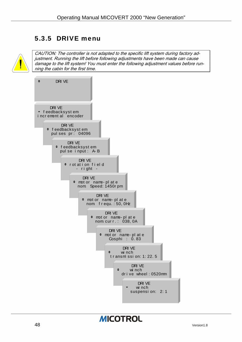
5.3.5 DRIVE menu
CAUTION: The controller is not adapted to the specific lift system during factory ad-justment. Running the lift before following adjustments have been made can cause damage to the lift system! You must enter the following adjustment values before run-ning the cabin for the first time.
v DRIVE
DRIVE t feedbacksystem incremental encoder
DRIVE v feedbacksystem pulses pr: 04096
DRIVE v feedbacksystem pulse input: A-B DRIVE
v rotation field - right -
DRIVE v motor name-plate nom. Speed:1450rpm
DRIVE v motor name-plate nom. frequ.:50,0Hz
DRIVE v motor name-plate nom.curr.: 038,0A
DRIVE v motor name-plate Cosphi : 0.83
DRIVE v winch transmission:1:22.5
DRIVE v winch drive wheel:0520mm
DRIVE u winch suspension: 2:1
Operating Manual MICOVERT2000 “New Generation”
Version1.8 49
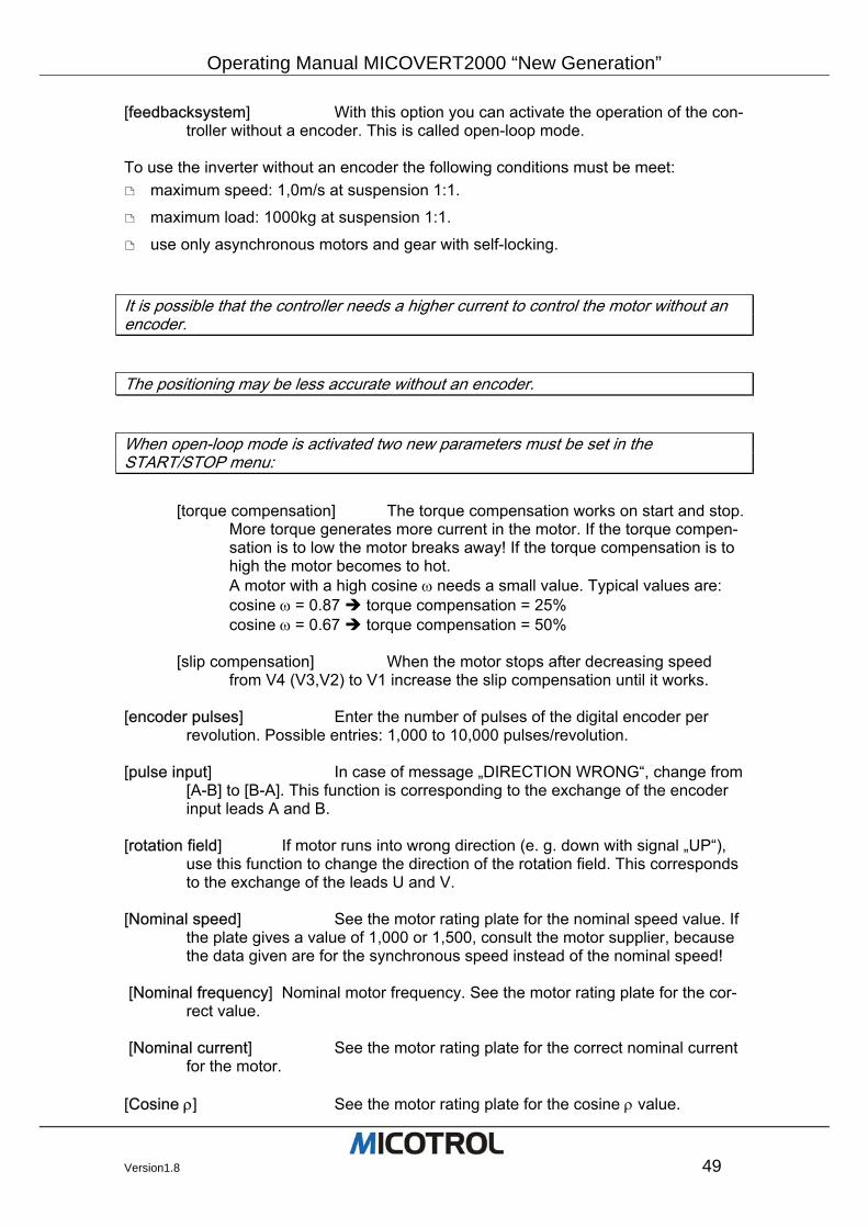
[feedbacksystem] With this option you can activate the operation of the con-troller without a encoder. This is called open-loop mode.
To use the inverter without an encoder the following conditions must be meet:
maximum speed: 1,0m/s at suspension 1:1.
maximum load: 1000kg at suspension 1:1.
use only asynchronous motors and gear with self-locking.
It is possible that the controller needs a higher current to control the motor without an encoder.
The positioning may be less accurate without an encoder.
When open-loop mode is activated two new parameters must be set in the START/STOP menu:
[torque compensation] The torque compensation works on start and stop.
More torque generates more current in the motor. If the torque compen-sation is to low the motor breaks away! If the torque compensation is to high the motor becomes to hot. A motor with a high cosine ω needs a small value. Typical values are: cosine ω = 0.87 torque compensation = 25% cosine ω = 0.67 torque compensation = 50%
[slip compensation] When the motor stops after decreasing speed
from V4 (V3,V2) to V1 increase the slip compensation until it works. [encoder pulses] Enter the number of pulses of the digital encoder per
revolution. Possible entries: 1,000 to 10,000 pulses/revolution. [pulse input] In case of message „DIRECTION WRONG“, change from
[A-B] to [B-A]. This function is corresponding to the exchange of the encoder input leads A and B.
[rotation field] If motor runs into wrong direction (e. g. down with signal „UP“),
use this function to change the direction of the rotation field. This corresponds to the exchange of the leads U and V.
[Nominal speed] See the motor rating plate for the nominal speed value. If
the plate gives a value of 1,000 or 1,500, consult the motor supplier, because the data given are for the synchronous speed instead of the nominal speed!
[Nominal frequency] Nominal motor frequency. See the motor rating plate for the cor-
rect value. [Nominal current] See the motor rating plate for the correct nominal current
for the motor. [Cosine ρ] See the motor rating plate for the cosine ρ value.
Operating Manual MICOVERT 2000 “New Generation”
50 Version1.8
[transmission] Enter the gear ratio. See the gearbox rating plate for the
correct value. [drive wheel] Enter drive pulley diameter in (mm). [suspension] Enter rope suspension (e.g. 1:1 or 2:1).
Operating Manual MICOVERT2000 “New Generation”
Version1.8 51
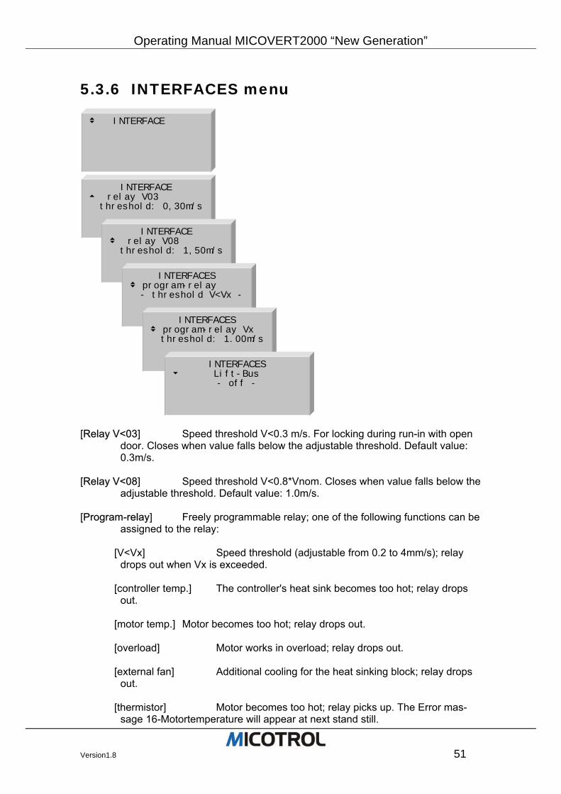
5.3.6 INTERFACES menu
[Relay V<03] Speed threshold V<0.3 m/s. For locking during run-in with open
door. Closes when value falls below the adjustable threshold. Default value: 0.3m/s.
[Relay V<08] Speed threshold V<0.8*Vnom. Closes when value falls below the
adjustable threshold. Default value: 1.0m/s. [Program-relay] Freely programmable relay; one of the following functions can be
assigned to the relay:
[V<Vx] Speed threshold (adjustable from 0.2 to 4mm/s); relay drops out when Vx is exceeded.
[controller temp.] The controller's heat sink becomes too hot; relay drops
out.
[motor temp.] Motor becomes too hot; relay drops out.
[overload] Motor works in overload; relay drops out.
[external fan] Additional cooling for the heat sinking block; relay drops out.
[thermistor] Motor becomes too hot; relay picks up. The Error mas-
sage 16-Motortemperature will appear at next stand still.
v INTERFACE
INTERFACE t relay V03 threshold: 0,30m/s INTERFACE
v relay V08 threshold: 1,50m/s
INTERFACES v program-relay - threshold V<Vx - INTERFACES
v program-relay Vx threshold: 1.00m/s INTERFACES
u Lift-Bus - off -
Operating Manual MICOVERT 2000 “New Generation”
52 Version1.8
[Lift-Bus] This parameter selects the following steering options:
[off] commands via terminal; standard.
[DCP3-(RS485)] Inverter commands via DCP3 protocol. This protocol is a replacement for terminal commands. The Inverter commands will be transmit-ted over the RS485 connection. Please note the initialisation information of the lift-controller manufacturer.
[DCP4-(RS485)] Inverter commands via DCP4 protocol. This protocol of-
fers a time- and speed-optimised run of lift, because the lift-controller delivers the absolute well position of the car. So the MICOVERT can compute the op-timal speed and directly run in to the storey. Please note the initialisation information of the lift-controller manufacturer.
PLEASE NOTE: When using DCP protocol, the information of the programmable relay is used as over-speed signal by the lift controller. So the lift will be disabled when this signal occurs.
Set the function of the programmable relay to [V<Vx] and the threshold Vx higher than the nominal speed of the lift.
PLEASE NOTE: To use the DCP3 and DCP4 protocol a special display-card is needed, with a RS485 Interface. Please state this with your order.
Operating Manual MICOVERT2000 “New Generation”
Version1.8 53
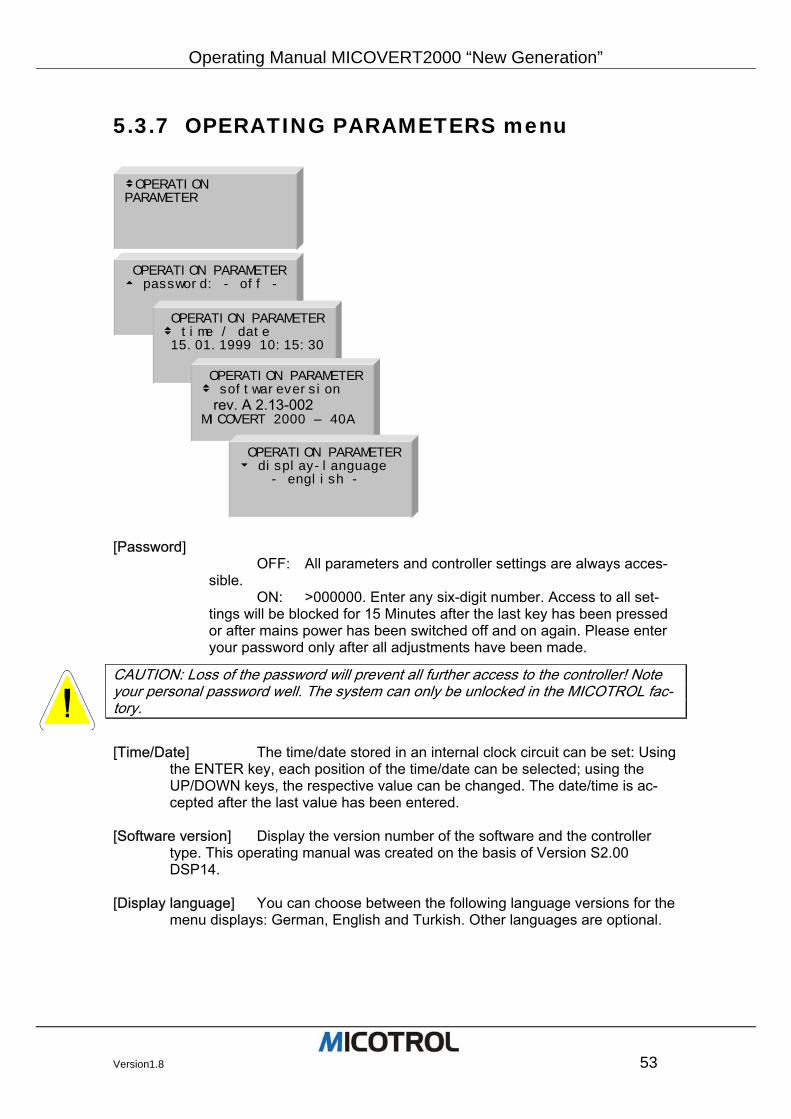
5.3.7 OPERATING PARAMETERS menu
[Password]
OFF: All parameters and controller settings are always acces-sible.
ON: >000000. Enter any six-digit number. Access to all set-tings will be blocked for 15 Minutes after the last key has been pressed or after mains power has been switched off and on again. Please enter your password only after all adjustments have been made.
CAUTION: Loss of the password will prevent all further access to the controller! Note your personal password well. The system can only be unlocked in the MICOTROL fac-tory.
[Time/Date] The time/date stored in an internal clock circuit can be set: Using
the ENTER key, each position of the time/date can be selected; using the UP/DOWN keys, the respective value can be changed. The date/time is ac-cepted after the last value has been entered.
[Software version] Display the version number of the software and the controller
type. This operating manual was created on the basis of Version S2.00 DSP14.
[Display language] You can choose between the following language versions for the
menu displays: German, English and Turkish. Other languages are optional.
vOPERATION PARAMETER
OPERATION PARAMETER t password: - off - OPERATION PARAMETER
v time / date 15.01.1999 10:15:30
OPERATION PARAMETERv softwareversion rev. A 2.13-002 MICOVERT 2000 – 40A
OPERATION PARAMETERu display-language - english -
Operating Manual MICOVERT 2000 “New Generation”
54 Version1.8
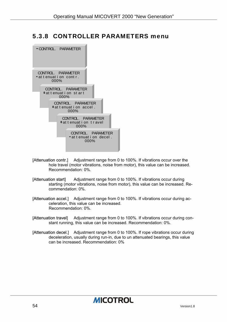
5.3.8 CONTROLLER PARAMETERS menu
[Attenuation contr.] Adjustment range from 0 to 100%. If vibrations occur over the
hole travel (motor vibrations, noise from motor), this value can be increased. Recommendation: 0%.
[Attenuation start] Adjustment range from 0 to 100%. If vibrations occur during
starting (motor vibrations, noise from motor), this value can be increased. Re-commendation: 0%.
[Attenuation accel.] Adjustment range from 0 to 100%. If vibrations occur during ac-
celeration, this value can be increased. Recommendation: 0%.
[Attenuation travel] Adjustment range from 0 to 100%. If vibrations occur during con-
stant running, this value can be increased. Recommendation: 0%. [Attenuation decel.] Adjustment range from 0 to 100%. If rope vibrations occur during
deceleration, usually during run-in, due to un attenuated bearings, this value can be increased. Recommendation: 0%
uCONTROL. PARAMETER
CONTROL. PARAMETER tattenuation contr. 000%
CONTROL. PARAMETER vattenuation start 000%
CONTROL. PARAMETER vattenuation accel. 000%
CONTROL. PARAMETER vattenuation travel 000%
CONTROL. PARAMETER uattenuation decel. 000%
Operating Manual MICOVERT2000 “New Generation”
Version1.8 55
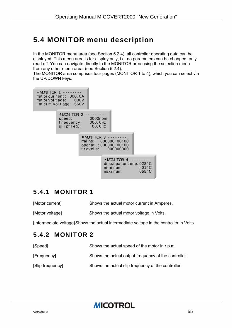
5.4 MONITOR menu description
In the MONITOR menu area (see Section 5.2.4), all controller operating data can be displayed. This menu area is for display only, i.e. no parameters can be changed, only read off. You can navigate directly to the MONITOR area using the selection menu from any other menu area. (see Section 5.2.4). The MONITOR area comprises four pages (MONITOR 1 to 4), which you can select via the UP/DOWN keys.
5.4.1 MONITOR 1 [Motor current] Shows the actual motor current in Amperes. [Motor voltage] Shows the actual motor voltage in Volts. [Intermediate voltage] Shows the actual intermediate voltage in the controller in Volts.
5.4.2 MONITOR 2 [Speed] Shows the actual speed of the motor in r.p.m. [Frequency] Shows the actual output frequency of the controller. [Slip frequency] Shows the actual slip frequency of the controller.
tMONITOR 1 -------- motorcurrent: 000,0A motorvoltage: 000V interm.voltage: 560V
vMONITOR 2 -------- speed: 0000rpmfrequency: 000,0Hzslipfreq.: 00,0Hz
vMONITOR 3 -------- mains: 000000:00:00operat.:000000:00:00travels: 000000000
uMONITOR 4 -------- dissipatortemp:028°Cminimum: -01°Cmaximum: 055°C
Operating Manual MICOVERT 2000 “New Generation”
56 Version1.8
5.4.3 MONITOR 3 [Mains] Shows the time in hours, minutes and seconds in which
the controller was switched on (i.e. connected to mains power). [Operating] Shows the time in hours, minutes and seconds in which
the controller was in operation. [Travels] Run counter, shows the number of all runs.
5.4.4 MONITOR 4 [Dissipater temp.] Shows the controller heat sink / power transistor tem-
perature. Should be under 75°C during normal operation. [minimum] Minimum value memory: Shows the minimum controller
heat sink / power transistor temperature. [maximum] Maximum value memory: Shows the maximum controller
heat sink / power transistor temperature.
Operating Manual MICOVERT2000 “New Generation”
Version1.8 57
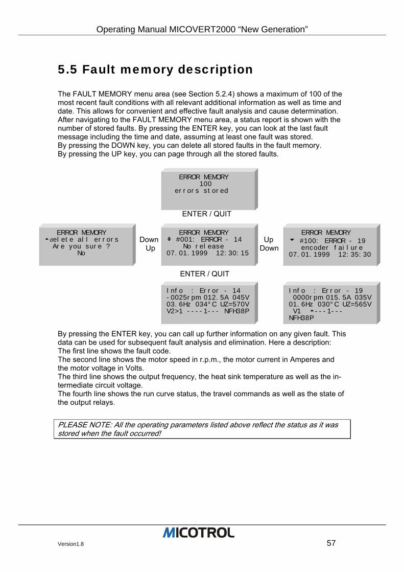
5.5 Fault memory description
The FAULT MEMORY menu area (see Section 5.2.4) shows a maximum of 100 of the most recent fault conditions with all relevant additional information as well as time and date. This allows for convenient and effective fault analysis and cause determination. After navigating to the FAULT MEMORY menu area, a status report is shown with the number of stored faults. By pressing the ENTER key, you can look at the last fault message including the time and date, assuming at least one fault was stored. By pressing the DOWN key, you can delete all stored faults in the fault memory. By pressing the UP key, you can page through all the stored faults. ENTER / QUIT Down Up Up Down
ENTER / QUIT By pressing the ENTER key, you can call up further information on any given fault. This data can be used for subsequent fault analysis and elimination. Here a description: The first line shows the fault code. The second line shows the motor speed in r.p.m., the motor current in Amperes and the motor voltage in Volts. The third line shows the output frequency, the heat sink temperature as well as the in-termediate circuit voltage. The fourth line shows the run curve status, the travel commands as well as the state of the output relays.
PLEASE NOTE: All the operating parameters listed above reflect the status as it was stored when the fault occurred!
ERROR MEMORY 100 errors stored
ERROR MEMORY tdelete all errors Are you sure ? No
ERROR MEMORY v #001: ERROR - 14 No release 07.01.1999 12:30:15
ERROR MEMORY u #100: ERROR - 19 encoder failure 07.01.1999 12:35:30
Info : Error - 19 0000rpm 015.5A 035V01.6Hz 030°C UZ=565V V1 t---1--- NFH38P
Info : Error - 14 -0025rpm 012.5A 045V03.6Hz 034°C UZ=570VV2>1 ----1--- NFH38P
Operating Manual MICOVERT 2000 “New Generation”
58 Version1.8
6 Putting into operation
6.1 Preparations 6.1.1 Summary of installation instructions 6.1.2 Checking the installation
6.2 Entry of main data 6.2.1 Switching on the controller 6.2.2 Entering the motor parameters 6.2.3 Entering inspection speed 6.3.4 Inspection run
6.3 Commissioning, normal run 6.3.1 Test run 6.3.2 Calibration run 6.3.3 Setting the stopping accuracy 6.3.4 Checking the braking path 6.3.5 Checking the stopping accuracy 6.3.6 Starting behaviour
6.4 Inspection run
6.5 Setting V2 and V3
6.6 Direct run-in Chapter overview: This chapter describes how to put the controller into operation for the first time, needed preparations and conditions and how to check the connections. After the converter has been adjusted, the inspection and normal run follows as well as the direct run-in tests.
Operating Manual MICOVERT2000 “New Generation”
Version1.8 59
6.1 Preparations
6.1.1 Summary of installation instructions
Installing the controller
Shielded cables must be used for the encoder lines and for any other encoders. Connect the cable shield of the external encoder to PE and to the corresponding separate shielding terminal on the controller's terminal strip.
The ambient temperature in the control cabinet must not exceed 45°C.
Be sure to remove the waste heat from the controller! Provide adequate ventilation!
Connecting the controller Connect the controller as per terminal diagram (see Figure 7). To do so, remove the metal cover by loosening the front screws. Important details:
Following cables must be shielded: Motor cable, breaking-resistor cable, encoder cable und thermistor cable. Shield: Copper braiding, both sides connected to PE. There are special PE termi-nals at controller side.
Fuses: Use only low voltage HRC fuses. The nominal fuse current must be no higher than double the nominal controller current.
Check the mains voltage and nominal current (controller rating plate and the motor rating plate!).
Speed default: Check that the control voltages in the control system and controller (rating plate) for conformance.
Meanings of the various speed signals see Figure-12 (run diagram).
Release signal: The release signal (=UP or DOWN) must be given with each run command and must not be switched off again until about 1 second after standstill is reached! EXCEPTION: On an inspection run the RELEASE signal must be switched off immediately.
Main contactor and direction contactor: Actuated directly via CONTACTOR output relay; delayed after end of run. Never switch on main contactor jointly with the main switch!
CAUTION: Destruction of converter, if main contactor is not properly activated! Ensure that the inverter p.c. board (terminals L1, L2, L3) is connected to mains voltage before the main contactor is activated.
DRIVE relay: If the controller lets the DRIVE relay drop out after the end of a run, the electromagnetic brake must be applied immediately by the control system.
MAINS relay: Fault signal for mains failure, fuse failure, under voltage, temperature too high, encoder broken.
Motor contactor: If no PTC thermistor is provided, terminals 19/20 must be bridged.
Operating Manual MICOVERT 2000 “New Generation”
60 Version1.8
6.1.2 Checking the installation You must carry out the following test steps before start-up:
Make all connections to the motor, control system and encoder or check same, re-spectively.
The shielding of the motor supply cable and brake resistance cable must be applied on both sides over a large area from the cable clip on motor housing to the cable clip on the controller.
As a general rule shielded leads must be used for analog and digital encoders. The encoder shielding must be connected to both sides: On the motor side directly to the housing (PE), on the controller side to terminal 31 (capacitor for PE). Leads not in use must be connected on both sides to the protective conductor!
Check the controller connections: Compare the following data with the values given on the controller rating plate:
• Mains voltage • Motor capacity/motor nominal current • Control voltage
Check the brake resistor: Check type, rating and resistance value!
After installation and wiring, insert the p.c. board and the p.c. board cover (var-nished sheet metal front cover) into the controller and fasten with screws. No more adjustments are to be made behind the front panel!
DANGER: High voltages dangerous to life! Through the buffering of the intermediate circuit capacitors some components are still under high voltage for at least five minutes even after the mains power supply has been switched off. The front cover must be folded in and fastened by screws during and after starting up the controller and when it is in operation.!
Set all shaft switches with an accuracy of max +/- 5 mm for the deceleration switch (switchover switch from fast/slow or V3 to V1, respectively) with an accuracy of min. +/- 2 mm for the levelling switches. The levelling signal must be given approx. 4 - 10 cm before reaching the floor level. It is essential that the switch distances are identical for each floor. The controller cannot compensate differences from floor to floor.
PLEASE NOTE: To set the distance for the shaft switch dependent on the travel speed, see Figure-11.
Check whether the motor/drive unit with encoder and mechanical brake and the brake resistor are installed and wired correctly (shielding!).
You must be familiar with the operation and use of the controller keypad and dis-play. Should you have any questions, please read Chapter 5!
Operating Manual MICOVERT2000 “New Generation”
Version1.8 61
DANGER: Dangerous jolting of the cabin can occur if the converter has not been ad-justed. Ensure that the lift cannot be used by persons before and during start and until it has been approved by the appropriate authorities. If necessary, barriers and warning signs must be provided on each floor. Moreover, under all circumstances the external door control system must be switched off through the lift control system!
6.2 Entry of main data
6.2.1 Switching on the controller
After the controller has been switched on (i.e. connection has been made to the mains power supply), the controller performs a self-test and the LC display shows the main menu with the status of all inputs and outputs as well as the time and date from the internal clock circuit.
6.2.2 Entering the motor parameters
CAUTION: The drive and the controller can be damaged through false initial settings! You must proceed and go through the following setting steps before the first run!
Go to the DRIVE main menu.
Read the pulse count from the encoder rating plate or from the encoder specifica-tion and enter this in the DIGITAL ENCODER PULSE sub-menu.
Read the motor nominal speed from the motor rating plate and enter in the NOMINAL SPEED sub-menu.
Read the motor nominal current (A) from the motor rating plate and enter in the NOMINAL CURRENT sub-menu.
Read the cosine ρ from the motor rating plate and enter in the COSINE ρ sub-menu.
Enter gear ratio, pulley diameter and the rope suspension of the drive in the WINCH sub-menu.
Operating Manual MICOVERT 2000 “New Generation”
62 Version1.8
6.2.3 Entering inspection speed
Enter the required value Vi in m/s in the SPEED main menu.
6.2.4 Inspection run
Check the relationship between control system and controller: Now start a run with Vi. You must simultaneously give the command UP or DOWN.
Check the direction of travel! If the direction is wrong, change ‘DRIVE - rotation field’ from right to left.
occurs error ‘wrong direction’ change ‘DRIVE – feedbacksystem – pulse input’ from A-B to B-A.
PLEASE NOTE: The main contactors are switched off when switching off the inspec-tion run command Vi. The preselected direction (enable) UP or DOWN must also be switched off immediately at the same time!
6.3 Normal run start-up
Check whether the parameters have been correctly stored in the DRIVE main menu.
6.3.1 Test run
Change the final speed V4 ‘SPEED – final speed V4’ to the nominal speed of the motor. (i.e. 1440,0 rpm 1,6 m/s)
Check the relation between the control system and the controller: Start a run up or down! When reaching the floor level the drive must run at a speed V1 for at least 1 seconds (check in display!)
PLEASE NOTE: if the red ERROR-LED light up when travelling final speed, then the regulator puts out the maximum voltage or the maximum current to the motor. Now you must reduce the SPEED V4 in the main menu until the warning light no longer appears. Should the ERROR-LED light up during acceleration, reduce the value for ACCELERATION/JERK DECELERATION.
Operating Manual MICOVERT2000 “New Generation”
Version1.8 63
6.3.2 Calibration run The following measuring run serves to determine the braking path and is to be carried out at the final speed V4 or V3, V2.
Select the MEASURE setting in the TRAVEL CURVE / BRAKING PATH-V4 menu (ENTER key).
Carry out an UP or DOWN run at V4.
Repeat the two previous steps for the interim speeds V2 and V3 if these are needed.
6.3.3 Setting the stopping accuracy Measure the distance between the levelling switch and the stopping point. Enter this value in ‘START / STOP – breaking dist. V1>0’. Change the value until the stopping accuracy is OK.
If the cabin travels to long before stopping: Increase V1.
If the cabin stops with a jerk: Reduce V1.
PLEASE NOTE: Always run to the same stopping position!
6.3.4 Checking the braking path Now check the braking path at each floor level.
Run to each floor level both UP and DOWN.
When doing this note the display in the RUN COMMAND menu. The following dis-plays must appear one after the other:
MAG pre magnetizing the motor 0>V4 acceleration to final speed V4 constant speed V4>1 deceleration from V4 to run-in speed V1 V1 run-in speed for about 0.3 to 1 second! V1>0 final deceleration to speed 0 STOP finished
PLEASE NOTE: if the run-in speed period is different for the various floors, correct the deceleration switch.
Operating Manual MICOVERT 2000 “New Generation”
64 Version1.8
6.3.5 Checking the stopping accuracy Now check the stopping accuracy on all floors.
Run to all floors both UP and DOWN.
Check the stopping accuracy and if necessary correct the levelling switch if the stopping accuracy vary.
PLEASE NOTE: As soon as the position of the well switch has been changed a new measuring run must be carried out to enable the controller to store the changed well data!
6.3.6 Starting behaviour
Check whether the drive starts up while the brake is applied.
Increase the RETARDATION in the START/STOP menu (value in milliseconds) should the drive start up with the brake applied.
6.4 Inspection run
To conclude the setting of the controller, carry out runs with different loads to check for optimum comfort and driving capacity. In this respect particular attention is to be paid to the acceleration and deceleration be-haviour as indicated by travel sensations.
Cabin jerking
If the deceleration is noticeable in the cabin, first reduce the JERK DECELERATION then the DECELERATION in the SPEED CURVE main menu un-til the red LED comes on and BRAKE PATH V4 appears in the display. If the display still shows BRAKE PATH V2, V3, then the speeds V2 or V3, respectively, are to be reduced until the message disappears.
As soon as the red LED lights up in any run situation, the following data must be reduced respectively: Maximum speed (on fast constant run), acceleration (during acceleration) or deceleration (during deceleration). If necessary, the well switches are to be set at a greater distance from the stopping point!
For diagnosis and elimination of setting faults, also see Chapter 7!
Rope vibration Should noticeable vibrations occur upon deceleration increase the ATTENUATION/DECELERATION.
Operating Manual MICOVERT2000 “New Generation”
Version1.8 65
6.5 Setting V2 and V3
Now speeds V2 and V3 can be set until the red LED just lights up and BRAKE PATH V2 or BRAKE PATH V3, respectively, appear in the display. Then reduce until both go out.
6.6 Direct run-in
If the direct run-in is used, the crawling time, that means the time when the elevator is running with V1, is reduced to 0. This requires the following conditions:
The position of the shaft switches must be very exactly, the accuracy must be about 1-2mm.
A digital shaft copy system should be preferred
The cycle time in the PLC should be less than 5ms, i.e. the shaft switch information must be passed on to the controller in between 5ms.
If these conditions are not fulfilled, the option direct run-in must not be activated, be-cause the elevator will not stop exactly because of the inaccurate shaft information.
Operating Manual MICOVERT 2000 “New Generation”
66 Version1.8
7 Description of Faults
7.1 Fault diagnosis 7.1.1 LED indicators 7.1.2 Display messages 7.1.3 Unexpected running characteristics
7.2 Replacement of EPROMS
7.3 Servicing and spare parts
Chapter overview: This chapter looks at a variety of faults that can occur when putting the controller into operation. It also describes how to use new EPROM versions with current programs. Finally, you will learn a little about maintenance, servicing and spare parts.
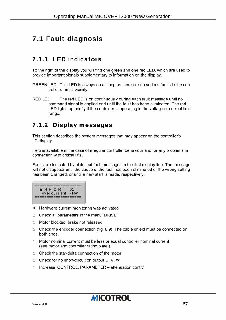
Operating Manual MICOVERT2000 “New Generation”
Version1.8 67
7.1 Fault diagnosis
7.1.1 LED indicators To the right of the display you will find one green and one red LED, which are used to provide important signals supplementary to information on the display. GREEN LED: This LED is always on as long as there are no serious faults in the con-
troller or in its vicinity. RED LED: The red LED is on continuously during each fault message until no
command signal is applied and until the fault has been eliminated. The red LED lights up briefly if the controller is operating in the voltage or current limit range.
7.1.2 Display messages This section describes the system messages that may appear on the controller's LC display. Help is available in the case of irregular controller behaviour and for any problems in connection with critical lifts. Faults are indicated by plain text fault messages in the first display line. The message will not disappear until the cause of the fault has been eliminated or the wrong setting has been changed, or until a new start is made, respectively.
Hardware current monitoring was activated.
Check all parameters in the menu ‘DRIVE’
Motor blocked, brake not released
Check the encoder connection (fig. 8,9). The cable shield must be connected on both ends.
Motor nominal current must be less or equal controller nominal current (see motor and controller rating plate!).
Check the star-delta connection of the motor
Check for no short-circuit on output U, V, W
Increase ‘CONTROL. PARAMETER – attenuation contr.’
==================== E R R O R - 01 overcurrent -HW ====================
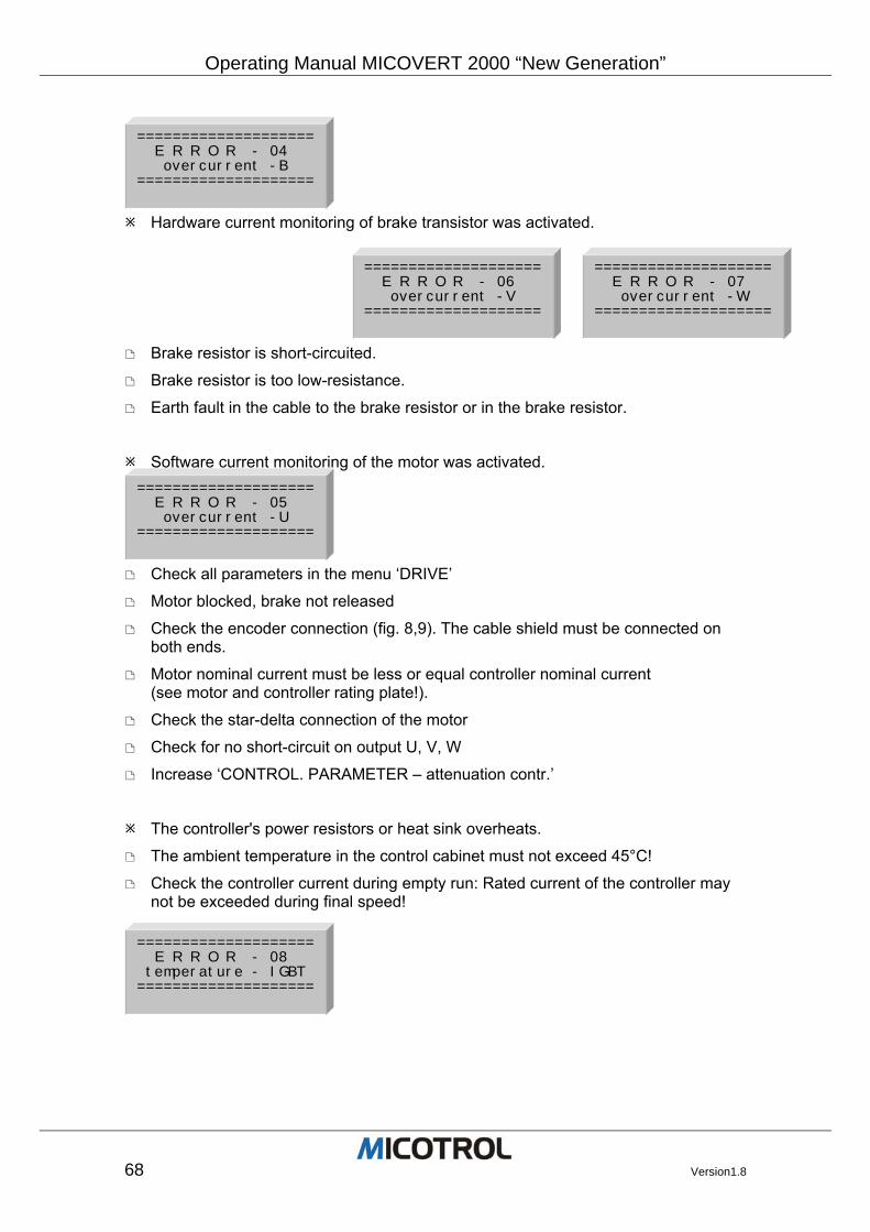
Operating Manual MICOVERT 2000 “New Generation”
68 Version1.8
Hardware current monitoring of brake transistor was activated.
Brake resistor is short-circuited.
Brake resistor is too low-resistance.
Earth fault in the cable to the brake resistor or in the brake resistor.
Software current monitoring of the motor was activated.
Check all parameters in the menu ‘DRIVE’
Motor blocked, brake not released
Check the encoder connection (fig. 8,9). The cable shield must be connected on both ends.
Motor nominal current must be less or equal controller nominal current (see motor and controller rating plate!).
Check the star-delta connection of the motor
Check for no short-circuit on output U, V, W
Increase ‘CONTROL. PARAMETER – attenuation contr.’
The controller's power resistors or heat sink overheats.
The ambient temperature in the control cabinet must not exceed 45°C!
Check the controller current during empty run: Rated current of the controller may not be exceeded during final speed!
==================== E R R O R - 04 overcurrent -B ====================
==================== E R R O R - 05 overcurrent -U ====================
==================== E R R O R - 06 overcurrent -V ====================
==================== E R R O R - 07 overcurrent -W ====================
==================== E R R O R - 08 temperature - IGBT ====================
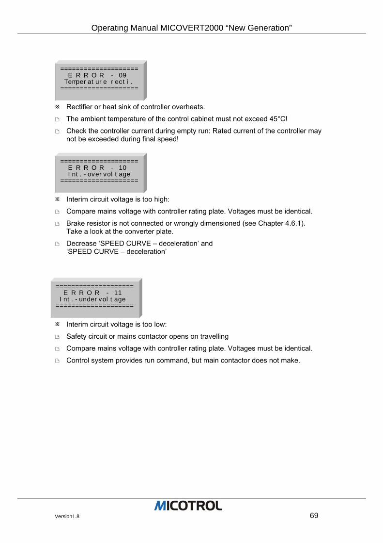
Operating Manual MICOVERT2000 “New Generation”
Version1.8 69
Rectifier or heat sink of controller overheats.
The ambient temperature of the control cabinet must not exceed 45°C!
Check the controller current during empty run: Rated current of the controller may not be exceeded during final speed!
Interim circuit voltage is too high:
Compare mains voltage with controller rating plate. Voltages must be identical.
Brake resistor is not connected or wrongly dimensioned (see Chapter 4.6.1). Take a look at the converter plate.
Decrease ‘SPEED CURVE – deceleration’ and ‘SPEED CURVE – deceleration’
Interim circuit voltage is too low:
Safety circuit or mains contactor opens on travelling
Compare mains voltage with controller rating plate. Voltages must be identical.
Control system provides run command, but main contactor does not make.
==================== E R R O R - 09 Temperature recti. ====================
==================== E R R O R - 10 Int.-overvoltage ====================
==================== E R R O R - 11 Int.-undervoltage ====================
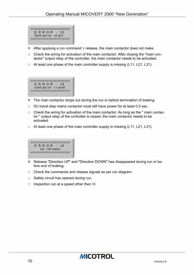
Operating Manual MICOVERT 2000 “New Generation”
70 Version1.8
After applying a run command + release, the main contactor does not make.
Check the wiring for activation of the main contactor: After closing the "main con-tactor" output relay of the controller, the main contactor needs to be activated.
At least one phase of the main controller supply is missing (L11, L21, L31).
The main contactor drops out during the run or before termination of braking.
On travel stop mains contactor must still have power for at least 0.5 sec.
Check the wiring for activation of the main contactor: As long as the " main contac-tor " output relay of the controller is closed, the main contactor needs to be activated.
At least one phase of the main controller supply is missing (L11, L21, L31).
Release "Direction UP" and "Direction DOWN" has disappeared during run or be-fore end of braking.
Check the commands and release signals as per run diagram.
Safety circuit has opened during run.
Inspection run at a speed other then Vi.
==================== E R R O R - 12 Contactor start ====================
==================== E R R O R - 13 contactor travel ====================
==================== E R R O R - 14 no release ====================
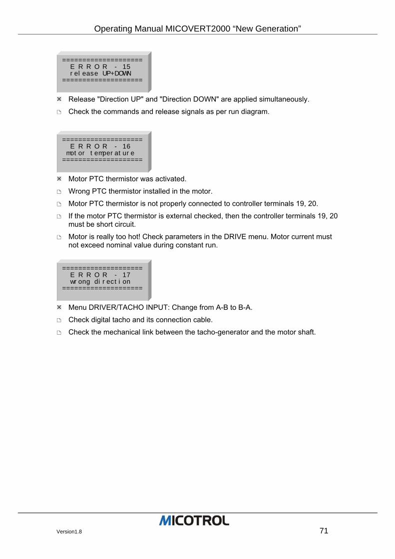
Operating Manual MICOVERT2000 “New Generation”
Version1.8 71
Release "Direction UP" and "Direction DOWN" are applied simultaneously.
Check the commands and release signals as per run diagram.
Motor PTC thermistor was activated.
Wrong PTC thermistor installed in the motor.
Motor PTC thermistor is not properly connected to controller terminals 19, 20.
If the motor PTC thermistor is external checked, then the controller terminals 19, 20 must be short circuit.
Motor is really too hot! Check parameters in the DRIVE menu. Motor current must not exceed nominal value during constant run.
Menu DRIVER/TACHO INPUT: Change from A-B to B-A.
Check digital tacho and its connection cable.
Check the mechanical link between the tacho-generator and the motor shaft.
==================== E R R O R - 15 release UP+DOWN ====================
==================== E R R O R - 16 motor temperature ====================
==================== E R R O R - 17 wrong direction ====================
Operating Manual MICOVERT 2000 “New Generation”
72 Version1.8
Motor speed cannot keep up with the set run curve. Possibility A: Message while starting or during a run
Compare the pulse number setting (DRIVE menu) with the tacho pulses and cor-rect if necessary.
Compare the motor data setting (DRIVE menu) with the motor rating plate and cor-rect if necessary.
Check encoder and encoder coupling!
Motor rating is inadequate.
Mains voltage is too low. Possibility B: Message during deceleration.
Check brake resistor (see Chapter 4.6).
Brake path too short (see Figure 11).
Main menu SPEED CURVE: Reduce JERK DECELERATION / DECELERATION.
Possibility C: Message during stop (during the length of the levelling flag)
Main contactor or mechanical brake is switched off too soon. The mechanical brake must only be applied when lift is at standstill! Main contactor must remain made for approx. 0.5 seconds after standstill.
no pulses from the tacho Possibility A: Motor does not start up.
Mechanical brake is not released.
Line between controller and motor is broken.
Star point missing from motor winding. Possibility B: Motor starts up but is switched off by the controller after a few seconds.
No tacho pulses in at least one tacho input pulse line.
Check tacho-generator!
Check tacho-generator connections!
Check the tacho-generator coupling!
==================== E R R O R - 18 variance ====================
==================== E R R O R - 19 encoder failure ====================
Operating Manual MICOVERT2000 “New Generation”
Version1.8 73
Internal intermediate circuit voltage is too low approx. 5 seconds after mains volt-age is switched on.
Mains voltage is too low.
Controller is designed for higher mains voltage: Compare controller rating plate with mains voltage.
Earth fault on brake resistor or brake resistor line.
Release "Direction UP" and "Direction DOWN" change during run.
Check the commands and release signals as per run diagram.
One or more motor phase has connection to earth.
Check motor and motor wires.
The voltages for the IGBT’s are down.
Contact Micotrol service.
The checksum in the EEPROM is wrong.
Contact Micotrol service.
==================== E R R O R - 20 int. precharge ====================
==================== E R R O R - 21 release direction ====================
==================== E R R O R - 22 earth connection ====================
==================== E R R O R - 23 INTERNAL driver ====================
==================== E R R O R - 24 EEPROM check ====================
Operating Manual MICOVERT 2000 “New Generation”
74 Version1.8
A certain error has three times in follow arisen.
(the attitude which errors are reacted can only in work with MICOTROL be made and must thus when ordering be indicated. If necessary contact service!)
Separate the regulator for 10sec from mains and then restart.
Contact Micotrol service.
! red LED ERROR lights up during travel overload ! Possibility A: during acceleration
SPEED CURVE main menu: Reduce ACCELERATION and JERK ACCELERATION!
Possibility B: during constant run with V4
Mechanical brake not released, drive is blocked. Check mechanical brake.
Check parameters in DRIVE main menu!
Main menu SPEED: reduce V4!
Check parameters in DRIVE main menu! Possibility C: during deceleration
Main menu SPEED CURVE: reduce DECELERATION and JERK DECELERATION!
Check brake resistance! Type? Connections? Capacity?
Command V1 is switched off too soon.
==================== E R R O R - 25 repeated error ====================
Operating Manual MICOVERT2000 “New Generation”
Version1.8 75
7.1.3 Unexpected running characteristics
Drive starts up with a jolt Possibility A: On an empty up run
Motor must not start up against an applied brake! If necessary, extend the starting delay (START/STOP menu).
Possibility B: On an empty down run.
In the case of a 2:1 suspension with rollers on the side of the cabin, make sure that the cabin guide system is working properly otherwise the cabin will be pulled at first on just one side upon start.
The use of guide rolls is advisable for perfect starting at speeds higher than 1.6 m/s.
Cabin/drive vibrates while running in
Increase ATT. DECEL. (CONTROLLER PARAMETERS menu) until you can no longer feel any vibrations in the cabin.
Jolting while stopping. Possibility A: When passing the levelling switch.
Reduce the BRAKING RAMP (SPEED CURVE menu), e.g. from 0.1m/s² to 0.05ms². You must then adjust the stopping accuracy, however, with V1 (SPEED menu).
Possibility B: When at standstill.
Main contactor drops out too soon (see description of FAULT SET/ACTUAL DIFFERENCE, 2nd possibility).
Mechanical brake engages too soon.
UP or DOWN command is switched off too soon. UP or DOWN must be retained for at least 0.5 seconds after standstill is reached.
Operating Manual MICOVERT 2000 “New Generation”
76 Version1.8
7.1.4 Controller faults If changing of the parameters and data entries cannot eliminate controller faults and disturbances there is generally no chance of repairing the controller successfully on site. Customer repairs to the main board are not possible because they require special instrumentation, which is only available in our testing laboratory.
PLEASE NOTE: We draw express attention to the fact that repairs to the main board should only be carried out by our service technicians as there is a risk of destroying expensive digital components. IGBT power semi-conductors are only to be replaced by MICOTROL!
The front panel should not be removed again from the p.c. board once the terminal connections have been made. Underneath the panel are touch-sensitive digital com-ponents that will be destroyed especially if subjected to static charge. There are no control and indicator elements under the metal cover that need to be accessed.
Operating Manual MICOVERT2000 “New Generation”
Version1.8 77
7.2 Replacement of EPROMS
In certain special cases it may be necessary to replace the programmable memory component (EPROM) in consultation with MICOTROL. This might be necessary in special cases of application where use is made of modified software. In these cases, proceed as follows:
Disconnect the controller from mains.
Remove the front panel.
MICOTROL will let you know which EPROM is to be replaced. Carefully pull it up and out of the socket, preferably using the clamp-type tool designed specially for the purpose. First note which way the notch on the top of the component is point-ing!
Insert the replacement IC in the correct direction (notch). Work carefully so that all the legs slide into the socket without buckling.
7.3 Servicing and spare parts
Servicing The MICOVERT series of controllers require no maintenance. The electronic compo-nents used display long-term stability and are subject to no wear. Servicing is confined, therefore, to checking the terminals regularly to ensure that they are done up tight and examining the relay contacts on the output relays for signs of arc erosion. To prevent leakage current and flashover you should remove any dust which may col-lect on the chips and heat sinks. Pay special attention to the heat sink fins and the external fans where present.
Replacement parts No repairs may be carried out to the main board on-site and none of its components may be replaced without risk of destroying the sensitive digital components. All work on the main board should be carried out at the factory in Alzenau, Germany. Replacement parts for defective components should be obtained only from MICOTROL. We guaran-tee that the components are suitable for the purposes and have been tested.
PLEASE NOTE: Power semi-conductors may only be replaced by MICOTROL!
Operating Manual MICOVERT 2000 “New Generation”
78 Version1.8
8 Product liability and warranty
We guarantee the faultless condition of our product as described in our advertising, the product documentation we have published, and this operating manual. Product charac-teristics over and above this are not guaranteed. In particular we give no guar-antee nor do we accept any legal responsibility or liability of any kind for the MICOVERT 2000 controller, for its effi-ciency or faultless operation for any other purpose than that defined in Chapter 2.1. Claims for damages are generally ex-cluded, except in the case of proven premeditation, gross negligence by MICOTROL, or the absence of any prom-ised features. In particular we do not accept any liability if the controllers are used with lift control systems, encoders, power supply systems and drive motors for which the controllers are unsuitable as stated in this operating manual or which fail to conform with the customary state of technology by virtue of their individual design. We also disclaim responsibility for any damage to lift facilities and building facilities due to malfunction of the product or due to errors in the operating manual. We are not responsible for violation of the patents and other rights of third parties. We shall not be liable for any damage re-sulting from improper handling as defined in this operating manual. We expressly ex-clude liability for lost profit and especially for consequential damage due to the non-observance of safety regulations and warn-ings and/or resulting from accessories not supplied by MICOTROL. MICOTROL products may not be sold in the United States of America and other countries governed by U.S. American law.
MICOTROL products are designed for a long service life. They conform with the cur-rent state of science and technology and were individually tested in all their promised functions prior to shipment. MICOTROL is continuously engaged in product and mar-ket analysis in the interest of further development and constant improvement. However, if any malfunctions or break-downs occur in spite of all the preventive measures, you should notify the customer service department in Alzenau, Germany. We assure you that suitable action to rectify the damage will be taken without delay.
Terms of warranty We guarantee the product's proper working order as defined in this operating manual for a period of 24 months after shipment as per delivery note. Repairs will only be carried out free of charge if the operating manual was observed for storage, transportation, instal-lation, commissioning and operation. Interventions in a unit by the customer or third parties are only allowed after special consultation with MICOTROL. If this condi-tion is not observed, MICOTROL will accept no responsibility for any damage to the unit, injury to persons or consequential damage; in this case the warranty shall expire. MICOTROL also disclaims all responsibility for unit faults resulting from damaged or functionally defective equipment in the con-troller's environment or following the use of accessories which were not supplied by MICOTROL. The General Terms of Business of MICOTROL International GmbH shall ap-ply.