Embed Size (px)
Citation preview
ThyssenKrupp Aufzugswerke A company
of ThyssenKruppElevator
Operating Manual
Speed governor GBTK 6023F

OPERATING INSTRUCTIONS
ThyssenKrupp Aufzugswerke GmbH
Imprint
All rights reserved © Copyright by: THYSSENKRUPP AUFZUGSWERKE GmbH
Postfach 23 03 70, D-70623 Stuttgart Printed in Germany These operating instructions may – even in extract form – only be reprinted or otherwise copied with the express written approval of THYSSENKRUPP AUFZUGSWERKE GmbH. All copying, distribution or saving in any form on data storage media which is not authorised by THYSSENKRUPP AUFZUGSWERKE GmbH constitutes a copyright infringement and will result in prosecution. We expressly reserve the right to carry out technical alterations which lead to an improvement of our products or increase the safety standard – also without special prior notice. The issuer responsible for the content: THYSSENKRUPP AUFZUGSWERKE GmbH
Preface
We are delighted that you have decided upon a quality product from the company THYSSENKRUPP AUFZUGSWERKE GmbH. These operating instructions will help you to get to know our products and to benefit from their intended applications. Important safety and hazard instructions will help you to operate our products safely and properly. Subject to technical alterations.


OPERATING MANUAL
ThyssenKrupp Aufzugswerke GmbH
Table of contents:
Speed governor PAGE
1. General information 1.1 Explanation of the symbols used 6 1.2 Safety instructions 7 1.3 Speed governor 10 1.4 Functional description 11
2. Product description 2.1 Structure 12 2.2 Configuration table 13 2.3 Types 14 2.3.1 Basic type 15 2.3.2 Blocking device, rocker blockable
with voltage - remote tripping 16 2.3.3 Blocking device, rocker blockable without voltage 17 2.4 Governor pulley 18 2.5 Switch mounting - electrical monitoring 19 2.6 Mounting 20 2.7 Sensors (initiator attachment) 21 2.8 Reinforcement plate (safety gear operation upwards) 22 2.9 Rope dislocation protection 22 2.10 Electrical connection - wiring diagrams 23
3. Rope data and tensioning devices 3.1 Rope data 24
4. Techn. data 4.1 General 25 4.2 Dimensions, installation position, weights 26 4.3 Type plate 30
5. Installation 31
6. Commissioning 32
7. Inspection and cleaning 33
8. Transport and storage 34
Appendix Type test certificate Declaration of conformity
5

OPERATING MANUAL 1. SAFETY
ThyssenKrupp Aufzugswerke GmbH
1.1 Explanation of the symbols used
The following pictograms and designations are used in this operating manual:
Danger This symbol indicates extreme danger to life and the health of persons. Nonobservance can lead to death or severe injury!
Danger This symbol indicates an immediate danger to the life and health of persons due to electrical current. Hazard warnings must always be observed!
Warning This symbol warns against imminent danger. Nonobservance can lead to bodily injury or extensive damage to property. Warnings must always be observed!
Note This symbol indicates important information and operating instructions. Nonobservance can lead to damage, danger or malfunctions.
Check Test steps are specified with this symbol. The test instructions marked in this way are to be followed without fail. They contribute to preventing personal injury or damage to property.
6

OPERATING MANUAL 1. SAFETY
ThyssenKrupp Aufzugswerke GmbH
1.2 Safety instructions
Notes regarding the operating manual A requirement for safe handling and non-disruptive operation this assembly is knowledge of the fundamental safety regulations. This operating manual contains the most important information that is required to operate the assembly safely. The operating manual, in particular the safety instructions, is to be complied with by all persons that work on this assembly. Furthermore, the rules and regulations covering accident prevention that apply to the usage site are to be complied with.
Obligations of the operator The operator undertakes only to allow persons to work on the assembly who • are familiar with the regulations regarding work safety and accident
prevention and have been instructed in handling the assembly. • have read the chapter on safety and the warnings in this operating
manual. Note: Check at regular intervals that the personnel work with a heightened awareness with regard to safety.
Obligation of the personnel Persons assigned to work on the assembly undertake before starting work to • observe the regulations regarding work safety and accident prevention. • read the chapter on safety and the warnings in this operating manual.
Training of the personnel Only trained and instructed qualified personnel may work on the assembly. The responsibility of the personnel is to be clearly defined for all tasks involving commissioning, operation, maintenance and repair.
Organisational measures The required personal protective equipment is to be provided by the operator. All existing safety device are to be checked regularly in accordance with the maintenance plan.
7

OPERATING MANUAL 1. SAFETY
ThyssenKrupp Aufzugswerke GmbH
Informal notes on the safety measures • The operating manual is to be kept permanently at the usage site of the
installation. • Complementary to the operating manual, the generally applicable and
local regulations for accident prevention and environmental protection are to be provided and complied with.
• Legally prescribed safety instructions are to be provided for the users at clearly visible positions.
• Keep all safety and hazard warnings on the installation in a legible condition.
Use in line with intended purpose The speed governor has been constructed using state-of-the-art technology and in line with the recognised technical safety regulations. The speed governor may only be • deployed in line with the intended purpose and • used when all the technical safety features are in perfect condition. The exclusive intended purpose of the speed governor is deployment as a safety device in accordance with EN 81- 2000. Any other or additional form of use shall be regarded as non-compliant with the intended use. THYSSENKRUPP AUFZUGSWERKE GmbH shall not be liable for any damage arising from such use and any damage arising due to operator errors. Proper use in line with the intended purpose also includes • Observance of all instructions in the operating manual and • Adherence to the commissioning instructions, the installation description
as well as the inspection and maintenance work.
Warranty and liability As a general principle, the 'General Terms of Sale and Delivery' of THYSSENKRUPP AUFZUGSWERKE GmbH apply. Warranty and liability claims in the event of personal injury and damage to property shall be excluded if they arise due to any of the following causes: • Improper use that is not in line with the intended purpose of the speed
governor • Installation, commissioning, operation and maintenance of this product
that is not in line with accepted technical principles of the speed governor • Operation of the speed governor with defective and/or non-operative
safety and protective devices • Nonobservance of the instructions in the operating manual with regard to
Transport, storage, installation, commissioning, operation and maintenance of the speed governor
• Constructional changes to the speed governor performed by persons other than Thyssen Aufzugswerke employees
• Deficient monitoring of parts that are subject to wear
8
OPERATING MANUAL 1. SAFETY
ThyssenKrupp Aufzugswerke GmbH
• Repairs that are carried out improperly • Case of catastrophe due to third-party interference or force majeure.
Constructional changes to the speed governor The speed governor is a safety device with type test certificate. It has been set at the plant to the specified tripping speed and lead-sealed. The setting with added safety switches is secured by paint sealing. No changes may be made to these settings.
9
OPERATING MANUAL 1. FUNCTIONAL DESCRIPTION
ThyssenKrupp Aufzugswerke GmbH
1.3 Speed governor
Speed governors are safety devices with type test certificate and type approval marking that, when applied, protect the elevator against non-permitted high or uncontrolled speeds in the transport direction. There are a variety of products adapted to the use cases, and these include a number of options that can be selected. The speed governors (abbreviated to GBTK) are fitted, adjusted and tested individually in the plant, and secured against inadvertent adjustment. After delivery, all the technician needs to do is to mount the speed governor, establish the electrical connection and apply the governor rope.
Notes: Braking devices for the car and counterweight must each be assigned to their own speed governor.
The speed governor may only be operated in conjunction with a rope braking switch that switches off the drive if the rope tension is insufficient or in the event of a rope break.
10
OPERATING MANUAL 1. FUNCTIONAL DESCRIPTION
ThyssenKrupp Aufzugswerke GmbH
1.4 Functional description Tripping: The speed governor works according to the pendulum principle with a cam curve and pulley-guided rocker. It is fitted either in the machine room or in the shaft head. In exceptional cases, it can also be fitted in the shaft pit. The fundamental function principle is the same for all equipment versions. At the set tripping speed, the rocker is deflected via the cam curve in such a way that the pawl of the rocker engages in one of the lugs of the governor pulley and blocks the pulley. The necessary force and the corresponding rope traction for engaging the safety gear are applied to the governor rope via the driving groove. The actuating force for the brake or brake safety gear is generated by a surrounding wire rope, a tensioning weight arranged in the shaft pit and the rope traction of the driving groove that this creates. The speed governor and the related engagement of the safety gear and/or braking device can be tripped in both directions of rotation. The tensile force generated in the governor rope triggered by the speed governor must correspond to at least the higher of the following two values:
Twice the required force for engaging the safety gear at least 300 N
NB! The installation may only be put back into operation after removal of the cause of the malfunction by qualified personnel check of the installation.
11
OPERATING MANUAL 2. PRODUCT DESCRIPTION
ThyssenKrupp Aufzugswerke GmbH
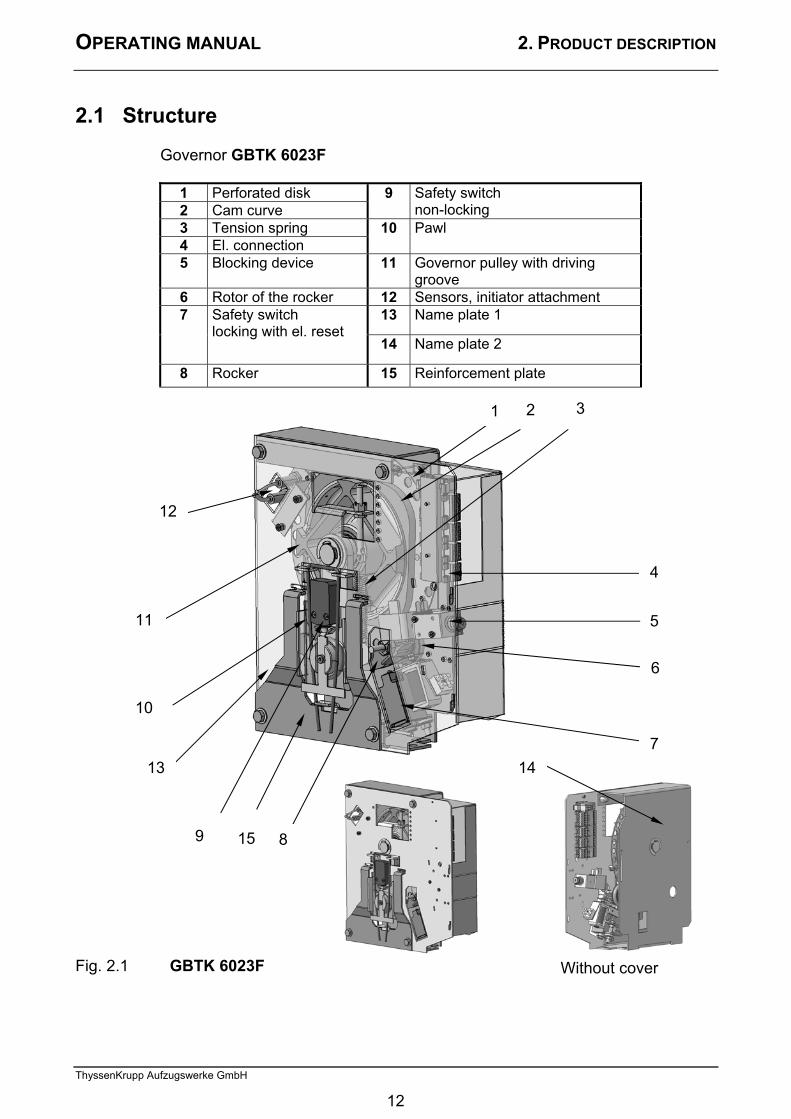
2.1 Structure Governor GBTK 6023F
1 Perforated disk 2 Cam curve
9 Safety switch non-locking
3 Tension spring 4 El. connection
10 Pawl
5 Blocking device 11 Governor pulley with driving groove
6 Rotor of the rocker 12 Sensors, initiator attachment 13 Name plate 1 7 Safety switch
locking with el. reset 14 Name plate 2
8 Rocker 15 Reinforcement plate Fig. 2.1 GBTK 6023F
12
10
9 8
5
7
11
21 3
4
6
13 14
Without cover
15
12
OPERATING MANUAL 2. PRODUCT DESCRIPTION
ThyssenKrupp Aufzugswerke GmbH
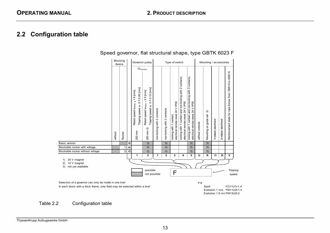
2.2 Configuration table
Table 2.2 Configuration table
200
mm
300
mm
3)
Basic version G 3) 3) 3) 3)Blockable rocker with voltage 1) m 3) 3) 3) 3)Blockable rocker without voltage 2) O 3) 3) 3) 3)
1 2 1 2 3 4 5 U K 1I 2I V1) 24 V magnet2) 12 V magnet3) not yet available
possiblenot possible
Selection of a governor can only be made in one line! e.g.In each block with a thick frame, only field may be selected within a line! Spirit FO11U1I-1.4
Evolution 1 m/s FM11U2I-1.4Evolution 1.6 m/sFM13U2I-2
speedF
Governor pulley
DTraction
Tripping
lock
ing
with
1 c
onta
ct a
nd n
on-lo
ckin
g w
ith 3
con
tact
s,
elec
trica
l rem
ote
rese
t 24
V IP
00
Type of switch Mounting / accessories
Rei
nfor
cem
ent p
late
for r
ope
forc
es fr
om 1
800
N to
400
0 N
1x in
itiato
r atta
chm
ent
non-
lock
ing
with
2 c
onta
cts
Speed governor, flat structural shape, type GBTK 6023 F
Mou
ntin
g on
gui
de ra
il 3
)
Roc
ker
with
out
Blocking device
non-
lock
ing
with
3 c
onta
cts
Rat
ed s
peed
vR
ated
≤ 1
.6 [m
/s]
Trip
ping
spe
ed v
A 0
.7-2
.09
[m/s
]
Rat
ed s
peed
vR
ated
≤ 2
.5 [m
/s]
Trip
ping
spe
ed v
A 0
.7-3
.12
[m/s
]
2x in
itiato
r atta
chm
ent
with
out c
onso
le
lock
ing
with
1 c
onta
ct,
elec
trica
l rem
ote
rese
t 24
V IP
00
lock
ing
with
1 c
onta
ct a
nd n
on-lo
ckin
g w
ith 2
con
tact
s,
elec
trica
l rem
ote
rese
t 24
V IP
00
13
OPERATING MANUAL 2. PRODUCT DESCRIPTION
ThyssenKrupp Aufzugswerke GmbH
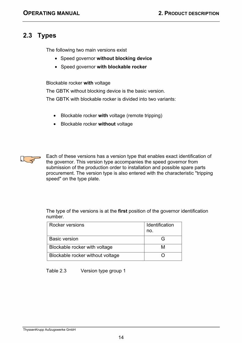
2.3 Types The following two main versions exist
• Speed governor without blocking device
• Speed governor with blockable rocker Blockable rocker with voltage The GBTK without blocking device is the basic version. The GBTK with blockable rocker is divided into two variants:
• Blockable rocker with voltage (remote tripping)
• Blockable rocker without voltage Each of these versions has a version type that enables exact identification of the governor. This version type accompanies the speed governor from submission of the production order to installation and possible spare parts procurement. The version type is also entered with the characteristic "tripping speed" on the type plate. The type of the versions is at the first position of the governor identification number.
Rocker versions Identification no.
Basic version G
Blockable rocker with voltage M
Blockable rocker without voltage O
Table 2.3 Version type group 1
14
OPERATING MANUAL 2. PRODUCT DESCRIPTION
ThyssenKrupp Aufzugswerke GmbH
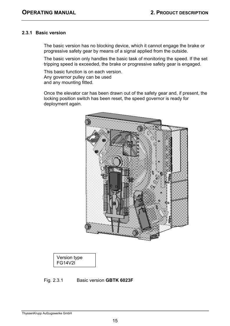
2.3.1 Basic version The basic version has no blocking device, which it cannot engage the brake or progressive safety gear by means of a signal applied from the outside. The basic version only handles the basic task of monitoring the speed. If the set tripping speed is exceeded, the brake or progressive safety gear is engaged. This basic function is on each version. Any governor pulley can be used and any mounting fitted. Once the elevator car has been drawn out of the safety gear and, if present, the locking position switch has been reset, the speed governor is ready for deployment again. Fig. 2.3.1 Basic version GBTK 6023F
Version type FG14V2I
15
OPERATING MANUAL 2. PRODUCT DESCRIPTION
ThyssenKrupp Aufzugswerke GmbH
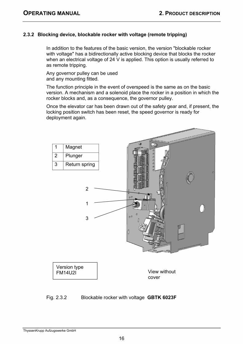
2.3.2 Blocking device, blockable rocker with voltage (remote tripping)
In addition to the features of the basic version, the version "blockable rocker with voltage" has a bidirectionally active blocking device that blocks the rocker when an electrical voltage of 24 V is applied. This option is usually referred to as remote tripping. Any governor pulley can be used and any mounting fitted. The function principle in the event of overspeed is the same as on the basic version. A mechanism and a solenoid place the rocker in a position in which the rocker blocks and, as a consequence, the governor pulley. Once the elevator car has been drawn out of the safety gear and, if present, the locking position switch has been reset, the speed governor is ready for deployment again.
Fig. 2.3.2 Blockable rocker with voltage GBTK 6023F
1 Magnet
2 Plunger
3 Return spring
Version type FM14U2I View without
cover
2
1
3
16
OPERATING MANUAL 2. PRODUCT DESCRIPTION
ThyssenKrupp Aufzugswerke GmbH
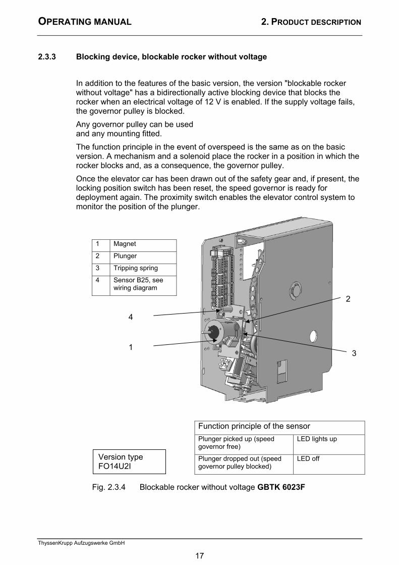
2.3.3 Blocking device, blockable rocker without voltage In addition to the features of the basic version, the version "blockable rocker without voltage" has a bidirectionally active blocking device that blocks the rocker when an electrical voltage of 12 V is enabled. If the supply voltage fails, the governor pulley is blocked. Any governor pulley can be used and any mounting fitted. The function principle in the event of overspeed is the same as on the basic version. A mechanism and a solenoid place the rocker in a position in which the rocker blocks and, as a consequence, the governor pulley. Once the elevator car has been drawn out of the safety gear and, if present, the locking position switch has been reset, the speed governor is ready for deployment again. The proximity switch enables the elevator control system to monitor the position of the plunger.
1 Magnet
2 Plunger
3 Tripping spring
4 Sensor B25, see wiring diagram
Function principle of the sensor Plunger picked up (speed governor free)
LED lights up
Plunger dropped out (speed governor pulley blocked)
LED off
Fig. 2.3.4 Blockable rocker without voltage GBTK 6023F
Version type FO14U2I
1
2
3
4
17

OPERATING MANUAL 2. PRODUCT DESCRIPTION
ThyssenKrupp Aufzugswerke GmbH
2.4 Governor pulleys
As standard, the driving groove diameter is 200 mm and the driving groove is hardened. Groove form: vee groove Vee groove angle: 40° Each governor pulley has a perforated disk. See 2.7
The type of the versions is at the second position of the governor identification number.
Governor pulley type: Identification no.
Driving groove diameter 200 mm 1
Driving groove diameter 300 mm 2
Table 2.4. Version type group 2
18

OPERATING MANUAL 2. PRODUCT DESCRIPTION
ThyssenKrupp Aufzugswerke GmbH
2.5 Switch mounting – Electrical monitoring in accordance with EN 81-1:2000
The state and possibly also state changes must be queried electrically. EN 81-1:2000 prescribes an electrical pre-switching as of rated speeds of > 1.0 m/s. This switch must be locking. The locking switch must be reset after tripping to recommission the installation. This takes place via an electrical remote reset of the locking switch.
Switch mounting GBTK 6023F The type of the versions is at the third position of the governor identification number. Table 2.5 Version type group 3 The speed governor must lead to shutdown of the elevator by means of an electric safety device in accordance with EN 81-1:2000 14.1.2.
1 Non-locking safety switch
2 Locking safety switch with remote reset
3 Electrical blocking device (remote tripping)
4 Reset
Safety switch versions in accordance with EN 81-1:2000, 9.9.11, 14.1.2.2
Identification no.
Vrated ≤ 1.0 m/s
Vrated > 1.0 m/s
non-locking with 2 contacts 1 — non-locking with 3 contacts 2 —
locking with 1 contact, electrical remote reset 24 V IP00 3 locking with 1 contact and non-locking with 2 contacts, electrical remote reset 24 V IP00 4
locking with 1 contact and non-locking with 3 contacts, electrical remote reset 24 V IP00
5
Version type FM14U21
3
4
2
1
19

OPERATING MANUAL 2. PRODUCT DESCRIPTION
ThyssenKrupp Aufzugswerke GmbH
2.6 Mounting The speed governor is mounted on the guide rail or with a console on the machine base frame. If a final limit switch OFF is fitted, an additional mounting is fitted on this console to open the safety circuit when the elevator car moved beyond the end position. The type of the versions is at the fourth position of the governor identification number.
Mounting version Identification no.
bottom, without console U
Mounting on guide rail Q
Table 2.6 Version type group 4
20

OPERATING MANUAL 2. PRODUCT DESCRIPTION
ThyssenKrupp Aufzugswerke GmbH
2.7 Sensors (initiator attachment) Application examples: 1. Detecting the movements of the elevator car in the event of
emergency evacuation. One sensor is adequate.
2. Detecting the movements of the elevator car in the event of a change in the direction of travel. Two sensors are required.
See Fig. 2.1 Item 1 perforated disk 36 holes Item 12 Inductive proximity switch NPN circuit 10-30 VDC Output Imax=200 mA
21
OPERATING MANUAL 2. PRODUCT DESCRIPTION
ThyssenKrupp Aufzugswerke GmbH
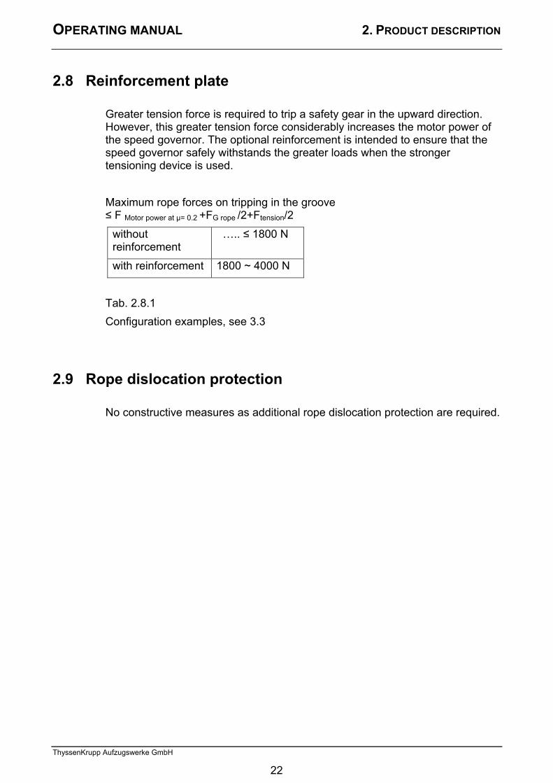
2.8 Reinforcement plate Greater tension force is required to trip a safety gear in the upward direction. However, this greater tension force considerably increases the motor power of the speed governor. The optional reinforcement is intended to ensure that the speed governor safely withstands the greater loads when the stronger tensioning device is used. Maximum rope forces on tripping in the groove ≤ F Motor power at µ= 0.2 +FG rope /2+Ftension/2
without reinforcement
….. ≤ 1800 N
with reinforcement 1800 ~ 4000 N
Tab. 2.8.1 Configuration examples, see 3.3
2.9 Rope dislocation protection No constructive measures as additional rope dislocation protection are required.
22
OPERATING MANUAL 2. PRODUCT DESCRIPTION
ThyssenKrupp Aufzugswerke GmbH
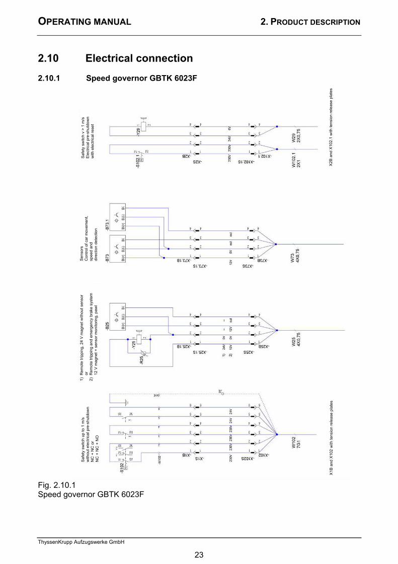
2.10 Electrical connection 2.10.1 Speed governor GBTK 6023F Fig. 2.10.1 Speed governor GBTK 6023F
Saf
ety
switc
h v
> 1
m/s
E
lect
rical
pre
-shu
tdow
n w
ith e
lect
rical
rese
t
Saf
ety
switc
h up
to 1
m/s
w
ithou
t ele
ctric
al p
re-s
hutd
own
NC
+ N
C o
r N
C +
NC
+ N
O
1) R
emot
e tri
ppin
g, 2
4 V
mag
net w
ithou
t sen
sor
or
2)
Rem
ote
tripp
ing
and
emer
genc
y br
ake
syst
em
12
V m
agne
t + s
enso
r mon
itorin
g, p
awl
Sen
sors
C
ontro
l of c
ar m
ovem
ent,
sp
eed
and
di
rect
ion
dete
ctio
n
X2B
and
X10
2.1
with
tens
ion
rele
ase
plat
es
X1B
and
X10
2 w
ith te
nsio
n re
leas
e pl
ates
23

OPERATING MANUAL 3. TENSIONING DEVICES AND ROPES
ThyssenKrupp Aufzugswerke GmbH
3. Rope data and tensioning devices 3.1 Rope data
Recommendation:
Table 3.1.1 Rope data
Note: the minimum breaking load of the rope must be at least 8 times the tensile force that can be generated by the tripped speed governor in the cable, whereby a coefficient of friction of µmax = 0.2 is to be taken into account (EN81.9.9.6.2).
Nominal diameter (mm) 6,5 Type 6x19 Warrington with fibre core Weight per meter (kg/m) 0,154 Breaking load (kN) 30,1 Minimum breaking load (kN) 26,5
24
OPERATING MANUAL 4. TECHNOLOGY
ThyssenKrupp Aufzugswerke GmbH
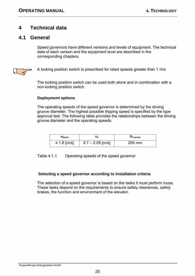
4 Technical data 4.1 General
Speed governors have different versions and levels of equipment. The technical data of each version and the equipment level are described in the corresponding chapters. A locking position switch is prescribed for rated speeds greater than 1 m/s The locking position switch can be used both alone and in combination with a non-locking position switch. Deployment options
The operating speeds of the speed governor is determined by the driving groove diameter. The highest possible tripping speed is specified by the type approval test. The following table provides the relationships between the driving groove diameter and the operating speeds.
vRated vA DTraction ≤ 1.6 [m/s] 0.7 – 2.09 [m/s] 200 mm
Table 4.1.1 Operating speeds of the speed governor
Selecting a speed governor according to installation criteria
The selection of a speed governor is based on the tasks it must perform muss. These tasks depend on the requirements to ensure safety clearances, safety brakes, the function and environment of the elevator.
25
OPERATING MANUAL 4. TECHNOLOGY
ThyssenKrupp Aufzugswerke GmbH
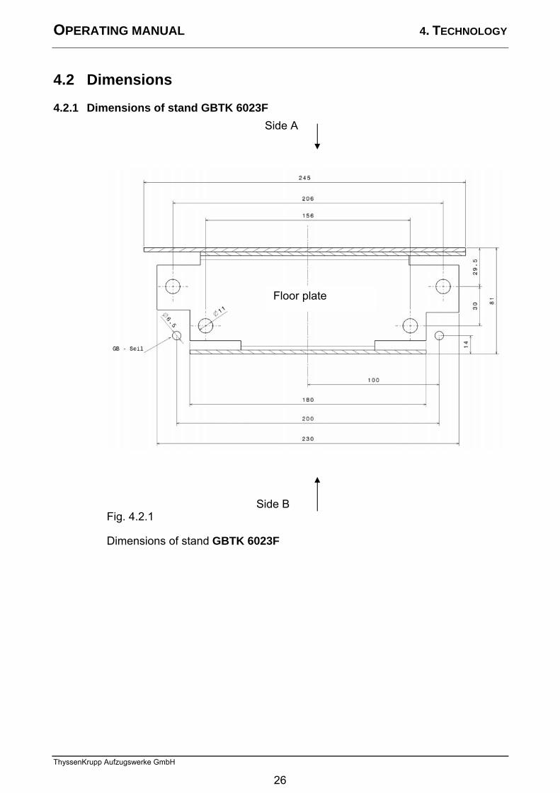
4.2 Dimensions 4.2.1 Dimensions of stand GBTK 6023F
Fig. 4.2.1
Dimensions of stand GBTK 6023F
Side A
Side B
Floor plate
26
OPERATING MANUAL 4. TECHNOLOGY
ThyssenKrupp Aufzugswerke GmbH
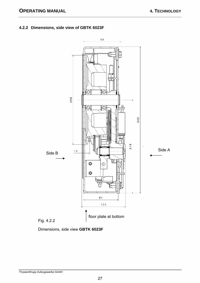
4.2.2 Dimensions, side view of GBTK 6023F
Fig. 4.2.2
Dimensions, side view GBTK 6023F
Side A Side B
floor plate at bottom
27
OPERATING MANUAL 4. TECHNOLOGY
ThyssenKrupp Aufzugswerke GmbH
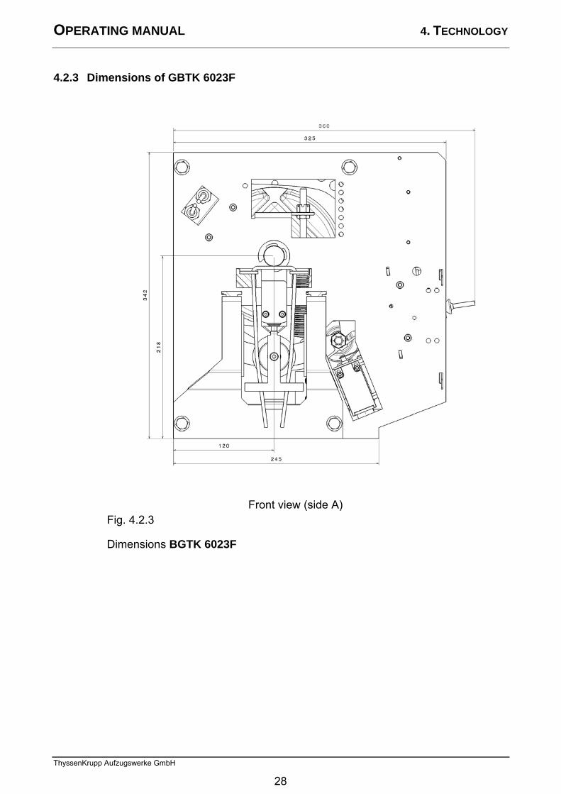
4.2.3 Dimensions of GBTK 6023F
Fig. 4.2.3
Dimensions BGTK 6023F
Front view (side A)
28
OPERATING MANUAL 4. TECHNOLOGY
ThyssenKrupp Aufzugswerke GmbH
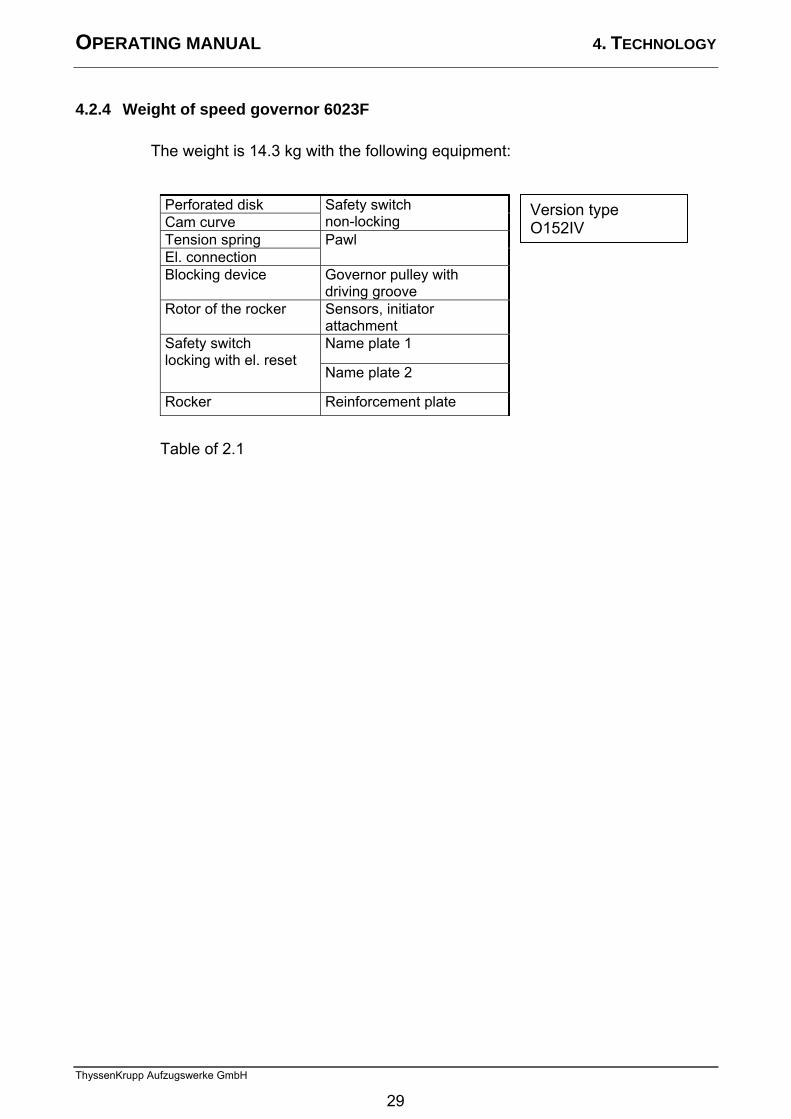
4.2.4 Weight of speed governor 6023F
The weight is 14.3 kg with the following equipment:
Perforated disk Cam curve
Safety switch non-locking
Tension spring El. connection
Pawl
Blocking device Governor pulley with driving groove
Rotor of the rocker Sensors, initiator attachment Name plate 1 Safety switch
locking with el. reset Name plate 2
Rocker Reinforcement plate
Table of 2.1
Version type O152IV
29
OPERATING MANUAL 4. TECHNOLOGY
ThyssenKrupp Aufzugswerke GmbH
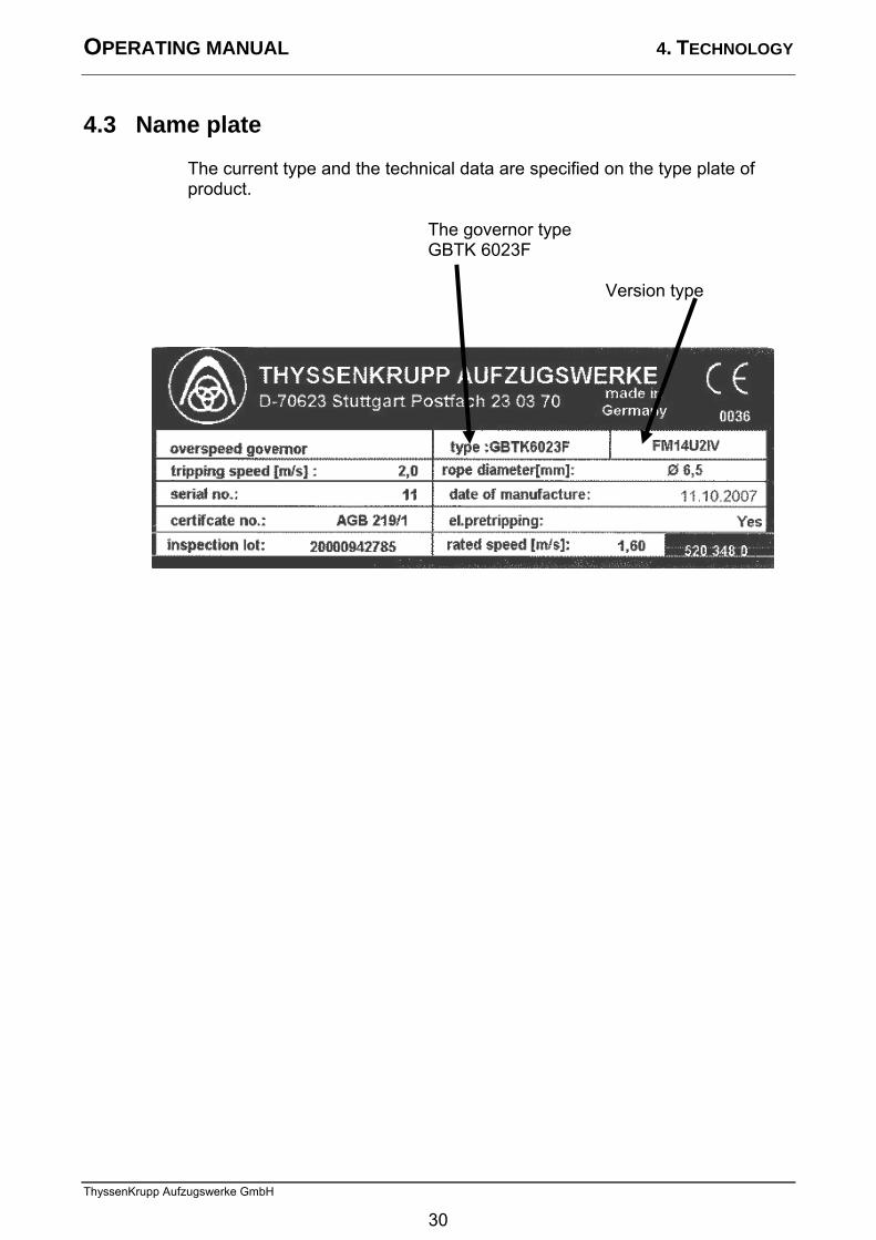
4.3 Name plate
The current type and the technical data are specified on the type plate of product.
The governor type GBTK 6023F
Version type
30
OPERATING MANUAL 5. INSTALLATION
ThyssenKrupp Aufzugswerke GmbH
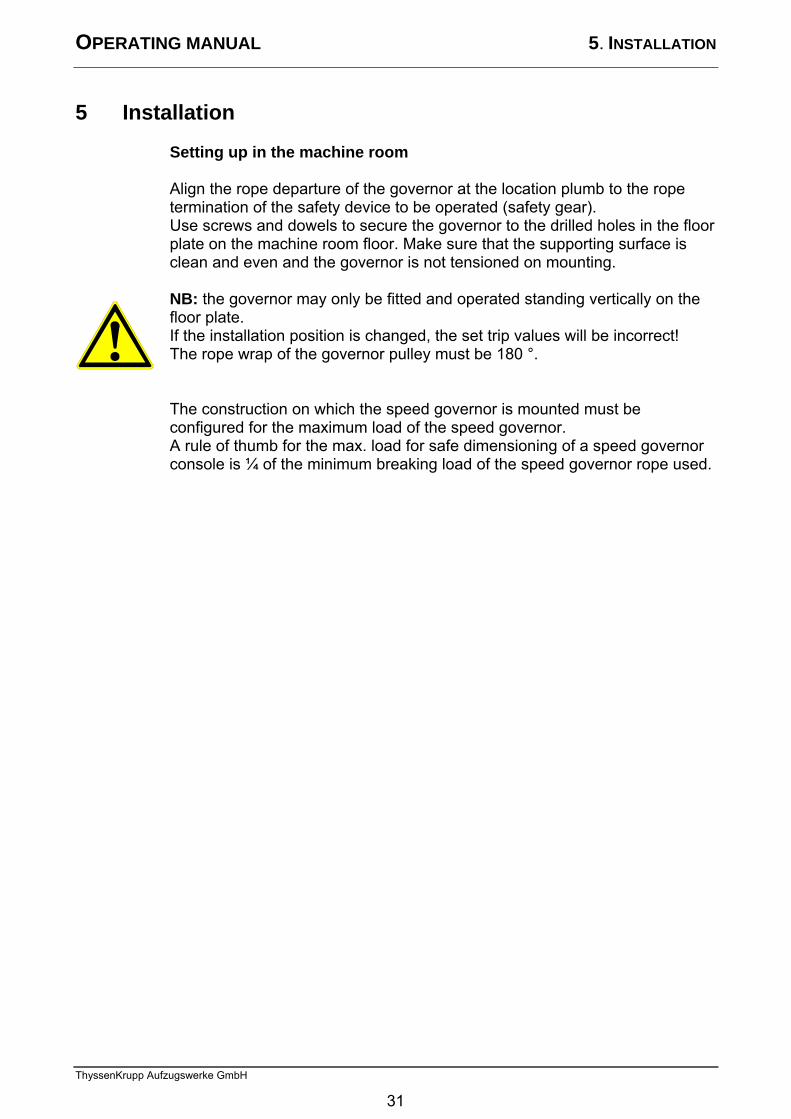
5 Installation Setting up in the machine room
Align the rope departure of the governor at the location plumb to the rope termination of the safety device to be operated (safety gear). Use screws and dowels to secure the governor to the drilled holes in the floor plate on the machine room floor. Make sure that the supporting surface is clean and even and the governor is not tensioned on mounting. NB: the governor may only be fitted and operated standing vertically on the floor plate. If the installation position is changed, the set trip values will be incorrect! The rope wrap of the governor pulley must be 180 °. The construction on which the speed governor is mounted must be configured for the maximum load of the speed governor. A rule of thumb for the max. load for safe dimensioning of a speed governor console is ¼ of the minimum breaking load of the speed governor rope used.
31

OPERATING MANUAL 6/7/8 COMMISSIONING / MAINTENANCE TRANSPORT
ThyssenKrupp Aufzugswerke GmbH
6 Commissioning and settings
Before commissioning the installation, check the function of the governor. In the same way, the function and effect of add-on special versions, if present, are to be checked.
32

OPERATING MANUAL 6/7/8 COMMISSIONING / MAINTENANCE TRANSPORT
ThyssenKrupp Aufzugswerke GmbH
7 Inspection and cleaning The speed governor is a type-approved safety device and is maintenance
free. It has been set at the plant to the specified tripping speed and lead-sealed. The setting with added safety switches (optional) is secured by paint sealing. No changes may be made to these settings.
Inspection interval The inspection is to be carried out together with overall maintenance of the elevator system. However, at least once a year. Note: commissioning and repair work may only be carried out by trained and instructed qualified personnel. All laws and regulation for elevator systems as well as accident prevention regulations must be known and complied with. During inspection of the governor, the following checks are to be carried out:
Rotor of the rocker Governor pulley Ease of movement
General visual check Running noise
Rubber coating free of cracks
The groove must not be worn
no damage If repair or adjustment work is necessary on the governor, this is to be done in the plant, or the governor is to be replaced. No not dismantle the speed governor. There are no parts that you can replace. Note: The bearings of the governor pulley of the rocker, as well as the roller and cam curve, are maintenance free and do not have to be oiled or greased. Cleaning The surface as well as all accessible parts must not be cleaned using scratching or scouring cleaning agents. Use e.g. THYSSENKRUPP AUFZUGSWERKE GmbH R1 cleaner.
Blocking devices (remote tripping … etc. ) Check ease of movement of the magnet Check that the magnet drops out
33
OPERATING MANUAL 6/7/8 COMMISSIONING / MAINTENANCE TRANSPORT
ThyssenKrupp Aufzugswerke GmbH
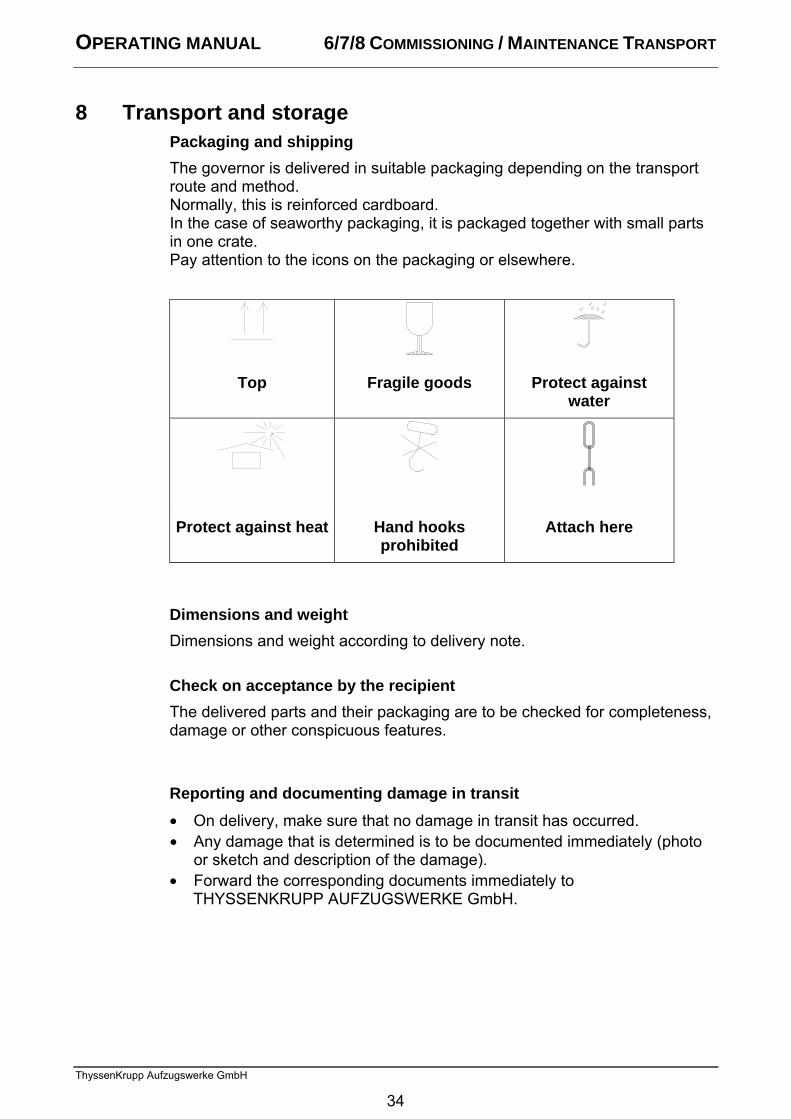
8 Transport and storage Packaging and shipping
The governor is delivered in suitable packaging depending on the transport route and method. Normally, this is reinforced cardboard. In the case of seaworthy packaging, it is packaged together with small parts in one crate. Pay attention to the icons on the packaging or elsewhere.
Top Fragile goods Protect against water
Protect against heat Hand hooks prohibited
Attach here
Dimensions and weight Dimensions and weight according to delivery note. Check on acceptance by the recipient The delivered parts and their packaging are to be checked for completeness, damage or other conspicuous features. Reporting and documenting damage in transit • On delivery, make sure that no damage in transit has occurred. • Any damage that is determined is to be documented immediately (photo
or sketch and description of the damage). • Forward the corresponding documents immediately to
THYSSENKRUPP AUFZUGSWERKE GmbH.
34
OPERATING MANUAL 6/7/8 COMMISSIONING / MAINTENANCE TRANSPORT
ThyssenKrupp Aufzugswerke GmbH
Unpacking
• Dispose of packaging materials in an environmentally compatible manner or reuse them.
• Specific transport aids and shipping braces remain with the customer. Intermediate storage
• If the governor is not mounted immediate after delivery, protect it against moisture, humidity and damage.
Ambient conditions
Note: The regulations for elevator machine and pulley rooms apply with regard to the ambient conditions at the final location (humidity, temperature). The room temperature should be in the range from +5 to +40 °C.
35


ThyssenKrupp Aufzugswerke GmbH Ein Unternehmen von ThyssenKrupp Elevator Bernhäuser Strasse 45 73765 Neuhausen a. d. F. Deutschland Tel.: +49 7158/12-0 Fax: +49 7158/12-2585 E-Mail: [email protected] www.thyssenkrupp-aufzuege.de Is
sue
10/
2007
Nr.
971
0 00
0 92
62

![HSBC iy/g;];ily; fld; tpz;zg;gg; gbtk; Banking... · HSBC iy/g;];ily; fld; tpz;zg;gg; gbtk; mYtyfg; ghtidf;F kl;Lk; - LSL001706 (T) fpis$DSS FwpaPL mYtyhpd; ngah; ... cyfshtpa Nrit](https://img.pdfslide.net/doc/110x75/5a700e9c7f8b9aac538b930c/hsbc-iygily-fld-tpzzggg-gbtk-bankingpdf-filehsbc.jpg)


![HSBC iy/g;];ily; fld; tpz;zg;gg; gbtk; Banking... · HSBC iy/g;];ily; fld; tpz;zg;gg; gbtk; mYtyfg; ghtidf;F kl;Lk; - LSL001706 (T) fpis$DSS FwpaPL mYtyhpd; ngah; mYtyhpd; milahs](https://img.pdfslide.net/doc/110x75/5add73d97f8b9a595f8ce0b8/hsbc-iygily-fld-tpzzggg-gbtk-bankinghsbc-iygily-fld-tpzzggg.jpg)