Embed Size (px)
Citation preview
WaterjetTurn-key Solution
Operating Manual
HMI-Documentation
Original document
© 2017 Power Automation GmbH
Power Automation GmbH
CNC-Automatisierungstechnik
Gottlieb-Daimler-Str. 17/2
74385 Pleidelsheim
Germany
Telephone: +49-7144-899-0
Fax: +49-7144-899-299
E-mail: [email protected]
Internet: www.powerautomation.com
Version 2
2 18.04.2017
Table of contents1 General information................................................................... 5
1.1 Information on this manual................................................ 5
1.2 Explanation of symbols...................................................... 5
1.3 Limitation of liability............................................................ 6
1.4 Copyright........................................................................... 6
1.5 Warranty terms.................................................................. 7
1.6 Customer service............................................................... 7
1.7 Glossary............................................................................. 8
2 Main screen................................................................................ 92.1 Main control bar............................................................... 10
2.2 Status bar......................................................................... 11
2.3 Menu bar.......................................................................... 12
2.4 Error window.................................................................... 14
3 Path graphics........................................................................... 174 Machine control....................................................................... 21
4.1 Machine control - left side................................................ 22
4.2 Machine control - right side.............................................. 23
5 Job control............................................................................... 255.1 Job control cycle off – left side......................................... 25
5.2 Job control cycle off – right side...................................... 34
5.3 Job control cycle on - left side......................................... 38
5.4 Job control cycle on - right side....................................... 39
5.5 JobControl Cycle Stop - left side..................................... 41
5.6 JobControl Cycle Stop - right side................................... 43
6 File transfer.............................................................................. 457 Heads........................................................................................ 478 Machine setup.......................................................................... 51
8.1 General Options............................................................... 53
8.2 Basic Settings.................................................................. 57
9 Service and return process..................................................... 639.1 Service............................................................................. 63
9.1.1 Service addresses......................................................... 64
9.2 Spare parts...................................................................... 65
Waterjet Turn-key Solution
Table of contents
18.04.2017 | 3
9.3 Return policy and procedure............................................ 66
9.4 Training............................................................................ 68
10 Proof of change........................................................................ 6911 Index.......................................................................................... 71
Waterjet Turn-key Solution
Table of contents
18.04.2017 | 4
1 General information1.1 Information on this manualThis operating manual deals with the operation of the CNC controllerPA8000 with the technology package for waterjet cutting machines.
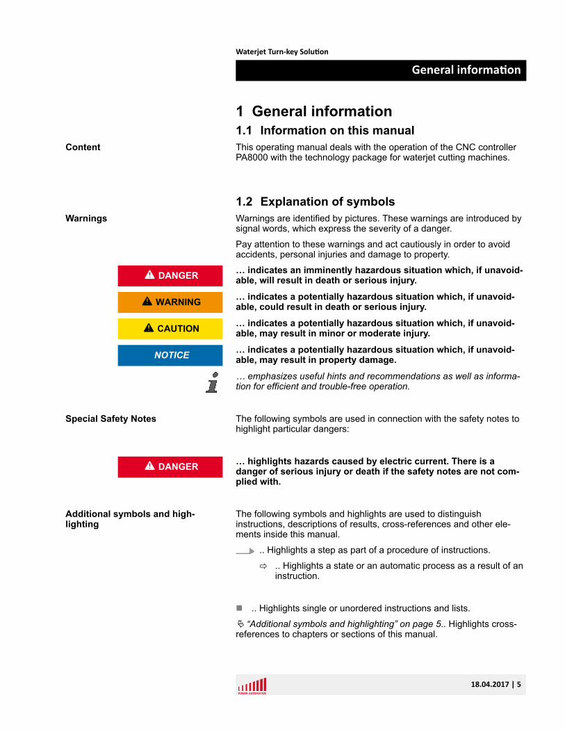
1.2 Explanation of symbolsWarnings are identified by pictures. These warnings are introduced bysignal words, which express the severity of a danger.
Pay attention to these warnings and act cautiously in order to avoidaccidents, personal injuries and damage to property.
… indicates an imminently hazardous situation which, if unavoid-able, will result in death or serious injury.
… indicates a potentially hazardous situation which, if unavoid-able, could result in death or serious injury.
… indicates a potentially hazardous situation which, if unavoid-able, may result in minor or moderate injury.
… indicates a potentially hazardous situation which, if unavoid-able, may result in property damage.
… emphasizes useful hints and recommendations as well as informa-tion for efficient and trouble-free operation.
The following symbols are used in connection with the safety notes tohighlight particular dangers:
… highlights hazards caused by electric current. There is adanger of serious injury or death if the safety notes are not com-plied with.
The following symbols and highlights are used to distinguishinstructions, descriptions of results, cross-references and other ele-ments inside this manual.
.. Highlights a step as part of a procedure of instructions.
ð .. Highlights a state or an automatic process as a result of aninstruction.
n .. Highlights single or unordered instructions and lists.
Ä “Additional symbols and highlighting” on page 5.. Highlights cross-references to chapters or sections of this manual.
Content
Warnings
L DANGER
L WARNING
L CAUTION
NOTICE
Special Safety Notes
L DANGER
Additional symbols and high-lighting
Waterjet Turn-key Solution
General information
18.04.2017 | 5
[Key].. Highlights captions of buttons, fields and other elements of thesoftware's graphical user interface.
“Menu è Submenu è ”.. Highlights a path to access a menu or sub-menu in the software's graphical user interface.
Example/Extract.. Highlights verbatim examples and extracts fromconfiguration files.
1.3 Limitation of liabilityAll information and notes in this operating manual were compiledunder due consideration of valid standards and regulations, thepresent status of technology and our years of knowledge and experi-ence.
Power Automation can not be held liable for damage resulting from:
n disregarding this operating manualn unintended usen employment of untrained personneln unauthorized conversionsn unauthorized modifications to the softwaren technical modificationsn use of unapproved spare partsn use in conjunction with machines not deemed compatible by
Power Automation
In case of customized versions the actual scope of delivery can varyfrom the explanations and representations in this operating manual,because of the utilization of additional options or due to latest technicalchanges.
Apart from this, the obligations agreed upon in the delivery contract,the general terms and conditions, and the delivery conditions of PowerAutomation and the legal regulations valid at the time of contract doapply.
We reserve the right to make technical modifications in order toimprove usability.
1.4 CopyrightThis installation manual is protected by copyright law.
Passing this installation manual on to third parties, duplication of anykind – even in form of excerpts – as well as the use and/or disclosureof the contents without the written consent of Power Automation is notpermitted.
Violations oblige to compensation. The right for further claims remainsreserved.
Liability
Copyright
Waterjet Turn-key Solution
General information
18.04.2017 | 6
1.5 Warranty termsThe material warranty terms are provided in Power Automation's termsand conditions as well as inside the sales documents.
1.6 Customer serviceOur Customer Service is always available for technical information.
For information on whom to contact by phone, fax, e-mail or via theinternet, see Power Automation's address on page 2.
Additionally, Power Automation staff is always interested in receivingnew information and experiences resulting from the use of our prod-ucts, which could be of great value for future improvements.
Material Warranty
Service
Waterjet Turn-key Solution
General information
18.04.2017 | 7
1.7 GlossaryCNC - Computerized Numerical Control
C2C - Contour to contour
HMI - Human Machine Interface
The graphical user interface provided by the PA software.
HSU - Height sensing unit
Kerf - Radius correction of the tool
MTBP - Machine Tool Builder's Panel
Panel including the basic requirements for a machine tooloperator: emergency stop push button, cycle start and stoppush buttons, jog plus and minus push buttons, feed rateand spindle speed override pots and a number of auxiliarypush buttons.
MDI - Manual Data Input
NC-Start - Numerical Control Start Button
NC-Stop - Numerical Control Stop Button
PA - Power Automation
PAMIO - Power Automation Modular Input Output
Extendable Superbus based interface allowing connectionof additional I/O modules.
PC - Personal Computer
PCI - Peripheral Component Interconnect
Personal computer extension for periphery devices con-nected to the motherboard.
RMS - Rotating Measuring Systems (Encoder)
Waterjet Turn-key Solution
General information
18.04.2017 | 8
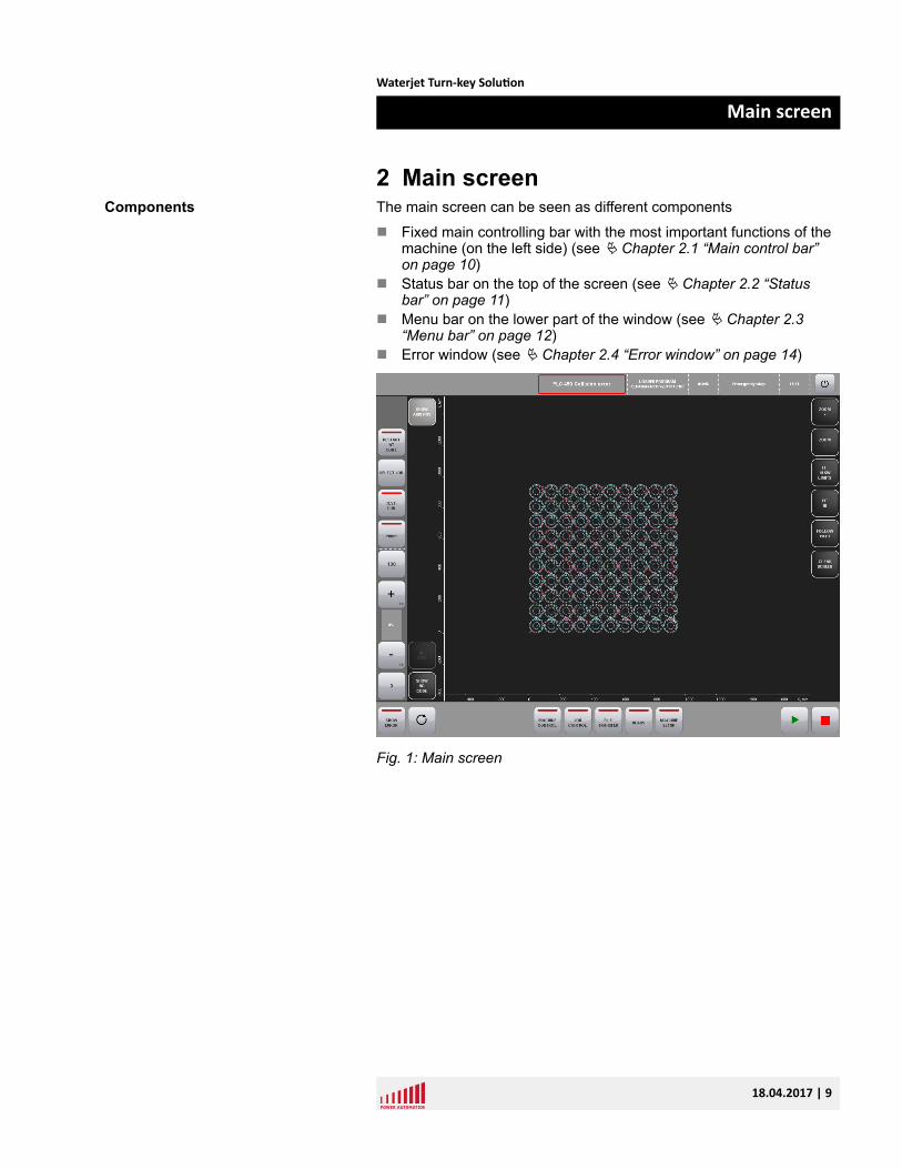
2 Main screenThe main screen can be seen as different components
n Fixed main controlling bar with the most important functions of themachine (on the left side) (see Ä Chapter 2.1 “Main control bar”on page 10)
n Status bar on the top of the screen (see Ä Chapter 2.2 “Statusbar” on page 11)
n Menu bar on the lower part of the window (see Ä Chapter 2.3“Menu bar” on page 12)
n Error window (see Ä Chapter 2.4 “Error window” on page 14)
Fig. 1: Main screen
Components
Waterjet Turn-key Solution
Main screen
18.04.2017 | 9
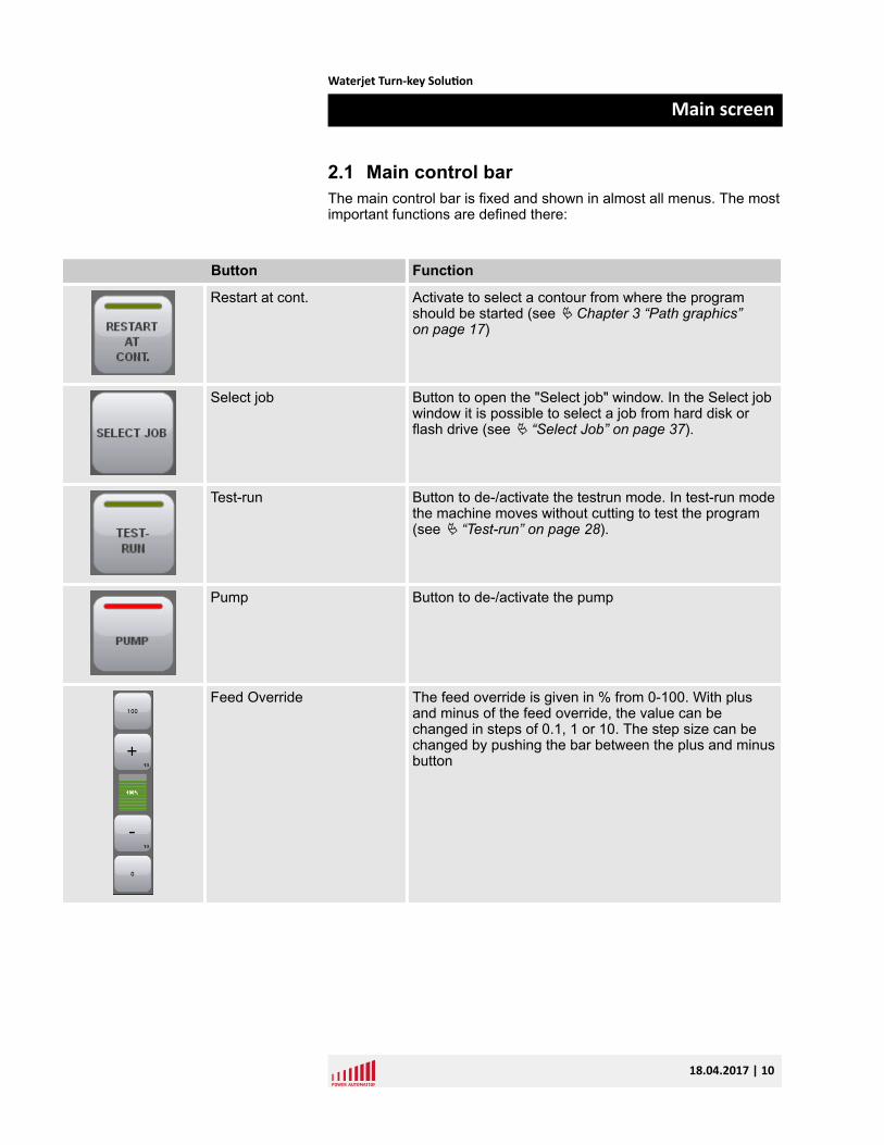
2.1 Main control barThe main control bar is fixed and shown in almost all menus. The mostimportant functions are defined there:
Button Function
Restart at cont. Activate to select a contour from where the programshould be started (see Ä Chapter 3 “Path graphics”on page 17)
Select job Button to open the "Select job" window. In the Select jobwindow it is possible to select a job from hard disk orflash drive (see Ä “Select Job” on page 37).
Test-run Button to de-/activate the testrun mode. In test-run modethe machine moves without cutting to test the program(see Ä “Test-run” on page 28).
Pump Button to de-/activate the pump
Feed Override The feed override is given in % from 0-100. With plusand minus of the feed override, the value can bechanged in steps of 0.1, 1 or 10. The step size can bechanged by pushing the bar between the plus and minusbutton
Waterjet Turn-key Solution
Main screen
18.04.2017 | 10
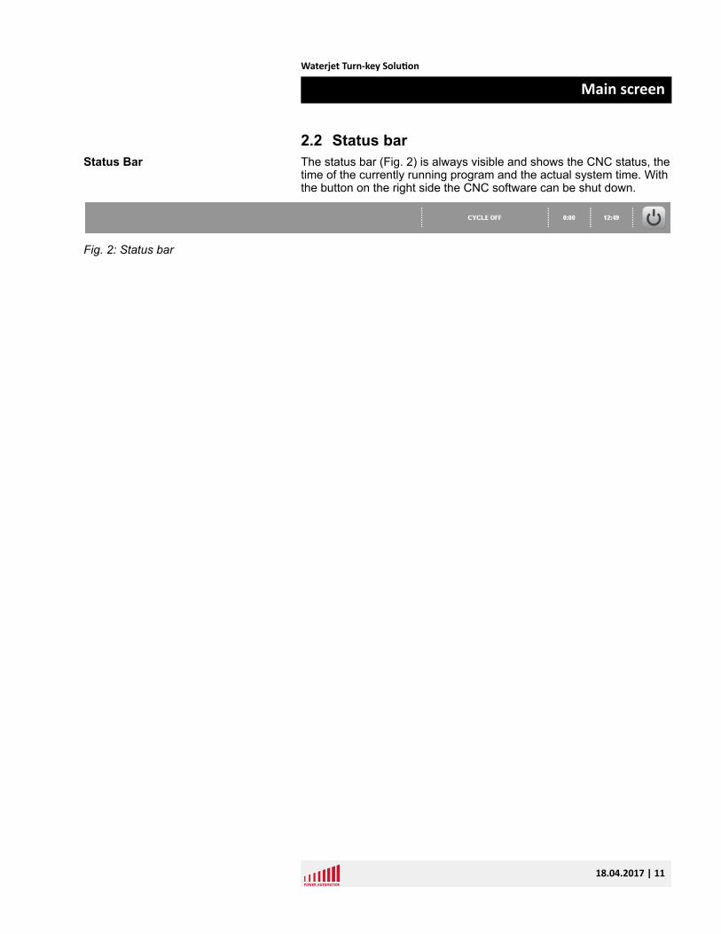
2.2 Status barThe status bar (Fig. 2) is always visible and shows the CNC status, thetime of the currently running program and the actual system time. Withthe button on the right side the CNC software can be shut down.
Fig. 2: Status bar
Status Bar
Waterjet Turn-key Solution
Main screen
18.04.2017 | 11
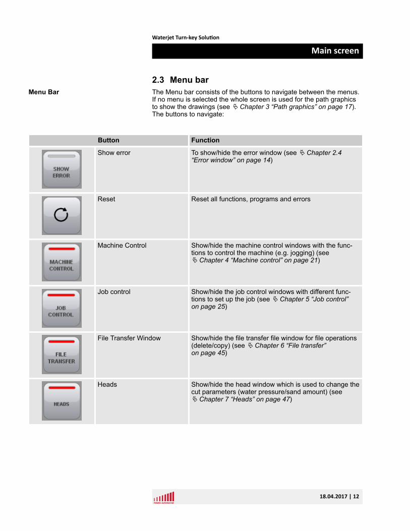
2.3 Menu barThe Menu bar consists of the buttons to navigate between the menus.If no menu is selected the whole screen is used for the path graphicsto show the drawings (see Ä Chapter 3 “Path graphics” on page 17).The buttons to navigate:
Button Function
Show error To show/hide the error window (see Ä Chapter 2.4“Error window” on page 14)
Reset Reset all functions, programs and errors
Machine Control Show/hide the machine control windows with the func-tions to control the machine (e.g. jogging) (seeÄ Chapter 4 “Machine control” on page 21)
Job control Show/hide the job control windows with different func-tions to set up the job (see Ä Chapter 5 “Job control”on page 25)
File Transfer Window Show/hide the file transfer file window for file operations(delete/copy) (see Ä Chapter 6 “File transfer”on page 45)
Heads Show/hide the head window which is used to change thecut parameters (water pressure/sand amount) (seeÄ Chapter 7 “Heads” on page 47)
Menu Bar
Waterjet Turn-key Solution
Main screen
18.04.2017 | 12
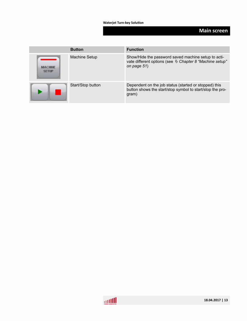
Button Function
Machine Setup Show/Hide the password saved machine setup to acti-vate different options (see Ä Chapter 8 “Machine setup”on page 51)
Start/Stop button Dependent on the job status (started or stopped) thisbutton shows the start/stop symbol to start/stop the pro-gram)
Waterjet Turn-key Solution
Main screen
18.04.2017 | 13
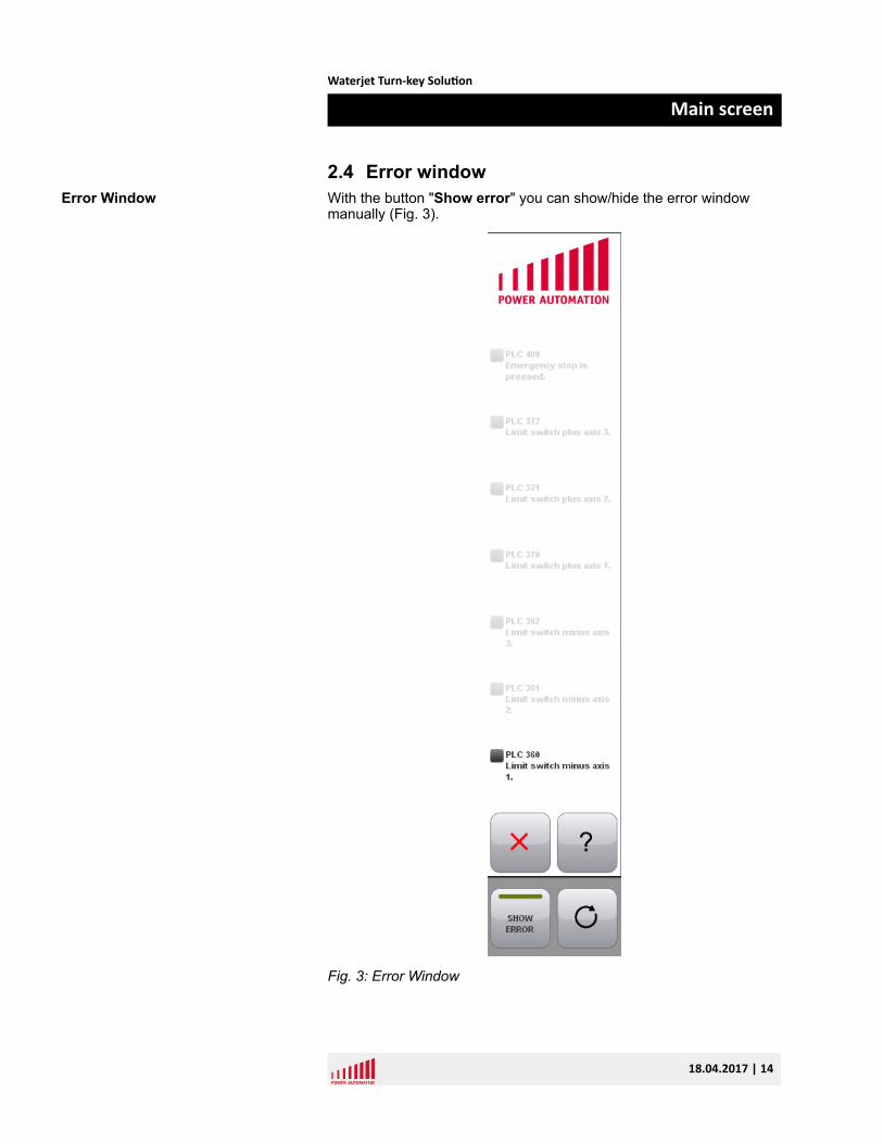
2.4 Error windowWith the button "Show error" you can show/hide the error windowmanually (Fig. 3).
Fig. 3: Error Window
Error Window
Waterjet Turn-key Solution
Main screen
18.04.2017 | 14
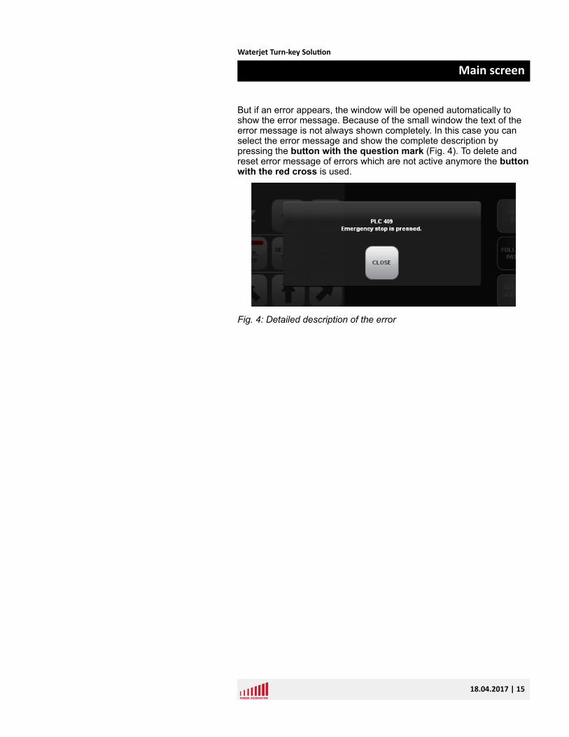
But if an error appears, the window will be opened automatically toshow the error message. Because of the small window the text of theerror message is not always shown completely. In this case you canselect the error message and show the complete description bypressing the button with the question mark (Fig. 4). To delete andreset error message of errors which are not active anymore the buttonwith the red cross is used.
Fig. 4: Detailed description of the error
Waterjet Turn-key Solution
Main screen
18.04.2017 | 15

Waterjet Turn-key Solution
Main screen
18.04.2017 | 16
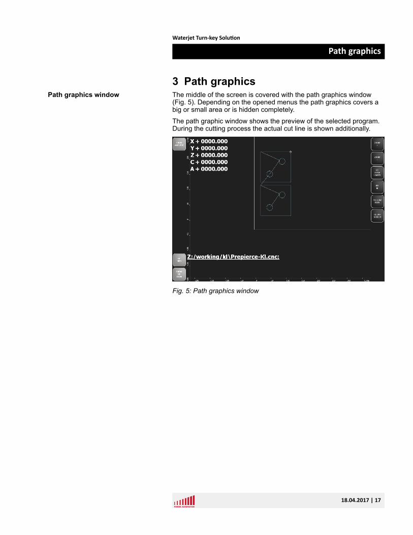
3 Path graphicsThe middle of the screen is covered with the path graphics window(Fig. 5). Depending on the opened menus the path graphics covers abig or small area or is hidden completely.
The path graphic window shows the preview of the selected program.During the cutting process the actual cut line is shown additionally.
Fig. 5: Path graphics window
Path graphics window
Waterjet Turn-key Solution
Path graphics
18.04.2017 | 17
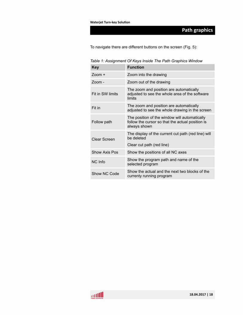
To navigate there are different buttons on the screen (Fig. 5):
Table 1: Assignment Of Keys Inside The Path Graphics WindowKey Function
Zoom + Zoom into the drawing
Zoom - Zoom out of the drawing
Fit in SW limitsThe zoom and position are automaticallyadjusted to see the whole area of the softwarelimits
Fit in The zoom and position are automaticallyadjusted to see the whole drawing in the screen
Follow pathThe position of the window will automaticallyfollow the cursor so that the actual position isalways shown
Clear ScreenThe display of the current cut path (red line) willbe deleted
Clear cut path (red line)
Show Axis Pos Show the positions of all NC axes
NC Info Show the program path and name of theselected program
Show NC Code Show the actual and the next two blocks of thecurrenty running program
Waterjet Turn-key Solution
Path graphics
18.04.2017 | 18
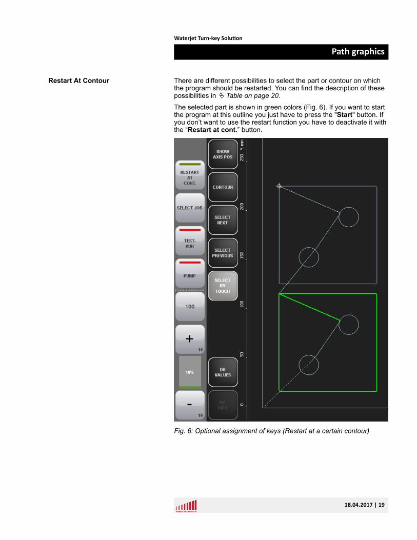
There are different possibilities to select the part or contour on whichthe program should be restarted. You can find the description of thesepossibilities in Ä Table on page 20.
The selected part is shown in green colors (Fig. 6). If you want to startthe program at this outline you just have to press the "Start" button. Ifyou don’t want to use the restart function you have to deactivate it withthe “Restart at cont.” button.
Fig. 6: Optional assignment of keys (Restart at a certain contour)
Restart At Contour
Waterjet Turn-key Solution
Path graphics
18.04.2017 | 19
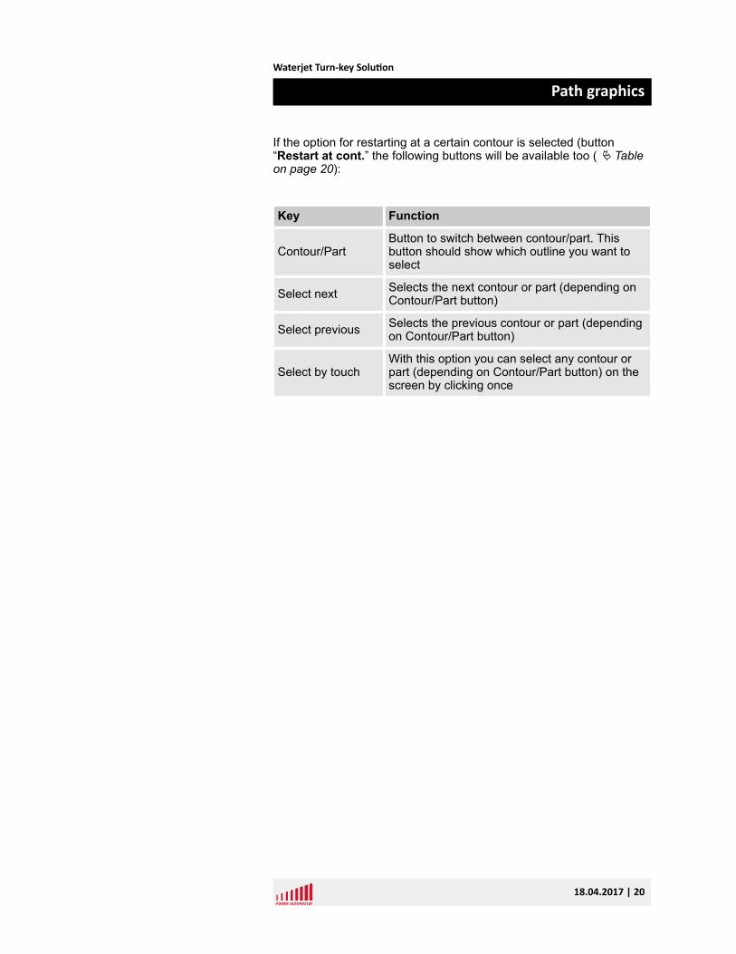
If the option for restarting at a certain contour is selected (button“Restart at cont.” the following buttons will be available too ( Ä Tableon page 20):
Key Function
Contour/PartButton to switch between contour/part. Thisbutton should show which outline you want toselect
Select next Selects the next contour or part (depending onContour/Part button)
Select previous Selects the previous contour or part (dependingon Contour/Part button)
Select by touchWith this option you can select any contour orpart (depending on Contour/Part button) on thescreen by clicking once
Waterjet Turn-key Solution
Path graphics
18.04.2017 | 20
4 Machine controlThe machine control window is used for controlling the machine. Thereare defined different move options, jog button, feed override settings.The machine control is divided into two windows which are positionedon the left and right side of the screen.
Machine Control Window
Waterjet Turn-key Solution
Machine control
18.04.2017 | 21
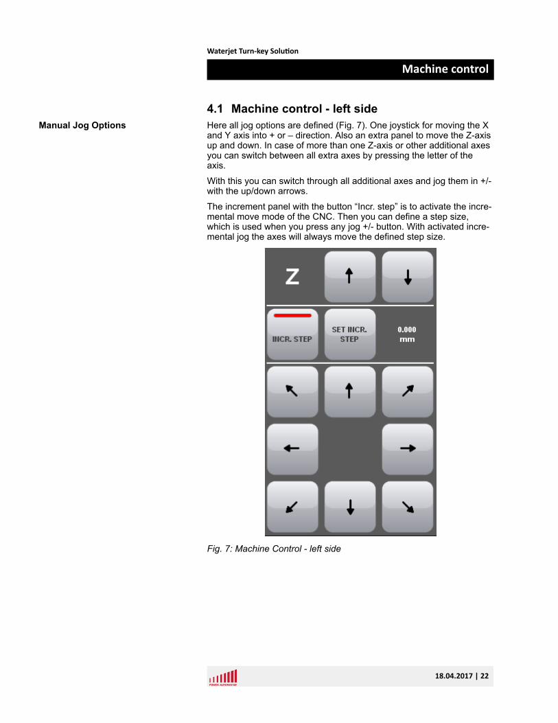
4.1 Machine control - left sideHere all jog options are defined (Fig. 7). One joystick for moving the Xand Y axis into + or – direction. Also an extra panel to move the Z-axisup and down. In case of more than one Z-axis or other additional axesyou can switch between all extra axes by pressing the letter of theaxis.
With this you can switch through all additional axes and jog them in +/-with the up/down arrows.
The increment panel with the button “Incr. step” is to activate the incre-mental move mode of the CNC. Then you can define a step size,which is used when you press any jog +/- button. With activated incre-mental jog the axes will always move the defined step size.
Fig. 7: Machine Control - left side
Manual Jog Options
Waterjet Turn-key Solution
Machine control
18.04.2017 | 22
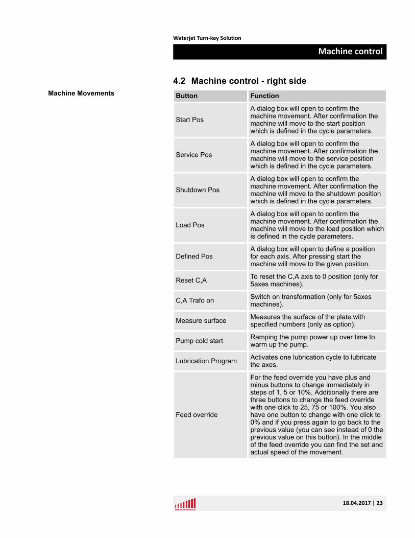
4.2 Machine control - right sideButton Function
Start PosA dialog box will open to confirm themachine movement. After confirmation themachine will move to the start positionwhich is defined in the cycle parameters.
Service PosA dialog box will open to confirm themachine movement. After confirmation themachine will move to the service positionwhich is defined in the cycle parameters.
Shutdown PosA dialog box will open to confirm themachine movement. After confirmation themachine will move to the shutdown positionwhich is defined in the cycle parameters.
Load PosA dialog box will open to confirm themachine movement. After confirmation themachine will move to the load position whichis defined in the cycle parameters.
Defined PosA dialog box will open to define a positionfor each axis. After pressing start themachine will move to the given position.
Reset C,A To reset the C,A axis to 0 position (only for5axes machines).
C,A Trafo on Switch on transformation (only for 5axesmachines).
Measure surface Measures the surface of the plate withspecified numbers (only as option).
Pump cold start Ramping the pump power up over time towarm up the pump.
Lubrication Program Activates one lubrication cycle to lubricatethe axes.
Feed override
For the feed override you have plus andminus buttons to change immediately insteps of 1, 5 or 10%. Additionally there arethree buttons to change the feed overridewith one click to 25, 75 or 100%. You alsohave one button to change with one click to0% and if you press again to go back to theprevious value (you can see instead of 0 theprevious value on this button). In the middleof the feed override you can find the set andactual speed of the movement.
Machine Movements
Waterjet Turn-key Solution
Machine control
18.04.2017 | 23
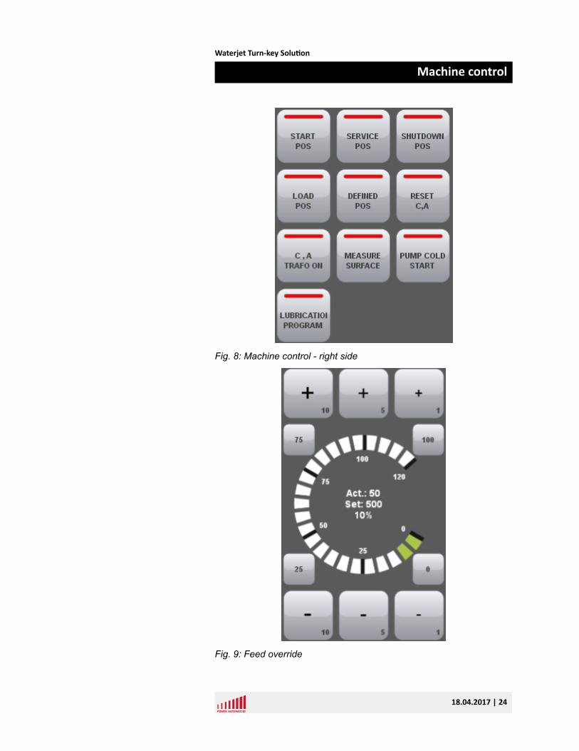
Fig. 8: Machine control - right side
Fig. 9: Feed override
Waterjet Turn-key Solution
Machine control
18.04.2017 | 24
5 Job controlThe job control window has two different views. The view and function-ality is dependent on the actual CNC status. If the program is activeyou can see functions which are made to affect the machine during thecutting process. If no program is active all functions are displayedwhich are used for setting up parameters before the start of a program.
5.1 Job control cycle off – left side
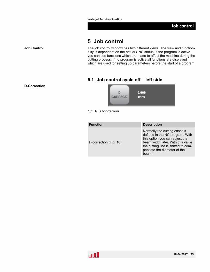
Fig. 10: D-correction
Function Description
D-correction (Fig. 10)
Normally the cutting offset isdefined in the NC program. Withthis option you can adjust thebeam width later. With this valuethe cutting line is shifted to com-pensate the diameter of thebeam.
Job Control
D-Correction
Waterjet Turn-key Solution
Job control
18.04.2017 | 25
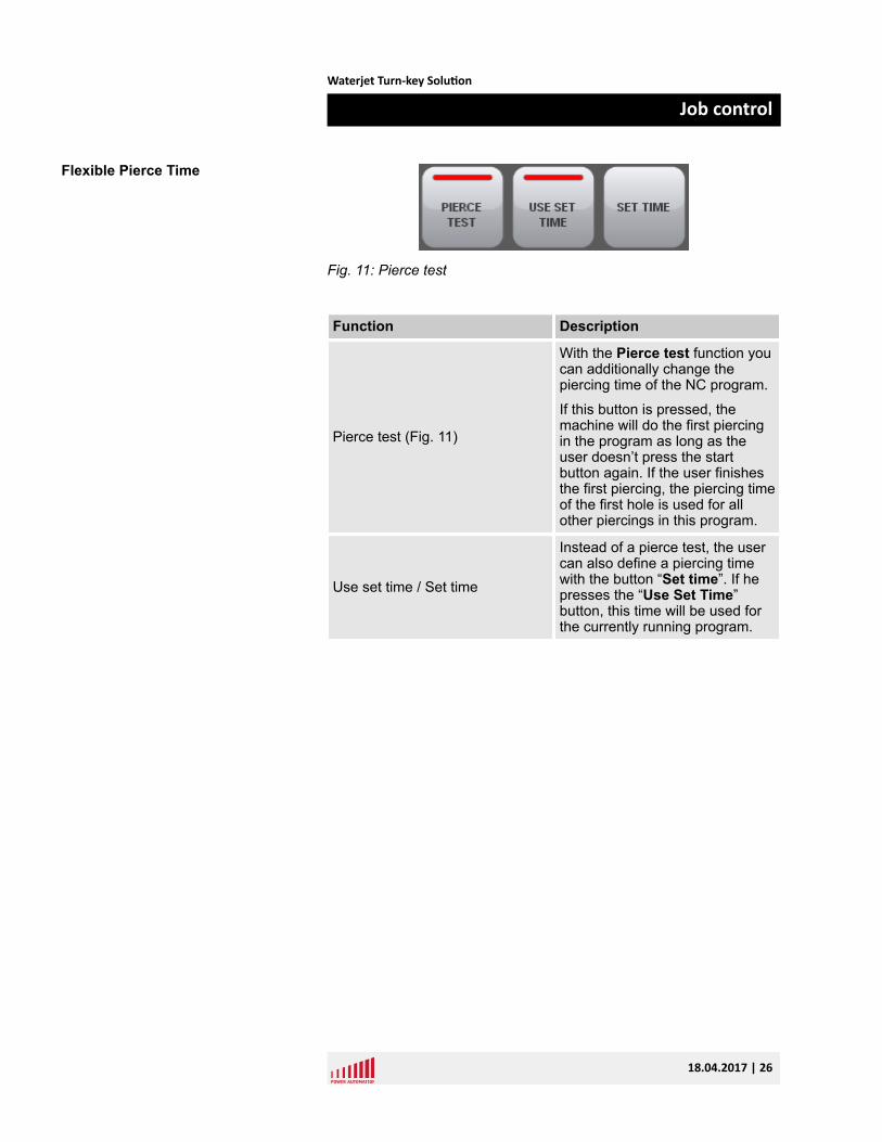
Fig. 11: Pierce test
Function Description
Pierce test (Fig. 11)
With the Pierce test function youcan additionally change thepiercing time of the NC program.
If this button is pressed, themachine will do the first piercingin the program as long as theuser doesn’t press the startbutton again. If the user finishesthe first piercing, the piercing timeof the first hole is used for allother piercings in this program.
Use set time / Set time
Instead of a pierce test, the usercan also define a piercing timewith the button “Set time”. If hepresses the “Use Set Time”button, this time will be used forthe currently running program.
Flexible Pierce Time
Waterjet Turn-key Solution
Job control
18.04.2017 | 26
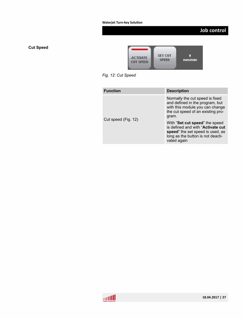
Fig. 12: Cut Speed
Function Description
Cut speed (Fig. 12)
Normally the cut speed is fixedand defined in the program, butwith this module you can changethe cut speed of an existing pro-gram.
With “Set cut speed” the speedis defined and with “Activate cutspeed” the set speed is used, aslong as the button is not deacti-vated again
Cut Speed
Waterjet Turn-key Solution
Job control
18.04.2017 | 27
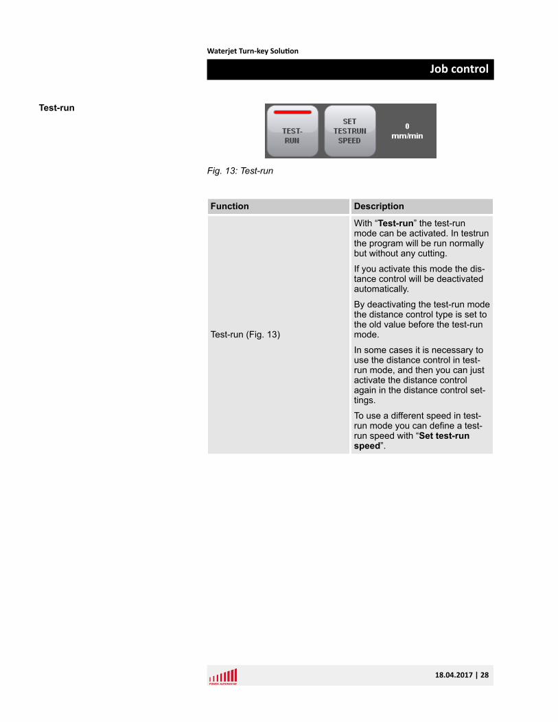
Fig. 13: Test-run
Function Description
Test-run (Fig. 13)
With “Test-run” the test-runmode can be activated. In testrunthe program will be run normallybut without any cutting.
If you activate this mode the dis-tance control will be deactivatedautomatically.
By deactivating the test-run modethe distance control type is set tothe old value before the test-runmode.
In some cases it is necessary touse the distance control in test-run mode, and then you can justactivate the distance controlagain in the distance control set-tings.
To use a different speed in test-run mode you can define a test-run speed with “Set test-runspeed”.
Test-run
Waterjet Turn-key Solution
Job control
18.04.2017 | 28
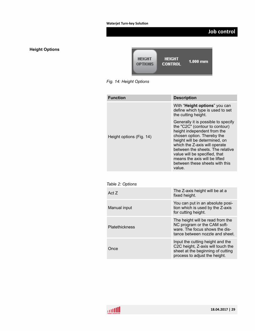
Fig. 14: Height Options
Function Description
Height options (Fig. 14)
With “Height options” you candefine which type is used to setthe cutting height.
Generally it is possible to specifythe "C2C" (contour to contour)height independent from thechosen option. Thereby theheight will be determined, onwhich the Z-axis will operatebetween the sheets. The relativevalue will be specified, thatmeans the axis will be liftedbetween these sheets with thisvalue.
Table 2: Options
Act Z The Z-axis height will be at afixed height.
Manual inputYou can put in an absolute posi-tion which is used by the Z-axisfor cutting height.
PlatethicknessThe height will be read from theNC program or the CAM soft-ware. The focus shows the dis-tance between nozzle and sheet.
OnceInput the cutting height and theC2C height, Z-axis will touch thesheet at the beginning of cuttingprocess to adjust the height.
Height Options
Waterjet Turn-key Solution
Job control
18.04.2017 | 29
At pierceInput the cutting height, the Z-axis will touch at each piercing toget the height.
Plate comp
n Input the cutting height, thesheet width and length andthe number of points in X andY direction.
n The machine will measurethe distance on the wholesheet on the X and Y pointsand save them.
n After finishing measurementthe machine will start cutting.Then the height will be com-pensated automatically.
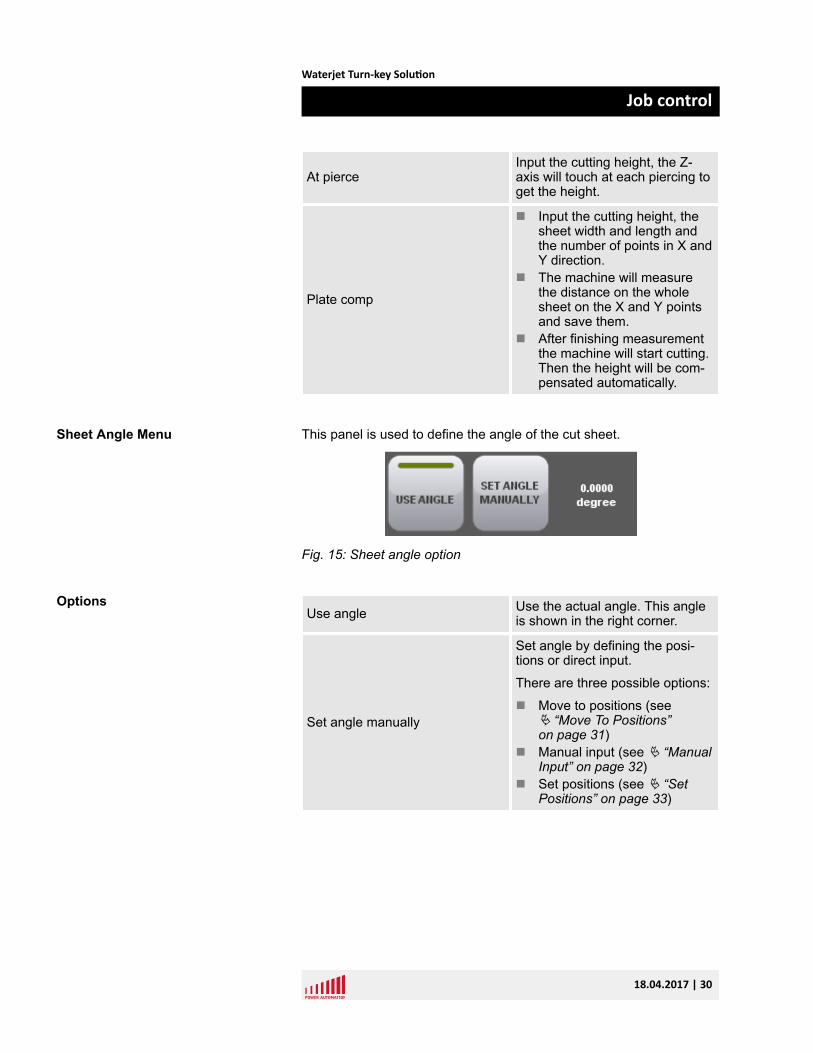
This panel is used to define the angle of the cut sheet.
Fig. 15: Sheet angle option
Use angle Use the actual angle. This angleis shown in the right corner.
Set angle manually
Set angle by defining the posi-tions or direct input.
There are three possible options:
n Move to positions (seeÄ “Move To Positions”on page 31)
n Manual input (see Ä “ManualInput” on page 32)
n Set positions (see Ä “SetPositions” on page 33)
Sheet Angle Menu
Options
Waterjet Turn-key Solution
Job control
18.04.2017 | 30
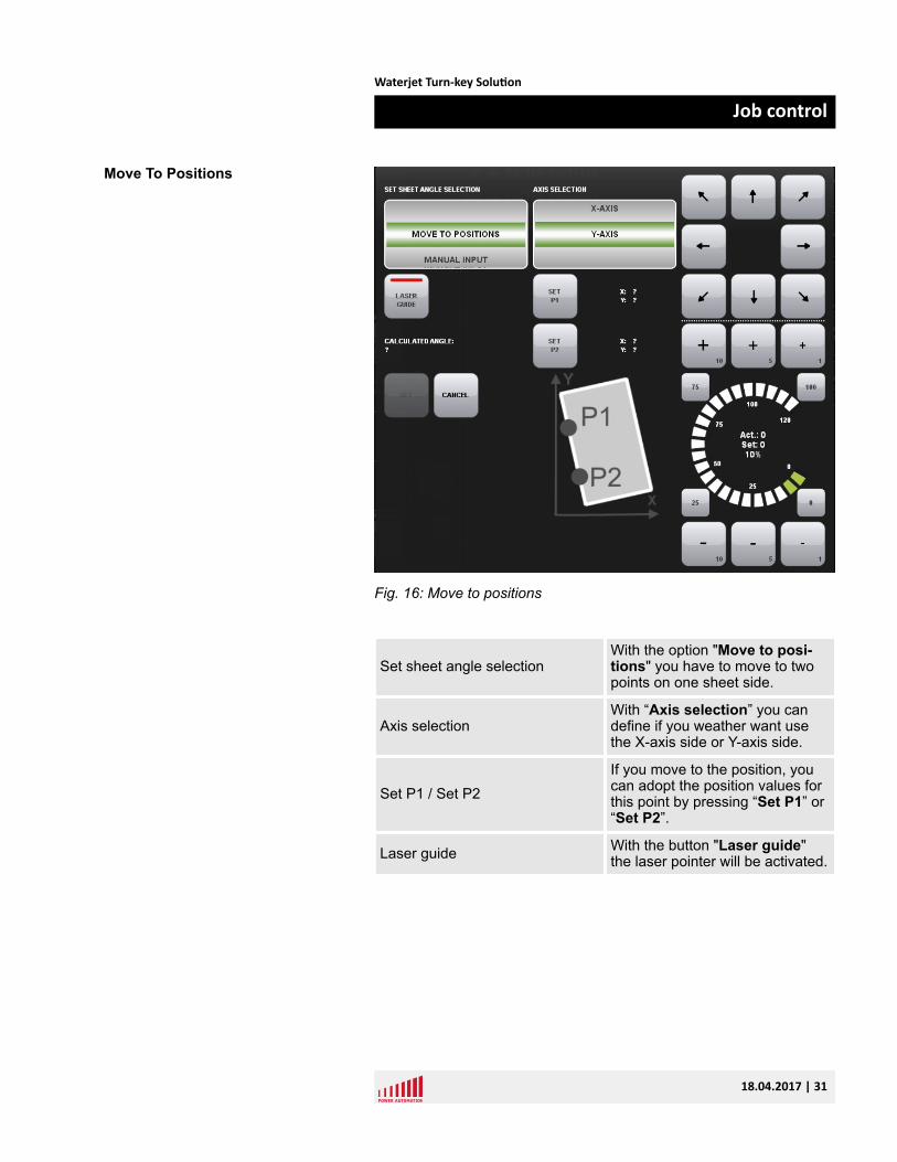
Fig. 16: Move to positions
Set sheet angle selectionWith the option "Move to posi-tions" you have to move to twopoints on one sheet side.
Axis selectionWith “Axis selection” you candefine if you weather want usethe X-axis side or Y-axis side.
Set P1 / Set P2If you move to the position, youcan adopt the position values forthis point by pressing “Set P1” or“Set P2”.
Laser guide With the button "Laser guide"the laser pointer will be activated.
Move To Positions
Waterjet Turn-key Solution
Job control
18.04.2017 | 31
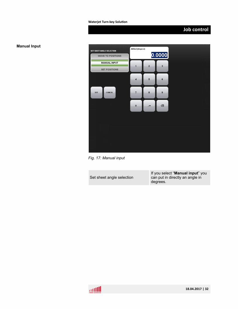
Fig. 17: Manual input
Set sheet angle selectionIf you select “Manual input” youcan put in directly an angle indegrees.
Manual Input
Waterjet Turn-key Solution
Job control
18.04.2017 | 32
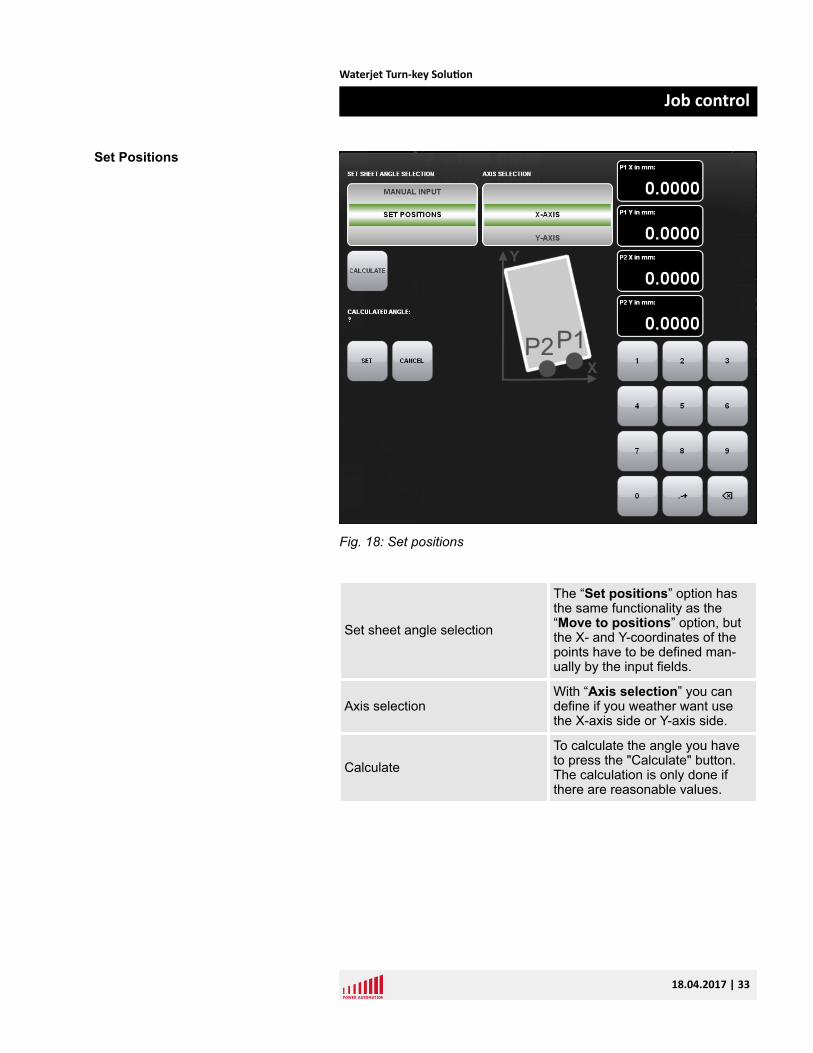
Fig. 18: Set positions
Set sheet angle selection
The “Set positions” option hasthe same functionality as the“Move to positions” option, butthe X- and Y-coordinates of thepoints have to be defined man-ually by the input fields.
Axis selectionWith “Axis selection” you candefine if you weather want usethe X-axis side or Y-axis side.
CalculateTo calculate the angle you haveto press the "Calculate" button.The calculation is only done ifthere are reasonable values.
Set Positions
Waterjet Turn-key Solution
Job control
18.04.2017 | 33
5.2 Job control cycle off – right side
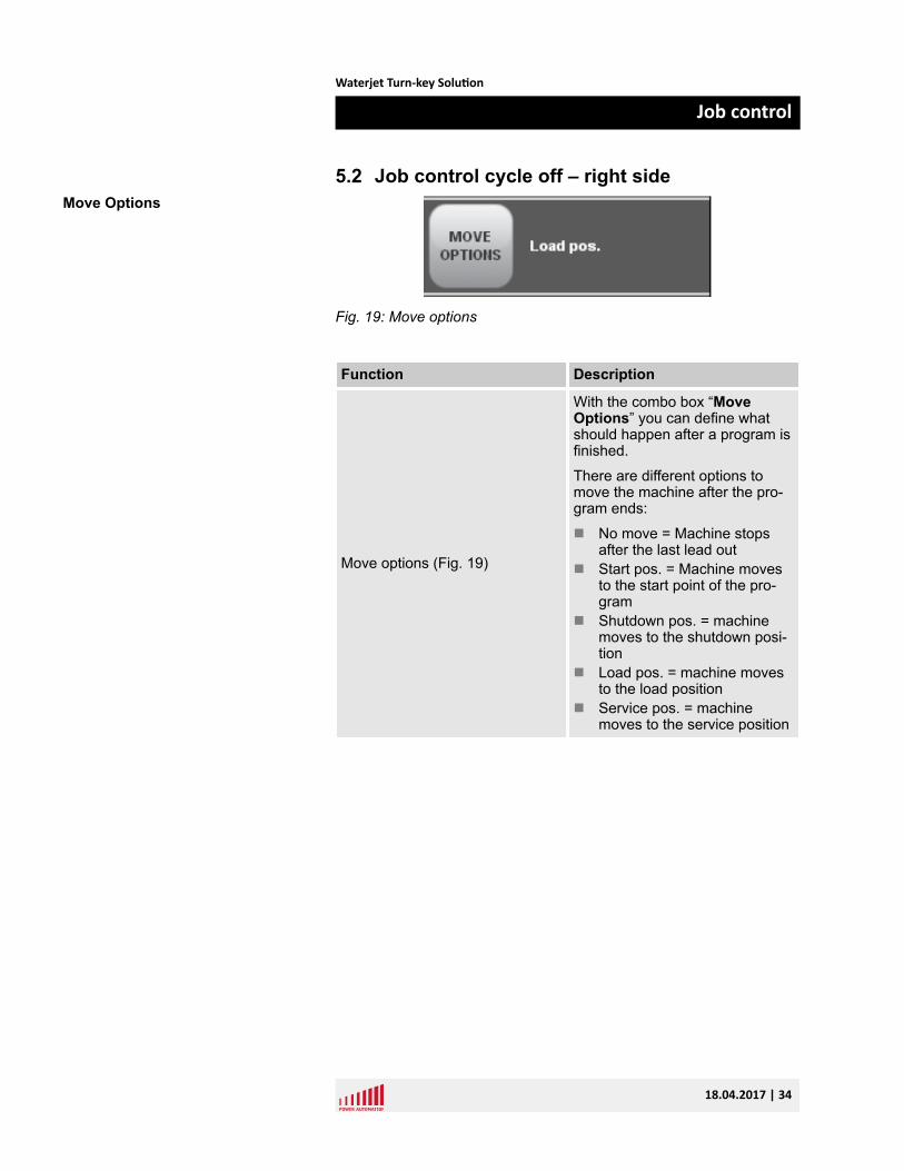
Fig. 19: Move options
Function Description
Move options (Fig. 19)
With the combo box “MoveOptions” you can define whatshould happen after a program isfinished.
There are different options tomove the machine after the pro-gram ends:
n No move = Machine stopsafter the last lead out
n Start pos. = Machine movesto the start point of the pro-gram
n Shutdown pos. = machinemoves to the shutdown posi-tion
n Load pos. = machine movesto the load position
n Service pos. = machinemoves to the service position
Move Options
Waterjet Turn-key Solution
Job control
18.04.2017 | 34
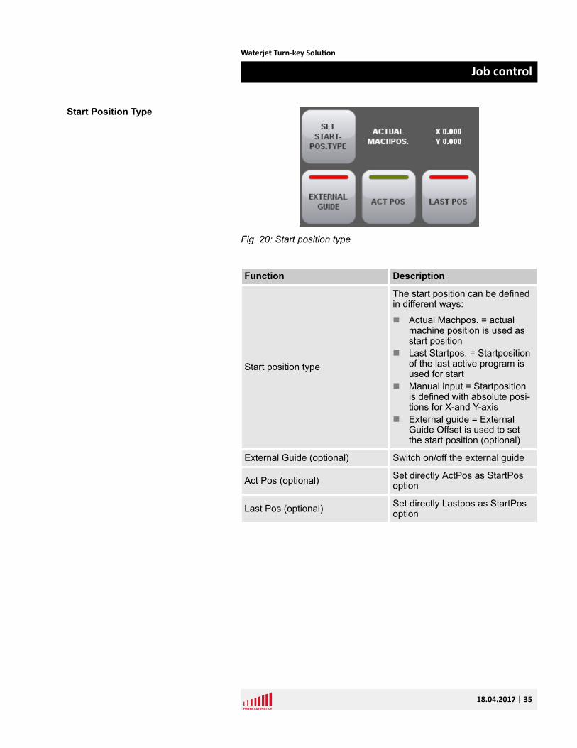
Fig. 20: Start position type
Function Description
Start position type
The start position can be definedin different ways:
n Actual Machpos. = actualmachine position is used asstart position
n Last Startpos. = Startpositionof the last active program isused for start
n Manual input = Startpositionis defined with absolute posi-tions for X-and Y-axis
n External guide = ExternalGuide Offset is used to setthe start position (optional)
External Guide (optional) Switch on/off the external guide
Act Pos (optional) Set directly ActPos as StartPosoption
Last Pos (optional) Set directly Lastpos as StartPosoption
Start Position Type
Waterjet Turn-key Solution
Job control
18.04.2017 | 35
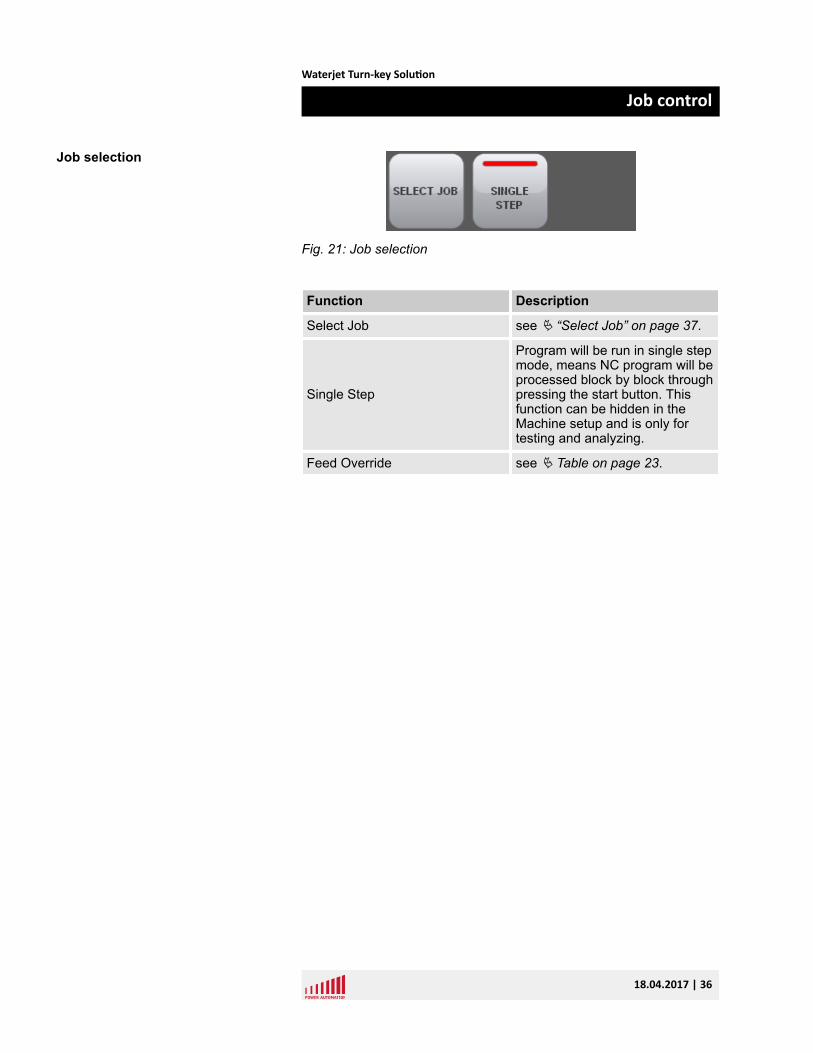
Fig. 21: Job selection
Function Description
Select Job see Ä “Select Job” on page 37.
Single Step
Program will be run in single stepmode, means NC program will beprocessed block by block throughpressing the start button. Thisfunction can be hidden in theMachine setup and is only fortesting and analyzing.
Feed Override see Ä Table on page 23.
Job selection
Waterjet Turn-key Solution
Job control
18.04.2017 | 36
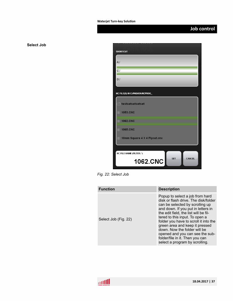
Fig. 22: Select Job
Function Description
Select Job (Fig. 22)
Popup to select a job from harddisk or flash drive. The disk/foldercan be selected by scrolling upand down. If you put in letters inthe edit field, the list will be fil-tered to this input. To open afolder you have to scroll it into thegreen area and keep it presseddown. Now the folder will beopened and you can see the sub-folder/file in it. Then you canselect a program by scrolling.
Select Job
Waterjet Turn-key Solution
Job control
18.04.2017 | 37
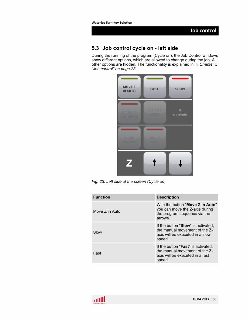
5.3 Job control cycle on - left sideDuring the running of the program (Cycle on), the Job Control windowsshow different options, which are allowed to change during the job. Allother options are hidden. The functionality is explained in Ä Chapter 5“Job control” on page 25.
Fig. 23: Left side of the screen (Cycle on)
Function Description
Move Z in AutoWith the button "Move Z in Auto"you can move the Z-axis duringthe program sequence via thearrows.
SlowIf the button "Slow" is activated,the manual movement of the Z-axis will be executed in a slowspeed.
FastIf the button "Fast" is activated,the manual movement of the Z-axis will be executed in a fastspeed.
Waterjet Turn-key Solution
Job control
18.04.2017 | 38
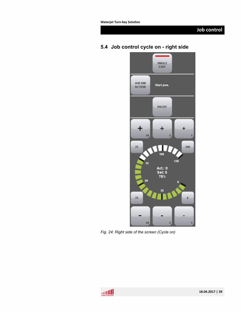
5.4 Job control cycle on - right side
Fig. 24: Right side of the screen (Cycle on)
Waterjet Turn-key Solution
Job control
18.04.2017 | 39
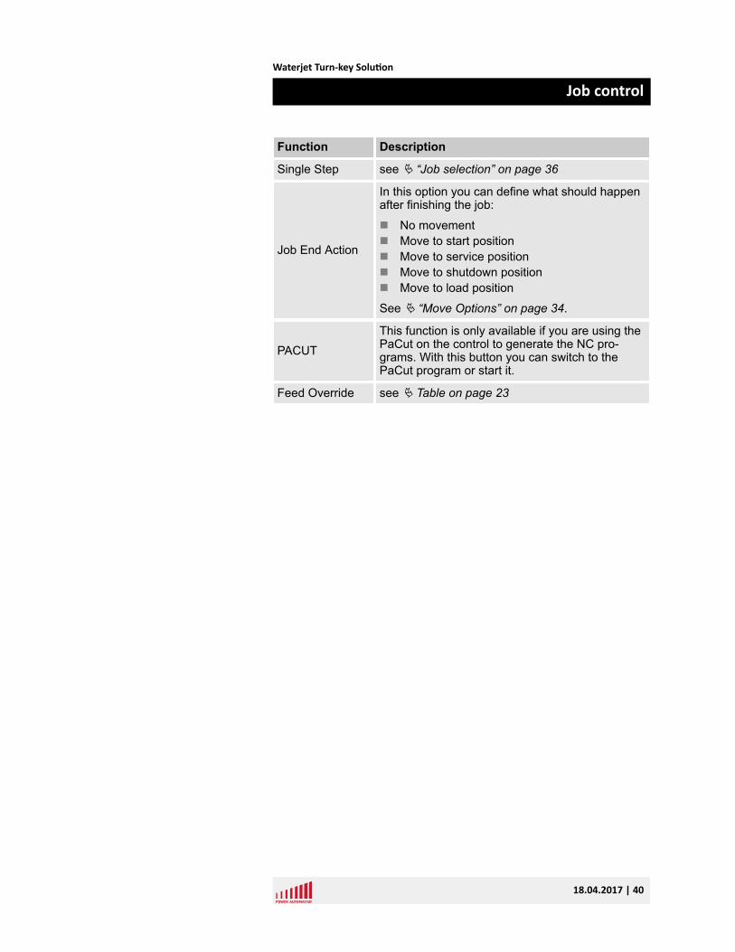
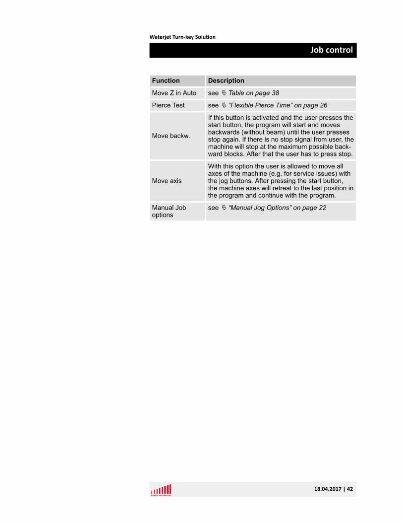
Function Description
Single Step see Ä “Job selection” on page 36
Job End Action
In this option you can define what should happenafter finishing the job:
n No movementn Move to start positionn Move to service positionn Move to shutdown positionn Move to load position
See Ä “Move Options” on page 34.
PACUTThis function is only available if you are using thePaCut on the control to generate the NC pro-grams. With this button you can switch to thePaCut program or start it.
Feed Override see Ä Table on page 23
Waterjet Turn-key Solution
Job control
18.04.2017 | 40
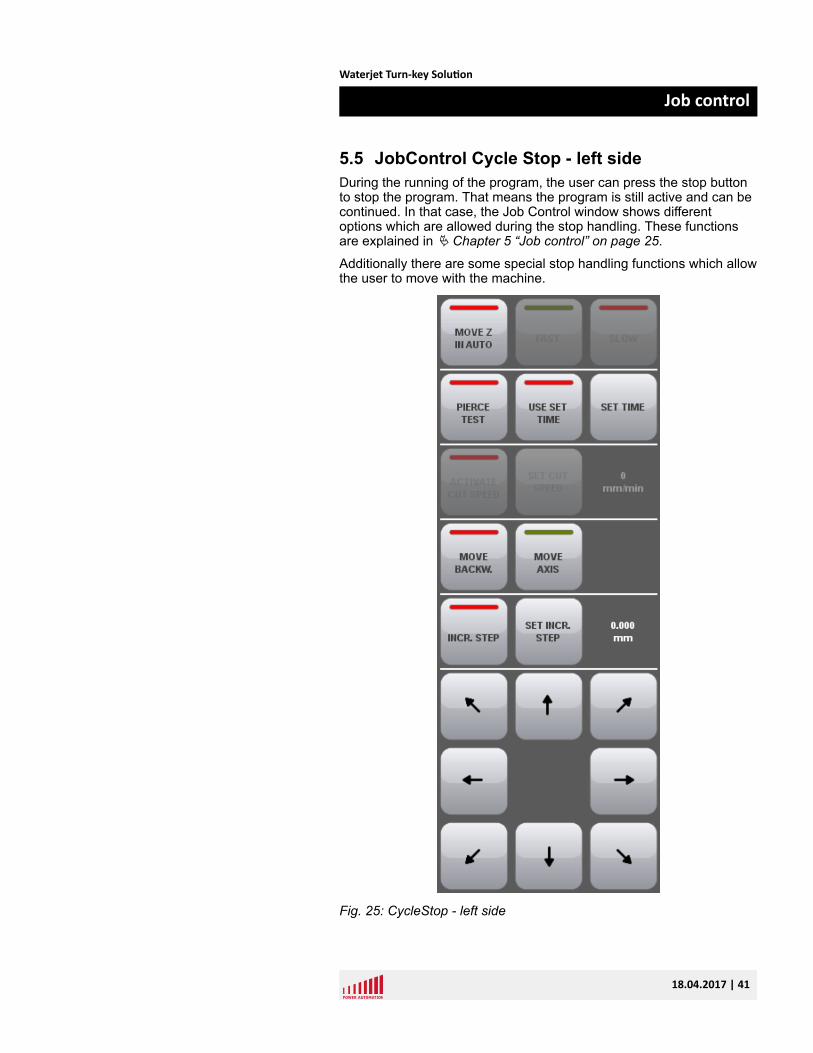
5.5 JobControl Cycle Stop - left sideDuring the running of the program, the user can press the stop buttonto stop the program. That means the program is still active and can becontinued. In that case, the Job Control window shows differentoptions which are allowed during the stop handling. These functionsare explained in Ä Chapter 5 “Job control” on page 25.
Additionally there are some special stop handling functions which allowthe user to move with the machine.
Fig. 25: CycleStop - left side
Waterjet Turn-key Solution
Job control
18.04.2017 | 41
Function Description
Move Z in Auto see Ä Table on page 38
Pierce Test see Ä “Flexible Pierce Time” on page 26
Move backw.
If this button is activated and the user presses thestart button, the program will start and movesbackwards (without beam) until the user pressesstop again. If there is no stop signal from user, themachine will stop at the maximum possible back-ward blocks. After that the user has to press stop.
Move axis
With this option the user is allowed to move allaxes of the machine (e.g. for service issues) withthe jog buttons. After pressing the start button,the machine axes will retreat to the last position inthe program and continue with the program.
Manual Joboptions
see Ä “Manual Jog Options” on page 22
Waterjet Turn-key Solution
Job control
18.04.2017 | 42
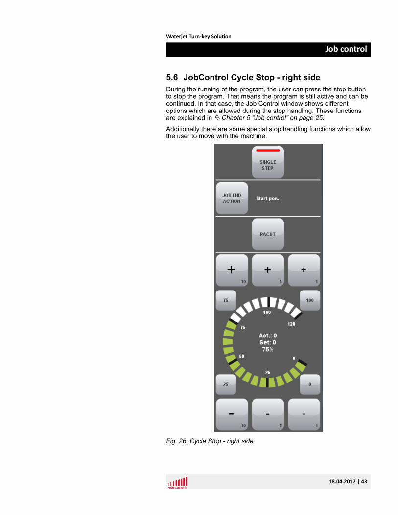
5.6 JobControl Cycle Stop - right sideDuring the running of the program, the user can press the stop buttonto stop the program. That means the program is still active and can becontinued. In that case, the Job Control window shows differentoptions which are allowed during the stop handling. These functionsare explained in Ä Chapter 5 “Job control” on page 25.
Additionally there are some special stop handling functions which allowthe user to move with the machine.
Fig. 26: Cycle Stop - right side
Waterjet Turn-key Solution
Job control
18.04.2017 | 43
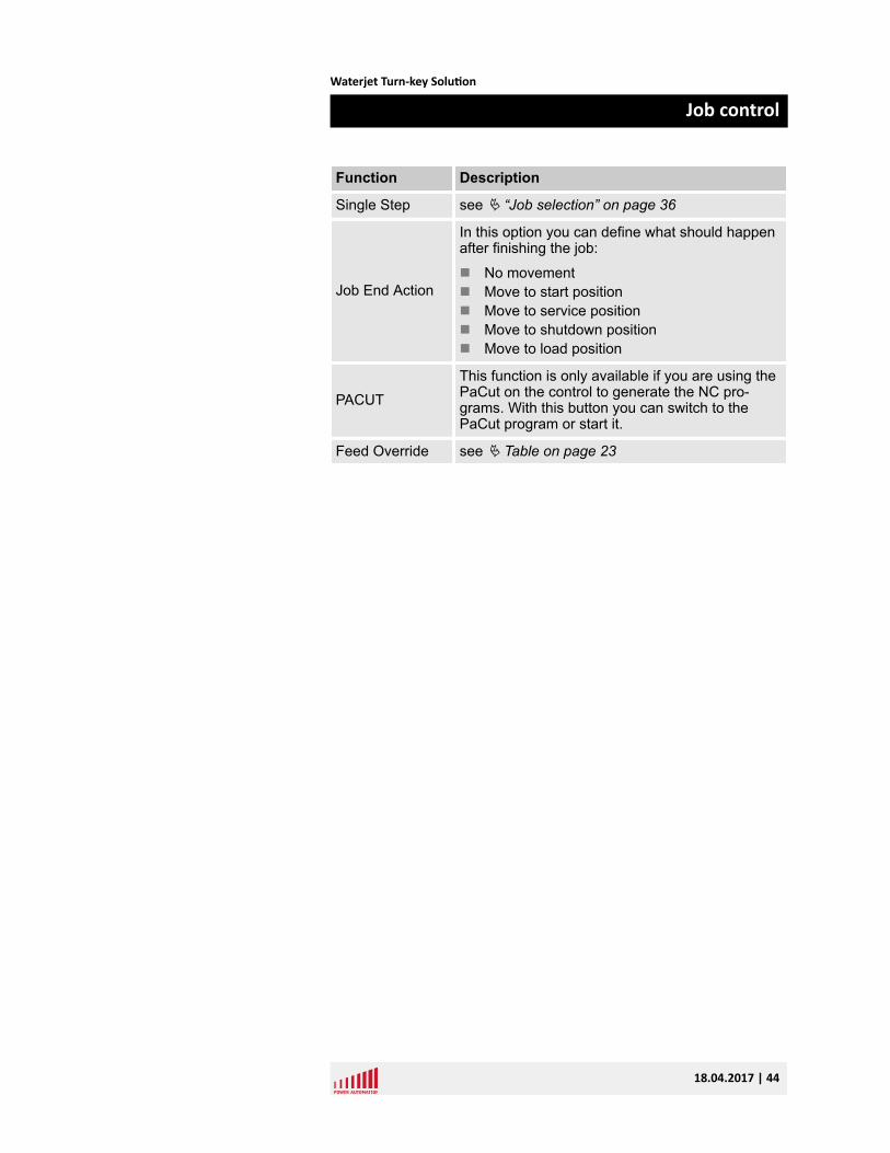
Function Description
Single Step see Ä “Job selection” on page 36
Job End Action
In this option you can define what should happenafter finishing the job:
n No movementn Move to start positionn Move to service positionn Move to shutdown positionn Move to load position
PACUTThis function is only available if you are using thePaCut on the control to generate the NC pro-grams. With this button you can switch to thePaCut program or start it.
Feed Override see Ä Table on page 23
Waterjet Turn-key Solution
Job control
18.04.2017 | 44
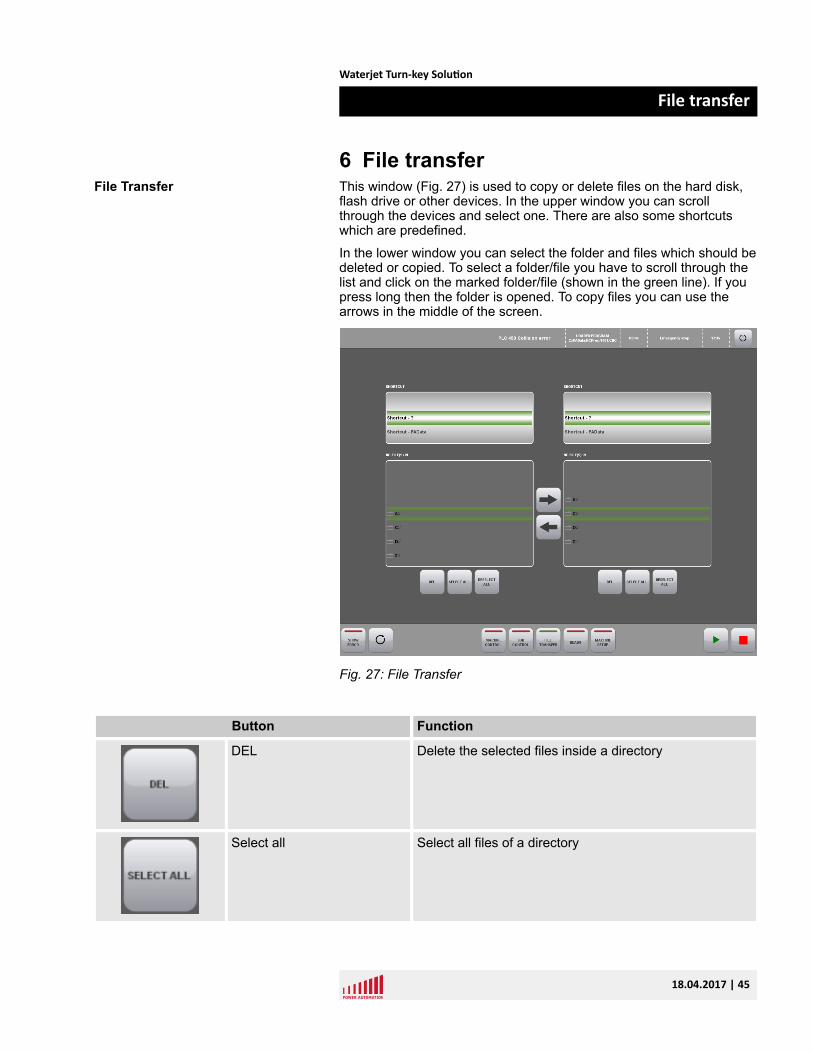
6 File transferThis window (Fig. 27) is used to copy or delete files on the hard disk,flash drive or other devices. In the upper window you can scrollthrough the devices and select one. There are also some shortcutswhich are predefined.
In the lower window you can select the folder and files which should bedeleted or copied. To select a folder/file you have to scroll through thelist and click on the marked folder/file (shown in the green line). If youpress long then the folder is opened. To copy files you can use thearrows in the middle of the screen.
Fig. 27: File Transfer
Button Function
DEL Delete the selected files inside a directory
Select all Select all files of a directory
File Transfer
Waterjet Turn-key Solution
File transfer
18.04.2017 | 45
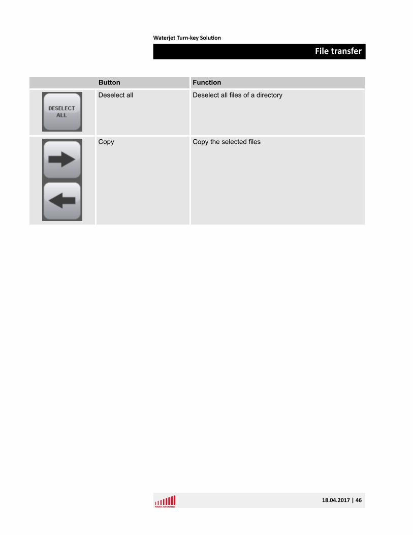
Button Function
Deselect all Deselect all files of a directory
Copy Copy the selected files
Waterjet Turn-key Solution
File transfer
18.04.2017 | 46
7 HeadsThe Heads window (Fig. 28) shows all heads of the machine. Thereare panels for each head to set the specific settings. With the “Water”and “Sand” buttons you can activate/deactivate the water valve or thesand feeding.
This can be done all the time (with activated or deactivated program).With program start the water and sand will be activated automaticallydepending on the program but you can interact at any time.
If you want to change the water pressure or the sand amount you haveactivate the button “Change cut par”. Then you are allowed to changethe water pressure with the plus and minus button in steps of "100" or"500".
To change the step size you have to click on the bar on the right side.
Also the sand amount can be changed in the same way. Here thesteps are "10" and "100".
If you want to go on with the values from the program you have todeactivate the “Change cut par” button. Then the pressure will bereset with the next part/contour.
Heads Window
Waterjet Turn-key Solution
Heads
18.04.2017 | 47
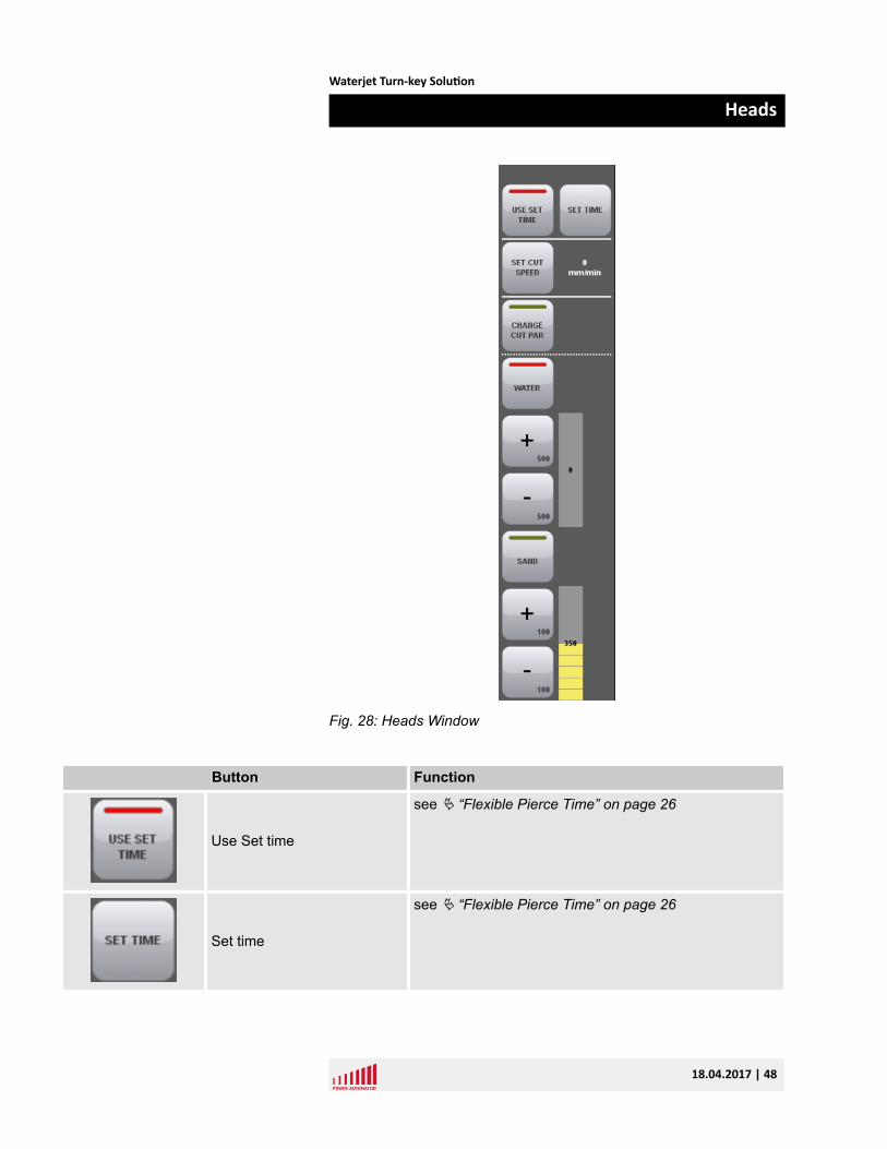
Fig. 28: Heads Window
Button Function
Use Set time
see Ä “Flexible Pierce Time” on page 26
Set time
see Ä “Flexible Pierce Time” on page 26
Waterjet Turn-key Solution
Heads
18.04.2017 | 48
Button Function
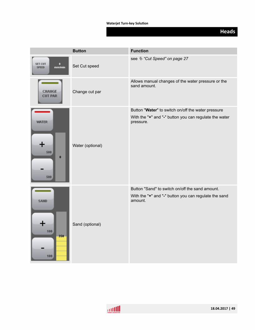
Set Cut speed
see Ä “Cut Speed” on page 27
Change cut par
Allows manual changes of the water pressure or thesand amount.
Water (optional)
Button "Water" to switch on/off the water pressure
With the "+" and "-" button you can regulate the waterpressure.
Sand (optional)
Button "Sand" to switch on/off the sand amount.
With the "+" and "-" button you can regulate the sandamount.
Waterjet Turn-key Solution
Heads
18.04.2017 | 49

Waterjet Turn-key Solution
Heads
18.04.2017 | 50
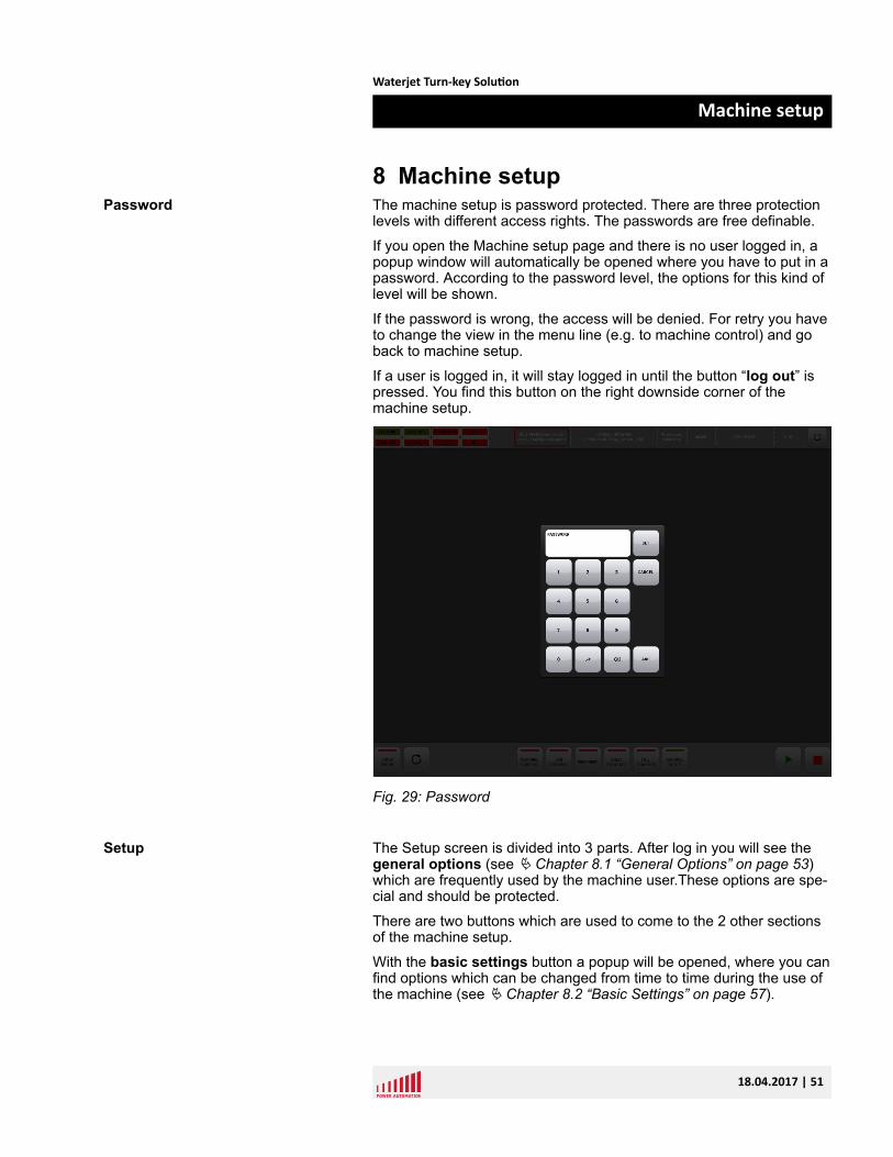
8 Machine setupThe machine setup is password protected. There are three protectionlevels with different access rights. The passwords are free definable.
If you open the Machine setup page and there is no user logged in, apopup window will automatically be opened where you have to put in apassword. According to the password level, the options for this kind oflevel will be shown.
If the password is wrong, the access will be denied. For retry you haveto change the view in the menu line (e.g. to machine control) and goback to machine setup.
If a user is logged in, it will stay logged in until the button “log out” ispressed. You find this button on the right downside corner of themachine setup.
Fig. 29: Password
The Setup screen is divided into 3 parts. After log in you will see thegeneral options (see Ä Chapter 8.1 “General Options” on page 53)which are frequently used by the machine user.These options are spe-cial and should be protected.
There are two buttons which are used to come to the 2 other sectionsof the machine setup.
With the basic settings button a popup will be opened, where you canfind options which can be changed from time to time during the use ofthe machine (see Ä Chapter 8.2 “Basic Settings” on page 57).
Password
Setup
Waterjet Turn-key Solution
Machine setup
18.04.2017 | 51
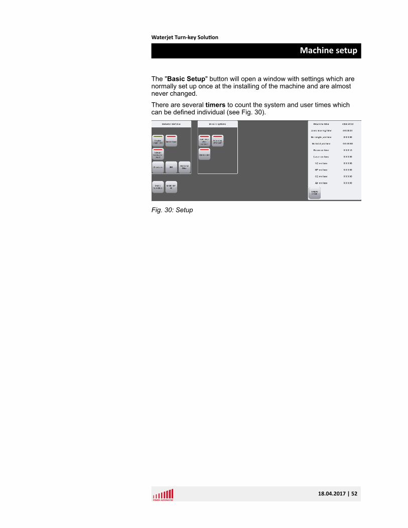
The "Basic Setup" button will open a window with settings which arenormally set up once at the installing of the machine and are almostnever changed.
There are several timers to count the system and user times whichcan be defined individual (see Fig. 30).
Fig. 30: Setup
Waterjet Turn-key Solution
Machine setup
18.04.2017 | 52
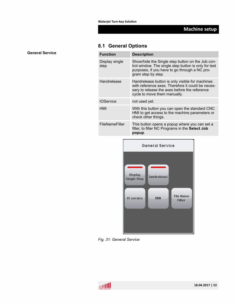
8.1 General OptionsFunction Description
Display singlestep
Show/hide the Single step button on the Job con-trol window. The single step button is only for testpurposes, if you have to go through a NC pro-gram step by step.
Handrelease Handrelease button is only visible for machineswith reference axes. Therefore it could be neces-sary to release the axes before the referencecycle to move them manually.
IOService not used yet.
HMI With this button you can open the standard CNCHMI to get access to the machine parameters orcheck other things.
FileNameFilter This button opens a popup where you can set afilter, to filter NC Programs in the Select Jobpopup.
Fig. 31: General Service
General Service
Waterjet Turn-key Solution
Machine setup
18.04.2017 | 53
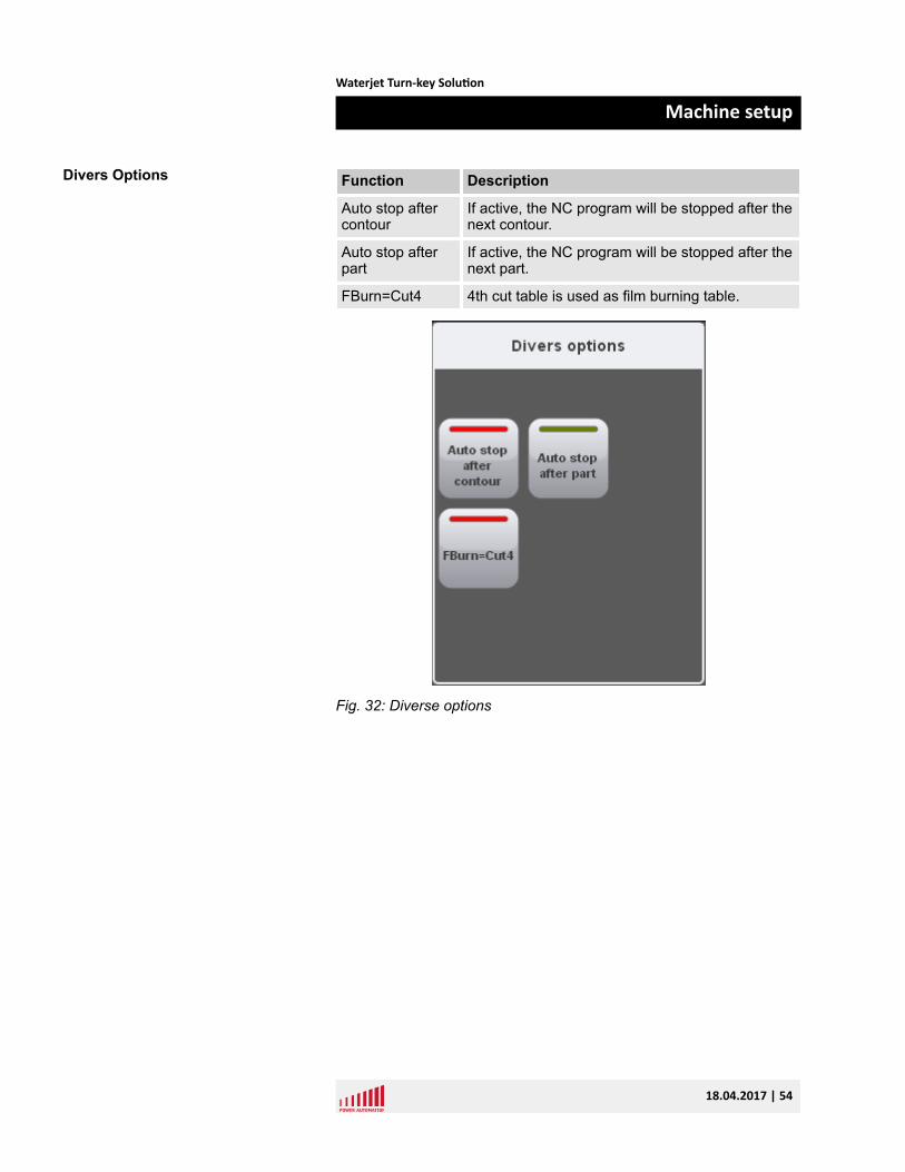
Function Description
Auto stop aftercontour
If active, the NC program will be stopped after thenext contour.
Auto stop afterpart
If active, the NC program will be stopped after thenext part.
FBurn=Cut4 4th cut table is used as film burning table.
Fig. 32: Diverse options
Divers Options
Waterjet Turn-key Solution
Machine setup
18.04.2017 | 54
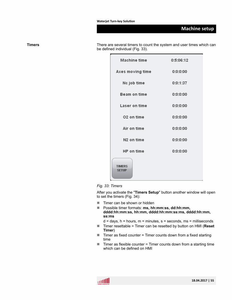
There are several timers to count the system and user times which canbe defined individual (Fig. 33).
Fig. 33: Timers
After you activate the "Timers Setup" button another window will opento set the timers (Fig. 34):
n Timer can be shown or hiddenn Possible timer formats: ms, hh:mm:ss, dd:hh:mm,
dddd:hh:mm:ss, hh:mm, dddd:hh:mm:ss:ms, dddd:hh:mm,ss:msd = days, h = hours, m = minutes, s = seconds, ms = milliseconds
n Timer resettable = Timer can be resetted by button on HMI (ResetTimer)
n Timer as fixed counter = Timer counts down from a fixed startingtime
n Timer as flexible counter = Timer counts down from a starting timewhich can be defined on HMI
Timers
Waterjet Turn-key Solution
Machine setup
18.04.2017 | 55
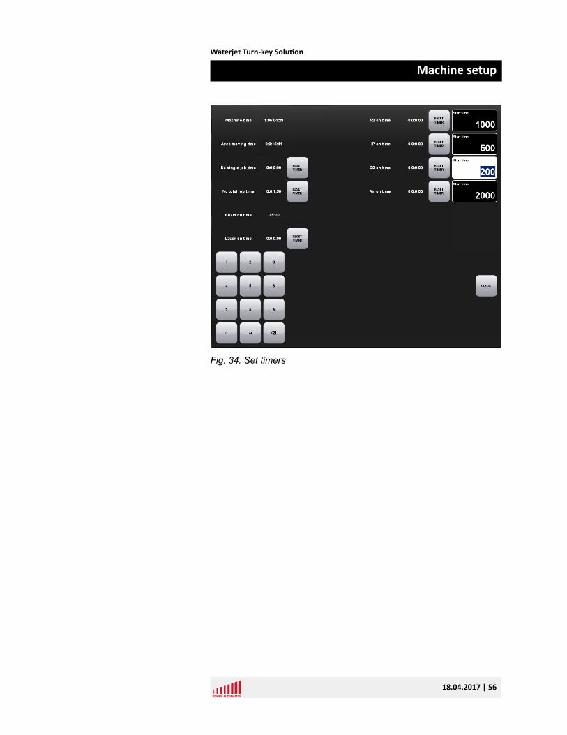
Fig. 34: Set timers
Waterjet Turn-key Solution
Machine setup
18.04.2017 | 56
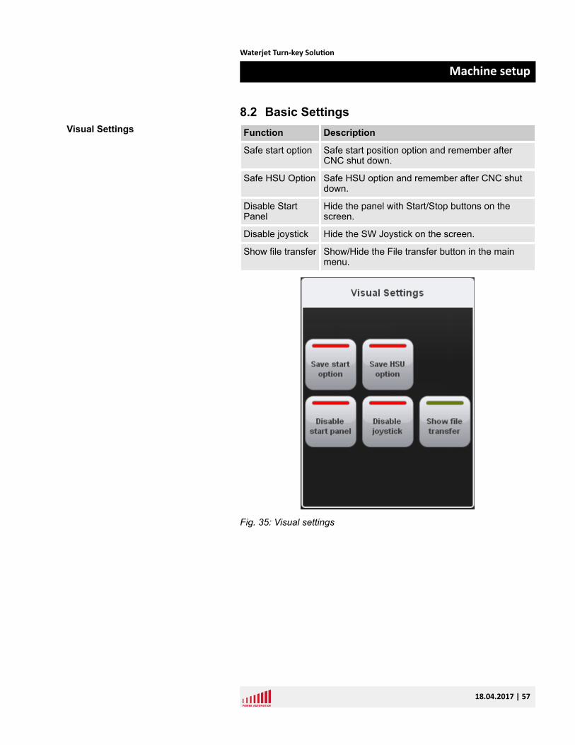
8.2 Basic SettingsFunction Description
Safe start option Safe start position option and remember afterCNC shut down.
Safe HSU Option Safe HSU option and remember after CNC shutdown.
Disable StartPanel
Hide the panel with Start/Stop buttons on thescreen.
Disable joystick Hide the SW Joystick on the screen.
Show file transfer Show/Hide the File transfer button in the mainmenu.
Fig. 35: Visual settings
Visual Settings
Waterjet Turn-key Solution
Machine setup
18.04.2017 | 57
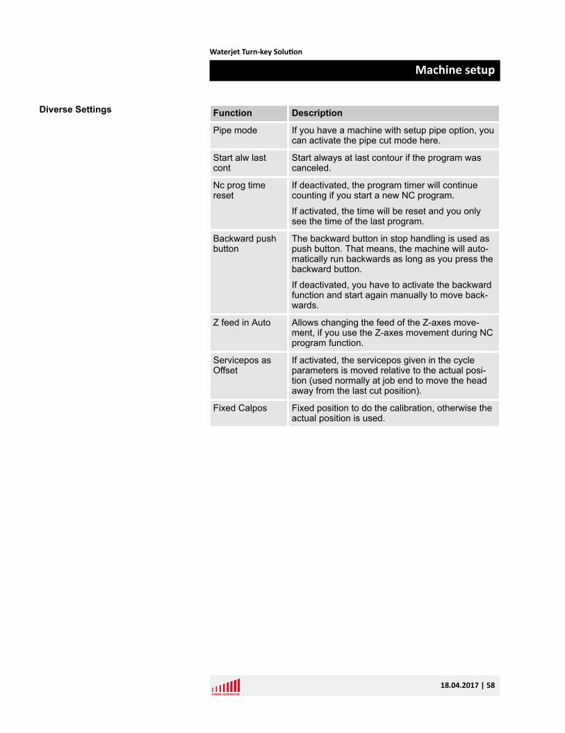
Function Description
Pipe mode If you have a machine with setup pipe option, youcan activate the pipe cut mode here.
Start alw lastcont
Start always at last contour if the program wascanceled.
Nc prog timereset
If deactivated, the program timer will continuecounting if you start a new NC program.
If activated, the time will be reset and you onlysee the time of the last program.
Backward pushbutton
The backward button in stop handling is used aspush button. That means, the machine will auto-matically run backwards as long as you press thebackward button.
If deactivated, you have to activate the backwardfunction and start again manually to move back-wards.
Z feed in Auto Allows changing the feed of the Z-axes move-ment, if you use the Z-axes movement during NCprogram function.
Servicepos asOffset
If activated, the servicepos given in the cycleparameters is moved relative to the actual posi-tion (used normally at job end to move the headaway from the last cut position).
Fixed Calpos Fixed position to do the calibration, otherwise theactual position is used.
Diverse Settings
Waterjet Turn-key Solution
Machine setup
18.04.2017 | 58
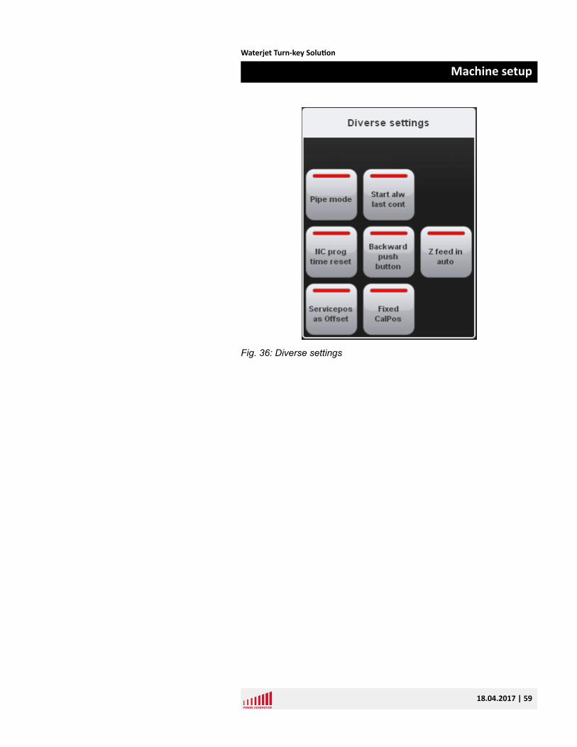
Fig. 36: Diverse settings
Waterjet Turn-key Solution
Machine setup
18.04.2017 | 59
Function Description
Use safetyretract
Use safety retract options if no C2C movementtype is set in database.
Large up Large movement of Z retract.
Small up Small movement of Z retract.
Dist for switch tolarge up
Below this distance the small retract is used, oth-erwise the large distance is used.
Fig. 37: Retract settings
Retract Settings
Waterjet Turn-key Solution
Machine setup
18.04.2017 | 60
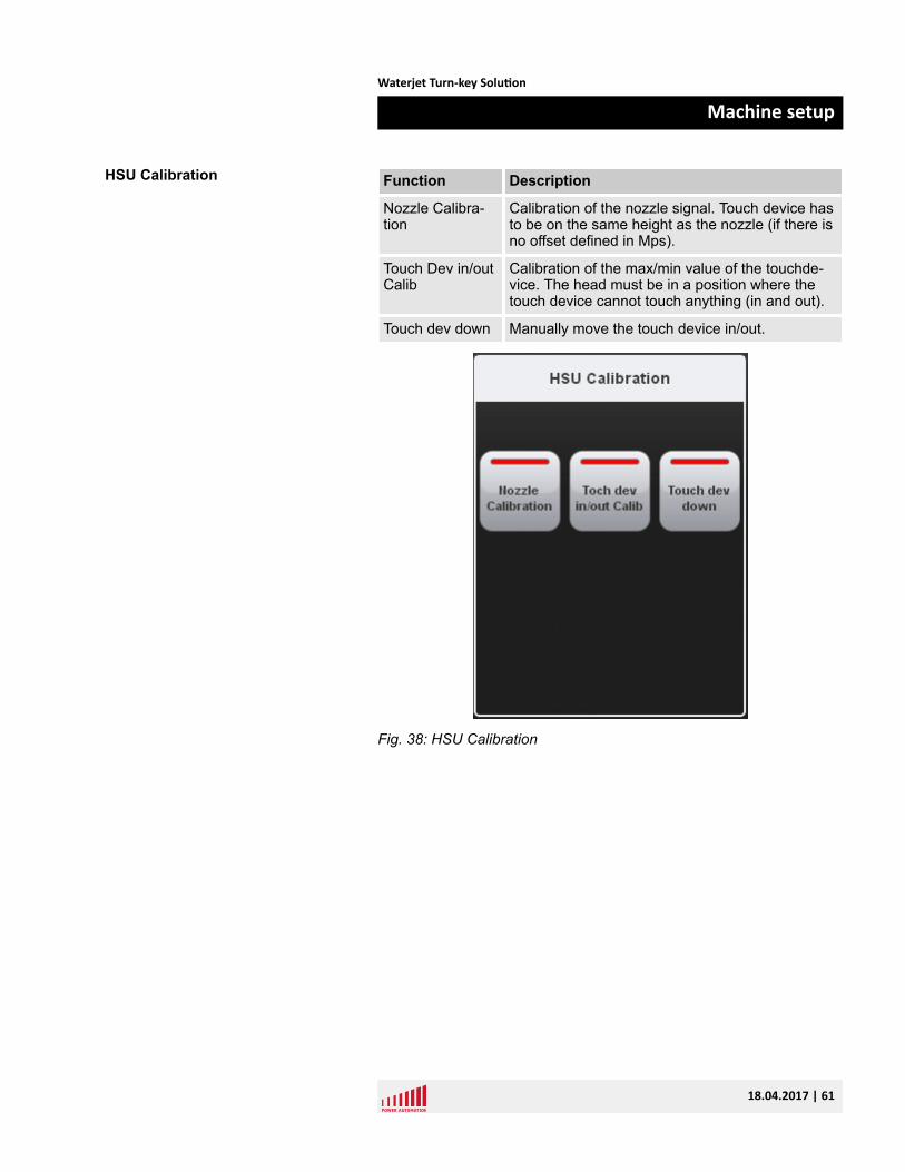
Function Description
Nozzle Calibra-tion
Calibration of the nozzle signal. Touch device hasto be on the same height as the nozzle (if there isno offset defined in Mps).
Touch Dev in/outCalib
Calibration of the max/min value of the touchde-vice. The head must be in a position where thetouch device cannot touch anything (in and out).
Touch dev down Manually move the touch device in/out.
Fig. 38: HSU Calibration
HSU Calibration
Waterjet Turn-key Solution
Machine setup
18.04.2017 | 61
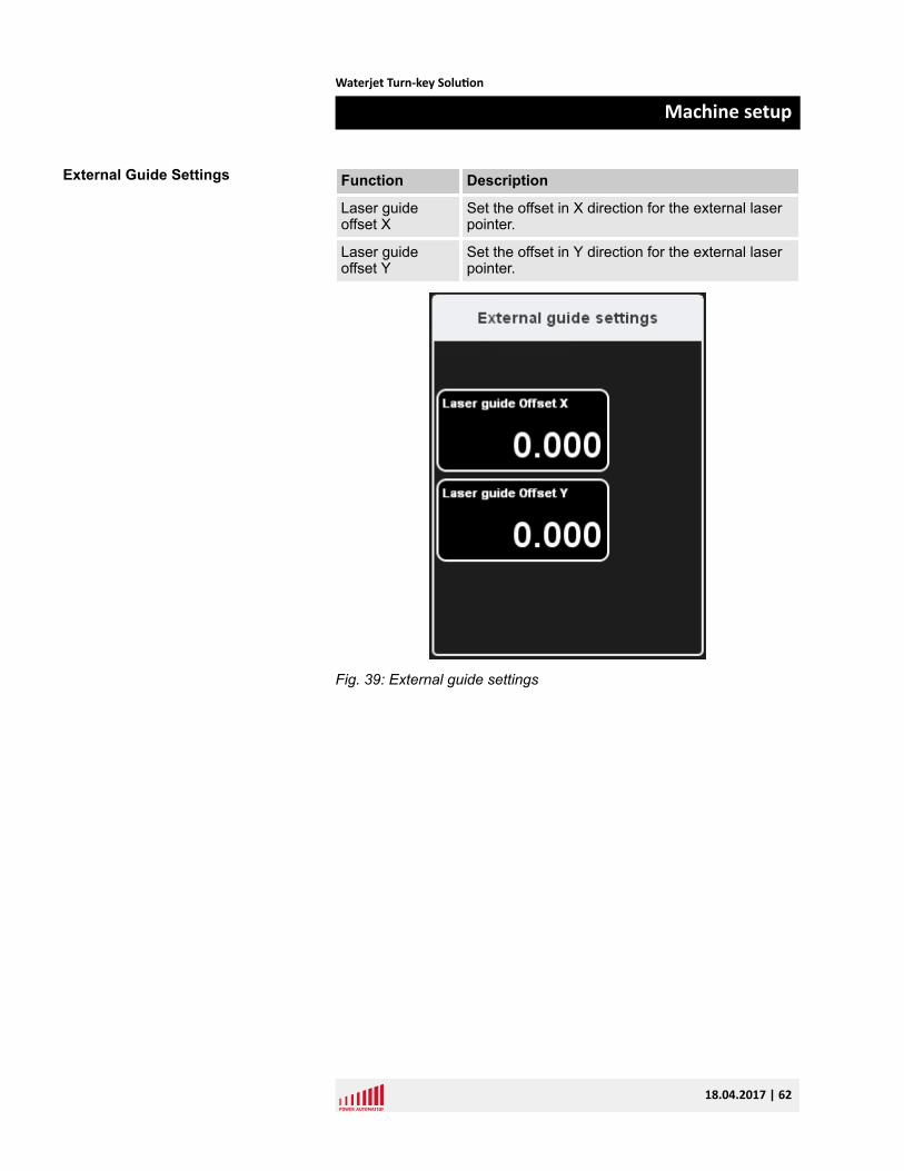
Function Description
Laser guideoffset X
Set the offset in X direction for the external laserpointer.
Laser guideoffset Y
Set the offset in Y direction for the external laserpointer.
Fig. 39: External guide settings
External Guide Settings
Waterjet Turn-key Solution
Machine setup
18.04.2017 | 62
9 Service and return process9.1 ServiceBy PhonePA's well-educated service staff is available to answer your technicalquestions. Due to the close co-operation with our customers, our engi-neers can solve problems often immediately by phone.
If on-site support is necessary, our service staff will diagnose theproblem and will prepare our field service engineer beforehand. This isto make on-site service as much effective as possible.
By Remote Control SoftwareEvery PA CNC is equipped with an Ethernet interface. If you have anetwork on-site, you only have to integrate the CNC system to yournetwork for world-wide-web access.
Power Automation provides a remote control software which allows ourservice staff to log into your CNC. This provides all the informationavailable on the machine. They can check all the data like the PLCprogram, machine parameters, or the NC programs directly on the realsystem under real conditions. This is the fastest and most cost-effec-tive way to solve problems.
On-SiteIf necessary our service engineers will visit you to help you solve yourproblems on-site. Our engineers are trained continuously to be alwaysup to date. Thereby you always can expect the best support.
Due to our service centers worldwide, our service staff can be on sitenormally within 24 hours at the latest.
Service At Power Automation
Waterjet Turn-key Solution
Service and return process
18.04.2017 | 63
9.1.1 Service addresses
Power Automation GmbH (Headquarters)Gottlieb-Daimler-Strasse 17/2
D-74385 Pleidelsheim
Tel: +49-7144-899-0
Fax: +49-7144-899-299
Power Automation America, Inc.8601 Jameel Road, Suite 140
Houston, Texas 77040 USA
Tel: +1-713-263-9400
Fax: +1-281-715-2500
Power Automation Office TurkeyKustepe Mah. Mecidiyekoy Yolu Cad.
Trump Towers No. 12 Kule: 2 K:18
Daire no: 3211022839 Sisli / Istanbul
Turkey
Tel: +90-212-306-3280
Fax: +90-212-306-3101
Shenzhen Double CNC Tech Co., Ltd8th Floor,WeiXinDa Building
Bao Min Road 2
Xi Xiang Town
Bao'an District, Shenzhen, Guangdong
PR China
Service Addresses
Waterjet Turn-key Solution
Service and return process
18.04.2017 | 64
Power Automation France SARLCité de la Photonique
Bâtiment Pléione
11 avenue Canteranne
33600 Pessac
France
Tel: +33-559-4010-50
Fax: +33-559-4010-59
ACE AutomationA-721, Twinrex B/D
Deokpungdong-ro 111-10, Hanam-si
Gyeonggi-do, 465-831
South Korea
9.2 Spare partsDue to the high quality of our products we can assure you that you willnot need this service often. Spare parts are often urgent so PowerAutomation provides the relevant spare parts at the local service cen-ters for immediate dispatch.
Our 3 service centers in Europe, North America and Asia allow us todeliver all needed parts typically within 24 hours.
Only trust PA's original parts - because every part passes our tightquality checks.
We also offer consulting services to identify the most critical parts forthe machines in your production facilities. We suggest what criticalstock may be required to ensure a minimum downtime of yourmachines. Our specialists look for common parts to keep your inven-tory levels at a minimum.
Spare Parts
Waterjet Turn-key Solution
Service and return process
18.04.2017 | 65
9.3 Return policy and procedure
Power Automation will only accept control units and components forreplacement or repair, if they have been returned in adherence to theprovisions given below.
n If material warranty is void or if no error is detected, a testing flatrate will be charged. If an error is determined, the testing flat ratewill be charged to the repair costs.
n If material warranty is void you will receive a repair offer.n Before the repair starts we need a repair order from you, if the
material warranty is extinguished.
1. Contact Power Automation to receive an RMA form in Excelformat. Ä “RMA Form” on page 67
2. Open the 'RMA Process' form provided by Power Automation.
Use one form for each single part you want to ship back toPower Automation.
3. Fill in the form.
The fields marked with a red star (*) are mandatory fields.
Only fill in the fields next to the yellow bar on the left side of theform.
Do not fill in the fields next to the blue bar on the left side of theform. These fields are for internal notes only and blocked.
4. Send the completed form as an Excel file by email [email protected] to your local support (see web-page).
ð We will check the data and send the form back to you as aPDF file including an RMA number or tell you what informa-tion is missing if necessary.
5. Print the RMA form and add it to the accompanying componentsand documents.
6. After the check and repair the components will be shipped to youimmediately.
Policy
Acquiring RMA Number
Waterjet Turn-key Solution
Service and return process
18.04.2017 | 66
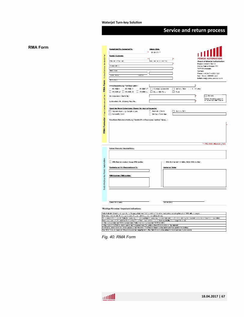
Fig. 40: RMA Form
RMA Form
Waterjet Turn-key Solution
Service and return process
18.04.2017 | 67
1. Pack the goods properly.
Controls must be packed in original or equivalent packaging. Ifthe packaging is not proper, Power Automation will charge apackaging flat rate.
NOTICE! Damages due to inadequate packaging Inadequatepackaging may result in damages to the control unit. Thiswill void the material warranty. PA does not bear any liabili-ties for damages in transit.
2. Write the RMA number on the cardboard box clearly readablefrom outside.
The incoming goods department rejects all deliverieswithout a visible, valid RMA number.
3. Ship the goods FREE DOMICILE / DDU. Other deliveries will berejected.
The goods have to arrive within 4 weeks after the date of theapproved RMA form.
9.4 TrainingHaving the best CNCs is one thing, to bring out the best of it is theother.
The PA training program comprises of a number of individually combin-able training modules which offer you a well-founded knowledge forusing PA CNCs. At our training centers we bring your employees -beginners and experts- up to scratch in CNC technology. We also offerindividual training courses at your site. The contents of the courses willbe customized to your requirements.
For more information see Ä Chapter 9.1.1 “Service addresses”on page 64.
Return
Conditions Of Supply
Training Courses
Waterjet Turn-key Solution
Service and return process
18.04.2017 | 68
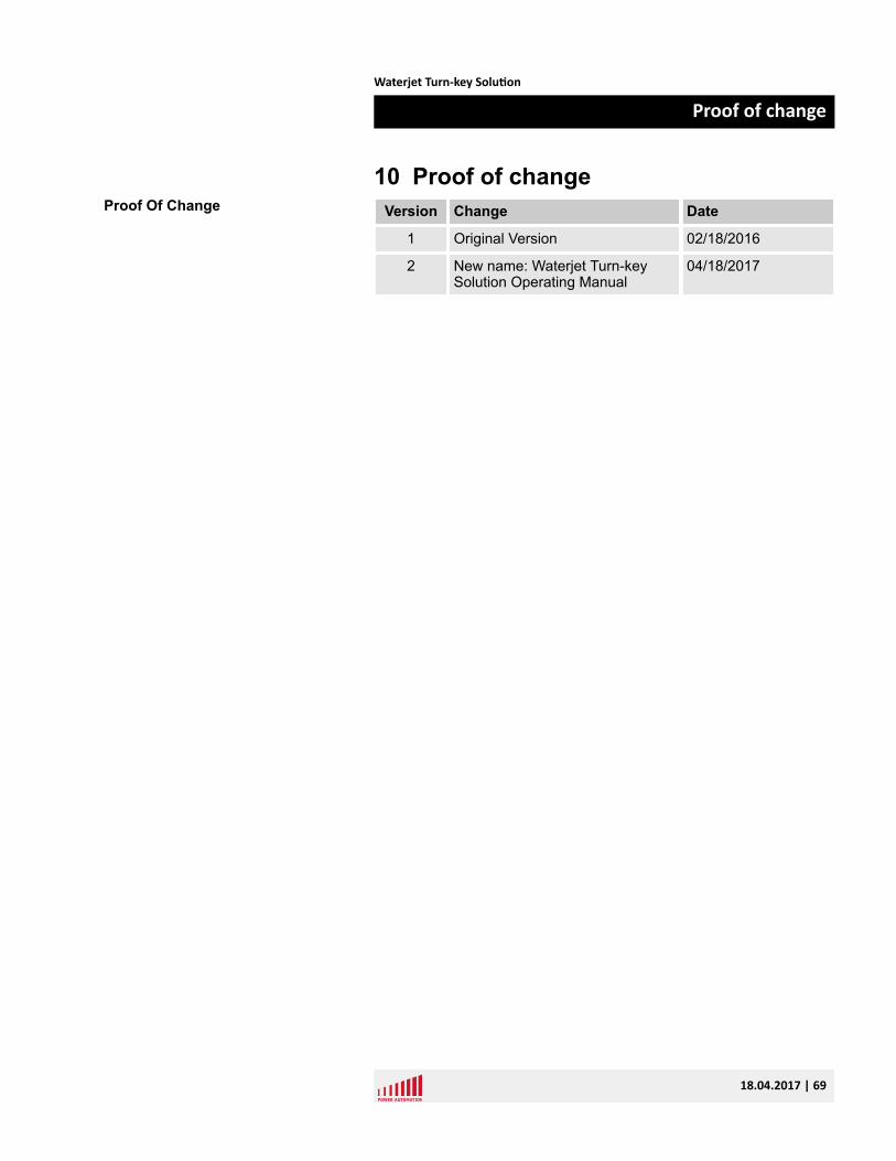
10 Proof of changeVersion Change Date
1 Original Version 02/18/2016
2 New name: Waterjet Turn-keySolution Operating Manual
04/18/2017
Proof Of Change
Waterjet Turn-key Solution
Proof of change
18.04.2017 | 69

Waterjet Turn-key Solution
Proof of change
18.04.2017 | 70
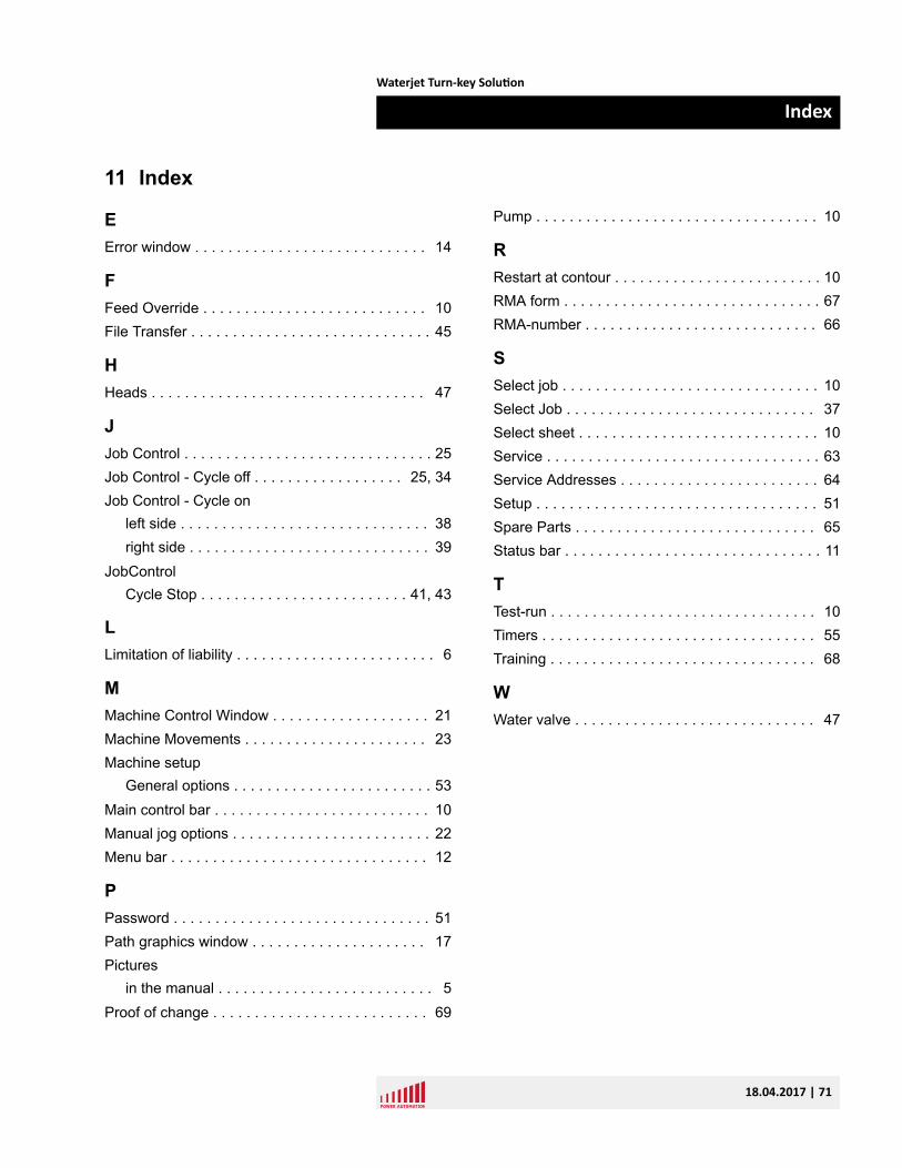
11 Index
EError window . . . . . . . . . . . . . . . . . . . . . . . . . . . . 14
FFeed Override . . . . . . . . . . . . . . . . . . . . . . . . . . . 10File Transfer . . . . . . . . . . . . . . . . . . . . . . . . . . . . . 45
HHeads . . . . . . . . . . . . . . . . . . . . . . . . . . . . . . . . . 47
JJob Control . . . . . . . . . . . . . . . . . . . . . . . . . . . . . . 25Job Control - Cycle off . . . . . . . . . . . . . . . . . . 25, 34Job Control - Cycle on
left side . . . . . . . . . . . . . . . . . . . . . . . . . . . . . . 38right side . . . . . . . . . . . . . . . . . . . . . . . . . . . . . 39
JobControlCycle Stop . . . . . . . . . . . . . . . . . . . . . . . . . 41, 43
LLimitation of liability . . . . . . . . . . . . . . . . . . . . . . . . 6
MMachine Control Window . . . . . . . . . . . . . . . . . . . 21Machine Movements . . . . . . . . . . . . . . . . . . . . . . 23Machine setup
General options . . . . . . . . . . . . . . . . . . . . . . . . 53Main control bar . . . . . . . . . . . . . . . . . . . . . . . . . . 10Manual jog options . . . . . . . . . . . . . . . . . . . . . . . . 22Menu bar . . . . . . . . . . . . . . . . . . . . . . . . . . . . . . . 12
PPassword . . . . . . . . . . . . . . . . . . . . . . . . . . . . . . . 51Path graphics window . . . . . . . . . . . . . . . . . . . . . 17Pictures
in the manual . . . . . . . . . . . . . . . . . . . . . . . . . . 5Proof of change . . . . . . . . . . . . . . . . . . . . . . . . . . 69
Pump . . . . . . . . . . . . . . . . . . . . . . . . . . . . . . . . . . 10
RRestart at contour . . . . . . . . . . . . . . . . . . . . . . . . . 10RMA form . . . . . . . . . . . . . . . . . . . . . . . . . . . . . . . 67RMA-number . . . . . . . . . . . . . . . . . . . . . . . . . . . . 66
SSelect job . . . . . . . . . . . . . . . . . . . . . . . . . . . . . . . 10Select Job . . . . . . . . . . . . . . . . . . . . . . . . . . . . . . 37Select sheet . . . . . . . . . . . . . . . . . . . . . . . . . . . . . 10Service . . . . . . . . . . . . . . . . . . . . . . . . . . . . . . . . . 63Service Addresses . . . . . . . . . . . . . . . . . . . . . . . . 64Setup . . . . . . . . . . . . . . . . . . . . . . . . . . . . . . . . . . 51Spare Parts . . . . . . . . . . . . . . . . . . . . . . . . . . . . . 65Status bar . . . . . . . . . . . . . . . . . . . . . . . . . . . . . . . 11
TTest-run . . . . . . . . . . . . . . . . . . . . . . . . . . . . . . . . 10Timers . . . . . . . . . . . . . . . . . . . . . . . . . . . . . . . . . 55Training . . . . . . . . . . . . . . . . . . . . . . . . . . . . . . . . 68
WWater valve . . . . . . . . . . . . . . . . . . . . . . . . . . . . . 47
Waterjet Turn-key Solution
Index
18.04.2017 | 71