Embed Size (px)
Citation preview

© 2008 Cummins Inc., Box 3005, Columbus, IN 47202-3005 U.S.A. Printed from QuickServe® Online.All Rights Reserved. Last Modified: 06-Nov-2013
File: 06-t05-2215cl Page 1 of 16
FAULT CODE 2215 (ISC/QSC/ISL/QSL Automotive, Industrial, or MarineApplication) - Fuel Pump Delivery Pressure Low - Data Valid But Below Normal
Operating Range - Moderately Severe LevelTROUBLESHOOTING SUMMARY
STEPS SPECIFICATIONS SRT CODESTEP 1: Check the fault codes.
STEP 1A: Read the fault codes. Fault Code 275, 449, 1117, or2311 active or high inactivecounts?
STEP 1B: Inspect for external fuel leaks. Fuel leaks present?STEP 1C: Verify the rail fuel pressure
sensor accuracy.Fuel rail pressure +/- 43 bar [+/-624 psi]?
STEP 2: Check engine operation.STEP 2A: Attempt to start the engine. Engine start?STEP 2B: Check the fuel supply. Adequate amount of fuel in the
tank?
STEP 3: Check the low-pressure fuel system. (Engine not operating)STEP 3A: Check the fuel lift pump
pressure.Fuel lift pump pressure withinspecifications?
STEP 3B: Measure the fuel gear pumppressure.
Fuel gear pump pressure greaterthan specifications?
STEP 4: Check the low-pressure fuel system. (Engine operating)STEP 4A: Check for external fuel leak. Any external fuel leaks?STEP 4B: Check for air in the high-
pressure pump fuel supply.Air present in the fuel supply?
STEP 4C: Measure inlet restriction at theoriginal equipmentmanufacturer (OEM) connectionpoint.
OEM inlet restriction abovespecification?
STEP 4D: Measure inlet restriction at thegear pump inlet.
Gear pump inlet restrictionabove specification?
STEP 4E: Measure the gear pumppressure.
Gear pump pressure abovespecification?
STEP 4F: Measure the fuel filterrestriction.
Fuel filter pressure drop abovespecification?
STEP 5: Check the high-pressure fuel system.STEP 5A: Measure the fuel pump head
flow.Fuel pump head flow greaterthan 100 cc [3.4 oz] in 30seconds of cranking?
STEP 5B: Check for excessive fuel returnfrom the fuel injector drain line.
Fuel injector leakage excessive?
STEP 5C: Check for excessive fuel returnfrom the high-pressure pump.
Fuel pump leakage excessive?
STEP 5D: Check for excessive leakagefrom the rail fuel pressure reliefvalve.
Rail fuel pressure relief valveleaking more than 30 drops perminute?

© 2008 Cummins Inc., Box 3005, Columbus, IN 47202-3005 U.S.A. Printed from QuickServe® Online.All Rights Reserved. Last Modified: 06-Nov-2013
File: 06-t05-2215cl Page 2 of 16
STEP 6: Verify the repair is complete.STEP 6A: Disable the fault code. Fault Code 2215 becomes active
during loaded engine operation?STEP 6B: Clear the inactive fault codes. All fault codes cleared?
TROUBLESHOOTING STEP
STEP 1: Check the fault codes.STEP 1A: Read the fault codes.
Condition:• Turn keyswitch ON.• Connect INSITE™ electronic service tool.
Action Specification/Repair Next Step
Read the fault codes.• Use INSITE™ electronic service tool to read
the fault codes.
Fault Code 275, 449, 1117, or 2311 active orhigh inactive counts?YES
Appropriatetroubleshooting tree
Fault Code 275, 449, 1117, or 2311 is activeor high inactive counts?NO
1B
STEP 1B: Inspect for external fuel leaks.
Condition:• Turn keyswitch OFF.
Action Specification/Repair Next Step
Check for external fuel leaks.• Look for fuel leaking from loose fuel fittings
and damaged fuel lines, or damagedcomponents.
Fuel leaks present?YESRepair:Repair the fuel leak.• Use the procedure in the ISC, ISCe,
QSC8.3, ISL, ISLe3, ISLe4 and QSL9Troubleshooting and Repair Manual,Bulletin 4021418: Refer to Procedure006-024 in Section 6.
6A
Fuel leaks present?NO
1C
© 2008 Cummins Inc., Box 3005, Columbus, IN 47202-3005 U.S.A. Printed from QuickServe® Online.All Rights Reserved. Last Modified: 06-Nov-2013
File: 06-t05-2215cl Page 3 of 16
STEP 1C: Verify the rail fuel pressure sensor accuracy.
Condition:• Turn keyswtich ON.• Connect INSITE™ electronic service tool.• Monitor INSITE™ electronic service tool.• Do not operate the engine.
Action Specification/Repair Next Step
Make sure the correct sensor part number isinstalled in the high pressure fuel rail.Monitor the fuel rail pressure.• Use INSITE™ electronic service tool to
measure fuel rail pressure.
Fuel rail pressure 0 +/- 43 bar [0 +/- 624 psi]?YES
2A
Fuel rail pressure 0 +/- 43 bar [0 +/- 624 psi]?NORepair:Replace the rail fuel pressure sensor.• Refer to Procedure 019-115 in Section 19.
6A
STEP 2: Check engine operation.STEP 2A: Check to see if the engine will start.
Condition:• Turn keyswitch ON.
Action Specification/Repair Next Step
Attempt to start the engine. Engine start?YES
4A
Engine start?NO
2B
STEP 2B: Check the fuel supply.
Condition:• Turn keyswitch OFF.
Action Specification/Repair Next Step
Check the fuel tank for fuel. Adequate amount of fuel in the tank?YES
3A
Adequate amount of fuel in the tank?NORepair:Fill the tank with fuel.
6A
© 2008 Cummins Inc., Box 3005, Columbus, IN 47202-3005 U.S.A. Printed from QuickServe® Online.All Rights Reserved. Last Modified: 06-Nov-2013
File: 06-t05-2215cl Page 4 of 16
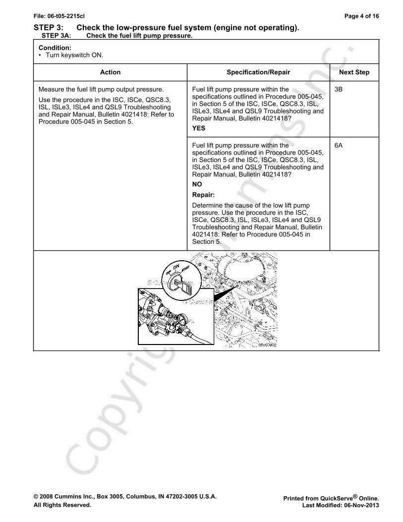
STEP 3: Check the low-pressure fuel system (engine not operating).STEP 3A: Check the fuel lift pump pressure.
Condition:• Turn keyswitch ON.
Action Specification/Repair Next Step
Measure the fuel lift pump output pressure.Use the procedure in the ISC, ISCe, QSC8.3,ISL, ISLe3, ISLe4 and QSL9 Troubleshootingand Repair Manual, Bulletin 4021418: Refer toProcedure 005-045 in Section 5.
Fuel lift pump pressure within thespecifications outlined in Procedure 005-045,in Section 5 of the ISC, ISCe, QSC8.3, ISL,ISLe3, ISLe4 and QSL9 Troubleshooting andRepair Manual, Bulletin 4021418?YES
3B
Fuel lift pump pressure within thespecifications outlined in Procedure 005-045,in Section 5 of the ISC, ISCe, QSC8.3, ISL,ISLe3, ISLe4 and QSL9 Troubleshooting andRepair Manual, Bulletin 4021418?NORepair:Determine the cause of the low lift pumppressure. Use the procedure in the ISC,ISCe, QSC8.3, ISL, ISLe3, ISLe4 and QSL9Troubleshooting and Repair Manual, Bulletin4021418: Refer to Procedure 005-045 inSection 5.
6A

© 2008 Cummins Inc., Box 3005, Columbus, IN 47202-3005 U.S.A. Printed from QuickServe® Online.All Rights Reserved. Last Modified: 06-Nov-2013
File: 06-t05-2215cl Page 5 of 16
STEP 3B: Measure fuel gear pump pressure.
Condition:• Turn keyswitch ON.
Action Specification/Repair Next Step
Measure the gear pump pressure duringcranking.Use the procedure in the ISC, ISCe, QSC8.3,ISL, ISLe3, ISLe4 and QSL9 Troubleshootingand Repair Manual, Bulletin 4021418: Refer toProcedure 005-025 in Section 5.
Fuel gear pump pressure greater than thespecifications outlined in Procedure 005-025,in Section 5 of the ISC, ISCe, QSC8.3, ISL,ISLe3, ISLe4 and QSL9 Troubleshooting andRepair Manual, Bulletin 4021418?YES
5A
Fuel gear pump pressure greater than thespecifications outlined in Procedure 005-025,in Section 5 of the ISC, ISCe, QSC8.3, ISL,ISLe3, ISLe4 and QSL9 Troubleshooting andRepair Manual, Bulletin 4021418?NORepair:Replace the fuel gear pump module.Use the procedure in the ISC, ISCe, QSC8.3,ISL, ISLe3, ISLe4 and QSL9 Troubleshootingand Repair Manual, Bulletin 4021418: Referto Procedure 005-025 in Section 5.
6A
© 2008 Cummins Inc., Box 3005, Columbus, IN 47202-3005 U.S.A. Printed from QuickServe® Online.All Rights Reserved. Last Modified: 06-Nov-2013
File: 06-t05-2215cl Page 6 of 16
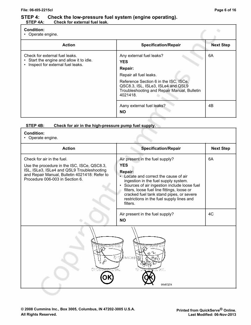
STEP 4: Check the low-pressure fuel system (engine operating).STEP 4A: Check for external fuel leak.
Condition:• Operate engine.
Action Specification/Repair Next Step
Check for external fuel leaks.• Start the engine and allow it to idle.• Inspect for external fuel leaks.
Any external fuel leaks?YESRepair:Repair all fuel leaks.Reference Section 6 in the ISC, ISCe,QSC8.3, ISL, ISLe3, ISLe4 and QSL9Troubleshooting and Repair Manual, Bulletin4021418.
6A
Aany external fuel leaks?NO
4B
STEP 4B: Check for air in the high-pressure pump fuel supply.
Condition:• Operate engine.
Action Specification/Repair Next Step
Check for air in the fuel.Use the procedure in the ISC, ISCe, QSC8.3,ISL, ISLe3, ISLe4 and QSL9 Troubleshootingand Repair Manual, Bulletin 4021418: Refer toProcedure 006-003 in Section 6.
Air present in the fuel supply?YESRepair:• Locate and correct the cause of air
ingestion in the fuel supply system.• Sources of air ingestion include loose fuel
filters, loose fuel line fittings, loose orcracked fuel tank stand pipes, or severerestrictions in the fuel supply lines andfilters.
6A
Air present in the fuel supply?NO
4C

© 2008 Cummins Inc., Box 3005, Columbus, IN 47202-3005 U.S.A. Printed from QuickServe® Online.All Rights Reserved. Last Modified: 06-Nov-2013
File: 06-t05-2215cl Page 7 of 16
STEP 4C: Measure the inlet restriction at the OEM connection point.
Condition:• Operate engine.
Action Specification/Repair Next Step
Measure the fuel inlet restriction.• Use the procedure in the ISC, ISCe, QSC8.3,
ISL, ISLe3, ISLe4 and QSL9 Troubleshootingand Repair Manual, Bulletin 4021418: Refer toProcedure 006-020 in Section 6.
If the engine will not start or the engine startsand stalls, be sure fuel is primed to the gearpump. This test is only valid if the engine isoperating.
OEM inlet restriction above specificationoutlined in the ISC, ISCe, QSC8.3, ISL,ISLe3, ISLe4 and QSL9 Troubleshooting andRepair Manual, Bulletin 4021418? Refer toProcedure 006-020 in Section 6.YESRepair:A fuel restriction exists upstream of the OEMconnection point. Refer to the OEM servicemanual.
6A
OEM inlet restriction above specificationoutlined in the ISC, ISCe, QSC8.3, ISL,ISLe3, ISLe4 and QSL9 Troubleshooting andRepair Manual, Bulletin 4021418? Refer toProcedure 006-020 in Section 6.NO
4D
© 2008 Cummins Inc., Box 3005, Columbus, IN 47202-3005 U.S.A. Printed from QuickServe® Online.All Rights Reserved. Last Modified: 06-Nov-2013
File: 06-t05-2215cl Page 8 of 16
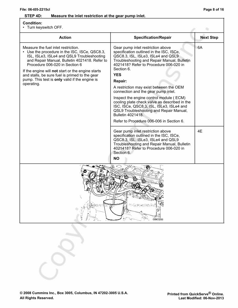
STEP 4D: Measure the inlet restriction at the gear pump inlet.
Condition:• Turn keyswitch OFF.
Action Specification/Repair Next Step
Measure the fuel inlet restriction.• Use the procedure in the ISC, ISCe, QSC8.3,
ISL, ISLe3, ISLe4 and QSL9 Troubleshootingand Repair Manual, Bulletin 4021418. Refer toProcedure 006-020 in Section 6
If the engine will not start or the engine startsand stalls, be sure fuel is primed to the gearpump. This test is only valid if the engine isoperating.
Gear pump inlet restriction abovespecification outlined in the ISC, ISCe,QSC8.3, ISL, ISLe3, ISLe4 and QSL9Troubleshooting and Repair Manual, Bulletin4021418? Refer to Procedure 006-020 inSection 6.YESRepair:A restriction may exist between the OEMconnection and the gear pump inlet.Inspect the engine control module ( ECM)cooling plate check valve as described in theISC, ISCe, QSC8.3, ISL, ISLe3, ISLe4 andQSL9 Troubleshooting and Repair Manual,Bulletin 4021418.Refer to Procedure 006-006 in Section 6.
6A
Gear pump inlet restriction abovespecification outlined in the ISC, ISCe,QSC8.3, ISL, ISLe3, ISLe4 and QSL9Troubleshooting and Repair Manual, Bulletin4021418? Refer to Procedure 006-020 inSection 6.NO
4E
© 2008 Cummins Inc., Box 3005, Columbus, IN 47202-3005 U.S.A. Printed from QuickServe® Online.All Rights Reserved. Last Modified: 06-Nov-2013
File: 06-t05-2215cl Page 9 of 16
STEP 4E: Measure the gear pump pressure.
Condition:• Turn keyswitch OFF.
Action Specification/Repair Next Step
Measure the gear pump pressure.• Use the Initial Check procedure in the ISC,
ISCe, QSC8.3, ISL, ISLe3, ISLe4 and QSL9Troubleshooting and Repair Manual, Bulletin4021418. Refer to Procedure 005-025 inSection 5.
Gear pump pressure above specificationoutlined in the ISC, ISCe, QSC8.3, ISL,ISLe3, ISLe4 and QSL9 Troubleshooting andRepair Manual, Bulletin 4021418? Refer toProcedure 005-025 in Section 5.YES
4F
Gear pump pressure above specificationoutlined in the ISC, ISCe, QSC8.3, ISL,ISLe3, ISLe4 and QSL9 Troubleshooting andRepair Manual, Bulletin 4021418? Refer toProcedure 005-025 in Section 5.NORepair:The gear pump pressure is low.The gearpump is worn.Replace the gear pump. Use the procedurein the ISC, ISCe, QSC8.3, ISL, ISLe3, ISLe4and QSL9 Troubleshooting and RepairManual, Bulletin 402141.Refer to Procedure 005-025 in Section 5.
6A

© 2008 Cummins Inc., Box 3005, Columbus, IN 47202-3005 U.S.A. Printed from QuickServe® Online.All Rights Reserved. Last Modified: 06-Nov-2013
File: 06-t05-2215cl Page 10 of 16
STEP 4F: Measure the fuel filter restriction.
Condition:• Turn keyswitch ON.
Action Specification/Repair Next Step
Measure the pressure at the inlet to thepressure-side fuel filter.• Use the procedure in the ISC, ISCe, QSC8.3,
ISL, ISLe3, ISLe4 and QSL9 Troubleshootingand Repair Manual, Bulletin 4021418. Refer toProcedure 006-015 in Section 6.
Measure the pressure at the outlet of thepressure-side fuel filter.• Use the procedure in the ISC, ISCe, QSC8.3,
ISL, ISLe3, ISLe4 and QSL9 Troubleshootingand Repair Manual, Bulletin 4021418.
Refer to Procedure 006-015 in Section 6.
Fuel filter pressure drop abovespecification.?YESRepair:The fuel filter is plugged.Replace the pressure-side fuel filter. Use theprocedure in the ISC, ISCe, QSC8.3, ISL,ISLe3, ISLe4 and QSL9 Troubleshooting andRepair Manual, Bulletin 4021418.Refer to Procedure 006-015 in Section 6.
6A
Fuel filter pressure drop abovespecification.?NO
5A
© 2008 Cummins Inc., Box 3005, Columbus, IN 47202-3005 U.S.A. Printed from QuickServe® Online.All Rights Reserved. Last Modified: 06-Nov-2013
File: 06-t05-2215cl Page 11 of 16
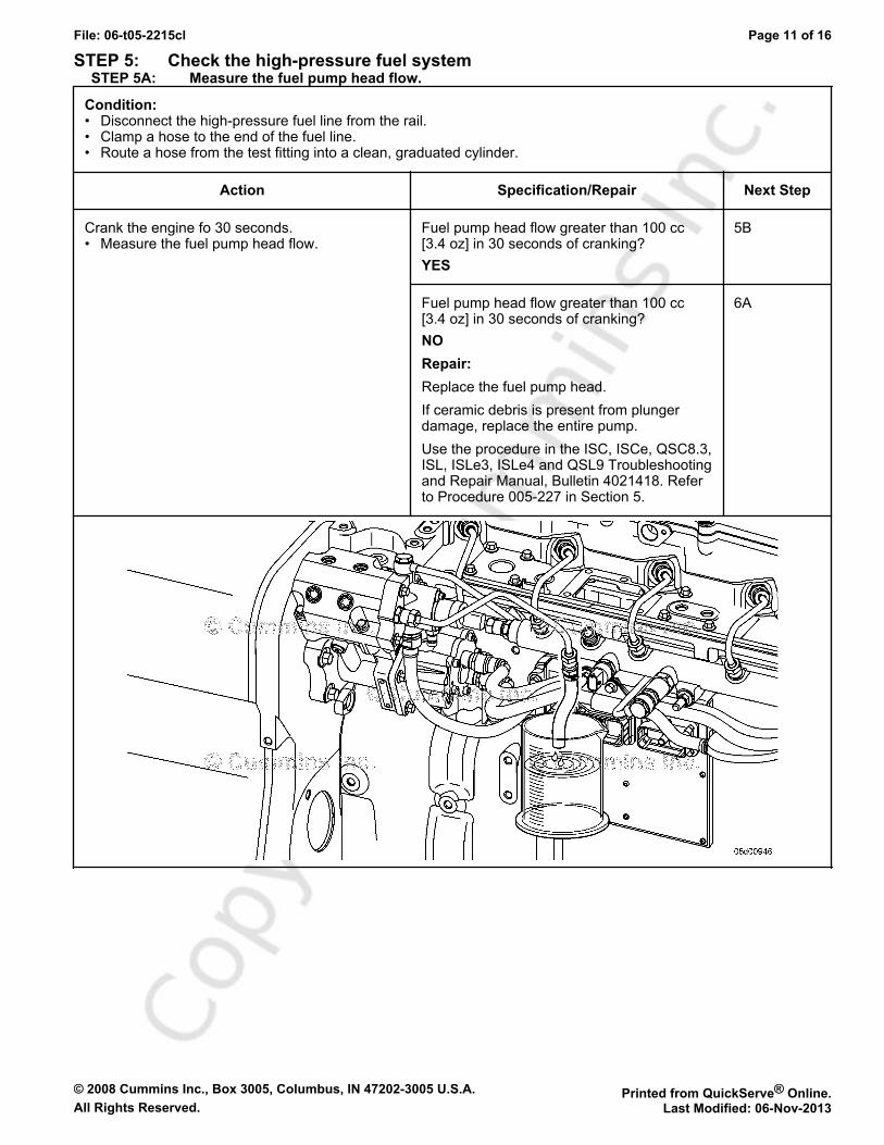
STEP 5: Check the high-pressure fuel systemSTEP 5A: Measure the fuel pump head flow.
Condition:• Disconnect the high-pressure fuel line from the rail.• Clamp a hose to the end of the fuel line.• Route a hose from the test fitting into a clean, graduated cylinder.
Action Specification/Repair Next Step
Crank the engine fo 30 seconds.• Measure the fuel pump head flow.
Fuel pump head flow greater than 100 cc[3.4 oz] in 30 seconds of cranking?YES
5B
Fuel pump head flow greater than 100 cc[3.4 oz] in 30 seconds of cranking?NORepair:Replace the fuel pump head.If ceramic debris is present from plungerdamage, replace the entire pump.Use the procedure in the ISC, ISCe, QSC8.3,ISL, ISLe3, ISLe4 and QSL9 Troubleshootingand Repair Manual, Bulletin 4021418. Referto Procedure 005-227 in Section 5.
6A
© 2008 Cummins Inc., Box 3005, Columbus, IN 47202-3005 U.S.A. Printed from QuickServe® Online.All Rights Reserved. Last Modified: 06-Nov-2013
File: 06-t05-2215cl Page 12 of 16
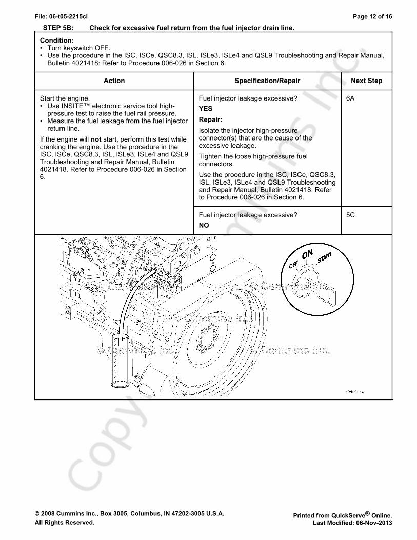
STEP 5B: Check for excessive fuel return from the fuel injector drain line.
Condition:• Turn keyswitch OFF.• Use the procedure in the ISC, ISCe, QSC8.3, ISL, ISLe3, ISLe4 and QSL9 Troubleshooting and Repair Manual,
Bulletin 4021418: Refer to Procedure 006-026 in Section 6.
Action Specification/Repair Next Step
Start the engine.• Use INSITE™ electronic service tool high-
pressure test to raise the fuel rail pressure.• Measure the fuel leakage from the fuel injector
return line.If the engine will not start, perform this test whilecranking the engine. Use the procedure in theISC, ISCe, QSC8.3, ISL, ISLe3, ISLe4 and QSL9Troubleshooting and Repair Manual, Bulletin4021418. Refer to Procedure 006-026 in Section6.
Fuel injector leakage excessive?YESRepair:Isolate the injector high-pressureconnector(s) that are the cause of theexcessive leakage.Tighten the loose high-pressure fuelconnectors.Use the procedure in the ISC, ISCe, QSC8.3,ISL, ISLe3, ISLe4 and QSL9 Troubleshootingand Repair Manual, Bulletin 4021418. Referto Procedure 006-026 in Section 6.
6A
Fuel injector leakage excessive?NO
5C
© 2008 Cummins Inc., Box 3005, Columbus, IN 47202-3005 U.S.A. Printed from QuickServe® Online.All Rights Reserved. Last Modified: 06-Nov-2013
File: 06-t05-2215cl Page 13 of 16
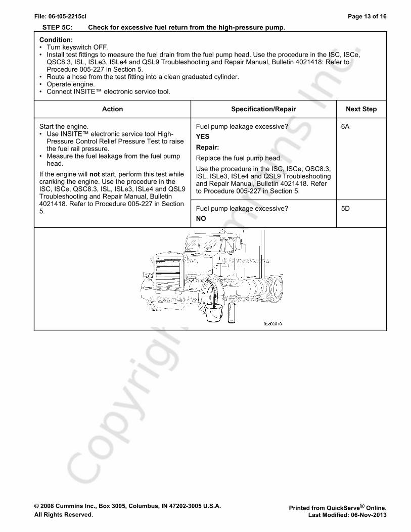
STEP 5C: Check for excessive fuel return from the high-pressure pump.
Condition:• Turn keyswitch OFF.• Install test fittings to measure the fuel drain from the fuel pump head. Use the procedure in the ISC, ISCe,
QSC8.3, ISL, ISLe3, ISLe4 and QSL9 Troubleshooting and Repair Manual, Bulletin 4021418: Refer toProcedure 005-227 in Section 5.
• Route a hose from the test fitting into a clean graduated cylinder.• Operate engine.• Connect INSITE™ electronic service tool.
Action Specification/Repair Next Step
Start the engine.• Use INSITE™ electronic service tool High-
Pressure Control Relief Pressure Test to raisethe fuel rail pressure.
• Measure the fuel leakage from the fuel pumphead.
If the engine will not start, perform this test whilecranking the engine. Use the procedure in theISC, ISCe, QSC8.3, ISL, ISLe3, ISLe4 and QSL9Troubleshooting and Repair Manual, Bulletin4021418. Refer to Procedure 005-227 in Section5.
Fuel pump leakage excessive?YESRepair:Replace the fuel pump head.Use the procedure in the ISC, ISCe, QSC8.3,ISL, ISLe3, ISLe4 and QSL9 Troubleshootingand Repair Manual, Bulletin 4021418. Referto Procedure 005-227 in Section 5.
6A
Fuel pump leakage excessive?NO
5D

© 2008 Cummins Inc., Box 3005, Columbus, IN 47202-3005 U.S.A. Printed from QuickServe® Online.All Rights Reserved. Last Modified: 06-Nov-2013
File: 06-t05-2215cl Page 14 of 16
STEP 5D: Check for excessive fuel return from the rail fuel pressure relief valve.
Condition:• Turn keyswitch OFF.• Install test fittings to measure the fuel drain from the rail fuel pressure relief valve. Use the procedure in the ISC,
ISCe, QSC8.3, ISL, ISLe3, ISLe4 and QSL9 Troubleshooting and Repair Manual, Bulletin 4021418: Refer toProcedure 006-061 in Section 6.
Action Specification/Repair Next Step
Start the engine.• Use INSITE™ electronic service tool High-
Pressure Control Relief Pressure Test to raisethe fuel rail pressure.
• Measure the fuel leakage from the fuel railpressure relief valve.
If the engine will not start, perform this test whilecranking the engine. Use the procedure in theISC, ISCe, QSC8.3, ISL, ISLe3, ISLe4 and QSL9Troubleshooting and Repair Manual, Bulletin4021418. Refer to Procedure 006-061 in Section6.
Fail fuel pressure relief valve leaking morethan 30 drops per minute?YESRepair:Replace the rail fuel pressure relief valve.Use the procedure in the ISC, ISCe, QSC8.3,ISL, ISLe3, ISLe4 and QSL9 Troubleshootingand Repair Manual, Bulletin 4021418. Referto Procedure 006-061 in Section 6.
6A
Fail fuel pressure relief valve leaking morethan 30 drops per minute?NO
6A

© 2008 Cummins Inc., Box 3005, Columbus, IN 47202-3005 U.S.A. Printed from QuickServe® Online.All Rights Reserved. Last Modified: 06-Nov-2013
File: 06-t05-2215cl Page 15 of 16
STEP 6: Verify the repair is complete.STEP 6A: Disable the fault code.
Condition:• Operate engine.• Connect INSITE™ electronic service tool.
Action Specification/Repair Next Step
Use INSITE™ electronic service tool to clear thefault code.• Road test the engine.• Use INSITE™ electronic service tool to read
the fault codes.
Fault Code 2215 become active duringloaded engine operation?YESRepair:Return to the troubleshooting steps orcontact a Cummins® Authorized RepairLocation if all steps have been completedand checked again.
1A
Fault Code 2215 become active duringloaded engine operation?NO
6B
STEP 6B: Clear the inactive fault codes.
Condition:• Connect all components.• Turn keyswitch ON.• Connect INSITE™ electronic service tool.
Action Specification/Repair Next Step
Clear the inactive fault codes.• Use INSITE™ electronic service tool to clear
the inactive fault codes.
All fault codes cleared?YES
Repaircomplete
All fault codes cleared?NORepair:Troubleshoot any remaining fault codes.
Appropriatetroubleshooting trees

© 2008 Cummins Inc., Box 3005, Columbus, IN 47202-3005 U.S.A. Printed from QuickServe® Online.All Rights Reserved. Last Modified: 06-Nov-2013
File: 06-t05-2215cl Page 16 of 16


![BDDrFVIII (Moroctocog alfa [AF-CC]) for surgical ...either BI or CI for the management of surgical haemostasis in patients with severe and moderately severe haemophilia A undergoing](https://img.pdfslide.net/doc/110x75/5ec669a2334553147508b329/bddrfviii-moroctocog-alfa-af-cc-for-surgical-either-bi-or-ci-for-the-management.jpg)