Embed Size (px)
Citation preview
Operation and Applications of Differential Flow Modulation
FID
Column 1
Column 2
Collection channel
H2
H2
GCxGC eseminar Oct. 2010
Page 1
Roger L Firor, Ph.D.Agilent TechnologiesChemical Analysis GroupWilmington, DE USA
Flow Modulator
Outline
• GC X GC Basics
• Flow modulation using CFT (Capillary Flow Technology)
• Performance and operating characteristics: GC and MSD
• Configurations and applications for heavy hydrocarbons
GCxGC eseminar Oct. 2010
Page 2
• Configurations and applications for light hydrocarbons
• Summary
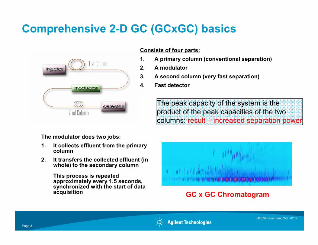
Comprehensive 2-D GC (GCxGC) basics
Consists of four parts:
1. A primary column (conventional separation)
2. A modulator
3. A second column (very fast separation)
4. Fast detector
The peak capacity of the system is the product of the peak capacities of the twocolumns: result – increased separation power
GCxGC eseminar Oct. 2010
Page 3
The modulator does two jobs:
1. It collects effluent from the primary column
2. It transfers the collected effluent (in whole) to the secondary column
This process is repeated approximately every 1.5 seconds, synchronized with the start of data acquisition GC x GC Chromatogram
columns: result – increased separation power
OverviewPulsed flow modulation (PFM) is an option for implementation of comprehensive GCxGC
Strengths:
• Does not require cryogen• Simple to construct (connection fittings, three-way gas switching valve, a timing device)• Ideal for fast moving molecules• Low cost of ownership
Limitations:
4
Limitations:
• Unlike thermal modulation where modulation period can be readily change, parameter optimization can be more intensive
Objectives:
• Demonstrate the reliability, flexibility, and ease of use of Agilent capillary flow modulator in PFM-GCxGC
• Articulate utility of said device with practical industrial applications– Compatibility with both partition (WCOT) and adsorption (PLOT) chromatography
GCxGC eseminar Oct. 2010
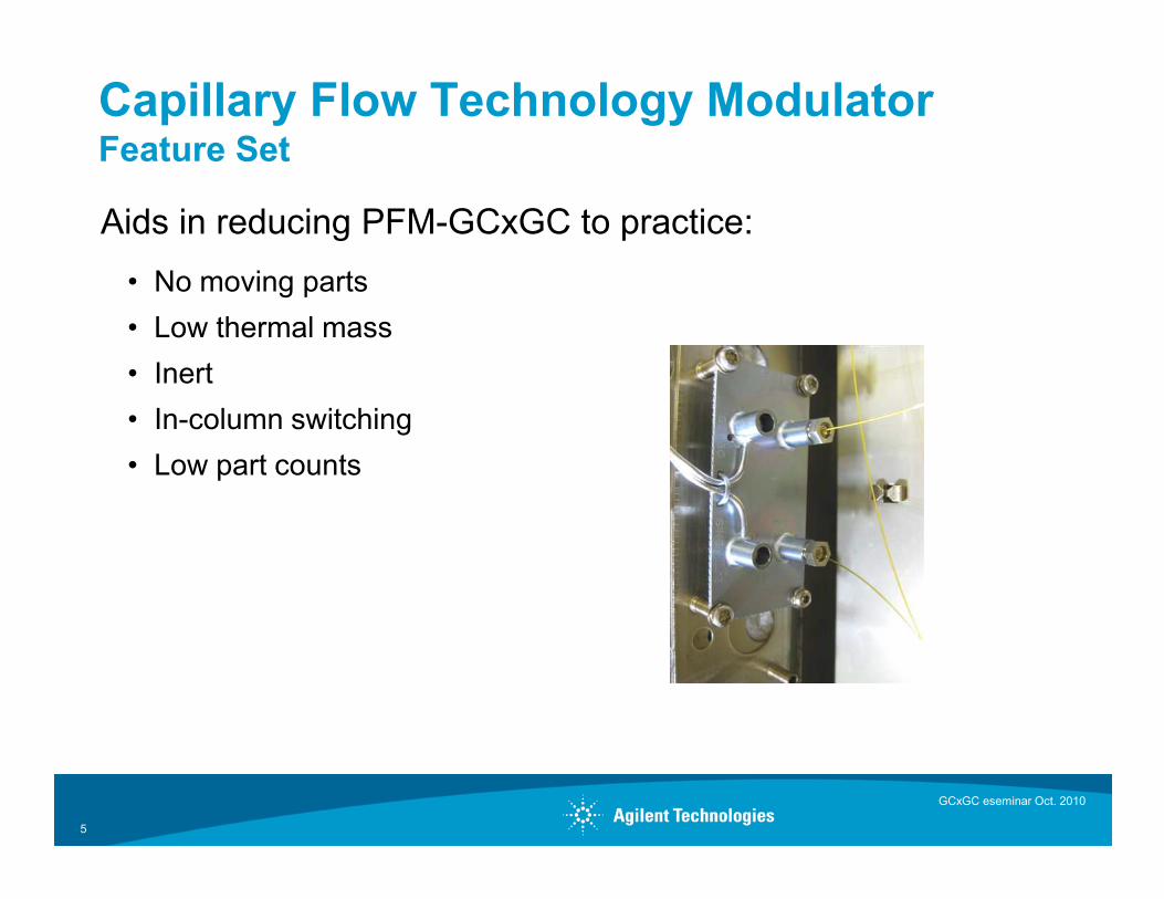
Capillary Flow Technology ModulatorFeature Set
Aids in reducing PFM-GCxGC to practice:
• No moving parts
• Low thermal mass
• Inert
• In-column switching
• Low part counts
5
• Low part counts
GCxGC eseminar Oct. 2010
Basic Configuration
Hardware
7890A GC
Split/splitless inlet, hydrogen carrier gas
PCM module
Valve driver and timing board (7890A)
Three way modulation valve
Capillary Flow Technology modulator device
GCxGC eseminar Oct. 2010
Page 6
Capillary Flow Technology modulator device
Two columns: 30m x 0.25mm non-polar, 5m x 0.25mm polar (typical)
FID at 200 Hz
7683 Auto Injector
Data processing softwareCG Image, LLC, Lincoln NE 68505
Zoex Corporation, Pasadena, TX 77505
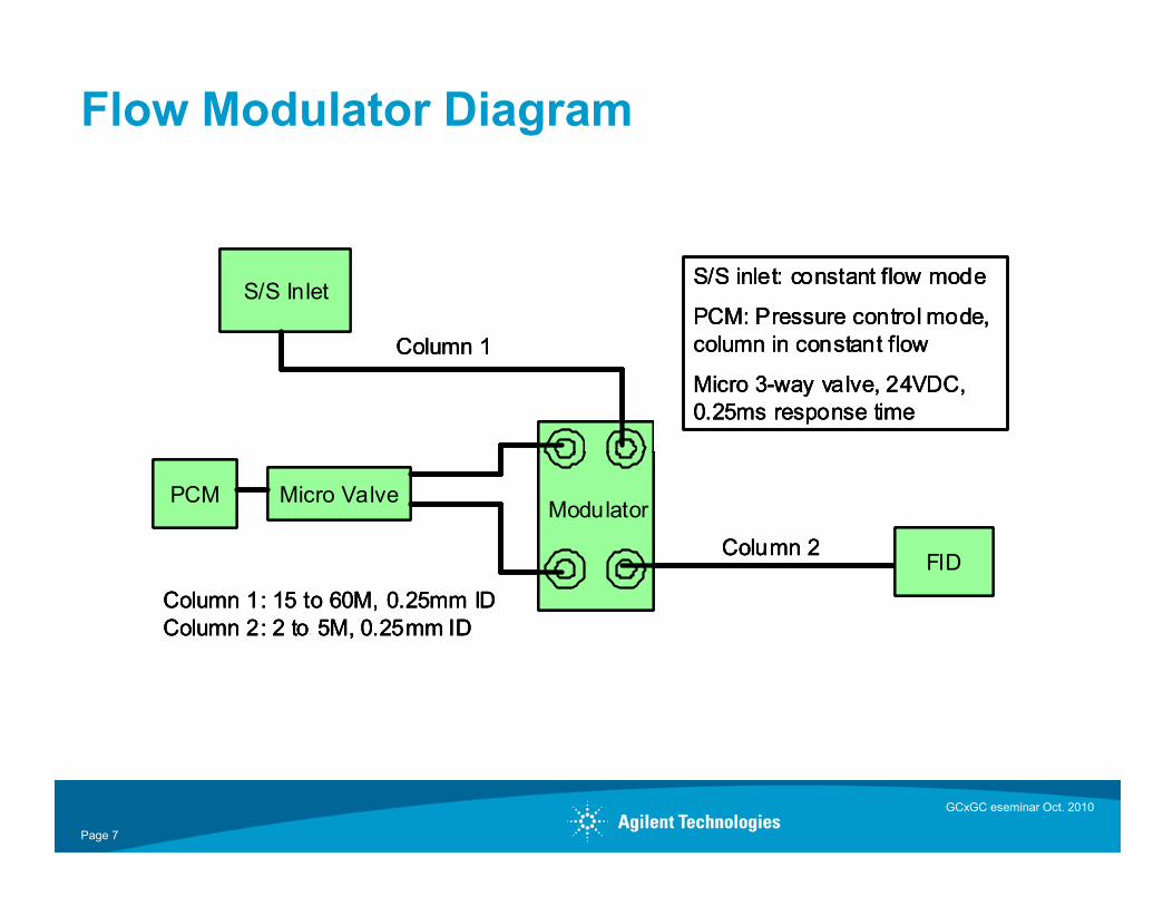
Flow Modulator Diagram
S/S Inlet
Column 1
S/S inlet: constant flow mode
PCM: Pressure control mode, column in constant flow
Micro 3-way valve, 24VDC, 0.25ms response time
S/S Inlet
Column 1
S/S inlet: constant flow mode
PCM: Pressure control mode, column in constant flow
Micro 3-way valve, 24VDC, 0.25ms response time
S/S Inlet
Column 1
S/S inlet: constant flow mode
PCM: Pressure control mode, column in constant flow
Micro 3-way valve, 24VDC, 0.25ms response time
GCxGC eseminar Oct. 2010
Page 7
FIDColumn 2
PCM Micro ValveModulator
Column 1: 15 to 60M, 0.25mm IDColumn 2: 2 to 5M, 0.25mm ID
FIDColumn 2
PCM Micro ValveModulator
Column 1: 15 to 60M, 0.25mm IDColumn 2: 2 to 5M, 0.25mm ID
FIDColumn 2
PCM Micro ValveModulator
Column 1: 15 to 60M, 0.25mm IDColumn 2: 2 to 5M, 0.25mm ID
Constraints
Since the collection channel is fixed …
Flow rates cannot be varied by large amounts
Modulation timing depends on first column flow rate
Second column flow is always high, typically 21 ml/min
Hydrogen carrier should be used although Helium is possible
GCxGC eseminar Oct. 2010
Page 8
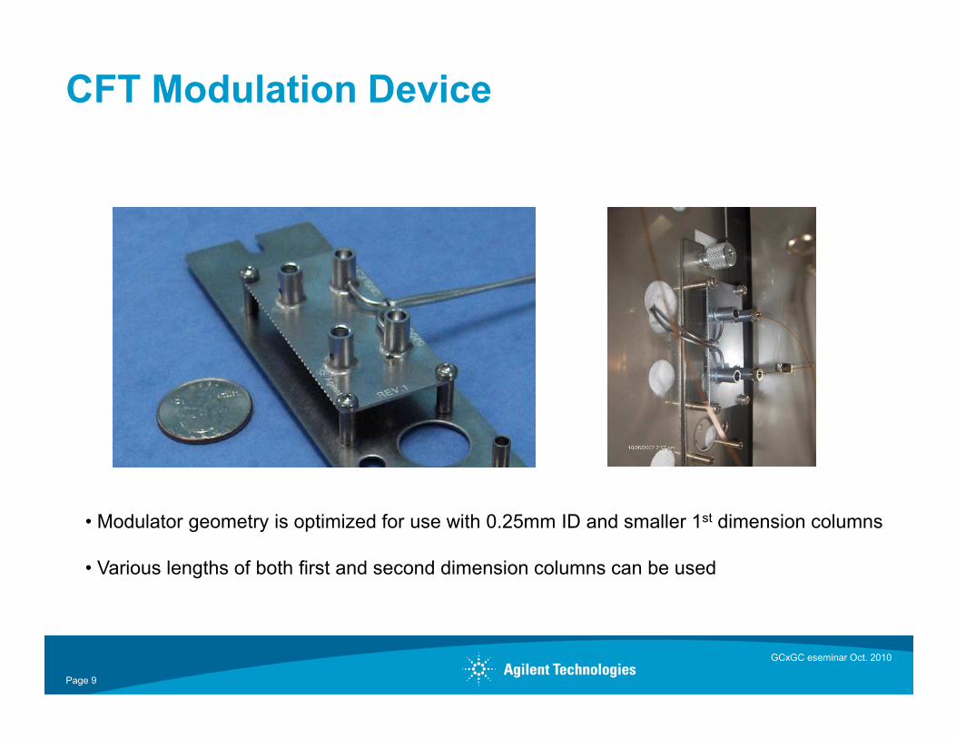
CFT Modulation Device
GCxGC eseminar Oct. 2010
Page 9
• Modulator geometry is optimized for use with 0.25mm ID and smaller 1st dimension columns
• Various lengths of both first and second dimension columns can be used
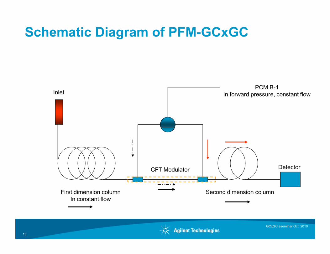
Schematic Diagram of PFM-GCxGC
InletPCM B-1
In forward pressure, constant flow
10
First dimension columnIn constant flow
Second dimension column
DetectorCFT Modulator
GCxGC eseminar Oct. 2010
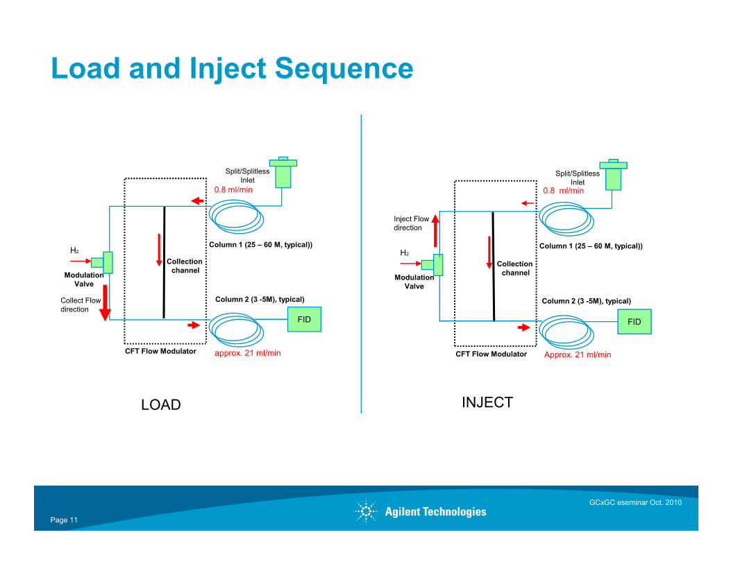
Load and Inject Sequence
ModulationValve
Split/SplitlessInlet
Column 1 (25 – 60 M, typical))
Collection channel
H2
0.8 ml/min
ModulationValve
Split/SplitlessInlet
Collection channel
H2
Inject Flow direction
0.8 ml/min
Column 1 (25 – 60 M, typical))
GCxGC eseminar Oct. 2010
Page 11
Valve
FID
Column 2 (3 -5M), typical)
CFT Flow Modulator
Collect Flow direction
approx. 21 ml/min
Valve
FID
CFT Flow Modulator Approx. 21 ml/min
Column 2 (3 -5M), typical)
LOAD INJECT
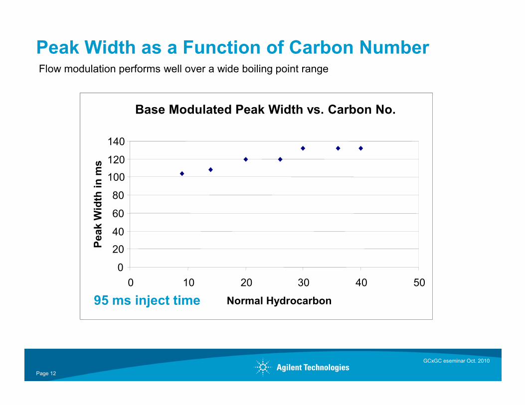
Peak Width as a Function of Carbon NumberFlow modulation performs well over a wide boiling point range
Base Modulated Peak Width vs. Carbon No.
80
100
120
140
Pea
l Wid
th in
ms
Base Modulated Peak Width vs. Carbon No.
80
100
120
140
Pea
k W
idth
in m
s
GCxGC eseminar Oct. 2010
Page 12
0
20
40
60
0 10 20 30 40 50
Normal Hydrocarbon
Pea
l Wid
th in
ms
95 ms inject time
0
20
40
60
0 10 20 30 40 50
Normal Hydrocarbon
Pea
k W
idth
in m
s
95 ms inject time
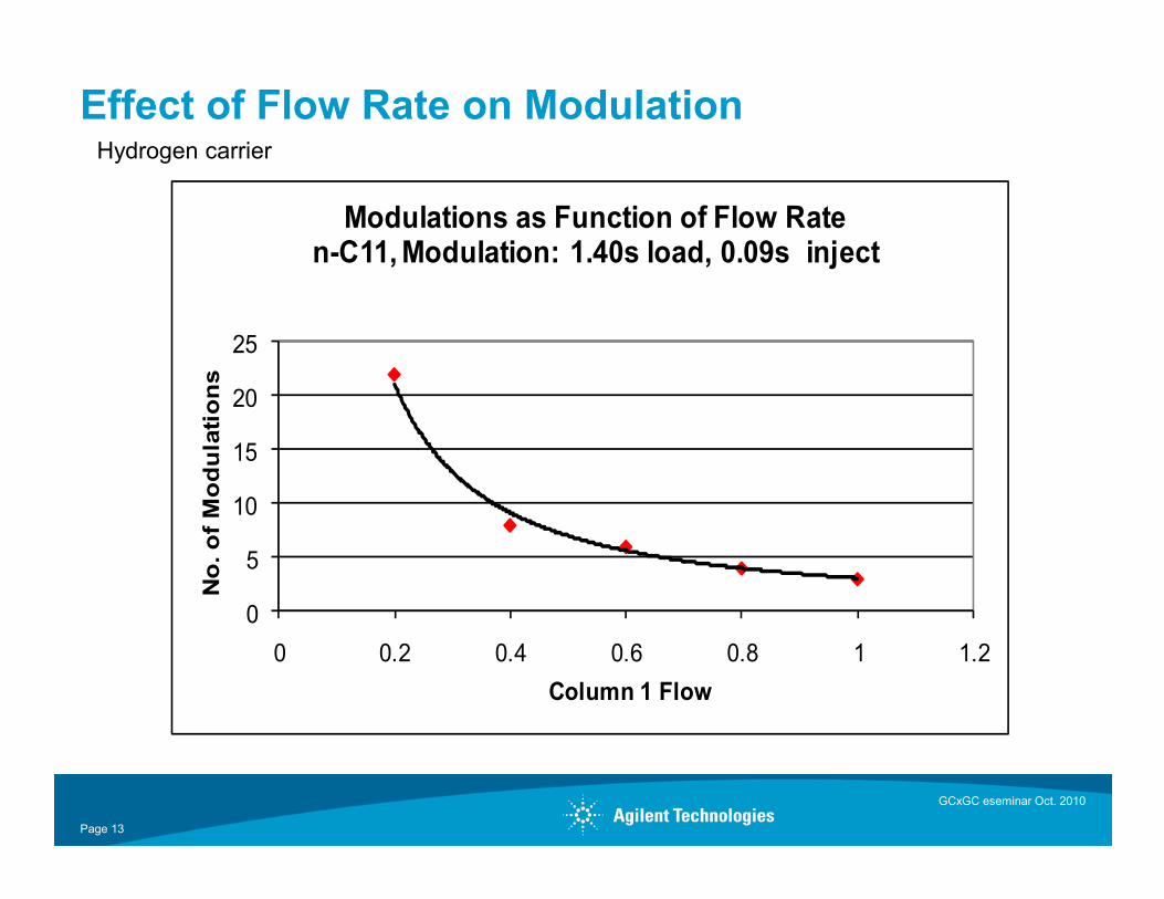
Effect of Flow Rate on Modulation
15
20
25
No. o
f M
odula
tions
Modulations as Function of Flow Raten-C11, Modulation: 1.40s load, 0.09s inject
Hydrogen carrier
GCxGC eseminar Oct. 2010
Page 13
0
5
10
15
0 0.2 0.4 0.6 0.8 1 1.2
No. o
f M
odula
tions
Column 1 Flow
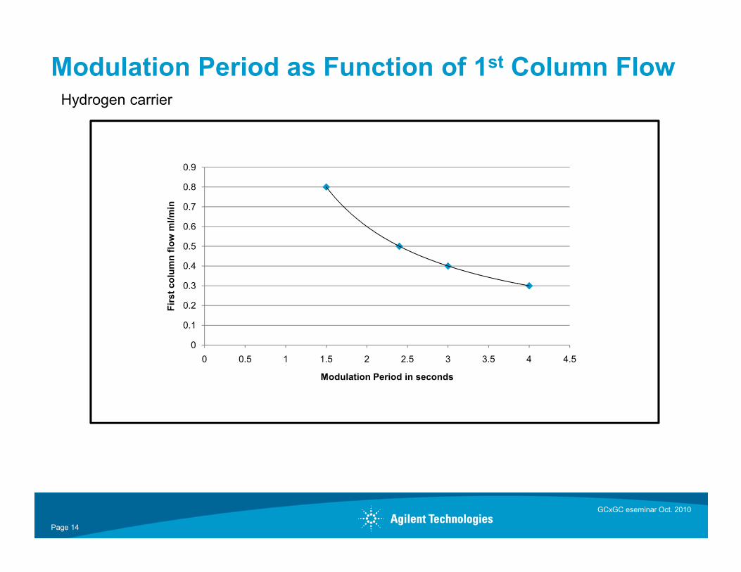
Modulation Period as Function of 1st Column Flow
0.3
0.4
0.5
0.6
0.7
0.8
0.9First
colu
mn flo
w m
l/min
Hydrogen carrier
GCxGC eseminar Oct. 2010
Page 14
0
0.1
0.2
0.3
0 0.5 1 1.5 2 2.5 3 3.5 4 4.5
First
colu
mn flo
w m
l/min
Modulation Period in seconds
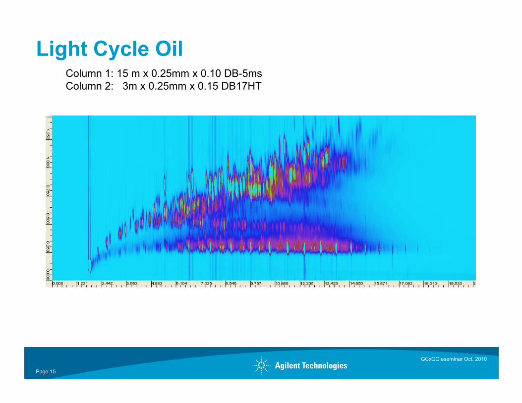
Light Cycle OilColumn 1: 15 m x 0.25mm x 0.10 DB-5msColumn 2: 3m x 0.25mm x 0.15 DB17HT
GCxGC eseminar Oct. 2010
Page 15
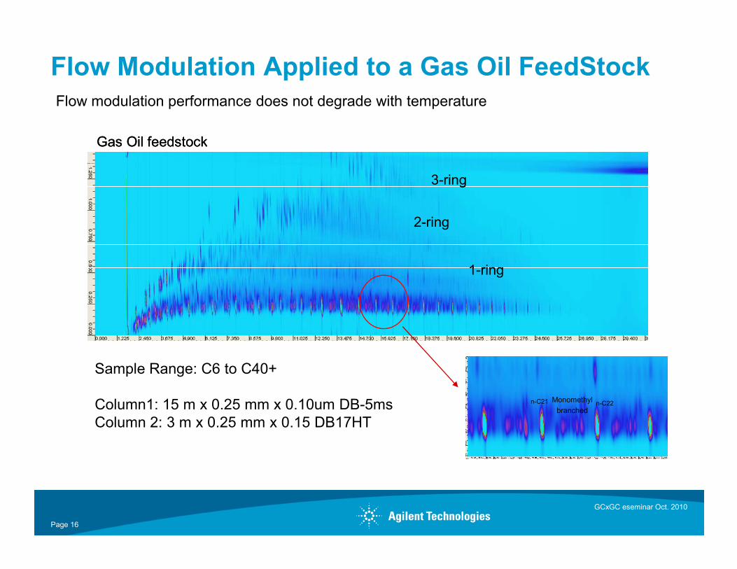
Flow Modulation Applied to a Gas Oil FeedStock
Gas Oil feedstock
3-ring
2-ring
1-ring
Gas Oil feedstock
3-ring
2-ring
3-ring
2-ring
1-ring
Flow modulation performance does not degrade with temperature
GCxGC eseminar Oct. 2010
Page 16
Sample Range: C6 to C40+
Column1: 15 m x 0.25 mm x 0.10um DB-5msColumn 2: 3 m x 0.25 mm x 0.15 DB17HT
n-C22Monomethylbranched
n-C21 n-C22Monomethylbranched
n-C21
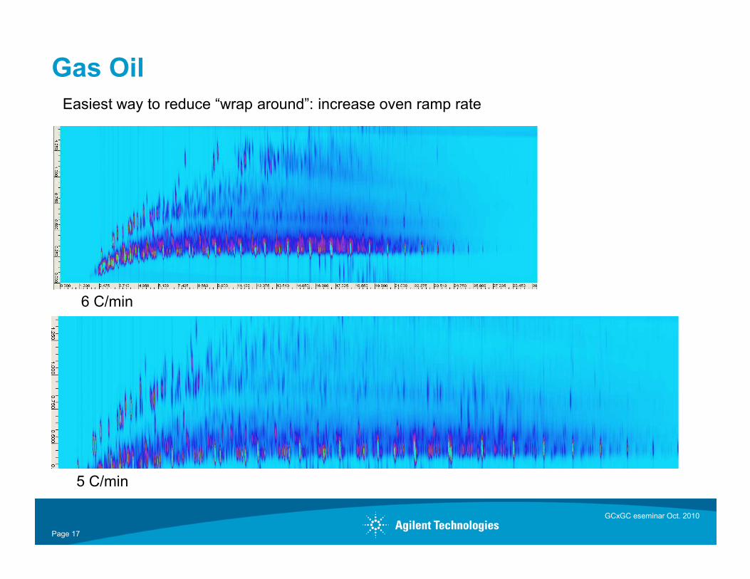
Gas OilEasiest way to reduce “wrap around”: increase oven ramp rate
GCxGC eseminar Oct. 2010
Page 17
5 C/min
6 C/min
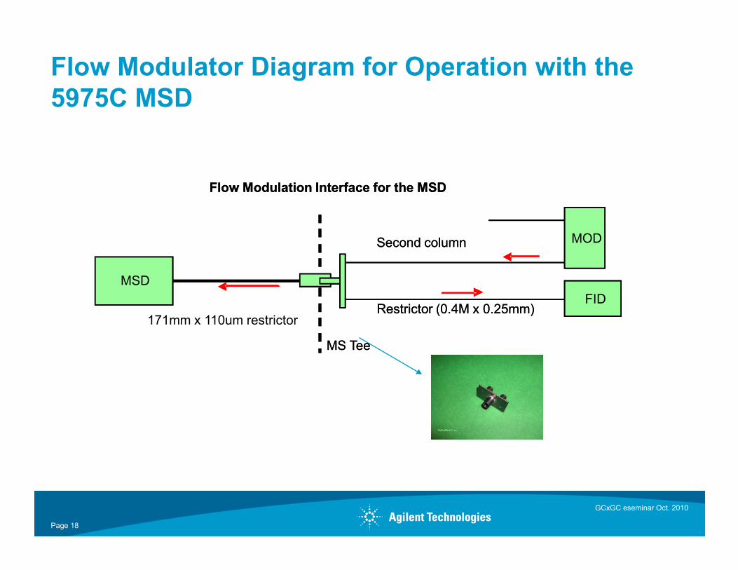
Flow Modulator Diagram for Operation with the5975C MSD
Flow Modulation Interface for the MSDFlow Modulation Interface for the MSD
Second column MOD
MSD
Second column MOD
MSD
GCxGC eseminar Oct. 2010
Page 18
MS TeeMS Tee
171mm x 110um restrictorRestrictor (0.4M x 0.25mm)
FIDMSD
Restrictor (0.4M x 0.25mm)FID
MSD
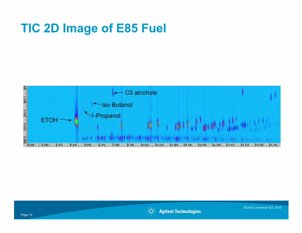
TIC 2D Image of E85 Fuel
C5 alcohols
Iso Butanol
1-Propanol
Page 19
ETOH1-Propanol
GCxGC eseminar Oct. 2010
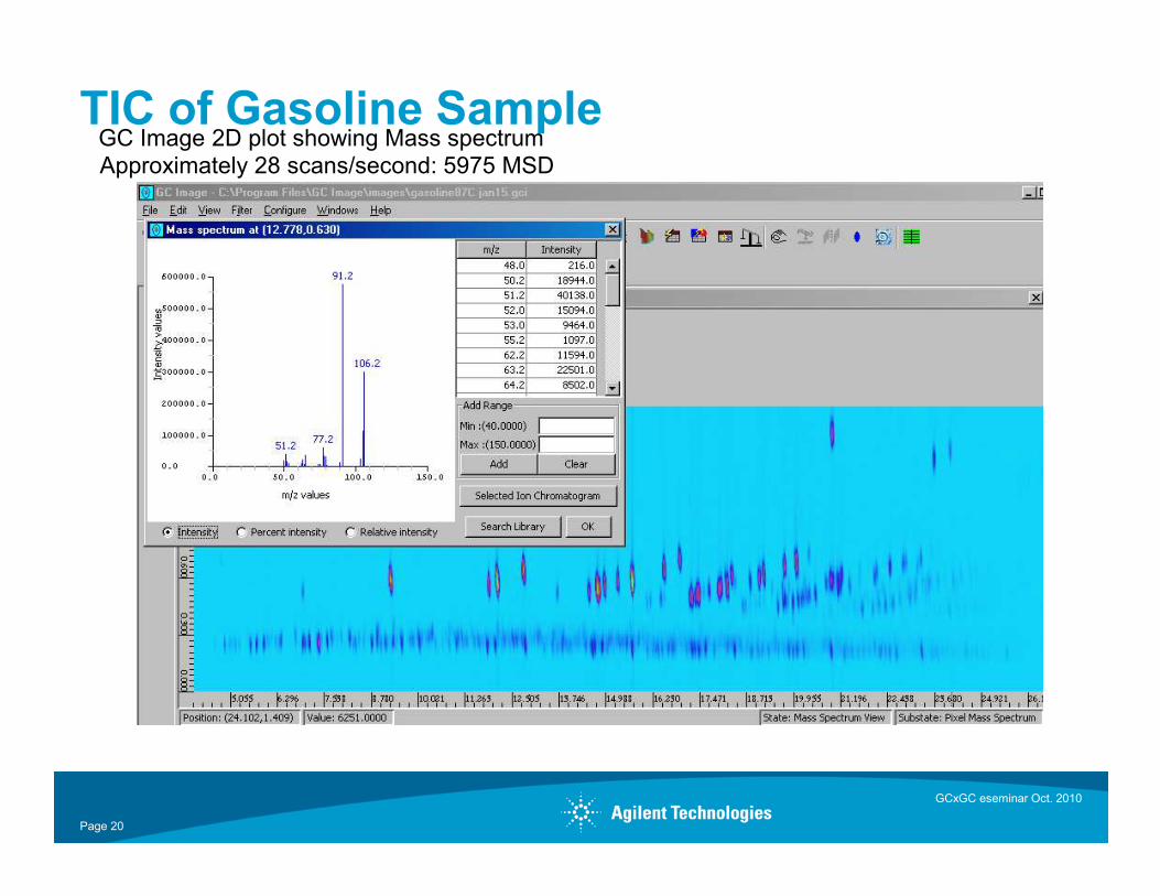
TIC of Gasoline SampleGC Image 2D plot showing Mass spectrum Approximately 28 scans/second: 5975 MSD
Page 20
GCxGC eseminar Oct. 2010
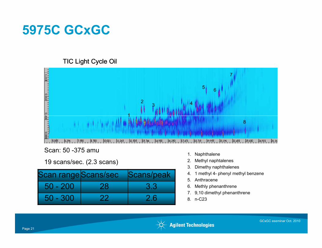
5975C GCxGC
TIC Light Cycle Oil
1
23 4
5 6
7
8
TIC Light Cycle Oil
1
23 4
5 6
7
8
GCxGC eseminar Oct. 2010
Page 21
88
1. Naphthalene2. Methyl naphtalenes3. Dimethy naphthalenes4. 1 methyl 4- phenyl methyl benzene5. Anthracene6. Methly phenanthrene7. 9,10 dimethyl phenanthrene8. n-C23
Scan: 50 -375 amu
19 scans/sec. (2.3 scans)
Scan rangeScans/sec Scans/peak50 - 200 28 3.350 - 300 22 2.6
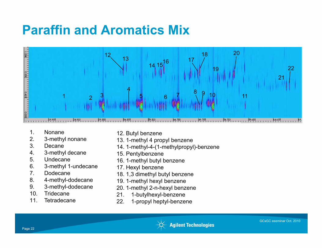
Paraffin and Aromatics Mix
1 2 34
5 6 7 8 9 10 11
1213
14 1516 17
18
19
20
21
22
GCxGC eseminar Oct. 2010
Page 22
1. Nonane2. 3-methyl nonane3. Decane4. 3-methyl decane5. Undecane6. 3-methyl 1-undecane7. Dodecane8. 4-methyl-dodecane9. 3-methyl-dodecane10. Tridecane11. Tetradecane
12. Butyl benzene13. 1-methyl 4 propyl benzene14. 1-methyl-4-(1-methylpropyl)-benzene15. Pentylbenzene16. 1-methyl butyl benzene17. Hexyl benzene18. 1,3 dimethyl butyl benzene19. 1-methyl hexyl benzene20. 1-methyl 2-n-hexyl benzene21. 1-butylhexyl-benzene22. 1-propyl heptyl-benzene
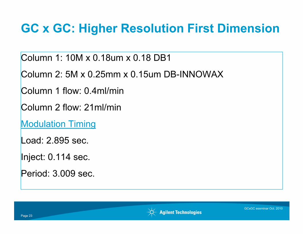
GC x GC: Higher Resolution First Dimension
Column 1: 10M x 0.18um x 0.18 DB1
Column 2: 5M x 0.25mm x 0.15um DB-INNOWAX
Column 1 flow: 0.4ml/min
Column 2 flow: 21ml/min
Modulation Timing
Load: 2.895 sec.
Inject: 0.114 sec.
Period: 3.009 sec.
Page 23
GCxGC eseminar Oct. 2010
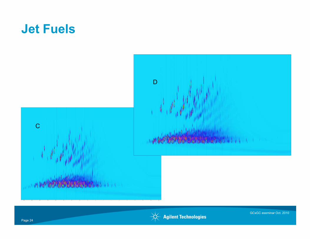
Jet Fuels
D
Page 24
GCxGC eseminar Oct. 2010
C
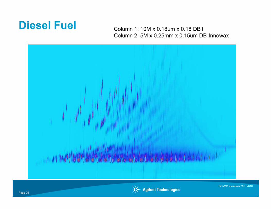
Diesel Fuel Column 1: 10M x 0.18um x 0.18 DB1Column 2: 5M x 0.25mm x 0.15um DB-Innowax
Page 25
GCxGC eseminar Oct. 2010
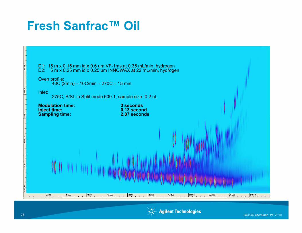
Fresh Sanfrac™ Oil
D1: 15 m x 0.15 mm id x 0.6 um VF-1ms at 0.35 mL/min, hydrogenD2: 5 m x 0.25 mm id x 0.25 um INNOWAX at 22 mL/min, hydrogen
Oven profile:40C (2min) – 10C/min – 270C – 15 min
Inlet:275C, S/SL in Split mode 600:1, sample size: 0.2 uL
Modulation time: 3 secondsInject time: 0.13 secondSampling time: 2.87 seconds
GCxGC eseminar Oct. 201026
Sampling time: 2.87 seconds
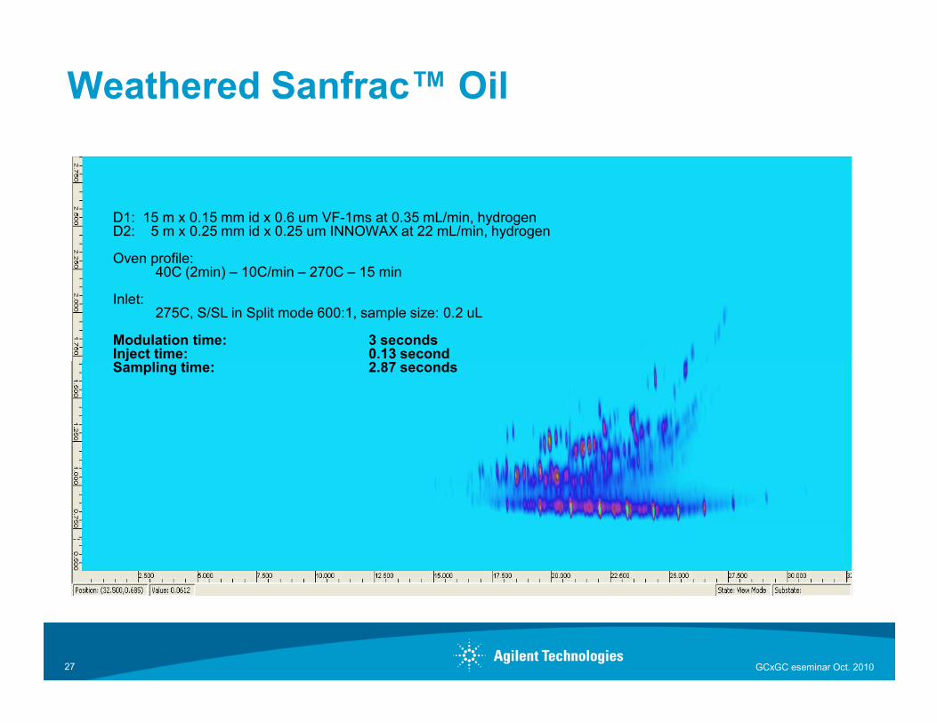
Weathered Sanfrac™ Oil
D1: 15 m x 0.15 mm id x 0.6 um VF-1ms at 0.35 mL/min, hydrogenD2: 5 m x 0.25 mm id x 0.25 um INNOWAX at 22 mL/min, hydrogen
Oven profile:40C (2min) – 10C/min – 270C – 15 min
Inlet:275C, S/SL in Split mode 600:1, sample size: 0.2 uL
Modulation time: 3 secondsInject time: 0.13 secondSampling time: 2.87 seconds
GCxGC eseminar Oct. 201027
Sampling time: 2.87 seconds
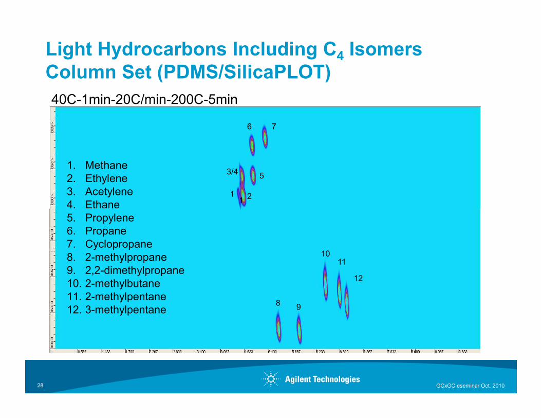
Light Hydrocarbons Including C4 IsomersColumn Set (PDMS/SilicaPLOT)40C-1min-20C/min-200C-5min
1. Methane2. Ethylene3. Acetylene4. Ethane
11 2
3/4
6
5
7
GCxGC eseminar Oct. 201028
4. Ethane5. Propylene6. Propane7. Cyclopropane8. 2-methylpropane9. 2,2-dimethylpropane10. 2-methylbutane11. 2-methylpentane12. 3-methylpentane
8 9
1011
12
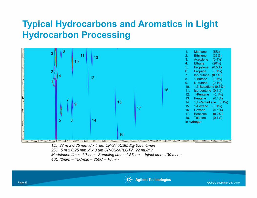
1. Methane (5%)2. Ethylene (35%)3. Acetylene (0.4%)4. Ethane (20%)5. Propylene (0.5%)6. Propane (0.1%)7. Iso-butane (0.1%)8. 1-Butene (0.1%)9. N-butane (0.1%)10. 1,3-Butadiene (0.5%)11. Iso-pentane (0.1%)12. 1-Pentene (0.1%)13. Pentane (0.1%)
18
1
3
24
6
7
10
11
12
13
Typical Hydrocarbons and Aromatics in Light Hydrocarbon Processing
GCxGC eseminar Oct. 2010
1D: 27 m x 0.25 mm id x 1 um CP-Sil 5CBMS@ 0.8 mL/min2D: 5 m x 0.25 mm id x 3 um CP-SilicaPLOT@ 22 mL/minModulation time: 1.7 sec Sampling time: 1.57sec Inject time: 130 msec40C (2min) – 15C/min – 250C – 10 min
13. Pentane (0.1%)14. 1,4-Pentadiene (0.1%)15. 1-Hexene (0.1%)16. Hexane (0.1%)17. Benzene (0.2%)18. Toluene (0.1%)In hydrogen
17
15
14
16
5 8
79
Page 29
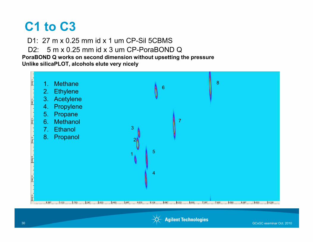
C1 to C3D1: 27 m x 0.25 mm id x 1 um CP-Sil 5CBMSD2: 5 m x 0.25 mm id x 3 um CP-PoraBOND Q
PoraBOND Q works on second dimension without upsetting the pressure Unlike silicaPLOT, alcohols elute very nicely
1. Methane2. Ethylene3. Acetylene4. Propylene5. Propane6. Methanol 7
68
GCxGC eseminar Oct. 201030
6. Methanol7. Ethanol8. Propanol
1
2
5
4
7
3
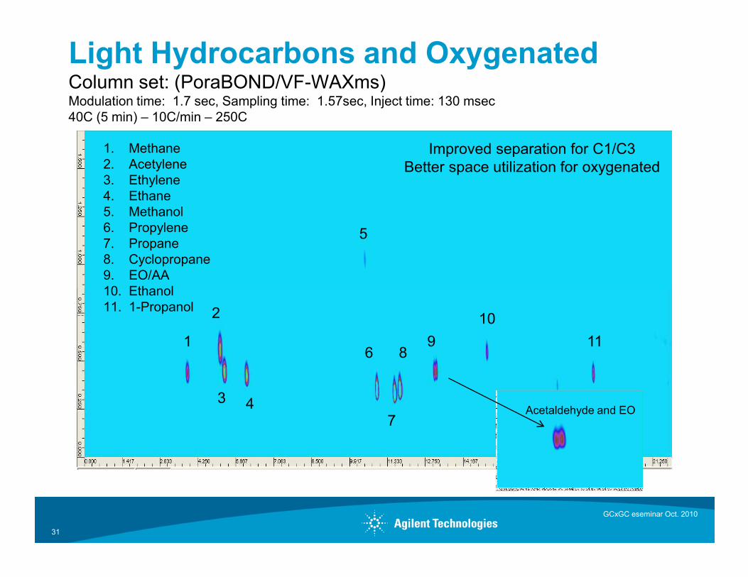
Light Hydrocarbons and OxygenatedColumn set: (PoraBOND/VF-WAXms)Modulation time: 1.7 sec, Sampling time: 1.57sec, Inject time: 130 msec40C (5 min) – 10C/min – 250C
5
1. Methane2. Acetylene3. Ethylene4. Ethane5. Methanol6. Propylene7. Propane8. Cyclopropane9. EO/AA10. Ethanol
Improved separation for C1/C3Better space utilization for oxygenated
31
1
2
43
6 89
7
10
11
10. Ethanol11. 1-Propanol
GCxGC eseminar Oct. 2010
Acetaldehyde and EO
Combining Pre-column Backflush with GCxGC
• Investigate possibility of analyzing heavy crudes with comprehensive gas chromatography
• Apply chemometrics to identify source or contamination
• Process 50 Hz raw data files
• Analyze four different crudes
• Column set
• First Dimension: 30 m x 0.25 mm x 0.10 um DB-5HT
• Second Dimension : 5 m x 0.25 mm x 0.15 um DB-17HT
GCxGC eseminar Oct. 2010
Page 32
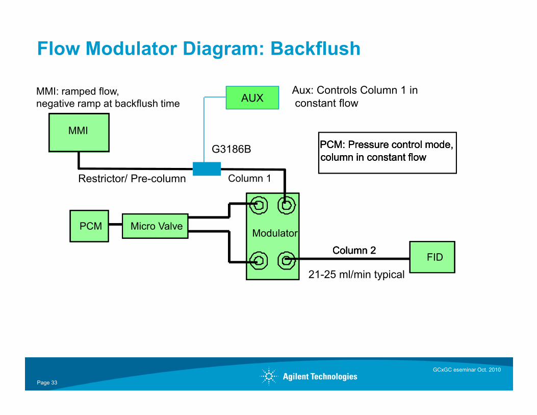
Flow Modulator Diagram: Backflush
MMI: ramped flow, negative ramp at backflush time
PCM: Pressure control mode, column in constant flowPCM: Pressure control mode, column in constant flow
MMI
Column 1
PCM: Pressure control mode, column in constant flow
AUX
Restrictor/ Pre-column
G3186B
Aux: Controls Column 1 inconstant flow
GCxGC eseminar Oct. 2010
Page 33
FIDColumn 2
PCM Micro ValveModulator
FIDColumn 2
PCM Micro ValveModulator
FIDColumn 2
PCM Micro ValveModulator
21-25 ml/min typical
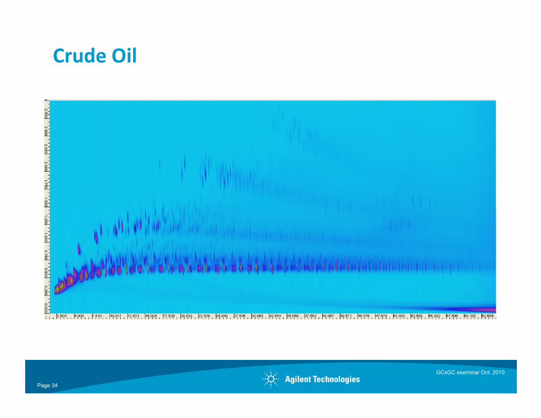
Crude Oil
Page 34
GCxGC eseminar Oct. 2010
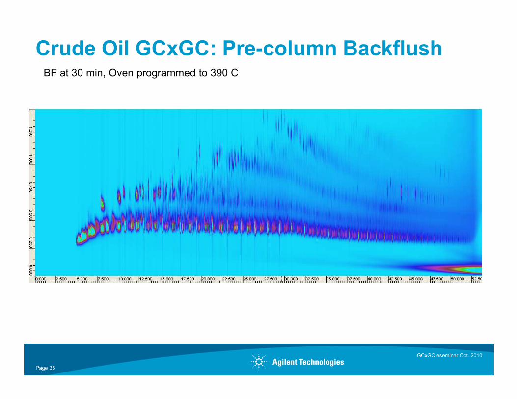
Crude Oil GCxGC: Pre-column BackflushBF at 30 min, Oven programmed to 390 C
GCxGC eseminar Oct. 2010
Page 35
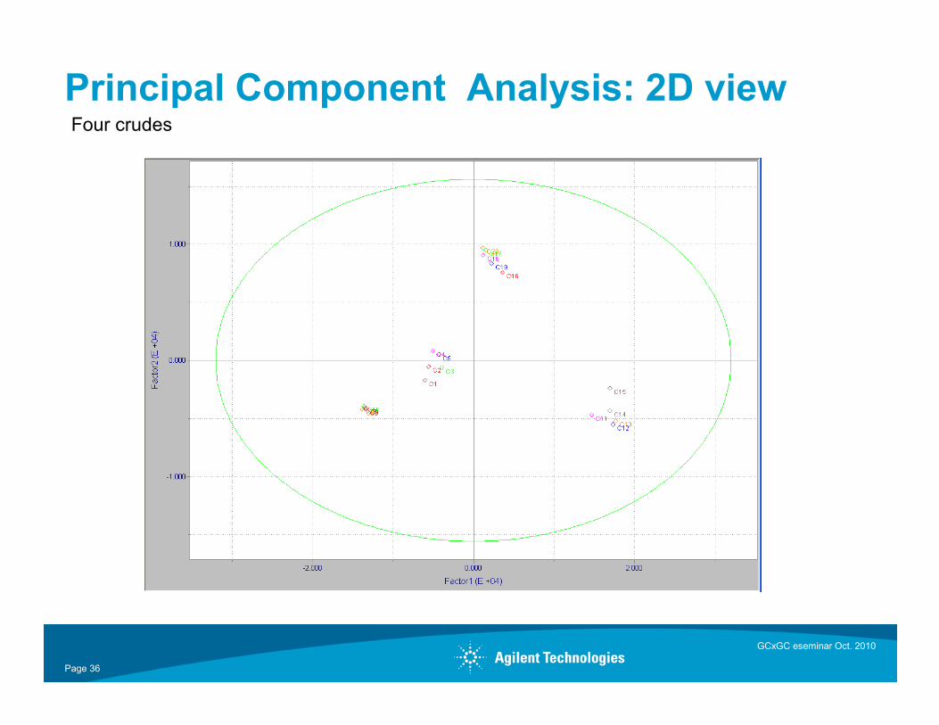
Principal Component Analysis: 2D viewFour crudes
GCxGC eseminar Oct. 2010
Page 36
Key Observations
ØHigher separation power achieved by using narrow borecolumns in first dimension
ØSamples at the extreme ends of the boiling point range can beseparated
ØVarious combinations of WCOT/PLOT can be configured toaddress a variety of light hydrocarbon separations as analternative of traditional valved systems.
GCxGC eseminar Oct. 2010
Page 37
alternative of traditional valved systems.
ØPoraBOND or SilicaPLOT columns can be used for either thefirst or second dimension column .
ØDue the high second dimension column flow, care must betaken to avoid backpressure that would upset operation ofpulsed flow modulation.
Summary
PFM-GCxGC is particularly useful for:• Fast moving molecules, light hydrocarbons, light chlorinated hydrocarbons, and oxygenated compounds
• Well suited for heavy hydrocarbon, can operate over 400C • Complimentary technique for GC/MS for characterization of fuel and lubricants
Ø Capillary flow technology modulator can be implemented in production
38
Ø Capillary flow technology modulator can be implemented in production laboratories
Ø Compatibility with adsorption chromatography as illustrated with Silica and DVB based columns
Ø Hardware available as G3440A Opt #887 and G3487A (“kit”) on the 7890A
GCxGC eseminar Oct. 2010