Embed Size (px)
Citation preview
Complete with intelliCode Remote ContRol and SeRieS ii eleCtRoniCS
table of ContentS
Warranty Information . . . . . . . . . . . . . . . . . . . 2
Safety Information . . . . . . . . . . . . . . . . . . . . . 3
Safety Features . . . . . . . . . . . . . . . . . . . . . . . . . 3
Important Installation Instructions . . . . . . . 3
Pre-Installation Checklist . . . . . . . . . . . . . . 4-6
Adjustments . . . . . . . . . . . . . . . . . . . . . . . . . . 7-8
Programming the Remote Control . . . . 8-9
Installing Lightbulb and Lens . . . . . . . . . . . . 9
Scheduled Maintenance . . . . . . . . . . . . . . . 10
Troubleshooting Guide . . . . . . . . . . . . .10-11
Wiring Diagram . . . . . . . . . . . . . . . . . . . . . . . . 12
Parts Lists and Exploded Views . . . . . .12-13
Accessories . . . . . . . . . . . . . . . . . . . . . . . . . . . . 14
For up to 7’-6” tall Doors. (Extension Kit available for 8’ Doors)
Included Wall Control MUST be installed prior to Operation of this Garage Door Operator.
Safe-T-Beam® Safety Reverse System Must be Installed and the Force Controls MUST be Properly Set to close door.
This Equipment meets or exceeds all Federal, State and UL 325 Safety Requirements.
SAVE THIS M
ANUAL FOR
FUTURE REFERENCE
Having Difficulty? Need Help?Please call us: 1-800-35-GENIE (354-3643) www.geniecompany.com
Please have Model information ready when calling.
3624736189
®
AC POWERED SCREW DRIVE OPENERS
Operation and Maintenance Manual
2 For Help, call 1-800-35-GENIE or visit www.geniecompany.com
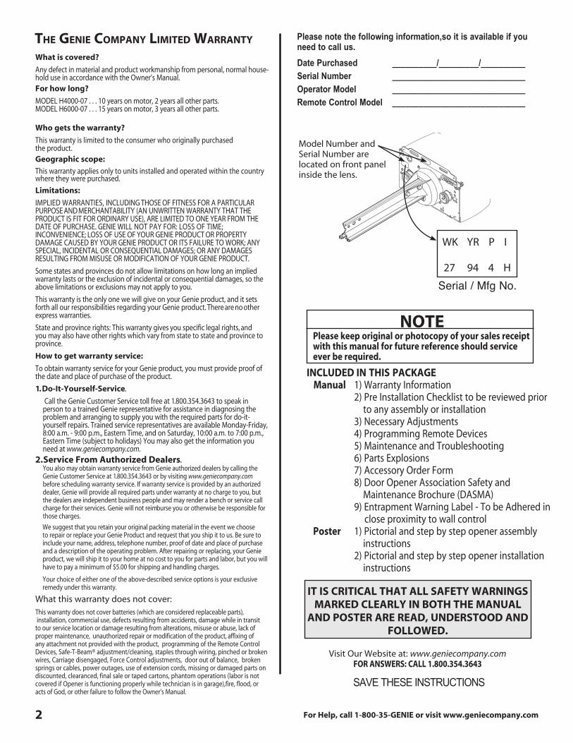
Model Number and Serial Number are located on front panel inside the lens .
IT IS CRITICAL THAT ALL SAFETY WARNINGS MARKED CLEARLY IN BOTH THE MANUAL
AND POSTER ARE READ, UNDERSTOOD AND FOLLOWED.
the Genie Company limited waRRanty
What is covered?
Any defect in material and product workmanship from personal, normal house-hold use in accordance with the Owner’s Manual .For how long?
MODEL H4000-07 . . . 10 years on motor, 2 years all other parts . MODEL H6000-07 . . . 15 years on motor, 3 years all other parts .
Who gets the warranty?
This warranty is limited to the consumer who originally purchased the product .Geographic scope:
This warranty applies only to units installed and operated within the country where they were purchased .
Limitations:
IMPLIED WARRANTIES, I N CLUDING THOSE OF FITNESS FOR A PAR TICULAR PURPOSE AND MERCHANT ABILITY (AN UNWRITTEN WARRANTY THAT THE PRODUCT IS FIT FOR ORDINARY USE), ARE LIMITED TO ONE YEAR FROM THE DATE OF PURCHASE . GENIE WILL NOT PAY FOR: LOSS OF TIME; INCONVENIENCE; LOSS OF USE OF YOUR GENIE PRODUCT OR PROPERTY DAMAGE CAUSED BY YOUR GENIE PRODUCT OR ITS FAILURE TO WORK; ANY SPECIAL, INCIDENTAL OR CONSEQUENTIAL DAMAGES; OR ANY DAMAGES RESULTING FROM MISUSE OR MODIFICATION OF YOUR GENIE PRODUCT .
Some states and provinces do not allow limitations on how long an implied warranty lasts or the exclusion of incidental or consequential damages, so the above limitations or exclusions may not apply to you .
This warranty is the only one we will give on your Genie product, and it sets forth all our responsibilities regarding your Genie product . There are no other express warranties .
State and province rights: This warranty gives you specific legal rights, and you may also have other rights which vary from state to state and province to province .
How to get warranty service:
To obtain warranty service for your Genie product, you must provide proof of the date and place of purchase of the product .
1. Do-It-Yourself-Service.
Call the Genie Customer Service toll free at 1 .800 .354 .3643 to speak in person to a trained Genie representative for assistance in diagnosing the problem and arranging to supply you with the required parts for do-it- yourself repairs . Trained service representatives are available Monday-Friday, 8:00 a .m . - 9:00 p .m ., Eastern Time, and on Saturday, 10:00 a .m . to 7:00 p .m ., Eastern Time (subject to holidays) You may also get the information you need at www.geniecompany.com .
2. Service From Authorized Dealers. You also may obtain warranty service from Genie authorized dealers by calling the Genie Customer Service at 1 .800 .354 .3643 or by visiting www.geniecompany.com before scheduling warranty service . If warranty service is provided by an authorized dealer, Genie will provide all required parts under war ranty at no charge to you, but the dealers are independent business people and may render a bench or ser vice call charge for their services . Genie will not reimburse you or other wise be responsible for those charges .
We suggest that you retain your original packing material in the event we choose to repair or replace your Genie Product and request that you ship it to us . Be sure to include your name, address, telephone number, proof of date and place of purchase and a description of the operating problem . After repairing or replacing, your Genie product, we will ship it to your home at no cost to you for parts and labor, but you will have to pay a minimum of $5 .00 for shipping and handling charges .
Your choice of either one of the above-described service options is your exclusive remedy under this warranty .
What this warranty does not cover: This warranty does not cover batteries (which are considered replaceable parts), installation, commercial use, defects resulting from accidents, damage while in transit to our service location or damage resulting from alterations, misuse or abuse, lack of proper maintenance, unauthorized repair or modification of the product, affixing of any attachment not provided with the product, programming of the Remote Control Devices, Safe-T-Beam® adjustment/cleaning, staples through wiring, pinched or broken wires, Carriage disengaged, Force Control adjustments, door out of balance, broken springs or cables, power outages, use of extension cords, missing or damaged parts on discounted, clearanced, final sale or taped cartons, phantom operations (labor is not covered if Opener is functioning properly while technician is in garage),fire, flood, or acts of God, or other failure to follow the Owner’s Manual .
SAVE THESE INSTRUCTIONS
Visit Our Website at: www.geniecompany.comFOR ANSWERS: CALL 1.800.354.3643
Please note the following information,so it is available if you need to call us. Date Purchased __________/_________/__________ Serial Number ______________________________ Operator Model ______________________________ Remote Control Model ______________________________
NOTEPlease keep original or photocopy of your sales receipt with this manual for future reference should service ever be required.
INCLUDED IN THIS PACKAGE Manual 1) Warranty Information 2) Pre Installation Checklist to be reviewed prior to any assembly or installation 3) Necessary Adjustments 4) Programming Remote Devices 5) Maintenance and Troubleshooting 6) Parts Explosions 7) Accessory Order Form 8) Door Opener Association Safety and Maintenance Brochure (DASMA) 9) Entrapment Warning Label - To be Adhered in close proximity to wall control Poster 1) Pictorial and step by step opener assembly instructions 2) Pictorial and step by step opener installation instructions
WK YR P I
27 94 4 H
Serial / Mfg No.
For Help, call 1-800-35-GENIE or visit www.geniecompany.com 3
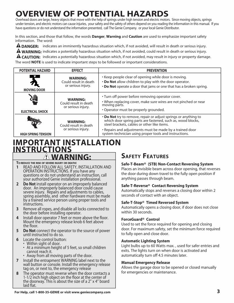
oVeRView of potential haZaRdSOverhead doors are large, heavy objects that move with the help of springs under high tension and electric motors . Since moving objects, springs under tension, and electric motors can cause injuries, your safety and the safety of others depend on you reading the information in this manual . If you have questions or do not understand the information presented, call The Genie Company . or your local Genie Distributor .
POTENTIAL HAZARD EFFECT PREVENTION
• Keep people clear of opening while door is moving.• Do Not allow children to play with the door operator .• Do Not operate a door that jams or one that has a broken spring .
MOVING DOOR
WARNING:Could result in death
or serious injury .
• Turn off power before removing operator cover.
• When replacing cover, make sure wires are not pinched or near moving parts .• Operator must be properly grounded.ELECTRICAL SHOCK• Do Not try to remove, repair or adjust springs or anything to which door spring parts are fastened, such as, wood blocks, steel brackets, cables or other like items .
• Repairs and adjustments must be made by a trained door system technician using proper tools and instructions .HIGH SPRING TENSION
WARNING:Could result in death
or serious injury .
WARNING:Could result in death
or serious injury .
In this section, and those that follow, the words Danger, Warning and Caution are used to emphasize important safety information . The word:
indicates an imminently hazardous situation which, if not avoided, will result in death or serious injury .
indicates a potentially hazardous situation which, if not avoided, could result in death or serious injury .
indicates a potentially hazardous situation which, if not avoided, may result in injury or property damage .
The word NOTE is used to indicate important steps to be followed or important considerations .
DANGER:
CAUTION:WARNING:
Safe-T-Beam® (STB) Non-Contact Reversing System Places an invisible beam across door opening, that reverses the door during down travel to the fully open position if anything passes through beam .
Safe-T-Reverse® Contact Reversing System Automatically stops and reverses a closing door within 2 seconds of contact with an object .
Safe-T-Stop® Timed Reversed System Automatically opens a closing door, if door does not close within 30 seconds .
ForceGuard® Control Used to set the force required for opening and closing door . For maximum safety, set the minimum force required to fully open and close door .
Automatic Lighting System Light bulbs up to 60 Watts max . , used for safer entries and exits . The lights turn on when door is activated and automatically turn off 4 .5 minutes later .
Manual Emergency Release Allows the garage door to be opened or closed manually for emergencies or maintenance .
IMPORTANT INSTALLATIONINSTRUCTIONS
1 READ AND FOLLOW ALL SAFETY, INSTALL ATION AND OPERATION INSTRUCTIONS . If you have any questions or do not understand an instruction, call your authorized Genie installation professional . 2 Do Not install operator on an improperly balanced door . An improperly balanced door could cause severe injury . Repairs and adjustments to cables, spring assembly, and other hardware must be made by a trained service person using proper tools and instructions . 3 Remove all ropes, and disable all locks connected to the door before installing operator . 4 Install door operator 7 feet or more above the floor . Mount the emergency release knob 6 feet above the floor . 5 Do Not connect the operator to the source of power until instructed to do so . 6 Locate the control button: • Within sight of door. • At a minimum height of 5 feet, so small children cannot reach it . • Away from all moving parts of the door. 7 Install the entrapment WARNING label next to the wall button or console . Install the emergency release tag on, or next to, the emergency release 8 The operator must reverse when the door contacts a 1-1/2 inch high object on the floor at the center of the doorway . This is about the size of a 2” x 4” board laid flat .
to ReduCe the RiSk of SeVeRe injuRy oR death: WARNING: Safety featuReS
4 For Help, call 1-800-35-GENIE or visit www.geniecompany.com
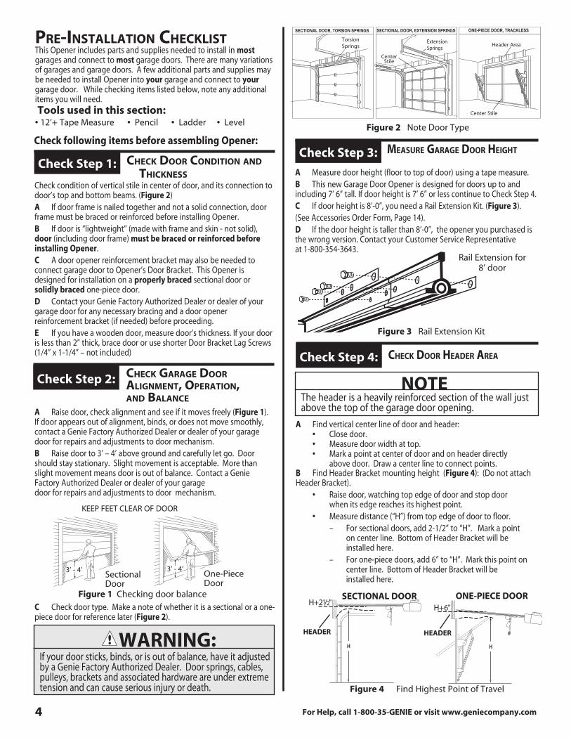
Figure 2 Note Door Type
SECTIONAL DOOR, TORSION SPRINGS SECTIONAL DOOR, EXTENSION SPRINGS ONE-PIECE DOOR, TRACKLESS
meaSuRe GaRaGe dooR heiGht
A Measure door height (floor to top of door) using a tape measure .B This new Garage Door Opener is designed for doors up to and including 7’ 6” tall . If door height is 7’ 6” or less continue to Check Step 4 . C If door height is 8’-0”, you need a Rail Extension Kit . (Figure 3) .(See Accessories Order Form, Page 14) .D If the door height is taller than 8’-0”, the opener you purchased is the wrong version . Contact your Customer Service Representative at 1-800-354-3643 .
Check Step 3:
pRe-inStallation CheCkliStThis Opener includes parts and supplies needed to install in most garages and connect to most garage doors . There are many variations of garages and garage doors . A few additional parts and supplies may be needed to install Opener into your garage and connect to your garage door . While checking items listed below, note any additional items you will need . Tools used in this section:• 12’+ Tape Measure • Pencil • Ladder • Level
Check following items before assembling Opener:
CheCk dooR Condition and
thiCkneSS Check Step 1:
CheCk GaRaGe dooR aliGnment, opeRation, and balanCe
Check Step 2:
WARNING:If your door sticks, binds, or is out of balance, have it adjusted by a Genie Factory Authorized Dealer . Door springs, cables, pulleys, brackets and associated hardware are under extreme tension and can cause serious injury or death .
KEEP FEET CLEAR OF DOOR
3’ - 4’Sectional Door
3’ - 4’
Figure 1 Checking door balance
One-Piece Door
Torsion Springs
Extension Springs
CenterStile
Center Stile
Header Area
Figure 3 Rail Extension Kit
Rail Extension for 8’ door
Check condition of vertical stile in center of door, and its connection to door’s top and bottom beams . (Figure 2)A If door frame is nailed together and not a solid connection, door frame must be braced or reinforced before installing Opener .B If door is “lightweight” (made with frame and skin - not solid), door (including door frame) must be braced or reinforced before installing Opener . C A door opener reinforcement bracket may also be needed to connect garage door to Opener’s Door Bracket . This Opener is designed for installation on a properly braced sectional door or solidly braced one-piece door . D Contact your Genie Factory Authorized Dealer or dealer of your garage door for any necessary bracing and a door opener reinforcement bracket (if needed) before proceeding .E If you have a wooden door, measure door’s thickness . If your door is less than 2” thick, brace door or use shorter Door Bracket Lag Screws (1/4” x 1-1/4” – not included)
A Raise door, check alignment and see if it moves freely (Figure 1) . If door appears out of alignment, binds, or does not move smoothly, contact a Genie Factory Authorized Dealer or dealer of your garage door for repairs and adjustments to door mechanism . B Raise door to 3’ – 4’ above ground and carefully let go . Door should stay stationary . Slight movement is acceptable . More than slight movement means door is out of balance . Contact a Genie Factory Authorized Dealer or dealer of your garage door for repairs and adjustments to door mechanism .
C Check door type . Make a note of whether it is a sectional or a one-piece door for reference later (Figure 2) .
B Find Header Bracket mounting height (Figure 4): (Do not attach Header Bracket) . • Raise door, watching top edge of door and stop door when its edge reaches its highest point . • Measure distance (“H”) from top edge of door to floor . – For sectional doors, add 2-1/2” to “H” . Mark a point on center line . Bottom of Header Bracket will be installed here . – For one-piece doors, add 6” to “H” . Mark this point on center line . Bottom of Header Bracket will be installed here .
CheCk dooR headeR aRea
A Find vertical center line of door and header: • Close door . • Measure door width at top . • Mark a point at center of door and on header directly above door . Draw a center line to connect points .
Check Step 4:
NOTEThe header is a heavily reinforced section of the wall just above the top of the garage door opening .
Figure 4 Find Highest Point of Travel
SECTIONAL DOOR ONE-PIECE DOOR
HEADER HEADER
C Check wall for a stud or a solid header at your mark: (If checking a finished wall, a stud finder may be helpful) . • If location is above Header, a 2” x 6” board must be screwed to studs beside your mark with at least two Lag Screws and Flat Washers (not provided) . • Transfer your mark to new mounting board .
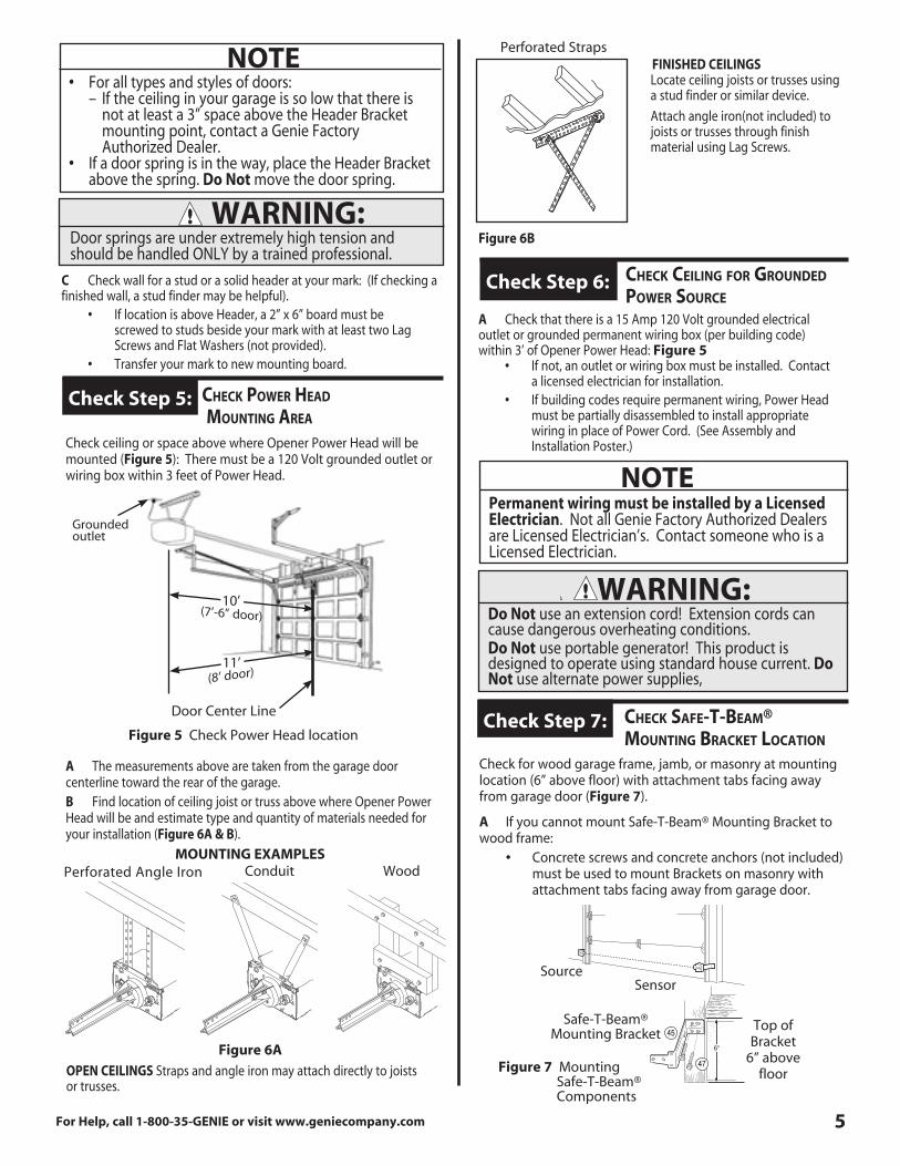
Check ceiling or space above where Opener Power Head will be mounted (Figure 5): There must be a 120 Volt grounded outlet or wiring box within 3 feet of Power Head .
A The measurements above are taken from the garage door centerline toward the rear of the garage .B Find location of ceiling joist or truss above where Opener Power Head will be and estimate type and quantity of materials needed for your installation (Figure 6A & B) .
For Help, call 1-800-35-GENIE or visit www.geniecompany.com 5
WARNING:Door springs are under extremely high tension and should be handled ONLY by a trained professional .
NOTE• For all types and styles of doors: – If the ceiling in your garage is so low that there is not at least a 3” space above the Header Bracket mounting point, contact a Genie Factory Authorized Dealer . • If a door spring is in the way, place the Header Bracket above the spring . Do Not move the door spring .
CheCk poweR head mountinG aRea Check Step 5:
Door Center Line
Figure 5 Check Power Head location
11’
Figure 6B
FINISHED CEILINGS Locate ceiling joists or trusses using a stud finder or similar device .
Attach angle iron(not included) to joists or trusses through finish material using Lag Screws .
MOUNTING EXAMPLES
55 11
30
30
55 11
30
Perforated Straps
ConduitPerforated Angle Iron Wood
CheCk CeilinG foR GRounded poweR SouRCe
Check Step 6:
NOTEPermanent wiring must be installed by a Licensed Electrician . Not all Genie Factory Authorized Dealers are Licensed Electrician’s . Contact someone who is a Licensed Electrician .
WARNING:Do Not use an extension cord! Extension cords can cause dangerous overheating conditions .Do Not use portable generator! This product is designed to operate using standard house current . Do Not use alternate power supplies,
A Check that there is a 15 Amp 120 Volt grounded electrical outlet or grounded permanent wiring box (per building code) within 3’ of Opener Power Head: Figure 5 • If not, an outlet or wiring box must be installed . Contact a licensed electrician for installation . • If building codes require permanent wiring, Power Head must be partially disassembled to install appropriate wiring in place of Power Cord . (See Assembly and Installation Poster .)
CheCk Safe-t-beam® mountinG bRaCket loCation Check Step 7:
Check for wood garage frame, jamb, or masonry at mounting location (6” above floor) with attachment tabs facing away from garage door (Figure 7) .
A If you cannot mount Safe-T-Beam® Mounting Bracket to wood frame: • Concrete screws and concrete anchors (not included) must be used to mount Brackets on masonry with attachment tabs facing away from garage door .
SourceSensor
Safe-T-Beam®Mounting Bracket
Top of Bracket
6” above floorFigure 7 Mounting
Safe-T-Beam® Components
Grounded outlet
10’(7’-6” door)
(8’ door)
Figure 6A
OPEN CEILINGS Straps and angle iron may attach directly to joists or trusses .
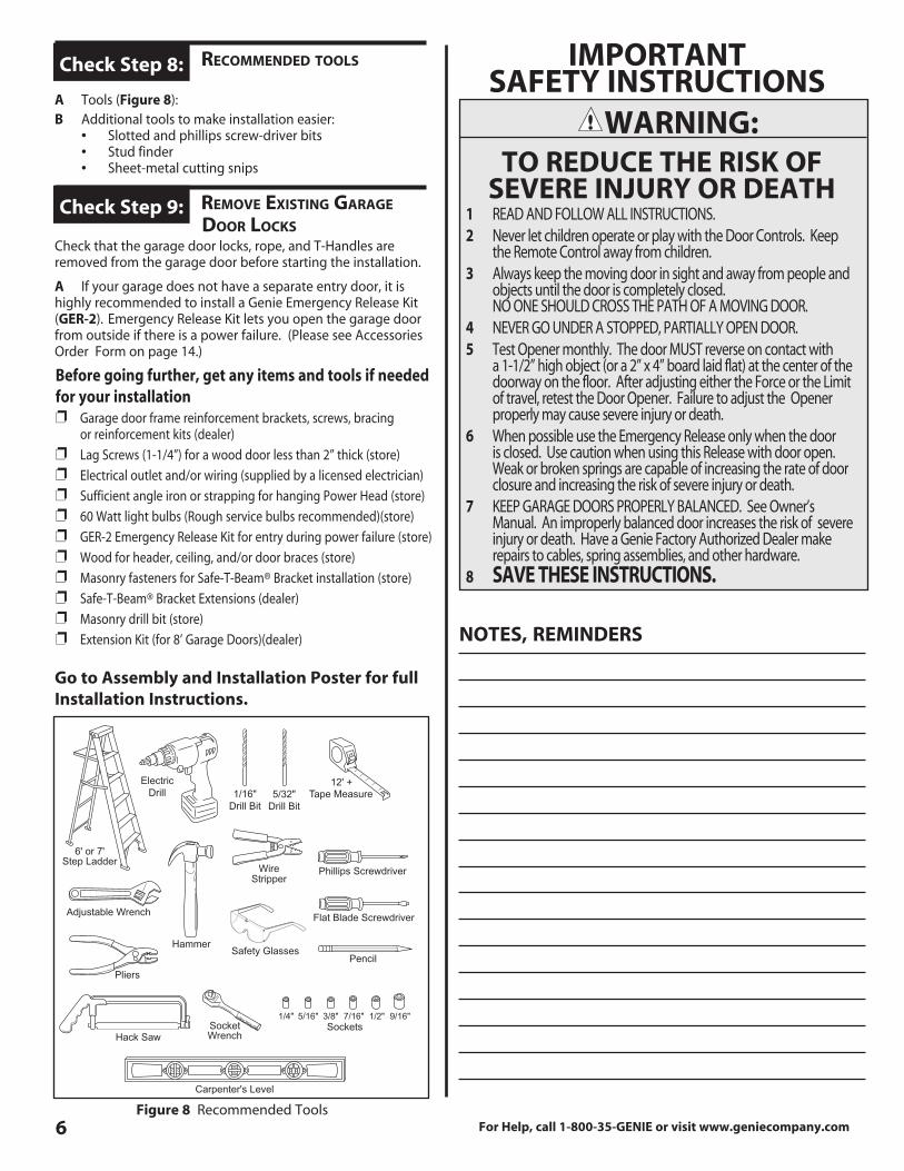
For Help, call 1-800-35-GENIE or visit www.geniecompany.com6Figure 8 Recommended Tools
Go to Assembly and Installation Poster for full Installation Instructions.
ReCommended toolS
A Tools (Figure 8):B Additional tools to make installation easier: • Slotted and phillips screw-driver bits • Stud finder • Sheet-metal cutting snips
Check Step 8:
D RemoVe exiStinG GaRaGe
dooR loCkS
Check that the garage door locks, rope, and T-Handles are removed from the garage door before starting the installation .
A If your garage does not have a separate entry door, it is highly recommended to install a Genie Emergency Release Kit (GER-2) . Emergency Release Kit lets you open the garage door from outside if there is a power failure . (Please see Accessories Order Form on page 14 .)
Check Step 9:
Before going further, get any items and tools if needed for your installationp Garage door frame reinforcement brackets, screws, bracing or reinforcement kits (dealer)
p Lag Screws (1-1/4”) for a wood door less than 2” thick (store)
p Electrical outlet and/or wiring (supplied by a licensed electrician)
p Sufficient angle iron or strapping for hanging Power Head (store)
p 60 Watt light bulbs (Rough service bulbs recommended)(store)
p GER-2 Emergency Release Kit for entry during power failure (store)
p Wood for header, ceiling, and/or door braces (store)
p Masonry fasteners for Safe-T-Beam® Bracket installation (store)
p Safe-T-Beam® Bracket Extensions (dealer)
p Masonry drill bit (store)
p Extension Kit (for 8’ Garage Doors)(dealer)
WARNING:TO REDUCE THE RISK OF
SEVERE INJURY OR DEATH
IMPORTANT SAFETY INSTRUCTIONS
1 READ AND FOLLOW ALL INSTRUCTIONS .2 Never let children operate or play with the Door Controls . Keep the Remote Control away from children .3 Always keep the moving door in sight and away from people and objects until the door is completely closed . NO ONE SHOULD CROSS THE PATH OF A MOVING DOOR .4 NEVER GO UNDER A STOPPED, PARTIALLY OPEN DOOR . 5 Test Opener monthly . The door MUST reverse on contact with a 1-1/2” high object (or a 2” x 4” board laid flat) at the center of the doorway on the floor . After adjusting either the Force or the Limit of travel, retest the Door Opener . Failure to adjust the Opener properly may cause severe injury or death .6 When possible use the Emergency Release only when the door is closed . Use caution when using this Release with door open . Weak or broken springs are capable of increasing the rate of door closure and increasing the risk of severe injury or death .7 KEEP GARAGE DOORS PROPERLY BALANCED . See Owner’s Manual . An improperly balanced door increases the risk of severe injury or death . Have a Genie Factory Authorized Dealer make repairs to cables, spring assemblies, and other hardware .8 SAVE THESE INSTRUCTIONS.
noteS, RemindeRS
For Help, call 1-800-35-GENIE or visit www.geniecompany.com 7
Ch adjuStinG limit SwitCheS and foRCe ContRolS Adjustment 1:
A CLOSE ADJUSTMENT • On front panel of Power Head find adjusting screw marked “CLOSE” (Figure MA-1) . • Gently turn screw counterclockwise until it stops . – Very little force is required to turn adjusting screw . • Press Wall Console to close garage door . – Observe if door stops at “CLOSE” limit switch . (Figure MA-2) . If door is fully closed—adjustment is finished . Go to “OPEN” Adjustment . – If door stops but is not fully closed, a . Measure distance between bottom of door and floor . b . Move “CLOSE” Limit Switch that same distance toward door . – If door stops and/or reverses before reaching the “CLOSE” Limit Switch a . Slightly increase CLOSE Force setting (clockwise) . – If door reverses after contacting floor, move Limit Switch toward Power Head . – If door fails to move, check Safe-T-Beam® System . See Troubleshooting Section, pages 10-11 .
• Tighten Limit Switch Set Screw . Do not over-tighten (strip) Limit Switch Set Screw .
B OPEN ADJUSTMENT • On front panel of Power Head find adjusting screw marked “OPEN” (Figure MA-1) . • Gently turn screw counterclockwise until it stops . – Very little force is required to turn adjusting screw . • Press Wall Console to open garage door . – Observe if door stops at “OPEN” limit switch . (Figure MA-2) . If door is fully open—adjustment is finished . – If door stops but is not fully open, a . Measure distance between bottom of door top of door opening . b . Move “OPEN” Limit Switch that same distance toward Power Head . – If door stops before reaching the “OPEN” Limit Switch a . Slightly increase OPEN Force setting (clockwise) . – If door fails to move, see Troubleshooting Section, pages 10-11 . • Tighten Limit Switch Set Screw . Do not over-tighten (strip) Limit Switch Set Screw .
C Run Door Opener • Cycle opener a few times to double check settings . Repeat adjustment steps as necessary .
WARNING:• A moving garage door can cause serious injury or death.• Keep the path clear.• Position the ladder to the side of the Power Head so it is clear of all moving parts of the Opener and the door .• Set the door Opener to use the minimum force needed to open the door .
NOTE• Little effort is required to turn the Force Adjusting Knobs .• If the door stops moving while opening or closing, adjust the Open Force or Close Force Controls slightly clockwise (to slightly increase the force) and retry the step .• The Open Force and Close Force Controls are to be set to the minimum force necessary to ensure the door smoothly opens and closes completely .• Ensure the Carriage Assembly is engaged and is between the two Limit Switches before operating the Opener .
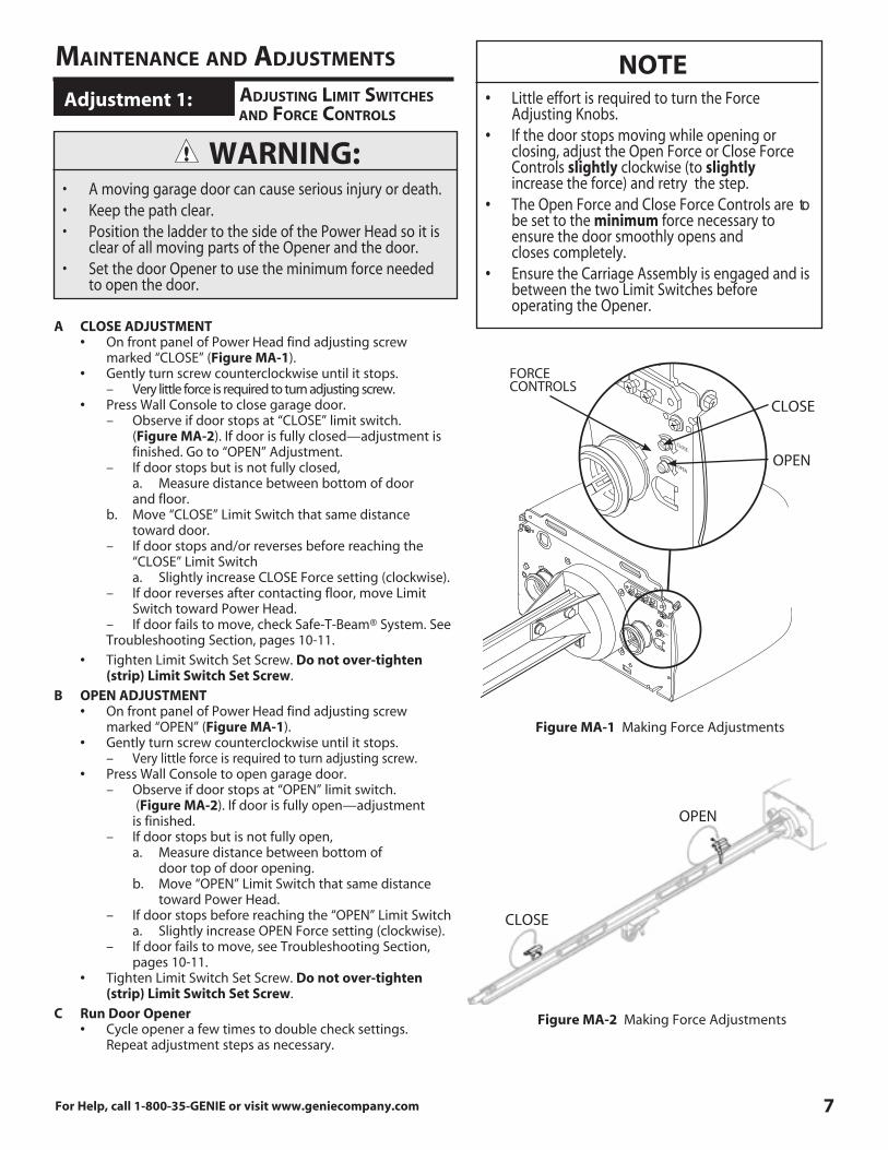
Figure MA-1 Making Force Adjustments
OPEN
CLOSE
OPEN
CLOSE
FORCECONTROLS
maintenanCe and adjuStmentS
Figure MA-2 Making Force Adjustments
OPEN
CLOSE
OPEN
CLOSE
8 For Help, call 1-800-35-GENIE or visit www.geniecompany.com
A To program one Button of a Remote Control (Figure MA-4):
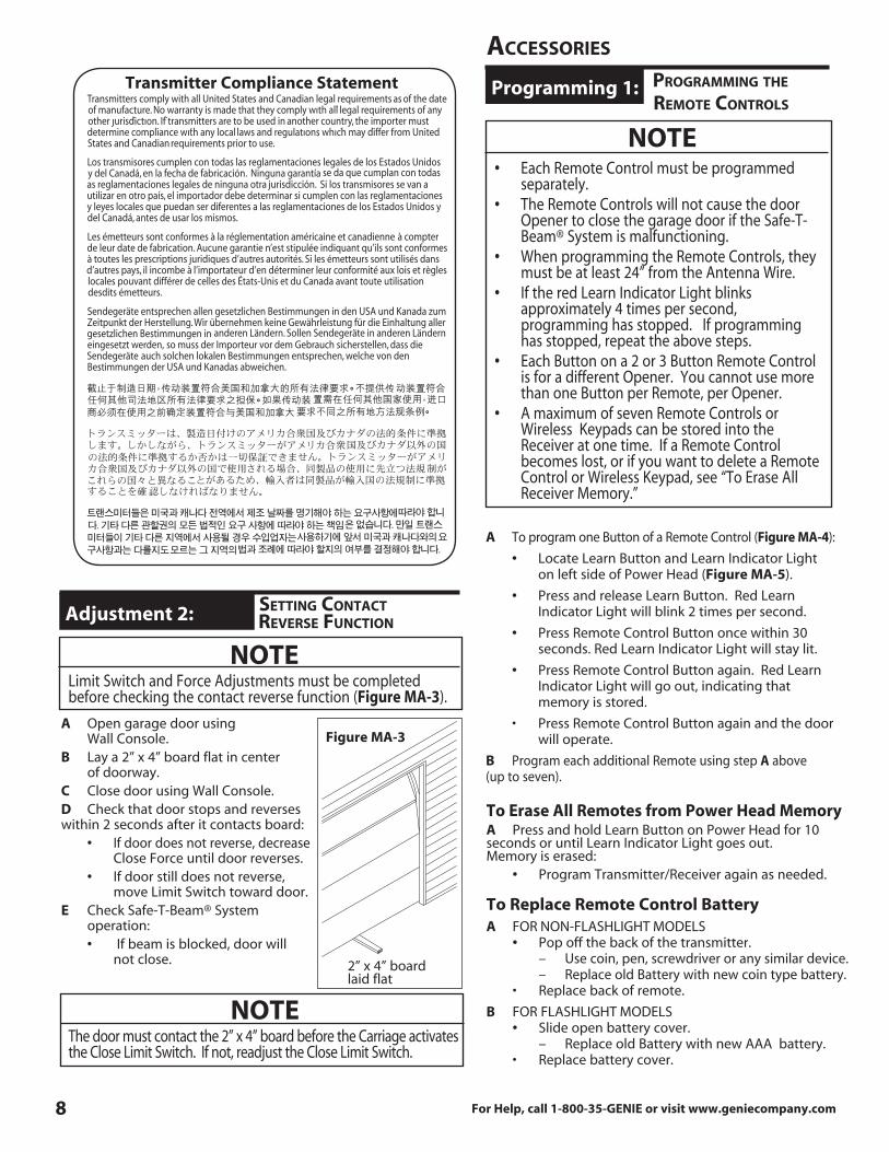
• Locate Learn Button and Learn Indicator Light on left side of Power Head (Figure MA-5) .
• Press and release Learn Button . Red Learn Indicator Light will blink 2 times per second .
• Press Remote Control Button once within 30 seconds . Red Learn Indicator Light will stay lit .
• Press Remote Control Button again . Red Learn Indicator Light will go out, indicating that memory is stored .
• Press Remote Control Button again and the door will operate .
B Program each additional Remote using step A above (up to seven) .
NOTE• Each Remote Control must be programmed separately .• The Remote Controls will not cause the door Opener to close the garage door if the Safe-T- Beam® System is malfunctioning .• When programming the Remote Controls, they must be at least 24” from the Antenna Wire .• If the red Learn Indicator Light blinks approximately 4 times per second, programming has stopped . If programming has stopped, repeat the above steps .• Each Button on a 2 or 3 Button Remote Control is for a different Opener . You cannot use more than one Button per Remote, per Opener .• A maximum of seven Remote Controls or Wireless Keypads can be stored into the Receiver at one time . If a Remote Control becomes lost, or if you want to delete a Remote Control or Wireless Keypad, see “To Erase All Receiver Memory .”
C pRoGRamminG the
Remote ContRolS Programming 1:
aCCeSSoRieS
To Erase All Remotes from Power Head MemoryA Press and hold Learn Button on Power Head for 10 seconds or until Learn Indicator Light goes out . Memory is erased: • Program Transmitter/Receiver again as needed .
To Replace Remote Control BatteryA FOR NON-FLASHLIGHT MODELS • Pop off the back of the transmitter . – Use coin, pen, screwdriver or any similar device . – Replace old Battery with new coin type battery . • Replace back of remote.
B FOR FLASHLIGHT MODELS • Slide open battery cover . – Replace old Battery with new AAA battery . • Replace battery cover.
A Open garage door using Wall Console .B Lay a 2” x 4” board flat in center of doorway .C Close door using Wall Console .D Check that door stops and reverses within 2 seconds after it contacts board: • If door does not reverse, decrease Close Force until door reverses . • If door still does not reverse, move Limit Switch toward door .E Check Safe-T-Beam® System operation: • If beam is blocked, door will not close .
NOTEThe door must contact the 2” x 4” board before the Carriage activates the Close Limit Switch . If not, readjust the Close Limit Switch .
Ch SettinG ContaCt ReVeRSe funCtion Adjustment 2:
NOTELimit Switch and Force Adjustments must be completed before checking the contact reverse function (Figure MA-3) .
2” x 4” boardlaid flat
Figure MA-3
Transmitter Compliance Statement
For Help, call 1-800-35-GENIE or visit www.geniecompany.com 9
Remote Control OperationA Press Button on Remote Control . Garage door will move .
B Press Button again . Garage door will stop: • The door automatically stops at the end of the open or close cycle .
C Press Button again . Garage door will reverse .
WARNING:A moving garage door may cause serious injury or death .• Keep people clear of opening while door is moving .• Do not allow children to play with the Remote Controls .If the Safety Reverse does not work properly:• Close the door and disconnect the Opener using the Emergency Release Cord .• Do not use the door Opener, Remote Controls, or Wireless Keypad .• Refer to the door and door Opener Owner’s Manuals before attempting any repairs .
1 2 3 4
Figure 13 Learn Code Button and Indicator LightFigure MA-5 Learn Code Button and Indicator Light
1 Button Compact Remotew/Docking Station
Figure MA-4 Genie Remote Controls
3 Button Compact Remotew/Docking Station
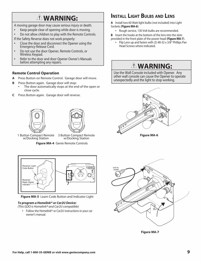
A Install two 60 Watt light bulbs (not included) into Light Sockets (Figure MA-6): • Rough service, 130 Volt bulbs are recommended .B Insert the hooks at the bottom of the lens into the slots provided in the front plate of the power head (Figure MA-7) . • Flip Lens up and fasten with (2) #8-32 x 3/8” Phillips Pan Head Screws where indicated .
Figure MA-7
Figure MA-6
inStall liGht bulbS and lenS
WARNING:Use the Wall Console included with Opener . Any other wall console can cause the Opener to operate unexpectedly and the light to stop working .
To program a Homelink® or Car2U Device:(This GDO is Homelink® and Car2U compatible) • Follow the Homelink® or Car2U instructions in your car owner’s manual .
(not to scale)

10 For Help, call 1-800-35-GENIE or visit www.geniecompany.com
A Monthly: • Door springs and door hardware: – Oil door roller, bearings, and hinges using silicone lubricant or light oil .
• Balance Door . – Close door . – Release Carriage Assembly from Rail Assembly by pulling the Emergency Release Knob towards the door . – Raise door manually 3’- 4’ and verify that door stays at that position . See Check Step 2 on page 4 .
– Reattach Carriage Assembly to Rail Assembly: a . Pull the Emergency Release Knob toward Power Head . b . Close door . • Contact Reverse Test. – Perform Adjustment 2 on page 8 .
NOTEWhen the door is 3’ - 4’ above the ground, the door should stay open . Slight movement is acceptable . If the door moves too much, contact a Genie Factory Authorized Dealer for service or call Customer Service at 1-800-35-GENIE.
WARNING:Do not operate door automatically or manually if springs are broken . Contact a Genie Factory Authorized Dealer for service or call Customer Service at 1-800-35-GENIE .
If the door fails to reverse on contact with the board, adjust the Close Force Control as specified in Set Limit Switches and Force Controls on page 7 & 8 . If the Opener still fails, contact a Genie Factory Authorized Dealer for service or call Customer Service at 1-800-35-GENIE .
NOTEUse ONLY Genie Lubricant (GLU-3) . Other lubricants may damage the Opener .
FCC AND IC CERTIFIEDAll devices comply with Part 15 of the FCC Rules . Operation is subject to the following two conditions: (1) this device may not cause harmful interference, and (2) this device must accept any interference received, includ-ing interference that may cause undesired operation .
Screw Drive Garage
Part No. GLU-3Door Opener Lubricant
GLU-3Lubricant
MAINTENANCE
B Yearly: • Wipe off old excess lubricant from Drive Screw . • Lubricate Drive Screw with Genie Lubricant (GLU-3)
C As needed • Replace lightbulbs. (See page 9)
Safe-T-Beam® System Self-Diagnostic Troubleshooting Source (Red LED) Sensor (Green LED) Possible Problem Solution
ON ON Normal operation None required
OFF OFF • Power Head not powered • Check breakers, fuses, plugs
• Wiring from Power Head bad • Check wiring for obvious shorts OFF ON
• Wiring to Source missing or bad • Check wiring • Power has been interrupted • Remove power and reapply
2 BLINKS, Pause • Beam not aligned • Check Source, Sensor alignment (Repeat) ON • Beam obstructed • Check for obstruction • Sensor defective • Contact Customer Service
2 BLINKS, Pause • Wire to Sensor missing or bad • Check wiring (Repeat) OFF • Sensor defective • Contact Customer Service
3 BLINKS, Pause • Sensor receiving interference • Determine source of interference (Repeat) ON • Check for interference from sun- light or a source unit on an adjacent door • Contact Customer Service
4 BLINKS, Pause • Source not sending pulses • Contact Customer Service (Repeat) ON • Source defective • Contact Customer Service
TROUBLESHOOTING
WARNING:

General Troubleshooting Problem What To Do
Opener does not run 1 . Check Lock switch on Wall Control (see Wall Console section on Installation Poster) . from Wall Control 2 . Check Power Source: • For Grounded Plug Connection . – Plug a lamp into the electrical outlet used for the door opener . a . If lamp lights, power source is good . b . If lamp does not light, check fuse or circuit breaker . • For Permanent Wiring Connection . – Check fuse or circuit breaker .
3 . Check connections (see Wall Console section on Installation Poster): • At Power Head Terminals and Wall Control .
Door Opener starts 1 . Check Wires to ensure that they are not cut (Stapes can cut insulation and short Wires) for no apparent reason Replace any shorting Staples and shorted Wires . 2 . Was Remote Control lost or stolen? If so, erase all Remote Control codes from Receiver’s memory and reprogram for remaining remote controls . (See Erase All Receiver Memory on page 11) . 3 . Ensure that no Buttons are stuck “pushed-in” on Wall Console or any Remote Controls .
Door starts down, then 1 . Check Close Limit Switch setting (page 7 and Installation Poster) . Adjust as needed . stops before it is 2 . Check Force Setting (page 7 & 8) . Adjust as needed . completely closed 3 . Check for shorted wires .
Door starts down, then 1 . If a new installation, check Door Arm position . stops and goes back up 2 . Check operation of Contact Reverse function . 3 . Check Safe-T-Beam® System for beam obstruction or misalignment of Lenses . 4 . Check Safe-T-Beam® System diagnostic code . 5 . Check Close Force adjustment (see Set Limit Switches and Force Controls on page 7 ) . Adjust as needed . 6 . Check garage door for binding .
Door will only run closed 1 . Check Open Limit Switch for a short circuit and for proper wiring . 2 . Check Open Force adjustment (see Set Limit Switches and Force Controls on page 7 & 8) . Adjust as needed . 3 . Check condition of garage door and door spring(s) . 4 . WARNING: If you suspect a problem with the garage door hardware or springs, contact a Genie Factory Authorized Dealer for service, or contact Customer Service at 1-800-35-GENIE . 5 . Check position of Lock Switch on Console .
Door will only run open 1 . Check Safe-T-Beam® System as detailed in the Safe-T-Beam® System Self-diagnostic Troubleshooting Chart (page 10) . 2 . Check Close Limit Switch for a short circuit and for proper wiring . 3 . Check Close Force adjustment (see Set Limit Switches and Force Controls on page 7 & 8) . Adjust as needed .
Lights will not turn off 1 . Disconnect Wires connecting Wall Console to Power Head (see “Wall Console Installation”- on Installation poster) . Check their condition and either replace or reconnect . 2 . Until a replacement Wall Console can be obtained, disconnect Wall Console and use only Remote Controls or Wireless Keypad to operate Opener . 3 . Check for non-compatible wall control .
Door starts up, but 1 . Check (ensure) that garage door and Opener are in good repair, properly lubricated, and properly stops before it is balanced as detailed in Maintenance Section . completely open 2 . WARNING: If you suspect a problem with the garage door hardware or springs, contact a Genie Factory Authorized Dealer for service, or contact Customer Service at 1-800-35-GENIE . 3 . Check Open Limit Switch for a short circuit and for proper wiring . 4 . Check Open Force adjustment (see Set Limit Switches and Force Controls on page 7 & 8) . Adjust as needed .
Operator runs, but door 1 . Ensure Carriage Assembly is engaged to Rail Drive Screw (see Install Carriage Assembly -INSTALLATION POSTER) . does not move 2 . Check Force adjustment (see Set Limit Switches and Force Controls on page 7) . Adjust as needed . 3 . Check that all sections of Rail Drive Screw are turning when Motor runs . If not: • Check condition (not cracked, split, or broken) and placement of Coupler. Replace as needed. • Check condition (not cracked, split, or broken) and placement of Collar and Clip. Replace them as needed .
Wall Console Vacation 1 . Ensure Carriage Assembly is in contact with Close Limit Switch . Lock function does 2 . Check when door is fully closed, that Carriage activates Close Limit Switch . If not, adjust position of Close not work Limit Switch (See page7) .
Noisy Operation 1 . Be sure all fasteners are tight . 2 . Check (ensure) that garage door and Opener are in good repair, properly lubricated, and properly balanced as described in Maintenance Section (page 10) .
11For Help, call 1-800-35-GENIE or visit www.geniecompany.com
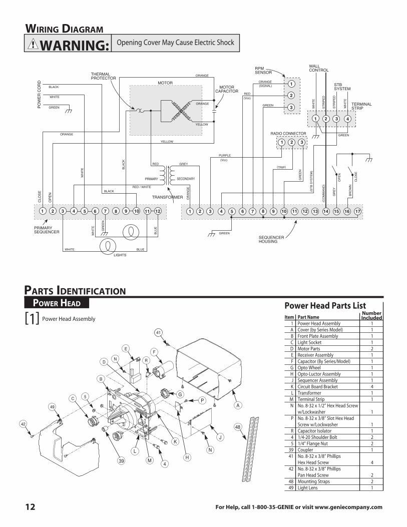
Opening Cover May Cause Electric Shock
wiRinG diaGRam
1 2 3 4 5 6 7 8 9 10 11 12 3 4 5 6 7 8 9 10 11 12 13 14 15 16 171 2
31
1
2
3
2
3 41 2
BLACK
ORANGE
ORANGE
ORANGE
ORANGE
CLO
SE
OPE
N
YELLOW
YELLOW
WHITE
WH
ITE
WH
ITE
WH
ITE
WH
ITE
STR
IPED
STR
IPED
BLACK
BLAC
K
PURPLE
GR
EEN
BLUE
BLU
E
RED / WHITE
RED
RED
GREY
GR
EY
BRO
WN
OR
ANG
E
GR
EEN
GREEN
GREEN
GREEN
OPE
N
CLO
SE
LIGHTS
WHITE
GREENPOW
ER C
OR
D
PRIMARYSEQUENCER
MOTOR
RPMSENSOR
WALL CONTROL
RADIO CONNECTOR
STB SYSTEM
TERMINAL STRIP
MOTORCAPACITOR
THERMAL PROTECTOR
PRIMARY SECONDARY
TRANSFORMER
SEQUENCER HOUSING
(Vcc)
(SIGNAL)
(Vcc)
(TRIP)
(STB
SYS
TEM
)
(CO
MM
AND
)
41
FE
N
B
5C
49
42
D R
39 4
L
M
K
HN
J
A
48
GP
Power Head Assembly[1]
paRtS identifiCation
Item Part Name 1 Power Head Assembly 1 A Cover (by Series Model) 1 B Front Plate Assembly 1 C Light Socket 1 D Motor Parts 2 E Receiver Assembly 1 F Capacitor (By Series/Model) 1 G Opto Wheel 1 H Opto-Luctor Assembly 1 J Sequencer Assembly 1 K Circuit Board Bracket 4 L Transformer 1 M Terminal Strip 1 N No . 8-32 x 1/2” Hex Head Screw w/Lockwasher 1 P No . 8-32 x 3/8” Slot Hex Head Screw w/Lockwasher 1 R Capacitor Isolator 1 4 1/4-20 Shoulder Bolt 2 5 1/4” Flange Nut 2 39 Coupler 1 41 No . 8-32 x 3/8” Phillips Hex Head Screw 4 42 No . 8-32 x 3/8” Phillips Pan Head Screw 2 48 Mounting Straps 2 49 Light Lens 1
Power Head Parts List poweR headNumberIncluded
WARNING:
12 For Help, call 1-800-35-GENIE or visit www.geniecompany.com
For Help, call 1-800-35-GENIE or visit www.geniecompany.com 13
15
9
7
12
166
1
44
229
2224
28
26
23
910
25
17
18
27
46
15
4
39
5
47
25
24
8
11
3A
3B
3C
13
20
21
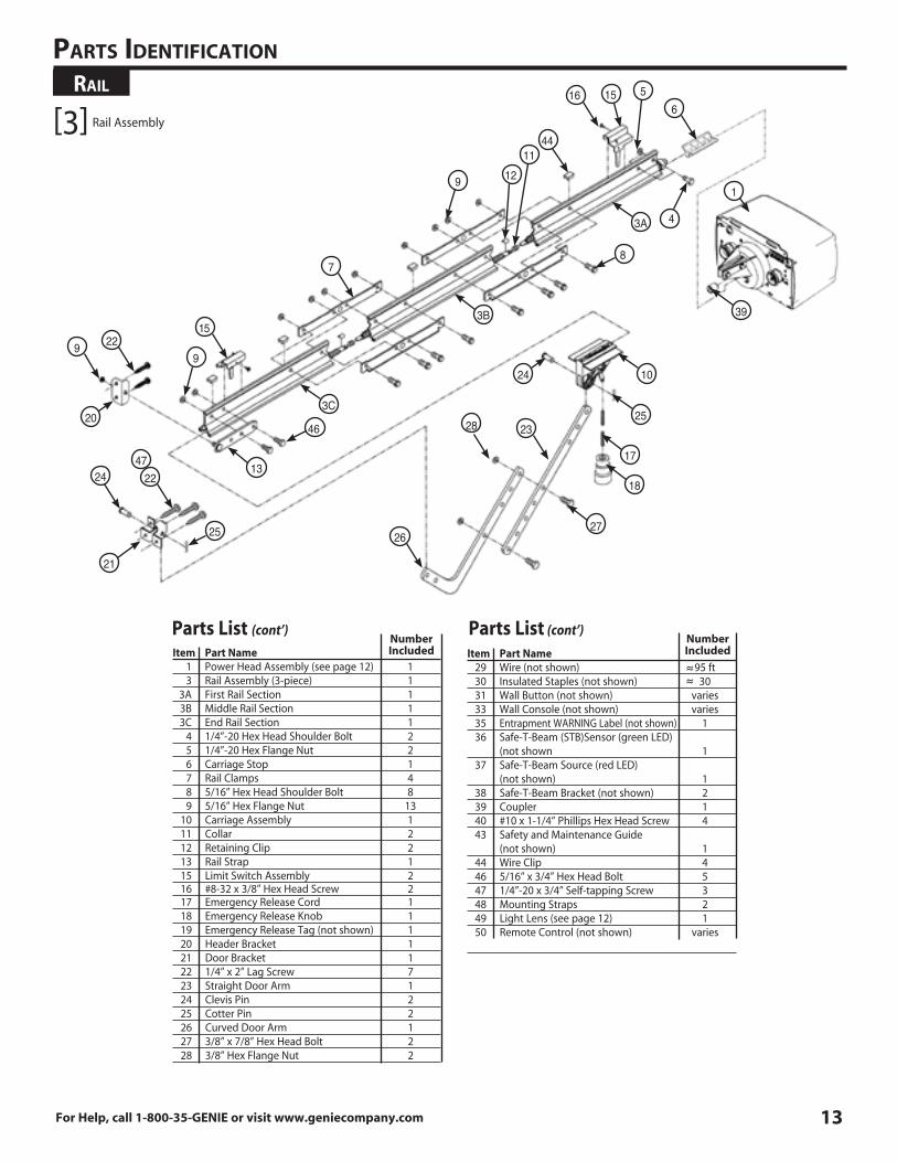
Rail
paRtS identifiCation
Item Part Name 1 Power Head Assembly (see page 12) 1 3 Rail Assembly (3-piece) 1 3A First Rail Section 1 3B Middle Rail Section 1 3C End Rail Section 1 4 1/4”-20 Hex Head Shoulder Bolt 2 5 1/4”-20 Hex Flange Nut 2 6 Carriage Stop 1 7 Rail Clamps 4 8 5/16” Hex Head Shoulder Bolt 8 9 5/16” Hex Flange Nut 13 10 Carriage Assembly 1 11 Collar 2 12 Retaining Clip 2 13 Rail Strap 1 15 Limit Switch Assembly 2 16 #8-32 x 3/8” Hex Head Screw 2 17 Emergency Release Cord 1 18 Emergency Release Knob 1 19 Emergency Release Tag (not shown) 1 20 Header Bracket 1 21 Door Bracket 1 22 1/4” x 2” Lag Screw 7 23 Straight Door Arm 1 24 Clevis Pin 2 25 Cotter Pin 2 26 Curved Door Arm 1 27 3/8” x 7/8” Hex Head Bolt 2 28 3/8” Hex Flange Nut 2
Parts List (cont’)Number Included Item Part Name
29 Wire (not shown) 95 ft 30 Insulated Staples (not shown) 30 31 Wall Button (not shown) varies 33 Wall Console (not shown) varies 35 Entrapment WARNING Label (not shown) 1 36 Safe-T-Beam (STB)Sensor (green LED) (not shown 1 37 Safe-T-Beam Source (red LED) (not shown) 1 38 Safe-T-Beam Bracket (not shown) 2 39 Coupler 1 40 #10 x 1-1/4” Phillips Hex Head Screw 4 43 Safety and Maintenance Guide (not shown) 1 44 Wire Clip 4 46 5/16” x 3/4” Hex Head Bolt 5 47 1/4”-20 x 3/4” Self-tapping Screw 3 48 Mounting Straps 2 49 Light Lens (see page 12) 1 50 Remote Control (not shown) varies
Number Included
~~
Parts List (cont’)
Rail Assembly[3]
~~
14 For Help, call 1-800-35-GENIE or visit www.geniecompany.com
®
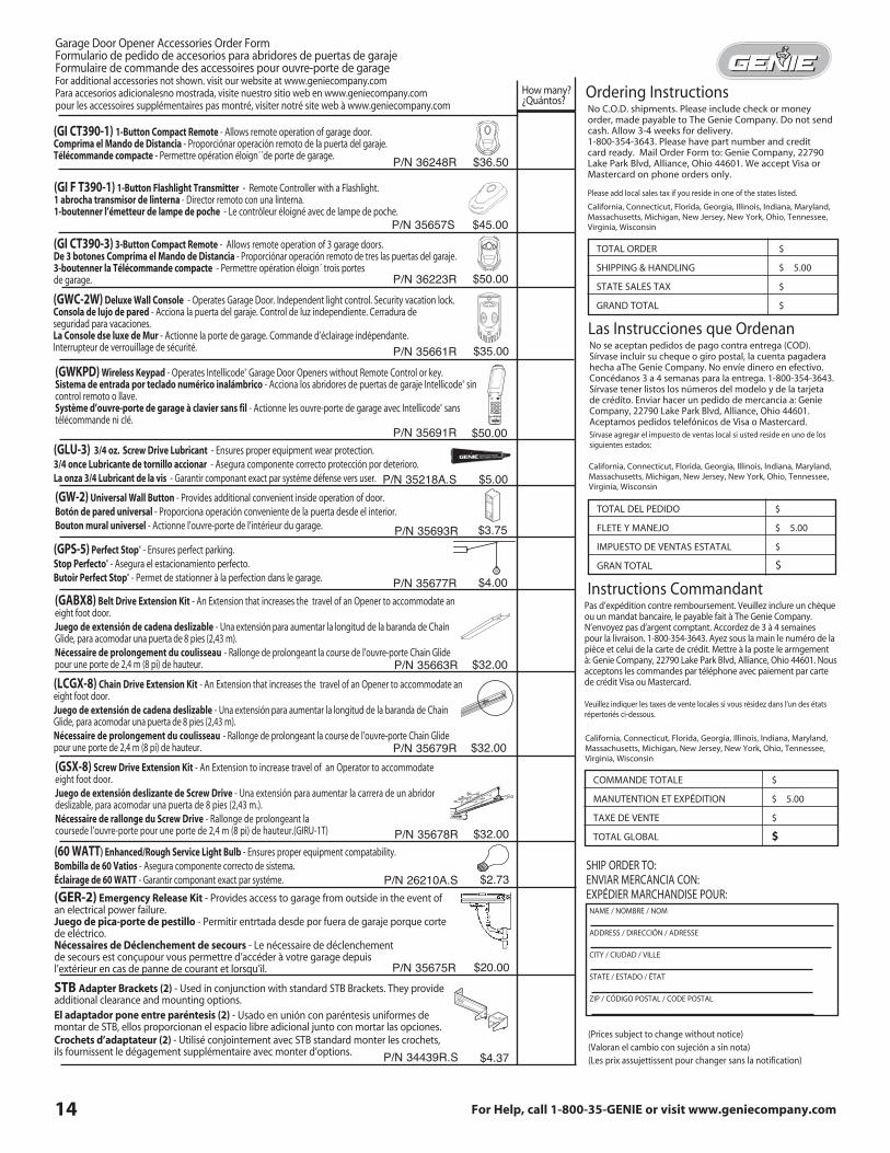
No C .O .D . shipments . Please include check or money order, made payable to The Genie Company . Do not send cash . Allow 3-4 weeks for delivery . 1-800-354-3643 . Please have part number and credit card ready . Mail Order Form to: Genie Company, 22790 Lake Park Blvd, Alliance, Ohio 44601 . We accept Visa or Mastercard on phone orders only .
Please add local sales tax if you reside in one of the states listed .
California, Connecticut, Florida, Georgia, Illinois, Indiana, Maryland, Massachusetts, Michigan, New Jersey, New York, Ohio, Tennessee, Virginia, Wisconsin
TOTAL ORDER $
SHIPPING & HANDLING $ 5 .00
STATE SALES TAX $
GRAND TOTAL $
Pas d’expédition contre remboursement . Veuillez inclure un chèque ou un mandat bancaire, le payable fait à The Genie Company . N’envoyez pas d’argent comptant . Accordez de 3 à 4 semaines pour la livraison . 1-800-354-3643 . Ayez sous la main le numéro de la pièce et celui de la carte de crédit . Mettre à la poste le arrngement à: Genie Company, 22790 Lake Park Blvd, Alliance, Ohio 44601 . Nous acceptons les commandes par téléphone avec paiement par carte de crédit Visa ou Mastercard .
Veuillez indiquer les taxes de vente locales si vous résidez dans l’un des états répertoriés ci-dessous .
COMMANDE TOTALE $
MANUTENTION ET EXPÉDITION $ 5 .00
TAXE DE VENTE $
TOTAL GLOBAL $
No se aceptan pedidos de pago contra entrega (COD) . Sírvase incluir su cheque o giro postal, la cuenta pagadera hecha aThe Genie Company . No envíe dinero en efectivo . Concédanos 3 a 4 semanas para la entrega . 1-800-354-3643 . Sírvase tener listos los números del modelo y de la tarjeta de crédito . Enviar hacer un pedido de mercancia a: Genie Company, 22790 Lake Park Blvd, Alliance, Ohio 44601 .Aceptamos pedidos telefónicos de Visa o Mastercard .Sírvase agregar el impuesto de ventas local si usted reside en uno de los siguientes estados:
Ordering Instructions
Las Instrucciones que Ordenan
Instructions Commandant
Screw Drive GarageDoor Opener Lubricant
(GI CT390-1) 1-Button Compact Remote - Allows remote operation of garage door . Comprima el Mando de Distancia - Proporciónar operación remoto de la puerta del garaje . Télécommande compacte - Permettre opération éloign´´de porte de garage .
(GI CT390-3) 3-Button Compact Remote - Allows remote operation of 3 garage doors . De 3 botones Comprima el Mando de Distancia - Proporciónar operación remoto de tres las puertas del garaje . 3-boutenner la Télécommande compacte - Permettre opération éloign´ trois portes de garage .
(GWKPD) Wireless Keypad - Operates Intellicode® Garage Door Openers without Remote Control or key . Sistema de entrada por teclado numérico inalámbrico - Acciona los abridores de puertas de garaje Intellicode® sin control remoto o llave . Système d’ouvre-porte de garage à clavier sans fil - Actionne les ouvre-porte de garage avec Intellicode® sans télécommande ni clé .
(GLU-3) 3/4 oz. Screw Drive Lubricant - Ensures proper equipment wear protection .3/4 once Lubricante de tornillo accionar - Asegura componente correcto protección por deterioro .La onza 3/4 Lubricant de la vis - Garantir componant exact par systéme défense vers user .
(GW-2) Universal Wall Button - Provides additional convenient inside operation of door .Botón de pared universal - Proporciona operación conveniente de la puerta desde el interior .Bouton mural universel - Actionne l’ouvre-porte de l’intérieur du garage .
(GPS-5) Perfect Stop® - Ensures perfect parking .Stop Perfecto® - Asegura el estacionamiento perfecto .Butoir Perfect Stop® - Permet de stationner à la perfection dans le garage .
(LCGX-8) Chain Drive Extension Kit - An Extension that increases the travel of an Opener to accommodate an eight foot door . Juego de extensión de cadena deslizable - Una extensión para aumentar la longitud de la baranda de Chain Glide, para acomodar una puerta de 8 pies (2,43 m) .Nécessaire de prolongement du coulisseau - Rallonge de prolongeant la course de l’ouvre-porte Chain Glide pour une porte de 2,4 m (8 pi) de hauteur .
(60 WATT) Enhanced/Rough Service Light Bulb - Ensures proper equipment compatability .Bombilla de 60 Vatios - Asegura componente correcto de sistema .éclairage de 60 WATT - Garantir componant exact par systéme .
(GER-2) Emergency Release Kit - Provides access to garage from outside in the event of an electrical power failure . Juego de pica-porte de pestillo - Permitir entrtada desde por fuera de garaje porque corte de eléctrico . Nécessaires de Déclenchement de secours - Le nécessaire de déclenchement de secours est conçupour vous permettre d’accéder à votre garage depuis l’extérieur en cas de panne de courant et lorsqu’il .
STB Adapter Brackets (2) - Used in conjunction with standard STB Brackets . They provide additional clearance and mounting options .El adaptador pone entre paréntesis (2) - Usado en unión con paréntesis uniformes de montar de STB, ellos proporcionan el espacio libre adicional junto con mortar las opciones . Crochets d’adaptateur (2) - Utilisé conjointement avec STB standard monter les crochets, ils fournissent le dégagement supplémentaire avec monter d’options .
(GSX-8) Screw Drive Extension Kit - An Extension to increase travel of an Operator to accommodate eight foot door .Juego de extensión deslizante de Screw Drive - Una extensión para aumentar la carrera de un abridor deslizable, para acomodar una puerta de 8 pies (2,43 m .) .Nécessaire de rallonge du Screw Drive - Rallonge de prolongeant la coursede l’ouvre-porte pour une porte de 2,4 m (8 pi) de hauteur .(GIRU-1T)
SHIP ORDER TO: ENVIAR MERCANCIA CON: EXPÉDIER MARCHANDISE POUR:
NAME / NOMBRE / NOM
ADDRESS / DIRECCIóN / ADRESSE
CITY / CIUDAD / VILLE
STATE / ESTADO / ÉTAT
ZIP / CóDIGO POSTAL / CODE POSTAL
California, Connecticut, Florida, Georgia, Illinois, Indiana, Maryland, Massachusetts, Michigan, New Jersey, New York, Ohio, Tennessee, Virginia, Wisconsin
California, Connecticut, Florida, Georgia, Illinois, Indiana, Maryland, Massachusetts, Michigan, New Jersey, New York, Ohio, Tennessee, Virginia, Wisconsin
How many?¿Quántos?
$36.50
$50.00
$35.00
$50.00
$5.00
$3.75
$4.00
$32.00
$32.00
$2.73
$20.00
$4.37
P/N 36248R
P/N 36223R
P/N 35661R
P/N 35691R
P/N 35218A.S
P/N 35693R
P/N 35677R
P/N 35679R
P/N 35678R
(GWC-2W) Deluxe Wall Console - Operates Garage Door . Independent light control . Security vacation lock . Consola de lujo de pared - Acciona la puerta del garaje . Control de luz independiente . Cerradura de seguridad para vacaciones . La Console dse luxe de Mur - Actionne la porte de garage . Commande d’éclairage indépendante . Interrupteur de verrouillage de sécurité .
P/N 26210A.S
P/N 35675R
(Prices subject to change without notice) (Valoran el cambio con sujeción a sin nota) (Les prix assujettissent pour changer sans la notification)P/N 34439R.S
(GABX8) Belt Drive Extension Kit - An Extension that increases the travel of an Opener to accommodate an eight foot door . Juego de extensión de cadena deslizable - Una extensión para aumentar la longitud de la baranda de Chain Glide, para acomodar una puerta de 8 pies (2,43 m) .Nécessaire de prolongement du coulisseau - Rallonge de prolongeant la course de l’ouvre-porte Chain Glide pour une porte de 2,4 m (8 pi) de hauteur . $32.00P/N 35663R
Garage Door Opener Accessories Order FormFormulario de pedido de accesorios para abridores de puertas de garaje Formulaire de commande des accessoires pour ouvre-porte de garageFor additional accessories not shown . visit our website at www .geniecompany .comPara accesorios adicionalesno mostrada, visite nuestro sitio web en www .geniecompany .compour les accessoires supplémentaires pas montré, visiter notré site web à www .geniecompany .com
TOTAL DEL PEDIDO $
FLETE Y MANEJO $ 5 .00
IMPUESTO DE VENTAS ESTATAL $
GRAN TOTAL $
$45.00P/N 35657S
(GI F T390-1) 1-Button Flashlight Transmitter - Remote Controller with a Flashlight . 1 abrocha transmisor de linterna - Director remoto con una linterna . 1-boutenner l’émetteur de lampe de poche - Le contrôleur éloigné avec de lampe de poche .