Embed Size (px)
Citation preview

9th Annual North American Waste to Energy Conference ASME 2001
Operation and Performance of a Fluidized Bed Boiler
Firing Municipal Refuse Derived Fuel
ABSTRACT
in Ravenna, Italy
Michael L. Murphy Energy Products of Idaho
In early 1998, the City of Ravenna, Italy, commissioned a fluid bed boiler/waste-to-energy system to combust approximately 50,000 tonnes per year of processed municipal waste and generate electrical power. Much of the fuel preparation and processing equipment was already in place and the primary focus of this project was to implement an environmentally acceptable energy conversion process compatible with the 6.0tonnes per hour of fuel being processed. The fluid bed boiler system being provided incorporates state of the art environmental controls for abatement of all pollutants, including products of incomplete combustion (PIC's), NOx, acid gases, and particulates. The project delivers an average of 70,000 pounds per hour of steam to generate approximately 7 MW of electricity.
FLUIDIZED BED TECHNOLOGY
To date, only a handful offluid beds, either BFB or CFB, utilize RDF as a feed stock and only a portion of these systems feed 100 percent RDF fuel. The cause lies not so much in the fluid bed technology itself, but more so from the difficulties encountered in generating a manageable, homogeneous fuel mixture from a widely varying source and supply as typifies most municipal waste streams.
Fluid bed technology provides some well documented and widely recognized advantages to the combustion of solid fuels, especially lower quality, higher moisture fuels. In a bubbling fluid bed, a layer of sand, usuaIly around one and one-half to two feet in depth, is suspended in place by an upward flowing stream of fluidizing air.
At velocities of five to seven feet per second, this air/gas velocity creates a boilinglbubbling turbulence within the bed, causing it to behave in much the same manner as a pot of boiling water. Once this sand is heated to an optimum temperature, solid fuel introduced into it will almost immediately combust and bum to completion. The turbulence of the bed creates an enhanced combustion environment where the fuel particle is completely consumed in a matter of minutes. As the fuel particle bums, the abrasive action of the sand etches away any layer of ash from the surface, thereby exposing fresh fuel to the surrounding combustion air.
57

The motion developed from the fluidization enables the bed material to mix and distribute gases, fuel and temperature uniformly throughout the entire volume. The high turbulence and enhanced mixing enables the fluid bed to achieve an optimum combustion environment while operating at fairly moderate temperatures, 1400-1700 of. These lower temperatures minimize NOx formation resulting from "burning" of the nitrogen in the air and also reduce the furnace slagging resulting from high ash, content in the fuel.
PROCESS DESCRIPTION
The fuel characteristics of the waste material for this facility reflect a fairly good quality fuel in comparison to other waste streams. The fuel mixture is comprised of two waste streams, refuse derived fuel (RDF) and RSA, a source-specific waste stream composed primarily of cardboard, paper, wood and plastic.
The blended fuel for the design conditions has the following characteristics:
Component
C
H2 N2 O2 S Ash CI Moisture LHV
% Wt., Dry
55.7 4.6 0.7 17.8
0.5 20.0 0.7 15.8-25% 14.6 MJIKg - 16.7 MJIKg
Performance requirements specify the unit to operate with all acceptable steam conditions and permit/emission requirements over a range of three to six tonnes per hour of fuel at heating values ranging from 14.6 to 16.7 MJIKg.
In addition to the above chemical properties of the waste, the particle size is not more than four inches in any dimension, with 90 percent below three inches but not more than 10 percent below quarter-inch in size. The material is substantially free of metal content, especially metal wire of any size. The processing of the waste incorporates material shredding to size, followed by magnetic separation. The final waste stream is compressed through a roller mill/punched grate to create a relatively "densified" fuel stream.
The combustor is also designed to receive up to 1 0 percent of the furnace energy input as ten-pound boxes (16" x 16" x 24" dimension) of contaminated medical wastes.
Feedwater is provided at 125°C (25rF). The design criteria results in performance conditions ranging from 40,643 pounds per hour steam to 73,300 pounds per hour steam at 595 psia and 716°F.
58

The combustor, boiler, and gas clean up equipment are required to perform at a range of flue gas flowrate between 75,000 and 148, 100 pounds per hour.
Under nounal design/operating conditions, a bubbling fluidized bed operating over such a perfOlmance level would generate widely varied excess air levels and furnace temperatures. Typically, as capacity is reduced in turndown mode, air flows are maintained and furnace temperatures are allowed to drop. In this design, however, permit specifications have mandated a minimum 6% O2, wet volume, at all operating conditions and a furnace temperature of at least 8500 C.
Emission Requirements
This system is designed to maintain some of the most rigorous emission limits imposed on any wasteto-energy system of this kind in the world. The required levels are defined in the accompanying table.
Environmental Permit Conditions
Particulate SOx NOx HCI HF+HBr HCN PCB + PCN + PCT CO PAR PCDD _ PCDF (TEF) VOC Total Metals As, Cr, Co Cd, Hg, TI Sb, CN, Cr, Mn, Pcl, Pb, Pt, Cu, Sn, V
(I)Corrected to 11 % 02. vol. dry
PERFORMANCE TESTING
10 mgfNm3 (1) 100 200
10 2 0.5 0. 1 50 0. 1 0. 1 ngfNm3 10 0.6 0.5 0.05
0.5
The perf 01 mance and emission testing was conducted on February 25,2000. During the perfOlll1ance testing, the system was operating at the conditions outlined in the accompanying Table 1. For comparison, the design criteria is also included in this same table. In both cases, for analytical purposes, the design fuel analysis was assumed.
59

fuel moisture %, wet basis
XSAir
Fuel Input kglhr Ib/hr 8,000
Limestone feed kglhr Ib/hr 234
Steam flow kglhr Ib/hr 32,906
Steam T& pressure C/ barg F/ psia 384/ 38.8
Feedwater T C F 142
Combustor C F 893
25
33
Performance Test
25.8
48
17,643 7,777 17, 145
5 17 200 440
72,545 32,500 7 1,650
724/ 578 392/ 38.8 738/577
289 123 253
1640 900 1652
In the first series of testing, there was some problem in the results of the testing for dioxins. The measured levels, as shown, of 0.37 ngINm3, were well in excess of the permitted limits of 0. 1 ngINm3. Because of the minimal levels of all other products of combustion, it was believed that a problem had occurred in the operation or testing during these samples. After some review, it was concluded that two simultaneous conditions had occurred, namely the activated carbon injection system was operating with a plugged infeed and was not injecting any carbon into the flue gas scrubber during the test. Second, a mechanical failure of the damper in the baghouse bypass duct allowed a small, and undetermined, amount of bypass around the baghouse and flue gas treatment equipment. Both of these items were discovered and remedied after the first series of tests. A second test to measure the dioxins was conducted on March 16th. Those results are also included herein and show dioxin limits to be well within the required limits. In fact, inlet levels to the gas treatment system were measured at 0.27 ngINm3 (TEQ) as compared to the 0.034 ngINm3 outlet levels, indicating a reduction of over 87% in these levels through the flue gas treatment system.
In review of the emission results, it is apparent that the actual operating results are well below requirements in virtually every category. The NOx levels are reported to be within the expected requirements as shown, but in actuality, these levels are achieved using SNCR injection of aqueous ammonia in the combustor at only about 30% of the feedrate predicted in the design basis. Without knowing the uncontrolled NOX levels, the actual NH3 to NOx ratio is undeter mined, however, the data is clearly indicating that either the uncontrolled NOx levels are below the 360 mgINm3 predicted or the SNCR effectiveness is much better than anticipated, or both. The extremely low levels of all acid gases is not unexpected, given the conservatism in the equipment design and selection, utilizing limestone in the fluidized bed, lime slurry injection into the dry scrubber and a caustic spray scrubber in the exhaust stream. Further evaluation of the emissions ahead of the caustic spray scrubber would provide better insight into the actual need for this portion of the equipment in the FGT system.
60

Fuel Metering
Bin
•
SNCR
Overfire Air
FD Fan
Economizer
Fluid Bed Combustor
Bed Recycle System
Boiler
Venturi Reactor
Baghouse
Figure 1. Process Flow Schematic
61
.'
Wet Scrubber
. ..
Cyclone
I , I
Demister
ID Fan Stack
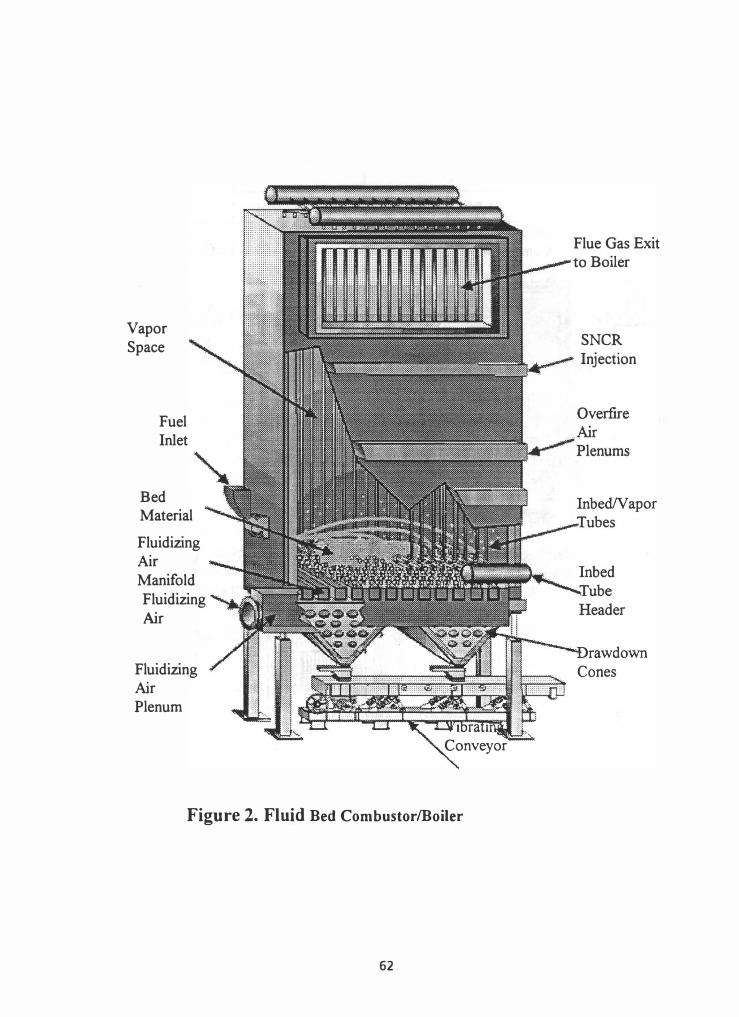
Vapor Space
Fuel Inlet
Bed Material
Fluidizing Air Manifold Fluidizing Air
Fluidizing Air Plenum
Figure 2. Fluid Bed CombustorlBoiler
62
Flue Gas Exit
SNCR Injection

Figure 3. Ravenna, Italy WTE Facility
Figure 4. Ravenna, Italy WTE Facility
63