Embed Size (px)
Citation preview

Model V-Bar Operation & Maintenance Manual
112.4
gal/min
E MCO
EM
CO
EMCO
EM
CO
EMCO
FLOW
Engineering Measurements Company303.651.0550 • 303.678.7152 Faxsales@emcofl ow.com
V-Bar-600/60SV-Bar-700V-Bar-800/80SV-Bar-910/960

- 3-
V - BAR™ INSTALLATION AND OPERATION MANUAL TABLE OF CONTENTS
Pressure and Temperature Transmitter Wiring..............................38 110 VAC Power and Signal Wiring ...............................................39 Analog Output (JP1 installed or no jumpers)...........................39 Simultaneous Pulse and Analog Output (JP1 installed) ...........39 Pulse Output Only (JP2 installed) ............................................39 Remote Wiring ..............................................................................40
Section 5–EZ Logic Programming ................................................41EZ Logic User Interface.....................................................................41Interface Map .....................................................................................42Keypad Activation..............................................................................43Movement Through Interface ............................................................43Altering Real Number Data ...............................................................44Altering Preset Data...........................................................................45Display menu .....................................................................................46 Flowrate.........................................................................................46 Totalized Flow...............................................................................46 Bar Graph......................................................................................46 Error Code.....................................................................................46Accessing Programming Submenus ..................................................46Confi gure Group ................................................................................47 Basic Menu Flow Unit..................................................................................47 Totalizer Unit............................................................................47 Maximum Flow ........................................................................47 Minimum Flow.........................................................................47 M-Factor...................................................................................47 Noise Level...............................................................................48 Output Menu Analog Output ..........................................................................48 Output Zero Time .....................................................................48 Frequency/Pulse Output Setup .................................................48 Scaled Frequency Output .........................................................49 Vortex Frequency Output .........................................................49 Direct Frequency Output ..........................................................49 Pulse - .......................................................................................50 Pulse + ......................................................................................50 Transition..................................................................................50 Fluid Menu....................................................................................51 Fluid Density ............................................................................51 Reference Density ....................................................................51 Density Range ..........................................................................51 Fluid Viscosity..........................................................................51 Fluid Temperature ....................................................................51 Sensor Menu Size ...........................................................................................51 Calibration Factor.....................................................................51 Serial.........................................................................................51 Tag Number..............................................................................51Diagnose Group .................................................................................51 Reset Menu Totalizer Reset ..........................................................................51 Set Defaults ..............................................................................52 Programmed Defaults...............................................................52 Service Menu ................................................................................52 Substitute Frequency ................................................................52 Simulated Analog Output .........................................................52 Simulated Frequency Output....................................................52 Input Signal Amplitude ............................................................53 Vortex Frequency......................................................................53 4 mA Calibration Value ............................................................53 20 mA Calibration Value ..........................................................53 Software Revision ....................................................................53 Self Diagnostics........................................................................53
Section 1 Product Introduction ........................................................5Principle of Operation..........................................................................5Features ................................................................................................5 V–Bar 600 Series ............................................................................6 V–Bar 700 Series ............................................................................6 V–Bar 800 Series ............................................................................6 V–Bar 900 Series ............................................................................6
Section 2 Inspection ..........................................................................7Equipment ............................................................................................7I.D. Plate ..............................................................................................7Calibration Sheet..................................................................................7EZ Logic Interface Map.......................................................................7
Section 3 Guidelines ..........................................................................8Piping ...................................................................................................8 Straight Run Requirements .............................................................8 Meter Location ................................................................................9Mounting............................................................................................10 Non-Vertical .................................................................................10 Meter Alignment ...........................................................................10 Pipe Tapping..................................................................................10 Overhead Clearance ......................................................................11 Integral/Remote Mounting ............................................................11 Integral Mounting..........................................................................12 Remote Mounting .........................................................................12 Pipe Connections...........................................................................13
Section 4 Installation ......................................................................14V–Bar 600 Series ...............................................................................14 Hot Tapping...................................................................................14 Cold Tapping .................................................................................15 Insertion Depth Calculation ..........................................................16 Final Positioning ...........................................................................17 Dimensional Outline .....................................................................18V–Bar 700 Series ...............................................................................19 Cold Tapping .................................................................................19 Insertion Depth Calculation Flanged Connection .........................20 Insertion Depth Calculation 2" NPT Connection..........................20 Final Positioning ...........................................................................21 Dimensional Outline .....................................................................22V–Bar 800 Series ...............................................................................23 Hot Tapping...................................................................................23 Cold Tapping .................................................................................24 Insertion Depth Calculation Flanged Connection .........................25 Insertion Depth Calculation 2" NPT Connection..........................25 Final Positioning ...........................................................................26 Dimensional Outline .....................................................................28V–Bar 900 Series ...............................................................................29 Hot Tapping...................................................................................29 Cold Tapping .................................................................................30 Insertion Depth Calculation ..........................................................31 Final Positioning ...........................................................................31 Dimensional Outline .....................................................................33Electrical ...........................................................................................34 Hardware Confi guration ...............................................................34 Grounding .....................................................................................35 Meter ........................................................................................35 Power Supply ...........................................................................35 D.C. Power and Signal Wiring ......................................................36 Analog Output (JP1 installed or no jumpers)...........................36 Simultaneous Pulse and Analog Output (JP1 installed) ...........37 Pulse Output Only (JP2 installed) ...........................................37 Pulse Output Only (no jumpers)..............................................37
- 4 -
V - BAR™ INSTALLATION AND OPERATION MANUALTABLE OF CONTENTS
Personalize Group..............................................................................54 Password Menu .............................................................................54 Set New Password ....................................................................54 HART Menu..................................................................................54 HART Enable/Disable..............................................................54 Display Menu Flowrate....................................................................................54 Totalizer....................................................................................54 Bar Graph .................................................................................54 Error Code ................................................................................54 Totalizer Reset ..........................................................................54 Display Time Constant .............................................................54 Scan ..........................................................................................54 Scan Time.................................................................................54 Flow Resolution .......................................................................54Exiting Programming Submenus ......................................................55
Section 6 – Service ...........................................................................56Trouble Shooting Chart......................................................................56Electronics Removal ..........................................................................57Sensor Functionality Test...................................................................57V–Bar 600/60S...................................................................................58 Removal ........................................................................................58 Sensor Removal.............................................................................59 Integral Assembly..........................................................................60 Remote Assembly .........................................................................61V–Bar 700..........................................................................................62 Removal ........................................................................................62 Sensor Removal.............................................................................62 Integral Assembly..........................................................................63 Remote Assembly .........................................................................64V–Bar 800/80S...................................................................................65 Removal ........................................................................................65 Sensor Removal.............................................................................66 Integral Assembly..........................................................................67 Remote Assembly .........................................................................68V–Bar 910/960...................................................................................69 Removal ........................................................................................69 Sensor Removal.............................................................................70 Integral Assembly..........................................................................71 Remote Assembly .........................................................................72Remote electronics assembly.............................................................73Internal Wiring ...................................................................................74 Flow and TEM Outputs.................................................................74 Flow, Pressure and TEM Outputs .................................................74 Flow and Pressure Outputs............................................................75 Flow, RTD, and Pressure Outputs .................................................75 Flow and RTD Outputs .................................................................76 Flow Outputs .................................................................................76
Pressure Transmitter ..........................................................................77 Output Requirements ....................................................................77 Output Wiring Diagram.................................................................77 Zero and Span Adjustments ..........................................................78 Dimensional Outline .....................................................................79Temperature Transmitter ....................................................................80 Output Requirements ....................................................................80 Output Wiring Diagram.................................................................80 Zero and Span Adjustments ..........................................................81 Dimensional Outline .....................................................................82
Section 7 - Ordering ........................................................................83Model and Suffi x Codes.....................................................................83
- 5-
V - BAR™ INSTALLATION AND OPERATION MANUAL SECTION 1 – PRODUCT INTRODUCTION
PRINCIPLE OFOPERATION
FEATURES
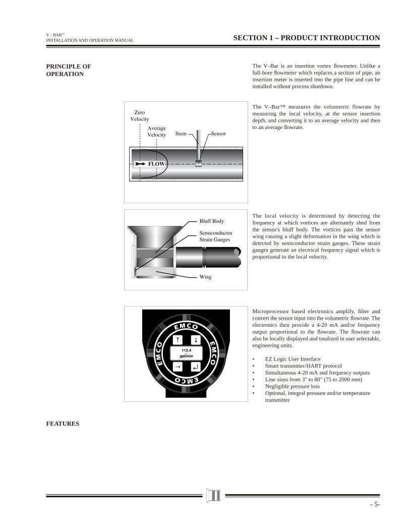
The V–Bar is an insertion vortex fl owmeter. Unlike a full-bore fl owmeter which replaces a section of pipe, an insertion meter is inserted into the pipe line and can be installed without process shutdown.
The V–Bar™ measures the volumetric flowrate by measuring the local velocity, at the sensor insertion depth, and converting it to an average velocity and then to an average fl owrate.
The local velocity is determined by detecting the frequency at which vortices are alternately shed from the sensor's bluff body. The vortices pass the sensor wing causing a slight deformation in the wing which is detected by semiconductor strain gauges. These strain gauges generate an electrical frequency signal which is proportional to the local velocity.
Microprocessor based electronics amplify, fi lter and convert the sensor input into the volumetric fl owrate. The electronics then provide a 4-20 mA and/or frequency output proportional to the fl owrate. The fl owrate can also be locally displayed and totalized in user selectable, engineering units.
• EZ Logic User Interface• Smart transmitter/HART protocol• Simultaneous 4-20 mA and frequency outputs• Line sizes from 3" to 80" (75 to 2000 mm)• Negligible pressure loss• Optional, integral pressure and/or temperature transmitter
- 6 -
V - BAR™ INSTALLATION AND OPERATION MANUAL
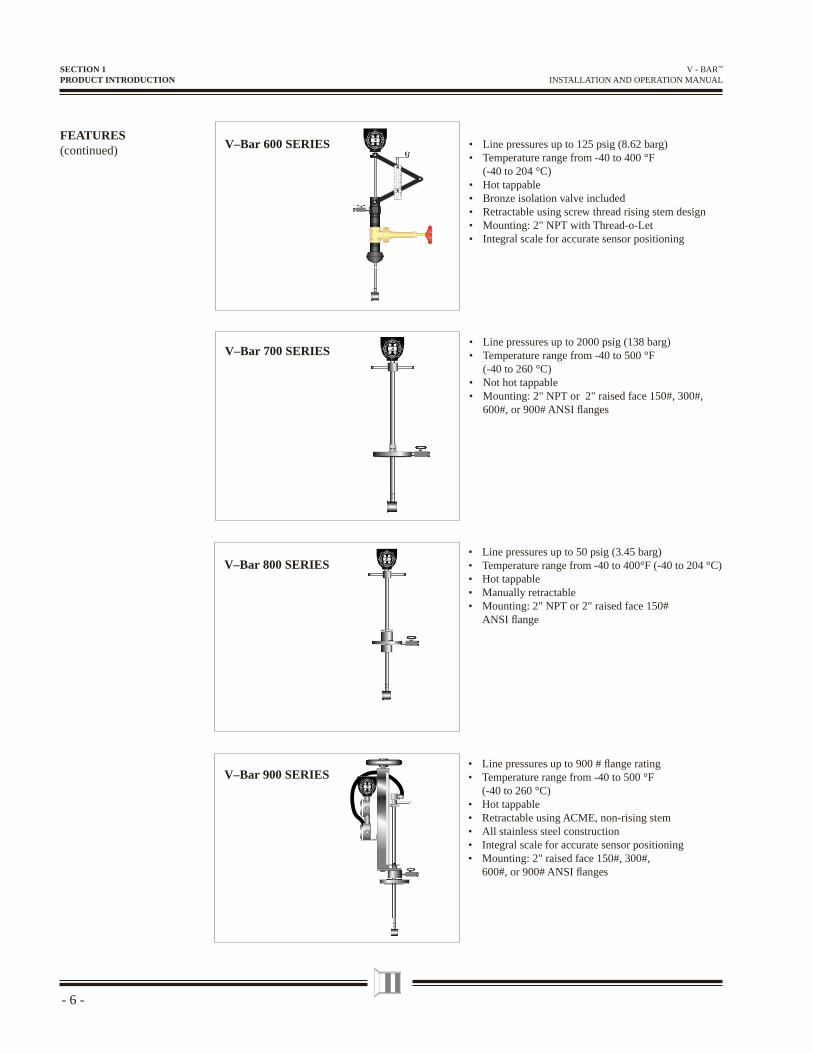
FEATURES(continued) V–Bar 600 SERIES
V–Bar 900 SERIES• Line pressures up to 900 # fl ange rating• Temperature range from -40 to 500 °F
(-40 to 260 °C)• Hot tappable• Retractable using ACME, non-rising stem• All stainless steel construction• Integral scale for accurate sensor positioning• Mounting: 2" raised face 150#, 300#, 600#, or 900# ANSI fl anges
V–Bar 700 SERIES• Line pressures up to 2000 psig (138 barg)• Temperature range from -40 to 500 °F
(-40 to 260 °C)• Not hot tappable• Mounting: 2" NPT or 2" raised face 150#, 300#, 600#, or 900# ANSI fl anges
V–Bar 800 SERIES• Line pressures up to 50 psig (3.45 barg)• Temperature range from -40 to 400°F (-40 to 204 °C)• Hot tappable• Manually retractable• Mounting: 2" NPT or 2" raised face 150# ANSI fl ange
SECTION 1PRODUCT INTRODUCTION
• Line pressures up to 125 psig (8.62 barg)• Temperature range from -40 to 400 °F
(-40 to 204 °C)• Hot tappable• Bronze isolation valve included• Retractable using screw thread rising stem design• Mounting: 2" NPT with Thread-o-Let• Integral scale for accurate sensor positioning
- 7-
V - BAR™ INSTALLATION AND OPERATION MANUAL SECTION 2 – INSPECTION
Upon receiving your EMCO equipment, verify that all materials on the packing list are present. In addition, check for possible shipping damage, and notify the freight carrier or your EMCO representative if any has occurred.
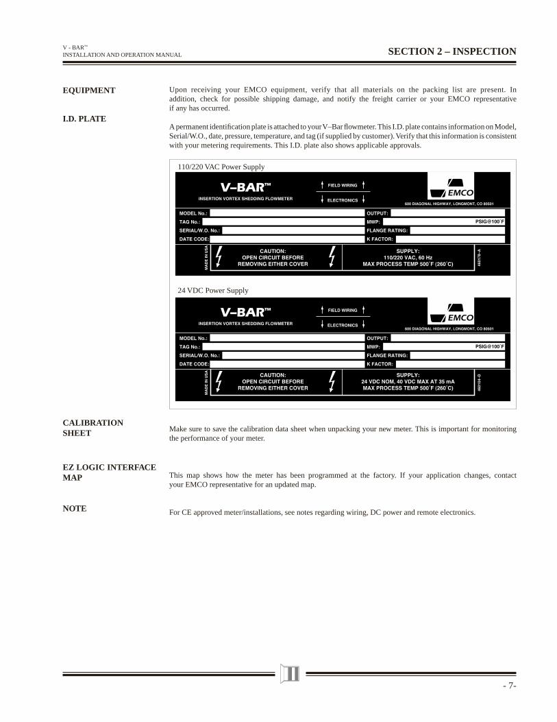
A permanent identifi cation plate is attached to your V–Bar fl owmeter. This I.D. plate contains information on Model, Serial/W.O., date, pressure, temperature, and tag (if supplied by customer). Verify that this information is consistent with your metering requirements. This I.D. plate also shows applicable approvals.
EQUIPMENT
I.D. PLATE
Make sure to save the calibration data sheet when unpacking your new meter. This is important for monitoring the performance of your meter.
This map shows how the meter has been programmed at the factory. If your application changes, contact your EMCO representative for an updated map.
For CE approved meter/installations, see notes regarding wiring, DC power and remote electronics.
24 VDC Power Supply
110/220 VAC Power Supply
EZ LOGIC INTERFACEMAP
NOTE
CALIBRATIONSHEET
- 8 -
V - BAR™ INSTALLATION AND OPERATION MANUALSECTION 3 – GUIDELINES
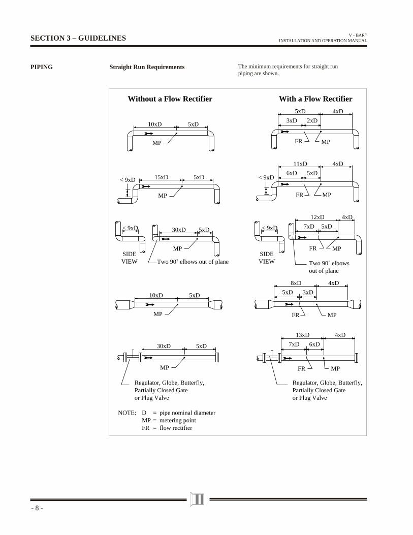
The minimum requirements for straight run piping are shown.
Straight Run RequirementsPIPING
3xD
4xD5xD
2xD
FR
FR
FR
FR
FR
6xD
4xD11xD
5xD
7xD
4xD12xD
5xD
5xD
4xD8xD
3xD
7xD
4xD13xD
6xD
Regulator, Globe, Butterfly,Partially Closed Gateor Plug Valve
MP MP
MP
MP
MP
MP
MP
MP
MP
MP
5xD10xD
Without a Flow Rectifier With a Flow Rectifier
5xD15xD< 9xD < 9xD
SIDEVIEW
SIDEVIEW
5xD< 9xD 30xD < 9xD
5xD10xD
5xD30xD
Regulator, Globe, Butterfly,Partially Closed Gateor Plug Valve
Two 90˚ elbowsout of plane
Two 90˚ elbows out of plane
NOTE: D = pipe nominal diameterMP = metering pointFR = flow rectifier
- 9-
V - BAR™ INSTALLATION AND OPERATION MANUAL
SECTION 3GUIDELINES
PIPING(continued)
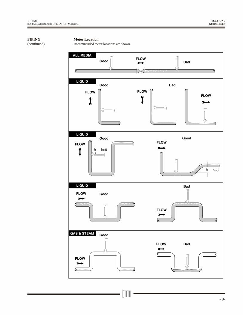
Meter LocationRecommended meter locations are shown.
- 10 -
V - BAR™ INSTALLATION AND OPERATION MANUAL
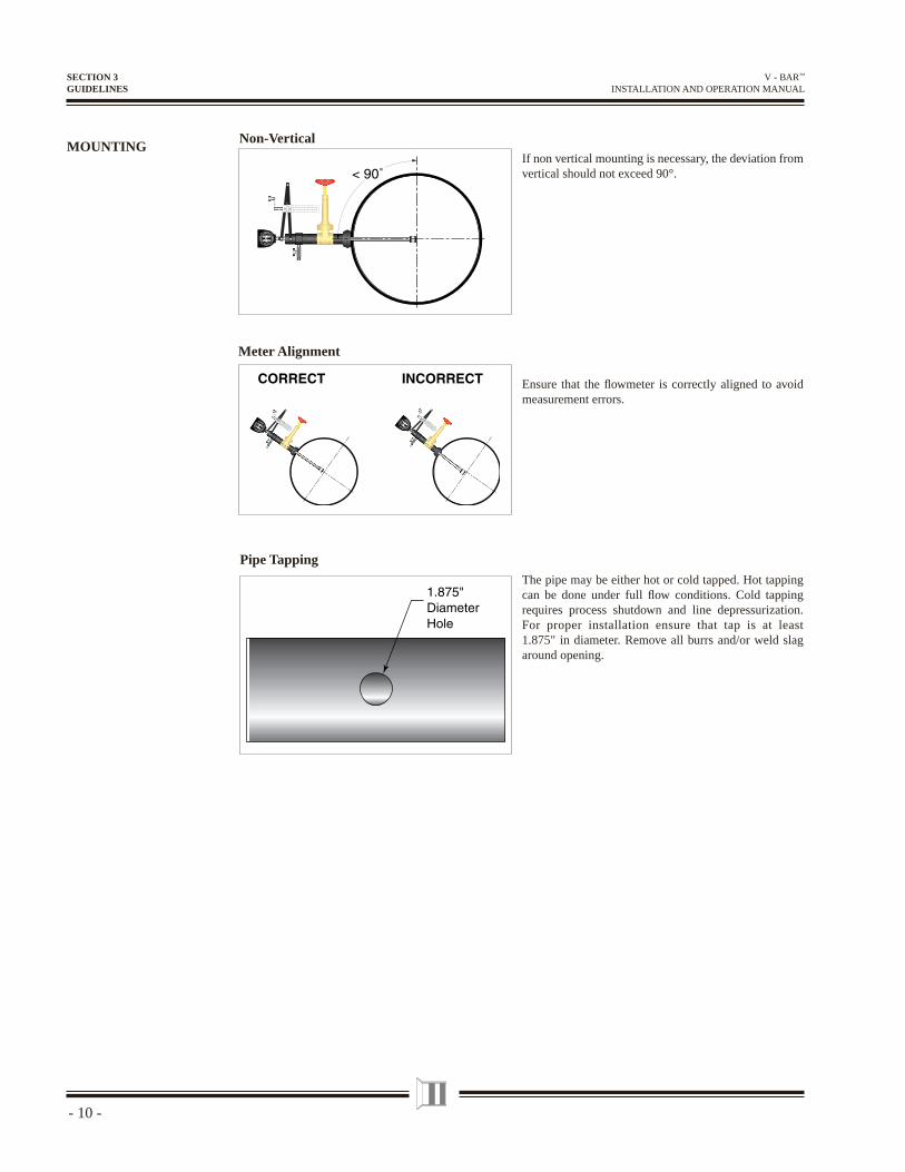
MOUNTINGNon-Vertical
112.
4ga
l/minE
MC
O
EMCO
EM
C
O
E MCO
112.
4ga
l/min
EM
C
O
EMC
O
EM
C
O
E MC
O
Meter Alignment
Pipe Tapping
SECTION 3GUIDELINES
If non vertical mounting is necessary, the deviation from vertical should not exceed 90°.
Ensure that the fl owmeter is correctly aligned to avoid measurement errors.
The pipe may be either hot or cold tapped. Hot tapping can be done under full fl ow conditions. Cold tapping requires process shutdown and line depressurization. For proper installation ensure that tap is at least 1.875" in diameter. Remove all burrs and/or weld slag around opening.
- 11-
V - BAR™ INSTALLATION AND OPERATION MANUAL
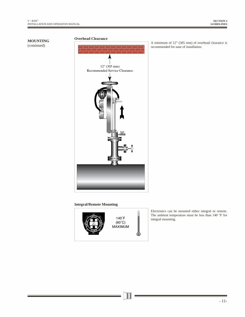
Overhead ClearanceMOUNTING(continued)
Integral/Remote Mounting
A minimum of 12" (305 mm) of overhead clearance is recommended for ease of installation.
SECTION 3GUIDELINES
Electronics can be mounted either integral or remote. The ambient temperature must be less than 140 °F for integral mounting.
- 12 -
V - BAR™ INSTALLATION AND OPERATION MANUAL
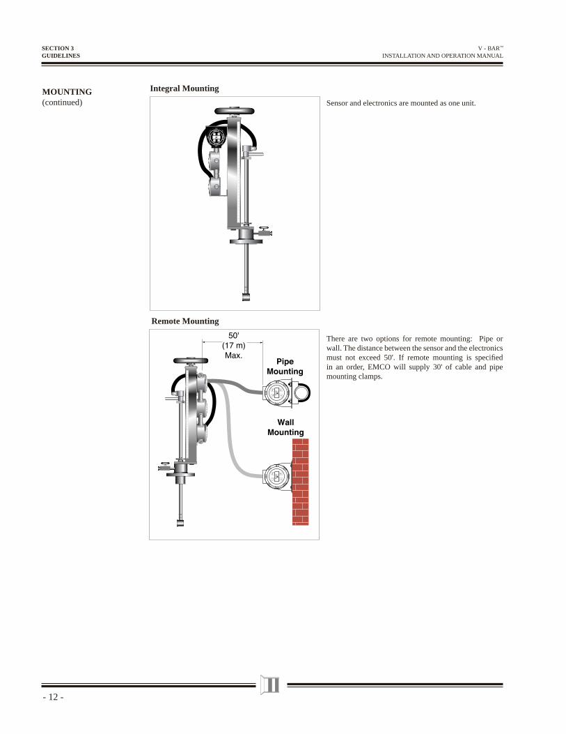
Integral Mounting
SECTION 3GUIDELINES
Sensor and electronics are mounted as one unit.
There are two options for remote mounting: Pipe or wall. The distance between the sensor and the electronics must not exceed 50'. If remote mounting is specifi ed in an order, EMCO will supply 30' of cable and pipe mounting clamps.
MOUNTING(continued)
Remote Mounting
112.4
gal/min
- 13-
V - BAR™ INSTALLATION AND OPERATION MANUAL
Pipe ConnectionsMOUNTING(continued)
SECTION 3GUIDELINES
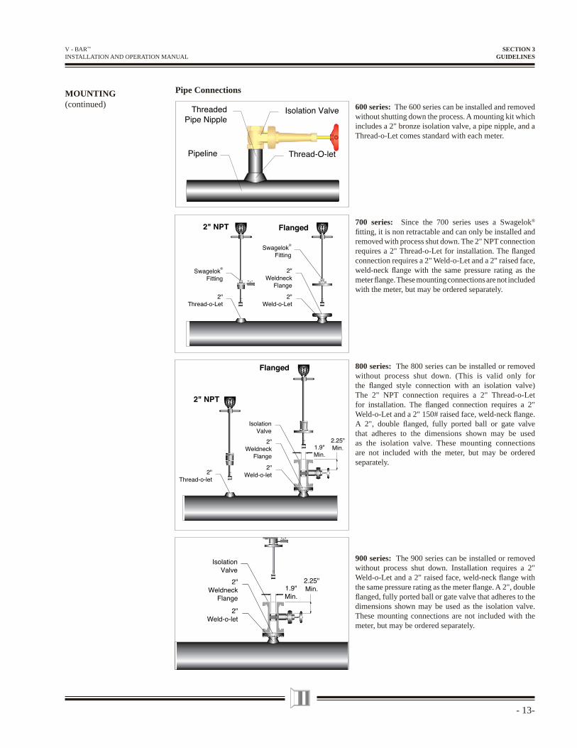
600 series: The 600 series can be installed and removed without shutting down the process. A mounting kit which includes a 2" bronze isolation valve, a pipe nipple, and a Thread-o-Let comes standard with each meter.
700 series: Since the 700 series uses a Swagelok®
fi tting, it is non retractable and can only be installed and removed with process shut down. The 2" NPT connection requires a 2" Thread-o-Let for installation. The fl anged connection requires a 2" Weld-o-Let and a 2" raised face, weld-neck fl ange with the same pressure rating as the meter fl ange. These mounting connections are not included with the meter, but may be ordered separately.
800 series: The 800 series can be installed or removed without process shut down. (This is valid only for the fl anged style connection with an isolation valve) The 2" NPT connection requires a 2" Thread-o-Let for installation. The fl anged connection requires a 2" Weld-o-Let and a 2" 150# raised face, weld-neck fl ange. A 2", double fl anged, fully ported ball or gate valve that adheres to the dimensions shown may be used as the isolation valve. These mounting connections are not included with the meter, but may be ordered separately.
900 series: The 900 series can be installed or removed without process shut down. Installation requires a 2" Weld-o-Let and a 2" raised face, weld-neck fl ange with the same pressure rating as the meter fl ange. A 2", double fl anged, fully ported ball or gate valve that adheres to the dimensions shown may be used as the isolation valve. These mounting connections are not included with the meter, but may be ordered separately.
- 14 -
V - BAR™ INSTALLATION AND OPERATION MANUAL
V–BAR 600SERIES
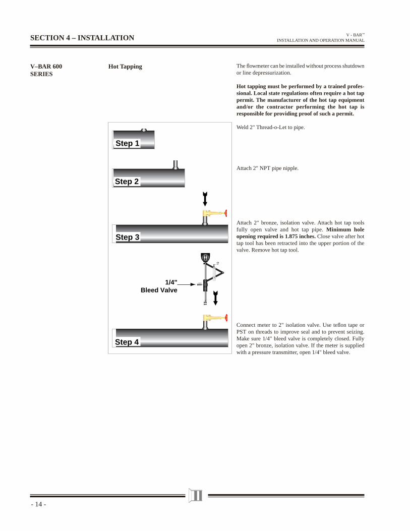
Hot Tapping The fl owmeter can be installed without process shutdown or line depressurization.
Hot tapping must be performed by a trained profes-sional. Local state regulations often require a hot tap permit. The manufacturer of the hot tap equipment and/or the contractor performing the hot tap is responsible for providing proof of such a permit.
Weld 2" Thread-o-Let to pipe.
Attach 2" NPT pipe nipple.
Attach 2" bronze, isolation valve. Attach hot tap tools fully open valve and hot tap pipe. Minimum hole opening required is 1.875 inches. Close valve after hot tap tool has been retracted into the upper portion of the valve. Remove hot tap tool.
Connect meter to 2" isolation valve. Use tefl on tape or PST on threads to improve seal and to prevent seizing. Make sure 1/4" bleed valve is completely closed. Fully open 2" bronze, isolation valve. If the meter is supplied with a pressure transmitter, open 1/4" bleed valve.
SECTION 4 – INSTALLATION
112.4
gal/min
E MCO
EM
CO
EMCO
EM
CO
Step 1
Step 4
Step 3
Step 2
1/4"Bleed Valve
- 15-
V - BAR™ INSTALLATION AND OPERATION MANUAL
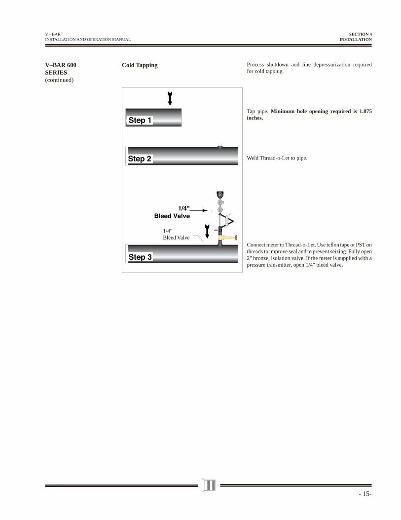
Process shutdown and line depressurization required for cold tapping.
Tap pipe. Minimum hole opening required is 1.875 inches.
Weld Thread-o-Let to pipe.
Connect meter to Thread-o-Let. Use tefl on tape or PST on threads to improve seal and to prevent seizing. Fully open 2" bronze, isolation valve. If the meter is supplied with a pressure transmitter, open 1/4" bleed valve.
V–BAR 600SERIES(continued)
Cold Tapping
SECTION 4INSTALLATION
1/4"Bleed Valve
- 16 -
V - BAR™ INSTALLATION AND OPERATION MANUAL
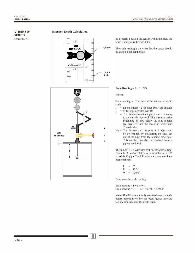
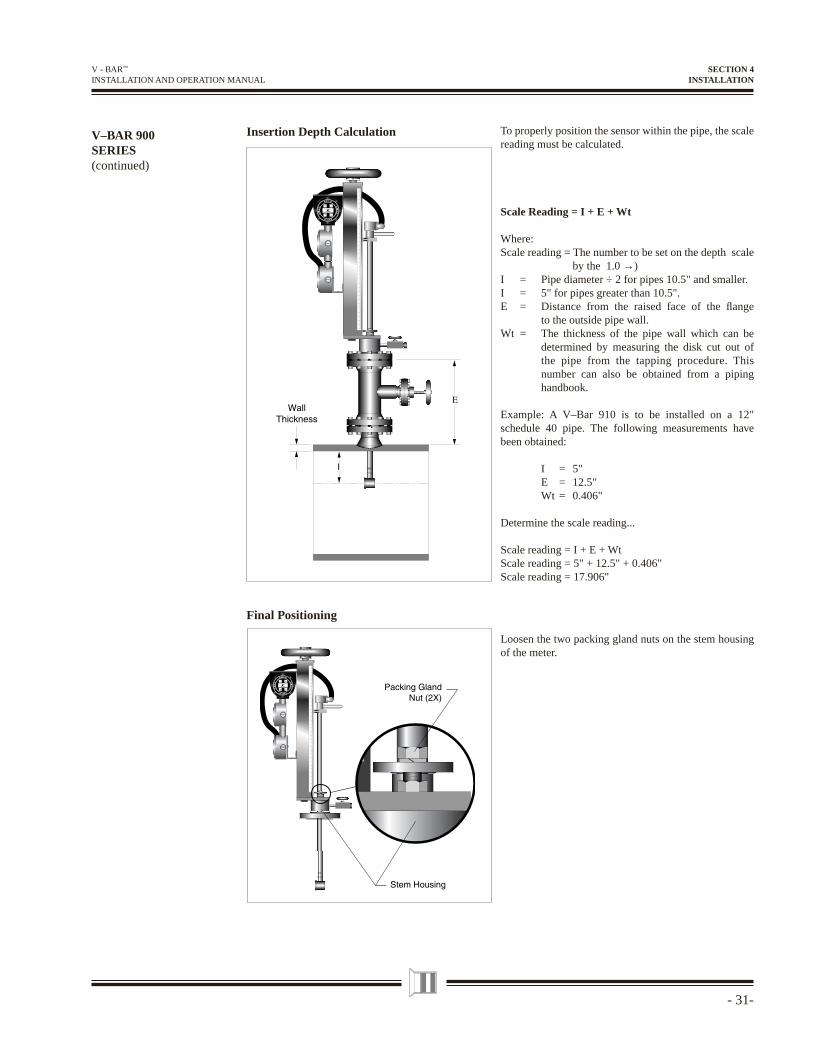
To properly position the sensor within the pipe, the scale reading must be calculated.
The scale reading is the value that the cursor should be set to on the depth scale.
Scale Reading = I + E + Wt
Where:
Scale reading = The value to be set on the depth scaleI = pipe diameter ÷ 2 for pipes 10.5" and smallerI = 5" for pipes greater than 10E = The distance from the top of the stem housing
to the outside pipe wall. This distance varies depending on how tightly the pipe nipples are screwed into the isolation valve and Thread-o-Let.
Wt = The thickness of the pipe wall which can be determined by measuring the disk cut out of the pipe from the tapping procedure. This number can also be obtained from a piping handbook.
The sum of I + E + Wt is used as the depth scale setting. Example: A V–Bar 600 is to be installed on a 12" schedule 40 pipe. The following measurements have been obtained:
I = 5" E = 12.5" Wt = 0.406"
Determine the scale reading...
Scale reading = I + E + WtScale reading = 5" + 12.5" + 0.406 = 17.906"
Note: The distance the fully retracted sensor travels before becoming visible has been fi gured into the factory adjustment of the depth scale.
Insertion Depth CalculationV–BAR 600SERIES(continued)
SECTION 4INSTALLATION
- 17-
V - BAR™ INSTALLATION AND OPERATION MANUAL
V–BAR 600SERIES(continued)
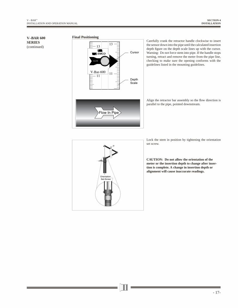
Final PositioningCarefully crank the retractor handle clockwise to insert the sensor down into the pipe until the calculated insertion depth fi gure on the depth scale lines up with the cursor. Warning: Do not force stem into pipe. If the handle stops turning, retract and remove the meter from the pipe line, checking to make sure the opening conforms with the guidelines listed in the mounting guidelines.
Align the retractor bar assembly so the fl ow direction is parallel to the pipe, pointed downstream.
Lock the stem in position by tightening the orientation set screw.
CAUTION: Do not allow the orientation of the meter or the insertion depth to change after inser-tion is complete. A change in insertion depth oralignment will cause inaccurate readings.
SECTION 4INSTALLATION
- 18 -
V - BAR™ INSTALLATION AND OPERATION MANUAL
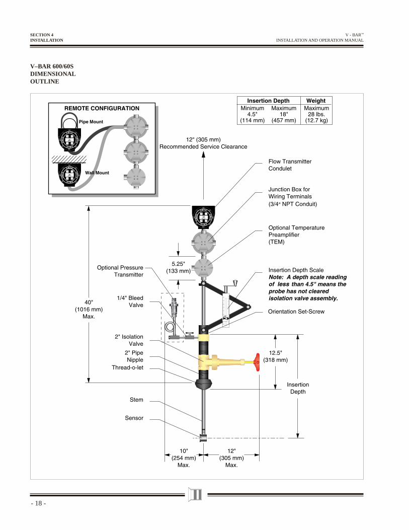
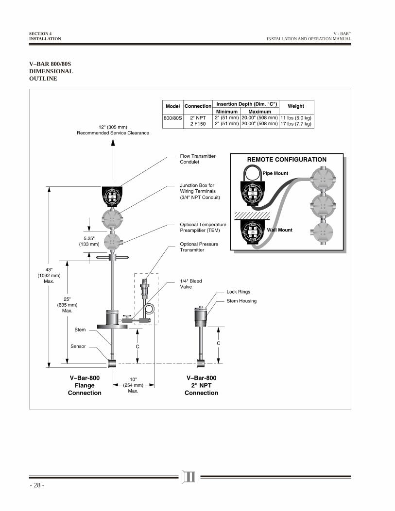
V–BAR 600/60SDIMENSIONALOUTLINE
SECTION 4INSTALLATION
- 19-
V - BAR™ INSTALLATION AND OPERATION MANUAL
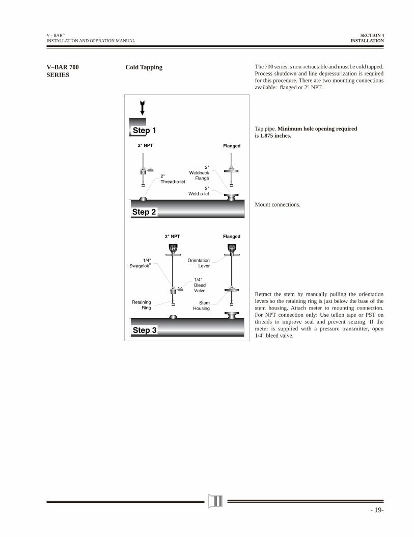
V–BAR 700SERIES
The 700 series is non-retractable and must be cold tapped. Process shutdown and line depressurization is required for this procedure. There are two mounting connections available: fl anged or 2" NPT.
Tap pipe. Minimum hole opening required is 1.875 inches.
Mount connections.
Retract the stem by manually pulling the orientation levers so the retaining ring is just below the base of the stem housing. Attach meter to mounting connection. For NPT connection only: Use tefl on tape or PST on threads to improve seal and prevent seizing. If the meter is supplied with a pressure transmitter, open 1/4" bleed valve.
Cold Tapping
SECTION 4INSTALLATION
- 20 -
V - BAR™ INSTALLATION AND OPERATION MANUAL
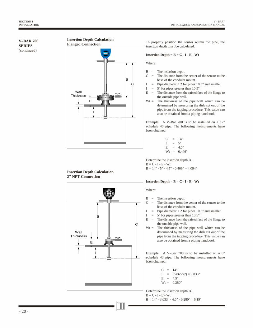
To properly position the sensor within the pipe, the insertion depth must be calculated.
Insertion Depth = B = C - I - E - Wt
Where:
B = The insertion depth.C = The distance from the center of the sensor to the
base of the condulet mount.I = Pipe diameter ÷ 2 for pipes 10.5" and smaller.I = 5" for pipes greater than 10.5".E = The distance from the raised face of the fl ange to
the outside pipe wall. Wt = The thickness of the pipe wall which can be
determined by measuring the disk cut out of the pipe from the tapping procedure. This value can also be obtained from a piping handbook.
Example: A V–Bar 700 is to be installed on a 12" schedule 40 pipe. The following measurements have been obtained:
C = 14" I = 5" E = 4.5" Wt = 0.406"
Determine the insertion depth B...B = C - I - E - WtB = 14" - 5" - 4.5" - 0.406" = 4.094"
Insertion Depth Calculation Flanged Connection
Insertion Depth Calculation 2" NPT Connection
Insertion Depth = B = C - I - E - Wt
Where:
B = The insertion depth.C = The distance from the center of the sensor to the
base of the condulet mount.I = Pipe diameter ÷ 2 for pipes 10.5" and smaller.I = 5" for pipes greater than 10.5".E = The distance from the raised face of the fl ange to
the outside pipe wall. Wt = The thickness of the pipe wall which can be
determined by measuring the disk cut out of the pipe from the tapping procedure. This value can also be obtained from a piping handbook.
Example: A V–Bar 700 is to be installed on a 6" schedule 40 pipe. The following measurements have been obtained:
C = 14" I = (6.065"/2) = 3.033" E = 4.5" Wt = 0.280"
Determine the insertion depth B...B = C - I - E - WtB = 14" - 3.033" - 4.5" - 0.280" = 6.19"
V–BAR 700SERIES(continued)
SECTION 4INSTALLATION
- 21-
V - BAR™ INSTALLATION AND OPERATION MANUAL
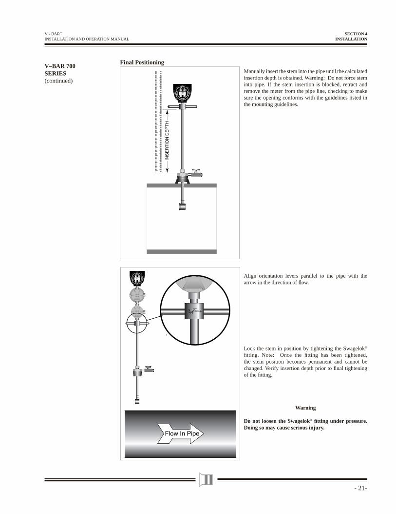
V–BAR 700SERIES(continued)
Final PositioningManually insert the stem into the pipe until the calculated insertion depth is obtained. Warning: Do not force stem into pipe. If the stem insertion is blocked, retract and remove the meter from the pipe line, checking to make sure the opening conforms with the guidelines listed in the mounting guidelines.
Align orientation levers parallel to the pipe with the arrow in the direction of fl ow.
Lock the stem in position by tightening the Swagelok® fi tting. Note: Once the fi tting has been tightened, the stem position becomes permanent and cannot be changed. Verify insertion depth prior to fi nal tightening of the fi tting.
Warning
Do not loosen the Swagelok® fi tting under pressure. Doing so may cause serious injury.
SECTION 4INSTALLATION
- 22 -
V - BAR™ INSTALLATION AND OPERATION MANUAL
V–BAR 700DIMENSIONALOUTLINE
SECTION 4INSTALLATION
- 23-
V - BAR™ INSTALLATION AND OPERATION MANUAL
V–BAR 800SERIES
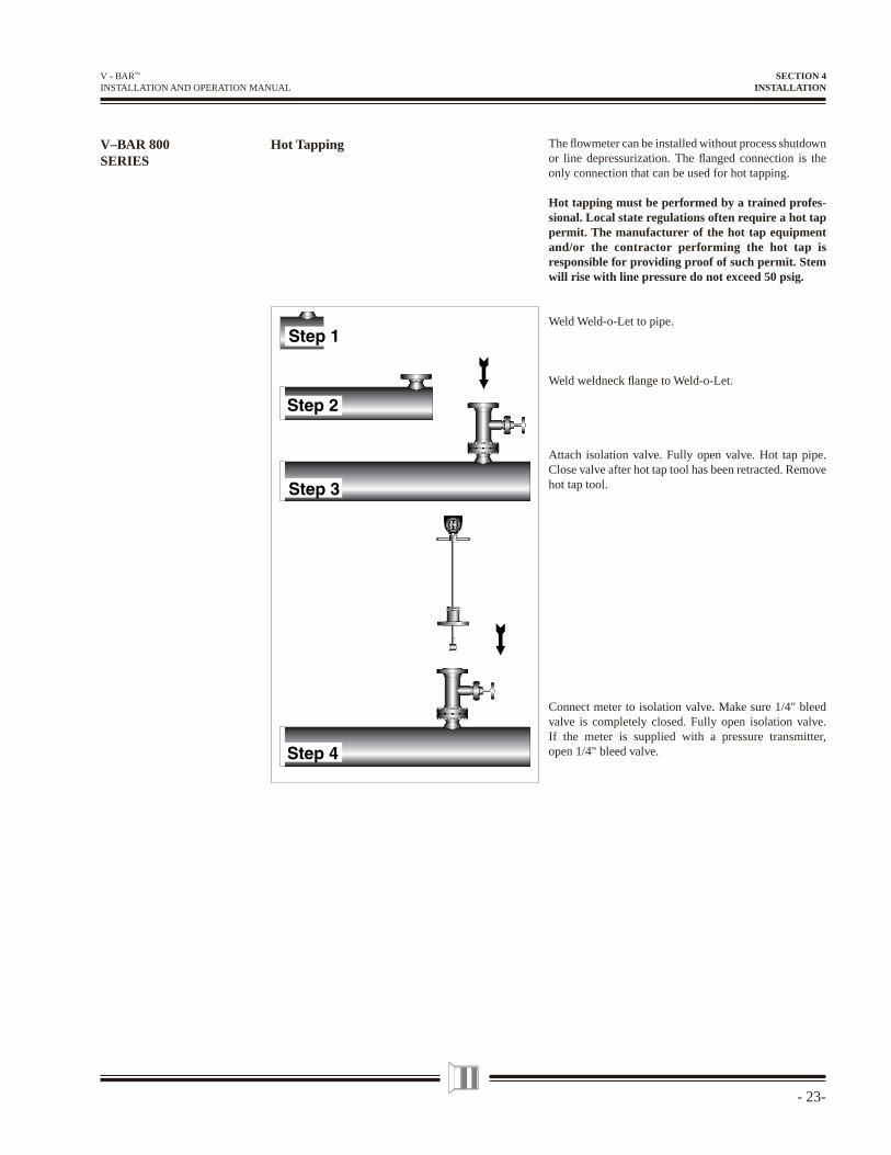
Hot Tapping The fl owmeter can be installed without process shutdown or line depressurization. The fl anged connection is the only connection that can be used for hot tapping.
Hot tapping must be performed by a trained profes-sional. Local state regulations often require a hot tap permit. The manufacturer of the hot tap equipment and/or the contractor performing the hot tap is responsible for providing proof of such permit. Stem will rise with line pressure do not exceed 50 psig.
Weld Weld-o-Let to pipe.
Weld weldneck fl ange to Weld-o-Let.
Attach isolation valve. Fully open valve. Hot tap pipe. Close valve after hot tap tool has been retracted. Remove hot tap tool.
Connect meter to isolation valve. Make sure 1/4" bleed valve is completely closed. Fully open isolation valve. If the meter is supplied with a pressure transmitter, open 1/4" bleed valve.
SECTION 4INSTALLATION
- 24 -
V - BAR™ INSTALLATION AND OPERATION MANUAL
V–BAR 800SERIES(continued)
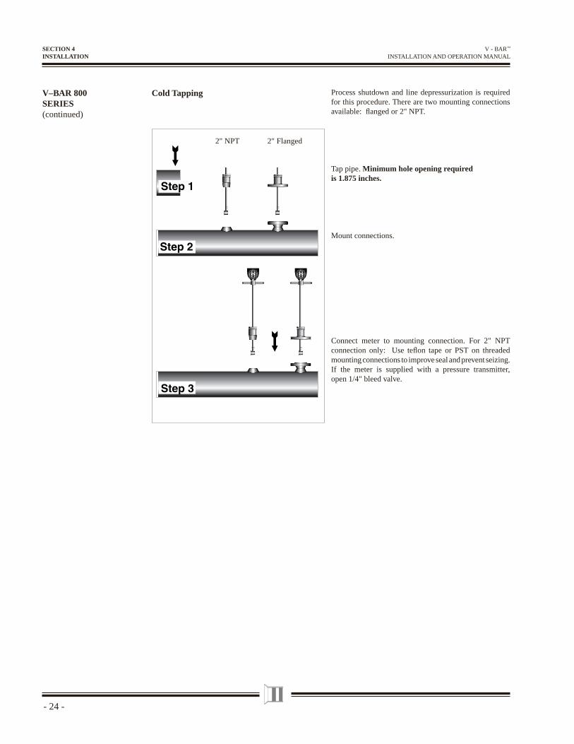
Process shutdown and line depressurization is required for this procedure. There are two mounting connections available: fl anged or 2" NPT.
Tap pipe. Minimum hole opening required is 1.875 inches.
Mount connections.
Connect meter to mounting connection. For 2" NPT connection only: Use tefl on tape or PST on threaded mounting connections to improve seal and prevent seizing. If the meter is supplied with a pressure transmitter, open 1/4" bleed valve.
Cold Tapping
SECTION 4INSTALLATION
2" NPT 2" Flanged
- 25-
V - BAR™ INSTALLATION AND OPERATION MANUAL
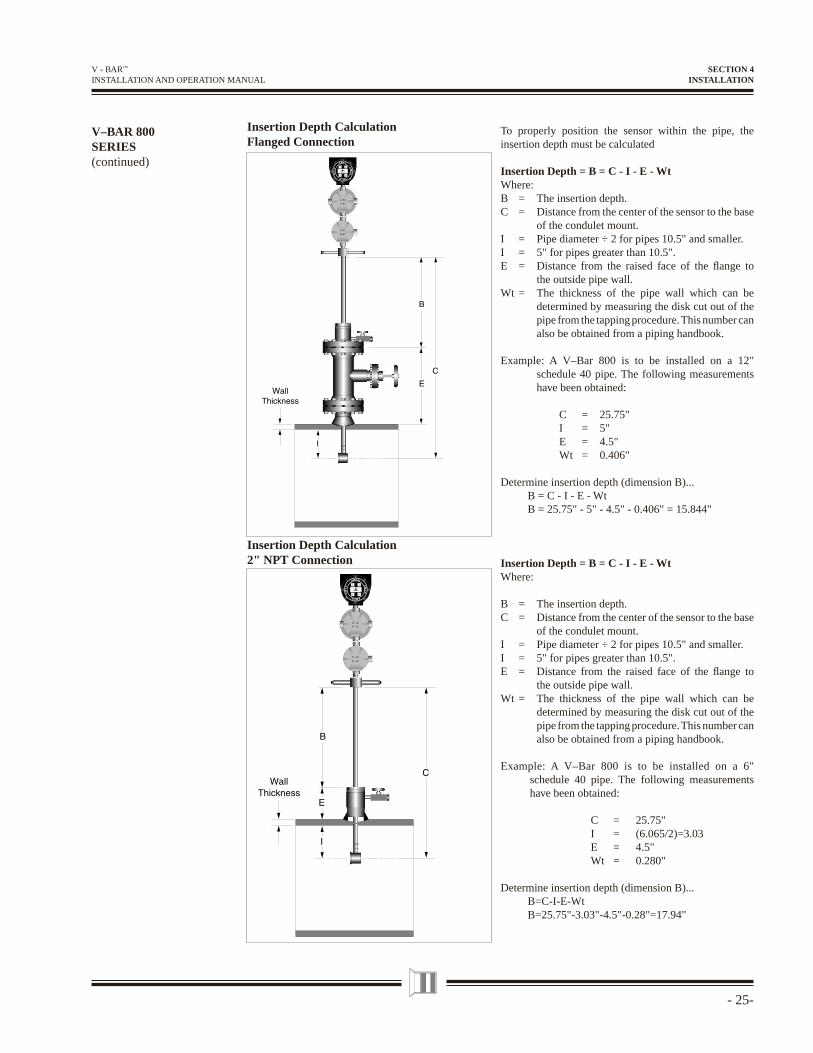
Insertion Depth Calculation Flanged Connection
V–BAR 800SERIES(continued)
To properly position the sensor within the pipe, the insertion depth must be calculated
Insertion Depth = B = C - I - E - WtWhere:B = The insertion depth.C = Distance from the center of the sensor to the base
of the condulet mount.I = Pipe diameter ÷ 2 for pipes 10.5" and smaller.I = 5" for pipes greater than 10.5".E = Distance from the raised face of the fl ange to
the outside pipe wall.Wt = The thickness of the pipe wall which can be
determined by measuring the disk cut out of the pipe from the tapping procedure. This number can also be obtained from a piping handbook.
Example: A V–Bar 800 is to be installed on a 12" schedule 40 pipe. The following measurements have been obtained:
C = 25.75" I = 5" E = 4.5" Wt = 0.406"
Determine insertion depth (dimension B)... B = C - I - E - Wt B = 25.75" - 5" - 4.5" - 0.406" = 15.844"
Insertion Depth = B = C - I - E - WtWhere:
B = The insertion depth.C = Distance from the center of the sensor to the base
of the condulet mount.I = Pipe diameter ÷ 2 for pipes 10.5" and smaller.I = 5" for pipes greater than 10.5".E = Distance from the raised face of the fl ange to
the outside pipe wall.Wt = The thickness of the pipe wall which can be
determined by measuring the disk cut out of the pipe from the tapping procedure. This number can also be obtained from a piping handbook.
Example: A V–Bar 800 is to be installed on a 6" schedule 40 pipe. The following measurements have been obtained:
C = 25.75" I = (6.065/2)=3.03 E = 4.5" Wt = 0.280"
Determine insertion depth (dimension B)... B=C-I-E-Wt B=25.75"-3.03"-4.5"-0.28"=17.94"
Insertion Depth Calculation 2" NPT Connection
SECTION 4INSTALLATION
- 26 -
V - BAR™ INSTALLATION AND OPERATION MANUAL
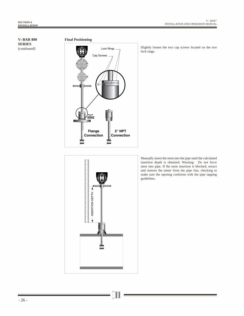
Final PositioningV–BAR 800SERIES(continued) Slightly loosen the two cap screws located on the two
lock rings.
Manually insert the stem into the pipe until the calculated insertion depth is obtained. Warning: Do not force stem into pipe. If the stem insertion is blocked, retract and remove the meter from the pipe line, checking to make sure the opening conforms with the pipe tapping guidelines.
SECTION 4INSTALLATION
- 27-
V - BAR™ INSTALLATION AND OPERATION MANUAL
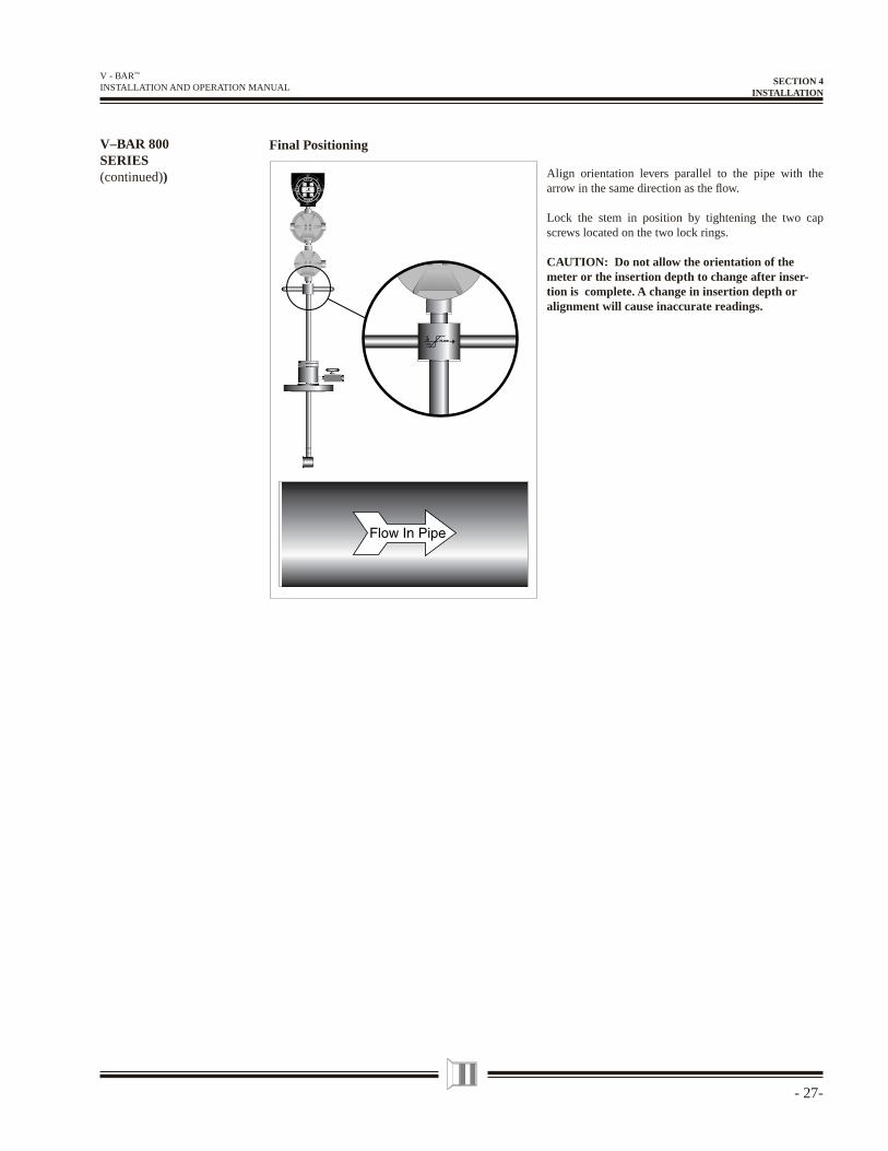
Align orientation levers parallel to the pipe with the arrow in the same direction as the fl ow.
Lock the stem in position by tightening the two cap screws located on the two lock rings.
CAUTION: Do not allow the orientation of the meter or the insertion depth to change after inser-tion is complete. A change in insertion depth oralignment will cause inaccurate readings.
V–BAR 800SERIES(continued))
Final Positioning
SECTION 4INSTALLATION
- 28 -
V - BAR™ INSTALLATION AND OPERATION MANUAL
V–BAR 800/80SDIMENSIONALOUTLINE
SECTION 4INSTALLATION
- 29-
V - BAR™ INSTALLATION AND OPERATION MANUAL
V–BAR 900SERIES
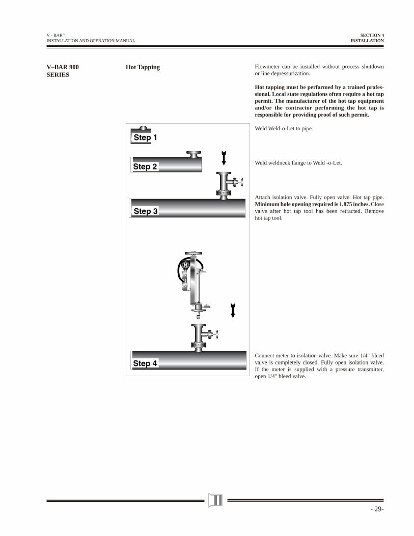
Hot Tapping Flowmeter can be installed without process shutdown or line depressurization.
Hot tapping must be performed by a trained profes-sional. Local state regulations often require a hot tap permit. The manufacturer of the hot tap equipment and/or the contractor performing the hot tap is responsible for providing proof of such permit.
Weld Weld-o-Let to pipe.
Weld weldneck fl ange to Weld -o-Let.
Attach isolation valve. Fully open valve. Hot tap pipe. Minimum hole opening required is 1.875 inches. Close valve after hot tap tool has been retracted. Remove hot tap tool.
Connect meter to isolation valve. Make sure 1/4" bleed valve is completely closed. Fully open isolation valve. If the meter is supplied with a pressure transmitter, open 1/4" bleed valve.
SECTION 4INSTALLATION
- 30 -
V - BAR™ INSTALLATION AND OPERATION MANUAL
V–BAR 900SERIES(continued)
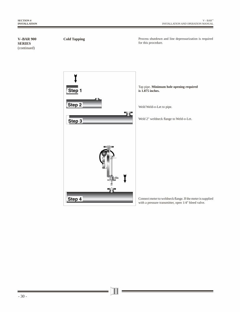
Cold Tapping Process shutdown and line depressurization is required for this procedure.
Tap pipe. Minimum hole opening required is 1.875 inches.
Weld Weld-o-Let to pipe.
Weld 2" weldneck fl ange to Weld-o-Let.
Connect meter to weldneck fl ange. If the meter is supplied with a pressure transmitter, open 1/4" bleed valve.
SECTION 4INSTALLATION
- 31-
V - BAR™ INSTALLATION AND OPERATION MANUAL
To properly position the sensor within the pipe, the scale reading must be calculated.
Scale Reading = I + E + Wt
Where:Scale reading = The number to be set on the depth scale
by the 1.0 →)I = Pipe diameter ÷ 2 for pipes 10.5" and smaller.I = 5" for pipes greater than 10.5".E = Distance from the raised face of the fl ange
to the outside pipe wall. Wt = The thickness of the pipe wall which can be
determined by measuring the disk cut out of the pipe from the tapping procedure. This number can also be obtained from a piping handbook.
Example: A V–Bar 910 is to be installed on a 12" schedule 40 pipe. The following measurements have been obtained:
I = 5" E = 12.5" Wt = 0.406"
Determine the scale reading... Scale reading = I + E + WtScale reading = 5" + 12.5" + 0.406"Scale reading = 17.906"
V–BAR 900SERIES(continued)
Insertion Depth Calculation
Final Positioning
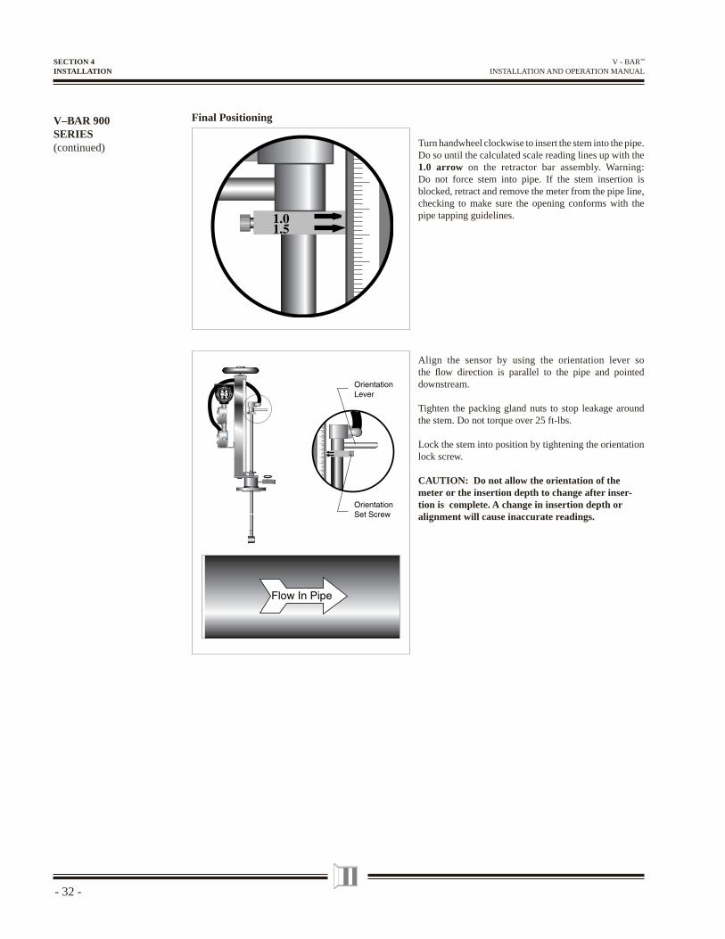
Loosen the two packing gland nuts on the stem housing of the meter.
SECTION 4INSTALLATION
- 32 -
V - BAR™ INSTALLATION AND OPERATION MANUAL
V–BAR 900SERIES(continued)
Final Positioning
Turn handwheel clockwise to insert the stem into the pipe. Do so until the calculated scale reading lines up with the 1.0 arrow on the retractor bar assembly. Warning: Do not force stem into pipe. If the stem insertion is blocked, retract and remove the meter from the pipe line, checking to make sure the opening conforms with the pipe tapping guidelines.
Align the sensor by using the orientation lever so the fl ow direction is parallel to the pipe and pointed downstream.
Tighten the packing gland nuts to stop leakage around the stem. Do not torque over 25 ft-lbs.
Lock the stem into position by tightening the orientation lock screw.
CAUTION: Do not allow the orientation of the meter or the insertion depth to change after inser-tion is complete. A change in insertion depth oralignment will cause inaccurate readings.
SECTION 4INSTALLATION
- 33-
V - BAR™ INSTALLATION AND OPERATION MANUAL
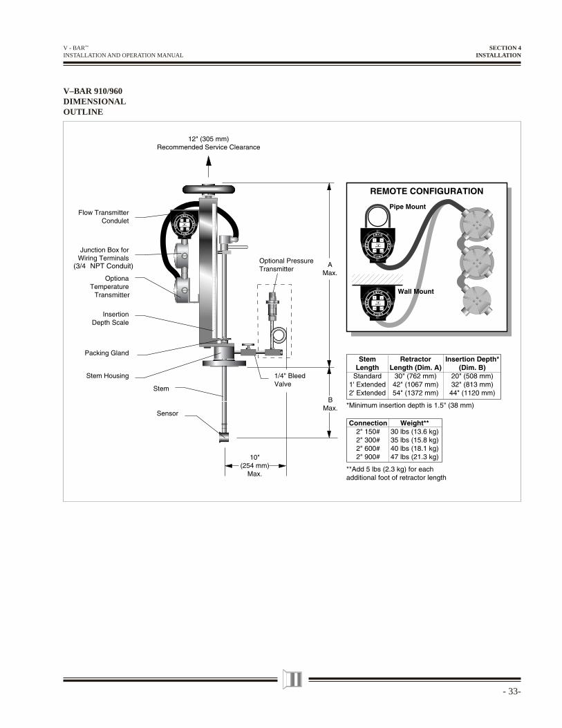
V–BAR 910/960DIMENSIONALOUTLINE
SECTION 4INSTALLATION
mitter
- 34 -
V - BAR™ INSTALLATION AND OPERATION MANUAL
To avoid personal injury or property damage from electrical shock or contact with live electrical systems, or from combustible material or explosive gases which can be ignited by electrical arcing, wiring and conduit must be installed in accordance with national, local laws, standards, codes, and industry practices.
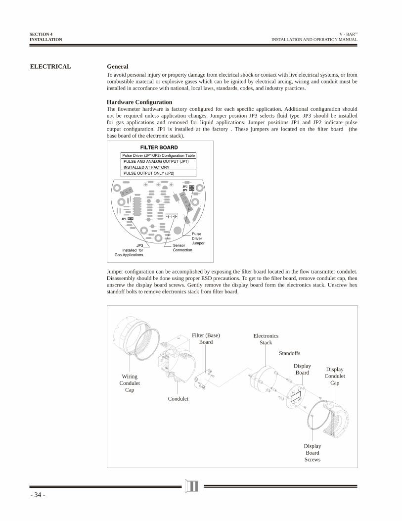
Hardware Confi gurationThe fl owmeter hardware is factory confi gured for each specifi c application. Additional confi guration should not be required unless application changes. Jumper position JP3 selects fl uid type. JP3 should be installed for gas applications and removed for liquid applications. Jumper positions JP1 and JP2 indicate pulse output confi guration. JP1 is installed at the factory . These jumpers are located on the fi lter board (the base board of the electronic stack).
ELECTRICAL General
DisplayCondulet
Cap
DisplayBoard
ElectronicsStack
Standoffs
Condulet
WiringCondulet
Cap
DisplayBoardScrews
Filter (Base)Board
Jumper confi guration can be accomplished by exposing the fi lter board located in the fl ow transmitter condulet. Disassembly should be done using proper ESD precautions. To get to the fi lter board, remove condulet cap, then unscrew the display board screws. Gently remove the display board form the electronics stack. Unscrew hex standoff bolts to remove electronics stack from fi lter board.
SECTION 4INSTALLATION
- 35-
V - BAR™ INSTALLATION AND OPERATION MANUAL
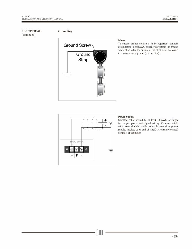
MeterTo ensure proper electrical noise rejection, connect ground strap (size 8 AWG or larger wire) from the ground screw attached to the outside of the electronics enclosure to a known earth ground (not the pipe).
Power SupplyShielded cable should be at least 18 AWG or larger for proper power and signal wiring. Connect shield wire from shielded cable to earth ground at power supply. Insulate other end of shield wire from electrical condulet at the meter.
SECTION 4INSTALLATION
ELECTRICAL(continued)
Grounding
- 36 -
V - BAR™ INSTALLATION AND OPERATION MANUAL
D.C. Power and Signal WiringELECTRICAL(continued)
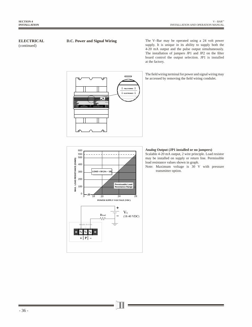
The V–Bar may be operated using a 24 volt power supply. It is unique in its ability to supply both the 4-20 mA output and the pulse output simultaneously. The installation of jumpers JP1 and JP2 on the fi lter board control the output selection. JP1 is installed at the factory.
The fi eld wiring terminal for power and signal wiring may be accessed by removing the fi eld wiring condulet.
Analog Output (JP1 installed or no jumpers)Scalable 4-20 mA output, 2 wire principle. Load resistor may be installed on supply or return line. Permissible load resistance values shown in graph. Note: Maximum voltage is 30 V with pressure
transmitter option.
Permissable LoadResistance Range
1800
100
MA
X.
LO
AD
RE
SIS
TA
NC
E (
OH
MS
)
POWER SUPPLY VOLTAGE (VDC)
200
300
400
550
LOAD = 50 (Vs – 18)
20 2924
500
600
SECTION 4INSTALLATION
- 37-
V - BAR™ INSTALLATION AND OPERATION MANUAL
ELECTRICAL(continued)
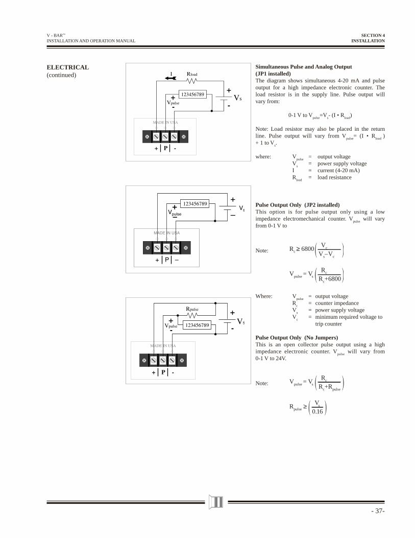
Simultaneous Pulse and Analog Output(JP1 installed)The diagram shows simultaneous 4-20 mA and pulse output for a high impedance electronic counter. The load resistor is in the supply line. Pulse output will vary from:
0-1 V to Vpulse
=Vs- (I • R
load)
Note: Load resistor may also be placed in the return line. Pulse output will vary from V
pulse= (I • R
load )
+ 1 to Vs.
where: Vpulse
= output voltage V
s = power supply voltage
I = current (4-20 mA) R
load = load resistance
Pulse Output Only (JP2 installed)This option is for pulse output only using a low impedance electromechanical counter. V
pulse will vary
from 0-1 V to
Note: Rc ≥Vc6800
Vs–Vc
Vpulse =RcVs Rc+6800
Where: Vpulse
= output voltage R
c = counter impedance
Vs = power supply voltage
Vc = minimum required voltage to
trip counter
Pulse Output Only (No Jumpers)This is an open collector pulse output using a high impedance electronic counter. V
pulse will vary from
0-1 V to 24V.
Note: Vpulse =RcVs Rc+Rpulse
Rpulse ≥Vs
0.16
SECTION 4INSTALLATION
- 38 -
V - BAR™ INSTALLATION AND OPERATION MANUAL
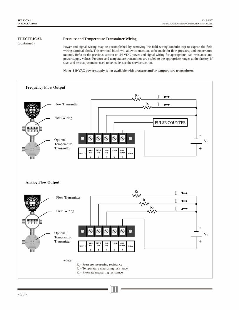
Pressure and Temperature Transmitter WiringELECTRICAL(continued)
Power and signal wiring may be accomplished by removing the fi eld wiring condulet cap to expose the fi eld wiring terminal block. This terminal block will allow connections to be made for fl ow, pressure, and temperature outputs. Refer to the previous section on 24 VDC power and signal wiring for appropriate load resistance and power supply values. Pressure and temperature transmitters are scaled to the appropriate ranges at the factory. If span and zero adjustments need to be made, see the service section.
Note: 110 VAC power supply is not available with pressure and/or temperature transmitters.
SECTION 4INSTALLATION
where: R
p= Pressure measuring resistance
RT= Temperature measuring resistance
RF= Flowrate measuring resistance
- 39-
V - BAR™ INSTALLATION AND OPERATION MANUAL
110 VAC Power and Signal WiringELECTRICAL(continued)
The V–Bar may be operated using 110 VAC power supply. The power supply converts the 110 VAC to 24 VDC. It is unique in its ability to supply both the 4-20 mA output and the pulse output simultaneously. The installation of jumpers JP1 and JP2 on the bottom of the 110 V power supply control the output selection. JP1 is installed at the factory.
Analog Output (JP1 installed or no jumpers)Scalable 4-20 mA output, 2 wire principle. Load resistor may be installed on supply or return line. R
load must be 250 .
Simultaneous Pulse and Analog Output(JP1 installed)Simultaneous 4-20 mA and pulse output for a high impedance electronic counter. Load resistor in the supply line. Pulse output will vary from:
0-1 V to Vpulse=
24 - (I • Rload)
where: Vpulse =
pulse output amplitude I = current (4-20 mA) Rl
oad = load resistance (250 )
Pulse Output Only (JP2 installed and analog jumper installed)This option is for pulse output only. V
pulse will vary
from:
Note:
Where: Vpulse
= pulse output amplitude R
C = counter impedance
VC
= minimum required voltage to trip counter
SECTION 4INSTALLATION
Rload
L
N110/220 Vac
Rload
L
N110/220 Vac Vpulse
L
N110/220 Vac
123456789+
—
Vpulse123456789
+
—
0 1V to V 24R
R 6800
Note : R 6800V
24 – V
pulseC
C
CC
C
− =+
≥
- 40 -
V - BAR™ INSTALLATION AND OPERATION MANUAL
Output wiring from the remote electronics is identical to the integral output wiring. However, the wiring from the remote electronics condulet to the electrical junction box must be performed in the fi eld. Connect the remote cable to the terminal block in the junction box as shown. If nonconductive conduit is used attach a ground strap from the ground screw on the remote electronics condulet to the ground screw on the sensor condulet. If the remote cable is cut to a shorter length, insulate shield with tape at electrical junction box.
Note: If remote mounting is required with a pressure and/or temperature transmitter, two power supplies are required for operation. One for the remote fl ow transmitter and one for the pressure and/or temperature transmitter.
Remote Wiring
Remote Electronics
Electrical Junction Box
ELECTRICAL(continued)
SECTION 4INSTALLATION
- 41-
V - BAR™ INSTALLATION AND OPERATION MANUAL
EZ LOGIC USERINTERFACE
General
The EZ Logic User Interface is a menu driven interface that consists of the top display menu and nine programming submenus. The submenus are called: Basic, Output, Fluid, Sensor, Reset, Service, Password, HART, and Display. These submenus are grouped by functionality. The fi rst is the Confi gure group, the second is Diagnose, and the third is Personalize. The Confi gure group is comprised of the Basic, Output, Fluid, and Sensor submenus. These submenus confi gure the fl owmeter for operation in a specifi c application. The Diagnose group is comprised of the Reset and Service submenus, which contain information relating to fl owmeter maintenance. Finally, the Personalize group is comprised of the HART and Display submenus. This group allows the user to customize the fl owmeter by choosing display parameters or changing the password. Each group has it's own icon; Confi gure "C", Diagnose "D", and Personalize "P". The user can identify the location within the interface map from the displayed icon in the upper or lower, right hand corner.
SECTION 5–EZ LOGIC PROGRAMMING
- 42 -
V - BAR™ INSTALLATION AND OPERATION MANUAL
INTERFACE MAP
SECTION 5EZ LOGIC PROGRAMMING
- 43-
V - BAR™ INSTALLATION AND OPERATION MANUAL
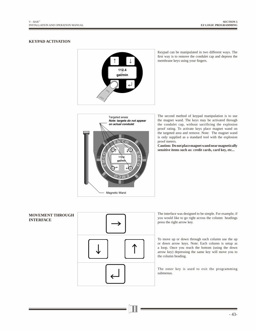
KEYPAD ACTIVATION
Keypad can be manipulated in two different ways. The fi rst way is to remove the condulet cap and depress the membrane keys using your fi ngers.
The second method of keypad manipulation is to use the magnet wand. The keys may be activated through the condulet cap, without sacrificing the explosion proof rating. To activate keys place magnet wand on the targeted area and remove. Note: The magnet wand is only supplied as a standard tool with the explosion proof meters.Caution: Do not place magnet wand near magnetically sensitive items such as: credit cards, card key, etc...
The interface was designed to be simple. For example; if you would like to go right across the column headings press the right arrow key.
To move up or down through each column use the up or down arrow keys. Note: Each column is setup as a loop. Once you reach the bottom (using the down arrow key) depressing the same key will move you to the column heading.
The enter key is used to exit the programming submenus.
MOVEMENT THROUGH INTERFACE
SECTION 5EZ LOGIC PROGRAMMING
EMCO
EM
CO
EMCO
EM
CO
- 44 -
V - BAR™ INSTALLATION AND OPERATION MANUAL
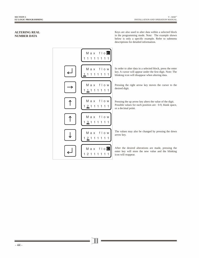
ALTERING REAL NUMBER DATA
Keys are also used to alter data within a selected block in the programming mode. Note: The example shown below is only a specifi c example. Refer to submenu descriptions for detailed information.
In order to alter data in a selected block, press the enter key. A cursor will appear under the fi rst digit. Note: The blinking icon will disappear when altering data.
Pressing the right arrow key moves the cursor to the desired digit.
Pressing the up arrow key alters the value of the digit.Possible values for each position are: 0-9, blank space, or a decimal point.
The values may also be changed by pressing the down arrow key.
After the desired alterations are made, pressing the enter key will store the new value and the blinking icon will reappear.
SECTION 5EZ LOGIC PROGRAMMING
- 45-
V - BAR™ INSTALLATION AND OPERATION MANUAL
ALTERING PRESET DATA
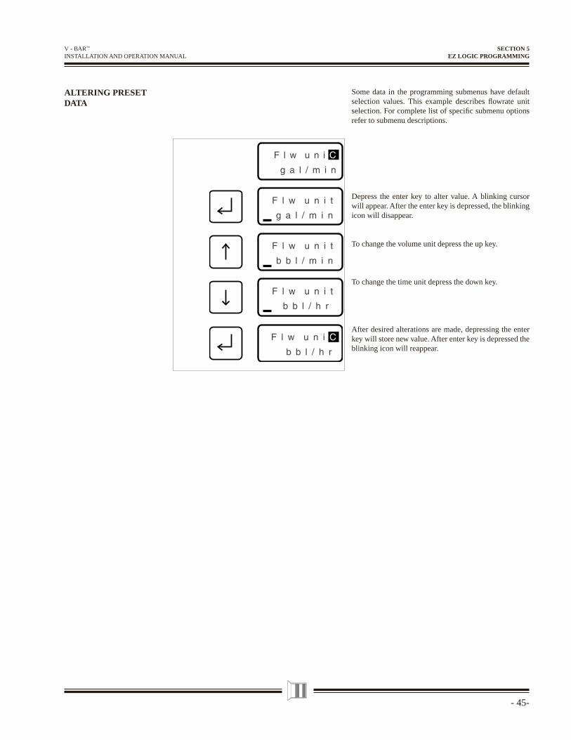
Some data in the programming submenus have default selection values. This example describes fl owrate unit selection. For complete list of specifi c submenu options refer to submenu descriptions.
Depress the enter key to alter value. A blinking cursor will appear. After the enter key is depressed, the blinking icon will disappear.
To change the volume unit depress the up key.
To change the time unit depress the down key.
After desired alterations are made, depressing the enter key will store new value. After enter key is depressed the blinking icon will reappear.
SECTION 5EZ LOGIC PROGRAMMING
- 46 -
V - BAR™ INSTALLATION AND OPERATION MANUAL
DisplayMenu
2 SEC
CorrectPassword
30.421gal/min
103.42×1 gal
10%
Errorcode 4
Password1000
FullAccess
Basicmenu
Password0234
ReadOnly
Basicmenu
IncorrectPassword
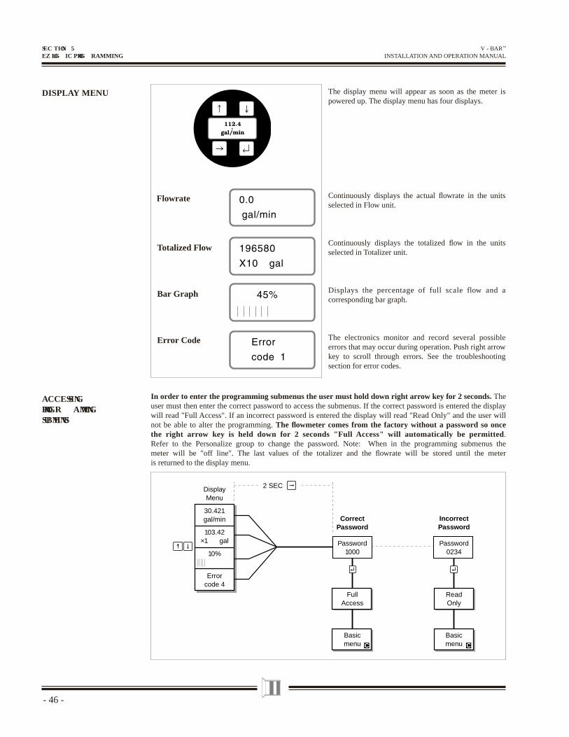
DISPLAY MENU The display menu will appear as soon as the meter is powered up. The display menu has four displays.
Continuously displays the actual fl owrate in the units selected in Flow unit.
Continuously displays the totalized fl ow in the units selected in Totalizer unit.
Displays the percentage of full scale flow and a corresponding bar graph.
The electronics monitor and record several possible errors that may occur during operation. Push right arrow key to scroll through errors. See the troubleshooting section for error codes.
Flowrate
Totalized Flow
Error Code
Bar Graph
In order to enter the programming submenus the user must hold down right arrow key for 2 seconds. The user must then enter the correct password to access the submenus. If the correct password is entered the display will read "Full Access". If an incorrect password is entered the display will read "Read Only" and the user will not be able to alter the programming. The fl owmeter comes from the factory without a password so once the right arrow key is held down for 2 seconds "Full Access" will automatically be permitted. Refer to the Personalize group to change the password. Note: When in the programming submenus the meter will be "off line". The last values of the totalizer and the fl owrate will be stored until the meter is returned to the display menu.
ACCESSINGPROGR AMMING SUBMENUS
SEC TION 5EZ LOG IC PROG RAMMING
- 47-
V - BAR™ INSTALLATION AND OPERATION MANUAL
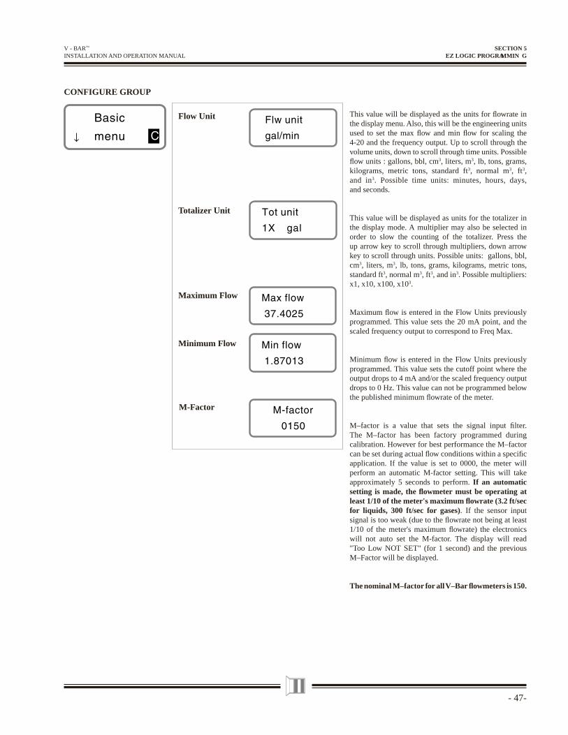
CONFIGURE GROUP
This value will be displayed as the units for fl owrate in the display menu. Also, this will be the engineering units used to set the max fl ow and min fl ow for scaling the 4-20 and the frequency output. Up to scroll through the volume units, down to scroll through time units. Possible fl ow units : gallons, bbl, cm3, liters, m3, lb, tons, grams, kilograms, metric tons, standard ft3, normal m3, ft3, and in3. Possible time units: minutes, hours, days, and seconds.
This value will be displayed as units for the totalizer in the display mode. A multiplier may also be selected in order to slow the counting of the totalizer. Press the up arrow key to scroll through multipliers, down arrow key to scroll through units. Possible units: gallons, bbl, cm3, liters, m3, lb, tons, grams, kilograms, metric tons, standard ft3, normal m3, ft3, and in3. Possible multipliers: x1, x10, x100, x103.
Maximum fl ow is entered in the Flow Units previously programmed. This value sets the 20 mA point, and the scaled frequency output to correspond to Freq Max.
Minimum fl ow is entered in the Flow Units previously programmed. This value sets the cutoff point where the output drops to 4 mA and/or the scaled frequency output drops to 0 Hz. This value can not be programmed below the published minimum fl owrate of the meter.
M–factor is a value that sets the signal input fi lter. The M–factor has been factory programmed during calibration. However for best performance the M–factor can be set during actual fl ow conditions within a specifi c application. If the value is set to 0000, the meter will perform an automatic M-factor setting. This will take approximately 5 seconds to perform. If an automatic setting is made, the fl owmeter must be operating at least 1/10 of the meter's maximum fl owrate (3.2 ft/sec for liquids, 300 ft/sec for gases). If the sensor input signal is too weak (due to the fl owrate not being at least 1/10 of the meter's maximum fl owrate) the electronics will not auto set the M-factor. The display will read "Too Low NOT SET" (for 1 second) and the previous M–Factor will be displayed.
The nominal M–factor for all V–Bar fl owmeters is 150.
Minimum Flow
Maximum Flow
Totalizer Unit
Flow Unit
M-Factor
SECTION 5EZ LOGIC PROGRAMMIN G
- 48 -
V - BAR™ INSTALLATION AND OPERATION MANUAL
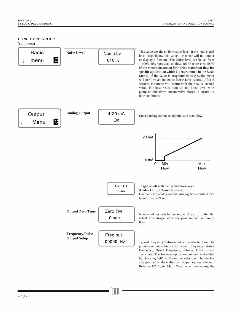
CONFIGURE GROUP(continued)
Frequency/PulseOutput Setup
This value sets the no fl ow cutoff level. If the input signal level drops below this value, the meter will not output or display a fl owrate. The Noise level can be set from 1-100%. 0% represents no fl ow, 100 % represents 100% of the meter's maximum fl ow. (Not maximum fl ow for specifi c application which is programmed in the Basic Menu). If the value is programmed as 000, the meter will perform an automatic Noise Level setting. After 5 seconds the meter will return with the new calculated value. For best result auto set the noise level with pump on and down stream valve closed to ensure no fl ow conditions.
Linear analog output set by min. and max. fl ow.
Noise Level
Output Zero Time
Toggle on/off with the up and down keys. Analog Output Time ConstantDampens the analog output. Analog time constant can be set from 0-99 sec.
Number of seconds before output drops to 0 after the actual fl ow drops below the programmed, minimum fl ow.
Type of Frequency/Pulse output can be selected here. The possible output options are: Scaled Frequency, Vortex Frequency, Direct Frequency, Pulse –, Pulse +, and Transition. The frequency/pulse output can be disabled by choosing "off" as the output selection. The display changes below depending on output option selected. Refer to EZ Logic Map. Note: When connecting the
Analog Output
SECTION 5EZ LOGIC PROGRAMMIN G
- 49-
V - BAR™ INSTALLATION AND OPERATION MANUAL
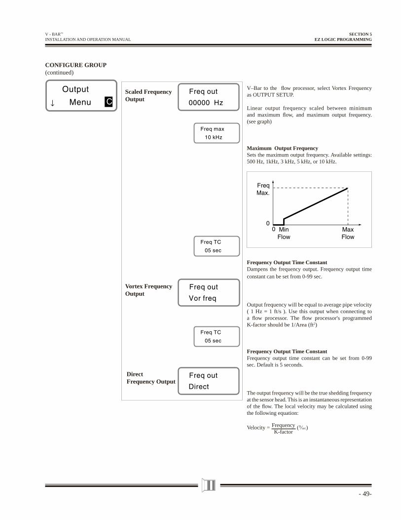
V–Bar to the fl ow processor, select Vortex Frequency as OUTPUT SETUP.
Linear output frequency scaled between minimum and maximum fl ow, and maximum output frequency. (see graph)
Maximum Output FrequencySets the maximum output frequency. Available settings: 500 Hz, 1kHz, 3 kHz, 5 kHz, or 10 kHz.
Frequency Output Time ConstantDampens the frequency output. Frequency output time constant can be set from 0-99 sec.
Output frequency will be equal to average pipe velocity ( 1 Hz = 1 ft/s ). Use this output when connecting to a fl ow processor. The fl ow processor's programmed K-factor should be 1/Area (ft2)
Frequency Output Time ConstantFrequency output time constant can be set from 0-99 sec. Default is 5 seconds.
The output frequency will be the true shedding frequency at the sensor head. This is an instantaneous representation of the fl ow. The local velocity may be calculated using the following equation:
Velocity = FrequencyK-factor
( ft⁄sec )
CONFIGURE GROUP(continued)
DirectFrequency Output
Vortex FrequencyOutput
Scaled FrequencyOutput
SECTION 5EZ LOGIC PROGRAMMING
- 50 -
V - BAR™ INSTALLATION AND OPERATION MANUAL
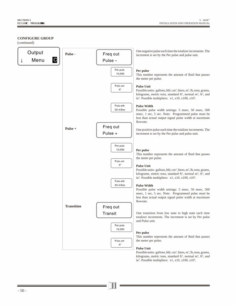
CONFIGURE GROUP(continued)
One negative pulse each time the totalizer increments. The increment is set by the Per pulse and pulse unit.
Per pulseThis number represents the amount of fl uid that passes the meter per pulse.
Pulse UnitPossible units: gallons, bbl, cm3, liters, m3, lb, tons, grams, kilograms, metric tons, standard ft3, normal m3, ft3, and in3. Possible multipliers: x1, x10, x100, x103.
Pulse WidthPossible pulse width settings: 5 msec, 50 msec, 500 msec, 1 sec, 5 sec. Note: Programmed pulse must be less than actual output signal pulse width at maximum fl owrate.
One positive pulse each time the totalizer increments. The increment is set by the Per pulse and pulse unit.
Per pulseThis number represents the amount of fl uid that passes the meter per pulse.
Pulse UnitPossible units: gallons, bbl, cm3, liters, m3, lb, tons, grams, kilograms, metric tons, standard ft3, normal m3, ft3, and in3. Possible multipliers: x1, x10, x100, x103.
Pulse WidthPossible pulse width settings: 5 msec, 50 msec, 500 msec, 1 sec, 5 sec. Note: Programmed pulse must be less than actual output signal pulse width at maximum fl owrate.
One transition from low state to high state each time totalizer increments. The increment is set by Per pulse and Pulse unit.
Per pulseThis number represents the amount of fl uid that passes the meter per pulse.
Pulse UnitPossible units: gallons, bbl, cm3, liters, m3, lb, tons, grams, kilograms, metric tons, standard ft3, normal m3, ft3, and in3. Possible multipliers: x1, x10, x100, x103.
Pulse -
Pulse +
Transition
SECTION 5EZ LOGIC PROGRAMMING
- 51-
V - BAR™ INSTALLATION AND OPERATION MANUAL
CONFIGURE GROUP(continued)
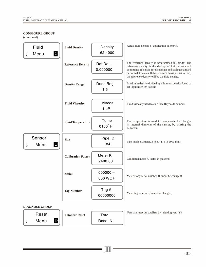
Actual fl uid density of application in lbm/ft3.
The reference density is programmed in lbm/ft3. The reference density is the density of fl uid at standard conditions. It is used for displaying and scaling standard or normal fl owrates. If the reference density is set to zero, the reference density will be the fl uid density.
Maximum density divided by minimum density. Used to set input fi lter. (M-factor)
Fluid viscosity used to calculate Reynolds number.
The temperature is used to compensate for changes in internal diameter of the sensor, by shifting the K-Factor.
Pipe inside diameter, 3 to 80" (75 to 2000 mm).
Calibrated meter K-factor in pulses/ft.
Meter Body serial number. (Cannot be changed)
Meter tag number. (Cannot be changed)
Fluid Density
Reference Density
Density Range
DIAGNOSE GROUP
Fluid Temperature
Calibration Factor
Size
Serial
Tag Number
Totalizer Reset
Fluid Viscosity
User can reset the totalizer by selecting yes. (Y)
SECTION 5EZ LOGIC PROGRAMMIN G
- 52 -
V - BAR™ INSTALLATION AND OPERATION MANUAL
DIAGNOSE GROUP(continued)
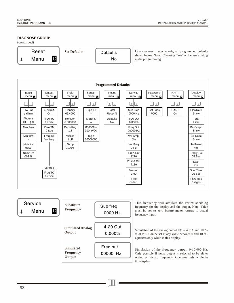
This frequency will simulate the vortex shedding frequency for the display and the output. Note: Value must be set to zero before meter returns to actual frequency input.
Simulation of the analog output 0% = 4 mA and 100% = 20 mA. Can be set at any value between 0 and 100%. Operates only while in this display.
Simulation of the frequency output, 0-10,000 Hz. Only possible if pulse output is selected to be either scaled or vortex frequency. Operates only while in this display.
SubstituteFrequency
Simulated AnalogOutput
SimulatedFrequencyOutput
User can reset meter to original programmed defaults shown below. Note: Choosing "Yes" will erase existing meter programming.
Set Defaults
Programmed Defaults
Basicmenu
Flw unitgal/min
Outputmenu
Fluidmenu
Sensormenu
Resetmenu
Servicemenu
Passwordmenu
HARTmenu
Displaymenu
Tag #00000000
Tot unit×1 gal
Max flow–
Min flow–
M-factor0150
Noise Lv003 %
4-20 mAOn
4-20 TC05 Sec
Zero TM0 Sec
Freq outVor freq
Vor freq
Freq TC05 Sec
Density62.4000
Ref Den0.000000
Dens Rng1.5
Viscos1 cP
Temp0100°F
Pipe ID–
Meter K–
000000 –000 WO#
TotalReset N
DefaultsNo
Set Pass0000
HARTOn
Sub Freq0000 Hz
4-20 Out0.000%
Vor Ampl0%
Vor Freq0 Hz
4 mA Cnt1270
20 mA Cnt7150
Version3.00
Errorcode 1
Freq Out00000 Hz
FlowRateShow
TotalHide
Err CodeShow
TotResetYes
Dsply TC05 Sec
ScanOn
ScanTime05 Sec
Flow Res8 digits
BarGraphShow
SECT ION 5EZ LOGIC PROGRAMMIN G
- 53-
V - BAR™ INSTALLATION AND OPERATION MANUAL
DIAGNOSE GROUP(continued)
Condulet Head(Field Wiring Side)
Multimeter
Power Supply
Input signal level 0-100% of meter's maximum.(Not maximum fl ow of specifi c application which is programmed in the Basic Menu).
The raw input frequency from the sensor.
Sets the # of units the microprocessor must send to the current output circuit to generate 4 mA.
Sets the # of units the microprocessor must send to the current output circuit to generate 20 mA.
Wiring diagram for 4-20 mA output calibration To calibrate mA counts, move display to 4 mA count , press enter. Read current value from multimeter. Value should be within ±0.012 mA. If value deviates by more than ±0.012 mA, adjust microprocessor count until multimeter value equals 4 mA, press enter. Repeat steps for 20 mA count.
Revision of the software used is displayed.
Displays current errors. Once error condition no longer exists, error code is cleared. Push right arrow key to scroll through arrows. See trouble shooting section for error code descriptions.
Version
2.10
Error
code 1
20mA CalibrationValue
4 mA CalibrationValue
Input SignalAmplitude
Vortex Frequency
Software Revision
Self Diagnostics
SECTION 5EZ LOGIC PROGRAMMIN G
- 54 -
V - BAR™ INSTALLATION AND OPERATION MANUAL
Set Pass
1000
PERSONALIZE GROUP
HART
On
Set New Password
HARTEnable/Disable
HART
Menu P
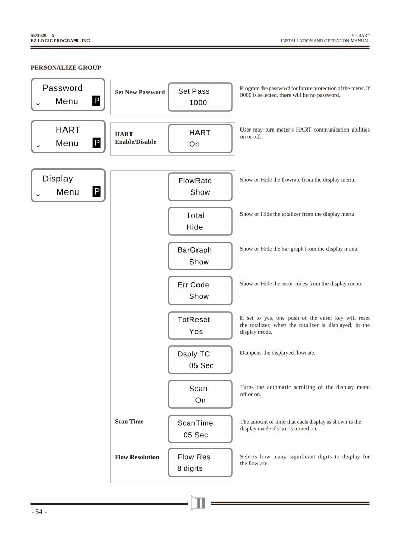
Program the password for future protection of the meter. If 0000 is selected, there will be no password.
User may turn meter’s HART communication abilities on or off.
Show or Hide the fl owrate from the display menu.
Show or Hide the totalizer from the display menu.
Show or Hide the bar graph from the display menu.
Show or Hide the error codes from the display menu.
If set to yes, one push of the enter key will reset the totalizer, when the totalizer is displayed, in the display mode.
Dampens the displayed fl owrate.
Turns the automatic scrolling of the display menu off or on.
The amount of time that each display is shown is the display mode if scan is turned on.
Selects how many significant digits to display for the fl owrate.
Flow Res
8 digits
Flow Resolution
ScanTime
05 Sec
Scan Time
Scan
On
Dsply TC
05 Sec
TotReset
Yes
Err Code
Show
Total
Hide
FlowRate
Show
Display
Menu P
Password
Menu P
SECTION 5EZ LOGIC PROGRAMM ING
- 55-
V - BAR™ INSTALLATION AND OPERATION MANUAL
EXITINGPROGRAMMING SUB-MENUS
30.421
gal/min
103.42
x1 gal
10%
Error
code 4
Display
Menu
SavChng?
Yes
Exit
No
Basic
menu
Fluid
menu
Service
menu
Reset
menu
HART
menu
Display
menu
Password
menu
Sensor
menuC C C C D D P P P
Output
menu
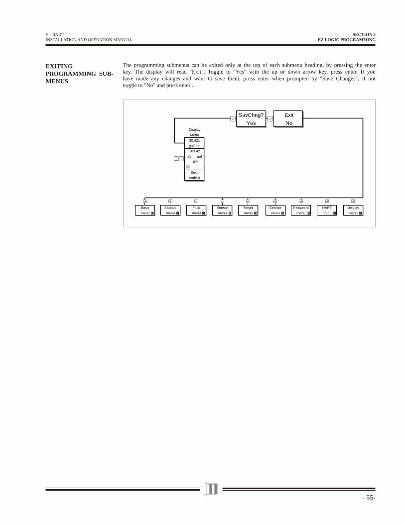
The programming submenus can be exited only at the top of each submenu heading, by pressing the enter key. The display will read "Exit". Toggle to "Yes" with the up or down arrow key, press enter. If you have made any changes and want to save them, press enter when prompted by "Save Changes", if not toggle to "No" and press enter .
SECTION 5EZ LOGIC PROGRAMMING
- 56 -
V - BAR™ INSTALLATION AND OPERATION MANUAL
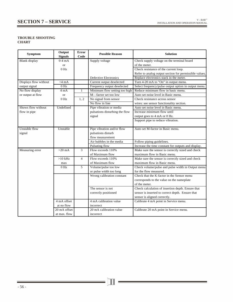
TROUBLE SHOOTING CHART
SECTION 7 – SERVICE
Blank display
Displays flow withoutoutput signalNo flow displayor output at flow
Shows flow withoutflow in pipe
Unstable flowsignal
Measuring error
0-4 mAor
0 Hz
<4 mA0 Hz4 mA
or0 Hz
Undefined
Unstable
>20 mA
>10 kHzmax0 Hz
4 mA offsetat no flow
20 mA offsetat max. flow
1
1, 2
3
4
5
Supply voltage
Defective ElectronicsCurrent output deselectedFrequency output deselectedMinimum flow setting too highM—factor set too lowNo signal from sensorNo flow in linePipe vibration or mediapulsations disturbing the flowsignal
Pipe vibration and/or flowpulsations disturbflow measurementAir bubbles in the mediaPulsating flowFlow exceeds 110%of Maximum flowFlow exceeds 110%of Maximum flowVolume/pulse too lowor pulse width too longWrong calibration constant
The sensor is notcorrectly positioned
4 mA calibration value incorrect20 mA calibration valueincorrect
Check supply voltage on the terminal boardof the meter.Check resistance of the current loop.Refer to analog output section for permissible values.Replace electronics stack in the meter.Turn 4-20 mA to "On" in output menu.Select frequency/pulse output option in output menu. Reduce minimum flow in basic menu.Auto set noise level in Basic menu.Check resistance across sensorwires: see sensor functionality section.Auto set noise level in Basic menu.Increase minimum flow untiloutput goes to 4 mA or 0 Hz.Support pipe to reduce vibration.
Auto set M-factor in Basic menu.
Follow piping guidelines.Increase the time constant for outputs and display.Make sure the sensor is correctly sized and checkmaximum flow in Basic menu.Make sure the sensor is correctly sized and checkmaximum flow in Basic menu.Check volume/pulse and pulse width in Output menufor the flow measured.Check that the K-factor in the Sensor menucorresponds to the value on the nameplateof the meter.Check calculation of insertion depth. Ensure thatsensor is inserted to correct depth. Ensure thatsensor is aligned correctly.Calibrate 4 mA point in Service menu.
Calibrate 20 mA point in Service menu.
Symptom OutputSignals
ErrorCode
Possible Reason Solution
- 57-
V - BAR™ INSTALLATION AND OPERATION MANUAL
SECTION 7SERVICE
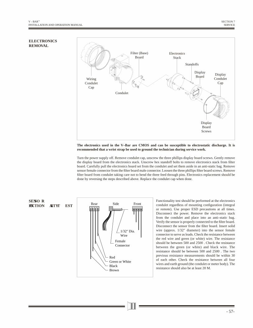
ELECTRONICSREMOVAL
DisplayCondulet
Cap
DisplayBoard
ElectronicsStack
Standoffs
Condulet
WiringCondulet
Cap
DisplayBoardScrews
Filter (Base)Board
The electronics used in the V–Bar are CMOS and can be susceptible to electrostatic discharge. It is recommended that a wrist strap be used to ground the technician during service work.
Turn the power supply off. Remove condulet cap, unscrew the three phillips display board screws. Gently remove the display board from the electronics stack. Unscrew hex standoff bolts to remove electronics stack from fi lter board. Carefully pull the electronics board set from the condulet and set them aside in an anti-static bag. Remove sensor female connector from the fi lter board male connector. Loosen the three phillips fi lter board screws. Remove fi lter board from condulet taking care not to bend the three feed through pins. Electronics replacement should be done by reversing the steps described above. Replace the condulet cap when done.
SENSO RFUNCTION ALITY T EST
Functionality test should be performed at the electronics condulet regardless of mounting confi guration (integral or remote). Use proper ESD precautions at all times. Disconnect the power. Remove the electronics stack from the condulet and place into an anti–static bag. Verify the sensor is properly connected to the fi lter board. Disconnect the sensor from the fi lter board. Insert solid wire (approx. 1/32" diameter) into the sensor female connector to serve as leads. Check the resistance between the red wire and green (or white) wire. The resistance should be between 500 and 2500 . Check the resistance between the green (or white) and black wire. The resistance should be between 500 and 2500 . The two previous resistance measurements should be within 30 of each other. Check the resistance between all four wires and earth ground (the condulet or meter body). The resistance should also be at least 20 M.
Rear
RedGreen or WhiteBlackBrown
Side
FemaleConnector
1/32" Dia.Wire
Front
- 58 -
V - BAR™ INSTALLATION AND OPERATION MANUAL
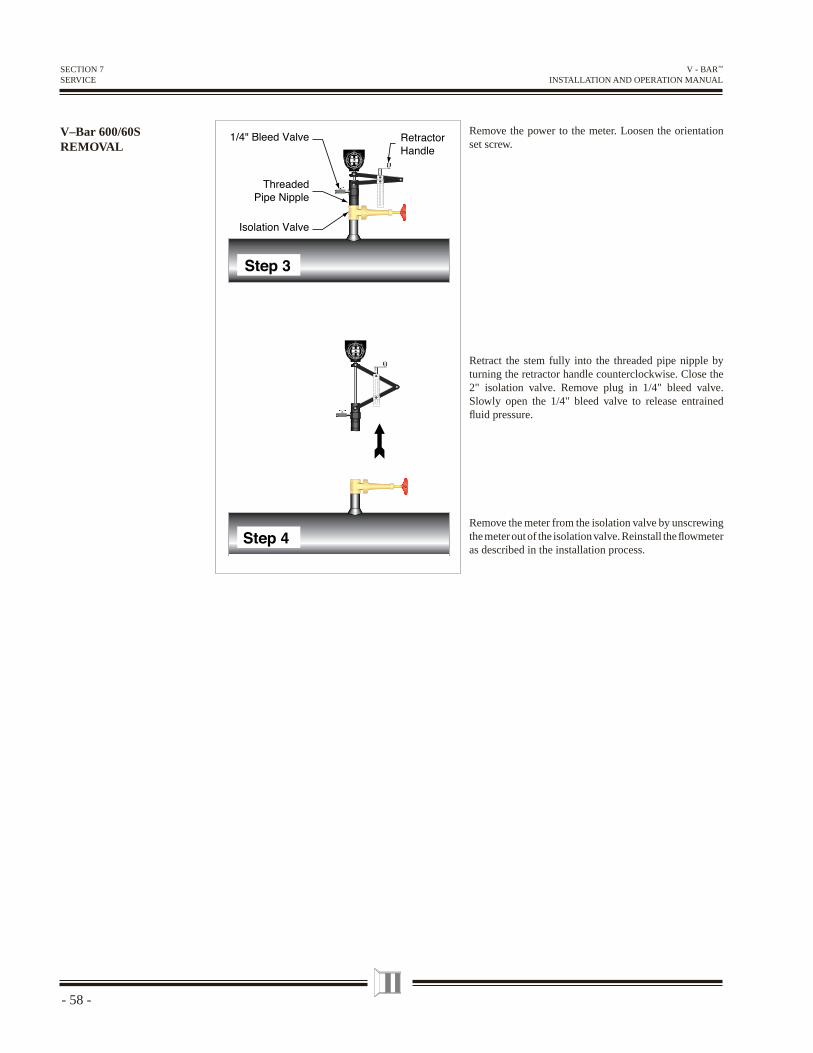
V–Bar 600/60S REMOVAL
Remove the power to the meter. Loosen the orientation set screw.
Retract the stem fully into the threaded pipe nipple by turning the retractor handle counterclockwise. Close the 2" isolation valve. Remove plug in 1/4" bleed valve. Slowly open the 1/4" bleed valve to release entrained fl uid pressure.
Remove the meter from the isolation valve by unscrewing the meter out of the isolation valve. Reinstall the fl owmeter as described in the installation process.
SECTION 7SERVICE
- 59-
V - BAR™ INSTALLATION AND OPERATION MANUAL
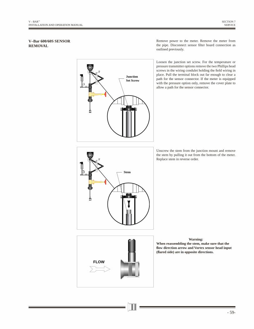
V–Bar 600/60S SENSOR REMOVAL
FLOW
112.4
gal/min
E MCO
EM
CO
EMCO
EM
CO
Stem
112.4
gal/min
E MCO
EM
CO
EMCO
EM
CO
JunctionSet Screw
SECTION 7SERVICE
Remove power to the meter. Remove the meter from the pipe. Disconnect sensor fi lter board connection as outlined previously.
Loosen the junction set screw. For the temperature or pressure transmitter options remove the two Phillips head screws in the wiring condulet holding the fi eld wiring in place. Pull the terminal block out far enough to clear a path for the sensor connector. If the meter is equipped with the pressure option only, remove the cover plate to allow a path for the sensor connector.
Unscrew the stem from the junction mount and remove the stem by pulling it out from the bottom of the meter. Replace stem in reverse order.
Warning:When reassembling the stem, make sure that the fl ow direction arrow and Vortex sensor head input (fl ared side) are in opposite directions.
- 60 -
V - BAR™ INSTALLATION AND OPERATION MANUAL
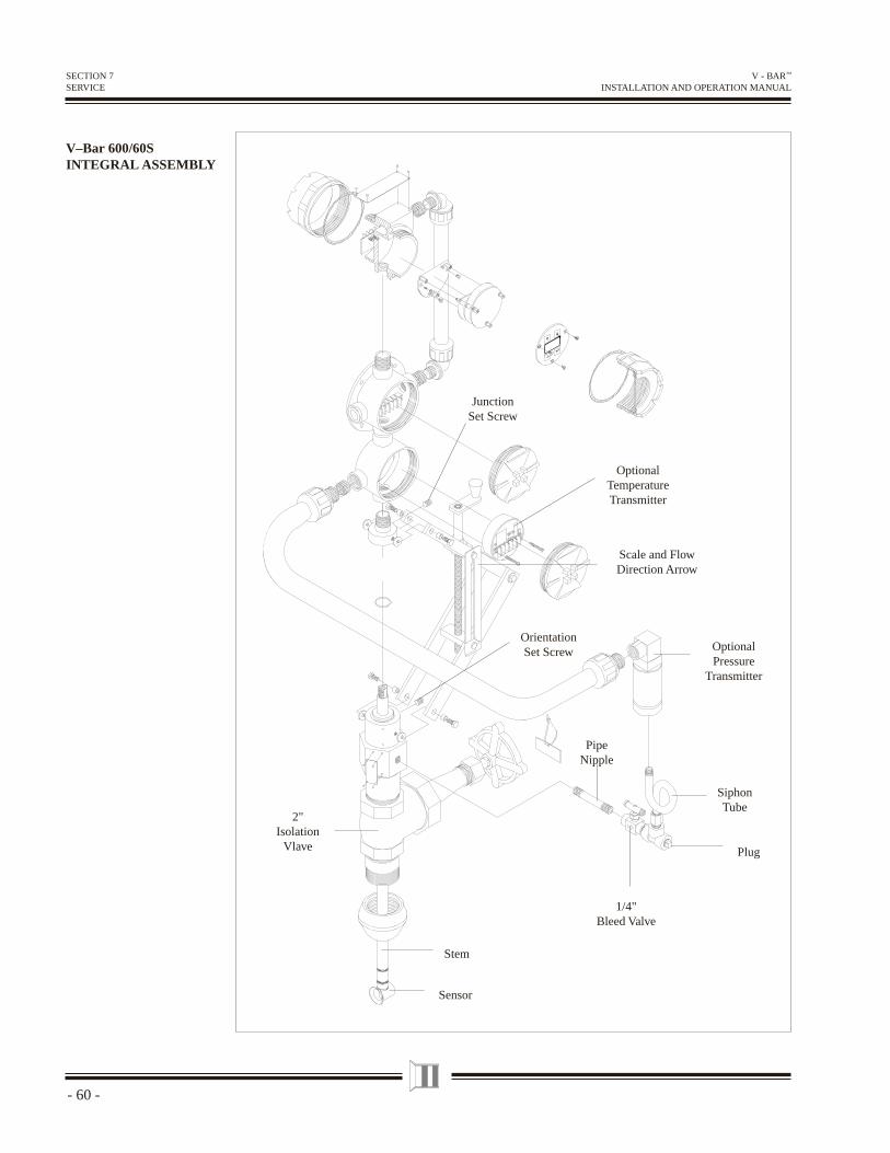
V–Bar 600/60S INTEGRAL ASSEMBLY
SECTION 7SERVICE
1/4"Bleed Valve
SiphonTube
2"Isolation
Vlave
OrientationSet Screw Optional
PressureTransmitter
JunctionSet Screw
Scale and FlowDirection Arrow
PipeNipple
Sensor
Stem
Plug
OptionalTemperatureTransmitter
- 61-
V - BAR™ INSTALLATION AND OPERATION MANUAL
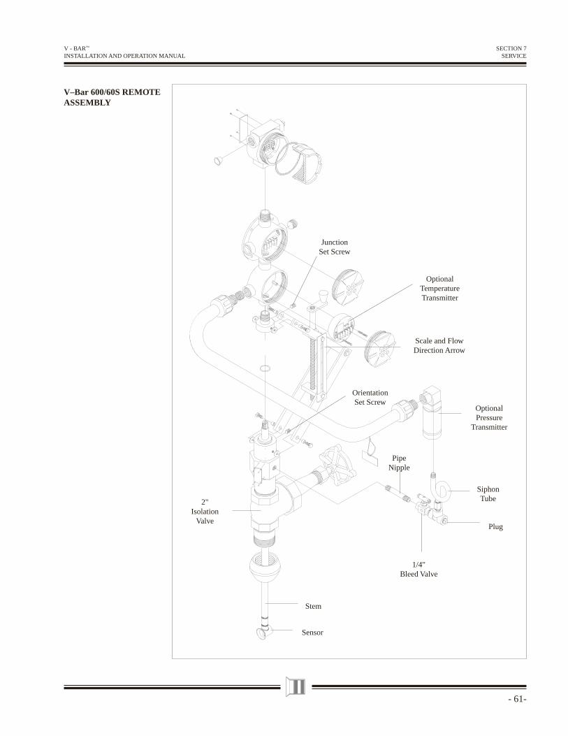
V–Bar 600/60S REMOTE ASSEMBLY
SECTION 7SERVICE
JunctionSet Screw
Scale and FlowDirection Arrow
OrientationSet Screw
OptionalPressure
Transmitter
SiphonTube
1/4"Bleed Valve
PipeNipple
2"Isolation
Valve
Sensor
Stem
Plug
OptionalTemperatureTransmitter
- 62 -
V - BAR™ INSTALLATION AND OPERATION MANUAL
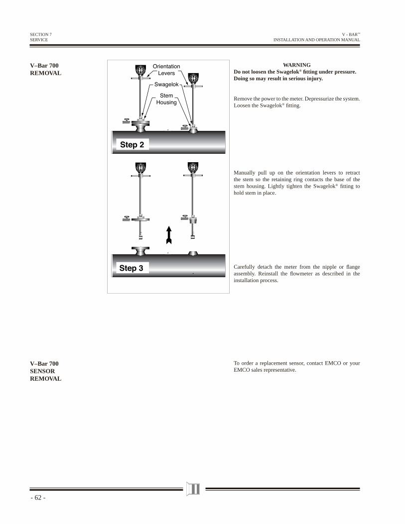
WARNINGDo not loosen the Swagelok® fi tting under pressure. Doing so may result in serious injury.
Remove the power to the meter. Depressurize the system. Loosen the Swagelok® fi tting.
Manually pull up on the orientation levers to retract the stem so the retaining ring contacts the base of the stem housing. Lightly tighten the Swagelok® fi tting to hold stem in place.
Carefully detach the meter from the nipple or fl ange assembly. Reinstall the fl owmeter as described in the installation process.
V–Bar 700 REMOVAL
To order a replacement sensor, contact EMCO or your EMCO sales representative.
V–Bar 700 SENSOR REMOVAL
SECTION 7SERVICE
- 63-
V - BAR™ INSTALLATION AND OPERATION MANUAL
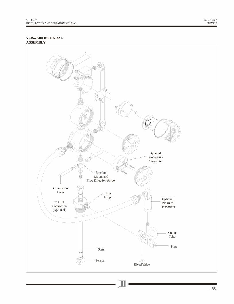
V–Bar 700 INTEGRAL ASSEMBLY
SECTION 7SERVICE
OptionalPressure
Transmitter
SiphonTube
Plug
1/4"Bleed Valve
Sensor
Stem
PipeNipple
2" NPTConnection(Optional)
OrientationLever
JunctionMount and
Flow Direction Arrow
OptionalTemperatureTransmitter
- 64 -
V - BAR™ INSTALLATION AND OPERATION MANUAL
V–Bar 700 REMOTE ASSEMBLY
SECTION 7SERVICE
OrientationLever
JunctionMount and
Flow Direction Arrow
OptionalPressure
Transmitter
SiphonTube
Plug
1/4"Bleed ValveSensor
Stem
OptionalTemperatureTransmitter
2" NPTConnection(Optional)
PipeNipple
- 65-
V - BAR™ INSTALLATION AND OPERATION MANUAL
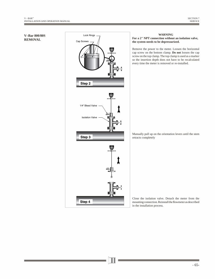
V–Bar 800/80S REMOVAL
WARNINGFor a 2" NPT connection without an isolation valve, the system needs to be depressurized.
Remove the power to the meter. Loosen the horizontal cap screw on the bottom clamp. Do not loosen the cap screw on the top clamp. The top clamp is used as a marker so the insertion depth does not have to be recalculated every time the meter is removed or re-installed.
Manually pull up on the orientation levers until the stem retracts completely
Close the isolation valve. Detach the meter from the mounting connection. Reinstall the fl owmeter as described in the installation process.
SECTION 7SERVICE
- 66 -
V - BAR™ INSTALLATION AND OPERATION MANUAL
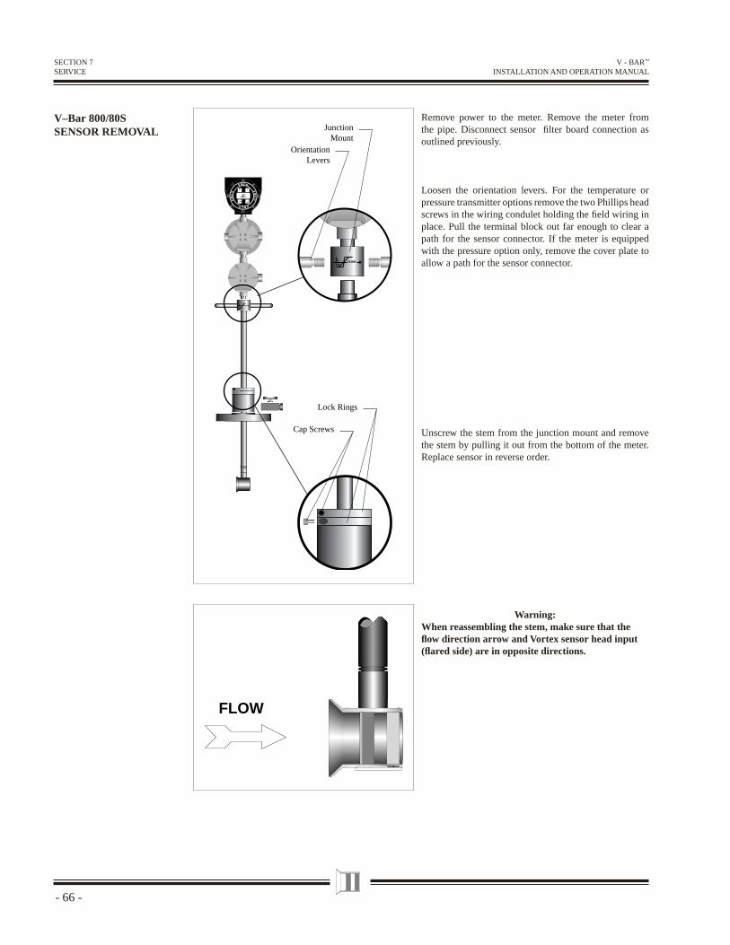
V–Bar 800/80S SENSOR REMOVAL
Cap Screws
Lock Rings
112.4
gal/min
EMCO
EM
CO
EMCO
EM
CO
EM
COFLOW
OrientationLevers
JunctionMount
EM
COFLOW
FLOW
SECTION 7SERVICE
Remove power to the meter. Remove the meter from the pipe. Disconnect sensor fi lter board connection as outlined previously.
Loosen the orientation levers. For the temperature or pressure transmitter options remove the two Phillips head screws in the wiring condulet holding the fi eld wiring in place. Pull the terminal block out far enough to clear a path for the sensor connector. If the meter is equipped with the pressure option only, remove the cover plate to allow a path for the sensor connector.
Unscrew the stem from the junction mount and remove the stem by pulling it out from the bottom of the meter. Replace sensor in reverse order.
Warning:When reassembling the stem, make sure that the fl ow direction arrow and Vortex sensor head input (fl ared side) are in opposite directions.
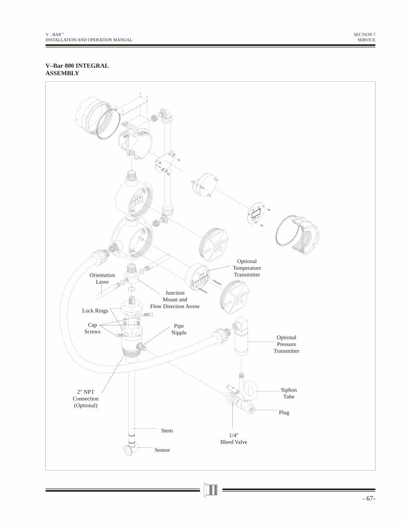
- 67-
V - BAR™ INSTALLATION AND OPERATION MANUAL
V–Bar 800 INTEGRAL ASSEMBLY
SECTION 7SERVICE
Stem
JunctionMount and
Flow Direction Arrow
OrientationLever
OptionalTemperatureTransmitter
OptionalPressure
Transmitter
SiphonTube
Plug
Lock Rings
CapScrews
2" NPTConnection(Optional)
PipeNipple
Sensor
1/4"Bleed Valve
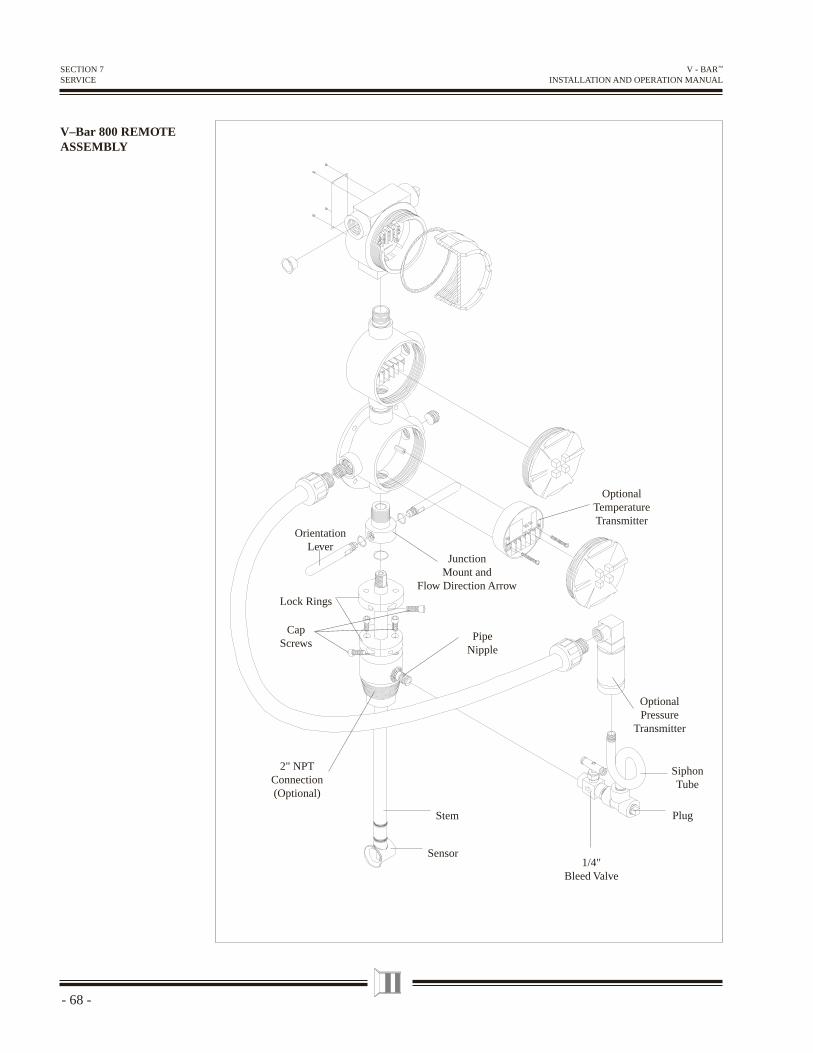
- 68 -
V - BAR™ INSTALLATION AND OPERATION MANUAL
V–Bar 800 REMOTE ASSEMBLY
SECTION 7SERVICE
PipeNipple
SiphonTube
1/4"Bleed Valve
Plug
Sensor
Stem
OptionalPressure
Transmitter
OptionalTemperatureTransmitter
JunctionMount and
Flow Direction Arrow
OrientationLever
Lock Rings
CapScrews
2" NPTConnection(Optional)
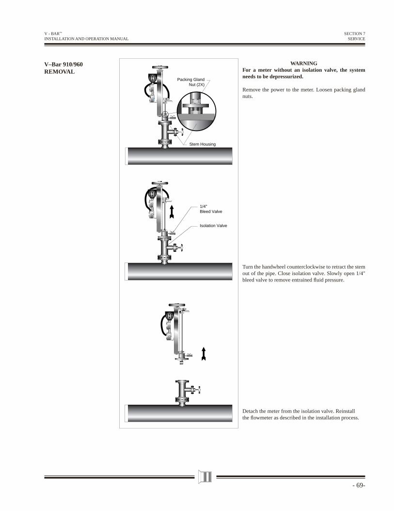
- 69-
V - BAR™ INSTALLATION AND OPERATION MANUAL
V–Bar 910/960 REMOVAL
WARNINGFor a meter without an isolation valve, the system needs to be depressurized.
Remove the power to the meter. Loosen packing gland nuts.
Turn the handwheel counterclockwise to retract the stem out of the pipe. Close isolation valve. Slowly open 1/4" bleed valve to remove entrained fl uid pressure.
Detach the meter from the isolation valve. Reinstall the fl owmeter as described in the installation process.
1/4"Bleed Valve
Isolation Valve
112.4
gal/min
E MCO
EM
CO
EMCO
EM
CO
112.4
gal/min
E MCO
EM
CO
EMCO
EM
CO
112.4
gal/min
E MCO
EM
CO
EMCO
EM
CO Packing Gland
Nut (2X)
Stem Housing
SECTION 7SERVICE
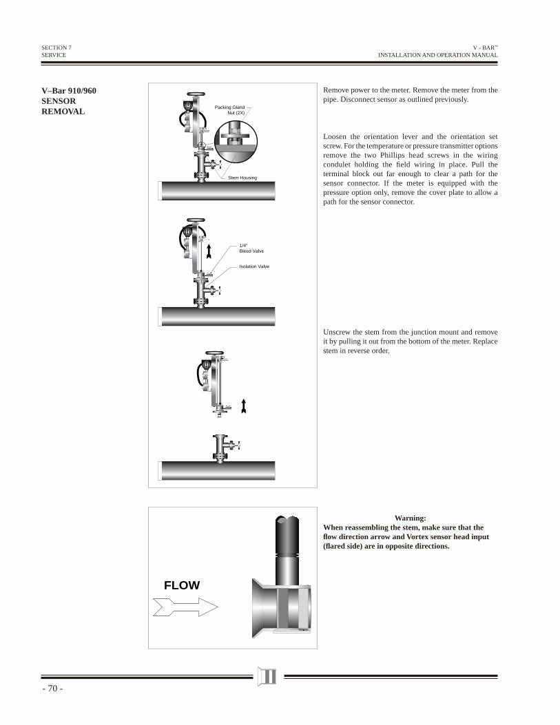
- 70 -
V - BAR™ INSTALLATION AND OPERATION MANUAL
Remove power to the meter. Remove the meter from the pipe. Disconnect sensor as outlined previously.
Loosen the orientation lever and the orientation set screw. For the temperature or pressure transmitter options remove the two Phillips head screws in the wiring condulet holding the fi eld wiring in place. Pull the terminal block out far enough to clear a path for the sensor connector. If the meter is equipped with the pressure option only, remove the cover plate to allow a path for the sensor connector.
Unscrew the stem from the junction mount and remove it by pulling it out from the bottom of the meter. Replace stem in reverse order.
Warning:When reassembling the stem, make sure that the fl ow direction arrow and Vortex sensor head input (fl ared side) are in opposite directions.
V–Bar 910/960 SENSOR REMOVAL
FLOW
1/4"Bleed Valve
Isolation Valve
112.4
gal/min
E MCO
EM
CO
EMCO
EM
CO
112.4
gal/min
E MCO
EM
CO
EMCO
EM
CO
112.4
gal/min
E MCO
EM
CO
EMCO
EM
CO Packing Gland
Nut (2X)
Stem Housing
SECTION 7SERVICE
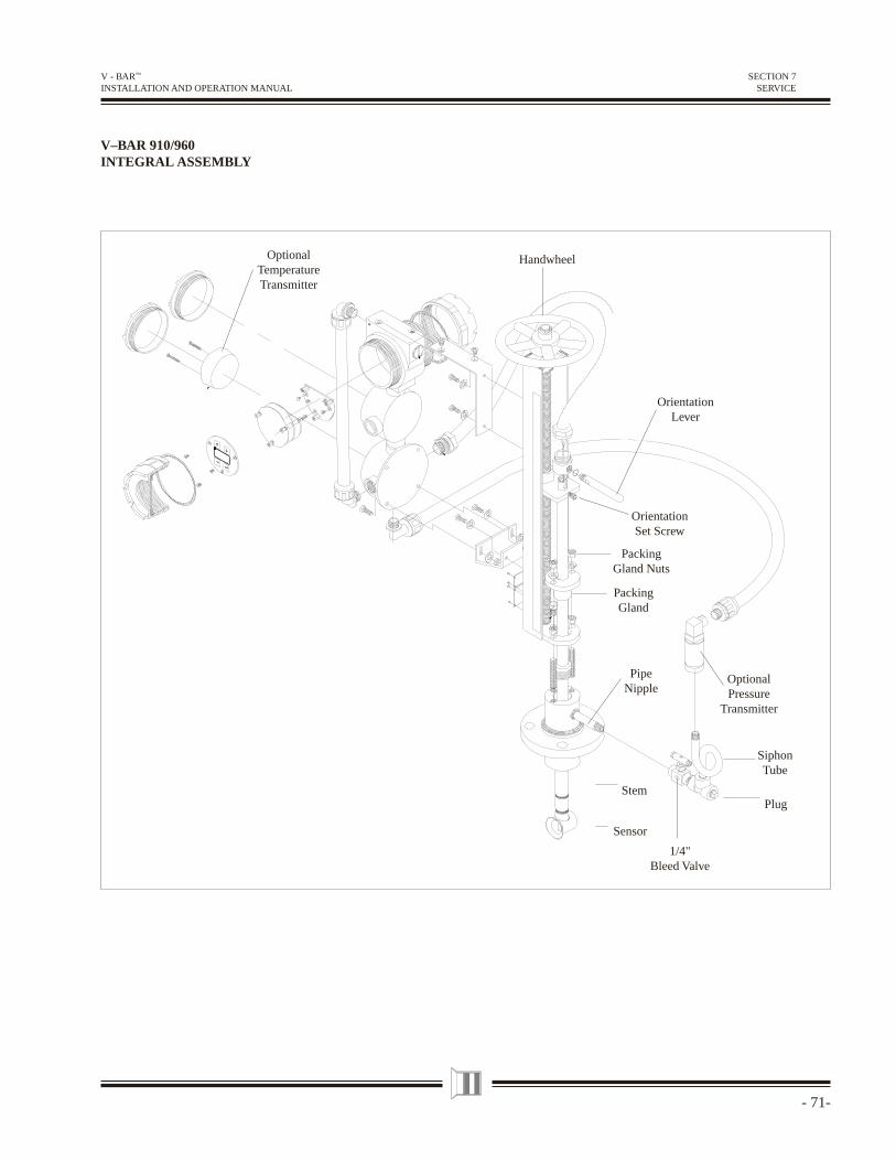
- 71-
V - BAR™ INSTALLATION AND OPERATION MANUAL
SECTION 7SERVICE
V–BAR 910/960INTEGRAL ASSEMBLY
Handwheel
Plug
SiphonTube
1/4"Bleed Valve
Sensor
Stem
PipeNipple
OptionalPressure
Transmitter
PackingGland
PackingGland Nuts
OrientationSet Screw
OrientationLever
OptionalTemperatureTransmitter
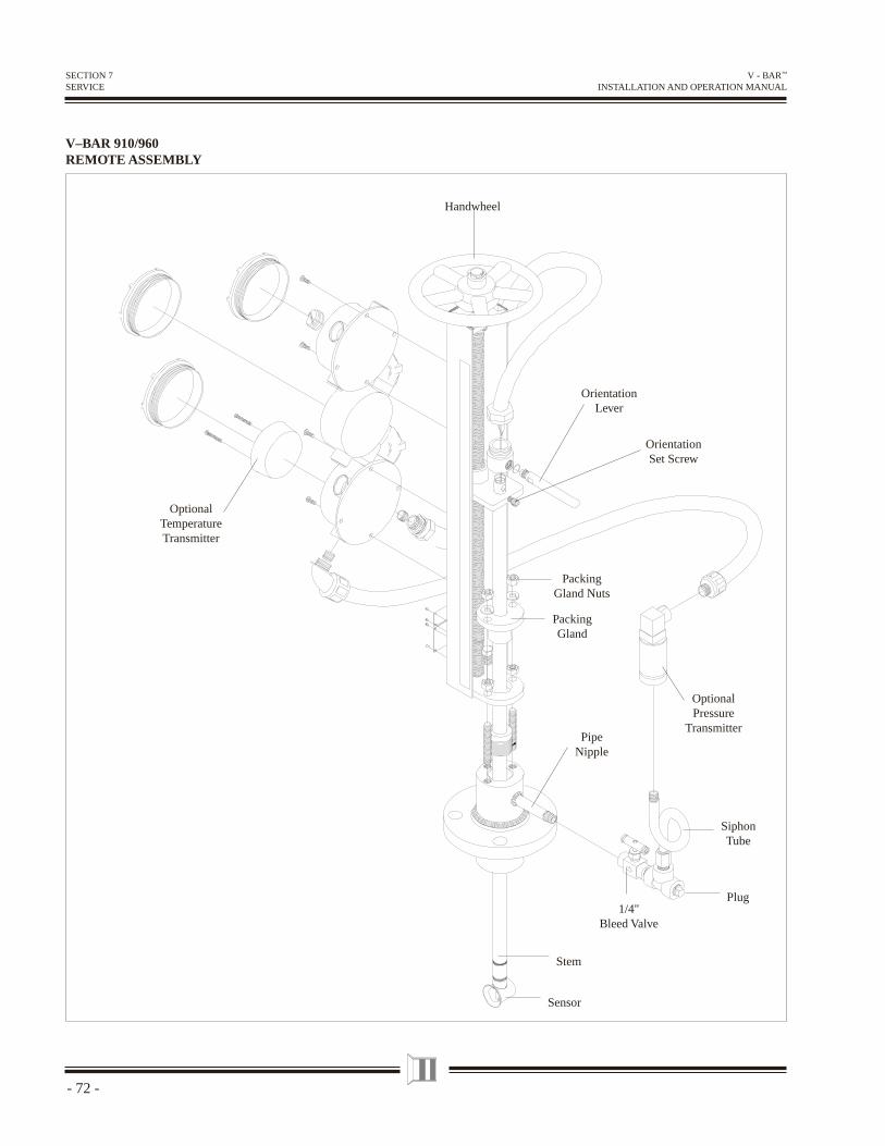
- 72 -
V - BAR™ INSTALLATION AND OPERATION MANUAL
SECTION 7SERVICE
V–BAR 910/960REMOTE ASSEMBLY
Sensor
Stem
1/4"Bleed Valve
Plug
SiphonTube
OptionalPressure
TransmitterPipe
Nipple
PackingGland
Packing Gland Nuts
OptionalTemperatureTransmitter
Handwheel
OrientationLever
OrientationSet Screw
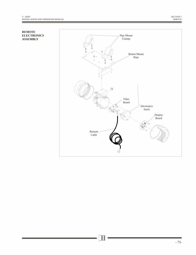
- 73-
V - BAR™ INSTALLATION AND OPERATION MANUAL
REMOTEELECTRONICSASSEMBLY
SECTION 7SERVICE
Pipe MountClamps
Remot MountPlate
FilterBoard
DisplayBoard
RemoteCable
ElectronicsStack
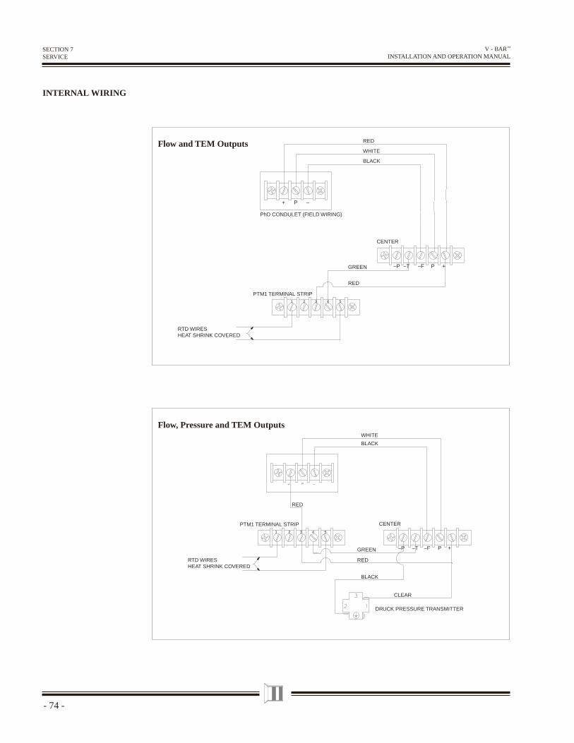
- 74 -
V - BAR™ INSTALLATION AND OPERATION MANUAL
–P –T –F P +
CLEAR
RED
WHITE
BLACK
BLACK
GREEN
RED
CENTER PTM1 TERMINAL STRIP
RTD WIRES HEAT SHRINK COVERED
DRUCK PRESSURE TRANSMITTER
1 2 3 4 5
RED
WHITE
BLACK
+ P –
–P –T –F P +GREEN
RED
CENTER
PTM1 TERMINAL STRIP
RTD WIRES HEAT SHRINK COVERED
PhD CONDULET (FIELD WIRING)
1 2 3 4 5
Flow and TEM Outputs
Flow, Pressure and TEM Outputs
INTERNAL WIRING
SECTION 7SERVICE
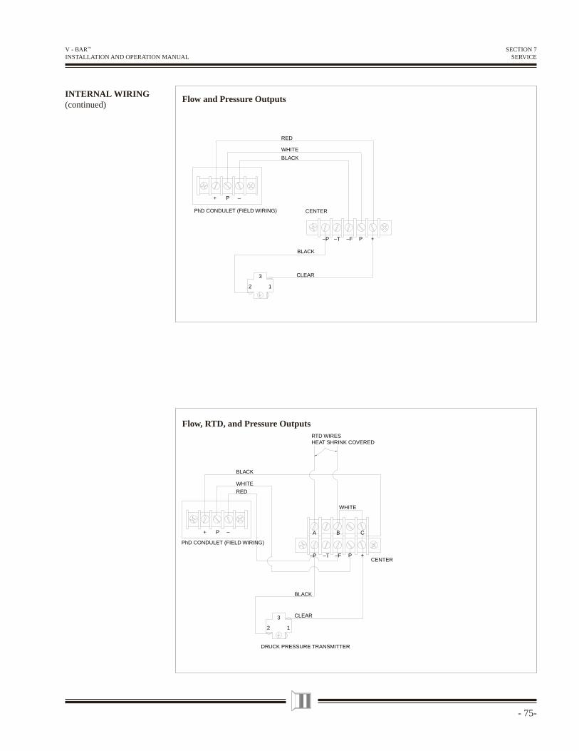
- 75-
V - BAR™ INSTALLATION AND OPERATION MANUAL
SECTION 7SERVICE
WHITE
WHITE
RED
BLACK
1
3
2
–P P +–F
A CB
–T
+ P –
BLACK
CLEAR
CENTER
RTD WIRES HEAT SHRINK COVERED
PhD CONDULET (FIELD WIRING)
DRUCK PRESSURE TRANSMITTER
RED
WHITE
BLACK
–P P +
1
3
2
–F–T
BLACK
CLEAR
CENTER PhD CONDULET (FIELD WIRING)
P+ –
Flow, RTD, and Pressure Outputs
INTERNAL WIRING(continued)
Flow and Pressure Outputs
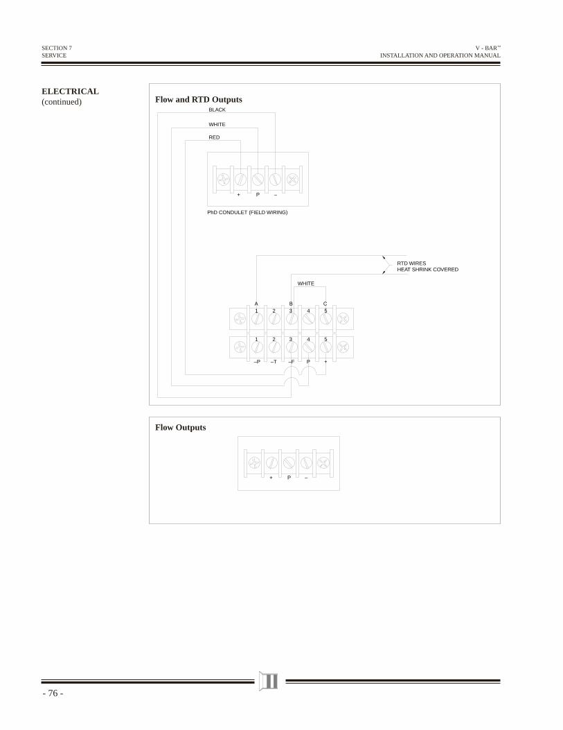
- 76 -
V - BAR™ INSTALLATION AND OPERATION MANUAL
SECTION 7SERVICE
1 2 3 4 5
1 2 3 4 5
RTD WIRES HEAT SHRINK COVERED
PhD CONDULET (FIELD WIRING)
WHITE
WHITE
RED
BLACK
A CB
–P –T –F P +
P+ –
PhD CONDULET (FIELD WIRING)
P+ –
Flow and RTD Outputs
Flow Outputs
ELECTRICAL(continued)
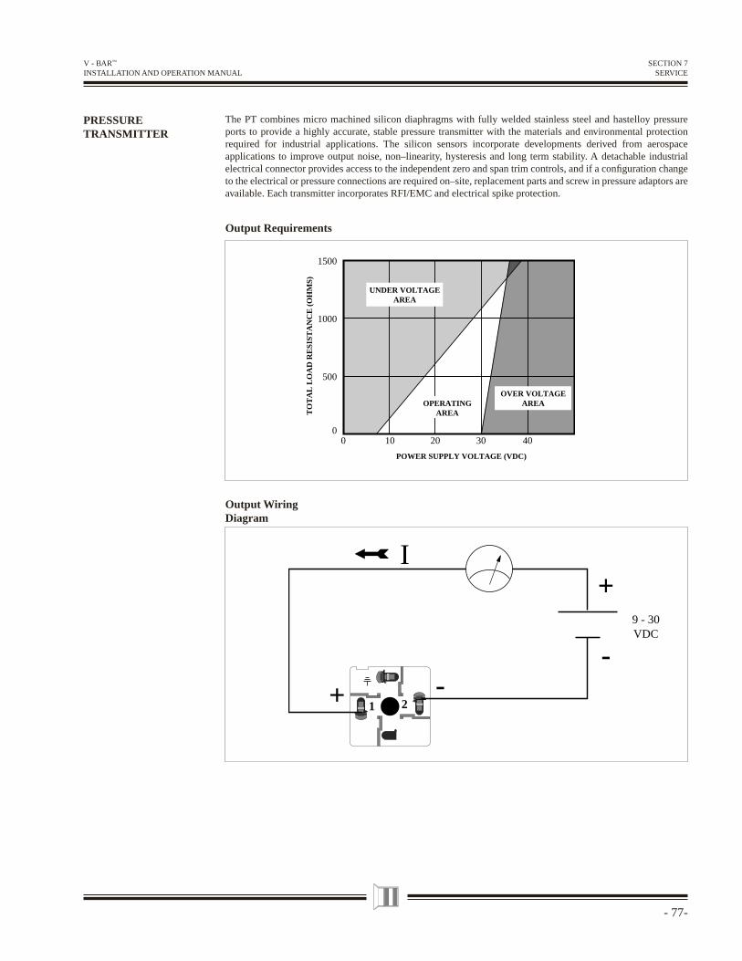
- 77-
V - BAR™ INSTALLATION AND OPERATION MANUAL
SECTION 7SERVICE
PRESSURETRANSMITTER
The PT combines micro machined silicon diaphragms with fully welded stainless steel and hastelloy pressure ports to provide a highly accurate, stable pressure transmitter with the materials and environmental protection required for industrial applications. The silicon sensors incorporate developments derived from aerospace applications to improve output noise, non–linearity, hysteresis and long term stability. A detachable industrial electrical connector provides access to the independent zero and span trim controls, and if a confi guration change to the electrical or pressure connections are required on–site, replacement parts and screw in pressure adaptors are available. Each transmitter incorporates RFI/EMC and electrical spike protection.
Output Requirements
00
TO
TA
L L
OA
D R
ESI
STA
NC
E (
OH
MS)
POWER SUPPLY VOLTAGE (VDC)
500
1000
1500
10 403020
UNDER VOLTAGEAREA
OVER VOLTAGEAREAOPERATING
AREA
Output WiringDiagram
1 2
+
-
I
9 - 30VDC
+ -
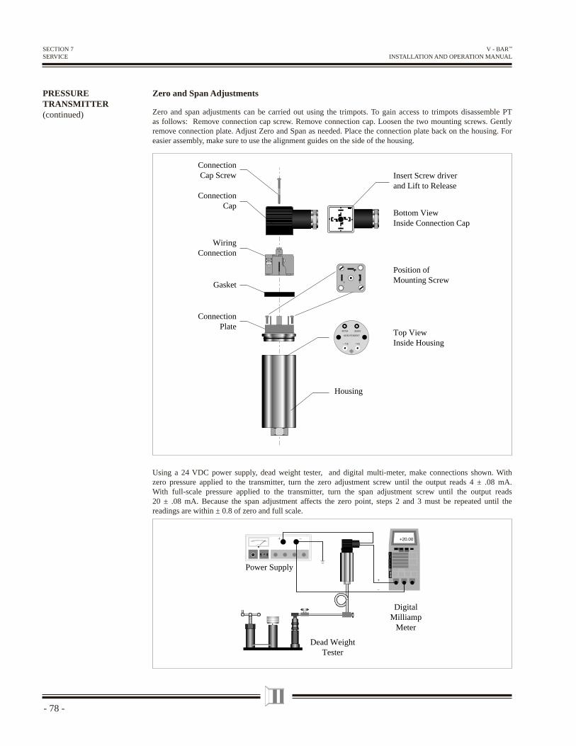
- 78 -
V - BAR™ INSTALLATION AND OPERATION MANUAL
SECTION 7SERVICE
PRESSURETRANSMITTER(continued)
Zero and Span Adjustments
Zero and span adjustments can be carried out using the trimpots. To gain access to trimpots disassemble PT as follows: Remove connection cap screw. Remove connection cap. Loosen the two mounting screws. Gently remove connection plate. Adjust Zero and Span as needed. Place the connection plate back on the housing. For easier assembly, make sure to use the alignment guides on the side of the housing.
Using a 24 VDC power supply, dead weight tester, and digital multi-meter, make connections shown. With zero pressure applied to the transmitter, turn the zero adjustment screw until the output reads 4 ± .08 mA. With full-scale pressure applied to the transmitter, turn the span adjustment screw until the output reads 20 ± .08 mA. Because the span adjustment affects the zero point, steps 2 and 3 must be repeated until the readings are within ± 0.8 of zero and full scale.
+20.00
Power Supply
DigitalMilliamp
Meter
Dead WeightTester
SPAN ZERO
ADJUSTMENT
—VE +VE
Top ViewInside Housing
Position ofMounting Screw1 2
Insert Screw driverand Lift to Release
Bottom ViewInside Connection Cap
ConnectionCap
WiringConnection
ConnectionCap Screw
Housing
Gasket
ConnectionPlate
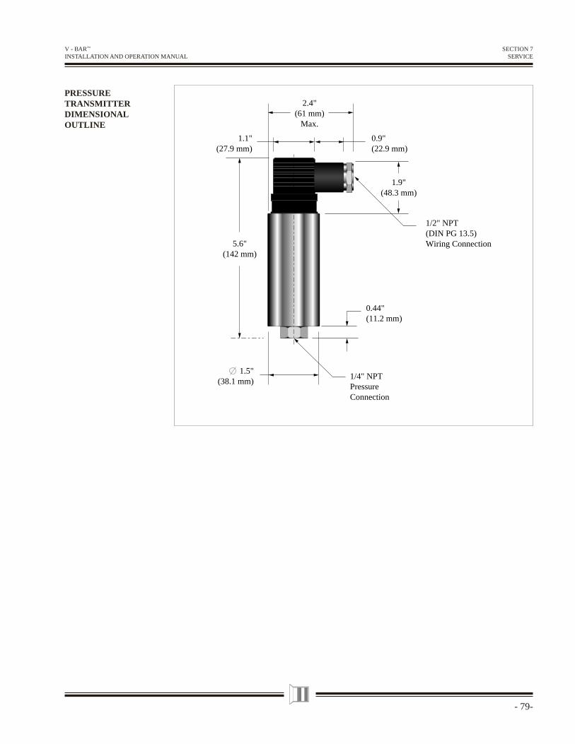
- 79-
V - BAR™ INSTALLATION AND OPERATION MANUAL
PRESSURETRANSMITTERDIMENSIONALOUTLINE
5.6"(142 mm)
1.1"(27.9 mm)
0.9"(22.9 mm)
0.44"(11.2 mm)
1.5"(38.1 mm)
2.4"(61 mm)
Max.
1/4" NPTPressureConnection
1/2" NPT(DIN PG 13.5)Wiring Connection
1.9"(48.3 mm)
SECTION 7SERVICE
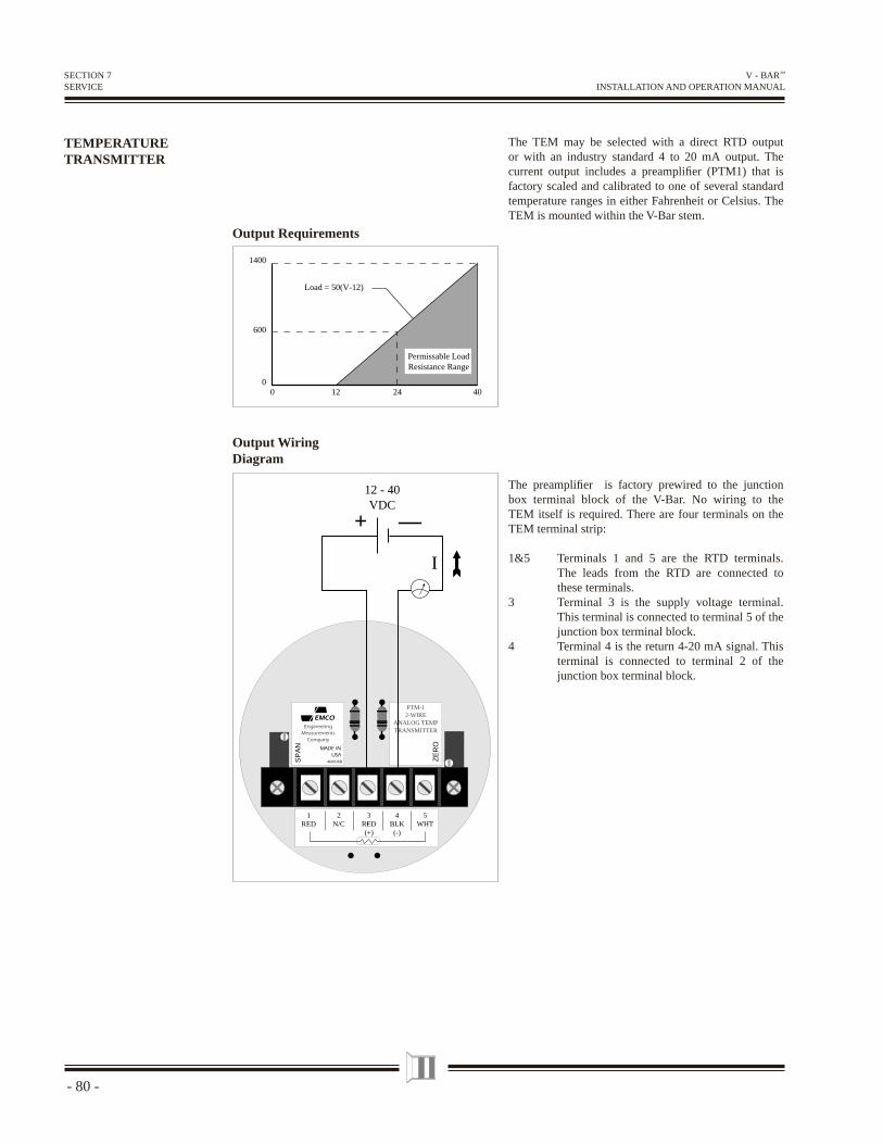
- 80 -
V - BAR™ INSTALLATION AND OPERATION MANUAL
TEMPERATURETRANSMITTER
The TEM may be selected with a direct RTD output or with an industry standard 4 to 20 mA output. The current output includes a preamplifi er (PTM1) that is factory scaled and calibrated to one of several standard temperature ranges in either Fahrenheit or Celsius. The TEM is mounted within the V-Bar stem.
SECTION 7SERVICE
Output Requirements
12 24 4000
600
1400
Permissable LoadResistance Range
Load = 50(V-12)
The preamplifi er is factory prewired to the junction box terminal block of the V-Bar. No wiring to the TEM itself is required. There are four terminals on the TEM terminal strip:
1&5 Terminals 1 and 5 are the RTD terminals. The leads from the RTD are connected to these terminals.
3 Terminal 3 is the supply voltage terminal. This terminal is connected to terminal 5 of the junction box terminal block.
4 Terminal 4 is the return 4-20 mA signal. This terminal is connected to terminal 2 of the junction box terminal block.
I
3RED(+)
2N/C
1RED
4BLK
(-)
5WHT
PTM-12-WIRE
ANALOG TEMPTRANSMITTER
SP
AN
ZE
RO
EMCOEngineering
MeasurementsCompany
MADE INUSA
460036B
+ —
12 - 40VDC
Output WiringDiagram
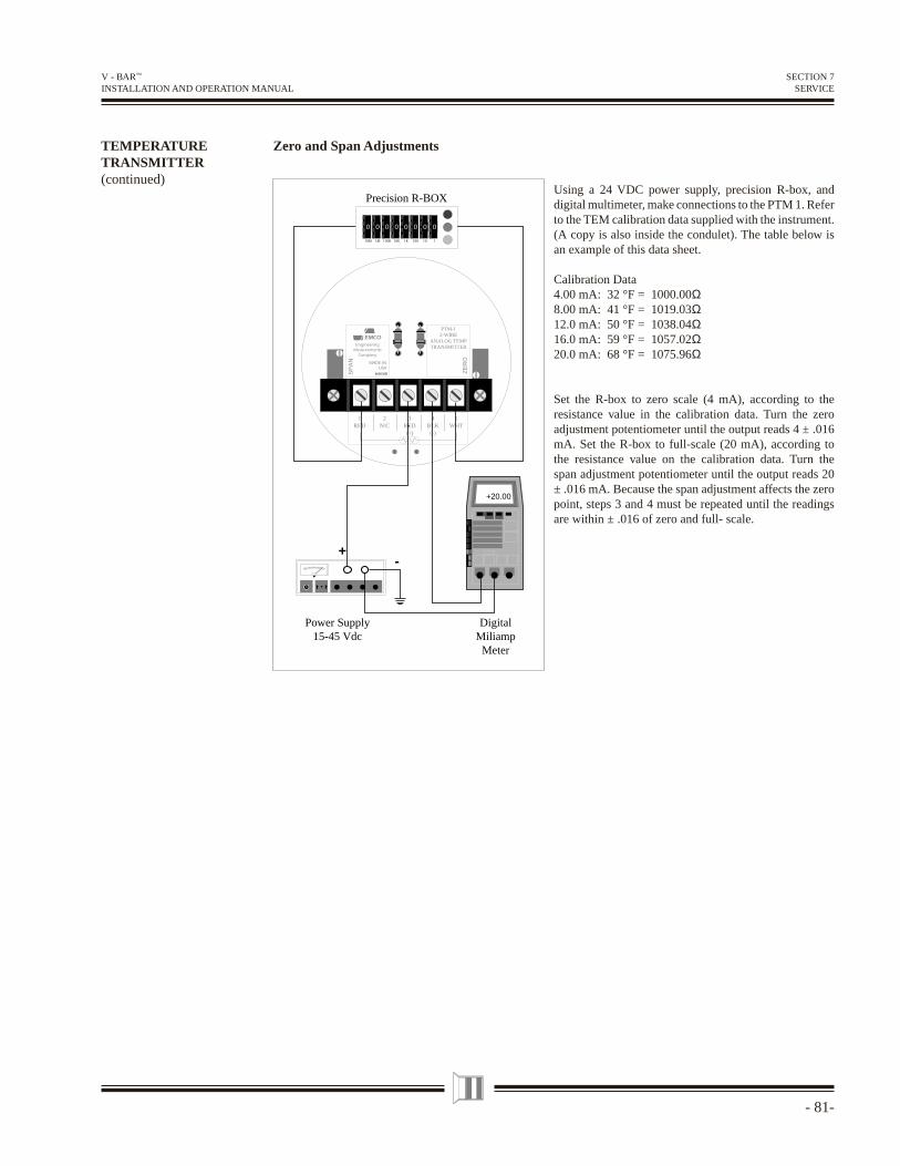
- 81-
V - BAR™ INSTALLATION AND OPERATION MANUAL
SECTION 7SERVICE
TEMPERATURETRANSMITTER(continued)
Using a 24 VDC power supply, precision R-box, and digital multimeter, make connections to the PTM 1. Refer to the TEM calibration data supplied with the instrument. (A copy is also inside the condulet). The table below is an example of this data sheet.
Calibration Data4.00 mA: 32 °F = 1000.00Ω8.00 mA: 41 °F = 1019.03Ω12.0 mA: 50 °F = 1038.04Ω16.0 mA: 59 °F = 1057.02Ω20.0 mA: 68 °F = 1075.96Ω
Set the R-box to zero scale (4 mA), according to the resistance value in the calibration data. Turn the zero adjustment potentiometer until the output reads 4 ± .016 mA. Set the R-box to full-scale (20 mA), according to the resistance value on the calibration data. Turn the span adjustment potentiometer until the output reads 20 ± .016 mA. Because the span adjustment affects the zero point, steps 3 and 4 must be repeated until the readings are within ± .016 of zero and full- scale.
3RED(+)
2N/C
1RED
4BLK
(-)
5WHT
PTM-12-WIRE
ANALOG TEMPTRANSMITTER
SP
AN
ZE
RO
EMCOEngineering
MeasurementsCompany
MADE INUSA
460036B
+20.00
+
Power Supply15-45 Vdc
DigitalMiliamp
Meter
-
0 0 0 0 0 0 0 0
1101001K10K100K1M10M
Precision R-BOX
Zero and Span Adjustments
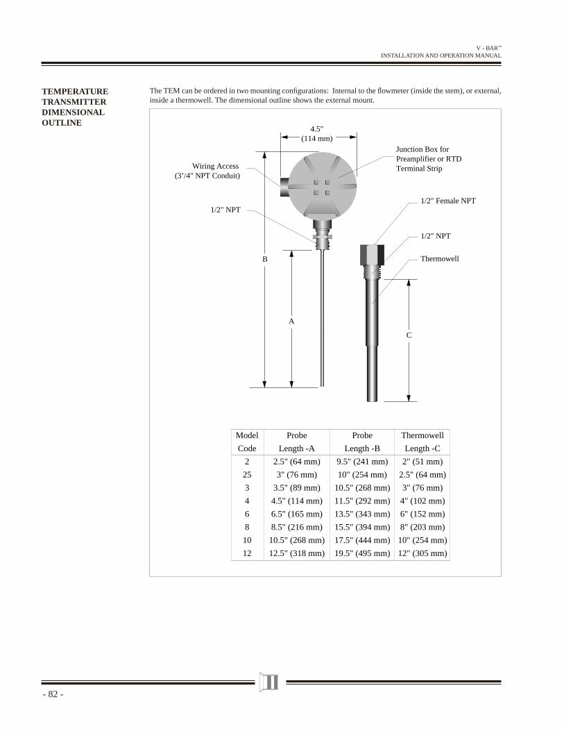
- 82 -
V - BAR™ INSTALLATION AND OPERATION MANUAL
The TEM can be ordered in two mounting confi gurations: Internal to the fl owmeter (inside the stem), or external, inside a thermowell. The dimensional outline shows the external mount.
TEMPERATURETRANSMITTERDIMENSIONALOUTLINE
C
4.5"(114 mm)
A
B
1/2" NPT
1/2" NPT
1/2" Female NPT
Thermowell
Wiring Access(3’/4" NPT Conduit)
Junction Box forPreamplifier or RTDTerminal Strip
Model
Code
2
25
3
4
6
8
10
12
Probe
Length -A
2.5" (64 mm)
3" (76 mm)
3.5" (89 mm)
4.5" (114 mm)
6.5" (165 mm)
8.5" (216 mm)
10.5" (268 mm)
12.5" (318 mm)
Probe
Length -B
9.5" (241 mm)
10" (254 mm)
10.5" (268 mm)
11.5" (292 mm)
13.5" (343 mm)
15.5" (394 mm)
17.5" (444 mm)
19.5" (495 mm)
Thermowell
Length -C
2" (51 mm)
2.5" (64 mm)
3" (76 mm)
4" (102 mm)
6" (152 mm)
8" (203 mm)
10" (254 mm)
12" (305 mm)
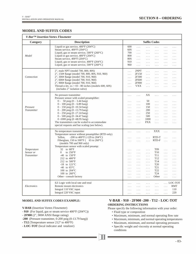
- 83-
V - BAR™ INSTALLATION AND OPERATION MANUAL SECTION 8 – ORDERING
V-Bar™ Insertion Vortex Flowmeter
Category Description Suffi x Codes
Liquid or gas service, 400°F (204°C) 600 . . . . . . . . . . . . . . . Steam service, 400°F (204°C) 60S . . . . . . . . . . . . . . . Liquid, gas or steam service, 500°F (260°C) 700 . . . . . . . . . . . . . . .
Model Liquid or gas service, 400°F (204°C) 800 . . . . . . . . . . . . . . . Steam service, 400°F (204°C) 80S . . . . . . . . . . . . . . . Liquid, gas or steam service, 400°F (204°C) 910 . . . . . . . . . . . . . . . Liquid, gas or steam service, 500°F (260°C) 960 . . . . . . . . . . . . . . .
2", male NPT (model 700, 800, 80S) . . . 2NPT . . . . . . . . . . . . 2", 150# fl ange (model 700, 800, 80S, 910, 960) . . . 2F150 . . . . . . . . . . . .
Connection 2", 300# fl ange (model 700, 910, 960) . . . 2F300 . . . . . . . . . . . . 2", 600# fl ange (model 700, 910, 960) . . . 2F600 . . . . . . . . . . . . 2", 900# fl ange (model 700, 910, 960) . . . 2F900 . . . . . . . . . . . . Thread-o-let, xx = 03 - 80 inches (models 600, 60S) . . . VXX . . . . . . . . . . . . (includes 2" isolation valve)
No pressure transmitter . . . . . . XX . . . . . . . . . Pressure sensor with scaled preamplifi er: 0 - 50 psig (0 - 3.44 barg) . . . . . . 50 . . . . . . . . . 0 - 100 psig (0 - 6.89 barg) . . . . . . 100 . . . . . . . . .Pressure 0 - 150 psig (0 -10.34 barg) . . . . . . 150 . . . . . . . . .Transmitter 0 - 200 psig (0 -13.79 barg) . . . . . . 200 . . . . . . . . . 0 - 250 psig (0 -17.24 barg) . . . . . . 250 . . . . . . . . . 0 - 500 psig (0 -34.47 barg) . . . . . . 500 . . . . . . . . . 0 -1000 psig (0 -68.95 barg) . . . . . . 1000 . . . . . . . . . The transmitters can be scaled to accommodate . . . . . . PXX . . . . . . . . . special requests and bar scaling (see below). No temperature transmitter . . . . . . . . . XXX . . . . . . Temperature sensor without preamplifi er (RTD only) Tefl on, -200 to 400°F (-129 to 204°C) . . . . . . . . . RTD-T . . . . . . Fiberglass, 150 to 500°F ( 65 to 260°C) . . . . . . . . . RTD-F . . . . . . (models 700 and 960 only) Temperature sensor with scaled preamp:
Temperature 32 to 68°F . . . . . . . . . T09 . . . . . .Sensor or 0 to 250°F . . . . . . . . . T10 . . . . . .Transmitter -40 to 150°F . . . . . . . . . T11 . . . . . . 212 to 400°F . . . . . . . . . T12 . . . . . . 212 to 500°F . . . . . . . . . T14 . . . . . . -18 to 121°C . . . . . . . . . T20 . . . . . . -40 to 65°C . . . . . . . . . T21 . . . . . . 100 to 204°C . . . . . . . . . T22 . . . . . . 100 to 260°C . . . . . . . . . T24 . . . . . . Other - consult factory . . . . . . . . . Other . . . . . .
EZ Logic with local rate and total . . . . . . . . . . . . . . . LOC-TOTElectronics Remote mount electronics . . . . . . . . . . . . . . . RMT Integral 110 VAC input . . . . . . . . . . . . . . . 110 Integral 220 VAC input . . . . . . . . . . . . . . . 220
MODEL AND SUFFIX CODES
ORDERING INSTRUCTIONSPlease specify the following information with your order: • Fluid type or composition • Maximum, minimum, and normal operating fl ow rate • Maximum, minimum, and normal operating temperatures • Maximum, minimum, and normal operating pressures • Specifi c weight and viscosity at normal operating conditions
MODEL AND SUFFIX CODES EXAMPLE: V-BAR - 910 - 2F900 -200 - T12 - LOC-TOT
V-BAR (Insertion Vortex Flowmeter)- 910 (For liquid, gas or steam service 400°F (204°C))- 2F900 (2", 900# ANSI fl ange rating) -200 (Pressure transmitter, 0-200 psig (0-13.79 barg))- T12 (Temperature sensor 212° to 400°F)- LOC-TOT (local indicator and totalizer)


Providing innovative fl owmeter products and services for over three decades . . .Engineering Measurements Company (EMCO) is a long established manufacturer of precision fl owmeters for liquid, gas, and steam appli-cations for commerce and industry. Manufactured under an ISO 9001 certifi ed quality system, which includes extensive fl ow calibra-tion capability, engineering, applications, and service, underpining a world-wide sales and service organization totally focused on provid-ing the best fl owmeters and customer service in the industry.
4 Manufacturing is housed in a modern plant located in
Longmont, Colorado
4 Modern clean-room, mechanized assembly equipment,
and computer based testing ensure the highest quality product
4 Trained professional fl ow specialists and technicians offer
timely customer assistance
4 Factory trained and certifi ed fi eld technicians provide product
support services
Engineering Measurements Company600 Diagonal Hwy. • Longmont, CO 80501 • (303) 651-0550 • Fax (303) 678-7152 • sales@emcofl ow.com
MAGFLO® Electromagnetic
V-Bar™ InsertionVortex
Turbo-Bar™
InsertionTurbine
Vortex PhD™ Inline Vortex
PDH Helix PDP Piston
Sono-Trak™
990333 Rev. ESpecifi cations subject to change without notice.