Embed Size (px)
Citation preview

DIRECT EXPANSION SYSTEMS
passport I/O controlsOperation Manual
Revised: 9-18-07 L-2231

3 ❖ English L-2231
Table of Contents
Copyright 2007 Dometic Environmental Corporation., All Rights Reserved - Every precaution has been taken in the preparation of this manual to insure its accuracy. However, Dometic Environ-mental Corporation assumes no responsibility for errors or omissions. Neither is any liability assumed for damages resulting from the use of this product and information contained herein.
Passport I/O Controls • Introduction 4Standard Features .......................................................................................................................................4Optional Features ........................................................................................................................................4Overview .....................................................................................................................................................4Normal Heating or Cooling Cycle ................................................................................................................5Reversing Valve Operation ..........................................................................................................................5
Passport I/O Controls • Installation 6Display Panel Installation ............................................................................................................................6
Passport I/O Controls • Basic Operation 7Operator Controls and Display Panel ..........................................................................................................7Dual Button Functions .................................................................................................................................7Special Button Functions .............................................................................................................................8Modes of Operation .....................................................................................................................................8Program Mode .............................................................................................................................................8Entering Program Mode ..............................................................................................................................8Restore Memorized Default Settings .............................................................................................................9Using the Program Mode ............................................................................................................................9Programming ...............................................................................................................................................9Failsafe and Fault Handling Codes ............................................................................................................12Quick Start Operations Checklist ..............................................................................................................13
Passport I/O Controls • Troubleshooting 14General Troubleshooting ..........................................................................................................................14Digital Controls Troubleshooting ...............................................................................................................15
Passport I/O Controls • Maintenance 18Reversing Valves .......................................................................................................................................18Seawater Strainer ......................................................................................................................................18Condenser Coil Cleaning ..........................................................................................................................18Return Air Filters .......................................................................................................................................18Winterization .............................................................................................................................................18
Passport I/O Controls • Specifications 19Dimensions ................................................................................................................................................19Cable Lengths ...........................................................................................................................................19System Inputs ............................................................................................................................................19Automated Factory Self Test Program .......................................................................................................20Service Tools .............................................................................................................................................20Sample Wiring Diagram.............................................................................................................................21
Passport I/O Controls • Manufacturers Limited Warranty Agreement 22
Marine Air Vector Turbo • Manufacturer’s Limited Warranty 23
Marine Air Worldwide Service Dealer Locator 24
L-2231 Introduction 4 ❖ English
Passport I/O Controls • Introduction
Passport I/O is a micro controller based unit designed for use with direct expansion, reverse cycle air conditioning systems.
Standard Features•Universal 115/230 volt, 50/60 Hz AC power supply.
•User friendly four button display panel.
•Five volt micro controller located in the display.
•Displays degrees Fahrenheit or degrees Celsius.
•Face plate ambient air sensor.
•20 programmable parameters.
•High/Low Freon pressure switch inputs.
•Humidity Mode control.
•De-icing cycle prevents evaporator icing.
•Programmable fan operation.
•Programmable compressor delays.
•Nonvolatile memory requiring no backup power.
•Programmable display brightness.
•Programmable fail-safe modes.
Optional Features•Electric heating control capabilities
•Outside air temperature sensor.
•Alternate air temperature sensor.
This manual provides all necessary information for proper installation and operation of Passport I/O. Poor installation or misunderstood operating parameters will result in unsatisfactory performance and possible failure.
Read This Manual Completely Before Proceeding !If you have questions, or require assistance with your Passport I/O control, contact Dometic Environmental Corporation (Dometic).
The Passport I/O is covered under existing Marine Air Warranty Policy. Incorrect installation, neglect and system abuse are not covered under Marine Air Warranty Policy.
OverviewPress the Power Button once to engage the system. The display indicates room temperature when the system is on and is blank when the system is off.
Set the desired room temperature by pressing the Up or Down Button. The set point can be viewed by momentarily pressing and releasing the Up or Down Button.
Fan speed operation is automatic allowing fan speed to decrease as room temperature is approached in the Cool Mode. The fan will operate at low speed when set point is satisfied. Manual fan speeds can be selected with the Fan Button.
The fan can be programmed to run only when cooling or heating is required. Normally the automatic fan speed op-eration is reversed in the Heating Mode, however, the fan can be programmed to operate the same as in the Cooling Mode.
Memory: Passport I/O has nonvolatile memory requir-ing no batteries or backup power. When power is lost the operating parameters are retained indefinitely. When power is restored, the control resumes operating as last pro-grammed.
Important Programming Notes To Installer and End User:1. If your air conditioning unit is a 24,000 BTU model, or if
it has a High Velocity blower, then you MUST reprogram parameter P-16 prior to operating equipment. A 24K unit is identifiable by the “24” in the model number (i.e., VCD24K). A High Velocity blower does not have a blower motor overhang, the motor is inside the blower, and there is an “HV” in the model number. See the Program-ming section P-16 for instructions.
2. If your air conditioning unit is Cool Only - if it does not have a reversing valve - then Cool Only Mode MUST be programmed into parameter P-1 (factory default is Automatic Mode). DO NOT program Automatic Mode for a Cool Only unit. If Automatic Mode is selected and the thermostat calls for heat, the compressor will run. Since there is no reversing valve, the air conditioning unit will supply cool air when heating is desired. Cool Only units do not heat. Please see programmable parameter P-1 for more information on how to set the proper operating mode.
L-2231 Introduction 5 ❖ English
3. When powering on the Passport I/O control, press and immediately release the Power button so as to not unin-tentionally enter Program Mode. Program Mode will be entered if the Power button is pressed and held for more than 5 seconds. If Program Mode is entered unintention-ally, any subsequent presses of the Up or Down buttons will change the P-1 parameter setting since it is the first parameter shown after entering this mode. This will in turn change the operating mode to Cool Only, Heat Only, or Automatic, which could result in improper system operation. Please use care when using Program Mode and refer to the corresponding sections in this manual for further information.
Normal Heating or Cooling CycleAutomatic heating and cooling will be supplied as required. Automatic operation maintains a 2°F (1.1°C) temperature variation. A 4°F (2.2°C) change in temperature is required to cause the unit to shift to the opposite mode. Once in Heating or Cooling Mode, Passport I/O will maintain a 2°F (1.1°C) differential.
Program Cool only and cooling only will be supplied. The cabin temperature will be maintained within 2°F (1.1°C) of set point. Program Heat only and heating only will be sup-plied. The cabin temperature will be maintained within 2°F (1.1°C) of set point.
When the heating or cooling is satisfied, the compres-sor cycles off and the fan returns to low speed. The fan speed will remain constant if Manual Fan Speed has been selected.
Reversing Valve OperationThe reversing valve is toggled to the opposite mode when heating or cooling is required to reduce the compressor starting surge. The valve will only toggle to the opposite mode when a cooling or heating cycle is called for and if the system has been off for less than 75 seconds. The valve will also toggle if a cycle is interrupted from the dis-play panel by pressing the Power Button, or changing the set point. Unnecessary valve toggling has been limited to reduce reversing valve noise. Valve toggling can be totally eliminated by programming the minimum compressor stag-ing delay at 75 seconds or greater (program P-4).
Power On Reset, which occurs when the system is pow-ered up, will always initiate a valve toggle.
L-2231 Installation 6 ❖ English
Display Panel InstallationBefore mounting the Passport I/O or AH-Passport I/O digital display panel touch pad, consider the location. The air sensor built into the display panel will provide excellent room air temperature sensing given a proper installation. The display panel should be mounted on an inside wall, slightly higher than mid-height of the cabin, in a location with freely circulating air where it can best sense aver-age temperature. The cut out size for the display panel is 3.375" (86mm) wide by 2.875" (73mm) high.
Do not mount the display in direct sunlight, near any heat producing appliances or in a bulkhead where temperatures radiating from behind the panel may affect performance. Do not mount the display in the supply air stream. Do not mount the display above or below a supply or return air grille. Do not mount the display behind a door, in a corner, under a stairwell or any place where there is no freely circulating air.
Mount the display within display cable length (custom lengths available) of the air conditioner. Plug one end of the display cable (8-pin connector) into the upper right-hand socket on the circuit board in the electric box and the other end into the back of the display panel. Secure the display panel to a bulkhead with the adhesive strips pro-vided. Clean the mounting surface with isopropyl alcohol only prior to placement (test alcohol on hidden portion of surface first). If the adhesive strips cannot be used directly on the bulkhead then use the plastic bulkhead adapter. The bulkhead adapter (sold separately) is mounted to the bulk-head with screws and the display panel is secured to the adapter with adhesive strips. Do not use a screw gun and do not over-tighten screws when mounting adapter.
Passport I/O Controls • Installation
If a proper location for room temperature sensing cannot be found for the display, an optional remote air sensor may be used. Mount the remote air sensor in the return air stream behind the return air grille/ opening and plug its cable (7'/2.1m standard length with 6-pin connector) into the “ALT AIR” socket #J4 in the upper left-hand corner of the circuit board. Installing the remote air sensor will over-ride the faceplate sensor. An optional outside air tempera-ture sensor and cable may also be used. Plug that cable into the “OAT” socket #J3 (next to #J4). Mount the sensor outside but not in direct sunlight. Air sensor cables are available in various lengths. Do not staple any cables when mounting.
When using the AH-Passport I/O with a chilled water air handler, plug the water inlet sensor cable into the “SERVICE/H2O” socket #J5.
L-2231 Operation 7 ❖ English
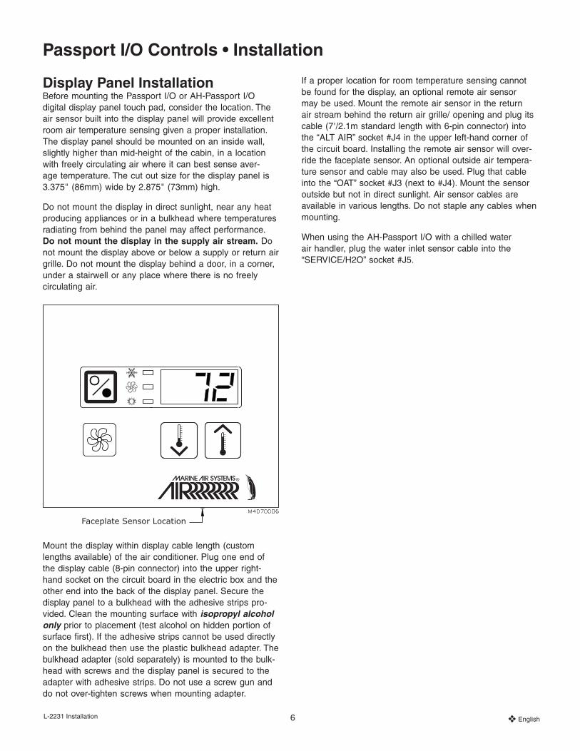
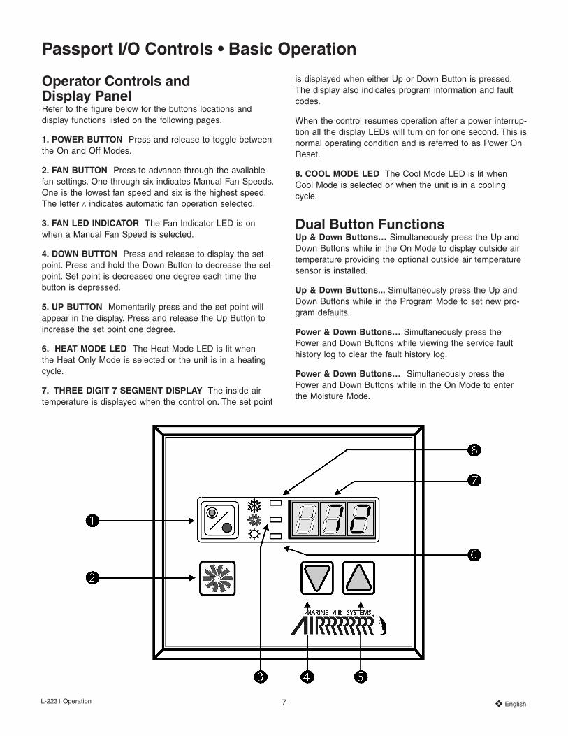
Operator Controls and Display PanelRefer to the figure below for the buttons locations and display functions listed on the following pages.
1. POWER BUTTON Press and release to toggle between the On and Off Modes.
2. FAN BUTTON Press to advance through the available fan settings. One through six indicates Manual Fan Speeds. One is the lowest fan speed and six is the highest speed. The letter a indicates automatic fan operation selected.
3. FAN LED INDICATOR The Fan Indicator LED is on when a Manual Fan Speed is selected.
4. DOWN BUTTON Press and release to display the set point. Press and hold the Down Button to decrease the set point. Set point is decreased one degree each time the button is depressed.
5. UP BUTTON Momentarily press and the set point will appear in the display. Press and release the Up Button to increase the set point one degree.
6. HEAT MODE LED The Heat Mode LED is lit when the Heat Only Mode is selected or the unit is in a heating cycle.
7. THREE DIGIT 7 SEGMENT DISPLAY The inside air temperature is displayed when the control on. The set point
is displayed when either Up or Down Button is pressed. The display also indicates program information and fault codes.
When the control resumes operation after a power interrup-tion all the display LEDs will turn on for one second. This is normal operating condition and is referred to as Power On Reset.
8. COOL MODE LED The Cool Mode LED is lit when Cool Mode is selected or when the unit is in a cooling cycle.
Dual Button FunctionsUp & Down Buttons… Simultaneously press the Up and Down Buttons while in the On Mode to display outside air temperature providing the optional outside air temperature sensor is installed.
Up & Down Buttons... Simultaneously press the Up and Down Buttons while in the Program Mode to set new pro-gram defaults.
Power & Down Buttons… Simultaneously press the Power and Down Buttons while viewing the service fault history log to clear the fault history log.
Power & Down Buttons… Simultaneously press the Power and Down Buttons while in the On Mode to enter the Moisture Mode.
Passport I/O Controls • Basic Operation
L-2231 Operation 8 ❖ English
Special Button FunctionsSpecial button functions are implemented by pressing and holding a particular button while the controls’ AC power is turned on.
1. Service History Log… View the service history log by pressing and holding the Fan Button while turning on the AC power. Exit the service history log by pressing the Power Button once. See the Service History Log section.
2. Self Test Mode… Press and hold the Power Button while AC power is applied to enter the Self Test Mode. The self test is used to diagnose problems and test the air con-ditioning system. For complete details see the Automated Factory Self Test Program section.
3. View Hour Meter… To view the compressor hour meter, press and hold the Down Button while applying AC power. Maximum recorded time is 65,536 hours. The hour meter functions are described fully in the Service Tools section.
Modes of OperationOff ModeWhen the Passport I/O is in the Off Mode, all control out-puts are turned off. Program parameters and user settings are saved in nonvolatile memory. The Program Mode can only be accessed from the Off Mode.
On ModeWhen the control is in the On Mode power is supplied to the appropriate outputs and the display indicates the cur-rent state of operation. The operating and program param-eters resume based on those stored the last time the unit was operating.
Cooling ModeWhen Cool Mode is selected the cooling systems are oper-ated as required. When the temperature drops below the set point, the system will not automatically switch to the Heat Mode.
Heat ModeWhen the Heat LED is on, only the heating systems are selected and operated as required. Should the temperature rise above the set point, the system will not automatically switch to the Cool Mode.
Automatic ModeAutomatic Mode provides both heating and cooling as required. The Heat or Cool LED will be lit according to the mode required. Temperature in a given mode is maintained within 2°F (1.1°C) of set point, however a 4°F (2.2°C) dif-ference is required to allow the control to change modes. Once the mode changes temperature will be maintained within 2°F (1.1°C) of set point.
Manual Fan ModePress and hold the Fan Button during normal operation to select one of the six manual fan speeds available. The fast-est fan speed is represented by “6”, the slowest represent-ed by “1”. Manual Fan Mode allows the user to select the desired fan speed manually. When a manual fan speed has been selected, the fan LED will be lit. Manual Fan Mode is sometimes preferred when room temperature is constantly changing due to varying heat loads.
Circulation ModeWhen the system is off at the display panel the fan can be used to only circulate the air. Press and hold the Fan But-ton when the display is off until the desired speed number appears in the window. Release the Fan Button and the fan will run at the selected speed circulating the air without heating or cooling. Press the Power Button once to cancel the Circulation Mode and enter the On Mode.
Moisture ModeWhile in the On Mode simultaneously press the Power and Down Buttons. The first cycle will start in one minute. Every four hours, the fan is started and air circulated for thirty minutes. During this time the air temperature is sampled and entered into memory. The cooling cycle is started and continues until the temperature is lowered 2°F (1.1°C). The compressor is allowed a maximum of one hour running time to reach the desired temperature. Four hours after the temperature is satisfied or the compressor times out, the cycle is repeated. The “HU1” mnemonic code is displayed while in the Moisture Mode.
Press the Power Button to end the Moisture Mode.
Program ModeThe Program Mode is used to adjust the systems operating parameters to suit the particular needs of individual users. The Program Mode is also used to tailor the air condi-tioning system for the most efficient operation within an installation. Variables such as, ducting, sensor location and system layout affect the system operation. Passport I/O is shipped with factory default settings which are stored in permanent memory and can be recalled at any time.
Entering Program ModeThe program mode can only be entered from the Off Mode. Press and hold the Power Button while in the Off Mode un-til the letter “P” appears in the display. The characters “P1” followed by the parameter setting, appear in the display. The Passport I/O control is now in the Program Mode.
NOTE: The control will exit the Program Mode and return to the Off Mode if no programming is attempted for one minute.
L-2231 Operation 9 ❖ English
Restore Memorized Default SettingsIMPORTANT ! The memorized default settings can be restored by entering the Program Mode and setting P-17 to “rSt”. Exit the Program Mode and the software version number (“A12”) appears in the display. The memorized default settings are restored and the Passport I/O control returns to the Off Mode.
Using the Program ModeIncrement from one program parameter to the next by pressing the Fan Button while in the Program Mode. Press and release the Fan Button to advance to the desired parameter. The programmable parameters range from P-1 through P-22.
Up and Down ButtonsThe Up and Down Buttons are used to select the data or set the desired limits for the parameter being pro-grammed.
Saving New Program Parameters Simultaneously press the Up and Down Buttons while in the Program Mode to save the new program parameters. This will also set the new program defaults. Factory de-faults shown in the table may be reset manually.
Exiting the Program ModeThere are two methods to exit the Program Mode. Press the Power Button and the control will return to the Off Mode. Not pressing any buttons or attempting any program changes for one minute will exit the Program Mode.
Software IdentificationThe software version of the control is identified for one second prior to the exit from the Program Mode. The soft-ware identification number, i.e. (“A12”) will appear in the display for one second, then the control will return to the Off Mode.
NOTE:Should there be any reason to contact Dometic about the system or programming Passport I/O be sure to have the software identification number and air condi-tioning unit serial number available. The serial number may be found on the dataplate label.
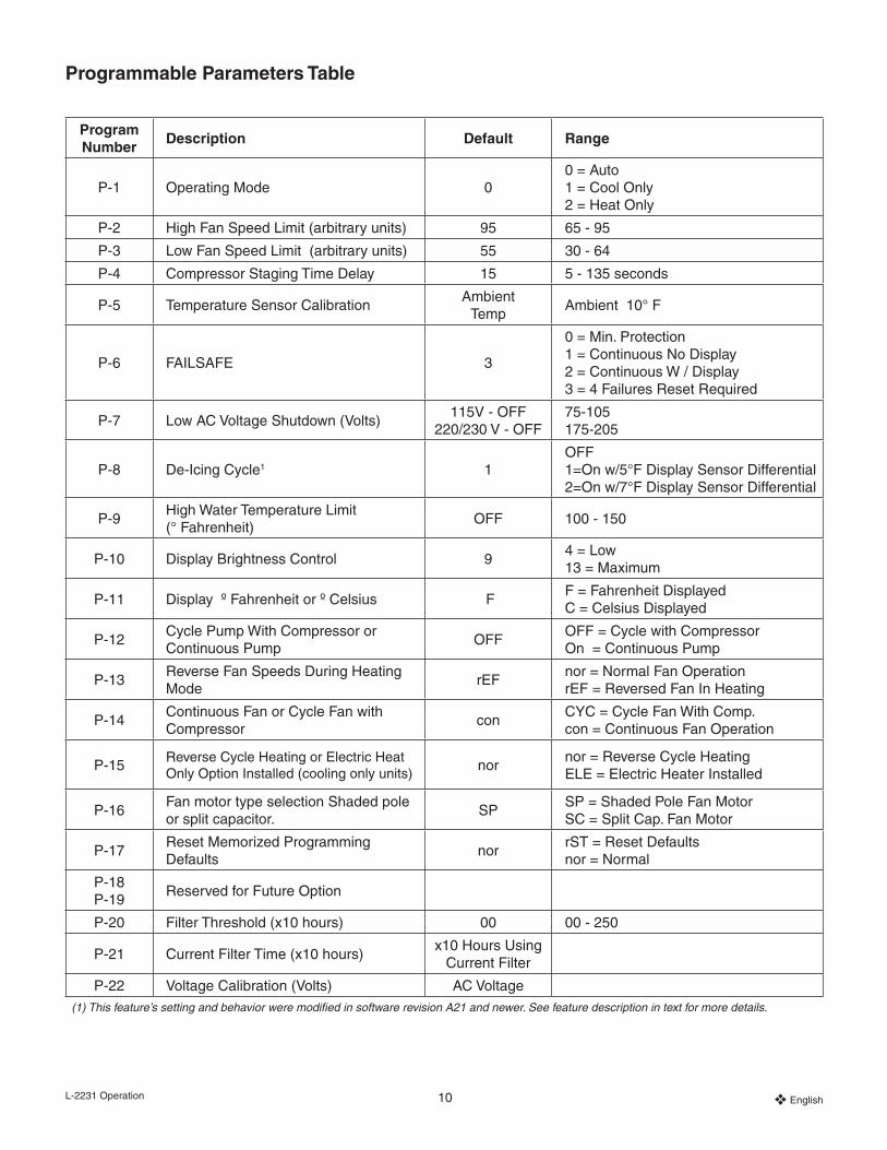
ProgrammingProgrammable ParametersThere are 20 programmable parameters with their factory default settings listed in this section. The following table indicates what these parameters are, along with the permit-ted values and the original factory default settings.
Should any programming problems or confusion occur, reset the Memorized Default Settings by entering the program mode and setting P-17 to “rSt”.
P-1: Operating ModeThe following operating modes can be selected: Automatic Mode by programming “0”, Cool Mode by selecting “1” and Heat Mode by selecting “2”.
P-2: High Fan LimitThe upper fan speed limit can be adjusted for various mo-tors. The high fan limit is adjusted with the system installed and operating. The values range from 65 through 95 arbitrary units. Set a higher number for a higher fan speed. Set lower number to lower the fan speed. Use the Up and Down Buttons to select the desired speed.
P-3: Low Fan LimitThe low fan limit determines the lowest output allowed for the low fan speed. The values from 30 through 64, arbitrary units. Use the Up and Down Buttons to select the low fan limit. Set a higher number, for higher fan speed. Setting lower numbers lowers the fan speed.
IMPORTANT ! Once the high and low fan speed limits are set, the unit will automatically readjust the remaining speeds to produce three equally spaced fan speeds in both Automatic and Manual Fan Modes.
P-4: Compressor Staging Time DelayThe compressor staging delay is provided for installa-tions where more than one system operates from the same power source. Setting different staging delays allows compressors to start at different times when power is inter-rupted. Units should be staged five seconds apart. The minimum delay is five seconds and the maximum is 135 seconds. (See the Reversing Valve Operation section for programming tips.)
P-5: Temperature CalibrationUse this feature to calibrate the ambient sensor. Select P-5 and the ambient temperature appears in the display. Use the Up and Down Buttons to set the correct reading. The temperature in the display will increase or decrease as required.
L-2231 Operation 10 ❖ English
Programmable Parameters Table
Program Number
Description Default Range
P-1 Operating Mode 00 = Auto 1 = Cool Only 2 = Heat Only
P-2 High Fan Speed Limit (arbitrary units) 95 65 - 95
P-3 Low Fan Speed Limit (arbitrary units) 55 30 - 64
P-4 Compressor Staging Time Delay 15 5 - 135 seconds
P-5 Temperature Sensor CalibrationAmbient
TempAmbient 10° F
P-6 FAILSAFE 3
0 = Min. Protection 1 = Continuous No Display 2 = Continuous W / Display 3 = 4 Failures Reset Required
P-7 Low AC Voltage Shutdown (Volts)115V - OFF
220/230 V - OFF75-105 175-205
P-8 De-Icing Cycle1 1OFF 1=On w/5°F Display Sensor Differential2=On w/7°F Display Sensor Differential
P-9High Water Temperature Limit (° Fahrenheit)
OFF 100 - 150
P-10 Display Brightness Control 94 = Low 13 = Maximum
P-11 Display º Fahrenheit or º Celsius FF = Fahrenheit Displayed C = Celsius Displayed
P-12Cycle Pump With Compressor or Continuous Pump
OFFOFF = Cycle with Compressor On = Continuous Pump
P-13Reverse Fan Speeds During Heating Mode
rEFnor = Normal Fan Operation rEF = Reversed Fan In Heating
P-14Continuous Fan or Cycle Fan with Compressor
conCYC = Cycle Fan With Comp. con = Continuous Fan Operation
P-15Reverse Cycle Heating or Electric Heat Only Option Installed (cooling only units)
nor nor = Reverse Cycle Heating ELE = Electric Heater Installed
P-16Fan motor type selection Shaded pole or split capacitor.
SP SP = Shaded Pole Fan Motor SC = Split Cap. Fan Motor
P-17Reset Memorized Programming Defaults
nor rST = Reset Defaults nor = Normal
P-18 P-19
Reserved for Future Option
P-20 Filter Threshold (x10 hours) 00 00 - 250
P-21 Current Filter Time (x10 hours)x10 Hours Using
Current Filter
P-22 Voltage Calibration (Volts) AC Voltage(1) This feature’s setting and behavior were modified in software revision A21 and newer. See feature description in text for more details.

L-2231 Operation 11 ❖ English
P-6: Fail Safe LevelThere are four fail safe levels. See “Failsafe and Fault Han-dling Codes later in this section.
P-7: Low AC Voltage Shutdown
Use this feature to shut down the unit if the voltage drops to a dangerously low level. By default it is off, but it can be set between 75 and 105 for a 115 Volt unit, and from 175-205 for a 220/230 Volt unit. This feature works immediately at start up, but while running will require a 5 minute delay before displaying a fault to prevent nuisances. The fault code is “LAC”.
P-8: De-Icing CyclePassport I/O is equipped with a de-icing cycle to prevent ice build up on the evaporator coil during extended periods of cool-ing operation. Installation variables such as grille sizes, length of ducting, insulation R factors and ambient temperatures determine the cooling run time required to achieve set point. Customer usage may substantially increase run times by op-erating the system with the hatches and doors open. Program-ming an unrealistic set point (e.g. 65°F/18.3°C) and leaving the salon door open will usually cause the evaporator to ice up on warm humid days.
For Passport I/O software revision A15 and older, de-ic-ing is accomplished by switching the reversing valve into the Heat Mode while the system is cooling. The valve will remain energized for the programmed cycle time. The cycle is programmable to “OFF” or to a period of one, two, or three minutes.
For Passport I/O software revision A21 and newer, de-ic-ing is accomplished using a more sophisticated algorithm that closely monitors the room air temperature in repeating 10-minute intervals during a cooling cycle. Depending on the value and change in room temperature during these monitoring intervals, the Passport I/O will perform various actions to prevent ice from forming and/or melt ice that may have already formed. This is accomplished by short compressor shutdown periods combined with a one-speed increase in fan speed, and by periodic Heat Mode cycles with the fan turned off.
This de-icing feature is turned ON by default with program-ming parameter P-8 set to “1”. The behavior of the feature is always the same whenever an optional alternate air tem-perature sensor is installed . However, the feature has two different, selectable behavior modes when it is used in con-junction with the Passport I/O display’s built-in room air tem-perature sensor. It attempts to compensate for any tempera-ture discrepancy that the display sensor may experience. Although this discrepancy is not typical, installation variables such as where the Elite display is placed inside the room (e.g. near an open door or in direct sunlight) can affect how accurately it can read the actual room temperature.
By default with P-8 set to “1”, the algorithm is applied as-suming the display sensor may be reading the room tem-perature as much as 5°F (2.8°C) greater than the actual evaporator temperature. With programmable parameter P-8 set to “2”, the temperature differential that is applied to the display sensor reading is increased to 7°F (3.9°C) for even more extreme installations. Setting P-8 to “2” should only be used if a setting of “1” does not prevent evaporator ice from forming. Alternately, the installation of an optional alternate air temperature sensor (located in the return air path) will greatly increase the effectiveness of the de-icing feature, and this option should be considered whenever the display sensor cannot read the room temperature accurately.
P-9: High Water Temperature LimitUse this feature to shut down the unit if the water in con-denser coil rises to a dangerously high level. By default it is off, but it can be set between 100 and 150° Fahrenheit. The fault code is “PLF”.
P-10: Display Brightness ControlThe display brightness can be adjusted from 4 to 13, with 4 being the dimmest and 13 the brightest.
P-11: Fahrenheit or Celsius SelectionThe default setting is °F. Select °C for Celsius. (Celsius readings are displayed in tenths, example 22.2°).
P-12: Cycle Pump With CompressorThe pump can also be programmed to operate continu-ously or cycle on demand. To program continuous opera-tion select “On”.
P-13: Reverse Automatic Fan Speeds During HeatingThe automatic fan speeds can be reversed during Heating Mode. The fan will speed up as the set point is approached. Lowering the fan speed when the cabin is cold increases head pressure and helps raise supply temperature. The fan switches to low speed when the set point is satisfied and the compressor cycles off. Normal fan operation is represented by “nor”. To reverse fan speeds in heating, select “rEF”.
P-14: Cycle Fan with CompressorThe fan can be programmed to run continuously when the system is on or can be allowed to cycle with the compres-sor. To cycle the fan with the compressor select “CYC”. The default is “con”, continuous fan.
ImportantWhen used with optional electric heat the fan will remain on four minutes after the heater cycles off.

L-2231 Operation 12 ❖ English
P-15: Reverse Cycle or Electric HeatUnits not equipped with reverse cycle heat may have electric heater added. Program parameter to “ELE” for the electric heat option.
NOTE: For Passport I/O software revision A13 and older, when this parameter is programmed for electric heat, only the electric heat relay located towards the middle of the Passport I/O circuit board is energized during a heat-ing cycle (see Sample Wiring Diagram at the back of this manual). For Passport I/O software revision A21 and newer, when programmed for electric heat, both the electric heater relay and the valve relay are energized. This change was made to support the future elimination of the electric heater relay. Therefore, Passport I/O circuit boards that do not have electric heater relays will require an Passport I/O display with software revision A21 or newer to properly energize the valve relay. Also, since the valve relay output can only support a maximum of 10 amps of resistive load, when installing an optional electric heater that exceeds this load, it will be necessary to also install an additional contactor that is rated to handle the full load of the electric heater. Please consult with Dometic Customer Service or with an authorized service technician for assistance.
P-16: Fan Motor SelectionIMPORTANT NOTE TO END USER:Standard units have a Shaded Pole (SP) fan motor; the factory default parameter “SP” is correct for standard units. However, the blower on the new Turbo units, as well as the 24,000 BTU/Hr (24K) models and units with High Velocity (HV) blowers, have Split Capacitor (SC) fan motors. For these units, the parameter must be changed from “SP” to “SC” in order for the blower to work at peak efficiency.
The Turbo units are identifiable by the letters “VTD” in the model number. A 24K unit is identifiable by the “24” in the model number (i.e., VCD24K). A High Velocity unit does not have a blower motor overhang, the motor is inside the blower, and there is an “HV” in the model number. If your air conditioner is one of these models then you must change parameter P-16 to “SC” prior to operating the equipment. Save this change as a new default by simulta-neously pressing and releasing the Up and Down But-tons prior to exiting the program mode. Make note of new default in the Programmable Parameters table for future reference and servicing.
P-17: Reset Memorized Defaults The default programming parameters can be reset by en-tering the program mode and selecting “rSt”. This restores the programmable parameters to the default values. The default parameters listed in the Programming Parameters Table may be altered by the installing dealer or end user. Once new defaults are entered and memorized the factory defaults will be overwritten. The original factory program parameters as listed in the table may be restored manually.
P-20: Filter ThresholdThis feature is to remind users to change the air filter on a unit. The units are x10 hours. By default it is off, which is designated with a “00”, but it can be set between 100 and 2500 hours. After the unit has reached its threshold time, it will display a “FIL” remind 1 second every 10 seconds.
P-21: Current Filter TimeThis feature is used to display the amount of time the cur-rent filter has been on the unit. The units are x10 hours. In order to reset this parameter, simply press up or down.
P-22: Voltage CalibrationThis feature displays the voltage reading as seen by the display. Calibrating this parameter will provide a more ac-curate voltage when calculating low voltage for P-7. It will display a live reading of the voltage, and can be manipu-lated by pressing up and down.
Failsafe and Fault Handling CodesWhen a fault is detected Passport I/O will display one of the following Mnemonic fault codes:
“HPF” .... Indicates high Freon pressure.
“LPF” .... Indicates low Freon pressure.
“ASF” .... Indicates failed air sensor.
“LAC” .... Indicates low AC voltage.
“PLF” .... Indicates high water temperature in condensing coil.
“FIL” ...... Indicates filter needs replacing.
NOTE:• “HPF” is not indicated and does not cause lockout in
Heat Mode.
• “LPF” has a ten minute shut down delay.
Failsafe Level 0Only “ASF” detected and displayed. The control will shut down and will not restart until the fault is repaired. Once the fault is repaired the control will restart.
L-2231 Operation 13 ❖ English
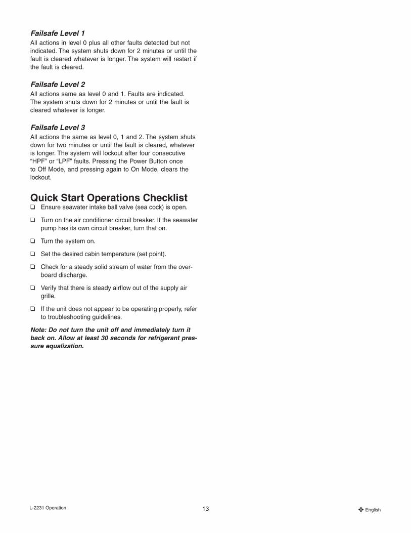
Failsafe Level 1All actions in level 0 plus all other faults detected but not indicated. The system shuts down for 2 minutes or until the fault is cleared whatever is longer. The system will restart if the fault is cleared.
Failsafe Level 2All actions same as level 0 and 1. Faults are indicated. The system shuts down for 2 minutes or until the fault is cleared whatever is longer.
Failsafe Level 3All actions the same as level 0, 1 and 2. The system shuts down for two minutes or until the fault is cleared, whatever is longer. The system will lockout after four consecutive “HPF” or “LPF” faults. Pressing the Power Button once to Off Mode, and pressing again to On Mode, clears the lockout.
Quick Start Operations Checklist❑ Ensure seawater intake ball valve (sea cock) is open.
❑ Turn on the air conditioner circuit breaker. If the seawater pump has its own circuit breaker, turn that on.
❑ Turn the system on.
❑ Set the desired cabin temperature (set point).
❑ Check for a steady solid stream of water from the over-board discharge.
❑ Verify that there is steady airflow out of the supply air grille.
❑ If the unit does not appear to be operating properly, refer to troubleshooting guidelines.
Note: Do not turn the unit off and immediately turn it back on. Allow at least 30 seconds for refrigerant pres-sure equalization.
L-2231 Troubleshooting 14 ❖ English
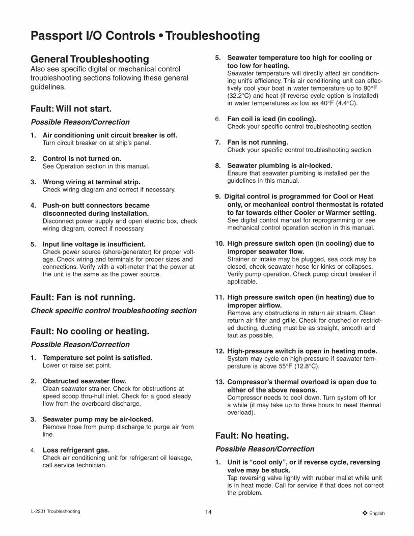
General Troubleshooting Also see specific digital or mechanical control troubleshooting sections following these general guidelines.
Fault: Will not start.Possible Reason/Correction
1. Air conditioning unit circuit breaker is off.Turn circuit breaker on at ship’s panel.
2. Control is not turned on.See Operation section in this manual.
3. Wrong wiring at terminal strip.Check wiring diagram and correct if necessary.
4. Push-on butt connectors became disconnected during installation.Disconnect power supply and open electric box, check wiring diagram, correct if necessary
5. Input line voltage is insufficient. Check power source (shore/generator) for proper volt-age. Check wiring and terminals for proper sizes and connections. Verify with a volt-meter that the power at the unit is the same as the power source.
Fault: Fan is not running.Check specific control troubleshooting section
Fault: No cooling or heating.Possible Reason/Correction
1. Temperature set point is satisfied.Lower or raise set point.
2. Obstructed seawater flow.Clean seawater strainer. Check for obstructions at speed scoop thru-hull inlet. Check for a good steady flow from the overboard discharge.
3. Seawater pump may be air-locked.Remove hose from pump discharge to purge air from line.
4. Loss refrigerant gas.Check air conditioning unit for refrigerant oil leakage, call service technician.
5. Seawater temperature too high for cooling or too low for heating.Seawater temperature will directly affect air condition-ing unit’s efficiency. This air conditioning unit can effec-tively cool your boat in water temperature up to 90°F (32.2°C) and heat (if reverse cycle option is installed) in water temperatures as low as 40°F (4.4°C).
6. Fan coil is iced (in cooling).Check your specific control troubleshooting section.
7. Fan is not running.Check your specific control troubleshooting section.
8. Seawater plumbing is air-locked.Ensure that seawater plumbing is installed per the guidelines in this manual.
9. Digital control is programmed for Cool or Heat only, or mechanical control thermostat is rotated to far towards either Cooler or Warmer setting.See digital control manual for reprogramming or see mechanical control operation section in this manual.
10. High pressure switch open (in cooling) due to improper seawater flow.Strainer or intake may be plugged, sea cock may be closed, check seawater hose for kinks or collapses. Verify pump operation. Check pump circuit breaker if applicable.
11. High pressure switch open (in heating) due to improper airflow.Remove any obstructions in return air stream. Clean return air filter and grille. Check for crushed or restrict-ed ducting, ducting must be as straight, smooth and taut as possible.
12. High-pressure switch is open in heating mode.System may cycle on high-pressure if seawater tem-perature is above 55°F (12.8°C).
13. Compressor’s thermal overload is open due to either of the above reasons.Compressor needs to cool down. Turn system off for a while (it may take up to three hours to reset thermal overload).
Fault: No heating.Possible Reason/Correction
1. Unit is “cool only”, or if reverse cycle, reversing valve may be stuck.Tap reversing valve lightly with rubber mallet while unit is in heat mode. Call for service if that does not correct the problem.
Passport I/O Controls • Troubleshooting

L-2231 Troubleshooting 15 ❖ English
Fault: Low airflow.Possible Reason/Correction
1. Airflow is blocked.Remove any obstructions in return air stream. Clean return air filter and grille. Check for crushed or restrict-ed ducting, ducting must be as straight, smooth and taut as possible.
2. Fan Coil is iced.See below.
Fault: Fan coil is iced.Possible Reason/Correction
1. Thermostat set point is too low.Raise set point.
2. Improper airflow.Remove any obstructions in return air stream. Clean return air filter and grille. Check for crushed or re-stricted ducting, must be as straight, smooth and taut as possible. See the Digital Controls Troubleshooting section below for reprogramming options.
3. Supply air is short-cycling.Redirect supply air so that is not blowing into the re-turn air stream. Seal any air leaks on duct.
4. Humidity level too high.Close hatches and doors.
5. When all else fails.Switch air conditioning unit to heat until ice melts or use hair dryer to melt.
Fault: Water coil is iced in the Heating Mode.1. Seawater temperature is below 40°F (4.4°C).
Shut down system to prevent damage to condenser. Allow coil to defrost.
Fault: System runs continuously.Possible Reason/Correction
1. Set point temperature is improperly set: too low for cooling or too high for heating.Raise or lower set point.
2. Porthole or hatches open.Close all port holes and hatches.
3. Seawater temperature too high for cooling or to low for heating.Seawater temperature will directly affect the air condi-tioning unit’s efficiency. This air conditioning unit can effectively cool your boat in water temperatures up to 90°F (32.2°C) and heat (if reverse cycle option is installed) in water as low as 40°F (4.4°C).
4. Improper air sensor location.Check your specific control troubleshooting section.
Digital Controls Troubleshooting
Fault: Digital display panel is not lit.Possible Reason/Correction
1. 8-pin display cable plugs are not making contact (unplugged, dirty, bent, or broken pins).With POWER OFF at the circuit breaker, remove con-nector and inspect. If damaged, replace connector or entire display cable.
Fault: Fan is not running or runs continuously.Possible Reason/Correction
1. Digital control is programmed for either fan cy-cling with compressor or continuous fan opera-tion.Elite Control: Press and hold the fan button for five sec-onds to change to “con” so fan will stay on continuously or to “CYC” so the fan cycles with the com-pressor.
Passport I/O Control: Reprogram parameter P-14.
Note: After the compressor cycles off, the fan will continue to run for two minutes in Cool Mode and four minutes in Heat Mode regardless of parameter setting.
Fault: Fan is not running but the compressor is.Possible Reason/Correction
1. Failed triac on Passport I/O circuit board.Send for repair or call local service technician.
L-2231 Troubleshooting 16 ❖ English
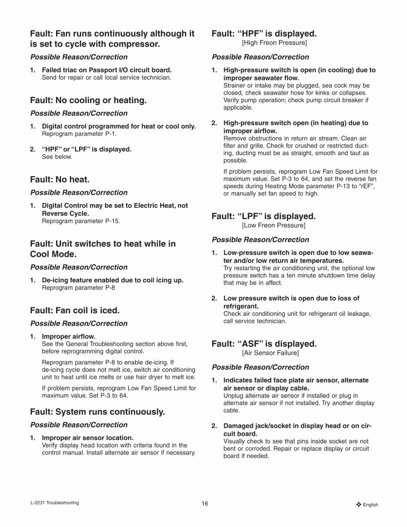
Fault: Fan runs continuously although it is set to cycle with compressor.Possible Reason/Correction
1. Failed triac on Passport I/O circuit board.Send for repair or call local service technician.
Fault: No cooling or heating.Possible Reason/Correction
1. Digital control programmed for heat or cool only.Reprogram parameter P-1.
2. “HPF” or “LPF” is displayed.See below.
Fault: No heat.Possible Reason/Correction
1. Digital Control may be set to Electric Heat, not Reverse Cycle.Reprogram parameter P-15.
Fault: Unit switches to heat while in Cool Mode.Possible Reason/Correction
1. De-icing feature enabled due to coil icing up.Reprogram parameter P-8
Fault: Fan coil is iced.Possible Reason/Correction
1. Improper airflow.See the General Troubleshooting section above first, before reprogramming digital control.
Reprogram parameter P-8 to enable de-icing. If de-icing cycle does not melt ice, switch air conditioning unit to heat until ice melts or use hair dryer to melt ice.
If problem persists, reprogram Low Fan Speed Limit for maximum value. Set P-3 to 64.
Fault: System runs continuously.Possible Reason/Correction
1. Improper air sensor location.Verify display head location with criteria found in the control manual. Install alternate air sensor if necessary.
Fault: “HPF” is displayed. [High Freon Pressure]
Possible Reason/Correction
1. High-pressure switch is open (in cooling) due to improper seawater flow.Strainer or intake may be plugged, sea cock may be closed, check seawater hose for kinks or collapses. Verify pump operation; check pump circuit breaker if applicable.
2. High-pressure switch open (in heating) due to improper airflow.Remove obstructions in return air stream. Clean air filter and grille. Check for crushed or restricted duct-ing, ducting must be as straight, smooth and taut as possible.
If problem persists, reprogram Low Fan Speed Limit for maximum value. Set P-3 to 64, and set the reverse fan speeds during Heating Mode parameter P-13 to “rEF”, or manually set fan speed to high.
Fault: “LPF” is displayed. [Low Freon Pressure]
Possible Reason/Correction
1. Low-pressure switch is open due to low seawa-ter and/or low return air temperatures.Try restarting the air conditioning unit, the optional low pressure switch has a ten minute shutdown time delay that may be in affect.
2. Low pressure switch is open due to loss of refrigerant.Check air conditioning unit for refrigerant oil leakage, call service technician.
Fault: “ASF” is displayed. [Air Sensor Failure]
Possible Reason/Correction
1. Indicates failed face plate air sensor, alternate air sensor or display cable.Unplug alternate air sensor if installed or plug in alternate air sensor if not installed. Try another display cable.
2. Damaged jack/socket in display head or on cir-cuit board. Visually check to see that pins inside socket are not bent or corroded. Repair or replace display or circuit board if needed.

L-2231 Troubleshooting 17 ❖ English
Fault: “LAC” is displayed. [Low AC Voltage]
Possible Reason/Correction
1. Supply voltage is too low.Verify power to unit with multimeter.
2. Voltage is improperly calibratedVerify that P-22 matches voltage reading to unit with a multimeter.
Fault: “PLF” is displayed. [Low Pump Flow]
Possible Reason/Correction
1. Condenser coil is too hotVerify that unit is getting water flow, and that condenser is not fouled.
2. Thermistor is damagedUnplug water sensor if installed. Try another if it is available.
3. Damaged jack/socket on circuit boardVisually check to see that pins inside socket are not bent or corroded. Repair or replace circuit board if needed.
Fault: “FIL” is flashing [Filter Replacement]
Possible Reason/Correction
1. Filter needs replacementReplace filter, and reset P-21 to “00”.

L-2231 Maintenance 18 ❖ English
Passport I/O Controls • Maintenance
Reversing ValvesReverse cycle units have a reversing valve; the valve must be energized periodically to keep the internal parts moving freely. To do this, switch the air conditioner unit into heat for a few seconds once a month.
Seawater StrainerInsure that your pump receives adequate seawater flow by regularly cleaning the strainer basket. Periodically check the overboard discharge for a steady stream of water. Check seawater intake speed scoop for obstructions. Make sure hoses are not looped, kinked or crushed.
Condenser Coil Cleaning1. With the system turned off at the circuit breaker on the
ship’s panel, disconnect the inlet and outlet connections of the condenser coil.
2. Use chemical resistant hoses (MAS white PVC 5/8" I.D., etc.) to connect the inlet of the condenser coil to the outlet of a chemical resistant, submersible pump (MAS P-500 pump, etc.) and let the hose connected to the coil outlet flow freely into the container mentioned below.
3. Place a strainer or piece of screen over the inlet of the pump and submerse the pump into a container filled with a 5% solution of muriatic or hydrochloric acid and fresh water or use a premixed over-the-counter solution. Use a large container as possible to hold the solution (5-25 gallons).
CAUTION: Avoid spilling or splashing the solution. Fol-low all warnings and recommendations given by the manufacturer of any acids or premixed solutions.
4. Power the pump and circulate the solution through the condenser coil for 15-45 minutes depending upon the size of the coils and the extent of the contamination. Visual inspection of the solution in the container should indicate when the contamination removal has stopped.
5. Circulate fresh water through the coil to flush any re-sidual acid from the system.
6. Restart the system and check operational parameters to ensure thorough cleaning has taken place. Additional cleaning may be necessary with extreme contamination.
WARNING: For the purpose of protecting the environ-ment, dispose of any contaminated acid solutions in accordance with federal, state and/or local regulations.
Return Air FiltersCheck the return air filter about once a month and clean as necessary. To clean the filter, remove it from the unit, rinse with water, air dry and reinstall.
WinterizationThere are several methods of winterization, some of which work better than others. The four various methods em-ployed using a 50/50 nonpolluting biodegradable antifreeze/water solution are:
1. Pumping of antifreeze solution into the overboard thru-hull fitting, and discharging through the intake thru-hull fitting.
2. Use of the seawater pump to pump antifreeze solution through the system and discharging through the over-board thru-hull fitting. Close sea cock, remove hose from strainer discharge, raise hose above pump (so pump does not lose its prime) and pour in antifreeze solution. Pump solution through system. The strainer and hose to sea cock will also need to be drained of water.
3. Use of pressurized air injected at the overboard dis-charge fitting and the water being discharged through the seawater intake fitting.
4. Use of pressurized air to force water from the intake through the overboard discharge.
Any method that causes the antifreeze solution to flow downward is the method of choice. By this means, the antifreeze solution will displace any water trapped and eliminate the possibility of freezing in hidden areas. In addi-tion, since the seawater pump utilizes a magnetically driven impeller, the impeller should be removed from the wet end assembly, wiped with an alcohol solution, and stored in a warm, dry area until commissioning takes place.
Note: Collect all discharged liquids and recycle or dispose of in a proper manner.
L-2231 Specifications 19 ❖ English
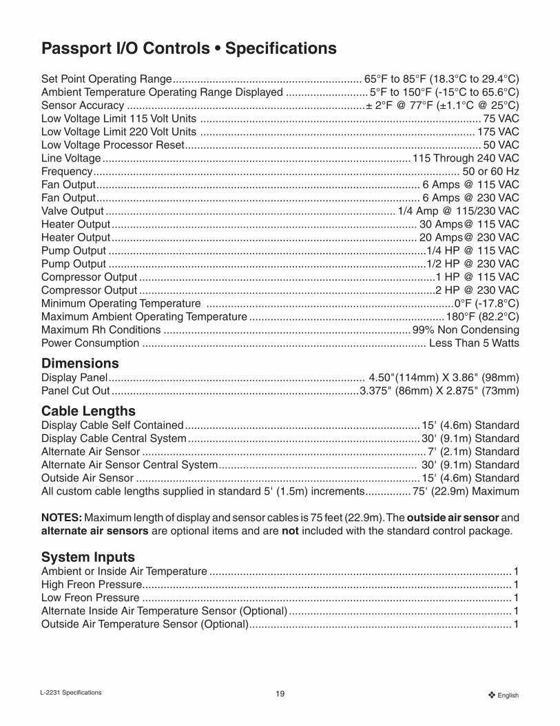
Set Point Operating Range .............................................................. 65°F to 85°F (18.3°C to 29.4°C)Ambient Temperature Operating Range Displayed ........................... 5°F to 150°F (-15°C to 65.6°C)Sensor Accuracy ..............................................................................± 2°F @ 77°F (±1.1°C @ 25°C) Low Voltage Limit 115 Volt Units ............................................................................................ 75 VACLow Voltage Limit 220 Volt Units .......................................................................................... 175 VACLow Voltage Processor Reset ................................................................................................. 50 VACLine Voltage .....................................................................................................115 Through 240 VACFrequency ........................................................................................................................ 50 or 60 HzFan Output .......................................................................................................... 6 Amps @ 115 VACFan Output .......................................................................................................... 6 Amps @ 230 VACValve Output ............................................................................................... 1/4 Amp @ 115/230 VACHeater Output .................................................................................................... 30 Amps@ 115 VACHeater Output .................................................................................................... 20 Amps@ 230 VACPump Output ........................................................................................................1/4 HP @ 115 VACPump Output ........................................................................................................1/2 HP @ 230 VACCompressor Output .................................................................................................1 HP @ 115 VACCompressor Output .................................................................................................2 HP @ 230 VACMinimum Operating Temperature .................................................................................0°F (-17.8°C)Maximum Ambient Operating Temperature ................................................................180°F (82.2°C)Maximum Rh Conditions ................................................................................. 99% Non CondensingPower Consumption ............................................................................................. Less Than 5 Watts
DimensionsDisplay Panel .................................................................................... 4.50"(114mm) X 3.86" (98mm) Panel Cut Out .................................................................................3.375" (86mm) X 2.875" (73mm)
Cable LengthsDisplay Cable Self Contained ............................................................................. 15' (4.6m) StandardDisplay Cable Central System ............................................................................ 30' (9.1m) StandardAlternate Air Sensor ............................................................................................. 7' (2.1m) StandardAlternate Air Sensor Central System ................................................................. 30' (9.1m) Standard Outside Air Sensor ............................................................................................. 15' (4.6m) StandardAll custom cable lengths supplied in standard 5' (1.5m) increments ............... 75' (22.9m) Maximum
NOTES: Maximum length of display and sensor cables is 75 feet (22.9m). The outside air sensor and alternate air sensors are optional items and are not included with the standard control package.
System InputsAmbient or Inside Air Temperature ................................................................................................... 1High Freon Pressure......................................................................................................................... 1Low Freon Pressure ......................................................................................................................... 1Alternate Inside Air Temperature Sensor (Optional) ......................................................................... 1Outside Air Temperature Sensor (Optional) ...................................................................................... 1
Passport I/O Controls • Specifications

L-2231 Specifications 20 ❖ English
Automated Factory Self Test ProgramThe Passport I/O software contains a self test program to facilitate factory testing of the entire air conditioning sys-tem. Once the self test program is activated, the test cycle will continue until the AC power is interrupted or the Power Button is pressed once which returns the system to the Off Mode.
Activate the self test program by pressing the Power Button while turning on the AC power. Release the Power Button while the display indicates “888” and all LEDs are lit. Pass-port I/O is now in the self test program.
“tSt” appears in the display while in the self test program.
Once activated the self test software will continuously execute the following procedure:
1. Turn on in the Heat Mode and supply heating for ten minutes.
2. Stop heating and run the fan only for five minutes.
3. Switch to Cool Mode and continue cooling for ten minutes.
4. Stop cooling and run the fan only for five minutes.
5. Return to step one and continue until interrupted.
The self test program will continue until the power is inter-rupted or the test is halted by pressing the Power Button once.
Service ToolsHour MeterTotal compressor cycle time is saved in EEPROM every six minutes of continuous compressor running time. Cycles less than six minutes are discarded to conserve memory and allow the most flexible hour-meter possible.
To view the hour meter turn off the AC power and press the Down Button. While holding the Down Button, restore AC power. After Power-On Reset is complete, the following appears in the display:
1. “Hr” is displayed for one second.
2. The display blanks out for one second then displays the thousands of hours for three seconds.
3. The display blanks out for one second then displays the hundreds units for three seconds.
4. The unit returns to the last operating state before power was removed.
Maximum recorded time is 65,536 hours, the meter stops and can only be reset by a service technician.
Service History LogPassport I/O records and remembers the eight most recent faults. Each time a fault is detected, a one hour timer is started. Three consecutive faults within that hour cause system shut down, lock out and display the fault code. During that hour, to conserve memory, the same recurring fault is not recorded in the service history log. Continuous operation for one hour without the same recurring fault clears that fault counter but the event remains in the ser-vice history log until over written. Should a different fault be detected during the hour, it will be entered into the service history log.
The following events are entered into the service history log:
• High Freon Pressure
• Low Freon Pressure
• Air Sensor Fault
To view the service history log turn off the AC power and press the Fan Button. With the Fan Button pressed turn on the AC power. Once Power On Reset is completed (display indicates “888” and all LEDs are lit) release the Fan Button.
The display will flash the most recent fault detected, fol-lowed by the event chronology number. To view other events detected press either the Up or Down Buttons.
The service history log can be cleared by simultaneously pressing the Power and Down buttons.
Exit the service history log by pressing either the Power or Select Buttons or wait thirty seconds without pressing any button.

L-2231 Installation 21 ❖ English
Sample Wiring Diagram
NOTE: THIS IS A SAMPLE DIAGRAM. WIRE COLORS MAY VARY. SEE UNIT SPECIFIC DIAGRAM LOCATED IN ELECTRICAL BOX OR IN AIR CONDITIONING UNIT MANUAL.
TURN POWER OFF BEFORE OPENING ELECTRICAL BOX.
See Parameter P-15 for more information on Electric Heat
22 ❖ English L-2231
The following warranty is extended to cover marine air conditioners manufactured or supplied by Dometic Environ-mental Corporation, and is subject to qualifications indi-cated. Dometic warrants for the periods set forth below that products manufactured or supplied by it will be free from defects in workmanship and material, provided such prod-ucts are installed, operated, and maintained in accordance with Dometic’s written instruction.
ALL IMPLIED WARRANTIES INCLUDING MERCHANT-ABILITY AND FITNESS FOR A PARTICULAR PURPOSE, ARE LIMITED TO THE TERMS AND PERIODS OF WAR-RANTY SET FORTH BELOW AND, TO THE EXTENT PERMITTED BY LAW, ANY AND ALL IMPLIED WARRAN-TIES ARE EXCLUDED.
Warranty with the Elite or Passport I/O digital controls (NOT TO INCLUDE THE VECTOR TURBO SYSTEMS DATING FROM 2007. SEE SEPARATE WARRANTY FOR THIS SYSTEM ON THE FOLLOWING PAGE): (Coverage applies to units manufactured on or after 03/01/03 and ap-plies only to units equipped with Elite or Passport I/O digi-tal controls at the Dometic factory.) Components compris-ing of the Passport I/O circuit boards, Elite or Passport I/O digital displays, and associated cables are warranted for a period of three (3) years from the date of installation, but not to exceed four (4) years from the date of manufacture at the Dometic factory. All other components comprising a complete system (excluding pumps and pump relay panels) on a new installation are warranted for a period of two (2) years from the date of installation, but not to exceed three (3) years from the date of manufacture at the Dometic factory. Pumps and pump relay panels are warranted for a period of one (1) year from the date of installation, but not to exceed two (2) years from the date of purchase. OEM installed equipment warranties begin with the purchase of the vessel, not from the date of installation.
Warranty with MCP (Mechanical Control Panel) control: Components comprising a complete system on a new installation are warranted for a period of one (1) year from the date of installation, but not to exceed two (2) years from the date of manufacture at the Dometic factory. OEM installed equipment warranties begin with the purchase of the vessel, not from the date of installation.
Passport I/O Controls • Manufacturers Limited Warranty Agreement
In addition, Dometic will pay labor costs and travel as outlined in its Schedule of Limited Warranty Allowances for removal and reinstallation of such components for a period of one (1) year from the date of installation, but not to exceed two (2) years from the date of manufacture at the Dometic factory. OEM installed equipment warranties begin with the purchase of the vessel, not from the date of installation. Warranty will be paid in accordance with our established schedule of allowances. Compensation for war-ranty repairs is only made to Dometic authorized service companies.
Dometic will repair, or replace at its option, components found to be defective due to faulty materials or workman-ship, when such components, examined by an authorized service dealer or a factory service representative, are found to have a defect for which the company is respon-sible. Refer to Manufacturer’s Limited Warranty Policy for complete coverage and exclusions. Replacement components are warranted for the duration of the remain-ing warranty period in effect on the original component. In the event that a unit has to be returned to the factory, it must be properly packaged to prevent shipping dam-ages. If packaging is not available, Dometic will provide it at no charge. The warranty may be voided on any piece of equipment or component that is damaged due to improper packaging.
This limited warranty is extended in lieu of all other warran-ties, agreements or obligations, expressed or implied, con-cerning Dometic’s components. This warranty is extended only to the original purchaser and is not transferable. This warranty shall be governed by the laws of the State of Florida and gives the original first end user definite legal rights.
This warranty does not cover damages incidental and/or consequential to the failure of Dometic’s equipment includ-ing but not limited to; normal wear, accident, misuse, abuse, negligence, improper installation, lack of reasonable and necessary maintenance, alteration, civil disturbance or acts of God.
No person or dealer is authorized to extend any other warranties or to assume any other liabilities on Dometic’s behalf, unless made or assumed in writing by an officer of Dometic.

23 ❖ English L-2231
Marine Air Vector Turbo • Manufacturer’s Limited Warranty
1. Warranty. Dometic Environmental Corporation (“Dometic”) warrants to the retail purchaser (“Purchaser”, including subsequent owners) who purchases a new Marine Air Vector Turbo marine air conditioner manufactured by Dometic (the “Product”, including a Marine Air Vector Turbo marine air conditioner which has been incorporated in a marine vessel by an original equipment manufacturer (“OEM”)), that the Product shall be free from defects in materials and workmanship for the periods and coverages set forth below:
Product or Part Term CoverageEntire Product 1 Year* Parts and labor**Compressor and the base pan, evaporator shroud and blower ring of the chassis.
4 Years (starting at the expira-tion of the initial one (1) year warranty period above)
Parts only
*The warranty period commences on the date of installation of the Product, but shall not exceed three (3) years from the date of manufacture of the Product by Dometic. The warranty on OEM installed Products commences with the initial retail purchase of the vessel, not with the date of installation.
**Dometic will pay for labor for the repair or replacement performed by an authorized Dometic dealer or factory representative at the rates then allowed by Dometic for warranty repairs.
Dometic will repair, or replace at its sole option, the Product or components found to be defective due to faulty materials or workmanship, when such components, examined by an authorized service dealer or a factory service representative, are found to have a defect for which Dometic is responsible. Replacement components are warranted for the duration of the remaining warranty period in effect on the original component. In the event that a unit has to be returned to the factory, it must be properly packaged to prevent shipping damages. The warranty may be voided on any piece of equipment or com-ponent that is damaged due to improper packaging. Purchaser must provide notice of the defect to Dometic Environmental Corporation, 2000 N. Andrews Avenue Ext., Pompano Beach, Florida 33069 or to one of its Authorized Service Dealers within sixty (60) days after discovery of a purported defect in or to the Product covered by this warranty. Failure to timely provide this notice to Dometic or one of its Authorized Service Dealers shall constitute a waiver of Purchaser’s warranty rights.
2. Exclusions from Warranty Coverage. This warranty excludes liability for defects in or damages to a Product caused di-rectly or indirectly by the following: (i) improper installation; (2) additions, alterations, or installations made by persons other than Dometic or its authorized dealers or representatives; (iii) normal wear and usage or conditions resulting from the failure to perform regular maintenance and care; (iv) abuse or misuse of the product, or uses that it was not intended for; (v) minor imperfections or defects that do not materially impair or affect its suitability for intended use; (vi) damage resulting from an act of God, power surge, lightening, submersion, improper wiring or improper power supply; and (vii) complaints of noise and vibration.
3. Exclusion of Implied Warranties and Limitations on Damages. THE WARRANTY PROVIDED BY DOMETIC HEREIN CONSTITUTES PURCHASER’S SOLE AND EXCLUSIVE REMEDY FOR DEFECTS RELATING TO THE PRODUCT. DO-METIC MAKES NO OTHER REPRESENTATIONS OR WARRANTIES OF ANY KIND EXCEPT AS EXPRESSLY STATED HEREIN. DOMETIC DISCLAIMS ANY AND ALL IMPLIED WARRANTIES, INCLUDING THE WARRANTY OF MERCHANT-ABILITY AND THE WARRANTY OF FITNESS FOR A PARTICULAR PURPOSE. TO THE FULLEST EXTENT PERMITTED BY APPLICABLE LAW, DOMETIC SHALL NOT BE LIABLE TO PURCHASER FOR ANY CONSEQUENTIAL, INCIDENTAL, EXEMPLARY, PUNITIVE, SPECIAL, OR INDIRECT DAMAGES. DOMETIC FURTHER SHALL NOT BE LIABLE FOR ANY DAMAGES WHICH ARE BASED ON NEGLIGENCE, BREACH OF WARRANTY, OR STRICT LIABILITY, EXCEPT AS EX-PRESSLY PROVIDED HEREIN. DOMETIC’S LIABILITY HEREUNDER SHALL IN NO EVENT EXCEED THE PURCHASE PRICE OF THE DEFECTIVE PRODUCT. THIS WARRANTY MAY NOT BE MODIFIED UNLESS AN AUTHORIZED REP-RESENTATIVE OF DOMETIC SIGNS A WRITTEN AUTHORIZATION FOR A MODIFICATION. SOME STATES DO NOT ALLOW EXCLUSION OR LIMITATION OF INCIDENTAL OR CONSEQUENTIAL DAMAGES, SO THE ABOVE EXCLUSION OR LIMITATION MAY NOT APPLY TO YOU.
Revised 6/29/07
ELDS01 GKC 207017v4
Marine Air Worldwide Service Dealer Locator
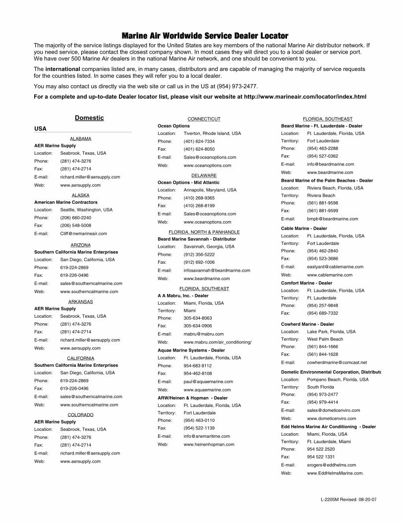
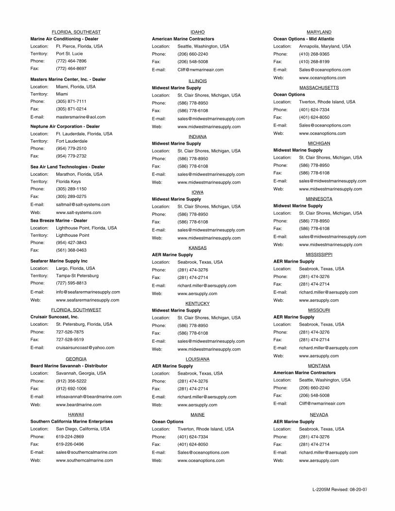
Marine Air Worldwide Service Dealer LocatorThe majority of the service listings displayed for the United States are key members of the national Marine Air distributor network. If you need service, please contact the closest company shown. In most cases they will direct you to a local dealer or service port. We have over 500 Marine Air dealers in the national Marine Air network, and one should be convenient to you.
The international companies listed are, in many cases, distributors and are capable of managing the majority of service requests for the countries listed. In some cases they will refer you to a local dealer.
You may also contact us directly via the web site or call us in the US at (954) 973-2477.
For a complete and up-to-date Dealer locator list, please visit our website at http://www.marineair.com/locator/index.html
DomesticUSA
ALABAMA
AER Marine Supply
(281) 474-3276
(281) 474-2714
www.aersupply.com
Phone:
Fax:
Seabrook, Texas, USA
E-mail:
Web:
Location:
ALASKA
American Marine Contractors
(206) 660-2240
(206) 548-5008
Phone:
Fax:
Seattle, Washington, USA
E-mail:
Location:
ARIZONA
Southern California Marine Enterprises
619-224-2869
619-226-0496
www.southerncalmarine.com
Phone:
Fax:
San Diego, California, USA
E-mail:
Web:
Location:
ARKANSAS
AER Marine Supply
(281) 474-3276
(281) 474-2714
www.aersupply.com
Phone:
Fax:
Seabrook, Texas, USA
E-mail:
Web:
Location:
CALIFORNIA
Southern California Marine Enterprises
619-224-2869
619-226-0496
www.southerncalmarine.com
Phone:
Fax:
San Diego, California, USA
E-mail:
Web:
Location:
COLORADO
AER Marine Supply
(281) 474-3276
(281) 474-2714
www.aersupply.com
Phone:
Fax:
Seabrook, Texas, USA
E-mail:
Web:
Location:
CONNECTICUT
Ocean Options
(401) 624-7334
(401) 624-8050
www.oceanoptions.com
Phone:
Fax:
Tiverton, Rhode Island, USA
E-mail:
Web:
Location:
DELAWARE
Ocean Options - Mid Atlantic
(410) 268-9365
(410) 268-8199
www.oceanoptions.com
Phone:
Fax:
Annapolis, Maryland, USA
E-mail:
Web:
Location:
FLORIDA, NORTH & PANHANDLE
Beard Marine Savannah - Distributor
(912) 356-5222
(912) 692-1006
www.beardmarine.com
Phone:
Fax:
Savannah, Georgia, USA
E-mail:
Web:
Location:
FLORIDA, SOUTHEAST
Miami
A A Mabru, Inc. - Dealer
305-634-8063
305-634-0906
www.mabru.com/air_conditioning/
Phone:
Fax:
Miami, Florida, USA
E-mail:
Web:
Location:
Territory:
Aquae Marine Systems - Dealer
954-683 8112
954-462-8108
www.aquaemarine.com
Phone:
Fax:
Ft. Lauderdale, Florida, USA
E-mail:
Web:
Location:
Fort Lauderdale
ARW/Heinen & Hopman - Dealer
(954) 463-0110
(954) 522-1139
www.heinenhopman.com
Phone:
Fax:
Ft. Lauderdale, Florida, USA
E-mail:
Web:
Location:
Territory:
FLORIDA, SOUTHEAST
Fort Lauderdale
Beard Marine - Ft. Lauderdale - Dealer
(954) 463-2288
(954) 527-0362
www.beardmarine.com
Phone:
Fax:
Ft. Lauderdale, Florida, USA
E-mail:
Web:
Location:
Territory:
Riviera Beach
Beard Marine of the Palm Beaches - Dealer
(561) 881-9598
(561) 881-9599
Phone:
Fax:
Riviera Beach, Florida, USA
E-mail:
Location:
Territory:
Fort Lauderdale
Cable Marine - Dealer
(954) 462-2840
(954) 523-3686
www.cablemarine.com
Phone:
Fax:
Ft. Lauderdale, Florida, USA
E-mail:
Web:
Location:
Territory:
Ft. Lauderdale
Comfort Marine - Dealer
(954) 257-9848
(954) 689-7332
Phone:
Fax:
Ft. Lauderdale, Florida, USALocation:
Territory:
West Palm Beach
Cowherd Marine - Dealer
(561) 844-1666
(561) 844-1628
Phone:
Fax:
Lake Park, Florida, USA
E-mail:
Location:
Territory:
South Florida
Dometic Environmental Corporation, Distributor
(954) 973-2477
(954) 979-4414
www.dometicenviro.com
Phone:
Fax:
Pompano Beach, Florida, USA
E-mail:
Web:
Location:
Territory:
Ft. Lauderdale, Miami
Edd Helms Marine Air Conditioning - Dealer
954 522 2520
954 522 1331
www.EddHelmsMarine.com.
Phone:
Fax:
Miami, Florida, USA
E-mail:
Web:
Location:
Territory:
L-2205M Revised: 08-20-07
FLORIDA, SOUTHEAST
Port St. Lucie
Marine Air Conditioning - Dealer
(772) 464-7896
(772) 464-8697
Phone:
Fax:
Ft. Pierce, Florida, USALocation:
Territory:
Miami
Masters Marine Center, Inc. - Dealer
(305) 871-7111
(305) 871-0214
Phone:
Fax:
Miami, Florida, USA
E-mail:
Location:
Territory:
Fort Lauderdale
Neptune Air Corporation - Dealer
(954) 779-2510
(954) 779-2732
Phone:
Fax:
Ft. Lauderdale, Florida, USALocation:
Territory:
Florida Keys
Sea Air Land Technologies - Dealer
(305) 289-1150
(305) 289-0275
www.salt-systems.com
Phone:
Fax:
Marathon, Florida, USA
E-mail:
Web:
Location:
Territory:
Lighthouse Point
Sea Breeze Marine - Dealer
(954) 427-3843
(561) 368-0463
Phone:
Fax:
Lighthouse Point, Florida, USALocation:
Territory:
Tampa-St Petersburg
Seafarer Marine Supply Inc
(727) 595-8813
www.seafarermarinesupply.com
Phone:
Largo, Florida, USA
E-mail:
Web:
Location:
Territory:
FLORIDA, SOUTHWEST
Cruisair Suncoast, Inc.
727-526-7875
727-528-9519
Phone:
Fax:
St. Petersburg, Florida, USA
E-mail:
Location:
GEORGIA
Beard Marine Savannah - Distributor
(912) 356-5222
(912) 692-1006
www.beardmarine.com
Phone:
Fax:
Savannah, Georgia, USA
E-mail:
Web:
Location:
HAWAII
Southern California Marine Enterprises
619-224-2869
619-226-0496
www.southerncalmarine.com
Phone:
Fax:
San Diego, California, USA
E-mail:
Web:
Location:
IDAHO
American Marine Contractors
(206) 660-2240
(206) 548-5008
Phone:
Fax:
Seattle, Washington, USA
E-mail:
Location:
ILLINOIS
Midwest Marine Supply
(586) 778-8950
(586) 778-6108
www.midwestmarinesupply.com
Phone:
Fax:
St. Clair Shores, Michigan, USA
E-mail:
Web:
Location:
INDIANA
Midwest Marine Supply
(586) 778-8950
(586) 778-6108
www.midwestmarinesupply.com
Phone:
Fax:
St. Clair Shores, Michigan, USA
E-mail:
Web:
Location:
IOWA
Midwest Marine Supply
(586) 778-8950
(586) 778-6108
www.midwestmarinesupply.com
Phone:
Fax:
St. Clair Shores, Michigan, USA
E-mail:
Web:
Location:
KANSAS
AER Marine Supply
(281) 474-3276
(281) 474-2714
www.aersupply.com
Phone:
Fax:
Seabrook, Texas, USA
E-mail:
Web:
Location:
KENTUCKY
Midwest Marine Supply
(586) 778-8950
(586) 778-6108
www.midwestmarinesupply.com
Phone:
Fax:
St. Clair Shores, Michigan, USA
E-mail:
Web:
Location:
LOUISIANA
AER Marine Supply
(281) 474-3276
(281) 474-2714
www.aersupply.com
Phone:
Fax:
Seabrook, Texas, USA
E-mail:
Web:
Location:
MAINE
Ocean Options
(401) 624-7334
(401) 624-8050
www.oceanoptions.com
Phone:
Fax:
Tiverton, Rhode Island, USA
E-mail:
Web:
Location:
MARYLAND
Ocean Options - Mid Atlantic
(410) 268-9365
(410) 268-8199
www.oceanoptions.com
Phone:
Fax:
Annapolis, Maryland, USA
E-mail:
Web:
Location:
MASSACHUSETTS
Ocean Options
(401) 624-7334
(401) 624-8050
www.oceanoptions.com
Phone:
Fax:
Tiverton, Rhode Island, USA
E-mail:
Web:
Location:
MICHIGAN
Midwest Marine Supply
(586) 778-8950
(586) 778-6108
www.midwestmarinesupply.com
Phone:
Fax:
St. Clair Shores, Michigan, USA
E-mail:
Web:
Location:
MINNESOTA
Midwest Marine Supply
(586) 778-8950
(586) 778-6108
www.midwestmarinesupply.com
Phone:
Fax:
St. Clair Shores, Michigan, USA
E-mail:
Web:
Location:
MISSISSIPPI
AER Marine Supply
(281) 474-3276
(281) 474-2714
www.aersupply.com
Phone:
Fax:
Seabrook, Texas, USA
E-mail:
Web:
Location:
MISSOURI
AER Marine Supply
(281) 474-3276
(281) 474-2714
www.aersupply.com
Phone:
Fax:
Seabrook, Texas, USA
E-mail:
Web:
Location:
MONTANA
American Marine Contractors
(206) 660-2240
(206) 548-5008
Phone:
Fax:
Seattle, Washington, USA
E-mail:
Location:
NEVADA
AER Marine Supply
(281) 474-3276
(281) 474-2714
www.aersupply.com
Phone:
Fax:
Seabrook, Texas, USA
E-mail:
Web:
Location:
L-2205M Revised: 08-20-07

NEW HAMPSHIRE
Ocean Options
(401) 624-7334
(401) 624-8050
www.oceanoptions.com
Phone:
Fax:
Tiverton, Rhode Island, USA
E-mail:
Web:
Location:
NEW JERSEY
New York, New Jersey
Marine Specialists
(631) 580-0545
(631) 580-0551
www.marinespecialists.com
Phone:
Fax:
Ronkonkoma, New York, USA
E-mail:
Web:
Location:
Territory:
NEW MEXICO
AER Marine Supply
(281) 474-3276
(281) 474-2714
www.aersupply.com
Phone:
Fax:
Seabrook, Texas, USA
E-mail:
Web:
Location:
NEW YORK
New York, New Jersey
Marine Specialists
(631) 580-0545
(631) 580-0551
www.marinespecialists.com
Phone:
Fax:
Ronkonkoma, New York, USA
E-mail:
Web:
Location:
Territory:
NORTH CAROLINA
Beard Marine Savannah - Distributor
(912) 356-5222
(912) 692-1006
www.beardmarine.com
Phone:
Fax:
Savannah, Georgia, USA
E-mail:
Web:
Location:
NORTH DAKOTA
Midwest Marine Supply
(586) 778-8950
(586) 778-6108
www.midwestmarinesupply.com
Phone:
Fax:
St. Clair Shores, Michigan, USA
E-mail:
Web:
Location:
OHIO
Midwest Marine Supply
(586) 778-8950
(586) 778-6108
www.midwestmarinesupply.com
Phone:
Fax:
St. Clair Shores, Michigan, USA
E-mail:
Web:
Location:
OKLAHOMA
AER Marine Supply
(281) 474-3276
(281) 474-2714
www.aersupply.com
Phone:
Fax:
Seabrook, Texas, USA
E-mail:
Web:
Location:
OREGON
American Marine Contractors
(206) 660-2240
(206) 548-5008
Phone:
Fax:
Seattle, Washington, USA
E-mail:
Location:
PENNSYLVANIA
Ocean Options - Mid Atlantic
(410) 268-9365
(410) 268-8199
www.oceanoptions.com
Phone:
Fax:
Annapolis, Maryland, USA
E-mail:
Web:
Location:
RHODE ISLAND
Ocean Options
(401) 624-7334
(401) 624-8050
www.oceanoptions.com
Phone:
Fax:
Tiverton, Rhode Island, USA
E-mail:
Web:
Location:
SOUTH CAROLINA
Beard Marine Savannah - Distributor
(912) 356-5222
(912) 692-1006
www.beardmarine.com
Phone:
Fax:
Savannah, Georgia, USA
E-mail:
Web:
Location:
SOUTH DAKOTA
Midwest Marine Supply
(586) 778-8950
(586) 778-6108
www.midwestmarinesupply.com
Phone:
Fax:
St. Clair Shores, Michigan, USA
E-mail:
Web:
Location:
TENNESSEE
Beard Marine Savannah - Distributor
(912) 356-5222
(912) 692-1006
www.beardmarine.com
Phone:
Fax:
Savannah, Georgia, USA
E-mail:
Web:
Location:
TEXAS
AER Marine Supply
(281) 474-3276
(281) 474-2714
www.aersupply.com
Phone:
Fax:
Seabrook, Texas, USA
E-mail:
Web:
Location:
UTAH
AER Marine Supply
(281) 474-3276
(281) 474-2714
www.aersupply.com
Phone:
Fax:
Seabrook, Texas, USA
E-mail:
Web:
Location:
VERMONT
Ocean Options
(401) 624-7334
(401) 624-8050
www.oceanoptions.com
Phone:
Fax:
Tiverton, Rhode Island, USA
E-mail:
Web:
Location:
VIRGINIA
Ocean Options - Mid Atlantic
(410) 268-9365
(410) 268-8199
www.oceanoptions.com
Phone:
Fax:
Annapolis, Maryland, USA
E-mail:
Web:
Location:
WASHINGTON
American Marine Contractors
(206) 660-2240
(206) 548-5008
Phone:
Fax:
Seattle, Washington, USA
E-mail:
Location:
WEST VIRGINIA
Ocean Options - Mid Atlantic
(410) 268-9365
(410) 268-8199
www.oceanoptions.com
Phone:
Fax:
Annapolis, Maryland, USA
E-mail:
Web:
Location:
WISCONSIN
Midwest Marine Supply
(586) 778-8950
(586) 778-6108
www.midwestmarinesupply.com
Phone:
Fax:
St. Clair Shores, Michigan, USA
E-mail:
Web:
Location:
WYOMING
American Marine Contractors
(206) 660-2240
(206) 548-5008
Phone:
Fax:
Seattle, Washington, USA
E-mail:
Location:
InternationalArgentina
Baron SRL
(54) 11-4-580-5556
(54) 11-4-746-1696
www.baron.com.ar
Phone:
Fax:
San Fernando, Buenos Aires, Argentina
E-mail:
Web:
Location:
Australia
Seairland Systems, Inc.
(61) 7-3268-7511
(61) 7-3268-1445
Phone:
Fax:
Brisbane, Queensland, Australia
E-mail:
Location:
L-2205M Revised: 08-20-07

Bahamas
Bradford Grand Bahama, Ltd.
+242-352-7711
+242-352-7695
www.bradford-grand-bahama.com
Phone:
Fax:
Freeport, Grand Bahama, Bahamas
E-mail:
Web:
Location:
Nassau
Freezing Point, Ltd.
(242) 325-3589
(242) 356-5271
Phone:
Fax:
Nassau, Bahamas
E-mail:
Location:
Territory:
Bahrain
Mantech
+(971) 4-3332-542
+(971) 4-3330-649
Phone:
Fax:
Dubai, United Arab Emirates
E-mail:
Location:
Brazil
Marine Express
55-11-5182-7166
55-11-5183-3636
www.marinexpress.com.br
Phone:
Fax:
Sao Paulo, Brazil
E-mail:
Web:
Location:
British Virgin Islands
BVI Marine Management
(284) 494-2938
(284) 494-5006
Phone:
Fax:
Roadtown, Tortola, British Virgin Islands
E-mail:
Location:
C & G Refrigeration
(284) 776-0038Phone:
, Tortola, British Virgin IslandsLocation:
Parts And Power
284-494-2830
284-494-1584
www.partsandpower.com
Phone:
Fax:
Tortola, British Virgin Islands
E-mail:
Web:
Location:
British West Indies
Caribbean Marine & Diesel
649-941-5903
649-941-5902
Phone:
Fax:
Turks and Caicos Islands, British West Indies
E-mail:
Location:
Canada
BRITISH COLUMBIA
American Marine Contractors
(206) 660-2240
(206) 548-5008
Phone:
Fax:
Seattle, Washington, USA
E-mail:
Location:
ONTARIO
Queensville
Northland Supply Company
(905) 478-2244
(905) 478-2295
www.norsupco.com
Phone:
Fax:
Queensville, Ontario, Canada
E-mail:
Web:
Location:
Territory:
All Canadian Provinces except BC
Woodard and Company - Manufacturer's Rep.
(905)760-0245
(905)760-0250
Phone:
Fax:
Concord, Ontario, Canada
E-mail:
Location:
Territory:
QUEBEC
Drummondville, Quebec
Kimpex, Inc.
(705) 721-0947
(705) 721-1704
http://www.kpx-kimpex.com
Phone:
Fax:
Drummondville, Quebec, Canada
E-mail:
Web:
Location:
Territory:
Caribbean Islands
BVI Marine Management
(284) 494-2938
(284) 494-5006
Phone:
Fax:
Roadtown, Tortola, British Virgin Islands
E-mail:
Location:
C & G Refrigeration
(284) 776-0038Phone:
, Tortola, British Virgin IslandsLocation:
Caraibe Greemant
596 596 74 80 33
Phone:
Le Marin, Martinique, French West Indies
E-mail:
Location:
Caribbean Marine & Diesel
649-941-5903
649-941-5902
Phone:
Fax:
Turks and Caicos Islands, British West Indies
E-mail:
Location:
Centro Cruisair de Puerto Rico
787-727-3637
787-727-3637
Phone:
Fax:
Santurce, Puerto Rico
E-mail:
Location:
Cool-Tech Air Condition
(787) 860-2615
(787) 801-2050
http://www.cooltechac.com/
Phone:
Fax:
Fajardo, Puerto Rico
E-mail:
Web:
Location:
Enertech N.V.
+599-551-2145
+599-544-4608
www.enertechnv.com
Phone:
Fax:
Simpson Bay, St. Maarten/St. Martin, Netherlands Antilles
E-mail:
Web:
Location:
Nassau
Freezing Point, Ltd.
(242) 325-3589
(242) 356-5271
Phone:
Fax:
Nassau, Bahamas
E-mail:
Location:
Territory:
Frostline
599 522 9610 (Technical)
599 544 3263
[email protected] (technical);
Phone:
Fax:
Cole Bay, St. Maarten/St. Martin, Netherlands Antilles
E-mail:
Location:
Iceberg Refrigeration
590-24 35 35
590-24 35 35
Phone:
Fax:
Guadeloupe, French West IndiesLocation:
May Day Marine
787-637-0756
787-790-2551
Phone:
Fax:
San Juan, Puerto RicoLocation:
Nau-T-Kol Marine Refrigeration
868-634-2174
868-634-2174
www.nautkol.com
Phone:
Fax:
Chaguaramas, Trinidad
E-mail:
Web:
Location:
Otis Air Conditioning Ltd.
+(345) 945 7167
Phone:
Georgetown, Grand Cayman
E-mail:
Location:
Reefco, Inc.
(340) 776-0038
(340) 776-0038
www.reefco.net
Phone:
Fax:
St. Thomas, US Virgin Islands
E-mail:
Web:
Location:
Regis Electronics (St Lucia) LTD.
758-452-0205
758-452-0206
www.regiselectronics.com
Phone:
Fax:
St. Lucia, West Indies
E-mail:
Web:
Location:
L-2205M Revised: 08-20-07
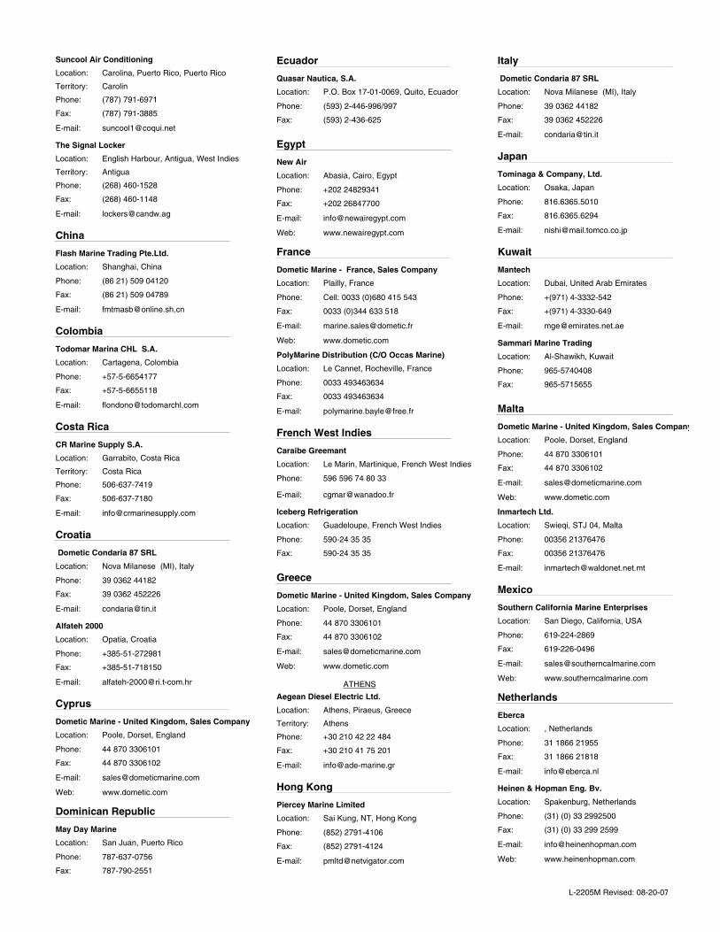
Carolin
Suncool Air Conditioning
(787) 791-6971
(787) 791-3885
Phone:
Fax:
Carolina, Puerto Rico, Puerto Rico
E-mail:
Location:
Territory:
Antigua
The Signal Locker
(268) 460-1528
(268) 460-1148
Phone:
Fax:
English Harbour, Antigua, West Indies
E-mail:
Location:
Territory:
China
Flash Marine Trading Pte.Ltd.
(86 21) 509 04120
(86 21) 509 04789
Phone:
Fax:
Shanghai, China
E-mail:
Location:
Colombia
Todomar Marina CHL S.A.
+57-5-6654177
+57-5-6655118
Phone:
Fax:
Cartagena, Colombia
E-mail:
Location:
Costa Rica
Costa Rica
CR Marine Supply S.A.
506-637-7419
506-637-7180
Phone:
Fax:
Garrabito, Costa Rica
E-mail:
Location:
Territory:
Croatia
Dometic Condaria 87 SRL
39 0362 44182
39 0362 452226
Phone:
Fax:
Nova Milanese (MI), Italy
E-mail:
Location:
Alfateh 2000
+385-51-272981
+385-51-718150
Phone:
Fax:
Opatia, Croatia
E-mail:
Location:
Cyprus
Dometic Marine - United Kingdom, Sales Company
44 870 3306101
44 870 3306102
www.dometic.com
Phone:
Fax:
Poole, Dorset, England
E-mail:
Web:
Location:
Dominican Republic
May Day Marine
787-637-0756
787-790-2551
Phone:
Fax:
San Juan, Puerto RicoLocation:
Ecuador
Quasar Nautica, S.A.
(593) 2-446-996/997
(593) 2-436-625
Phone:
Fax:
P.O. Box 17-01-0069, Quito, EcuadorLocation:
Egypt
New Air
+202 24829341
+202 26847700
www.newairegypt.com
Phone:
Fax:
Abasia, Cairo, Egypt
E-mail:
Web:
Location:
France
Dometic Marine - France, Sales Company
Cell: 0033 (0)680 415 543
0033 (0)344 633 518
www.dometic.com
Phone:
Fax:
Plailly, France
E-mail:
Web:
Location:
PolyMarine Distribution (C/O Occas Marine)
0033 493463634
0033 493463634
Phone:
Fax:
Le Cannet, Rocheville, France
E-mail:
Location:
French West Indies
Caraibe Greemant
596 596 74 80 33
Phone:
Le Marin, Martinique, French West Indies
E-mail:
Location:
Iceberg Refrigeration
590-24 35 35
590-24 35 35
Phone:
Fax:
Guadeloupe, French West IndiesLocation:
Greece
Dometic Marine - United Kingdom, Sales Company
44 870 3306101
44 870 3306102
www.dometic.com
Phone:
Fax:
Poole, Dorset, England
E-mail:
Web:
Location:
ATHENS
Athens
Aegean Diesel Electric Ltd.
+30 210 42 22 484
+30 210 41 75 201
Phone:
Fax:
Athens, Piraeus, Greece
E-mail:
Location:
Territory:
Hong Kong
Piercey Marine Limited
(852) 2791-4106
(852) 2791-4124
Phone:
Fax:
Sai Kung, NT, Hong Kong
E-mail:
Location:
Italy
Dometic Condaria 87 SRL
39 0362 44182
39 0362 452226
Phone:
Fax:
Nova Milanese (MI), Italy
E-mail:
Location:
Japan
Tominaga & Company, Ltd.
816.6365.5010
816.6365.6294
Phone:
Fax:
Osaka, Japan
E-mail:
Location:
Kuwait
Mantech
+(971) 4-3332-542
+(971) 4-3330-649
Phone:
Fax:
Dubai, United Arab Emirates
E-mail:
Location:
Sammari Marine Trading
965-5740408
965-5715655
Phone:
Fax:
Al-Shawikh, KuwaitLocation:
Malta
Dometic Marine - United Kingdom, Sales Company
44 870 3306101
44 870 3306102
www.dometic.com
Phone:
Fax:
Poole, Dorset, England
E-mail:
Web:
Location:
Inmartech Ltd.
00356 21376476
00356 21376476
Phone:
Fax:
Swieqi, STJ 04, Malta
E-mail:
Location:
Mexico
Southern California Marine Enterprises
619-224-2869
619-226-0496
www.southerncalmarine.com
Phone:
Fax:
San Diego, California, USA
E-mail:
Web:
Location:
Netherlands
Eberca
31 1866 21955
31 1866 21818
Phone:
Fax:
, Netherlands
E-mail:
Location:
Heinen & Hopman Eng. Bv.
(31) (0) 33 2992500
(31) (0) 33 299 2599
www.heinenhopman.com
Phone:
Fax:
Spakenburg, Netherlands
E-mail:
Web:
Location:
L-2205M Revised: 08-20-07
Netherlands Antilles
Enertech N.V.
+599-551-2145
+599-544-4608
www.enertechnv.com
Phone:
Fax:
Simpson Bay, St. Maarten/St. Martin, Netherlands Antilles
E-mail:
Web:
Location:
Frostline
599 522 9610 (Technical)
599 544 3263
[email protected] (technical);
Phone:
Fax:
Cole Bay, St. Maarten/St. Martin, Netherlands Antilles
E-mail:
Location:
New Zealand
Whiting Power Systems
649.358.2050
649.358.0285
www.whiting.co.nz
Phone:
Fax:
192 Herne Bay, Auckland, New Zealand
E-mail:
Web:
Location:
Oman
Mantech
+(971) 4-3332-542
+(971) 4-3330-649
Phone:
Fax:
Dubai, United Arab Emirates
E-mail:
Location:
OHI Marine LLC
968-712240
968-712085
Phone:
Fax:
Muscat, OmanLocation:
Pakistan
Breeze Marketing
+(92-21) 5883662, 5380735 & 5883824
+(92-21) 5883813
Phone:
Fax:
Karachi, Pakistan
E-mail:
Location:
Mantech
+(971) 4-3332-542
+(971) 4-3330-649
Phone:
Fax:
Dubai, United Arab Emirates
E-mail:
Location:
Panama
Panama
Evans International Services SA
507-232-5406
507-232-7648
www.evansint.com
Phone:
Fax:
Panama City, Panama
E-mail:
Web:
Location:
Territory:
Panama Yacht Sales and Service
507-314-3345
507-314-3346
Phone:
Fax:
Panama City, Panama
E-mail:
Location:
Panama
Productos Marine Air
507-232-5406
507-232-7648
Phone:
Fax:
La Chorrea, Panama
E-mail:
Location:
Territory:
Peru
Corporación Frío Novo SAC
(511) 451-5052
Phone:
Lima (La Molina), Peru
E-mail:
Location:
Portugal
Portugal
PowerCool LDA
351 91 786 63 73
351 282 461 818
www.powercool.org
Phone:
Fax:
Portimao, Portugal
E-mail:
Web:
Location:
Territory:
Puerto Rico
Centro Cruisair de Puerto Rico
787-727-3637
787-727-3637
Phone:
Fax:
Santurce, Puerto Rico
E-mail:
Location:
Cool-Tech Air Condition
(787) 860-2615
(787) 801-2050
http://www.cooltechac.com/
Phone:
Fax:
Fajardo, Puerto Rico
E-mail:
Web:
Location:
May Day Marine
787-637-0756
787-790-2551
Phone:
Fax:
San Juan, Puerto RicoLocation:
Carolin
Suncool Air Conditioning
(787) 791-6971
(787) 791-3885
Phone:
Fax:
Carolina, Puerto Rico, Puerto Rico
E-mail:
Location:
Territory:
Qatar
Al-Badi Trading Co.
974-4320715
974-4442888
Phone:
Fax:
Doha, Qatar
E-mail:
Location:
Mantech
+(971) 4-3332-542
+(971) 4-3330-649
Phone:
Fax:
Dubai, United Arab Emirates
E-mail:
Location:
Russia
Standarte
7 095 575 67 23
7 095 575 39 77
[email protected]; [email protected]
www.standarte.ru
Phone:
Fax:
Starbeevo, Moscow region, Russia
E-mail:
Web:
Location:
Saudi Arabia
Mantech
+(971) 4-3332-542
+(971) 4-3330-649
Phone:
Fax:
Dubai, United Arab Emirates
E-mail:
Location:
Saudi Arabia
Samaco Marine Division
(966) 2-699-2300
(966) 2-699-1024
Phone:
Fax:
Alnahdah dis Jeddah, Saudi ArabiaLocation:
Territory:
Scandinavia
Dometic Marine - Nordic Sales, Sales Company
46 35165700
46 35165710
www.dometic.com
Phone:
Fax:
Halmstad, Sweden
E-mail:
Web:
Location:
Singapore
Tripower Corporation Pte Ltd
(65) 6861 1188
(65) 6861 4263
[email protected]; [email protected]
www.tritex.com.sg
Phone:
Fax:
, Singapore
E-mail:
Web:
Location:
Slovenia
Dometic Condaria 87 SRL
39 0362 44182
39 0362 452226
Phone:
Fax:
Nova Milanese (MI), Italy
E-mail:
Location:
South Africa
C-Dynamics cc
27 21 555 3232
27 21 555 3230
www.c-dynamics.co.za
Phone:
Fax:
Cape Town, South Africa
E-mail:
Web:
Location:
Spain
Acastimar
349-77-362118
349-77-362687
Phone:
Fax:
Tarragona, Spain
E-mail:
Location:
L-2205M Revised: 08-20-07

Dometic Marine - France, Sales Company
Cell: 0033 (0)680 415 543
0033 (0)344 633 518
www.dometic.com
Phone:
Fax:
Plailly, France
E-mail:
Web:
Location:
Techno Electronica Naval, S.A.
34 (93) 664-49-70
34 (93) 665-76-26
www.ten-sa.com
Phone:
Fax:
Barcelona, Spain
E-mail:
Web:
Location:
Sri Lanka
G&M Enterprises
94 11 2691966
94 11 2691751
Phone:
Fax:
Borella-Colombo 8, Sri Lanka
E-mail:
Location:
Sweden
Dometic Marine - Nordic Sales, Sales Company
46 35165700
46 35165710
www.dometic.com
Phone:
Fax:
Halmstad, Sweden
E-mail:
Web:
Location:
Taiwan
KAOHSIUNG
Taiwan
Mercury Marine Supply Co.
(886) 7-8133233
(886) 7-8133236
Phone:
Fax:
Kaohsiung, 812, Taiwan
E-mail:
Location:
Territory:
Thailand
Thai Kolon Co. Ltd.
66-2-745-6468-77 (10 lines)
66-2-745-6152
www.thaikolon.com
Phone:
Fax:
Bangkok, Thailand
E-mail:
Web:
Location:
Trinidad
Nau-T-Kol Marine Refrigeration
868-634-2174
868-634-2174
www.nautkol.com
Phone:
Fax:
Chaguaramas, Trinidad
E-mail:
Web:
Location:
Turkey
Arti Marin
+90 216 395 57 00
+90 216 395 61 89
www.artimarin.com
Phone:
Fax:
Tuzla, Istanbul, Turkey
E-mail:
Web:
Location:
Dometic Marine - United Kingdom, Sales Company
44 870 3306101
44 870 3306102
www.dometic.com
Phone:
Fax:
Poole, Dorset, England
E-mail:
Web:
Location:
U.S. Virgin Islands
Reefco, Inc.
(340) 776-0038
(340) 776-0038
www.reefco.net
Phone:
Fax:
St. Thomas, US Virgin Islands
E-mail:
Web:
Location:
Ukraine
Standarte
7 095 575 67 23
7 095 575 39 77
[email protected]; [email protected]
www.standarte.ru
Phone:
Fax:
Starbeevo, Moscow region, Russia
E-mail:
Web:
Location:
United Arab Emirates
Mantech
+(971) 4-3332-542
+(971) 4-3330-649
Phone:
Fax:
Dubai, United Arab Emirates
E-mail:
Location:
United Kingdom
Dometic Marine - United Kingdom, Sales Company
44 870 3306101
44 870 3306102
www.dometic.com
Phone:
Fax:
Poole, Dorset, England
E-mail:
Web:
Location:
Uruguay
Baron SRL
(54) 11-4-580-5556
(54) 11-4-746-1696
www.baron.com.ar
Phone:
Fax:
San Fernando, Buenos Aires, Argentina
E-mail:
Web:
Location:
Venezuela
Rich Marine Center
(58) 281 2181630
(58) 281-2811630
Phone:
Fax:
Complejo Turistico El Morro, Venezuela, South America
E-mail:
Location:
West Indies
Otis Air Conditioning Ltd.
+(345) 945 7167
Phone:
Georgetown, Grand Cayman
E-mail:
Location:
ANTIGUA
Antigua
The Signal Locker
(268) 460-1528
(268) 460-1148
Phone:
Fax:
English Harbour, Antigua, West Indies
E-mail:
Location:
Territory:
ST. LUCIA
Regis Electronics (St Lucia) LTD.
758-452-0205
758-452-0206
www.regiselectronics.com
Phone:
Fax:
St. Lucia, West Indies
E-mail:
Web:
Location:
Yemen
Mantech
+(971) 4-3332-542
+(971) 4-3330-649
Phone:
Fax:
Dubai, United Arab Emirates
E-mail:
Location:
L-2205M Revised: 08-20-07


L-2231
Dometic Environmental Corporation2000 N. Andrews Ave. Ext. • Pompano Beach, FL 33069 USA Phone: 954-973-2477 • Facsimile: 954-979-4414For Sales and Service Calls within Europe and the Middle East, please contact +44 (0) 870 330 6101Website: www.marineair.com • Email: [email protected]