Embed Size (px)
Citation preview
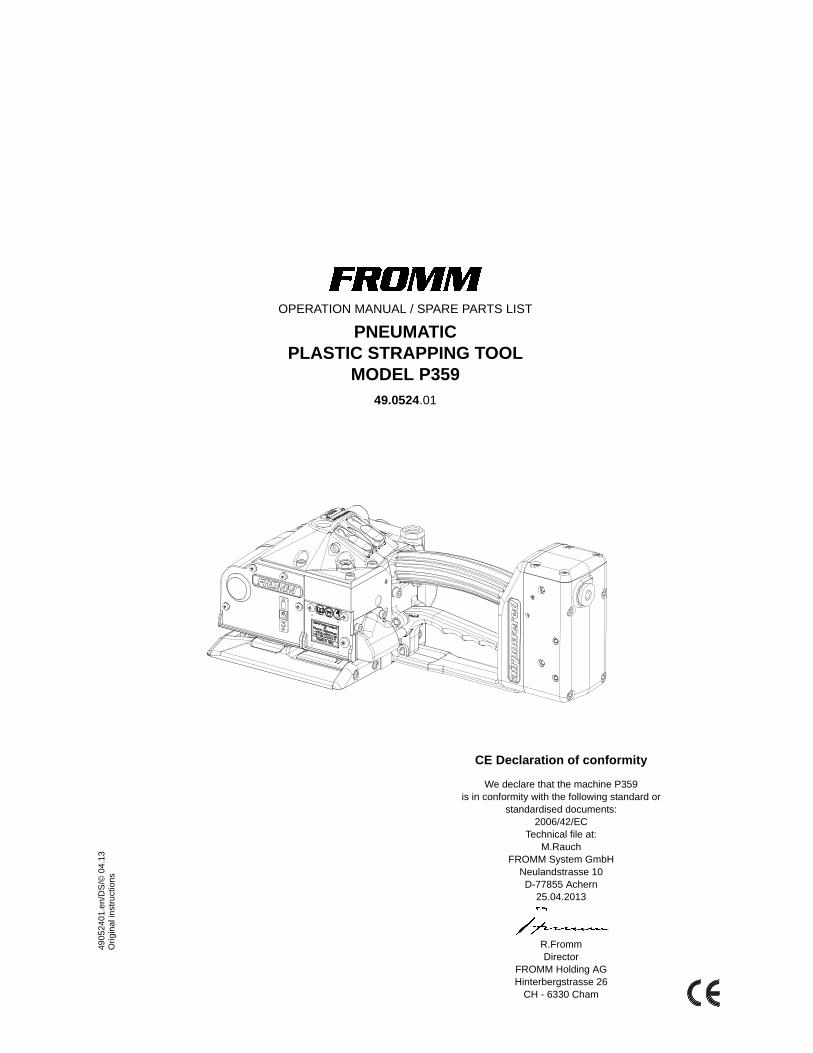
OPERATION MANUAL / SPARE PARTS LIST
PNEUMATIC PLASTIC STRAPPING TOOL
MODEL P359 49.0524.01
CE Declaration of conformity
We declare that the machine P359 is in conformity with the following standard or
standardised documents:2006/42/EC
Technical file at: M.Rauch
FROMM System GmbHNeulandstrasse 10D-77855 Achern
25.04.2013
R.FrommDirector
FROMM Holding AGHinterbergstrasse 26
CH - 6330 Cham
490
524
01
.en
/DS
/© 0
4.1
3O
rig
ina
l in
stru
ctio
ns
7P359mane.fm
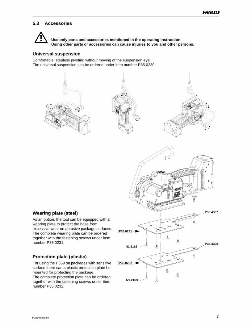
5.3 Accessories
Use only parts and accessories mentioned in the operating instruction. Using other parts or accessories can cause injuries to you and other persons.
Universal suspension Comfortable, stepless pivoting without moving of the suspension eye.The universal suspension can be ordered under item number P35.0230.
Wearing plate (steel)As an option, the tool can be equipped with a wearing plate to protect the base from excessive wear on abrasive package surfaces.The complete wearing plate can be ordered together with the fastening screws under item number P35.0231.
Protection plate (plastic)For using the P359 on packages with sensitive surface there can a plastic protection plate be mounted for protecting the package.The complete protection plate can be ordered together with the fastening screws under item number P35.0232.
P35.4307
N1.2163
P35.0231
P35.0232
P35.4308
N1.2163
13P359mane.fm
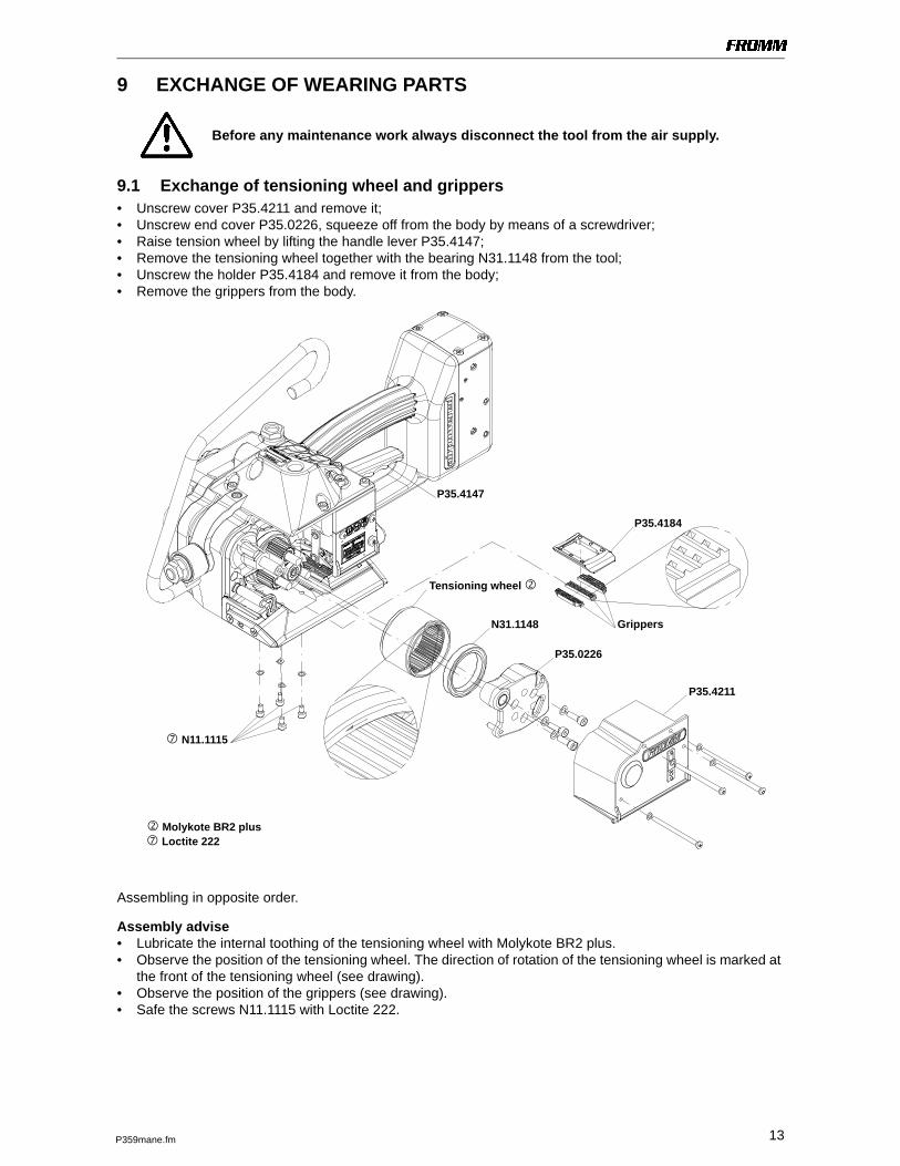
9 EXCHANGE OF WEARING PARTS
Before any maintenance work always disconnect the tool from the air supply.
9.1 Exchange of tensioning wheel and grippers• Unscrew cover P35.4211 and remove it;• Unscrew end cover P35.0226, squeeze off from the body by means of a screwdriver;• Raise tension wheel by lifting the handle lever P35.4147;• Remove the tensioning wheel together with the bearing N31.1148 from the tool;• Unscrew the holder P35.4184 and remove it from the body;• Remove the grippers from the body.
Assembling in opposite order.
Assembly advise• Lubricate the internal toothing of the tensioning wheel with Molykote BR2 plus.• Observe the position of the tensioning wheel. The direction of rotation of the tensioning wheel is marked at
the front of the tensioning wheel (see drawing).• Observe the position of the grippers (see drawing).• Safe the screws N11.1115 with Loctite 222.
Tensioning wheel
P35.4184
Molykote BR2 plus
Grippers
N11.1115
Loctite 222
P35.0226
P35.4211
N31.1148
P35.4147
14 P359mane.fm
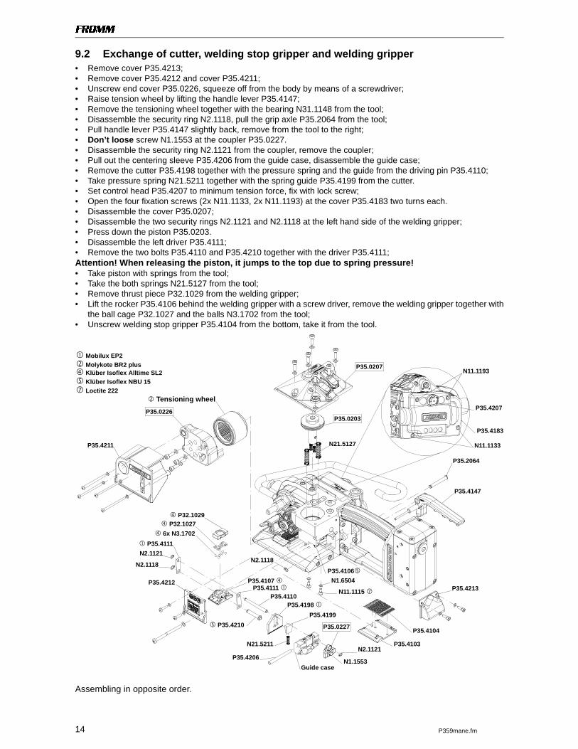
9.2 Exchange of cutter, welding stop gripper and welding gripper• Remove cover P35.4213;• Remove cover P35.4212 and cover P35.4211;• Unscrew end cover P35.0226, squeeze off from the body by means of a screwdriver;• Raise tension wheel by lifting the handle lever P35.4147;• Remove the tensioning wheel together with the bearing N31.1148 from the tool;• Disassemble the security ring N2.1118, pull the grip axle P35.2064 from the tool;• Pull handle lever P35.4147 slightly back, remove from the tool to the right;• Don’t loose screw N1.1553 at the coupler P35.0227.• Disassemble the security ring N2.1121 from the coupler, remove the coupler;• Pull out the centering sleeve P35.4206 from the guide case, disassemble the guide case;• Remove the cutter P35.4198 together with the pressure spring and the guide from the driving pin P35.4110;• Take pressure spring N21.5211 together with the spring guide P35.4199 from the cutter.• Set control head P35.4207 to minimum tension force, fix with lock screw;• Open the four fixation screws (2x N11.1133, 2x N11.1193) at the cover P35.4183 two turns each.• Disassemble the cover P35.0207;• Disassemble the two security rings N2.1121 and N2.1118 at the left hand side of the welding gripper;• Press down the piston P35.0203.• Disassemble the left driver P35.4111;• Remove the two bolts P35.4110 and P35.4210 together with the driver P35.4111;Attention! When releasing the piston, it jumps to the top due to spring pressure!• Take piston with springs from the tool;• Take the both springs N21.5127 from the tool;• Remove thrust piece P32.1029 from the welding gripper;• Lift the rocker P35.4106 behind the welding gripper with a screw driver, remove the welding gripper together with
the ball cage P32.1027 and the balls N3.1702 from the tool;• Unscrew welding stop gripper P35.4104 from the bottom, take it from the tool.
Assembling in opposite order.
P35.4211
P35.4213
Guide case
P35.0227
N2.1118
P35.4106P35.4107
N11.1115
Klüber Isoflex Alltime SL2
Mobilux EP2
Klüber Isoflex NBU 15
Loctite 222
Molykote BR2 plus
P35.4212
P35.4198
N2.1121P35.4103
P35.4104
P35.4110
P35.4199
N1.1553
N11.1193
N11.1133
P35.4207 Tensioning wheel
P32.1029
P32.1027
6x N3.1702
P35.4111
N2.1118
N2.1121
N21.5211
P35.4206
P35.0226
P35.0207
N1.6504
P35.4183
P35.2064
P35.4147
P35.4210
P35.4111
P35.0203
N21.5127
15P359mane.fm
Assembly advise• When inserting the piston pay attention to the proper seat of the piston in the thrust piece.• Pay attention to the fitting position of the cutter (see drawing).• Safe the screws N11.1115 with Loctite 222.• Lubricate the rocker and the bolt P35.4210 in the area of the welding jaw with Klüber Isoflex NBU 15.• Lubricate the balls, ball cage and the running surface of the balls on the welding gripper with Klüber Isoflex
Alltime SL2.• Lubricate the cutter and the driver with Mobilux EP2.
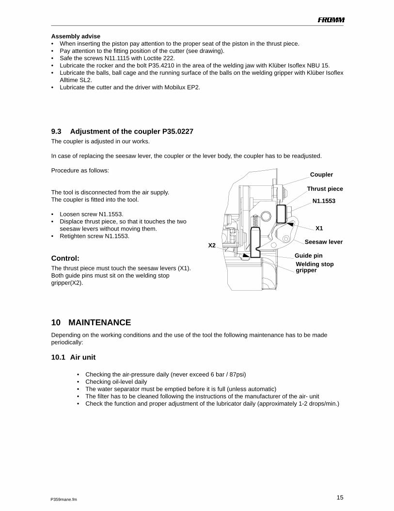
9.3 Adjustment of the coupler P35.0227The coupler is adjusted in our works.
In case of replacing the seesaw lever, the coupler or the lever body, the coupler has to be readjusted.
Procedure as follows:
The tool is disconnected from the air supply.The coupler is fitted into the tool.
• Loosen screw N1.1553.• Displace thrust piece, so that it touches the two
seesaw levers without moving them.• Retighten screw N1.1553.
Control:The thrust piece must touch the seesaw levers (X1).Both guide pins must sit on the welding stop gripper(X2).
10 MAINTENANCEDepending on the working conditions and the use of the tool the following maintenance has to be made periodically:
10.1 Air unit
• Checking the air-pressure daily (never exceed 6 bar / 87psi)• Checking oil-level daily• The water separator must be emptied before it is full (unless automatic)• The filter has to be cleaned following the instructions of the manufacturer of the air- unit• Check the function and proper adjustment of the lubricator daily (approximately 1-2 drops/min.)
Coupler
Thrust piece
N1.1553
Seesaw lever
Welding stop
X1
X2
Guide pin
gripper
17
49
052
40
1.z
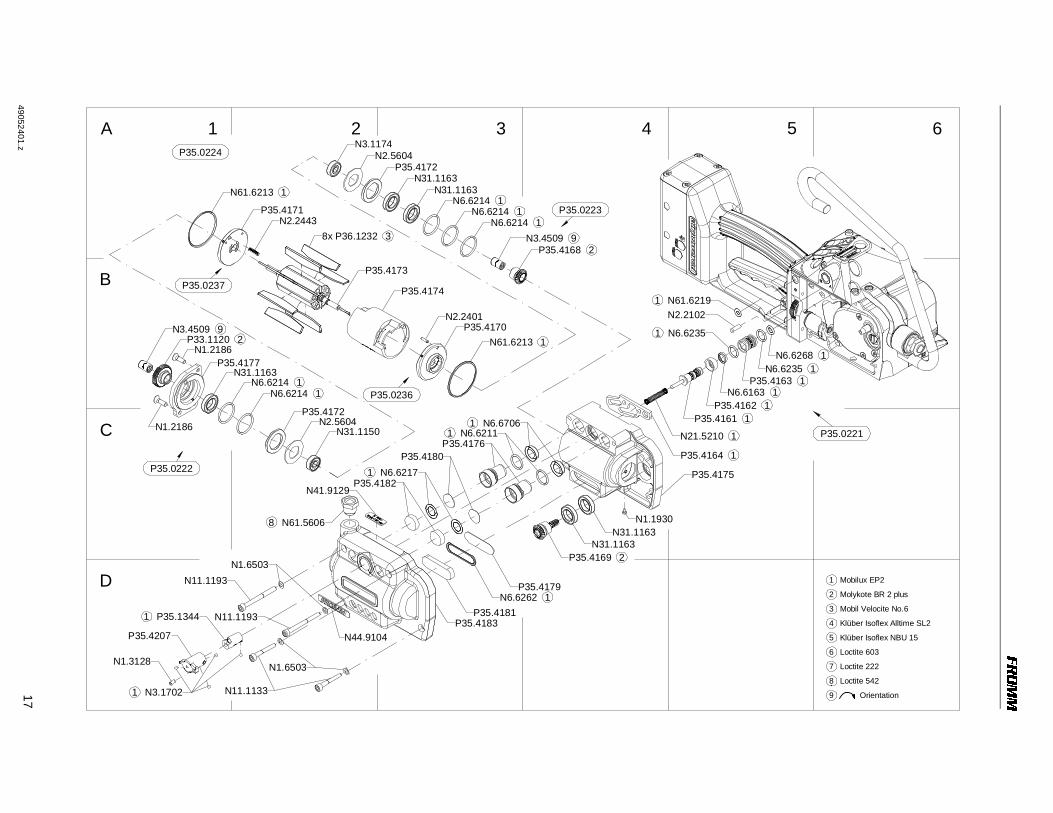
A 1
B
C
2 3 4 5 6
D2P35.4169
N1.1930
1N6.6262P35.4179
1 N6.67061 N6.6211
P35.4176P35.4180
1 N6.6217P35.4182
N3.1174N2.5604
P35.4172
1N6.6214
N31.1163
1N6.62141N6.6214
N31.1163
9N3.45092P35.4168
1N61.6213
P35.4171N2.2443
P35.4174
N2.2401P35.41709N3.4509
N1.21862P33.1120
P35.4177N31.1163
1N6.62141N6.6214
P35.4172N2.5604N1.2186
8 N61.5606
N11.1193N1.6503
N11.1193
N1.6503
1 N3.1702
N1.3128
P35.4207
1 P35.1344
N11.1133
N2.2102
1N6.62351N6.6268
1N21.5210
N31.1163
P35.4181
N31.1163
P35.0224
P35.0223
P35.0221
P35.0222
P35.4183
P35.4175
38x P36.1232
1N61.6213
P35.4173P35.0237
P35.0236
N31.1150
N44.9104
N41.9129
1P35.41631N6.6163
1 N61.6219
1P35.4162
1 N6.6235
1P35.4161
1P35.4164
7 Loctite 222
6 Loctite 603
5 Klüber Isoflex NBU 15
4 Klüber Isoflex Alltime SL2
3 Mobil Velocite No.6
2 Molykote BR 2 plus
1 Mobilux EP2
9 Orientation
8 Loctite 542
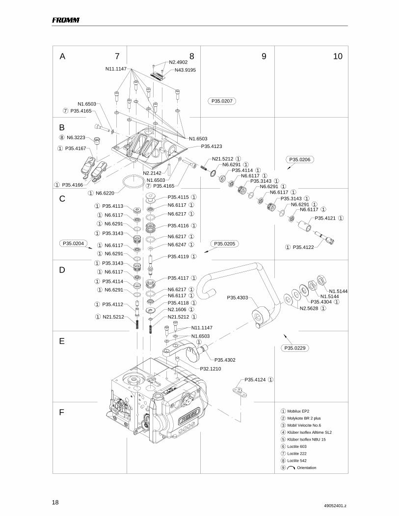
1849052401.z
A 7
B
C
F
8 9 10
E
D
1 N21.5212
1 P35.4112
1 N6.6291
1 P35.4114
1 N6.6291
1 N6.6117
1 P35.3143
1 N6.6291
1 N6.6117
1 P35.4113
1N21.52121N2.16061P35.4118
1N6.61171N6.6217
1P35.4117
1N6.62471N6.6217
1P35.4116
1N6.6217
1N6.61171P35.4115
8 N6.3223
1 P35.4166
N1.6503
N2.4902N43.9195
1N21.52121N6.6291
1N6.6291
1P35.31431N6.6291
1N6.6117
1P35.4121
1P35.4114
1P35.3143N1.65037 P35.4165
N2.2142
1P35.4304N1.5144
N1.5144
1N2.5628
P35.4302
N11.1147
N1.6503
P32.1210
1 N6.6220
N1.6503P35.4123
N11.1147
7 P35.4165
P35.4303
1 P35.31431P35.4119
1 P35.4167
1P35.4124
1 P35.4122
P35.0207
P35.0206
P35.0205P35.0204
P35.0229
1 N6.6117
1N6.6117
1N6.6117
1
7 Loctite 222
6 Loctite 603
5 Klüber Isoflex NBU 15
4 Klüber Isoflex Alltime SL2
3 Mobil Velocite No.6
2 Molykote BR 2 plus
1 Mobilux EP2
9 Orientation
8 Loctite 542
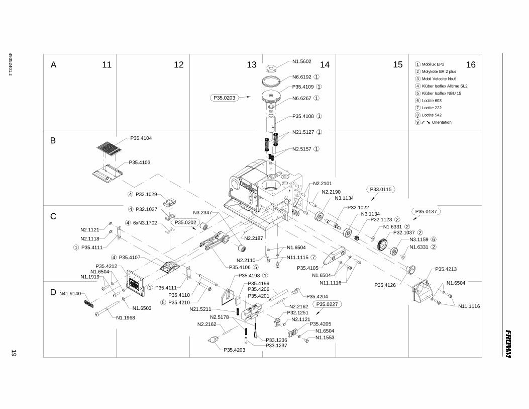
19
49
052
40
1.z
A 11
B
C
12 13 14 15 16
D
N1.1919
N1.1968
N1.6503
N1.6504
P35.4206P35.4204
P35.4205N1.6504N1.1553P33.1236
P33.1237
N2.5178N21.5211
N1.6504
5 P35.4210
4 P35.4107 7N11.1115
N11.1116N1.6504
N3.2347
N1.5602
1N6.6192
1N6.6267
1P35.4108
1N21.5127
1N2.5157
N1.6504
P35.4213
P35.0203
P35.4104
P35.4103
N41.9140
P35.4212
N2.1118
4 P32.1027
4 6xN3.1702
4 P32.1029
N2.2162P32.1251
N2.1121N2.2162
P35.4110
5P35.4106
N2.2187
P35.41991P35.4198
N2.2110P35.4105
N2.2190
N2.2101
N3.1134
P32.1022N3.1134
2P32.11232N1.6331
2P32.10376N3.11592N1.6331
P35.4126
N11.1116
P33.0115
P35.0137
P35.0227
P35.0202
1 P35.4111
N2.1121
P35.4201
1P35.4109
P35.4203
1 P35.4111
7 Loctite 222
6 Loctite 603
5 Klüber Isoflex NBU 15
4 Klüber Isoflex Alltime SL2
3 Mobil Velocite No.6
2 Molykote BR 2 plus
1 Mobilux EP2
9 Orientation
8 Loctite 542
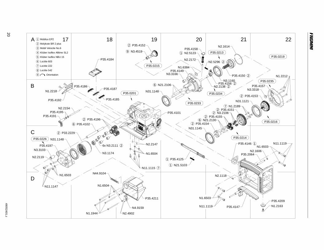
2049
05
240
1.z
A 17
B
C
18 19 20 21 22
D
9 N3.4519
2 P35.4152P35.4158
1 N2.5123
N2.2172
2P35.4150
2N2.2138
2N2.5296
N1.6384P35.4149
N3.3166
6 N21.2106
N31.1148
N31.11452 P35.4154
6 N21.21302 P35.4155
2 N3.21062 P35.4151
7 N1.2189N31.1121
2 P35.4153
N3.3318P35.4157
N1.2212
1P35.4146 N11.1119
P35.4209N1.2163P35.4147N11.1119
N1.6503
1 N21.5103
N1.6504
N4.9159
N2.4902
N44.9104
N1.1944
P35.4211
7N11.1115
N1.6504
N2.2147
N2.1118
N3.1174
6 P35.4102
2 P33.2229
N31.1148
P35.4197N3.3103
N2.2119
N1.6503
N11.1147
N2.2154P35.4195
P35.4191
P35.4192
P35.4184
P35.4186P35.4187
P35.4185
2P35.4156
2 P35.4196
26x N3.2111
1 P35.4125
N1.2218
P35.0235
P35.0216
P35.0214
P35.0219P35.0213
P35.0215
P35.0201
P35.0226
N1.6503
P35.2064N2.1606
P35.0234
P35.4101
N2.1614
P35.0233
N3.1160
7 Loctite 222
6 Loctite 603
5 Klüber Isoflex NBU 15
4 Klüber Isoflex Alltime SL2
3 Mobil Velocite No.6
2 Molykote BR 2 plus
1 Mobilux EP2
9 Orientation
8 Loctite 542
2149052401.z
A 23
B
C
F
24 25 26
E
D
N1.1813
P35.4129
1 N6.6255
1N6.62671N6.6267
1P35.1318
1N6.6267
P35.13171N6.62471P35.1350
1N6.6267
1 P35.4144
1 N6.6255
1 N21.5209
1 N6.6120
1 N6.6255
1 P35.41391 N6.6255
1 N6.6123
1 P35.41411 N6.62551 N6.6123
1 P35.4139
1 N6.62551 N6.6123
1 P35.41401 N6.62551 N6.6123
1 P35.4138
1 N2.5232
1 P35.4131
1 N2.1601
1 N6.6255
1 P35.4134
1 N6.6123
1 P35.41351 N6.62551 N6.6123
1 P35.41361 N6.62551 N6.6117
1 P35.41371 N6.62551 N6.6117
1 P35.41331 N6.62551 N6.6117
1 P35.41331 N6.6255
1 N6.61171 P35.4132
1 P35.4130
1 N61.6208
N6.6157P35.2058
P36.13051 N61.6208
P36.1306N4.5137
P35.4128N2.2101
1N6.6283
P36.1306N2.1301
1N6.6283
1N61.6208P36.1305
P35.2058
P35.41451N61.6208
N4.5137
N11.1193
N1.6503
N11.1193
N21.5213
N6.6157
P35.2060
N1.6503
N6.5136
1 N6.6123
1 P35.4142
1 P35.4143
P35.0209
P35.0208
P35.0210
P35.0211
P35.0211P35.0212
P35.4127
N21.5213
P35.4145
N2.1301
P35.2060
7 Loctite 222
6 Loctite 603
5 Klüber Isoflex NBU 15
4 Klüber Isoflex Alltime SL2
3 Mobil Velocite No.6
2 Molykote BR 2 plus
1 Mobilux EP2
9 Orientation
8 Loctite 542
[ ] = Group * = Wearing parts
22 49052401.een.fm
13 SPARE PARTS LIST 49.0524.01
49.0524.01 P359/32/0.80-1.35/7.0 P359.0001.01 13.03.13
Item-No. in group Pcs. Description Dimension Field
N1.1553 P35.0227 1 HEXAGON SCREW M4 X 8 D14
N1.1813 P35.0212 4 RAISED CTRS. HEAD SCREW M5 X 16 B25
N1.1919 2 SCREW M4 X 16 C11
N1.1930 P35.0224 1 FLAT HEAD SCREW M3 X 4 C4
N1.1944 4 SCREW M4 X 60 D18
N1.1968 1 SCREW M5 X 70 D12
N1.2163 1 COUNTERSUNK SCREW M5 X 12 D22
N1.2186 P35.0224 2 COUNTERSUNK SCREW M5 X 16 B1+
N1.2189 P35.0214 3 COUNTERSUNK SCREW M4 X 20 B21
N1.2212 P35.0219 4 COUNTERSUNK SCREW M4 X 25 A22
N1.2218 2 COUNTERSUNK SCREW M4 X 12 B17
N1.3128 1 SOCKET SET SCREW M4 X 8 D1
N1.5144 P35.0229 2 HEXAGON NUT M12 X 1.25 D10
[N1.5602] P35.0203 1 SLOTTED ROUND NUT M10 X 1 A14
N1.6331 2 SPACER WASHER 6 X 12 X 0.5 C15+
N1.6384 P35.0219 1 SPACER WASHER 11 X 17 X 0.5 A20
N1.6503 20 SAFETY WASHER M5 D2+
N1.6503 P35.0207 2 SAFETY WASHER M5 A7+
N1.6503 P35.0212 4 SAFETY WASHER M5 D24
N1.6504 16 SAFETY WASHER M4 C11+
N1.6504 P35.0227 1 SAFETY WASHER M4 D14
N11.1115 6 SCREW M4 X 8 C14+
N11.1116 4 SCREW M4 X 12 C14+
N11.1119 4 SCREW M5 X 20 D21+
N11.1133 2 SCREW M5 X 35 D2
N11.1147 11 SCREW M5 X 16 A7+
N11.1193 2 FLAT HEAD SCREW M5 X 55 D1+
N11.1193 P35.0212 4 FLAT HEAD SCREW M5 X 55 D23
N2.1118 2 SECURITY RING 6 C11+
N2.1121 2 SECURITY RING 5 C11+
N2.1301 P35.0211 1 CIRCLIP 6 E23+
N2.1601 P35.0208 1 SPRING RING SW12 D24
N2.1606 1 SPRING RING SW6 C22
N2.1606 P35.0205 1 SPRING RING SW6 D8
N2.1614 P35.0219 1 SPRING RING A21
N2.2101 2 PARALLEL PIN 5 m6 X 12 B14
N2.2101 P35.0212 1 PARALLEL PIN 5 m6 X 12 E25
N2.2102 1 PARALLEL PIN 5 m6 X 16 B5
N2.2110 P35.0201 1 PARALLEL PIN 4 m6 X 10 C13
N2.2119 P35.0226 1 PARALLEL PIN 4 m6 X 18 C17
N2.2138 P35.0234 1 PARALLEL PIN 4 m6 X 12 B21
N2.2142 P35.0207 1 PARALLEL PIN 4 m6 X 28 B8
N2.2147 P35.0201 2 PARALLEL PIN 3 m6 X 10 C19
N2.2154 1 PARALLEL PIN 5 h6 X 60 B17
N2.2162 2 PARALLEL PIN 3 m6 X 24 D13+
N2.2172 P35.0233 1 PARALLEL PIN 5 m6 X 30 A20
N2.2187 P35.0201 1 PARALLEL PIN 3 m6 X 6 C13
N2.2190 1 PARALLEL PIN 6 h6 X 18 B14
N2.2401 P35.0236 1 DOWEL PIN 3 X 10 B3
N2.2443 P35.0237 1 DOWEL PIN 4 X 15 A2
N2.4902 4 HAMMER HEAD BOLT 1.85 X 4.76 A8+
[ ] = Group * = Wearing parts
23
N2.5123 1 PRESSURE SPRING 1 X 8 X 40/12.5 A20
N2.5157 2 PRESSURE SPRING 0.6 X 4.8 X 20/15.5 B14
N2.5178 2 PRESSURE SPRING 0.32X2.82X20.5/20.5 D13
N2.5232 P35.0208 1 PRESSURE SPRING 0.80X7.80X39.0/10.5 D24
N2.5296 P35.0219 1 PRESSURE SPRING 0.5 X 4 X 24/16.5 A21
N2.5604 P35.0224 2 CUP SPRING 31.5 X 16.3 X 1.25 A3+
N2.5628 P35.0229 2 CUP SPRING 25 X 12.2 X 1/1.8 D10
N21.2106 P35.0233 3 PARALLEL PIN 8 h6 X 50 B20
N21.2130 P35.0214 3 PARALLEL PIN 5 h6 X 20 B21
N21.5103 1 PRESSURE SPRING 0.5 X 4 X 31/21.5 C20
N21.5127 2 PRESSURE SPRING 1.1 X 9.0 X 50/14.5 B14
N21.5209 P35.0209 1 PRESSURE SPRING 0.7 X 7.5 X 35.8/11.5 C24
N21.5210 1 PRESSURE SPRING 0.8 X 6.1 X 46/17.5 C5
N21.5211 1 PRESSURE SPRING 0.75 X 4.5 X 24/15.5 D13
N21.5212 P35.0204 1 PRESSURE SPRING 0.5 X 3.7 X 26.5/18.5 D7
N21.5212 P35.0205 1 PRESSURE SPRING 0.5 X 3.7 X 26.5/18.5 D8
N21.5212 P35.0206 1 PRESSURE SPRING 0.5 X 3.7 X 26.5/18.5 B9
N21.5213 P35.0211 1 PRESSURE SPRING 0.32 X 8.5 X 17/6.5 E24+
N3.1134 1 BALL BEARING 7 X 22 X7 B15
N3.1134 P33.0115 1 BALL BEARING 7 X 22 X7 C15
N3.1159 P35.0137 1 BALL BEARING 6 X 19 X 6 C16
N3.1160 P35.0213 1 BALL BEARING 40 X 52 X 7 B21
N3.1174 1 BALL BEARING 7 X 19 X 6 C18
N3.1174 P35.0224 1 BALL BEARING 7 X 19 X 6 A2
N3.1702 10 BALL 4 MM D1+
N3.2106 P35.0214 3 NEEDLE CAGE K 5 X 8 X 10 TN B21
N3.2111 6 NEEDLE CAGE K 8 X 11 X 10 TV C18
N3.2347 P35.0202 2 NEEDLE BUSH 10 X 14 X 12 C13
N3.3103 P35.0226 1 SLIDE-BEARING 10 X 12 X 20 C17
N3.3166 P35.0233 1 SLIDE-BEARING 10 X 12 X 12 A20
N3.3318 P35.0235 1 SLIDE-BEARING 8 X 10 X 4 B22
N3.4509 P35.0222 1 NEEDLE FREE WHEELING 6 X 10 X 15 B1
N3.4509 P35.0223 1 NEEDLE FREE WHEELING 6 X 10 X 15 A4
N3.4519 P35.0215 1 FREE-WHEELING 8 X 12 X 22 A19
N31.1121 P35.0216 1 BALL BEARING 45 X 58 X 7 B21
N31.1145 P35.0214 1 BALL BEARING 45 X 55 X 6 C20
N31.1148 2 BALL BEARING 40 X 52 X 7 C17+
N31.1150 P35.0224 1 BALL BEARING 8 X 19 X 6 C2
N31.1163 P35.0222 1 BALL BEARING 15 X 24 X 5 B2
N31.1163 P35.0224 4 BALL BEARING 15 X 24 X 5 A3+
N4.5137 2 PROTECTING CAP E23+
N4.9159 1 LABEL <<CE>> D19
N41.9129 1 ADHESIVE LABEL p max. 6 bar/87 psi C2
N41.9140 1 ADHESIVE LABEL 30 X 10 X 0.1 D11
N43.9195 1 TYPE PLATE <<P359>> A8
N44.9104 2 ADHESIVE LABEL <<FROMM>> D2+
N6.3223 P35.0207 1 PRESSURE READING B7
N6.5136 P35.0212 1 SEALING SCREW D24
N6.6117 P35.0204 3 SEAL 6 X 13 X 2.3 C7+
N6.6117 P35.0205 2 SEAL 6 X 13 X 2.3 C8+
N6.6117 P35.0206 3 SEAL 6 X 13 X 2.3 B9+
N6.6117 P35.0208 4 SEAL 6 X 13 X 2.3 A24+
N6.6120 P35.0209 1 SEAL 16 X 9 X 2.3 C24
49.0524.01 P359/32/0.80-1.35/7.0 P359.0001.01 13.03.13
Item-No. in group Pcs. Description Dimension Field
[ ] = Group * = Wearing parts
24 49052401.een.fm
N6.6123 P35.0208 2 SEAL 12 X 19 X 2.3 C24
N6.6123 P35.0209 5 SEAL 12 X 19 X 2.3 A24+
N6.6157 P35.0211 1 PACKING RING 4 MM E24+
N6.6163 P35.0221 1 SEAL 10 X 13.6 X 2.3 B5
N6.6192 P35.0203 1 SEAL 45 X 36 X 2.8 A14
N6.6211 P35.0224 2 O-RING 16 X 2 C3
N6.6214 P35.0222 2 O-RING 23 X 2 B2
N6.6214 P35.0224 3 O-RING 23 X 2 A3
N6.6217 2 O-RING 15 X 2 C3
N6.6217 P35.0205 3 O-RING 15 X 2 C8+
N6.6220 P35.0207 1 O-RING 40 X 2.5 C7
N6.6235 P35.0221 2 O-RING 12 X 2 B5
N6.6247 P35.0205 1 O-RING 5 X 2.5 C8
N6.6247 P35.0210 1 O-RING 5 X 2.5 D25
N6.6255 P35.0208 6 O-RING 21 X 2 B24+
N6.6255 P35.0209 6 O-RING 21 X 2 A24+
N6.6255 P35.0212 1 O-RING 21 X 2 C25
N6.6262 1 O-RING 32 X 2.0 D3
N6.6267 P35.0203 1 O-RING 10 X 2.0 A14
N6.6267 P35.0210 3 O-RING 10 X 2.0 C25+
N6.6267 P35.0212 1 O-RING 10 X 2.0 C25
N6.6268 P35.0221 1 O-RING 6 X 2.5 B5
N6.6283 P35.0211 1 O-RING 4 X 1 E24+
N6.6291 P35.0204 3 O-RING 11.5 X 1.5 C7+
N6.6291 P35.0206 3 O-RING 11.5 X 1.5 B9+
N6.6706 P35.0224 2 DIAPHRAGM C3
N61.5606 1 REDUCING COUPLING C2
N61.6208 P35.0211 2 O-RING 9.5 X 1.5 E24+
N61.6213 P35.0224 2 O-RING 45 X 1.5 A2+
N61.6219 1 O-RING 7 X 2 B5
P32.1022 P33.0115 1 WELDING EXCENTRIC C15
P32.1027 1 BALL CAGE C12
[P32.1029] 1 THRUST PIECE B12
P32.1037 P35.0137 1 GEAR WHEEL C15
P32.1123 P33.0115 1 PINION C15
P32.1210 1 CENTERING SLEEVE E9
[P32.1251] P35.0227 1 PUSHER D14
[P33.0115] 1 WELDING EXCENTRIC B15
P33.1120 P35.0222 1 GEAR WHEEL B1
P33.1236 1 GUIDE PIN D14
P33.1237 1 GUIDE PIN D14
[P33.2229] * 1 TENSIONING WHEEL C17
[P35.0137] 1 GEAR WHEEL C16
[P35.0201] 1 BODY B19
[P35.0202] 1 ROCKER C12
[P35.0203] 1 PISTON A13
[P35.0204] 1 VALVE C7
[P35.0205] 1 VALVE C9
[P35.0206] P35.0207 1 VALVE B10
[P35.0207] 1 COVER A9
[P35.0208] P35.0212 1 VALVE A25
[P35.0209] P35.0212 1 VALVE A24
[P35.0210] P35.0212 1 SHUTTLE VALVE C25
49.0524.01 P359/32/0.80-1.35/7.0 P359.0001.01 13.03.13
Item-No. in group Pcs. Description Dimension Field
[ ] = Group * = Wearing parts
25
[P35.0211] P35.0212 2 THROTTLE E23+
[P35.0212] 1 HANDLE F25
[P35.0213] P35.0219 1 GEAR WHEEL A21
[P35.0214] P35.0219 1 WHEEL C21
[P35.0215] P35.0219 1 RATCHET WHEEL A19
[P35.0216] P35.0219 1 GEAR WHEEL B22
[P35.0219] 1 GEAR A22
[P35.0221] 1 VALVE C6
[P35.0222] P35.0224 1 GEAR WHEEL C1
[P35.0223] P35.0224 1 CONICAL GEAR WHEEL A4
[P35.0224] 1 AIR MOTOR A1
[P35.0226] 1 END COVER C17
[P35.0227] 1 PUSHER D14
[P35.0229] 1 SUSPENSION E10
[P35.0233] P35.0219 1 GEAR BODY B20
[P35.0234] P35.0219 1 LEVER B21
[P35.0235] P35.0219 1 GEARING COVER B22
[P35.0236] P35.0224 1 END PLATE B3
[P35.0237] P35.0224 1 END PLATE B1
P35.1317 P35.0210 1 VALVE STEM D25
P35.1318 P35.0210 1 VALVE SHELL D25
P35.1344 1 SLIDE GATE D1
P35.1350 P35.0210 1 COUNTER SLEEVE D25
P35.2058 P35.0211 1 THROTTLE BODY E24+
P35.2060 P35.0211 1 THROTTLE SCREW F24
P35.2064 1 HANDLE SHAFT C21
P35.3143 P35.0204 2 SUSTAINING RING C7+
P35.3143 P35.0206 2 SUSTAINING RING B9+
[P35.4101] P35.0201 1 BODY B20
P35.4102 P35.0201 1 BOLT B18
[P35.4103] 1 STEEL INSERT B12
P35.4104 * 1 WELDING STOP GRIPPER B12
[P35.4105] 1 STRAP GUIDE PLATE C14
[P35.4106] P35.0202 1 ROCKER C13
[P35.4107] * 1 WELDING GRIPPER C12
P35.4108 P35.0203 1 PISTON ROD A14
P35.4109 P35.0203 1 PISTON PLATE A14
P35.4110 1 DRIVING PIN D12
[P35.4111] 2 DRIVER C11+
P35.4112 P35.0204 1 PUSHER D7
P35.4113 P35.0204 1 EXHAUST RING C7
P35.4114 P35.0204 1 GUIDE D7
P35.4114 P35.0206 1 GUIDE B9
P35.4115 P35.0205 1 VALVE RING C8
P35.4116 P35.0205 1 SUSTAINING RING C8
P35.4117 P35.0205 1 SUSTAINING RING D8
P35.4118 P35.0205 1 DISK D8
P35.4119 P35.0205 1 PUSHER C8
P35.4121 P35.0206 1 DOWEL C10
P35.4122 P35.0206 1 SLIDE BOLT C10
[P35.4123] P35.0207 1 COVER B9
P35.4124 1 SEAL PLATE E9
[P35.4125] 1 PUSHER C20
49.0524.01 P359/32/0.80-1.35/7.0 P359.0001.01 13.03.13
Item-No. in group Pcs. Description Dimension Field
[ ] = Group * = Wearing parts
26 49052401.een.fm
P35.4126 1 BEARING SUPPORT D15
[P35.4127] P35.0212 1 HANDLE F25
[P35.4128] P35.0212 1 VALVE HOUSING E25
[P35.4129] P35.0212 1 COVER C26
P35.4130 P35.0212 1 SEAL PLATE E25
P35.4131 P35.0208 1 VALVE STEM D24
P35.4132 P35.0208 1 INTERMEDIATE RING A24
P35.4133 P35.0208 2 SUSTAINING RING B24
P35.4134 P35.0208 1 END RING C24
P35.4135 P35.0208 1 SUSTAINING RING C24
P35.4136 P35.0208 1 SUSTAINING RING C24
P35.4137 P35.0208 1 SUSTAINING RING B24
P35.4138 P35.0209 1 END RING A24
P35.4139 P35.0209 2 SUSTAINING RING B24
P35.4140 P35.0209 1 SUSTAINING RING A24
P35.4141 P35.0209 1 SUSTAINING RING B24
P35.4142 P35.0209 1 INTERMEDIATE RING C24
P35.4143 P35.0209 1 VALVE STEM C24
P35.4144 P35.0209 1 CYLINDER D24
P35.4145 P35.0211 1 THROTTLE SEAT E24+
P35.4146 1 SEAL PLATE C21
[P35.4147] 1 HANDLE LEVER D21
[P35.4149] P35.0233 1 GEAR BODY A20
P35.4150 P35.0213 1 GEAR WHEEL A21
P35.4151 P35.0214 1 GEAR WHEEL B21
P35.4152 P35.0215 1 GEAR WHEEL A19
P35.4153 P35.0216 1 GEAR WHEEL B22
P35.4154 P35.0214 1 PLANET SHAFT B20
P35.4155 P35.0214 3 PINION B21
[P35.4156] P35.0234 1 LEVER B21
[P35.4157] P35.0235 1 GEARING COVER B22
[P35.4158] 1 ROCKER A20
[P35.4161] P35.0221 1 CONTROL ROD C5
P35.4162 P35.0221 1 END RING B5
P35.4163 P35.0221 1 VALVE SHELL B5
P35.4164 1 SEAL PLATE C5
[P35.4165] P35.0207 2 SHAFT A7+
[P35.4166] P35.0207 1 LEVER B7
[P35.4167] P35.0207 1 LEVER B7
P35.4168 P35.0223 1 CONICAL GEAR WHEEL A4
P35.4169 P35.0224 1 CONICAL GEAR WHEEL C4
P35.4170 P35.0236 1 END PLATE B3
P35.4171 P35.0237 1 END PLATE A2
P35.4172 P35.0224 2 SUPPORTING DISK C2+
P35.4173 P35.0224 1 ROTOR B3
P35.4174 P35.0224 1 JACKET B3
[P35.4175] P35.0224 1 MOTOR HOUSING C5
P35.4176 P35.0224 2 RETAINER C3
P35.4177 P35.0222 1 COVER B2
P35.4179 1 SIEVE D4
P35.4180 2 SIEVE C3
P35.4181 1 EXHAUST SILENCER D3
P35.4182 2 EXHAUST SILENCER C2
49.0524.01 P359/32/0.80-1.35/7.0 P359.0001.01 13.03.13
Item-No. in group Pcs. Description Dimension Field
[ ] = Group * = Wearing parts
27
[P35.4183] 1 COVER D3
[P35.4184] 1 HOLDER A18
[P35.4185] * 1 GRIPPER B18
[P35.4186] * 1 GRIPPER B18
[P35.4187] * 1 GRIPPER B18
[P35.4191] 1 STRAP STOP B17
[P35.4192] 1 STRAP STOP B17
P35.4195 2 SPACER WASHER B17
P35.4196 3 PINION B18
[P35.4197] P35.0226 1 END COVER C17
[P35.4198] * 1 CUTTER C13
P35.4199 1 GUIDE D13
[P35.4201] 1 GUIDE CASE D13
[P35.4203] 1 SEESAW LEVER D13
[P35.4204] 1 SEESAW LEVER D14
[P35.4205] P35.0227 1 THRUST PIECE D14
P35.4206 1 CENTERING SLEEVE D13
P35.4207 1 CONTROL HEAD D1
P35.4209 1 DISK D22
[P35.4210] 1 BOLT D12
P35.4211 1 COVER D19
P35.4212 1 COVER C11
P35.4213 1 COVER C16
[P35.4302] P35.0229 1 RETAINER E9
[P35.4303] P35.0229 1 SUSPENSION BRACKET D9
P35.4304 P35.0229 1 DISK D10
P36.1232 * P35.0224 8 VANE A2
P36.1305 P35.0211 1 GUIDE E24+
P36.1306 P35.0211 1 THROTTLE HOLDER E23+
49.0524.01 P359/32/0.80-1.35/7.0 P359.0001.01 13.03.13
Item-No. in group Pcs. Description Dimension Field