Embed Size (px)
Citation preview

OPERATION MANUAL Ver 1.0
www.hitecrcd.com
OPERATION MANUAL Ver 1.0
INTRODUCTIONWarnings and Safety Instructions ................................................................................................................................3
P51D MUSTANGFeatures and Speci� cations ...........................................................................................................................................4Items Required to Ready This Model for Flight .......................................................................................................4Parts Layout and Listing ..................................................................................................................................................4Assembly Instructions ......................................................................................................................................................5Spare Parts ............................................................................................................................................................................6
F4U CORSAIRFeatures and Speci� cations ...........................................................................................................................................7Items Required to Ready This Model for Flight .......................................................................................................7Parts Layout and Listing ..................................................................................................................................................7Assembly Instructions ......................................................................................................................................................8Spare Parts ......................................................................................................................................................................... 10
HAWKER HURRICANE MKIIBFeatures and Speci� cations ........................................................................................................................................ 11Items Required to Ready This Model for Flight .................................................................................................... 11Parts Layout and Listing ............................................................................................................................................... 11Assembly Instructions ................................................................................................................................................... 12Spare Parts ......................................................................................................................................................................... 13
PREPARING FOR FLIGHTSpeed Control Operation ............................................................................................................................................ 14centering Control surfaces .......................................................................................................................................... 14Flying Your Plane ............................................................................................................................................................. 14
TABLE OF CONTENTS
SERVICE AND SUPPORT ................................................................................................................................................. 15
WARRANTY ........................................................................................................................................................................... 15
- 2 -
Thank you for purchasing a radio controlled warbird model from Weekender by Hitec. Featuring assembled airframes with pre-installed servos, brushless motors and e� cient speed controls, these sporty military classics assemble within minutes to provide high adrenaline excitement for all beginner to intermediate pilots. Each has four channel control for ailerons, elevator, throttle and rudder and a realistic military paint scheme that will have you harkening back to the glory days of World War II. Fly the Adventure!
Weekender Warbirds are radio control model planes designed for novice pilots over the age of 14. Improper assembly or user negligence can lead to serious injury and/or property damage to yourself or other persons. Weekender is not responsible for any damages or injuries caused by the user’s negligence or improper assem-bly of the model. Be sure to read the instruction manual thoroughly before assembly and � ying.
Safety is of the utmost importance when � ying any model aircraft. Third party insurance is mandatory. If you join a model club or association, suitable coverage will usually be available through the organization. It is your personal responsibility to ensure that your insurance is adequate (i.e. that its coverage includes pow-ered model aircraft). Always � y in such a way that you do not endanger yourself or others. Bear in mind that even the best RC systems are subject to outside interference. No matter how many years of accident-free � ying you have, there is always the possibility of an unforeseen problem or error that can cause an accident. Make it your job to keep your models and your radio control system in perfect operating condition at all times. Check and observe the correct charging procedure for the batteries you are using. Before every � ight, check that the wings and the tail panels are attached and � rmly seated. Also check to make sure that each control surface is operating correctly.
Flying Your Aircraft
• You should only � y at an o� cial model air� eld.• Check that other pilots and spectators are positioned safely before � ying your model.• Wait for other pilots to land their models if they are � ying already.• Do not � y the plane behind yourself or others.• Do not � y under the in� uence of alcohol or drugs or if you are feeling ill.• Do not � y during thunderstorms or high wind. • Do not � y in an area where people are gathered or near tall buildings.• Do not � y near streets or where vehicles or trains pass by.• Do not � y near explosive materials.• Do not � y near power lines or transmission towers.• Be sure to do pre-� ight safety checks of the model before � ying.• Always remember that the pilot is responsible for any outcome that may occur during the � ight.
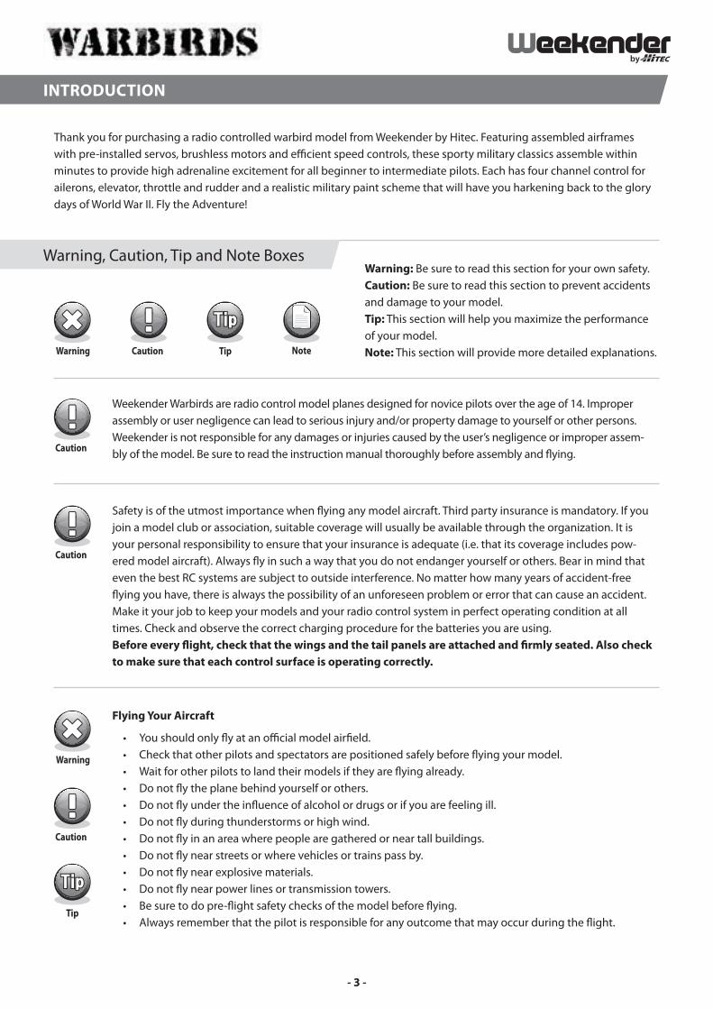
Warning: Be sure to read this section for your own safety. Caution: Be sure to read this section to prevent accidents and damage to your model.Tip: This section will help you maximize the performance of your model. Note: This section will provide more detailed explanations.
Warning, Caution, Tip and Note Boxes
INTRODUCTION
- 3 -
P51D MUSTANG
The P51D Mustang is a Plug and Play (P2GO) type model that requires additional items for operation. The items listed below are needed to � y.
• 4-Channel Radio and Receiver
• 1000 mAh 7.4V LiPo battery and Suitable Charger
Features
• Realistic Military Paint Scheme
• Semi-Assembled Airframe Finishes in Minutes
• Pre-installed Servos, Brushless Motor and ESC
• Four Channel Control:Throttle, Rudder, Elevator and Ailerons
Speci� cations
• Wingspan: 29.5 in.
• Weight: 15 oz.
• Length: 25.5 In.
• Motor: WBL-1200
• ESC: WBE-12A
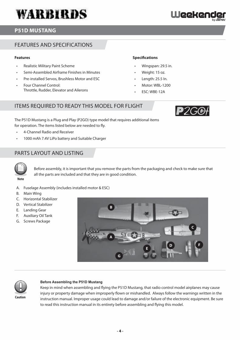
Before assembly, it is important that you remove the parts from the packaging and check to make sure that all the parts are included and that they are in good condition.
A. Fuselage Assembly (includes installed motor & ESC)B. Main Wing C. Horizontal Stabilizer D. Vertical StabilizerE. Landing GearF. Auxiliary Oil TankG. Screws Package
FEATURES AND SPECIFICATIONS
ITEMS REQUIRED TO READY THIS MODEL FOR FLIGHT
PARTS LAYOUT AND LISTING
Before Assembling the P51D MustangKeep in mind when assembling and � ying the P51D Mustang, that radio control model airplanes may cause injury or property damage when improperly � own or mishandled. Always follow the warnings written in the instruction manual. Improper usage could lead to damage and/or failure of the electronic equipment. Be sure to read this instruction manual in its entirety before assembling and � ying this model.
- 4 -
Tools Required for Assembly:
#0 and #1 Phillips Head Screwdrivers
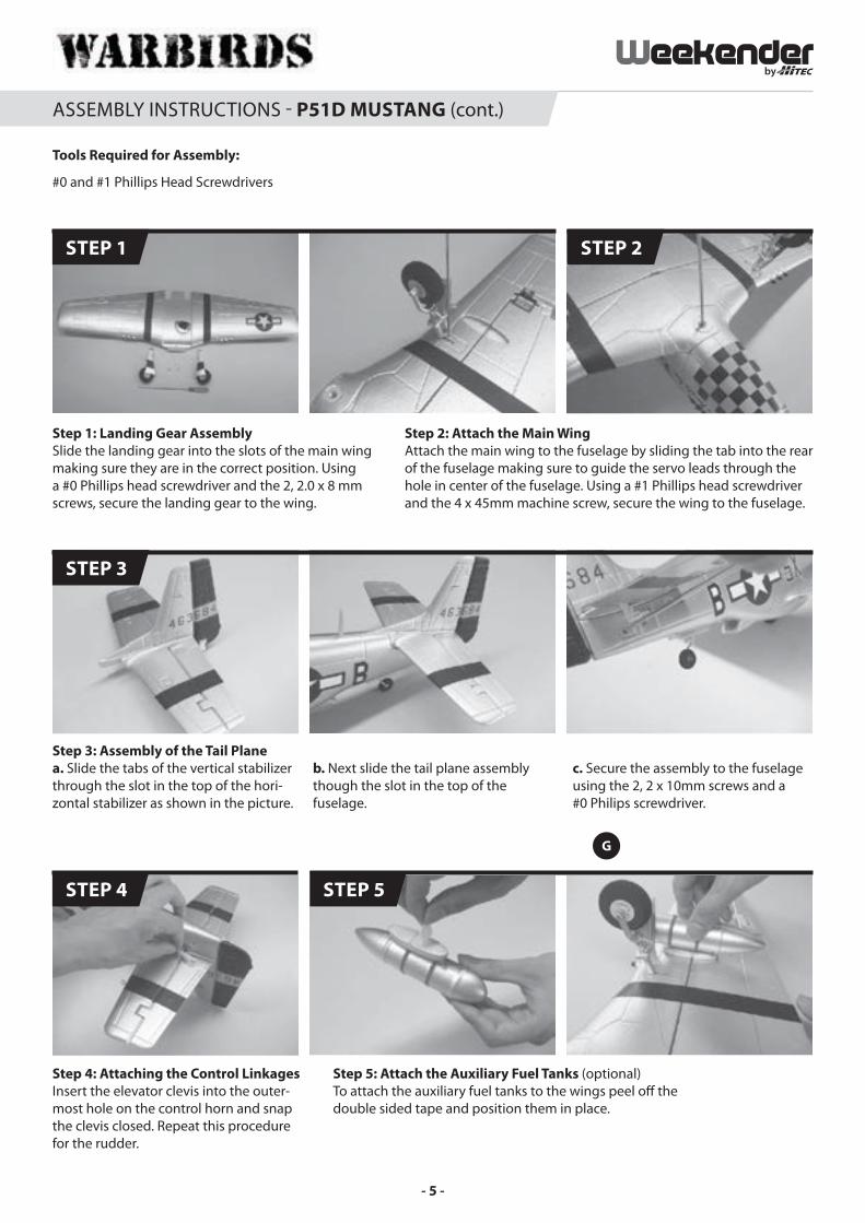
Step 1: Landing Gear AssemblySlide the landing gear into the slots of the main wing making sure they are in the correct position. Using a #0 Phillips head screwdriver and the 2, 2.0 x 8 mm screws, secure the landing gear to the wing.
Step 2: Attach the Main WingAttach the main wing to the fuselage by sliding the tab into the rear of the fuselage making sure to guide the servo leads through the hole in center of the fuselage. Using a #1 Phillips head screwdriver and the 4 x 45mm machine screw, secure the wing to the fuselage.
STEP 1
STEP 3
STEP 2
ASSEMBLY INSTRUCTIONS - P51D MUSTANG (cont.)
Step 4: Attaching the Control LinkagesInsert the elevator clevis into the outer-most hole on the control horn and snap the clevis closed. Repeat this procedure for the rudder.
Step 5: Attach the Auxiliary Fuel Tanks (optional) To attach the auxiliary fuel tanks to the wings peel o� the double sided tape and position them in place.
STEP 4 STEP 5
Step 3: Assembly of the Tail Planea. Slide the tabs of the vertical stabilizer through the slot in the top of the hori-zontal stabilizer as shown in the picture.
b. Next slide the tail plane assembly though the slot in the top of the fuselage.
c. Secure the assembly to the fuselage using the 2, 2 x 10mm screws and a #0 Philips screwdriver.
- 5 -
ASSEMBLY INSTRUCTIONS - P51D MUSTANG (cont.)
STEP 6 STEP 7
Fuselage
59011
Main Wing
59012
Horizontal Stabilizer
59013
Vertical Stabilizer
59014
Landing Gear
59015
Canopy
59016
Spinner
59017
Propeller
59018
Controlling Linkages
59036
WBL-1200 Brushless Motor
59040
*WS9 9g Servo - 150mm Lead (tail)**WS9 9g Servo - 300mm Lead (wing)
59037 * 59038 **
WBE-12A Brushless ESC
59039
SPARE PARTS - P51D MUSTANG
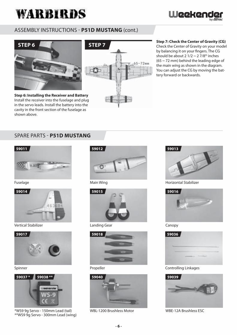
Step 6: Installing the Receiver and Battery Install the receiver into the fuselage and plug in the servo leads. Install the battery into the cavity in the front section of the fuselage as shown above.
Step 7: Check the Center of Gravity (CG) Check the Center of Gravity on your model by balancing it on your � ngers. The CG should be about 2 1/2 ~ 2 7/8th inches (65 ~ 72 mm) behind the leading edge of the main wing as shown in the diagram. You can adjust the CG by moving the bat-tery forward or backwards.
- 6 -

F4U CORSAIR
The F4U Corsair is a Plug and Play (P2GO) type model that requires additional items for operation. The items listed below are needed to � y.
• 4-Channel Radio and Receiver
• 1000 mAh 7.4V LiPo battery and Suitable Charger
Features
• Realistic Military Paint Scheme
• Semi-Assembled Airframe Finishes in Minutes
• Pre-installed Servos, Brushless Motor and ESC
• Four Channel Control:Throttle, Rudder, Elevator and Ailerons
Speci� cations
• Wingspan: 29.5 in.
• Weight: 14.8 oz.
• Length: 24 in.
• Motor: WBL-1300
• ESC: WBE-12A
Before assembly, it is important that you remove the parts from the packaging and check to make sure that all the parts are included and that they are in good condition.
A. Fuselage Assembly (includes installed motor & ESC)B. Main Wing C. Horizontal Stabilizer D. Vertical StabilizerE. Landing GearF. Guided MissilesG. Auxiliary Oil TankH. Screws PackageI. Glue
FEATURES AND SPECIFICATIONS
ITEMS REQUIRED TO READY THIS MODEL FOR FLIGHT
PARTS LAYOUT AND LISTING
Before Assembling the F4U CorsairKeep in mind when assembling and � ying the F4U Corsair, that radio control model airplanes may cause injury or property damage when improperly � own or mishandled. Always follow the warnings written in the instruc-tion manual. Improper usage could lead to damage and/or failure of the electronic equipment. Be sure to read this instruction manual in its entirety before assembling and � ying this model.
- 7 -
ASSEMBLY INSTRUCTIONS - F4U CORSAIR
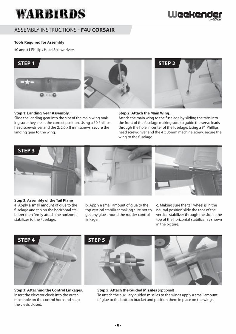
Step 1: Landing Gear Assembly. Slide the landing gear into the slot of the main wing mak-ing sure they are in the correct position. Using a #0 Phillips head screwdriver and the 2, 2.0 x 8 mm screws, secure the landing gear to the wing.
Step 2: Attach the Main Wing.Attach the main wing to the fuselage by sliding the tabs into the front of the fuselage making sure to guide the servo leads through the hole in center of the fuselage. Using a #1 Phillips head screwdriver and the 4 x 35mm machine screw, secure the wing to the fuselage.
STEP 1 STEP 2
Step 3: Attaching the Control Linkages. Insert the elevator clevis into the outer-most hole on the control horn and snap the clevis closed.
STEP 4
Step 5: Attach the Guided Missiles (optional) To attach the auxiliary guided missiles to the wings apply a small amount of glue to the bottom bracket and position them in place on the wings.
STEP 5
Tools Required for Assembly
#0 and #1 Phillips Head Screwdrivers
Step 3: Assembly of the Tail Planea. Apply a small amount of glue to the fuselage and tab on the horizontal sta-bilizer then � rmly attach the horizontal stabilizer to the Fuselage.
b. Apply a small amount of glue to the top vertical stabilizer making sure not to get any glue around the rudder control linkage.
c. Making sure the tail wheel is in the neutral position slide the tabs of the vertical stabilizer through the slot in the top of the horizontal stabilizer as shown in the picture.
STEP 3
- 8 -
ASSEMBLY INSTRUCTIONS - F4U CORSAIR (cont.)
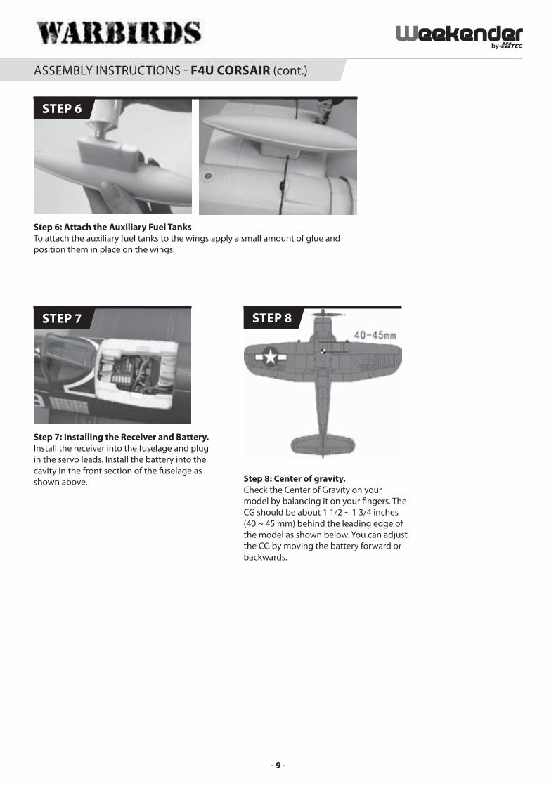
Step 7: Installing the Receiver and Battery. Install the receiver into the fuselage and plug in the servo leads. Install the battery into the cavity in the front section of the fuselage as shown above.
STEP 7
Step 6: Attach the Auxiliary Fuel Tanks To attach the auxiliary fuel tanks to the wings apply a small amount of glue and position them in place on the wings.
STEP 6
Step 10: Center of gravity.
STEP 8
Step 8: Center of gravity. Check the Center of Gravity on your model by balancing it on your � ngers. The CG should be about 1 1/2 ~ 1 3/4 inches (40 ~ 45 mm) behind the leading edge of the model as shown below. You can adjust the CG by moving the battery forward or backwards.
- 9 -

SPARE PARTS - F4U CORSAIR
Main Wing
59020
Fuselage
59019
Horizontal Stabilizer
59021
Vertical Stabilizer
59022
Spinner
59025
Landing Gear
59023
Propeller
59026
Controlling Linkages
59027
*WS9 9g Servo - 150mm Lead (tail)**WS9 9g Servo - 300mm Lead (wing)
59037 * 59038 **
WBL-1200 Brushless Motor
59040
WBE-12A Brushless ESC
59039
- 10 -
HAWKER HURRICANE MKIIB
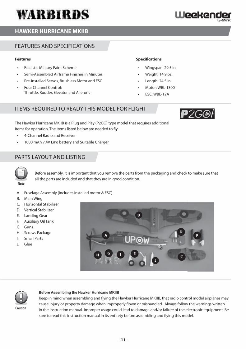
The Hawker Hurricane MKIIB is a Plug and Play (P2GO) type model that requires additional items for operation. The items listed below are needed to � y.
• 4-Channel Radio and Receiver
• 1000 mAh 7.4V LiPo battery and Suitable Charger
Features
• Realistic Military Paint Scheme
• Semi-Assembled Airframe Finishes in Minutes
• Pre-installed Servos, Brushless Motor and ESC
• Four Channel Control:Throttle, Rudder, Elevator and Ailerons
Speci� cations
• Wingspan: 29.5 in.
• Weight: 14.9 oz.
• Length: 24.5 in.
• Motor: WBL-1300
• ESC: WBE-12A
Before assembly, it is important that you remove the parts from the packaging and check to make sure that all the parts are included and that they are in good condition.
A. Fuselage Assembly (includes installed motor & ESC)B. Main Wing C. Horizontal Stabilizer D. Vertical StabilizerE. Landing GearF. Auxiliary Oil TankG. GunsH. Screws PackageI. Small PartsJ. Glue
FEATURES AND SPECIFICATIONS
ITEMS REQUIRED TO READY THIS MODEL FOR FLIGHT
PARTS LAYOUT AND LISTING
Before Assembling the Hawker Hurricane MKIIBKeep in mind when assembling and � ying the Hawker Hurricane MKIIB, that radio control model airplanes may cause injury or property damage when improperly � own or mishandled. Always follow the warnings written in the instruction manual. Improper usage could lead to damage and/or failure of the electronic equipment. Be sure to read this instruction manual in its entirety before assembling and � ying this model.
- 11 -
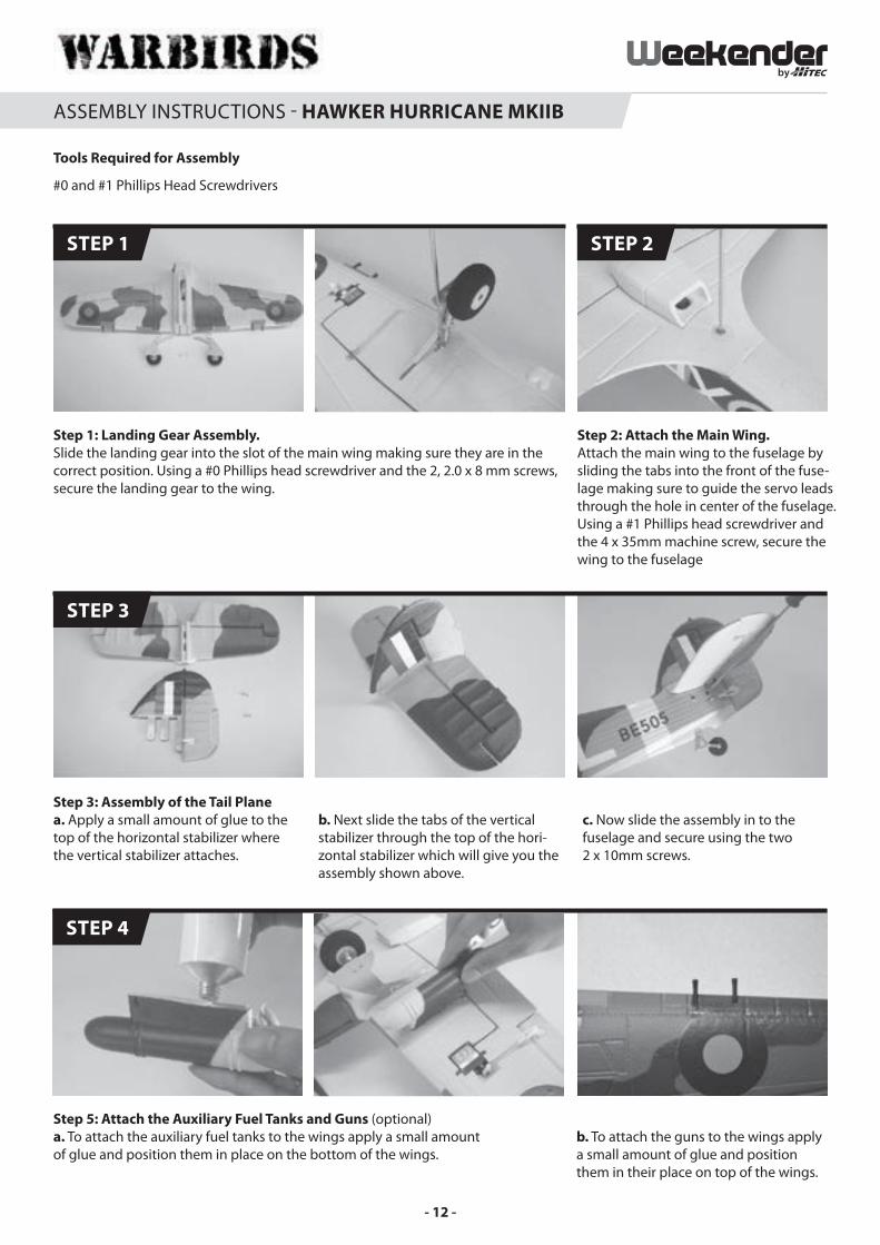
Step 1: Landing Gear Assembly.Slide the landing gear into the slot of the main wing making sure they are in the correct position. Using a #0 Phillips head screwdriver and the 2, 2.0 x 8 mm screws, secure the landing gear to the wing.
Step 2: Attach the Main Wing.Attach the main wing to the fuselage by sliding the tabs into the front of the fuse-lage making sure to guide the servo leads through the hole in center of the fuselage. Using a #1 Phillips head screwdriver and the 4 x 35mm machine screw, secure the wing to the fuselage
STEP 1 STEP 2
ASSEMBLY INSTRUCTIONS - HAWKER HURRICANE MKIIB
STEP 3
STEP 4
Step 3: Assembly of the Tail Planea. Apply a small amount of glue to the top of the horizontal stabilizer where the vertical stabilizer attaches.
b. Next slide the tabs of the vertical stabilizer through the top of the hori-zontal stabilizer which will give you the assembly shown above.
c. Now slide the assembly in to the fuselage and secure using the two 2 x 10mm screws.
Step 5: Attach the Auxiliary Fuel Tanks and Guns (optional) a. To attach the auxiliary fuel tanks to the wings apply a small amount of glue and position them in place on the bottom of the wings.
b. To attach the guns to the wings apply a small amount of glue and position them in their place on top of the wings.
Tools Required for Assembly
#0 and #1 Phillips Head Screwdrivers
- 12 -
ASSEMBLY INSTRUCTIONS - HAWKER HURRICANE MKIIB (cont.)
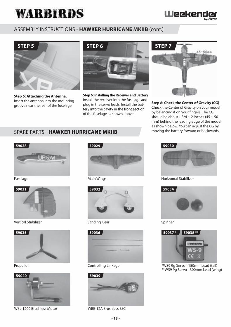
Step 6: Attaching the Antenna. Insert the antenna into the mounting groove near the rear of the fuselage.
STEP 5
Step 8: Check the Center of Gravity (CG) Check the Center of Gravity on your model by balancing it on your � ngers. The CG should be about 1 3/4 ~ 2 inches (45 ~ 50 mm) behind the leading edge of the model as shown below. You can adjust the CG by moving the battery forward or backwards.
STEP 7
Fuselage
59028
Main Wings
59029
Horizontal Stabilizer
59030
Vertical Stabilizer
59031
Landing Gear
59032
SPARE PARTS - HAWKER HURRICANE MKIIB
Spinner
59034
Propellor
59035
Controlling Linkage
59036
STEP 6
Step 6: Installing the Receiver and Battery Install the receiver into the fuselage and plug in the servo leads. Install the bat-tery into the cavity in the front section of the fuselage as shown above.
*WS9 9g Servo - 150mm Lead (tail)**WS9 9g Servo - 300mm Lead (wing)
59037 * 59038 **
WBL-1200 Brushless Motor
59040
WBE-12A Brushless ESC
59039
- 13 -
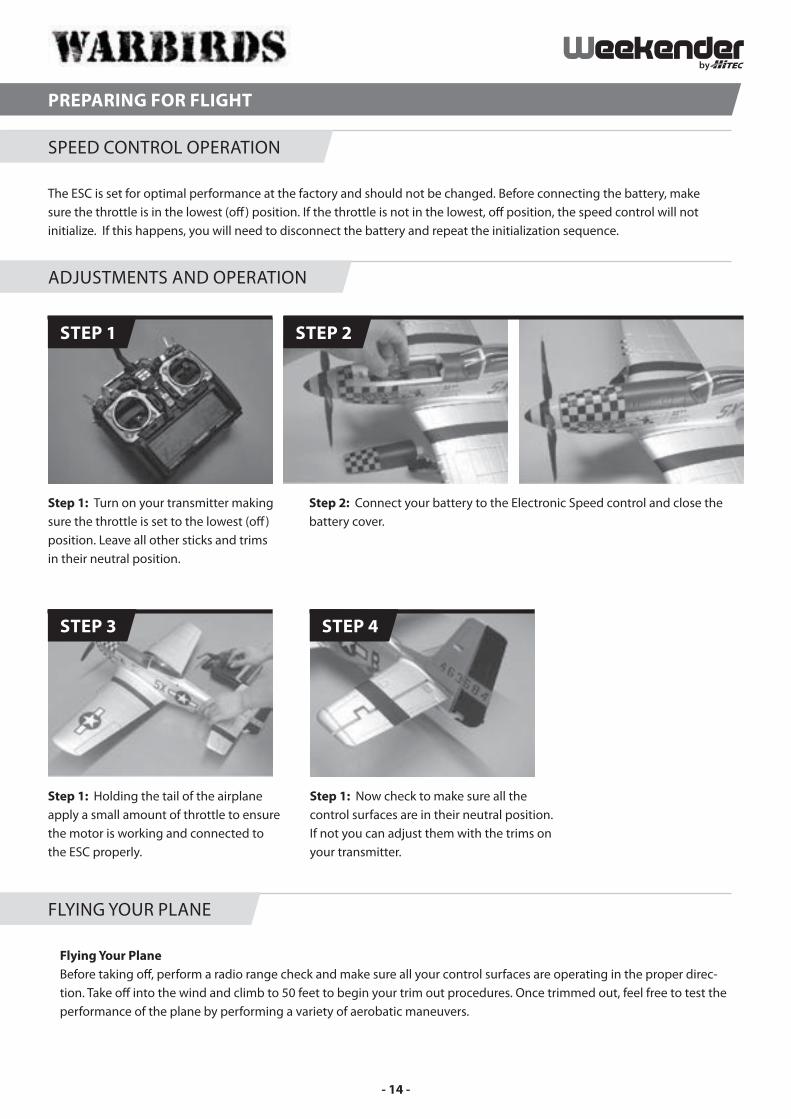
Flying Your Plane Before taking o� , perform a radio range check and make sure all your control surfaces are operating in the proper direc-tion. Take o� into the wind and climb to 50 feet to begin your trim out procedures. Once trimmed out, feel free to test the performance of the plane by performing a variety of aerobatic maneuvers.
PREPARING FOR FLIGHT
The ESC is set for optimal performance at the factory and should not be changed. Before connecting the battery, make sure the throttle is in the lowest (o� ) position. If the throttle is not in the lowest, o� position, the speed control will not initialize. If this happens, you will need to disconnect the battery and repeat the initialization sequence.
SPEED CONTROL OPERATION
ADJUSTMENTS AND OPERATION
FLYING YOUR PLANE
Step 1: Turn on your transmitter making sure the throttle is set to the lowest (o� ) position. Leave all other sticks and trims in their neutral position.
Step 1: Holding the tail of the airplane apply a small amount of throttle to ensure the motor is working and connected to the ESC properly.
Step 1: Now check to make sure all the control surfaces are in their neutral position. If not you can adjust them with the trims on your transmitter.
Step 2: Connect your battery to the Electronic Speed control and close the battery cover.
STEP 1
STEP 3 STEP 4
STEP 2
- 14 -

Weekender by Hitec Customer ServiceHelp is available from Hitec RCD USA, Inc. Customer Service through phone support: (858) 748-6948 and e-mail: [email protected]. Our o� ce is generally open Monday through Friday, 8:00 AM to 4:30 PM PST. These hours and days may vary by season. Every attempt is made to answer all incoming service calls. Should you get our voice mail, please leave your name and number and a sta� member will return your call.
LIMITED WARRANTYWeekender by Hitec guarantees the component parts in this kit to be free from defects in both materials and workmanship that exist at the time of purchase for a period of 90 days from the date of purchase. If any component part fails to function because of defects in materials or workmanship during this period, the manufacturer’s obligations are limited, at its discretion, to either, repair or replace the defective part.
This warranty does not cover any component part that has been damaged through use, modi� cation, misuse, abuse, accident or neglect; nor does it cover normal wear and tear. Additionally, this warranty is void if the component part has been altered or modi� ed or repaired by anyone other than Hitec RCD USA, Inc. or its authorized agents.
Hitec RCD USA, Inc. is not responsible for loss of use of the Weekender by Hitec model, or other incidental or consequential damages. Under no circumstances shall the Manufacturer or any of its representatives be held liable for injury to persons or property damage resulting from the assembly of the product or from the use of the � nal user assembled product. Further-more, no liability shall be attached to Weekender by Hitec or Hitec RCD USA, Inc. from the use of the � nal assembled product because: the product operates and is controlled by way of remote radio frequency; and outside radio frequencies may inter-fere with the product frequency, causing loss of control. Because an out-of-control model has the potential to cause personal injury and property damage, Weekender by Hitec or Hitec RCD USA, Inc. cannot be held liable for personal injury or property damage caused by the use or misuse of Weekender by Hitec model products. By the act of using the user-assembled prod-ucts, the user accepts all resulting liability. Some states do not allow exclusion of incidental or consequential damages, so the above limitations and exclusion may not apply to you.
Weekender by Hitec and Hitec RCD USA, Inc. hereby exclude any and all express warranties not speci� cally stated herein and all implied warranties of merchantability and � tness for a particular purpose. There are no warranties which extend beyond the description of the warranties contained within this document.
What to ReturnReturn only the component part that is defective in materials or workmanship. Please pack the unit carefully and insure it, as this warranty does not cover loss or damage in transit.
Hitec RCD USA, Inc.12115 Paine St.
Poway CA, 92064(858) 748-6948
SERVICE AND SUPPORT
WARRANTY
- 15 -

www.hitecrcd.com