Embed Size (px)
Citation preview
HC4300
Portable Flame/Plasma Cutting Machine Control
System User Manual
Operation Skills
Adtech (Shenzhen) CNC Technology Co., LTD
Address: F/5, 36th Building, MaJiaLong Industrial Park,
Nanshan District, Shenzhen City, China P.C: 518052
TEL:+86-755-2672 2719 (20 lines) FAX:+86-755-2672 2718
Website://www.adtechen.com

ADT-HC4300 Flame/Plasma Cutting Machine Control System
- 1 -
Copyright Warning
The property right in work regarding all the contents of this
manual is owned by Adtech (Shenzhen) CNC Technology Co.,
LTD (hereinafter referred to as Adtech), without the permission of
Adtech, any company or individual is not allowed to imitate, copy,
reproduce or translate this manual. Our company makes no
warranty, express representation or other imply regarding the
contents of this manual. Adtech and its employees assume no
responsibility for any direct or indirect information disclosure,
benefit loss or business termination due to this manual or the
products information described in it. In addition, the products and
their information described in this manual are only for the purpose
of reference, we reserve the right to amend the manual without
prior notice.
All Rights Reserved, Reprint Not Allowed .
Adtech (Shenzhen) CNC Technology Co., LTD
ADT-HC4300 Flame/Plasma Cutting Machine Control System
Version Upgrading Instruction
Program No. Version
Number
Modification
Date Instruction
XT20090101 2.0 2009/06/25 The Second Version
Remarks: the meanings of the four numbers in the version number are as follows:
Bank Main Version Number/ Bank Secondary Version Number/ Reservation
Notes:
1. This user manual is strictly emended and checked by ADTECH (SHENZHEN) CNC TECHNOLOGY CO., LTD, however, it is not guaranteed that the user manual has no any mistake or error.
2. ADTECH (SHENZHEN) CNC TECHNOLOGY CO., LTD commits itself to improve the product functions and the service quality consistently. Therefore, the company reserves the right of changing any products as described, any software program, and the content of the user manual, without prior notice.
- 2 -
ADT-HC4300 Flame/Plasma Cutting Machine Control System
- 3 -
Content
CHAPTER I. OPERATION SKILLS ......................................................... 5
HELP INFORMATION................................................................................. 5 RESTORE FACTORY DEFAULT ................................................................... 5 TWO KINDS OF OPERATING SPEED ........................................................... 5 ADJUSTMENT OF PROCESSING SPEED....................................................... 6 ADJUSTMENT OF MANUAL SPEED ........................................................... 7 CONTROL OF TURNING QUALITY ............................................................ 8 ADJUSTMENT OF LOW SPEED WHEN CUTTING THE THICK PLATE............ 12 PREHEATING TIME EXTEND OF FLAME CUTTING ................................... 13 POWER FAILURE TREATMENT................................................................ 14 BREAK POINT SETUP.............................................................................. 14 CHANGE OF CUTTING GUN NOZZLE ....................................................... 15 DISPLACEMENT PERFORATING............................................................... 15 MOVEMENT OF WORK PIECE.................................................................. 16 LINE AND POINT SELECTION .................................................................. 17 ARRAY................................................................................................... 18 MIRROR................................................................................................. 20 ROTATING.............................................................................................. 22 CALIBRATION ........................................................................................ 22 FIGURE LIBRARY ................................................................................... 26 COPY OF PROCESSING FILES .................................................................. 27 PARAMETER ADJUSTMENT OF FLAME/PLASMA CUTTING ....................... 27
CHAPTER II TROUBLESHOOTING..................................................... 30
WHY THE U-DISK CANNOT BE READ? .................................................... 30 WHY THERE IS AN ERROR IN THE CUTTING? .......................................... 30

ADT-HC4300 Flame/Plasma Cutting Machine Control System
- 4 -
WHY THE CUTTING QUALITY OF THE TURNING IS POOR? ....................... 30 WHY THE CUTTING SQUARE IS CHANGED TO RECTANGLE?.................... 31 WHY THE CUTTING CIRCLE IS CHANGED TO ELLIPSE? ........................... 31 WHY THERE IS WAVE SHAKE IN THE OPPOSITE ANGLES WHEN CUTTING
THE CIRCLE? .............................................................................................. 31 WHY THE MOTOR DOES NOT WORK OR IS SIMILAR TO DEATH WHEN IT IS
IN “AUTO” STATE? ..................................................................................... 31 WHY THE MOTOR DOES NOT WORK OR IS SIMILAR TO DEATH WHEN IT IS IN
“MANUAL” STATE? .................................................................................... 32 THE PROCESSING CODE HAS THE “RETURN” INSTRUCTIONS. HOWEVER,
WHY THE DEVICE DOES NOT RETURN TO THE HOME POSITION AFTER HAVING
FINISHED THE TRACK? ............................................................................... 32 WHY THE RIGHT ANGLE OF THE CUTTING SQUARE IS NOT VERTICAL? ... 32 WHY THE ANTI-INTERFERENCE PERFORMANCE OF PLASMA IS POOR? ... 32 WHY, ONE OF THE SOLENOID VALVES CANNOT WORK?.......................... 33
ADT-HC4300 Flame/Plasma Cutting Machine Control System
- 5 -
Chapter I. Operation skills
Help information
You can get the relevant help information by pressing [INS] in the first
level menu. For example, you can press [F1] (Auto) in start-up interface to
enter the Auto interface, then, press [INS] to get the help information. Press
[F6] (Help) in the upgrade interface to search the relevant help information.
Restore factory default
When the system parameter is adjusted by users to be abnormal,
which causes incorrect speed and precision, the users can press [F6]
(Upgrade) in the start-up interface → [F1] (Restore) → [F1] (Restore)
→ [OK] to restore the factory default. If the factory had not saved the
parameters, the system will not allow restoring, and relevant dialogue
boxes will be popped out.
Two kinds of operating speed
The system has two kinds of operating speed during the normal cutting
and processing:
1) Processing speed (Cutting speed): It is used in processing
instructions like G01 line, G02 clockwise circle, and G03
anti-clockwise.

ADT-HC4300 Flame/Plasma Cutting Machine Control System
2) Manual speed (operation speed when it is not cutting): It is used
in the instructions such as G00 idle move, manual return, G26
X return, G27 Y return, G28 X & Y return, pressing X+, X-, Y+,
Y- in auto/manual interface to move, and arcing in the manual
interface.
Therefore, the speed will be different in the normal processing based on
the different parameters. Usually, the cutting speed is slower than the idle
moving speed
Adjustment of processing speed
Processing speed is determined by the “Processing Limit Speed” in
“Control” interface and the “Speed” rate in “Auto Processing” interface.
- 6 -

ADT-HC4300 Flame/Plasma Cutting Machine Control System
Press [F4] (Parameter) in start-up interface → [F4] (Control)
Press [F1] (Auto) in start-up interface
Actual Processing Speed = Processing Limit Speed × Speed Rate
Note: Speed rate can be adjusted by pressing [F↑] and [F↓] on the
panel, or just the [F] key.
Adjustment of Manual Speed
Manual speed is determined by the “Manual Limit Speed” in “Control”
interface and the “Speed” rate in “Manual Processing” interface.
- 7 -
ADT-HC4300 Flame/Plasma Cutting Machine Control System
- 8 -
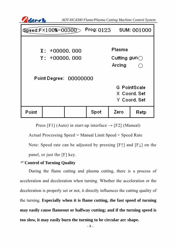
Press [F1] (Auto) in start-up interface → [F2] (Manual)
Actual Processing Speed = Manual Limit Speed × Speed Rate
Note: Speed rate can be adjusted by pressing [F↑] and [F↓] on the
panel, or just the [F] key.
Control of Turning Quality
During the flame cutting and plasma cutting, there is a process of
acceleration and deceleration when turning. Whether the acceleration or the
deceleration is properly set or not, it directly influences the cutting quality of
the turning. Especially when it is flame cutting, the fast speed of turning
may easily cause flameout or halfway cutting; and if the turning speed is
too slow, it may easily burn the turning to be circular arc shape.
ADT-HC4300 Flame/Plasma Cutting Machine Control System
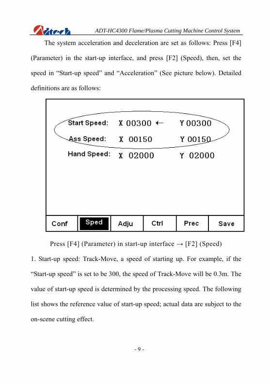
The system acceleration and deceleration are set as follows: Press [F4]
(Parameter) in the start-up interface, and press [F2] (Speed), then, set the
speed in “Start-up speed” and “Acceleration” (See picture below). Detailed
definitions are as follows:
Press [F4] (Parameter) in start-up interface → [F2] (Speed)
1. Start-up speed: Track-Move, a speed of starting up. For example, if the
“Start-up speed” is set to be 300, the speed of Track-Move will be 0.3m. The
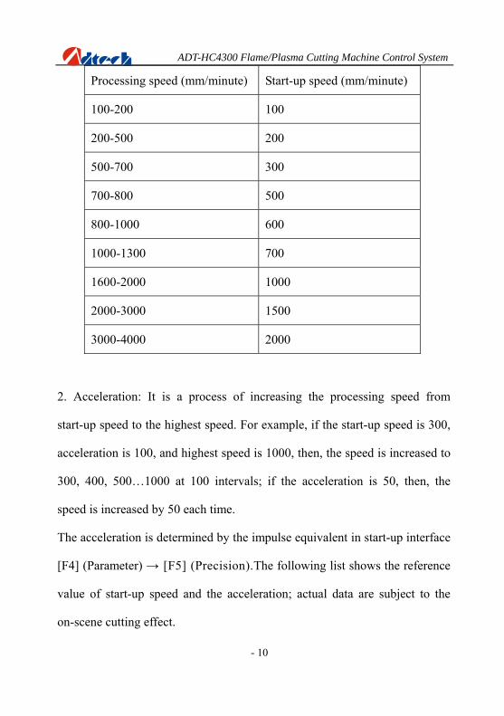
value of start-up speed is determined by the processing speed. The following
list shows the reference value of start-up speed; actual data are subject to the
on-scene cutting effect.
- 9 -
ADT-HC4300 Flame/Plasma Cutting Machine Control System
- 10
Processing speed (mm/minute) Start-up speed (mm/minute)
100-200 100
200-500 200
500-700 300
700-800 500
800-1000 600
1000-1300 700
1600-2000 1000
2000-3000 1500
3000-4000 2000
2. Acceleration: It is a process of increasing the processing speed from
start-up speed to the highest speed. For example, if the start-up speed is 300,
acceleration is 100, and highest speed is 1000, then, the speed is increased to
300, 400, 500…1000 at 100 intervals; if the acceleration is 50, then, the
speed is increased by 50 each time.
The acceleration is determined by the impulse equivalent in start-up interface
[F4] (Parameter) → [F5] (Precision).The following list shows the reference
value of start-up speed and the acceleration; actual data are subject to the
on-scene cutting effect.

ADT-HC4300 Flame/Plasma Cutting Machine Control System
- 11
Impulse Equivalent Acceleration (mm/minute)
0.001000-0.002000 10
0.002000-0.003000 20
0.003000-0.004000 30
0.004000-0.005000 40
0.005000-0.006000 50
0.006000-0.007000 60
0.007000-0.008000 70
0.008000-0.009000 80
0.009000-0.010000 90
0.010000-0.011000 100
0.011000-0.012000 110
0.012000-0.013000 120

ADT-HC4300 Flame/Plasma Cutting Machine Control System Adjustment of low speed when cutting the thick plate
Press [F4] (Parameter) in start-up interface → [F2] (Speed)
During the flame cutting when there needs to cut the thick steel
plate, and the cutting speed cannot achieve the required slow speed even
the speed rate has been adjusted to limit low percent, then, you just have
to set a corresponding number in the “Start-up speed” option as above
picture. For example, if the “Start-up speed” is set to be 100, then, the
lowest speed during the processing can be as low as 0.1m.
- 12
(Principle: If the processing speed is lower than start-up speed, the
system is run at start-up speed.)

ADT-HC4300 Flame/Plasma Cutting Machine Control System Preheating time extend of flame cutting
Total preheating time and the current preheating time will be shown on the
right bottom of the interface when preheating is carried out; on the left
bottom there will show “Stop preheating, press [START]; Extend preheating,
press [STOP].” As prompted, if you press [START], the system will stop
preheating immediately and go to the next action; if you press [STOP], the
preheating time will be extended without limit. Press [START] to stop if the
preheating is enough, and the system will save the “Current preheating time”
automatically as the “Total preheating time” in the future.
- 13
ADT-HC4300 Flame/Plasma Cutting Machine Control System
- 14
Power Failure Treatment
In order to avoid the waste of raw materials caused by the sudden power
failure, the system equips with a power-off protection function. If the device
is powered off during the processing, the system will automatically save the
last processing track as a break point. When the power supply is resumed and
you want to resume the coordinate before power-off, you just have to press
[F6] (Break point) in the Auto interface or [F4] (Break point) in the Manual
interface.
Note: Do not move the cutting nozzle when the power is off, and
make sure to set the current coordinate when the power is resumed;
otherwise, all the memory coordinate will be wrong.
Break point setup
If you exit the automatic processing interface and want to return next
time, you need to resume to the current stop coordinate. This can be made by
pressing “Pause” during the automatic processing and pressing [F6] (Break
point), then, the system will automatically save the current processing point
(where the cutting nozzle is located) as a break point. This point is saved
forever; no matter it is power off or on. The coordinate will be the saved
break point coordinate when you enter the “Auto” interface next time, as
long as the current program has not changed.

ADT-HC4300 Flame/Plasma Cutting Machine Control System
If you restart the device after the power-off, you just have to press [F6]
(Break point) in the “Auto” interface to restore the break point, and press the
corresponding function keys (Preheating & Perforating, open the cutting
Oxygen, etc.) to resume processing.
Change of cutting gun nozzle
If cutting gun nozzle is damaged during the processing, please follow
the following steps to change it:
In automatic processing → Press [STOP] → Press [F6] (Break
point) → Press the corresponding [X+], [X-], [Y+], and [Y-] keys to move
the cutting gun to a proper place for changing the nozzle → Press
[START], and the coordinate will be moved to the current break point
automatically → Press [Cutting Oxygen], and [START] key to go on the
follow-up processing.
Displacement perforating
B
B
A
Picture 1 Picture 2
- 15
ADT-HC4300 Flame/Plasma Cutting Machine Control System
As Picture 1, the out square is the steel plate and the inside square is the
work piece to be cut. Assuming that it is to cut the work piece from point A
and the steel plate is of thick materials; then, it will cost a lot of time to
perforate. However, if it is to cut from the edge of steel plate (point B), the
time of preheating perforating may be saved. Detailed operations are as
follows:
In automatic processing → Press [STOP] → Press [F6] (Break
point) → Press the corresponding X, and Y keys to move the cutting gun
to the edge of the steel plate → Preheating → Press [Cutting Oxygen],
and [START], and it will automatically cut the work piece to the break point
before, then, go on cutting the follow-up tracks.
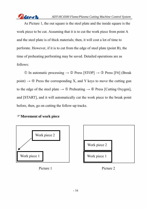
Movement of work piece
- 16
Picture 1 Picture 2
Work piece 1
Work piece 2
Work piece 2
Work piece 1

ADT-HC4300 Flame/Plasma Cutting Machine Control System
- 17
To save the steels during the processing, you can move the tracks of
work piece to a certain place for processing when cutting some kinds of
figures. As shown in above pictures, the out frame is the steel plate, and the
inside frame is the figure to be cut. For example, it may waste many
materials if you cut the “work piece 2” directly after having cut the “work
piece 1”, because they are a certain distance away. Therefore, you can move
the track of work piece to a proper place as Picture 2 before cutting, which
can save many materials. Detailed operations are as follows:
Press [STOP] key after you have cut the “work piece 1” → Press
[X+], [X-], [Y+], and [Y-] to move the cutting gun to the proper position.
Line and point selection
When a processing piece consists of many lines or perforating points
and it is required to start cutting from one of the lines or perforating points in
the actual cutting, you can press [F1] (Auto) → [F4] (Figure) → [F4]
(Process) and [F2] (Select the line) or [F3] (Select the point) to select the line
and point.

ADT-HC4300 Flame/Plasma Cutting Machine Control System
- 18
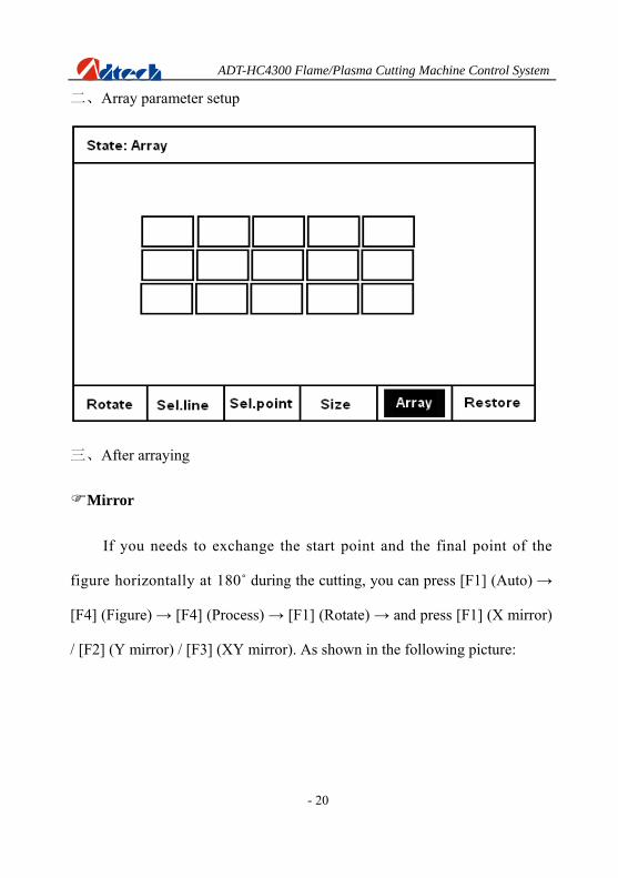
Array
When you need to cut a single figure for several times, you can use the
array function to copy the figure first as the following picture. G code has the
following requirements when arraying:
1) The processing code is required to return to the original point after
the processing. If it has not returned, you can add a line of G28
under the last M08 instruction of the processing file, which means
X and Y-axis return to the reference point at the same time.
2) The end of processing file should be ended with M02.
1) You can rotate the figure after the arraying, but you cannot
array after the figure rotating.
2) You cannot rotate the figure when it is processed halfway, or
after the point and line are selected.
3) Press [F4] (Size) after the arraying to see whether the size fit the
steel plate. Press [F6] (Restore) if you want to array again.

ADT-HC4300 Flame/Plasma Cutting Machine Control System
- 19
一 、Before arraying
ADT-HC4300 Flame/Plasma Cutting Machine Control System
二、Array parameter setup
三、After arraying
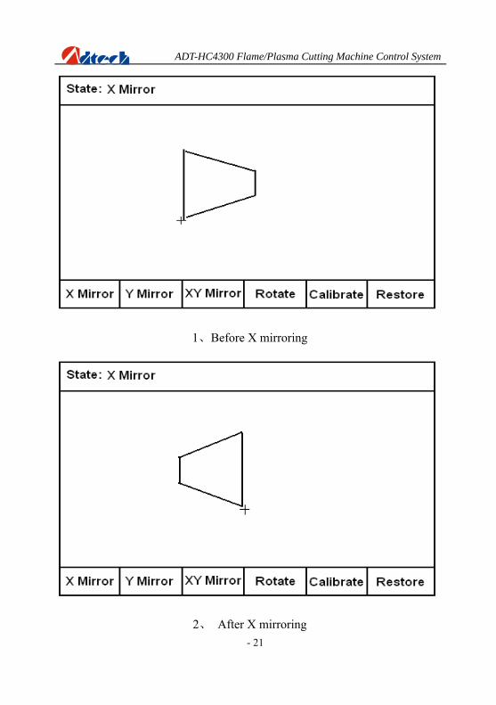
Mirror
If you needs to exchange the start point and the final point of the
figure horizontally at 180˚ during the cutting, you can press [F1] (Auto) →
[F4] (Figure) → [F4] (Process) → [F1] (Rotate) → and press [F1] (X mirror)
/ [F2] (Y mirror) / [F3] (XY mirror). As shown in the following picture:
- 20
ADT-HC4300 Flame/Plasma Cutting Machine Control System
- 21
1、Before X mirroring
2、 After X mirroring
ADT-HC4300 Flame/Plasma Cutting Machine Control System Rotating
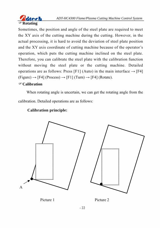
Sometimes, the position and angle of the steel plate are required to meet the XY axis of the cutting machine during the cutting. However, in the actual processing, it is hard to avoid the deviation of steel plate position and the XY axis coordinate of cutting machine because of the operator’s operation, which puts the cutting machine inclined on the steel plate. Therefore, you can calibrate the steel plate with the calibration function without moving the steel plate or the cutting machine. Detailed operations are as follows: Press [F1] (Auto) in the main interface → [F4] (Figure) → [F4] (Process) → [F1] (Turn) → [F4] (Rotate).
Calibration
When rotating angle is uncertain, we can get the rotating angle from the
calibration. Detailed operations are as follows:
Calibration principle:
- 22
A
Picture 1 Picture 2

ADT-HC4300 Flame/Plasma Cutting Machine Control System
1). In Picture 1, the large frame (Real line) is the steel plate, the small
frame (Dashed line) is the figure to be cut, and point A is the start point
of the cutting gun. If it is cut according to Picture 1, the figure outside
may not be cut; and if it is cut when the start point is moved to the
middle of the steel plate as Picture 2, obviously it will waste the steel
plate.
2). At this point, without moving the steel plate, you just have to figure
out the slope angle of the plate, and incline the figure to be processed
at the corresponding angle before cutting effectively.
Way of calibrating the steel plate:
B
A
1) As above picture, point A is the start point of cutting gun.
You can figure out the slope angle of the steel plate by
- 23

ADT-HC4300 Flame/Plasma Cutting Machine Control System
moving the cutting gun to any point of its base line. Press
[X+] → [Y-], or [Y-] → [X+]; then, press [OK] to confirm.
2) Then, the figure displayed on the controller will be rotated
at a certain degree. The position of figure to be processed
and the steel plate is shown as follows:
3). If the steel plate is inclined as follows, then, the calibration
method is as below:
- 24

ADT-HC4300 Flame/Plasma Cutting Machine Control System
B
A
Press [X+] → [Y+], or [Y+] → [X+], then, press [OK] to confirm. The
position of figure to be processed and the steel plate is shown as
follows:
- 25

ADT-HC4300 Flame/Plasma Cutting Machine Control System Figure library
For the convenience of the processing, and for decreasing the
workload and increasing the usability of the system, the system
especially includes 33 figures of normal machining parts. Users can
press [F2] (Figure library) in the start-up interface to enter the figure
library, and choose the corresponding figure to process. The figures are
as follows:
- 26

ADT-HC4300 Flame/Plasma Cutting Machine Control System
- 27
Copy of processing files
You can either copy the processing file of U-disk to the controller, or
copy the processing file of controller to the U-disk. When copying files from
controller to U-disk, the copy is saved in the “PRG” folder created by the
system automatically.
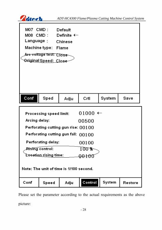
Parameter adjustment of flame/plasma cutting
The system has two kinds of cutting techniques, flame cutting, and
plasma cutting. If the device supports flame/plasma cutting, and the user
wants to switch between these two techniques, make sure to press [F4]
(Parameter) in the start-up interface → [F1] (Configuration) and [F4]
(Control) to change the corresponding parameter. Here is the
introduction of plasma cutting setup. See the following picture:
ADT-HC4300 Flame/Plasma Cutting Machine Control System
- 28
Please set the parameter according to the actual requirements as the above
picture:
ADT-HC4300 Flame/Plasma Cutting Machine Control System
- 29
1). Arc voltage detection:
If the device is equipped with auto-adjusting device, which usually
has the arc voltage detecting-instrument, you need to set the arc
voltage detection “On”. If there is no this function, you can set it to be
“Off”.
2). Initial location:
It is an action of auto-adjusting location of cutting gun before plasma
arcing. If the device owns this function, it is necessary to set it to be
“On”, and set the “Location rising time” according to the actual
requirements.
3). Height-adjusting control:
The system will have a process of acceleration and deceleration when
cutting the turning of the steel plate. If the device is equipped with
auto-adjusting instrument, it is necessary to turn it off when the system
speed is decreased to a certain degree; otherwise, the feedback change
of arc caused by the decrease of the speed will lower the cutting gun,
touching the steel plate. It is usually to set the “Height-adjusting
control” to be 80%, which means that the system will cancel/enable the
auto-adjusting function automatically when the turning speed is lower to
/over the 80% of the processing speed.

ADT-HC4300 Flame/Plasma Cutti chine Control System ng Ma
- 30
Chapter II Troubleshooting
Why the U-disk cannot be read?
Answer: If the controller cannot read the U-disk, you can change the
“File system” of U-disk on the computer, and then format it. Detailed
operations are as follows: Insert the U-disk to the computer → Open “My
Computer” → Find the removable U-disk → Right click the mouse → Click
“Format (A)” → change the format of “File system” from “FAT32” to “FAT”
→ Click “Start” to start formatting. Copy the processed files to the U-disk to
test again. Change for a new U-disk if it still cannot be read.
Why there is an error in the cutting?
Answer: Check whether the impulse equivalent in the precision setup
has been changed; or calibrate the impulse equivalent again.
Why the cutting quality of the turning is poor?
Answer: Please check whether the start-up speed and the acceleration
are set to be the reasonable values.
ADT-HC4300 Flame/Plasma Cutting Machine Control System
- 31
Why the cutting square is changed to rectangle?
Answer: please check whether the impulse equivalent is correct, and
whether the actual precision of X or Y movement is correct. If these two
values are correct, check whether the roller and the slide rail of the machine
are of no failures.
Why the cutting circle is changed to ellipse?
Answer: please check whether the impulse equivalent is correct, and
whether the actual precision of X or Y movement is correct. If these two
values are correct, check whether the roller and the slide rail of the machine
are of no failures.
Why there is wave shake in the opposite angles when cutting the circle?
Answer: Please adjust the backlash of the “Adjustment” in “Parameter”.
Why the motor does not work or is similar to death when it is in “Auto” state?
Answer: Please check the “Auto speed limit” to see whether it is a
proper speed, and check whether percentage of manual processing is too low.
ADT-HC4300 Flame/Plasma Cutting Machine Control System
- 32
Why the motor does not work or is similar to death when it is in “Manual” state?
Answer: Please check the “Manual speed limit” to see whether it is a
proper speed, and check whether percentage of manual processing is too low.
The processing code has the “Return” instructions. However, why the device does not return to the home position after having finished the track?
Answer: Please check the “Manual speed limit” to see whether it is a
proper speed, and check whether percentage of manual processing is too low.
Why the right angle of the cutting square is not vertical?
Answer: Debug the start-up speed and the acceleration of “Speed” in
“Parameter” again.
Why the anti-interference performance of plasma is poor?
Answer: Check whether all ground wires are connected well, or whether
the external power filter is isolating the high frequency.

ADT-HC4300 Flame/Plasma Cutting Machine Control System
- 33
Why, one of the solenoid valves cannot work?
Answer: You can judge whether it is caused by the system damage or
relay/solenoid valves damage in the following ways.
1). Change for a new solenoid valve of the same type to judge whether
it is broken, or press [Ignition] in the “Auto” interface, and press
[Preheat Oxygen], [Acetylene] and [Cutting Oxygen] to output a signal
manually, then, use a multimeter to test the input end of the solenoid
valve to see whether there is voltage signal.
2). If there is no voltage signal in the input end of the solenoid valve,
then, open the case and use the same method as above to test the input
end of the relay to see whether there is voltage signal, and to judge
whether it is damaged or not.
3). If the relay has no voltage signal, that may be the damage of output
end of NCS. Change for the backup output according to the following
steps.
4). Open the case and the output port as the following picture:
ADT-HC4300 Flame/Plasma Cutting Machine Control System
- 34
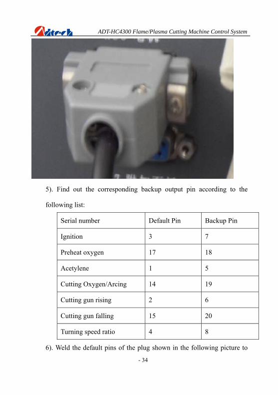
5). Find out the corresponding backup output pin according to the
following list:
Serial number Default Pin Backup Pin
Ignition 3 7
Preheat oxygen 17 18
Acetylene 1 5
Cutting Oxygen/Arcing 14 19
Cutting gun rising 2 6
Cutting gun falling 15 20
Turning speed ratio 4 8
6). Weld the default pins of the plug shown in the following picture to

ADT-HC4300 Flame/Plasma Cutting Machine Control System
the backup pins according to the above corresponding connection.
7). Connect to the power supply after the installation; in the start-up
interface, press [F5] (Diagnose) → [F2] (Define), use [Y↑] and [Y↓]
to select upwards and downwards, and use [X→], [X←] to select
the state, then, press “Save” to change the corresponding port to the
backup state.
- 35


![Plasma Cutting[1]](https://img.pdfslide.net/doc/110x75/55cf99f7550346d0339fedea/plasma-cutting1.jpg)