Embed Size (px)
Citation preview
Operational continuityABB H+Line safety and reliability, switchboards and devices for medical locations
2 | H+Line - Operational continuity in hospital segment
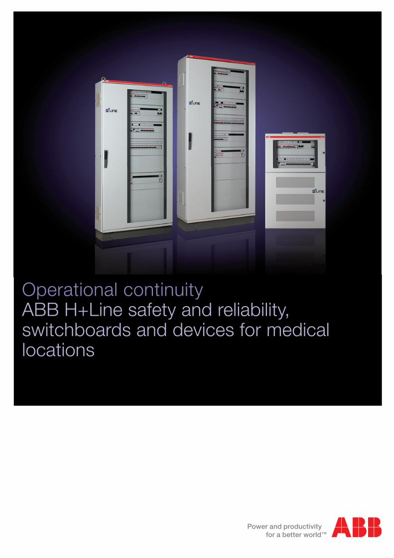
ABB technology and safety in hospital segment
Over ten years’ experience, state-of-the-art solutions offered to the most important Italian hospitals, a complete and performing range of products: this is H+Line, an ABB products range specific for group 2 medical locations, where operational continuity and reliability are key requirements for patients’ and medical staff’s safety and protection
Helpful for designers
What Standards say is explained by everybody. ABB tells
what Standards don’t say. The “Practical guide for group 2
medical locations” can be a useful daily tool to be consulted
for supporting designers and installers in each step of the
design and installation process of group 2 medical locations
electrical plants.
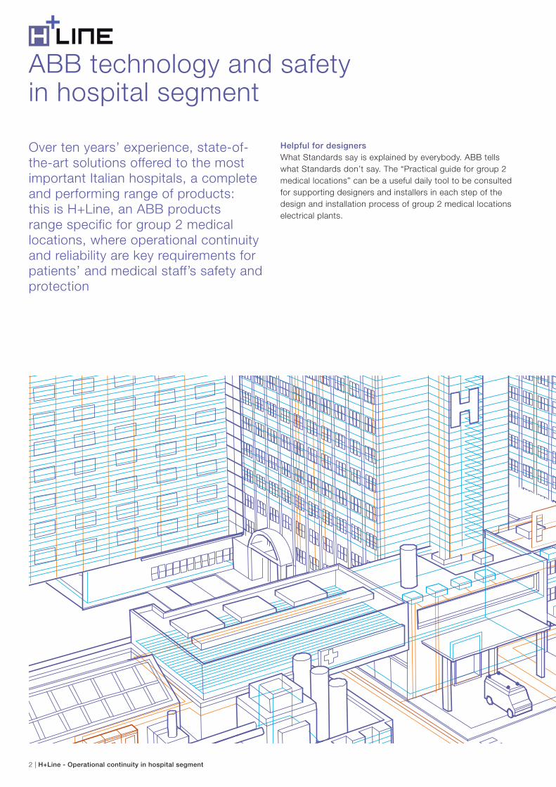
H+LineGuida pratica per ambienti ospedalieri di gruppo 2
H+Line - Operational continuity in hospital segment | 3
The document has been developed in a tight collaboration
with ABB customers. The aim is to add practical solutions,
ideas and plant design suggestions coming from the field to
fundamental standards.
Thus the “Practical guide to group 2 medical locations” turns
into a real help, full of examples, and a useful tool even for the
ones designing hospital plants for the first time ever. In the
practical guide, ABB customers will find at their complete
disposal all the expertise of a leading company which has
always been promoting and sustaining safety.
4 | H+Line - Operational continuity in hospital segment
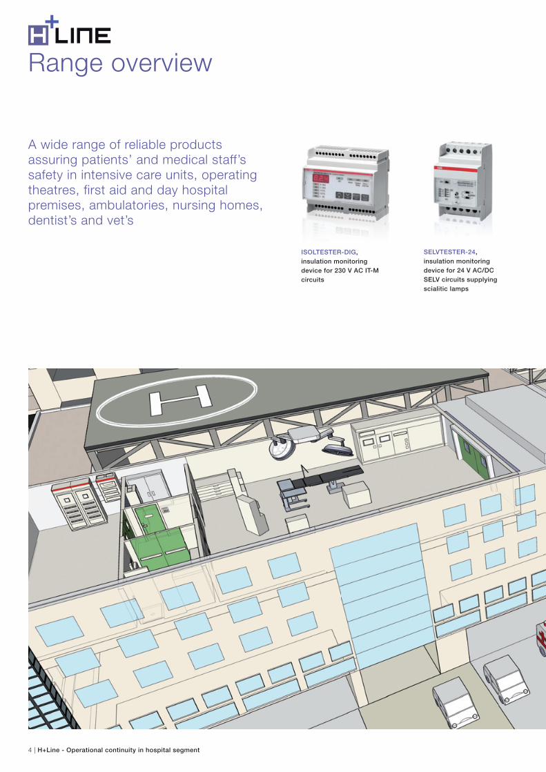
ISOLTESTER-DIG,
insulation monitoring
device for 230 V AC IT-M
circuits
SELVTESTER-24,
insulation monitoring
device for 24 V AC/DC
SELV circuits supplying
scialitic lamps
A wide range of reliable products assuring patients’ and medical staff’s safety in intensive care units, operating theatres, first aid and day hospital premises, ambulatories, nursing homes, dentist’s and vet’s
Range overview
H+Line - Operational continuity in hospital segment | 5
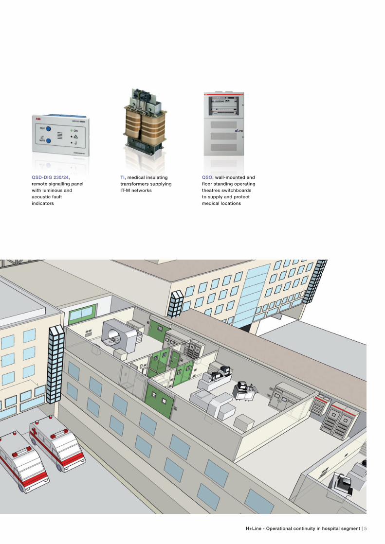
QSD-DIG 230/24,
remote signalling panel
with luminous and
acoustic fault
indicators
QSO, wall-mounted and
floor standing operating
theatres switchboards
to supply and protect
medical locations
TI, medical insulating
transformers supplying
IT-M networks
6 | H+Line - Operational continuity in hospital segment
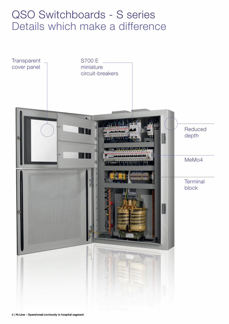
Transparent cover panel
S700 E miniature circuit-breakers
Terminal block
MeMo4
Reduced depth
QSO Switchboards - S seriesDetails which make a difference
H+Line - Operational continuity in hospital segment | 7
Transparent cover panel
A split opening in the cover panel enables to operate on the
modular devices without opening the compartment beneath
where the transformer and the terminal block are placed.
S700 E miniature circuit-breakers
The S700 main circuit-breaker placed in the upstream IT
section of the insulation transformer ensures total selectivity
up to 10 kA with all downstream circuit-breakers.
They can be equipped with a signalling contact in order to
remotely control the status of the lever.
Reduced depth
The narrow depth of the enclosure makes the installation
easier even inside cupboards, compartments or recesses,
thanks to the ArTu M series single-piece structure.
MeMo4
Installation and assembly instructions, electrical layouts and all
the business documentation related with the H+Line offer are
supplied together with the switchboard. Thanks to its USB
MeMo4 modular memory, it is possible to file further
documents such as testing certificates, declarations of
conformity and results of the periodic tests, thus preventing
them from being damaged or lost in time.
Terminal block
All terminal blocks have been studied in such a way as to
guarantee correct connections between all switchboard
equipment, ensuring mechanical separation between
the circuits.
In order to satisfy the needs of group 2 medical locations, ABB supplies preassembled wall-mounted and floor standing QSO electrical switchboards, complete with TI-S insulating transformer and ISOLTESTER-DIG-RZ insulation monitoring device to detect and signal promptly the first fault to earth.
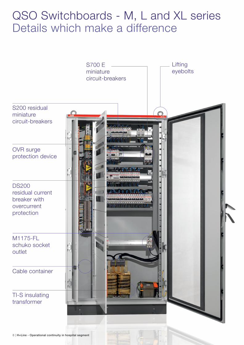
QSO Switchboards - M, L and XL seriesDetails which make a difference
Liftingeyebolts
S200 residualminiature circuit-breakers
DS200 residual current breaker with overcurrent protection
S700 E miniature circuit-breakers
M1175-FL schuko socket outlet
Cable container
TI-S insulating transformer
OVR surge protection device
8 | H+Line - Operational continuity in hospital segment
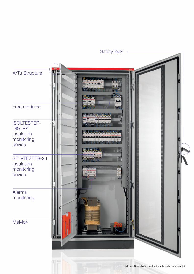
MeMo4
ISOLTESTER-DIG-RZ insulation monitoring device
Free modules
SELVTESTER-24 insulation monitoring device
Alarms monitoring
Safety lock
ArTu Structure
H+Line - Operational continuity in hospital segment | 9
10 | H+Line - Operational continuity in hospital segment
QSO Switchboards - M, L and XL seriesDetails which make a difference
S200 miniature circuit-breakers
These protect the downstream circuits of the IT-M section
against overloads and short-circuits, assuring reliability and
safety during the operations.
OVR surge protection device
It has been designed in order to safeguard the electrical
systems and equipment from any transient and impulsive
over-voltages.
OVR surge protective devices, installed in both the emergency
and safety sections, are coordinated with suitable back up
protection in order to avoid circuit overloads during the
devices useful life. All surge protective devices are equipped
with removable cartridges and signalling contacts in order to
optimize maintenance operations, and operational continuity.
S700 E miniature circuit-breakers
The S700 main circuit-breaker placed in the upstream IT section
of the insulation transformer ensures total selectivity up to
10 kA with all downstream circuit-breakers. Furthermore it
protects the insulating transformers from overloads.
They can be equipped with a signalling contact in order to
remotely control the status of the lever (see page 51 for the
S700 selectivity table).
M1175-FL schuko socket outlet
QSO switchboards are equipped with a socket outlet which is
useful to supply measurement devices and tools used during
maintenance. This socket is protected by an integrated fuse
and is equipped with an indicator lamp that allows detecting
whenever the auxiliary circuit has been supplied, even in the
darkness.
Cable container
Artu K series floor standing switchboards are equipped with a
cable container that makes installation and wiring easier, both
for the electrical systems distributed along the false
cieling, as under the floor.
It is possible to reach any terminal block in a comfortable way.
Finally, there is a copper equipotential bonding busbar which
may lodge up to 20 additional connections, providing
grounding connections to all the external masses which are
present in the medical premises, and avoiding the creation of
further cascade sub-nodes that are not allowed.
TI-S insulating transformer
Specifically designed and assembled for medical use
according to the IEC EN 61558-2-15, it ensures protection
against indirect contacts without the need to interrupt the
circuit automatically upon the first grounding fault.
Thanks to its two PT100 temperature probes, on primary and
secondary winding, it is possible to monitor the transformer
over temperature produced by any eventual overload, and
therefore anticipating any breakdown.
The transformer is mounted on the base of the switchboard in
order to ease handling and installation operations.
DS200 residual current breaker with overcurrent protection
They protect emergency section TN-S terminal circuits from
any direct and indirect contacts. These lines feed the lighting
system, the radiological and the general purpose socket
outlets, mounted outside the patients’ environment.
Lifting eyebolts
They allow immediate and safe wall fastening.
H+Line - Operational continuity in hospital segment | 11
MeMo4
Installation and assembly instructions, electrical layouts and all
the business documentation related with the H+Line offer are
supplied together with the switchboard. Thanks to its USB
MeMo4 modular memory, it is possible to file further
documents such as testing certificates, declarations of
conformity and results of the periodic tests, thus preventing
them from being damaged or lost in time.
ISOLTESTER-DIG-RZ insulation monitoring device
This is an insulation monitoring device for group 2 medical
locations fully compliant with the IEC 60364-7-710 reference
standard. It integrates all the performances established by the
reference standard, such as overload and overcurrent
monitoring, together with traditional IT system earthing
insulation measurement.
Safety lock
This is a door with a key lock system in order to avoid
undesired interventions by non authorized personnel.
SELVTESTER-24 insulation monitoring device
QSO “Premium” are equipped with 24 V SELV line supplying
the scialitic lamp.
SELVTESTER-24 monitors extremely low voltage circuits.
IEC 60364-7-710 reference standard does not impose
monitoring of such circuits, but, it is possible that during regular
handling of the lamp some conductors, detaching themselves
from the terminals, may enter into contact with the metal
housing. Therefore SELVTESTER-24 detects the damage as
soon as it happens, and consequently improve operational
continuity.
Alarms monitoring
High end configurations are equipped with I/O modules for
alarms management. In particular it is possible to control the
status of the main circuit-breaker and signalling contacts of the
OVR and ISOLTESTER, by means of the KNX bus.
ArTu Structure
Floor standing QSO switchboards are composed of modular
ArTu K series enclosures. The switchboards are equipped with
venting grooves that guarantee proper natural convection,
useful to dissipate the heat produced by the transformer during
its normal functioning.
Free modules
Switchboard flexibility is ensured by the possibility of inserting
further equipment that may be necessary to complete the
system or for possible future expansions.
E210 indicator lamp
Thanks to the green LED indicator lamp it is possible to see in
a blink whether the switchboard is supplyed or not.
12 | H+Line - Operational continuity in hospital segment
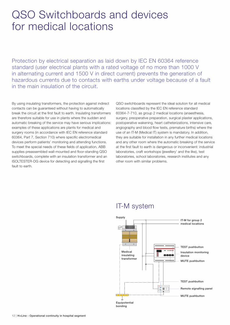
By using insulating transformers, the protection against indirect
contacts can be guaranteed without having to automatically
break the circuit at the first fault to earth. Insulating transformers
are therefore suitable for use in plants where the sudden and
automatic breaking of the service may have serious implications:
examples of these applications are plants for medical and
surgery rooms (in accordance with IEC EN reference standard
60364, Part 7, Section 710) where specific electromedical
devices perform patients’ monitoring and attending functions.
To meet the special needs of these fields of application, ABB
supplies preassembled wall-mounted and floor-standing QSO
switchboards, complete with an insulation transformer and an
ISOLTESTER-DG device for detecting and signalling the first
fault to earth.
Protection by electrical separation as laid down by IEC EN 60364 reference standard (user electrical plants with a rated voltage of no more than 1000 V in alternating current and 1500 V in direct current) prevents the generation of hazardous currents due to contacts with earths under voltage because of a fault in the main insulation of the circuit.
SupplyIT-M for group 2
medical locations
TEST pushbutton
Insulation monitoring
device
MUTE pushbutton
TEST pushbutton
Remote signalling panel
MUTE pushbutton
Equipotential
bonding
Medical
insulating
transformer
IT-M system
QSO switchboards represent the ideal solution for all medical
locations classified by the IEC EN reference standard
60364-7-710, as group 2 medical locations (anaesthesia,
surgery, preoperative preparation, surgical plaster applications,
postoperative wakening, heart catheterizations, intensive care,
angiography and blood flow tests, premature births) where the
use of an IT-M (Medical IT) system is mandatory. In addition,
they are suitable for installation in any further medical locations
and any other room where the automatic breaking of the service
at the first fault to earth is dangerous or inconvenient: industrial
laboratories, craft workshops (jewellery’ and the like), test
laboratories, school laboratories, research institutes and any
other room with similar problems.
QSO Switchboards and devices for medical locations
H+Line - Operational continuity in hospital segment | 13
Protection, control and operational continuity
The new QSO operating theatre switchboards are the ideal solution to supply operating theatres and group 2 medical locations according to the IEC 60364-7-710 reference standard. All the switchboards are wired by ABB, and are equipped with the declaration of conformity which is necessary for the system initial start up, guaranteeing the installer full conformity for plant performance.
Compactness, total protection selectivity and maximum ergonomics and simplicity during maintenance operations make QSO range the most suitable product to guarantee service continuity at medical locations.
14 | H+Line - Operational continuity in hospital segment
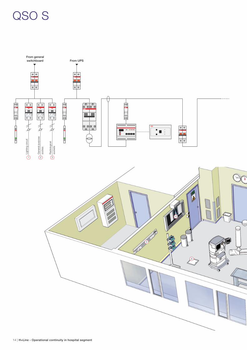
QSO S
9
8
10
1 32
Ligh
ting
circ
uit
Gen
eral
pur
pose
sock
es
Rad
iolo
gica
l
sock
ets
From general switchboard From UPS
H+Line - Operational continuity in hospital segment | 15
1
7
3
5
11
2
4
6
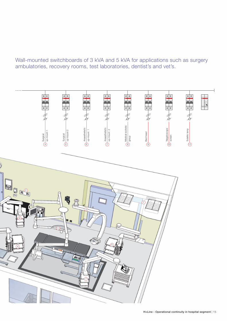
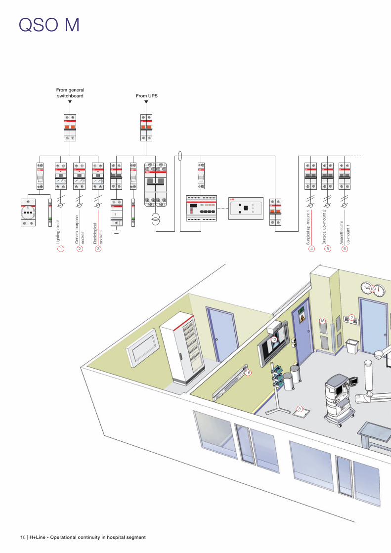
Wall-mounted switchboards of 3 kVA and 5 kVA for applications such as surgery ambulatories, recovery rooms, test laboratories, dentist’s and vet’s.
754 6
Sur
gica
l
up-m
ount
1
Sur
gica
l
up-m
ount
2
Ana
esth
etis
t’s
up-m
ount
1
Ana
esth
etis
t’s
up-m
ount
2
9 118 10
Med
ical
soc
kets
grou
p
Bed
-hea
d
Neg
atos
cope
scre
en
Sci
aliti
c la
mp
16 | H+Line - Operational continuity in hospital segment
2
8
12
13
15
16
QSO M
1 32
Ligh
ting
circ
uit
54 6
Sur
gica
l up-
mou
nt 1
Sur
gica
l up-
mou
nt 2
Ana
esth
etis
t’s
up-m
ount
1
From general switchboard From UPS
Gen
eral
pur
pose
sock
es
Rad
iolo
gica
l
sock
ets
H+Line - Operational continuity in hospital segment | 17
1
7
3
9
5
11
4
10
6 17
14
18
7
Ana
esth
etis
t’s
up-m
ount
2
9 118 10 12
Med
ical
plu
gs
grou
p 1
Med
ical
plu
gs
grou
p 2
Med
ical
plu
gs
grou
p 3
Med
ical
plu
gs
grou
p 4
Neg
atos
cope
scre
en
13 15 1714 16 18
Sto
pwat
ch
Ele
ctric
bed
Res
erve
Bed
-hea
d
Vario
us
Sci
aliti
c
lam
p
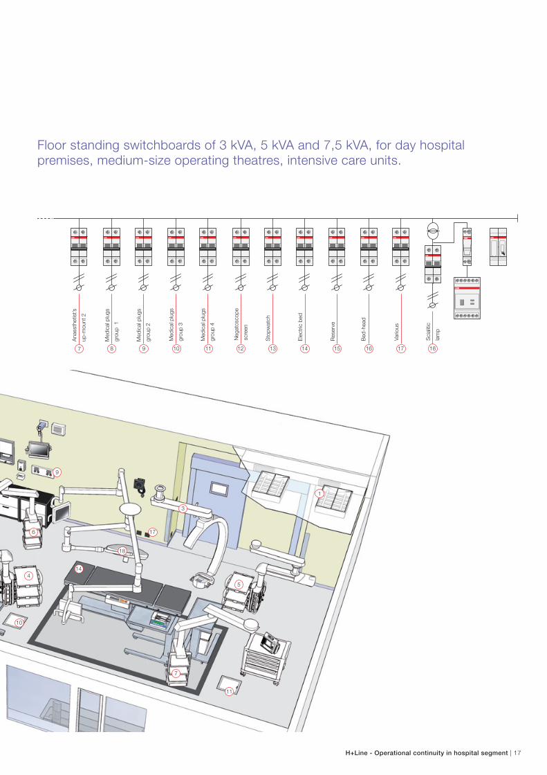
Floor standing switchboards of 3 kVA, 5 kVA and 7,5 kVA, for day hospital premises, medium-size operating theatres, intensive care units.
18 | H+Line - Operational continuity in hospital segment
QSO L
9
2
8
12
15
20
1624
13
1 73 52 4 6
Ligh
ting
circ
uit
Sur
gica
l up-
mou
nt 1
Sur
gica
l up-
mou
nt 2
Ana
esth
etis
t’s
up-m
ount
1
Ana
esth
etis
t’s
up-m
ount
2
From general switchboard From UPS
Gen
eral
pur
pose
sock
es
Rad
iolo
gica
l
sock
ets
H+Line - Operational continuity in hospital segment | 19
1
7
3
5
11
4
10
6
19
15
21
17
23
14
16
22
18
9 118 10 12
Med
ical
plu
gs
grou
p 1
Med
ical
plu
gs
grou
p 2
Med
ical
plu
gs
grou
p 3
Med
ical
plu
gs
grou
p 4
Neg
atos
cope
scre
en
13 1915 2117 23
24
14 2016 2218
Sto
pwat
ch
Mot
oriz
ed d
oor
Sur
gica
l
up-m
ount
mot
or
Ana
esth
etis
t’s
up-m
ount
mot
or
Bed
plu
g
Vario
us
TV a
nd r
adio
plu
gs
Res
erve
Infu
sion
pum
p
Sci
aliti
c la
mp
1
Sci
aliti
c la
mp
2
Loca
l sec
tion
switc
hboa
rd
supp
ly
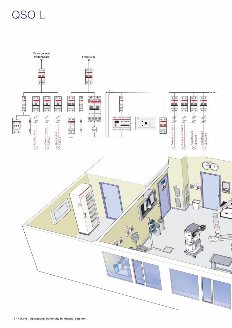
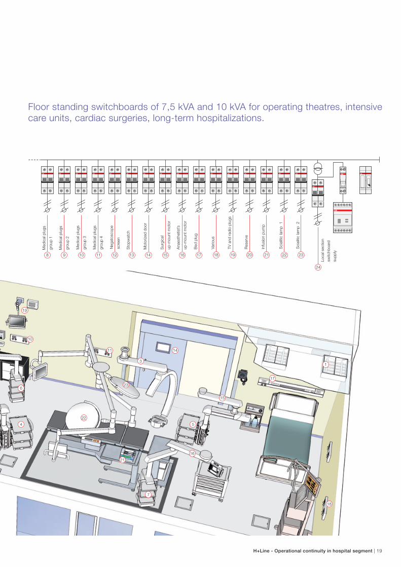
Floor standing switchboards of 7,5 kVA and 10 kVA for operating theatres, intensive care units, cardiac surgeries, long-term hospitalizations.
20 | H+Line - Operational continuity in hospital segment
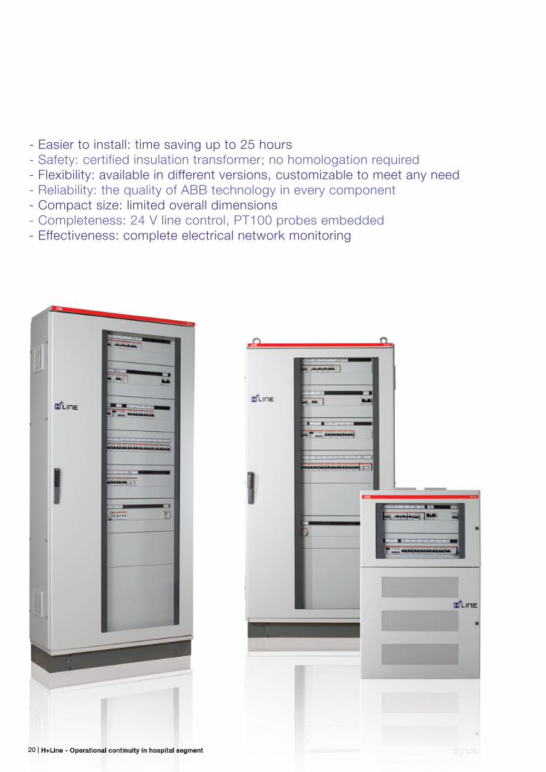
- Easier to install: time saving up to 25 hours- Safety: certified insulation transformer; no homologation required- Flexibility: available in different versions, customizable to meet any need- Reliability: the quality of ABB technology in every component- Compact size: limited overall dimensions- Completeness: 24 V line control, PT100 probes embedded- Effectiveness: complete electrical network monitoring
H+Line - Operational continuity in hospital segment | 21
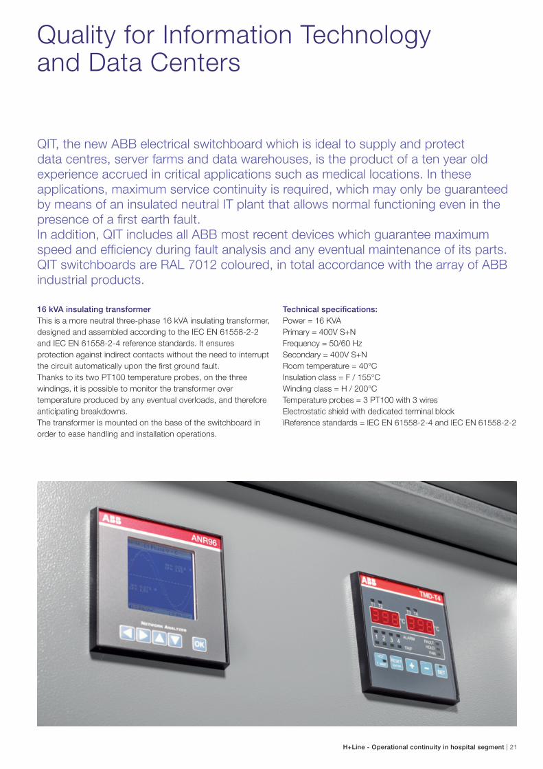
Quality for Information Technology and Data Centers
QIT, the new ABB electrical switchboard which is ideal to supply and protect data centres, server farms and data warehouses, is the product of a ten year old experience accrued in critical applications such as medical locations. In these applications, maximum service continuity is required, which may only be guaranteed by means of an insulated neutral IT plant that allows normal functioning even in the presence of a first earth fault.In addition, QIT includes all ABB most recent devices which guarantee maximum speed and efficiency during fault analysis and any eventual maintenance of its parts. QIT switchboards are RAL 7012 coloured, in total accordance with the array of ABB industrial products.
16 kVA insulating transformer
This is a more neutral three-phase 16 kVA insulating transformer,
designed and assembled according to the IEC EN 61558-2-2
and IEC EN 61558-2-4 reference standards. It ensures
protection against indirect contacts without the need to interrupt
the circuit automatically upon the first ground fault.
Thanks to its two PT100 temperature probes, on the three
windings, it is possible to monitor the transformer over
temperature produced by any eventual overloads, and therefore
anticipating breakdowns.
The transformer is mounted on the base of the switchboard in
order to ease handling and installation operations.
Technical specifications:
Power = 16 KVA
Primary = 400V S+N
Frequency = 50/60 Hz
Secondary = 400V S+N
Room temperature = 40°C
Insulation class = F / 155°C
Winding class = H / 200°C
Temperature probes = 3 PT100 with 3 wires
Electrostatic shield with dedicated terminal block
ìReference standards = IEC EN 61558-2-4 and IEC EN 61558-2-2
22 | H+Line - Operational continuity in hospital segment
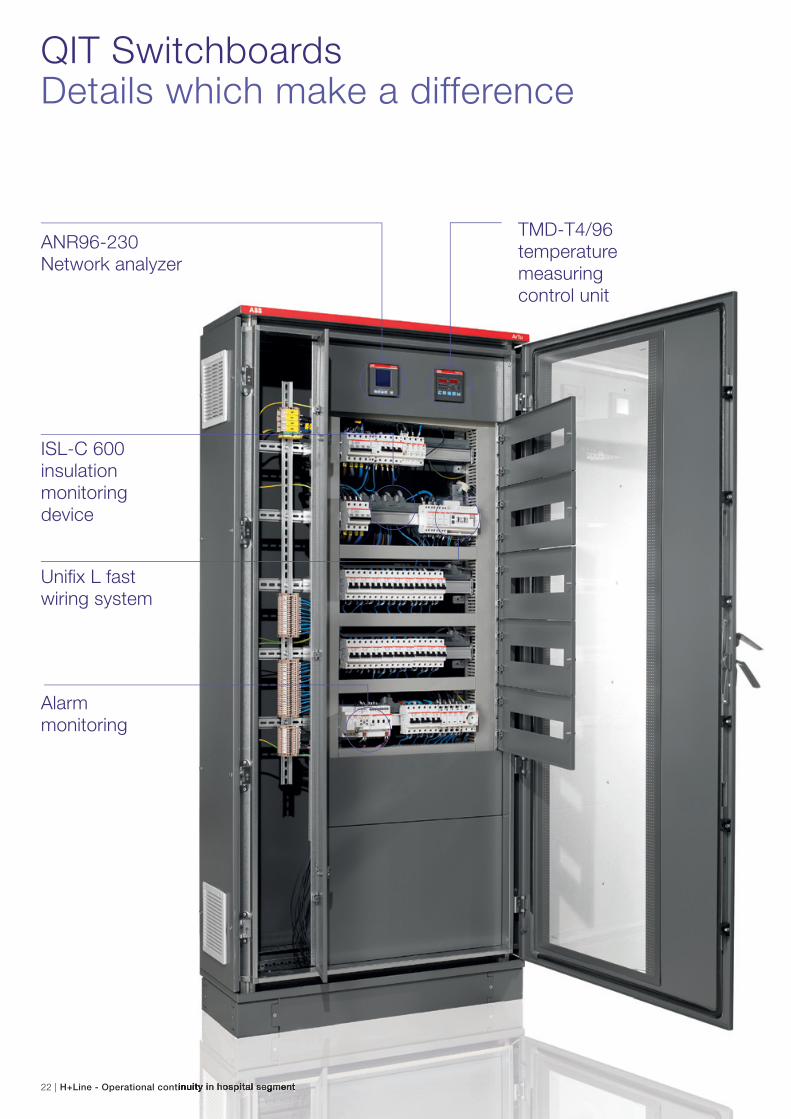
QIT SwitchboardsDetails which make a difference
ANR96-230 Network analyzer
ISL-C 600 insulation monitoring device
Alarm monitoring
TMD-T4/96 temperature measuring control unit
Unifix L fast wiring system
H+Line - Operational continuity in hospital segment | 23
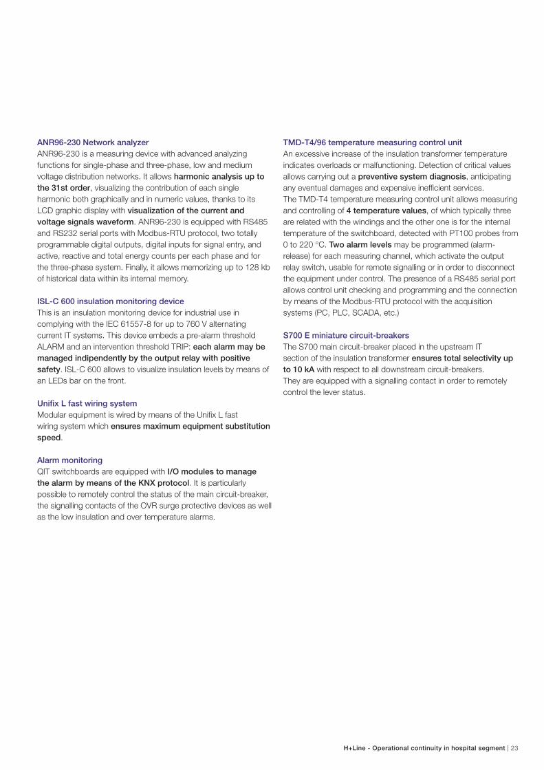
ANR96-230 Network analyzer
ANR96-230 is a measuring device with advanced analyzing
functions for single-phase and three-phase, low and medium
voltage distribution networks. It allows harmonic analysis up to
the 31st order, visualizing the contribution of each single
harmonic both graphically and in numeric values, thanks to its
LCD graphic display with visualization of the current and
voltage signals waveform. ANR96-230 is equipped with RS485
and RS232 serial ports with Modbus-RTU protocol, two totally
programmable digital outputs, digital inputs for signal entry, and
active, reactive and total energy counts per each phase and for
the three-phase system. Finally, it allows memorizing up to 128 kb
of historical data within its internal memory.
ISL-C 600 insulation monitoring device
This is an insulation monitoring device for industrial use in
complying with the IEC 61557-8 for up to 760 V alternating
current IT systems. This device embeds a pre-alarm threshold
ALARM and an intervention threshold TRIP: each alarm may be
managed indipendently by the output relay with positive
safety. ISL-C 600 allows to visualize insulation levels by means of
an LEDs bar on the front.
Unifix L fast wiring system
Modular equipment is wired by means of the Unifix L fast
wiring system which ensures maximum equipment substitution
speed.
Alarm monitoring
QIT switchboards are equipped with I/O modules to manage
the alarm by means of the KNX protocol. It is particularly
possible to remotely control the status of the main circuit-breaker,
the signalling contacts of the OVR surge protective devices as well
as the low insulation and over temperature alarms.
TMD-T4/96 temperature measuring control unit
An excessive increase of the insulation transformer temperature
indicates overloads or malfunctioning. Detection of critical values
allows carrying out a preventive system diagnosis, anticipating
any eventual damages and expensive inefficient services.
The TMD-T4 temperature measuring control unit allows measuring
and controlling of 4 temperature values, of which typically three
are related with the windings and the other one is for the internal
temperature of the switchboard, detected with PT100 probes from
0 to 220 °C. Two alarm levels may be programmed (alarm-
release) for each measuring channel, which activate the output
relay switch, usable for remote signalling or in order to disconnect
the equipment under control. The presence of a RS485 serial port
allows control unit checking and programming and the connection
by means of the Modbus-RTU protocol with the acquisition
systems (PC, PLC, SCADA, etc.)
S700 E miniature circuit-breakers
The S700 main circuit-breaker placed in the upstream IT
section of the insulation transformer ensures total selectivity up
to 10 kA with respect to all downstream circuit-breakers.
They are equipped with a signalling contact in order to remotely
control the lever status.
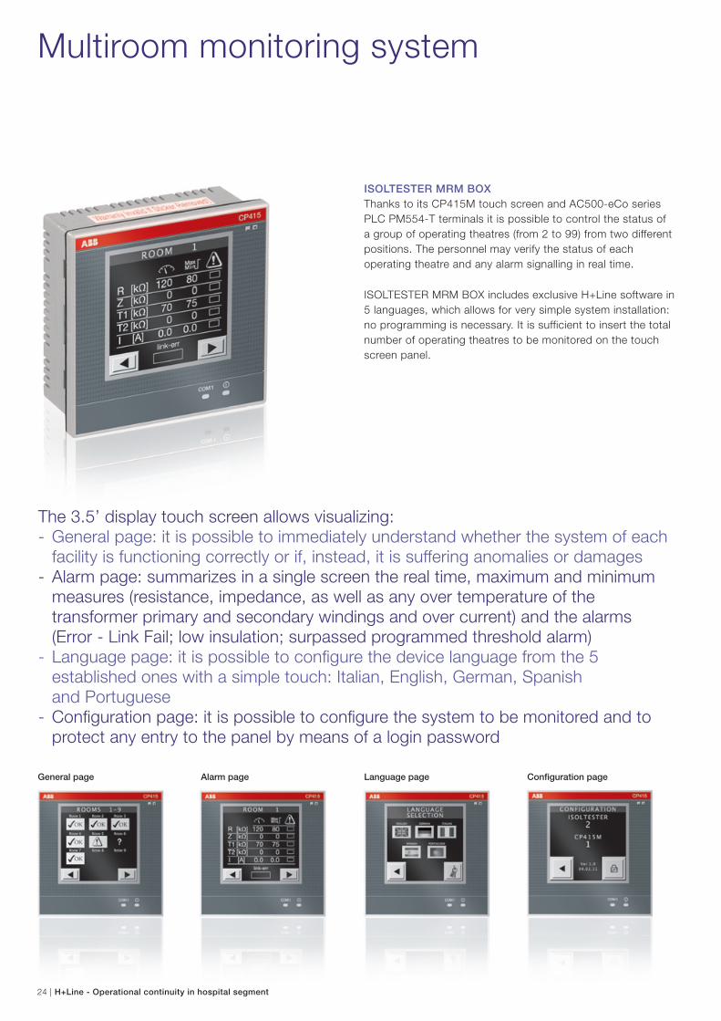
ISOLTESTER MRM BOX
Thanks to its CP415M touch screen and AC500-eCo series
PLC PM554-T terminals it is possible to control the status of
a group of operating theatres (from 2 to 99) from two different
positions. The personnel may verify the status of each
operating theatre and any alarm signalling in real time.
ISOLTESTER MRM BOX includes exclusive H+Line software in
5 languages, which allows for very simple system installation:
no programming is necessary. It is sufficient to insert the total
number of operating theatres to be monitored on the touch
screen panel.
Multiroom monitoring system
The 3.5’ display touch screen allows visualizing:- General page: it is possible to immediately understand whether the system of each
facility is functioning correctly or if, instead, it is suffering anomalies or damages - Alarm page: summarizes in a single screen the real time, maximum and minimum
measures (resistance, impedance, as well as any over temperature of the transformer primary and secondary windings and over current) and the alarms (Error - Link Fail; low insulation; surpassed programmed threshold alarm)
- Language page: it is possible to configure the device language from the 5 established ones with a simple touch: Italian, English, German, Spanish
and Portuguese - Configuration page: it is possible to configure the system to be monitored and to
protect any entry to the panel by means of a login password
General page Alarm page Language page Configuration page
24 | H+Line - Operational continuity in hospital segment
H+Line - Operational continuity in hospital segment | 25
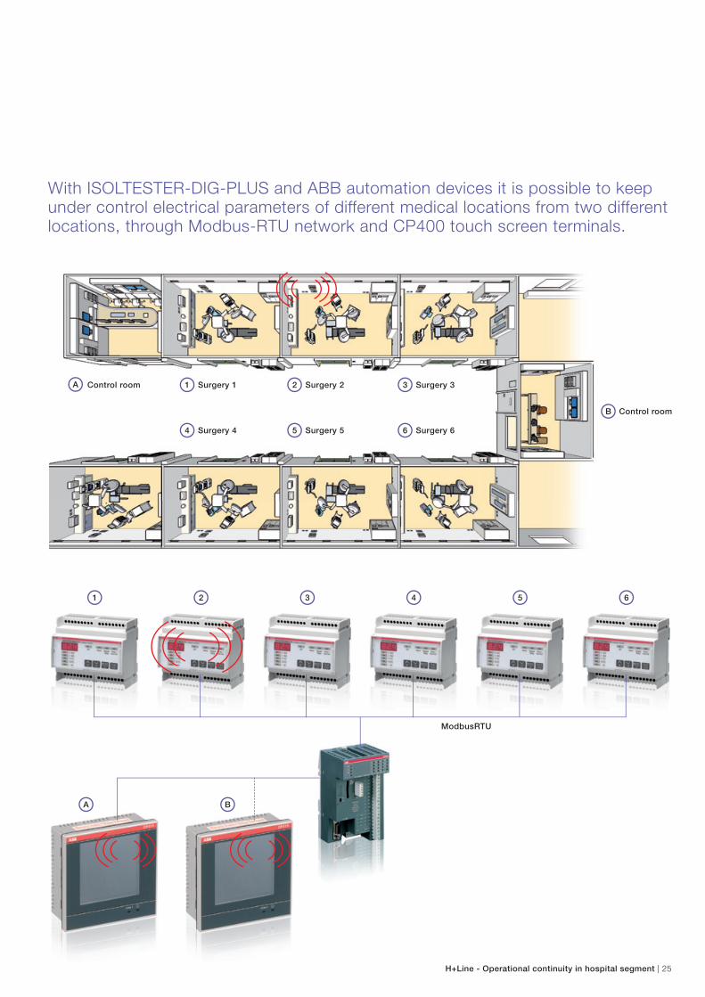
Surgery 11
Surgery 44
Surgery 22
Surgery 55
Surgery 33
Surgery 66
Control roomA
Control roomB
With ISOLTESTER-DIG-PLUS and ABB automation devices it is possible to keep under control electrical parameters of different medical locations from two different locations, through Modbus-RTU network and CP400 touch screen terminals.
ModbusRTU
1
A
2 3 54 6
B
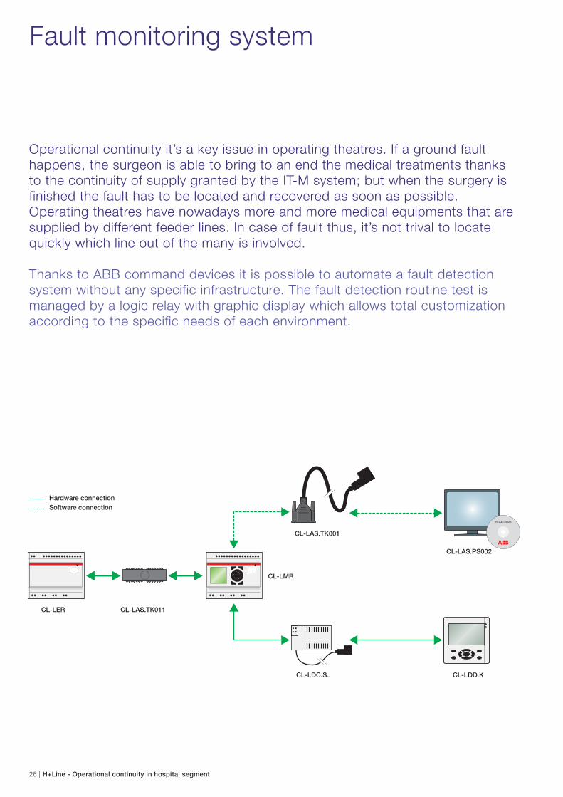
Fault monitoring system
Operational continuity it’s a key issue in operating theatres. If a ground fault happens, the surgeon is able to bring to an end the medical treatments thanks to the continuity of supply granted by the IT-M system; but when the surgery is finished the fault has to be located and recovered as soon as possible.Operating theatres have nowadays more and more medical equipments that are supplied by different feeder lines. In case of fault thus, it’s not trival to locate quickly which line out of the many is involved.
Thanks to ABB command devices it is possible to automate a fault detection system without any specific infrastructure. The fault detection routine test is managed by a logic relay with graphic display which allows total customization according to the specific needs of each environment.
CL-LAS.PS002
CL-LER CL-LAS.TK011
CL-LDC.S..
CL-LAS.TK001
CL-LDD.K
CL-LAS.PS002
CL-LMR
Hardware connectionSoftware connection
26 | H+Line - Operational continuity in hospital segment
H+Line - Operational continuity in hospital segment | 27
CL-LDC.S.. CL-LDD.K
28 | H+Line - Operational continuity in hospital segment
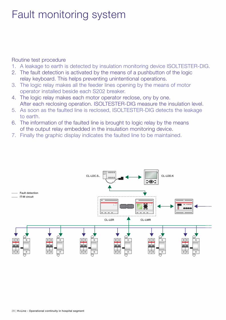
Fault monitoring system
Routine test procedure1. A leakage to earth is detected by insulation monitoring device ISOLTESTER-DIG.2. The fault detection is activated by the means of a pushbutton of the logic relay keyboard. This helps preventing unintentional operations.3. The logic relay makes all the feeder lines opening by the means of motor operator installed beside each S202 breaker.4. The logic relay makes each motor operator reclose, ony by one. After each reclosing operation. ISOLTESTER-DIG measure the insulation level.5. As soon as the faulted line is reclosed, ISOLTESTER-DIG detects the leakage to earth. 6. The information of the faulted line is brought to logic relay by the means of the output relay embedded in the insulation monitoring device.7. Finally the graphic display indicates the faulted line to be maintained.
CL-LER CL-LMR
Fault detectionIT-M circuit
H+Line - Operational continuity in hospital segment | 29
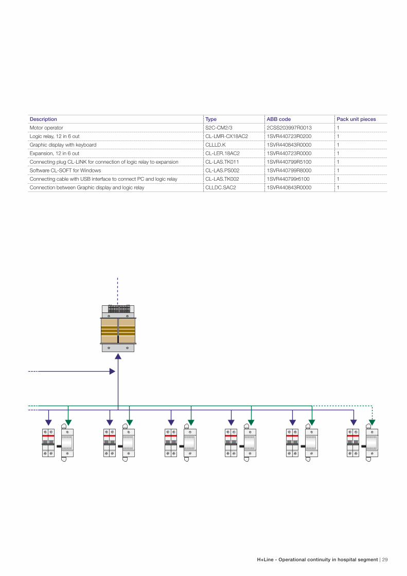
Description Type ABB code Pack unit pieces
Motor operator S2C-CM2/3 2CSS203997R0013 1
Logic relay, 12 in 6 out CL-LMR-CX18AC2 1SVR440723R0200 1
Graphic display with keyboard CLLLD.K 1SVR440843R0000 1
Expansion, 12 in 6 out CL-LER.18AC2 1SVR440723R0000 1
Connecting plug CL-LINK for connection of logic relay to expansion CL-LAS.TK011 1SVR440799R5100 1
Software CL-SOFT for Windows CL-LAS.PS002 1SVR440799R8000 1
Connecting cable with USB interface to connect PC and logic relay CL-LAS.TK002 1SVR440799r6100 1
Connection between Graphic display and logic relay CLLDC.SAC2 1SVR440843R0000 1
30 | H+Line - Operational continuity in hospital segment
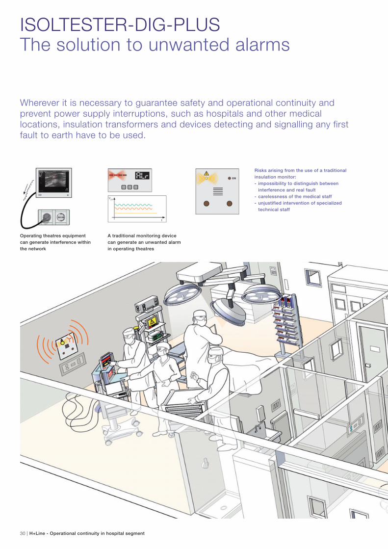
Operating theatres equipment
can generate interference within
the network
A traditional monitoring device
can generate an unwanted alarm
in operating theatres
ISOLTESTER-DIG-PLUSThe solution to unwanted alarms
Wherever it is necessary to guarantee safety and operational continuity and prevent power supply interruptions, such as hospitals and other medical locations, insulation transformers and devices detecting and signalling any first fault to earth have to be used.
Risks arising from the use of a traditional
insulation monitor:
- impossibility to distinguish between
interference and real fault
- carelessness of the medical staff
- unjustified intervention of specialized
technical staff
H+Line - Operational continuity in hospital segment | 31
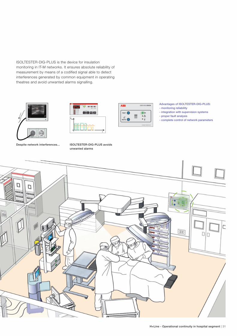
Despite network interferences... ISOLTESTER-DIG-PLUS avoids
unwanted alarms
ISOLTESTER-DIG-PLUS is the device for insulation
monitoring in IT-M networks. It ensures absolute reliability of
measurement by means of a codified signal able to detect
interferences generated by common equipment in operating
theatres and avoid unwanted alarms signalling.
Advantages of ISOLTESTER-DIG-PLUS:
- monitoring reliability
- integration with supervision systems
- proper fault analysis
- complete control of network parameters
32 | H+Line - Operational continuity in hospital segment
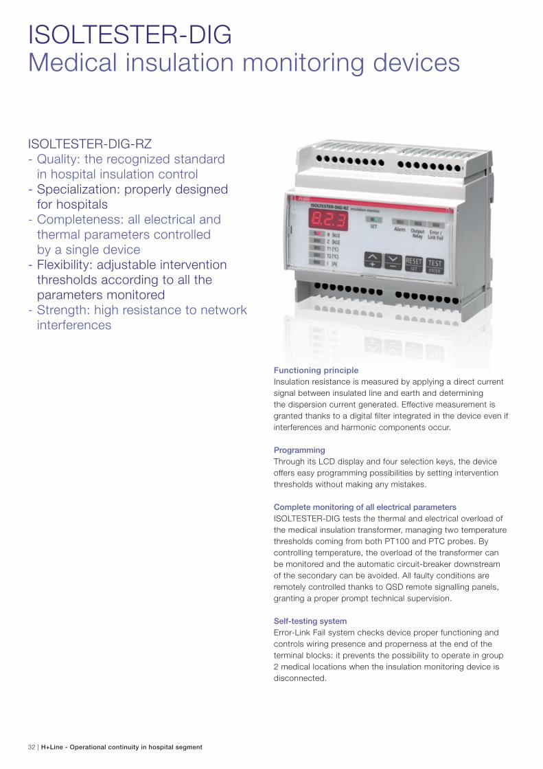
ISOLTESTER-DIGMedical insulation monitoring devices
Functioning principle
Insulation resistance is measured by applying a direct current
signal between insulated line and earth and determining
the dispersion current generated. Effective measurement is
granted thanks to a digital filter integrated in the device even if
interferences and harmonic components occur.
Programming
Through its LCD display and four selection keys, the device
offers easy programming possibilities by setting intervention
thresholds without making any mistakes.
Complete monitoring of all electrical parameters
ISOLTESTER-DIG tests the thermal and electrical overload of
the medical insulation transformer, managing two temperature
thresholds coming from both PT100 and PTC probes. By
controlling temperature, the overload of the transformer can
be monitored and the automatic circuit-breaker downstream
of the secondary can be avoided. All faulty conditions are
remotely controlled thanks to QSD remote signalling panels,
granting a proper prompt technical supervision.
Self-testing system
Error-Link Fail system checks device proper functioning and
controls wiring presence and properness at the end of the
terminal blocks: it prevents the possibility to operate in group
2 medical locations when the insulation monitoring device is
disconnected.
ISOLTESTER-DIG-RZ- Quality: the recognized standard in hospital insulation control- Specialization: properly designed for hospitals- Completeness: all electrical and
thermal parameters controlled by a single device- Flexibility: adjustable intervention
thresholds according to all the parameters monitored
- Strength: high resistance to network interferences
H+Line - Operational continuity in hospital segment | 33
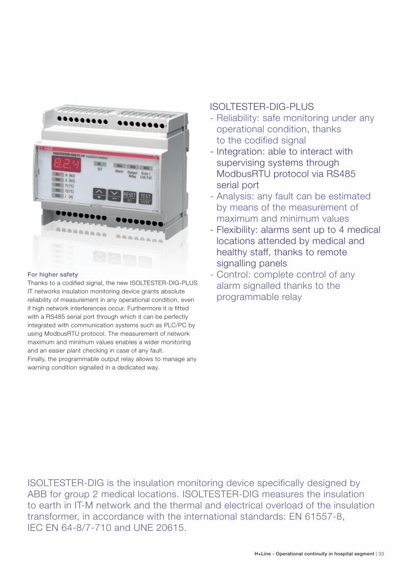
ISOLTESTER-DIG-PLUS- Reliability: safe monitoring under any
operational condition, thanks to the codified signal- Integration: able to interact with
supervising systems through ModbusRTU protocol via RS485
serial port- Analysis: any fault can be estimated
by means of the measurement of maximum and minimum values
- Flexibility: alarms sent up to 4 medical locations attended by medical and healthy staff, thanks to remote signalling panels
- Control: complete control of any alarm signalled thanks to the
programmable relay
ISOLTESTER-DIG is the insulation monitoring device specifically designed by ABB for group 2 medical locations. ISOLTESTER-DIG measures the insulation to earth in IT-M network and the thermal and electrical overload of the insulation transformer, in accordance with the international standards: EN 61557-8, IEC EN 64-8/7-710 and UNE 20615.
For higher safety
Thanks to a codified signal, the new ISOLTESTER-DIG-PLUS
IT networks insulation monitoring device grants absolute
reliability of measurement in any operational condition, even
if high network interferences occur. Furthermore it is fitted
with a RS485 serial port through which it can be perfectly
integrated with communication systems such as PLC/PC by
using ModbusRTU protocol. The measurement of network
maximum and minimum values enables a wider monitoring
and an easier plant checking in case of any fault.
Finally, the programmable output relay allows to manage any
warning condition signalled in a dedicated way.
34 | H+Line - Operational continuity in hospital segment
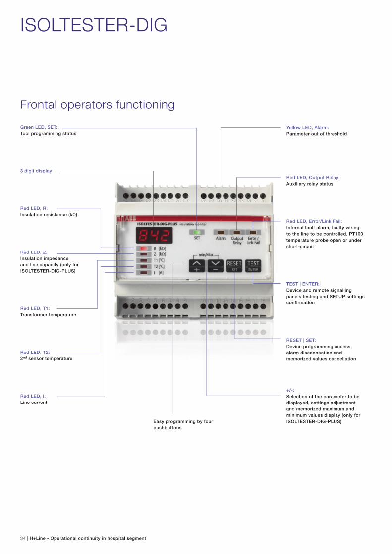
ISOLTESTER-DIG
Frontal operators functioning
Green LED, SET:
Tool programming status
3 digit display
Red LED, R:
Insulation resistance (kΩ)
Red LED, Z:
Insulation impedance
and line capacity (only for
ISOLTESTER-DIG-PLUS)
Red LED, T1:
Transformer temperature
Red LED, T2:
2nd sensor temperature
Red LED, I:
Line current
Yellow LED, Alarm:
Parameter out of threshold
Red LED, Output Relay:
Auxiliary relay status
Red LED, Error/Link Fail:
Internal fault alarm, faulty wiring
to the line to be controlled, PT100
temperature probe open or under
short-circuit
TEST | ENTER:
Device and remote signalling
panels testing and SETUP settings
confirmation
RESET | SET:
Device programming access,
alarm disconnection and
memorized values cancellation
+/-:
Selection of the parameter to be
displayed, settings adjustment
and memorized maximum and
minimum values display (only for
ISOLTESTER-DIG-PLUS)Easy programming by four
pushbuttons
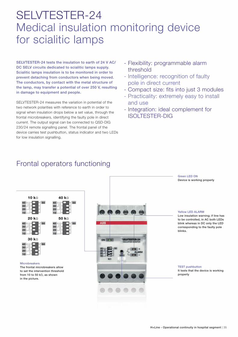
SELVTESTER-24Medical insulation monitoring device for scialitic lamps
SELVTESTER-24 tests the insulation to earth of 24 V AC/
DC SELV circuits dedicated to scialitic lamps supply.
Scialitic lamps insulation is to be monitored in order to
prevent detaching from conductors when being moved.
The conductors, by contact with the metal structure of
the lamp, may transfer a potential of over 250 V, resulting
in damage to equipment and people.
SELVTESTER-24 measures the variation in potential of the
two network polarities with reference to earth in order to
signal when insulation drops below a set value, through the
frontal microbreakers, identifying the faulty pole in direct
current. The output signal can be connected to QSD-DIG
230/24 remote signalling panel. The frontal panel of the
device carries test pushbutton, status indicator and two LEDs
for low insulation signalling.
- Flexibility: programmable alarm threshold
- Intelligence: recognition of faulty pole in direct current- Compact size: fits into just 3 modules- Practicality: extremely easy to install
and use- Integration: ideal complement for
ISOLTESTER-DIG
Frontal operators functioning
Green LED ON
Device is working properly
Yellow LED ALARM
Low insulation warning; if line has
to be controlled, in AC both LEDs
blink whereas in DC only the LED
corresponding to the faulty pole
blinks.
TEST pushbutton
It tests that the device is working
properly
Microbreakers
The frontal microbreakers allow
to set the intervention threshold
from 10 to 50 kΩ, as shown
in the picture.
H+Line - Operational continuity in hospital segment | 35
36 | H+Line - Operational continuity in hospital segment
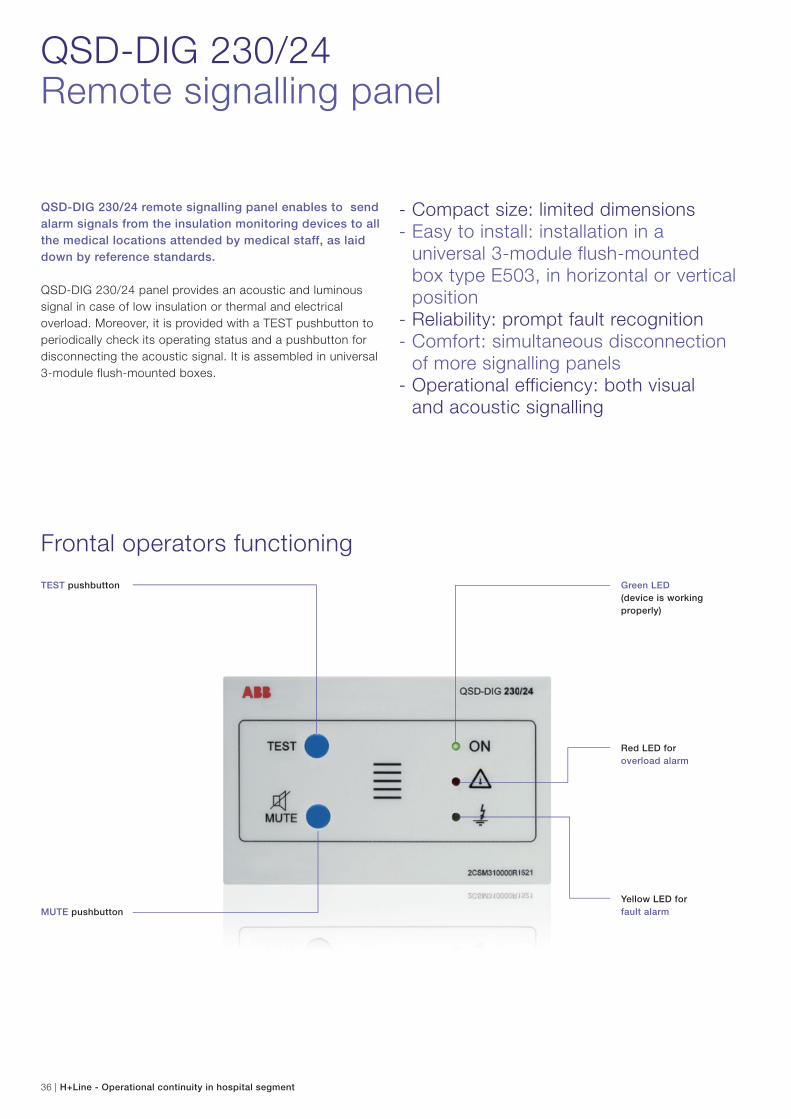
QSD-DIG 230/24Remote signalling panel
QSD-DIG 230/24 remote signalling panel enables to send
alarm signals from the insulation monitoring devices to all
the medical locations attended by medical staff, as laid
down by reference standards.
QSD-DIG 230/24 panel provides an acoustic and luminous
signal in case of low insulation or thermal and electrical
overload. Moreover, it is provided with a TEST pushbutton to
periodically check its operating status and a pushbutton for
disconnecting the acoustic signal. It is assembled in universal
3-module flush-mounted boxes.
- Compact size: limited dimensions- Easy to install: installation in a
universal 3-module flush-mounted box type E503, in horizontal or vertical position
- Reliability: prompt fault recognition- Comfort: simultaneous disconnection
of more signalling panels- Operational efficiency: both visual and acoustic signalling
TEST pushbutton Green LED
(device is working
properly)
Red LED for
overload alarm
MUTE pushbutton
Yellow LED for
fault alarm
Frontal operators functioning
0 230
SCH
0 PC 230
1 2 3 4 5 6
H+Line - Operational continuity in hospital segment | 37
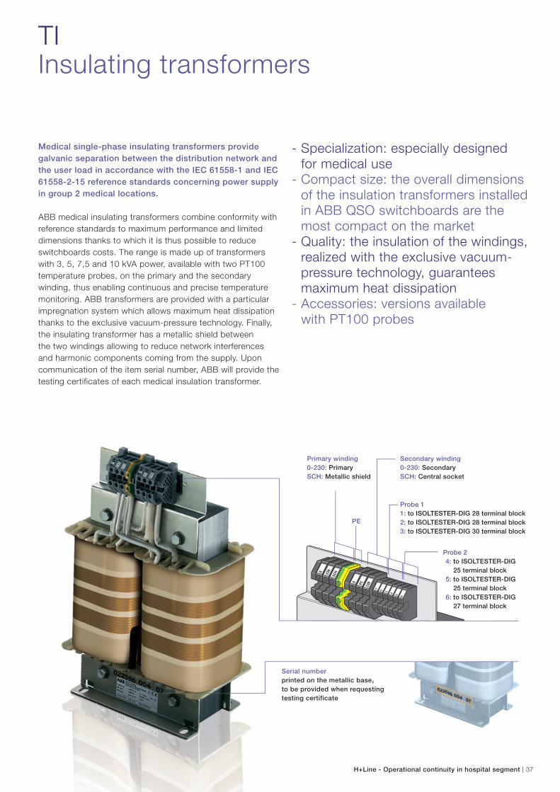
Primary winding
0-230: Primary
SCH: Metallic shield
Secondary winding
0-230: Secondary
SCH: Central socket
PE
Probe 1
1: to ISOLTESTER-DIG 28 terminal block
2: to ISOLTESTER-DIG 28 terminal block
3: to ISOLTESTER-DIG 30 terminal block
Probe 2
4: to ISOLTESTER-DIG
25 terminal block
5: to ISOLTESTER-DIG
25 terminal block
6: to ISOLTESTER-DIG
27 terminal block
TIInsulating transformers
Medical single-phase insulating transformers provide
galvanic separation between the distribution network and
the user load in accordance with the IEC 61558-1 and IEC
61558-2-15 reference standards concerning power supply
in group 2 medical locations.
ABB medical insulating transformers combine conformity with
reference standards to maximum performance and limited
dimensions thanks to which it is thus possible to reduce
switchboards costs. The range is made up of transformers
with 3, 5, 7,5 and 10 kVA power, available with two PT100
temperature probes, on the primary and the secondary
winding, thus enabling continuous and precise temperature
monitoring. ABB transformers are provided with a particular
impregnation system which allows maximum heat dissipation
thanks to the exclusive vacuum-pressure technology. Finally,
the insulating transformer has a metallic shield between
the two windings allowing to reduce network interferences
and harmonic components coming from the supply. Upon
communication of the item serial number, ABB will provide the
testing certificates of each medical insulation transformer.
- Specialization: especially designed for medical use- Compact size: the overall dimensions
of the insulation transformers installed in ABB QSO switchboards are the most compact on the market
- Quality: the insulation of the windings, realized with the exclusive vacuum-pressure technology, guarantees maximum heat dissipation
- Accessories: versions available with PT100 probes
Serial number
printed on the metallic base,
to be provided when requesting
testing certificate
38 | H+Line - Operational continuity in hospital segment
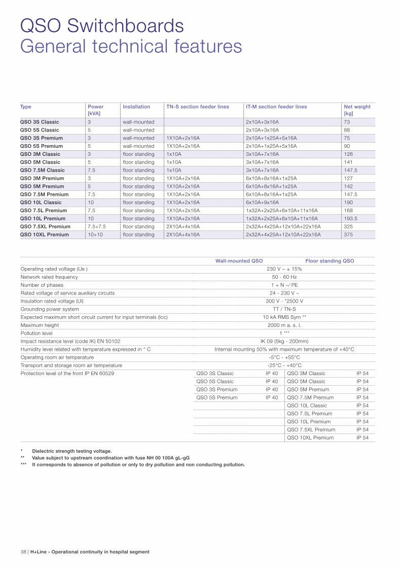
QSO SwitchboardsGeneral technical features
Type Power
[kVA]
Installation TN-S section feeder lines IT-M section feeder lines Net weight
[kg]
QSO 3S Classic 3 wall-mounted 2x10A+3x16A 73
QSO 5S Classic 5 wall-mounted 2x10A+3x16A 88
QSO 3S Premium 3 wall-mounted 1X10A+2x16A 2x10A+1x25A+5x16A 75
QSO 5S Premium 5 wall-mounted 1X10A+2x16A 2x10A+1x25A+5x16A 90
QSO 3M Classic 3 floor standing 1x10A 3x10A+7x16A 126
QSO 5M Classic 5 floor standing 1x10A 3x10A+7x16A 141
QSO 7.5M Classic 7.5 floor standing 1x10A 3x10A+7x16A 147.5
QSO 3M Premium 3 floor standing 1X10A+2x16A 6x10A+8x16A+1x25A 127
QSO 5M Premium 5 floor standing 1X10A+2x16A 6x10A+8x16A+1x25A 142
QSO 7.5M Premium 7.5 floor standing 1X10A+2x16A 6x10A+8x16A+1x25A 147.5
QSO 10L Classic 10 floor standing 1X10A+2x16A 6x10A+9x16A 190
QSO 7.5L Premium 7.5 floor standing 1X10A+2x16A 1x32A+2x25A+6x10A+11x16A 168
QSO 10L Premium 10 floor standing 1X10A+2x16A 1x32A+2x25A+6x10A+11x16A 193.5
QSO 7.5XL Premium 7.5+7.5 floor standing 2X10A+4x16A 2x32A+4x25A+12x10A+22x16A 325
QSO 10XL Premium 10+10 floor standing 2X10A+4x16A 2x32A+4x25A+12x10A+22x16A 375
Wall-mounted QSO Floor standing QSO
Operating rated voltage (Ue ) 230 V ~ ± 15%
Network rated frequency 50 - 60 Hz
Number of phases 1 + N ~⁄ PE
Rated voltage of service auxiliary circuits 24 - 230 V ~
Insulation rated voltage (Ul) 300 V - *2500 V
Grounding power system TT / TN-S
Expected maximum short circuit current for input terminals (Icc) 10 kA RMS Sym **
Maximum height 2000 m a. s. l.
Pollution level 1 ***
Impact resistance level (code IK) EN 50102 IK 09 (5kg - 200mm)
Humidity level related with temperature expressed in ° C Internal mounting 50% with maximum temperature of +40°C
Operating room air temperature -5°C - +55°C
Transport and storage room air temperature -25°C - +40°C
Protection level of the front IP EN 60529 QSO 3S Classic IP 40 QSO 3M Classic IP 54
QSO 5S Classic IP 40 QSO 5M Classic IP 54
QSO 3S Premium IP 40 QSO 5M Premium IP 54
QSO 5S Premium IP 40 QSO 7.5M Premium IP 54
QSO 10L Classic IP 54
QSO 7.5L Premium IP 54
QSO 10L Premium IP 54
QSO 7.5XL Premium IP 54
QSO 10XL Premium IP 54
* Dielectric strength testing voltage.
** Value subject to upstream coordination with fuse NH 00 100A gL-gG
*** It corresponds to absence of pollution or only to dry pollution and non conducting pollution.
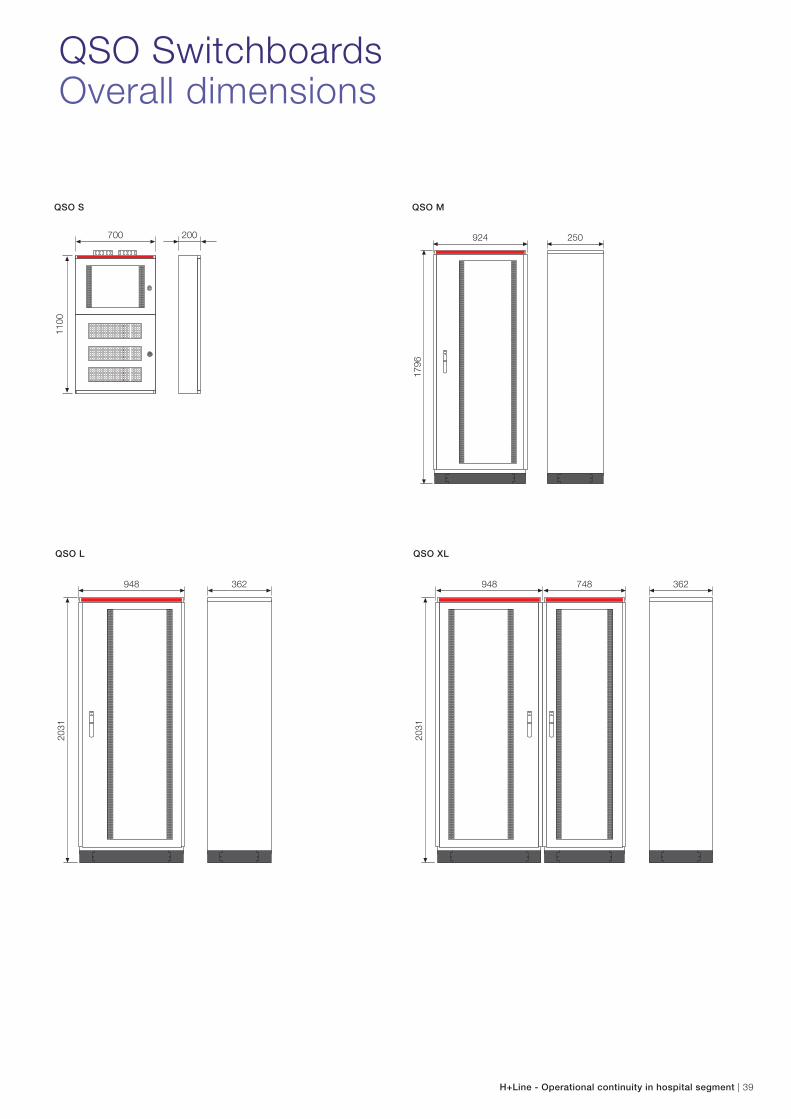
948
2031
362
924
1796
250
1100
700 200
948
2031
362748
H+Line - Operational continuity in hospital segment | 39
QSO SwitchboardsOverall dimensions
QSO M
QSO XL
QSO S
QSO L
Id IdId
E 91hN/32
E 219-D
DS202CC10 A30
DS202CC16 A30
DS202CC16 A30
S202C16
S202C16
E 202/40gE 202/63g
E 91hN/32
E 91hN/32
S702 25A E sel
E 219-D
TI 5-S
CT3/40
S202C16
S202C16
S202C10
S202C16
S202C10
S202C25
E 202/40g
ISOLTESTER-DIG-RZ QSD-DIG 230/24
PT100
40 | H+Line - Operational continuity in hospital segment
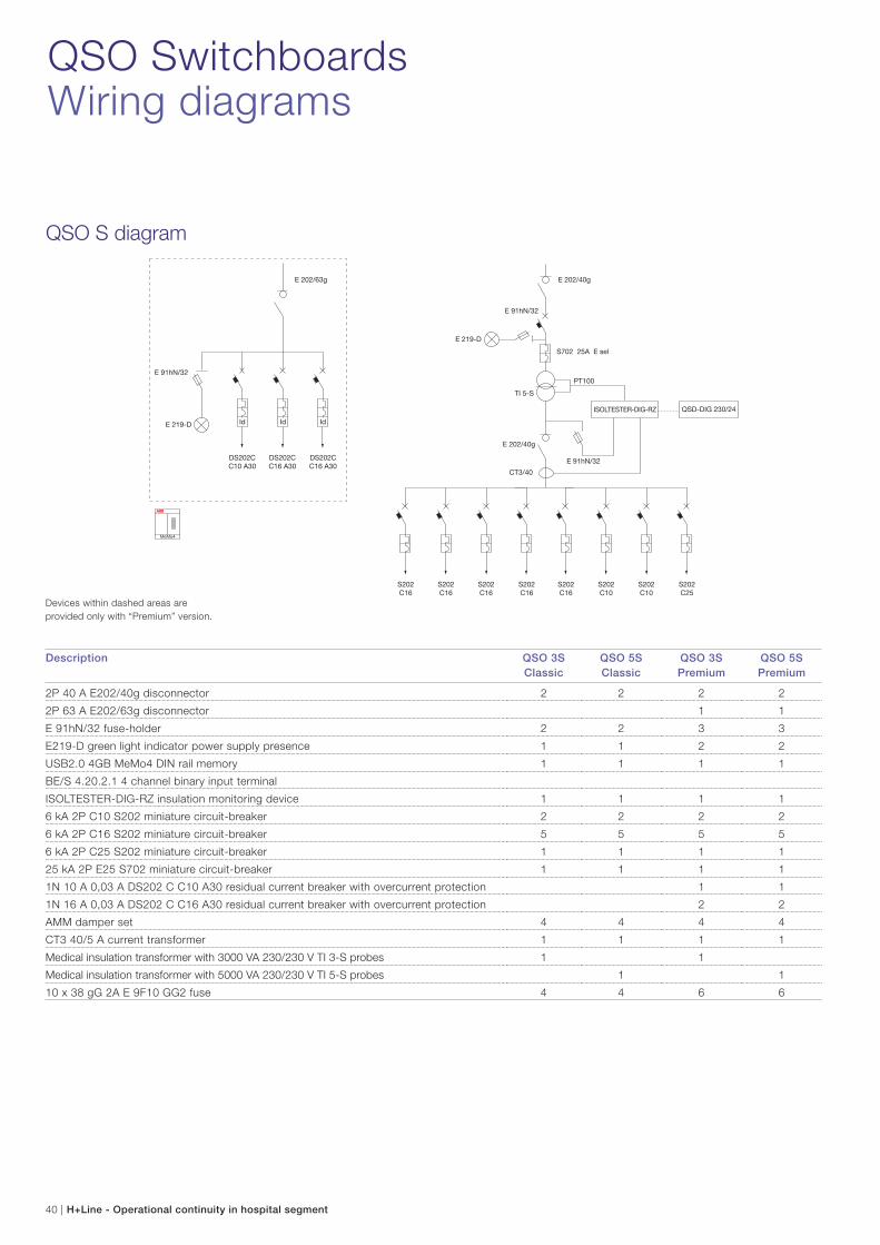
QSO SwitchboardsWiring diagrams
Description QSO 3S
Classic
QSO 5S
Classic
QSO 3S
Premium
QSO 5S
Premium
2P 40 A E202/40g disconnector 2 2 2 2
2P 63 A E202/63g disconnector 1 1
E 91hN/32 fuse-holder 2 2 3 3
E219-D green light indicator power supply presence 1 1 2 2
USB2.0 4GB MeMo4 DIN rail memory 1 1 1 1
BE/S 4.20.2.1 4 channel binary input terminal
ISOLTESTER-DIG-RZ insulation monitoring device 1 1 1 1
6 kA 2P C10 S202 miniature circuit-breaker 2 2 2 2
6 kA 2P C16 S202 miniature circuit-breaker 5 5 5 5
6 kA 2P C25 S202 miniature circuit-breaker 1 1 1 1
25 kA 2P E25 S702 miniature circuit-breaker 1 1 1 1
1N 10 A 0,03 A DS202 C C10 A30 residual current breaker with overcurrent protection 1 1
1N 16 A 0,03 A DS202 C C16 A30 residual current breaker with overcurrent protection 2 2
AMM damper set 4 4 4 4
CT3 40/5 A current transformer 1 1 1 1
Medical insulation transformer with 3000 VA 230/230 V TI 3-S probes 1 1
Medical insulation transformer with 5000 VA 230/230 V TI 5-S probes 1 1
10 x 38 gG 2A E 9F10 GG2 fuse 4 4 6 6
QSO S diagram
Devices within dashed areas are
provided only with “Premium” version.
Id IdId
DS202CC10 A30
DS202CC16 A30
DS202CC16 A30
E 202/63g
S202C16
E 202/63g
E 91hN/32
TM-S 1000/12-24 P
E 91hN/32
E 91hN/32
S702 E selE219-D
TI 3-STI 5-STI 7,5-S
CT3/40
S202C16
S202C16
S202C16
S202C16
S202C16
S202C16
S202C10
S202C10
S202C10
S202C16
S202C25
E 202/40g
E 91hN/32
E 219-D M1175-FL
S202 C10
OVR T2 1N15 275 P
OVR T2 1N15 275 P
S202C10
PT100
SELVTESTER-24
S202 C10
ISOLTESTER-DIG-RZ QSD-DIG 230/24
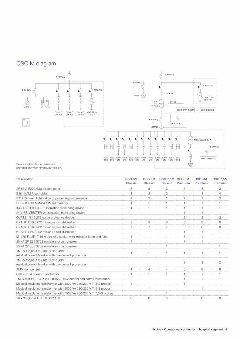
H+Line - Operational continuity in hospital segment | 41
Description QSO 3M
Classic
QSO 5M
Classic
QSO 7,5M
Classic
QSO 3M
Premium
QSO 5M
Premium
QSO 7,5M
Premium
2P 63 A E202/63g disconnector 3 3 3 3 3 3
E 91hN/32 fuse-holder 3 3 3 4 4 4
E219-D green light indicator power supply presence 2 2 2 2 2 2
USB2.0 4GB MeMo4 DIN rail memory 1 1 1 1 1 1
ISOLTESTER-DIG-RZ insulation monitoring device 1 1 1 1 1 1
24 V SELVTESTER-24 insulation monitoring device 1 1 1
OVRT2 1N 15 275 surge protective device 2 2 2
6 kA 2P C10 S202 miniature circuit-breaker 3 3 3 8 8 8
6 kA 2P C16 S202 miniature circuit-breaker 7 7 7 8 8 8
6 kA 2P C25 S202 miniature circuit-breaker 1 1 1
M1175-FL 2P+T 16 A schucko socket with indicator lamp and fuse 1 1 1 1 1 1
25 kA 2P E25 S702 miniature circuit-breaker 1 1 1 1
25 kA 2P E35 S702 miniature circuit-breaker 1 1
1N 10 A 0,03 A DS202 C C10 A30
residual current breaker with overcurrent protection1 1 1 1 1 1
1N 16 A 0,03 A DS202 C C16 A30
residual current breaker with overcurrent protection2 2 2
AMM damper set 4 4 4 8 8 8
CT3 40/5 A current transformer 1 1 1 1 1 1
TM-S 1000/12-24 P. 230-400V S. 24V control and safety transformer 1 1 1
Medical insulating transformer with 3000 VA 230/230 V TI 3-S probes 1 1
Medical insulating transformer with 5000 VA 230/230 V TI 5-S probes 1 1
Medical insulating transformer with 7500 VA 230/230 V TI 7,5-S probes 1 1
10 x 38 gG 2A E 9F10 GG2 fuse 6 6 6 8 8 8
QSO M diagram
Devices within dashed areas are
provided only with “Premium” version.
Id IdId
DS202CC10 A30
DS202CC16 A30
DS202CC16 A30
E 202/63g
S202C16
E 202/63g
E 91hN/32
S202 C10
TM-S 1000/12-24 P
E 91hN/32
E 91hN/32
S702 E selE 219-D
TI 7,5-STI 10-S
CT3/40CT3/50
S202C16
S202C16
S202C16
S202C16
S202C16
S202C16
S202C16
S202C16
S202C10
S202C10
S202C10
S202C10
S202C10
S202C10
S202C25
SELVTESTER-24
E 202/40g
E 91hN/32
E 219-D M1175-FL
S202 C10
OVR T2 1N15 275 P
OVR T2 1N15 275 P
S202C32
S202C16
S202C16
S202C25
S202C25
BE/S4.20.2.1
SA/S4.10.1PT100
ISOLTESTER-DIG-RZ QSD-DIG 230/24
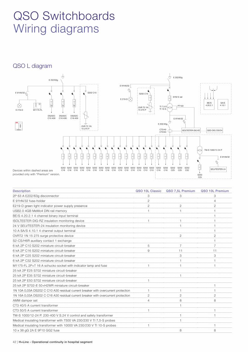
QSO SwitchboardsWiring diagrams
QSO L diagram
42 | H+Line - Operational continuity in hospital segment
Description QSO 10L Classic QSO 7,5L Premium QSO 10L Premium
2P 63 A E202/63g disconnector 3 3 3
E 91hN/32 fuse-holder 2 4
E219-D green light indicator power supply presence 2 2 2
USB2.0 4GB MeMo4 DIN rail memory 1 1 1
BE/S 4.20.2.1 4 channel binary input terminal 1
ISOLTESTER-DIG-RZ insulation monitoring device 1 1 1
24 V SELVTESTER-24 insulation monitoring device 1 1
10 A SA/S 4.10.1 4 channel output terminal 1
OVRT2 1N 15 275 surge protective device 2 2
S2-CS/H6R auxiliary contact 1 exchange 1
6 kA 2P C10 S202 miniature circuit-breaker 5 7 7
6 kA 2P C16 S202 miniature circuit-breaker 9 11 11
6 kA 2P C25 S202 miniature circuit-breaker 3 3
6 kA 2P C32 S202 miniature circuit-breaker 1 1
M1175-FL 2P+T 16 A schucko socket with indicator lamp and fuse 1 1 1
25 kA 2P E25 S702 miniature circuit-breaker
25 kA 2P E35 S702 miniature circuit-breaker 1
25 kA 2P E50 S702 miniature circuit-breaker 1
25 kA 2P S702-E 50+H2WR miniature circuit-breaker 1
1N 10A 0,03A DS202 C C10 A30 residual current breaker with overcurrent protection 1 1 1
1N 16A 0,03A DS202 C C16 A30 residual current breaker with overcurrent protection 2 2 2
AMM damper set 4 8 8
CT3 40/5 A current transformer 1
CT3 50/5 A current transformer 1 1
TM-S 1000/12-24 P. 230-400 V S.24 V control and safety transformer 1 1
Medical insulating transformer with 7500 VA 230/230 V TI 7,5-S probes 1
Medical insulating transformer with 10000 VA 230/230 V TI 10-S probes 1 1
10 x 38 gG 2A E 9F10 GG2 fuse 8 8
Devices within dashed areas are
provided only with “Premium” version.
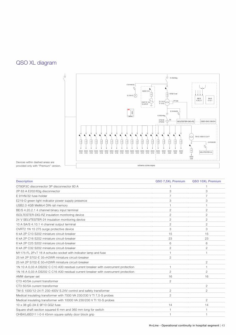
QSO XL diagram
schema come sopra
S202C16
E 202/63g
E 91hN/32
S202 C10
TM-S 1000/12-24 P
E 91hN/32
E 91hN/32
S702 E selE 219-D
TI 7,5-STI 10-S
CT3/40CT3/50
S202C16
S202C16
S202C16
S202C16
S202C16
S202C16
S202C16
S202C16
S202C10
S202C10
S202C10
S202C10
S202C10
S202C10
S202C25
SELVTESTER-24
E 202/40g
OVR T2 1N15 275 P
S202C32
S202C16
S202C16
S202C25
S202C25
BE/S4.20.2.1
SA/S4.10.1PT100
TAISOLTESTER-DIG-RZ QSD-DIG 230/24
H+Line - Operational continuity in hospital segment | 43
Description QSO 7,5XL Premium QSO 10XL Premium
OT80F3C disconnector 3P disconnector 80 A 1 1
2P 63 A E202/63g disconnector 3 3
E 91hN/32 fuse-holder 7 7
E219-D green light indicator power supply presence 3 3
USB2.0 4GB MeMo4 DIN rail memory 1 1
BE/S 4.20.2.1 4 channel binary input terminal 2 2
ISOLTESTER-DIG-RZ insulation monitoring device 2 2
24 V SELVTESTER-24 insulation monitoring device 2 2
10 A SA/S 4.10.1 4 channel output terminal 2 2
OVRT2 1N 15 275 surge protective device 3 3
6 kA 2P C10 S202 miniature circuit-breaker 15 15
6 kA 2P C16 S202 miniature circuit-breaker 23 23
6 kA 2P C25 S202 miniature circuit-breaker 6 6
6 kA 2P C32 S202 miniature circuit-breaker 2 2
M1175-FL 2P+T 16 A schucko socket with indicator lamp and fuse 1 1
25 kA 2P S702-E 35+H2WR miniature circuit-breaker 2
25 kA 2P S702-E 50+H2WR miniature circuit-breaker 2
1N 10 A 0,03 A DS202 C C10 A30 residual current breaker with overcurrent protection 1 1
1N 16 A 0,03 A DS202 C C16 A30 residual current breaker with overcurrent protection 2 2
AMM damper set 16 16
CT3 40/5A current transformer 2
CT3 50/5A current transformer 2
TM-S 1000/12-24 P. 230-400V S.24V control and safety transformer 2 2
Medical insulating transformer with 7500 VA 230/230 V TI 7,5-S probes 2
Medical insulating transformer with 10000 VA 230/230 V TI 10-S probes 2
10 x 38 gG 2A E 9F10 GG2 fuse 14 14
Square shaft section squared 6 mm and 360 mm long for switch 1 1
OHB45J6E011 I-0-II 45mm square safety door block grip 1 1
Devices within dashed areas are
provided only with “Premium” version.
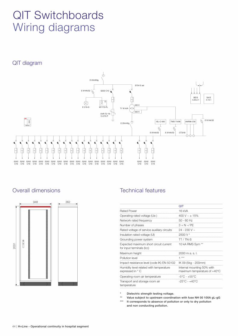
QIT SwitchboardsWiring diagrams
Overall dimensions Technical features
QIT diagram
S202C16
S202C16
S202C16
S202C16
S202C16
S202C16
S202C16
S202C16
S202C16
S202C16
S202C16
S202C16
S202C16
S202C16
S202C16
S202C16
S202C16
S202C16
E 204/63g
E 204/40g
S202 C10
OVR T2 1N15 275 P
E 91hN/32
E 91hN/32
E 91hN/32
E 91hN/32 CT3/40
E 219-D M1175-FL
S704 E sel
TI 16 kVA
400 V
400 V
ISL-C 600 TMD-T4/96 ANR96-230
S202C10
S202C10
S202C10
BE/S4.20.2.1
SA/S4.10.1
948
2031
362
44 | H+Line - Operational continuity in hospital segment
QIT
Rated Power 16 kVA
Operating rated voltage (Ue ) 400 V ~ ± 15%
Network rated frequency 50 - 60 Hz
Number of phases 3 + N ~⁄ PE
Rated voltage of service auxiliary circuits 24 - 230 V ~
Insulation rated voltage (Ul) 2500 V *
Grounding power system TT / TN-S
Expected maximum short circuit current
for input terminals (Icc)
10 kA RMS Sym **
Maximum height 2000 m a. s. l.
Pollution level 1 ***
Impact resistance level (code IK) EN 50102 IK 09 (5kg - 200mm)
Humidity level related with temperature
expressed in ° C
Internal mounting 50% with
maximum temperature of +40°C
Operating room air temperature -5°C - +55°C
Transport and storage room air
temperature
-25°C - +40°C
* Dielectric strength testing voltage.
** Value subject to upstream coordination with fuse NH 00 100A gL-gG
*** It corresponds to absence of pollution or only to dry pollution
and non conducting pollution.
H+Line - Operational continuity in hospital segment | 45
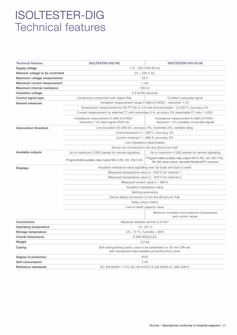
ISOLTESTER-DIGTechnical features
Technical features ISOLTESTER-DIG-RZ ISOLTESTER-DIG-PLUS
Supply voltage 110 - 230 V/50-60 Hz
Network voltage to be controlled 24 ÷ 230 V AC
Maximum voltage measurement 24 V
Maximum current measurement 1 mA
Maximum internal resistance 100 kΩ
Insulation voltage 2,5 kV/60 seconds
Control signal type Continuous component with digital filter Codified composite signal
Sensed measures Insulation measurement range 0÷999 kΩ/HIGH – resolution 1 kΩ
Temperature measurement by Rd PT100 or 2/3-wire thermal-probe – 0÷250°C, accuracy 2%
Current measurement by external CT with secondary 5 A, accuracy 2% (selectable CT ratio 1÷200)
Impedance measurement 0÷999 kΩ/HIGH -
resolution 1 kΩ (test signal 2500 Hz)
Impedance measurement 0÷999 kΩ/HIGH -
resolution 1 kΩ (variable composite signal)
Intervention threshold Low insulation 50÷500 kΩ, accuracy 5%, hysteresis 5%, settable delay
Overtemperature 0 ÷ 200°C, accuracy 2%
Current overload 1 ÷ 999 A, accuracy 2%
Low impedance (deactivable)
Device not connected to the line (Error/Link-Fail)
Available outputs Up to maximum 2 QSO panels for remote signalling Up to maximum 4 QSO panels for remote signalling
Programmable auxiliary relay output NA-C-NC, 5A, 250 V ACProgrammable auxiliary relay output NA-C-NC, 5A, 250 V AC,
RS 485 serial output, standard ModbusRTU protocol
Displays Insulation resistance value signalling over full scale and fault to earth
Measured temperature value 0 ÷ 200°C for channel 1
Measured temperature value 0 ÷ 200°C for channel 2
Measured current value 0 ÷ 999 A
Insulation impedance value
Setting parameters
Device failing connection to the line (Error/Link-Fail)
Relay output status
Line-to-earth capacity value
Minimum insulation and maximum temperature
and current values
Connections Maximum linkable section 2,5 mm2
Operating temperature -10...60 °C
Storage temperature -25...70 °C, humidity < 90%
Overall dimensions 6 DIN MODULES
Weight 0,5 kg
Casing Self-extinguishing plastic case to be assembled on 35 mm DIN rail,
with transparent lead-sealable protective front cover
Degree of protection IP20
Self-consumption 5 VA
Reference standards IEC EN 60364-7-710, IEC EN 61557-8, EN 60255-6, UNE 20615
19 20 21 22 23 24 25 26 27 28 29 30 31 32 33 34 35 36
1 2 3 4 5 6 7 8 9 10 11 12 13 14 15 16 17 18
RS485(only PLUS
version)
T.A. .../5 TT AOut
Checkingfaulty
connectionto the line
Insulation monitoring QSD-DIG 230/24
ISOLTESTER-DIG-RZLLISOLTESTER-DIG-PLUSLL
V aux.*115 V 115 V
1 2 3 4 5 6 7 8 9 10 11
QSD-DIG 230/24
V aux. 230 V AC
Insulation transformer
IT-M
C.T.
Loads
To o
ther
QSD
-DIG
1 2 3 4
V aux.*115 V 115 V
V aux. 115 V AC
PE
PCCL
N
SS
PT100 PT1002 1
19 20 21 22 23 24 25 26 27 28 29 30 31 32 33 34 35 36
1 2 3 4 5 6 7 8 9 10 11 12 13 14 15 16 17 18
RS485 T.A. .../5TT A
Out.
QSD-DIG 230/24
ISOLTESTER-DIG-RZLLISOLTESTER-DIG-PLUSLL
V aux.*115 V 115 V
1 2 3 4 5 6 7 8 9 10 11
QSD-DIG 230/24
V aux. 230 V AC
Insulation transformer
IT-M
PE
N
L1
SS
L3
L2
PT100 PT1002 1
(only PLUSversion)
Checkingfaulty
connectionto the line
Insulationmonitoring
Loads
To o
ther
QSD
-DIG
19 20 21 22 23 24 25 26 27 28 29 30 31 32 33 34 35 36
1 2 3 4 5 6 7 8 9 10 11 12 13 14 15 16 17 18
RS485
PT100 PT1002 1 T.A. .../5 TT A
Out
QSD-DIG 230/24
ISOLTESTER-DIG-RZLLISOLTESTER-DIG-PLUSLL
V aux.*115 V 115 V
1 2 3 4 5 6 7 8 9 10 11
QSD-DIG 230/24
V aux. 230 V AC
IT-M
Insulation transformer without central socket
C.T.
PE
L
N
SS
(only PLUSversion)
Checkingfaulty
connectionto the line
Insulation monitoring
Loads
To o
ther
QSD
-DIG
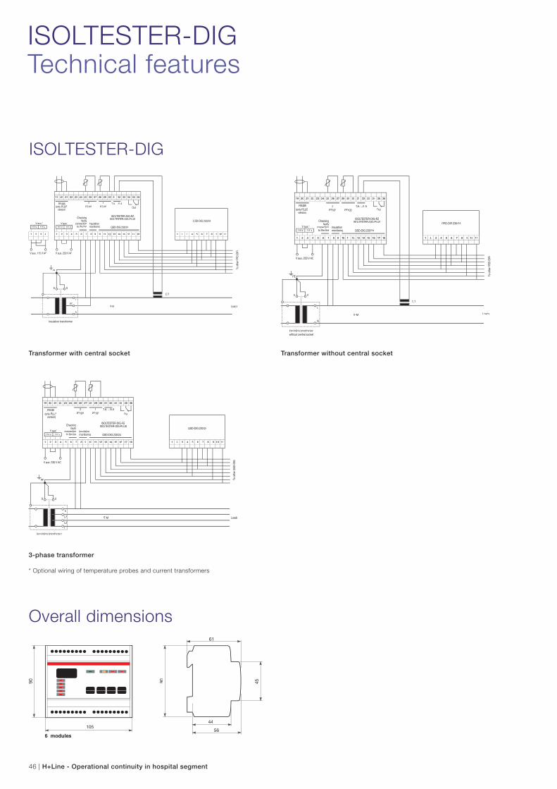
46 | H+Line - Operational continuity in hospital segment
ISOLTESTER-DIG
* Optional wiring of temperature probes and current transformers
Transformer with central socket Transformer without central socket
3-phase transformer
Overall dimensions
ISOLTESTER-DIGTechnical features
Insulation transformer
IT-M Loads
To o
ther
QSD
-230
/24-
C
PE
L(+)
N(-)
SS
1 2 3 C1 C2 C3 C4 X Y Z
QSD-DIG 230/24-C
1 2 3 4 5 6 7 8 9 10 11
SELVTESTER-24
44
58
85,5
52,5
4585,5
H+Line - Operational continuity in hospital segment | 47
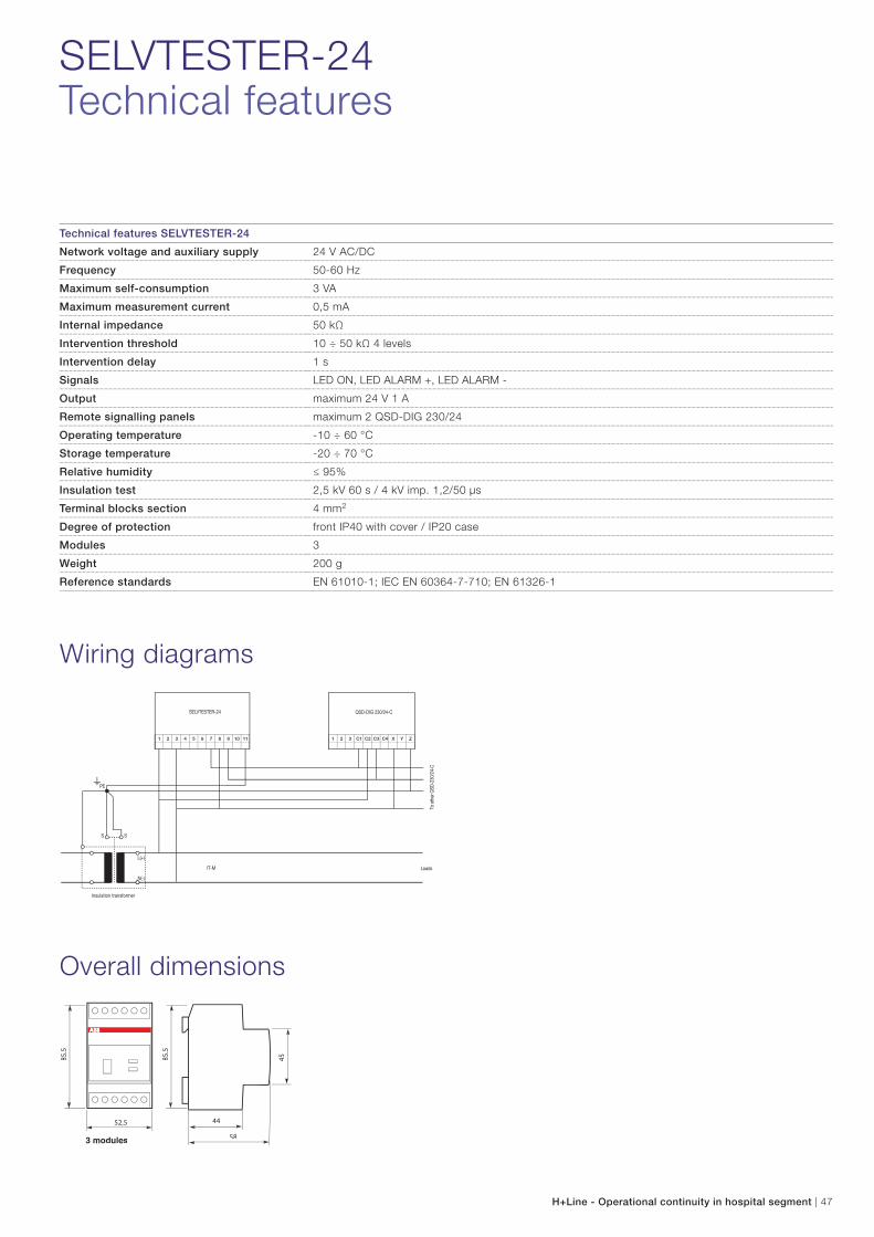
Wiring diagrams
Overall dimensions
Technical features SELVTESTER-24
Network voltage and auxiliary supply 24 V AC/DC
Frequency 50-60 Hz
Maximum self-consumption 3 VA
Maximum measurement current 0,5 mA
Internal impedance 50 kΩ
Intervention threshold 10 ÷ 50 kΩ 4 levels
Intervention delay 1 s
Signals LED ON, LED ALARM +, LED ALARM -
Output maximum 24 V 1 A
Remote signalling panels maximum 2 QSD-DIG 230/24
Operating temperature -10 ÷ 60 °C
Storage temperature -20 ÷ 70 °C
Relative humidity ≤ 95%
Insulation test 2,5 kV 60 s / 4 kV imp. 1,2/50 μs
Terminal blocks section 4 mm2
Degree of protection front IP40 with cover / IP20 case
Modules 3
Weight 200 g
Reference standards EN 61010-1; IEC EN 60364-7-710; EN 61326-1
SELVTESTER-24Technical features

19 20 21 22 23 24 25 26 27 28 29 30 31 32 33 34 35 36
1 2 3 4 5 6 7 8 9 10 11 12 13 14 15 16 17 18
RS485(only PLUS
version)
T.A. .../5TT AOut
Checkingfaulty
connectionto the line
Insulation monitoring QSD-DIG 230/24
ISOLTESTER-DIG-RZLLISOLTESTER-DIG-PLUSLL
V aux.*115 V 115 V
1 2 3 4 5 6 7 8 9 10 11
QSD-DIG 230/24
V aux. 230 V AC
Insulation transformer
IT-M
C.T.
Loads
To o
ther
QSD
-DIG
1 2 3 4
V aux.*115 V 115 V
V aux. 115 V AC
PE
PCCL
N
SS
PT100 PT1002 1
LF-PE
1 2 3 4 5 6 7 82 3 4 5 6 7 9 10 11 12 13 14 15 16 17 18LF-L VC-L VC-PEEAUX-L11 AUX-011 COM-
PV-PFAULTT
Vaux:* CheckingLink-Fail
Insulationmonitoring
Remotecontrol panel
19 20 21 22 23 24 25 26 27 28 29 30 31 32 33 34 35 36
Out
ISOLTESTER-C
1 2 3 43 5 6 7 8 9TEST+TEST-
10 11ACKACUS OVER COM-
PV-P FAULTT
QSD-DIG 230/24
PE
PC
SS
IT-M Loads
Vaux: 230 V AC
230V
L
N
To otherQSD-DIG 230/24
COM-SS
F-SS
TEST-SSR-
NONOR-CC
R-NCNC
Insulation transformer
COM-P2ULTLL 2 COM-P1V-P1 FAULTLL 1ACUS OP-VS-FS-MOC ACK
1 2 3 4 5 6 7 83 4 5 6 7 9PE
10 11V-
SELVTESTER-2LL 4
V+
PE
SS
IT-M Loads
Insulation transformer
L(+)
N(-)
QSD-DIG 230/24
1 2 3 4 5 6 7 8 92 3 4 5 6 7 8
To otherQSD-DIG 230/24
OUT-UUNOO
OUT-UUNCC
OUT-UUCC
10 11TEST++TEST-SSACKACUS OVER COM
-PV-P FAULTLLCOM-
SSF-SS
TEST-SSSS
48 | H+Line - Operational continuity in hospital segment
QSD-DIG 230/24 Remote signalling panelsTechnical features
Technical features QSD-DIG 230/24
Signals Green LED NETWORK; Red LED overload ALARM; Yellow LED FAULT ALARM; Low insulation;
Acoustic signaller; Emission 2400 Hz; Intermittence 2 Hz dB
Pushbuttons Testing (TEST), acoustic disconnection (MUTE)
Terminal blocks section 2,5 mm2
Degree of protection IP30
Installation E503universal 3-module flush-mounted box
Weight 200 g
Operating temperature -10 ÷ 60 °C, maximum humidity 95%
Storage temperature -25 ÷ +80 °C
Insulation 2.500 V rms 50 Hz for 60 s
Connection UTP cable (recommended)
Cable minimum section 0,35 mm² (maximum 300 m)
Reference standards IEC-EN 61010-1, IEC EN 61557-8, IEC EN 60364-7-710, UNE 20615, IEC EN 61326-1
Wiring diagrams
Overall dimensions
ISOLTESTER-DIG SELVTESTER-24
ISOLTESTER-C
QSD-DIG 230/24
ISOLTESTER-RZ
121
7817
55
17
55
121
78
QSD-DIG 230/24 V
H+Line - Operational continuity in hospital segment | 49
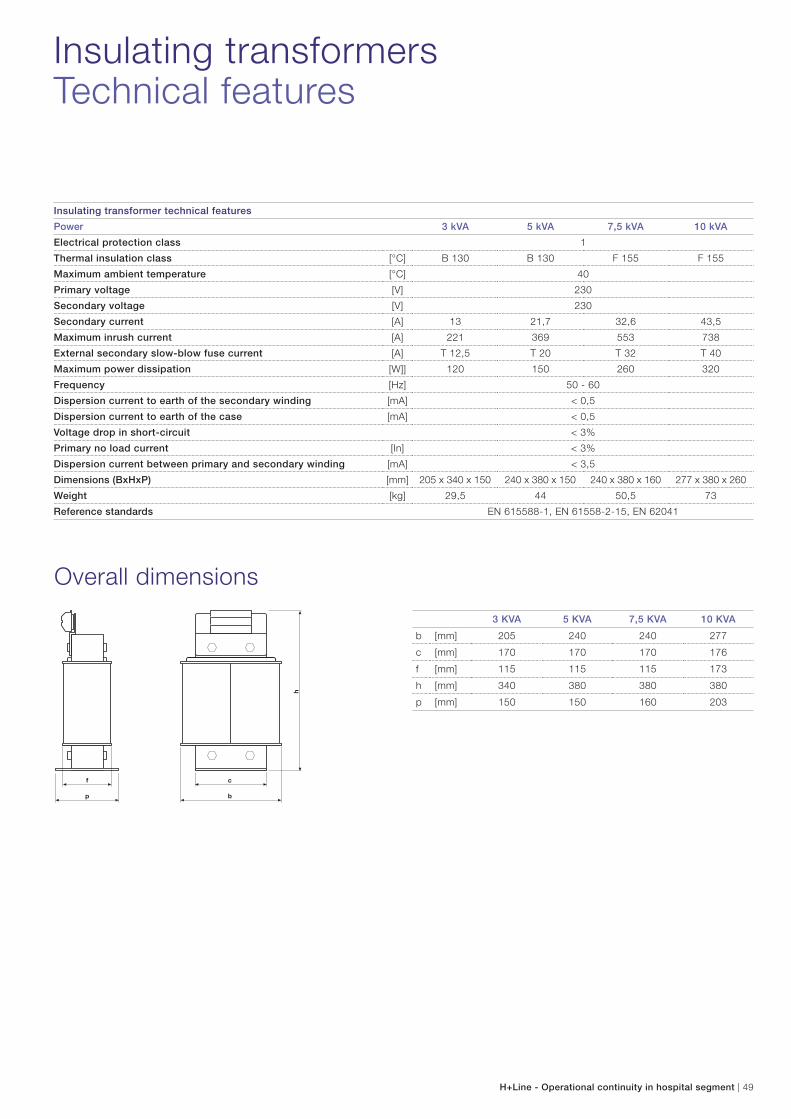
Insulating transformer technical features
Power 3 kVA 5 kVA 7,5 kVA 10 kVA
Electrical protection class 1
Thermal insulation class [°C] B 130 B 130 F 155 F 155
Maximum ambient temperature [°C] 40
Primary voltage [V] 230
Secondary voltage [V] 230
Secondary current [A] 13 21,7 32,6 43,5
Maximum inrush current [A] 221 369 553 738
External secondary slow-blow fuse current [A] T 12,5 T 20 T 32 T 40
Maximum power dissipation [W]] 120 150 260 320
Frequency [Hz] 50 - 60
Dispersion current to earth of the secondary winding [mA] < 0,5
Dispersion current to earth of the case [mA] < 0,5
Voltage drop in short-circuit < 3%
Primary no load current [In] < 3%
Dispersion current between primary and secondary winding [mA] < 3,5
Dimensions (BxHxP) [mm] 205 x 340 x 150 240 x 380 x 150 240 x 380 x 160 277 x 380 x 260
Weight [kg] 29,5 44 50,5 73
Reference standards EN 615588-1, EN 61558-2-15, EN 62041
Insulating transformersTechnical features
Overall dimensions
3 KVA 5 KVA 7,5 KVA 10 KVA
b [mm] 205 240 240 277
c [mm] 170 170 170 176
f [mm] 115 115 115 173
h [mm] 340 380 380 380
p [mm] 150 150 160 203
50 | H+Line - Operational continuity in hospital segment
Multiroom monitoring and remote controlTechnical features
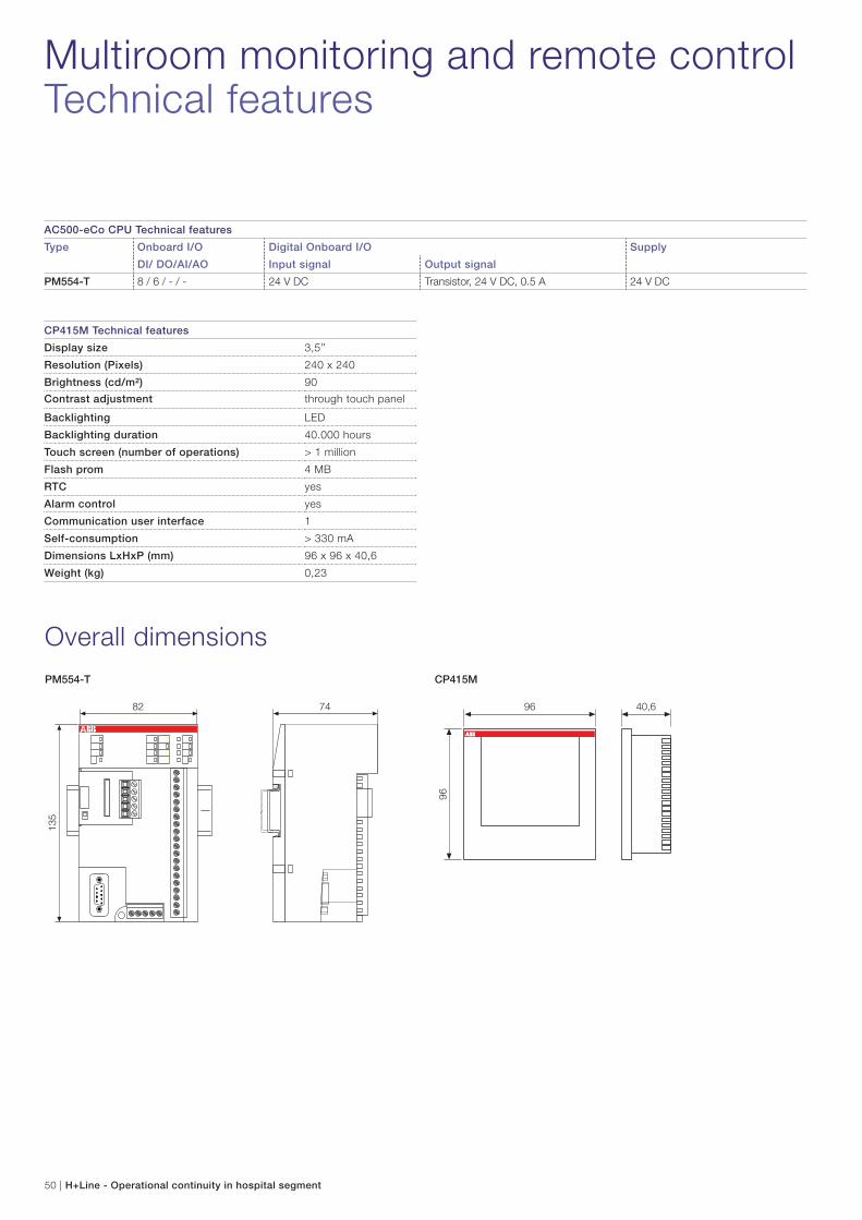
CP415M Technical features
Display size 3,5’’
Resolution (Pixels) 240 x 240
Brightness (cd/m²) 90
Contrast adjustment through touch panel
Backlighting LED
Backlighting duration 40.000 hours
Touch screen (number of operations) > 1 million
Flash prom 4 MB
RTC yes
Alarm control yes
Communication user interface 1
Self-consumption > 330 mA
Dimensions LxHxP (mm) 96 x 96 x 40,6
Weight (kg) 0,23
AC500-eCo CPU Technical features
Type Onboard I/O Digital Onboard I/O Supply
DI/ DO/AI/AO Input signal Output signal
PM554-T 8 / 6 / - / - 24 V DC Transistor, 24 V DC, 0.5 A 24 V DC
Overall dimensions
PM554-T CP415M
135
82 74
96
96 40,6
H+Line - Operational continuity in hospital segment | 51
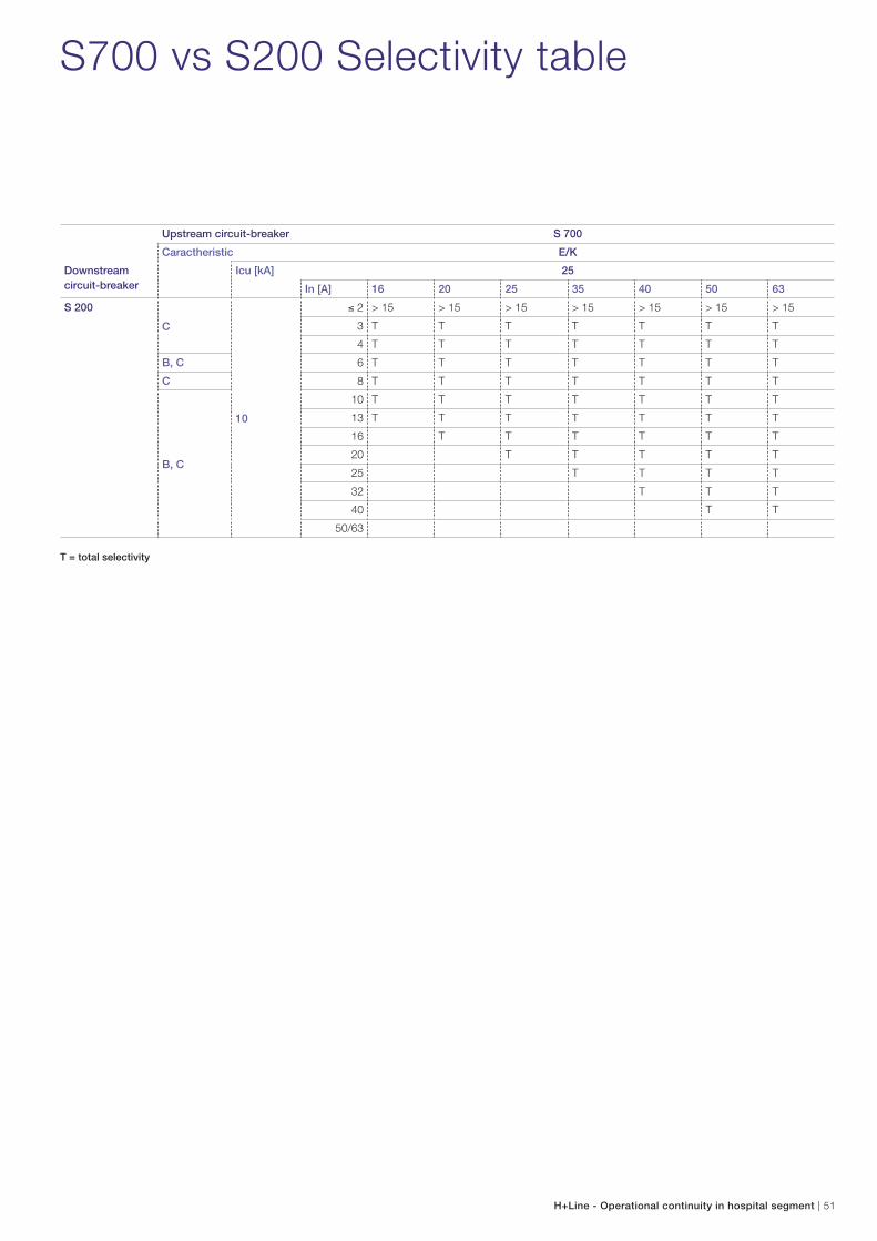
T = total selectivity
Upstream circuit-breaker S 700
Caractheristic E/K
Downstream circuit-breaker
Icu [kA] 25
In [A] 16 20 25 35 40 50 63
S 200
C
10
2 > 15 > 15 > 15 > 15 > 15 > 15 > 15
3 T T T T T T T
4 T T T T T T T
B, C 6 T T T T T T T
C 8 T T T T T T T
B, C
10 T T T T T T T
13 T T T T T T T
16 T T T T T T
20 T T T T T
25 T T T T
32 T T T
40 T T
50/63
S700 vs S200 Selectivity table
52 | H+Line - Operational continuity in hospital segment
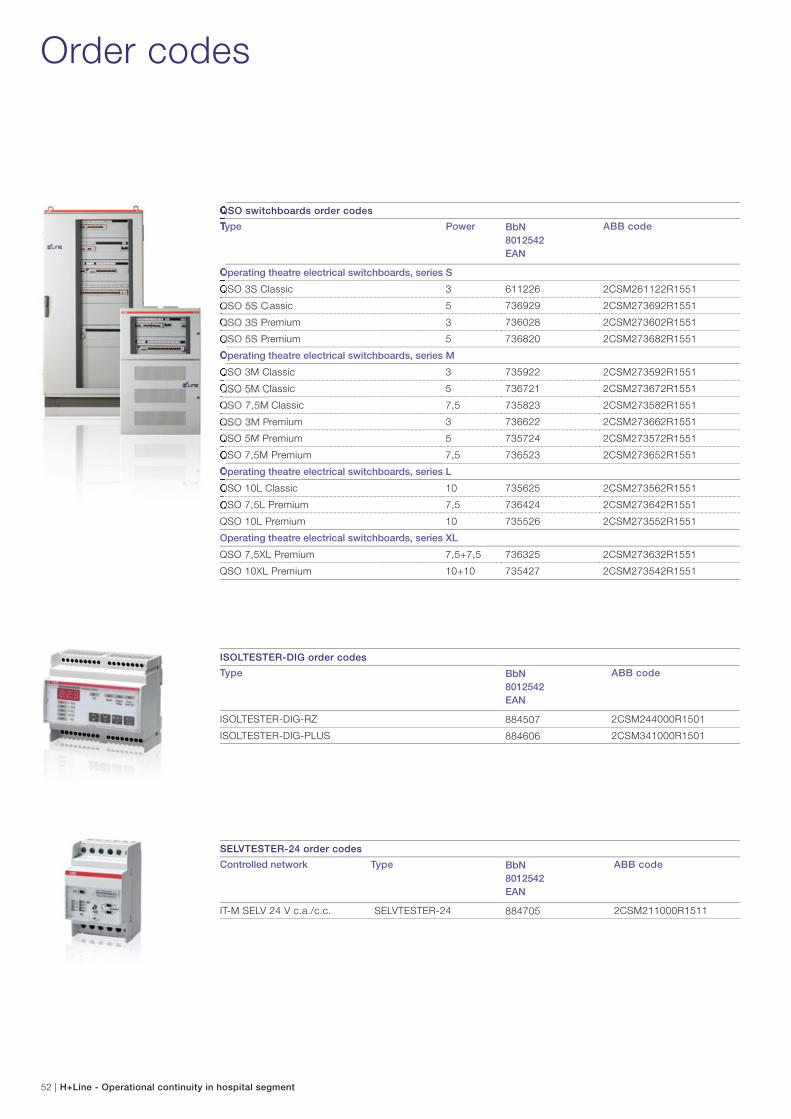
SELVTESTER-24 order codes
Controlled network Type BbN 8012542 EAN
ABB code
IT-M SELV 24 V c.a./c.c. SELVTESTER-24 884705 2CSM211000R1511
ISOLTESTER-DIG order codes
Type BbN 8012542 EAN
ABB code
ISOLTESTER-DIG-RZ 884507 2CSM244000R1501
ISOLTESTER-DIG-PLUS 884606 2CSM341000R1501
Order codes
QSO switchboards order codes
Type Power BbN 8012542 EAN
ABB code
Operating theatre electrical switchboards, series S
QSO 3S Classic 3 611226 2CSM261122R1551
QSO 5S Classic 5 736929 2CSM273692R1551
QSO 3S Premium 3 736028 2CSM273602R1551
QSO 5S Premium 5 736820 2CSM273682R1551
Operating theatre electrical switchboards, series M
QSO 3M Classic 3 735922 2CSM273592R1551
QSO 5M Classic 5 736721 2CSM273672R1551
QSO 7,5M Classic 7,5 735823 2CSM273582R1551
QSO 3M Premium 3 736622 2CSM273662R1551
QSO 5M Premium 5 735724 2CSM273572R1551
QSO 7,5M Premium 7,5 736523 2CSM273652R1551
Operating theatre electrical switchboards, series L
QSO 10L Classic 10 735625 2CSM273562R1551
QSO 7,5L Premium 7,5 736424 2CSM273642R1551
QSO 10L Premium 10 735526 2CSM273552R1551
Operating theatre electrical switchboards, series XL
QSO 7,5XL Premium 7,5+7,5 736325 2CSM273632R1551
QSO 10XL Premium 10+10 735427 2CSM273542R1551
H+Line - Operational continuity in hospital segment | 53
QSD-DIG 230/24 order codes
Installation Type BbN 8012542 EAN
ABB code
Horizontal QSD-DIG 230/24 730637 2CSM273063R1521
Vertical QSD-DIG 230/24 V 570936 2CSM257093R1521
Medical insulating transformers order codes
Description Type PT100 Probes BbN 8012542 EAN
ABB code
Insulating transformer 3 kVA TI 3 2896005 2CSM110000R1541
Insulating transformer 5 kVA TI 5 2896104 2CSM120000R1541
Insulating transformer 7,5 kVA TI 7.5 2896203 2CSM130000R1541
Insulating transformer 10 kVA TI 10 2521204 2CSM140000R1541
Insulating transformer 3 kVA TI 3-S 2521402 2CSM210000R1541
Insulating transformer 5 kVA TI 5-S 2521501 2CSM220000R1541
Insulating transformer 7,5 kVA TI 7.5-S 2521600 2CSM230000R1541
Insulating transformer 10 kVA TI 10-S 2521709 2CSM240000R1541
Anti-jamming dampers for transformers AMM 2CSM900000R1541
Multiroom monitoring system order codes
Description Type BbN 8012542 EAN
ABB code
PLC 8 IN and 6 OUT -
HMI touch 3.5’’ - H+Line sw
ISOLTESTER MRM BOX 736127 2CSM273612R1521
Operator’s terminal touch 3.5 ‘’ -
H+Line sw
ISOLTESTER MRM CPU 735229 2CSM273522R1521
QIT switchboards order codes
Description Type Power BbN 8012542 EAN
ABB code
QIT 16L Premium IT switchboard
for data center
16 kVA 735328 2CSM273532R1551
54 | H+Line - Operational continuity in hospital segment
Questions and answers
What does HI_ can be displayed on ISOLTESTER-DIG-RZ
insulation monitoring device mean?
It means high insulation. ISOLTESTER-DIG-RZ displays, thanks
to its three digit display, the real time insulation measure up to
999 kΩ. HI appears whenever the detected insulation is higher
than this value.
What does LF_ which can be displayed on ISOLTESTER-
DIG-RZ insulation monitoring device mean?
It means “Link Fail”. ISOLTESTER-DIG-RZ display is capable
of carrying out an internal self diagnosis to verify whether the
measurement of the insulation is correctly performed. If the
indication LF appears, it may mean that:
1. The device has not been wired correctly. In this case it is
necessary to verify the wiring according to the installation
electrical scheme.
2. There are electrical devices that discharge some direct
current interference on the PE safety conductor which
affects ISOLTESTER-DIG-RZ measuring signal.
In this case it is necessary to verify the dispersion by means
of a tester. ABB has developed ISOLTESTER-DIG-PLUS
specifically in order to operate also in a strongly interfered
context.
Which insulation value shall I set on ISOLTESTER-DIG as
insulation threshold?
There are not normative prescription. It all depends on the level
of protection you want for the system. The higher the threshold,
the higher the protection. On the other hand, the higher the
threshold, the higher the possibility to be warned. A useful
recomendation may be setting the threshold around 20% below
the insulation measured in standard operating conditions.
How do I enter ISOLTESTER-DIG setup menu?
Press “MINUS” and “SET/RESET” pushbutton simultaneously.
How do I access the ISOLTESTER-DIG regulator menu?
Press “SET/RESET” pushbutton.
How many signalling panels can I connect to each
insulation monitor?
You can connect up to 4 remote parallel signalling panels,
without adding any auxiliary supply.
Is it possible to use the same QSO switchboards to feed
two (or more) group 2 medical facilities?
The IEC 60364-7-710 reference standard does not allow this
application.
Any medical facility must be supplied by a dedicated medical
insulating transformer. “For any group of functionally connected
facilities at least an IT-M system is necessary” (article 710.512)
Shall I avoid the protection related with the insulation
monitoring device by means of a fuse, in order to avoid the
risk of the monitor being disconnected?
The protection of the insulation monitoring device is necessary
to protect the device from short circuits, in particular at the
end of the equipment useful life. Without a suitable protection,
a fire could be produced which should damage seriously the
switchboard. For these reasons, in accordance with the IEC
60364 reference standard, the switchboard manufacturer
cannot ignore the duty of protection.
It is also true that the insulation monitoring device cannot be
accidentally disconnected for several reasons:
1. QSO Switchboards are equipped with a locked door. Only
qualified and authorized personnel are expected to open it.
2. The E 91hN/32 fuse holder that protects the insulation
monitoring device has no disconnecting performance
under load, and therefore, in order to open the handle it is
necessary to operate on the circuit upstream, disconnecting
this way the operating theatre from the supply.
3. The E 91hN/32 fuse holder is sealed, and it may only be
opened intentionally.
How many CP415M Touch Screen displays can I connect
to each multiroom supervision system?
Up to two displays may be installed for each system, and
consequently for each PLC. In this way, visualization and
management of the alarms may be carried out from different
points of the building.
How is it possible to connect 99 ISOLTESTER-DIG-PLUS to
a single PLC with only few input channels?
The connection between ISOLTESTER-DIG-PLUS and the
PLC is via bus. This mean that no point to point connection is
needed and only one PLC input is used.
Does ABB release the QSO declaration of conformity?
Certainly.
H+Line - Operational continuity in hospital segment | 55
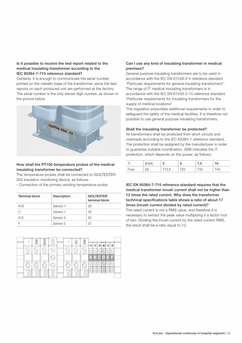
Is it possible to receive the test report related to the
medical insulating transformer according to the
IEC 60364-7-710 reference standard?
Certainly. It is enough to communicate the serial number
printed on the metallic base of the transformer, since the test
reports on each produced unit are performed at the factory.
The serial number is the only eleven digit number, as shown in
the picture below.
How shall the PT100 temperature probes of the medical
insulating transformer be connected?
The temperature probes shall be connected to ISOLTESTER-
DIG insulation monitoring device, as follows:
- Connection of the primary winding temperature probe:
Can I use any kind of insulating transformer in medical
premises?
General purpose insulating transformers are to be used in
accordance with the IEC EN 61558-2-4 reference standard
“Particular requirements for general insulating transformers”.
The range of IT medical insulating transformers is in
accordance with the IEC EN 61558-2-15 reference standard
“Particular requirements for insulating transformers for the
supply of medical locations”.
This regulation prescribes additional requirements in order to
safeguard the safety of the medical facilities. It is therefore not
possible to use general purpose insulating transformers.
Shall the insulating transformer be protected?
All transformers shall be protected from short circuits and
overloads according to the IEC 60364-1 reference standard.
The protection shall be assigned by the manufacturer in order
to guarantee suitable coordination. ABB indicates the IT
protection, which depends on the power, as follows:
IEC EN 60364-7-710 reference standard requires that the
medical transformer inrush current shall not be higher than
12 times the rated current. Why does the transformer
technical specifications table shows a ratio of about 17
times (inrush current divided by rated current)?
The rated current is not a RMS value, and therefore it is
necessary to extract the peak value multiplying it a factor root
of two. Dividing the inrush current by the rated current RMS,
the result shall be a ratio equal to 12.
Terminal block Description ISOLTESTER terminal block
A-B Sensor 1 28
C Sensor 1 30
D-E Sensor 2 25
F Sensor 2 27
PC
230
230
SC
H
R
A
R
B
W
C
R
E
W
F
R
D
R
TI [KVA] 3 5 7,5 10
Fuse [A] T12,5 T20 T32 T40

Contact us
2C
SC
00
40
33
B0
20
2 -
07
/20
11
ABB SACEA division of ABB S.p.A.Modular DevicesViale dell’Industria, 1820010 Vittuone (MI) - ItalyTel.: +39 02 9034 1 Fax: +39 02 9034 7609 www.abb.com
The data and illustrations are not binding. We reserve the right to modify the contents of this document on the basis of technical development of the products, without prior notice.
Copyright 2009 ABB. All rights reserved.