Embed Size (px)
Citation preview
OPERATIONS MANUAL
Side-Winder™
Operating Instructions
Coil CradleTension Clip
Locking Knob
Rail Clip
PRO-II PRO-III PRO 14™ position
PRO 2000® PRO 19™ position
Rail Clip
Tension Clip
Brake’s Back Rail
Brake’s Front Base Hinge
STEP 1Set up is fast and easy. First, install Tension Clip with Locking Knob onto middle support rail in correct hole position for your brake. Do not tighten. See illustration above.
STEP 2Attach Side-Winder to the brake by inserting Back Rail Clip into the brake’s Back (Box) Rail and Tension Clip onto your brake’s Front Base Hinge. Tighten Locking Knob.
STEP 3Remove Cradle Roller from Coil Cradle by grasping and unhooking Roller Clips at each end. To load coil finish side UP see steps 4a & 4b. To load coil finish side DOWN see steps 5a, 5b & 5c.
COIL CRADLE
Cradle Roller
Roller Clip
Coil Cradle
Roller Tube
NOTE: Direction of Coil Material
STEP 4aTo load coil finish side UP, insert Coil Cradle into centre of coil then attach Cradle Roller to Coil Cradle over TOP of coil.
Finish Side UP
L O A D I N G T H E C O I L C R A D L E :
2
WWW.TAPCO-EUROPE-TOOLS.COM
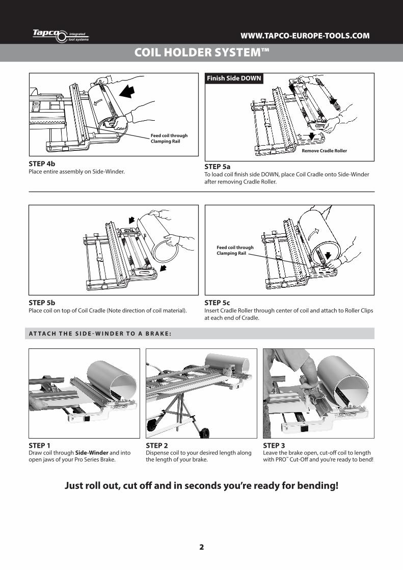
COIL HOLDER SYSTEM™
Feed coil through Clamping Rail
STEP 4bPlace entire assembly on Side-Winder.
STEP 5aTo load coil finish side DOWN, place Coil Cradle onto Side-Winder after removing Cradle Roller.
Remove Cradle Roller
Finish Side DOWN
STEP 5bPlace coil on top of Coil Cradle (Note direction of coil material).
Feed coil through Clamping Rail
STEP 5cInsert Cradle Roller through center of coil and attach to Roller Clips at each end of Cradle.
STEP 3Leave the brake open, cut-off coil to length with PRO™ Cut-Off and you’re ready to bend!
STEP 1Draw coil through Side-Winder and into open jaws of your Pro Series Brake.
STEP 2Dispense coil to your desired length along the length of your brake.
Just roll out, cut off and in seconds you’re ready for bending!
AT T A C H T H E S I D E - W I N D E R T O A B R A K E :
3
WWW.TAPCO-EUROPE-TOOLS.COM
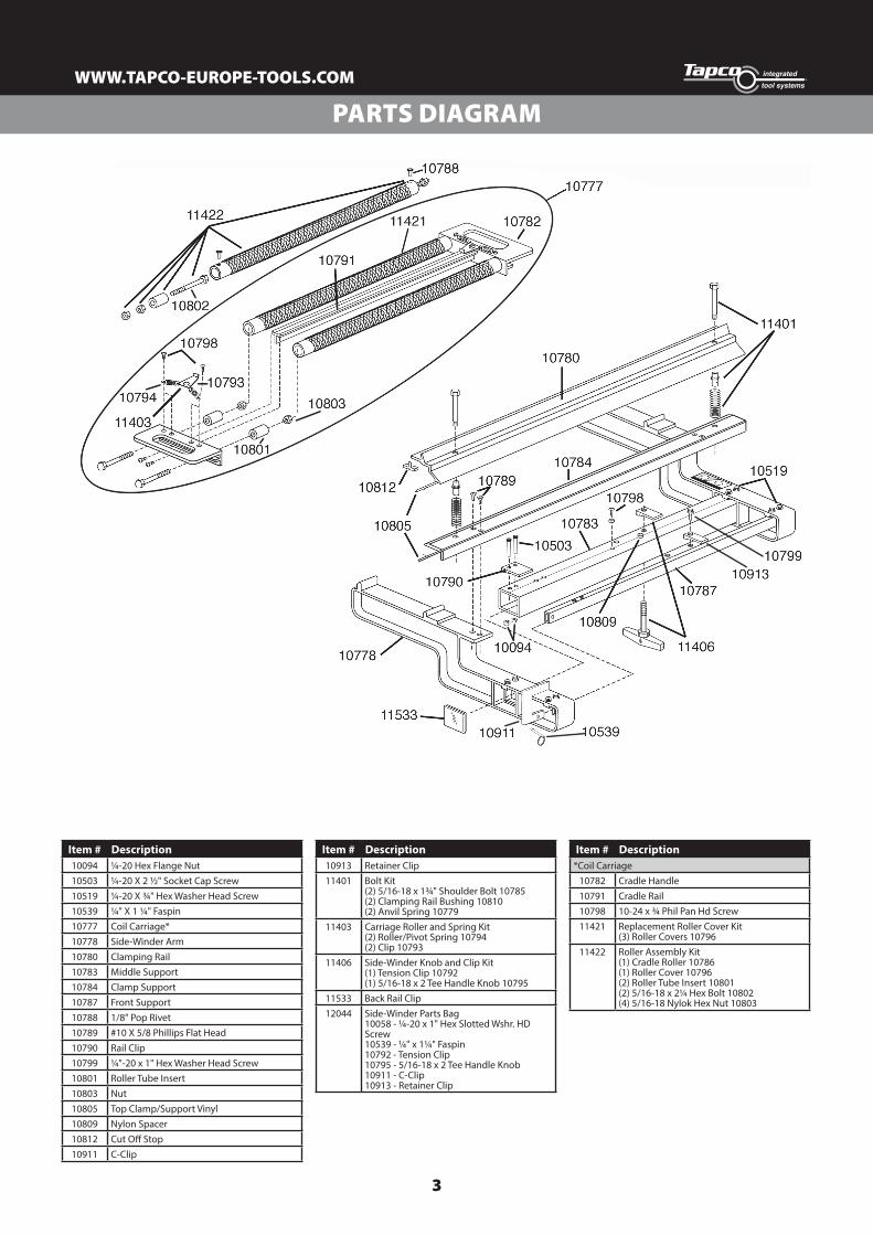
PARTS DIAGRAM
Item # Description10094 ¼-20 Hex Flange Nut10503 ¼-20 X 2 ½" Socket Cap Screw10519 ¼-20 X ¾" Hex Washer Head Screw10539 ¼" X 1 ¼" Faspin10777 Coil Carriage*10778 Side-Winder Arm10780 Clamping Rail10783 Middle Support10784 Clamp Support10787 Front Support10788 1/8" Pop Rivet10789 #10 X 5/8 Phillips Flat Head10790 Rail Clip10799 ¼"-20 x 1" Hex Washer Head Screw10801 Roller Tube Insert10803 Nut10805 Top Clamp/Support Vinyl10809 Nylon Spacer10812 Cut Off Stop10911 C-Clip
Item # Description10913 Retainer Clip11401 Bolt Kit
(2) 5/16-18 x 1¾" Shoulder Bolt 10785 (2) Clamping Rail Bushing 10810 (2) Anvil Spring 10779
11403 Carriage Roller and Spring Kit (2) Roller/Pivot Spring 10794 (2) Clip 10793
11406 Side-Winder Knob and Clip Kit (1) Tension Clip 10792 (1) 5/16-18 x 2 Tee Handle Knob 10795
11533 Back Rail Clip12044 Side-Winder Parts Bag
10058 - ¼-20 x 1" Hex Slotted Wshr. HD Screw10539 - ¼" x 1¼" Faspin10792 - Tension Clip10795 - 5/16-18 x 2 Tee Handle Knob10911 - C-Clip10913 - Retainer Clip
Item # Description*Coil Carriage
10782 Cradle Handle10791 Cradle Rail10798 10-24 x ¾ Phil Pan Hd Screw11421 Replacement Roller Cover Kit
(3) Roller Covers 1079611422 Roller Assembly Kit
(1) Cradle Roller 10786 (1) Roller Cover 10796 (2) Roller Tube Insert 10801 (2) 5/16-18 x 2¼ Hex Bolt 10802 (4) 5/16-18 Nylok Hex Nut 10803
4
WWW.TAPCO-EUROPE-TOOLS.COM
Item #12053©2014 Tapco International Corporation
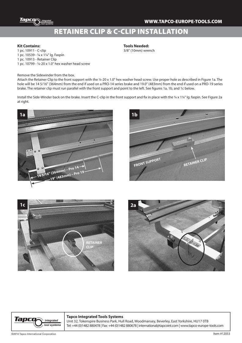
RETAINER CLIP & C-CLIP INSTALLATION
Tapco Integrated Tools SystemsUnit 32, Tokenspire Business Park, Hull Road, Woodmansey, Beverley, East Yorkshire, HU17 0TBTel: +44 (0)1482 880478 | Fax: +44 (0)1482 880678 | [email protected] | www.tapco-europe-tools.com
Kit Contains:1 pc. 10911 - C-clip1 pc. 10539 - ¼ x 1¼" lg. Faspin1 pc. 10913 - Retainer Clip1 pc. 10799 - ¼-20 x 1.0" hex washer head screw
Tools Needed:3/8" (10mm) wrench
Remove the Sidewinder from the box.Attach the Retainer Clip to the front support with the ¼-20 x 1.0" hex washer head screw. Use proper hole as described in Figure 1a. The hole will be 14 5/16" (364mm) from the end if used on a PRO-14 series brake and 19.0" (483mm) from the end if used on a PRO-19 series brake. The retainer clip must run parallel with the front support and point to the left. See figures 1a, 1b, and 1c below.
Install the Side-Winder back on the brake. Insert the C-clip in the front support and fix in place with the ¼ x 1¼" lg. faspin. See Figure 2a at right.
1a
1c
1b
2a
14 5/16" (364mm) – Pro 14
19" (483mm) – Pro 19
FRONT SUPPORT
RETAINER CLIP
RETAINERCLIP