Embed Size (px)
Citation preview
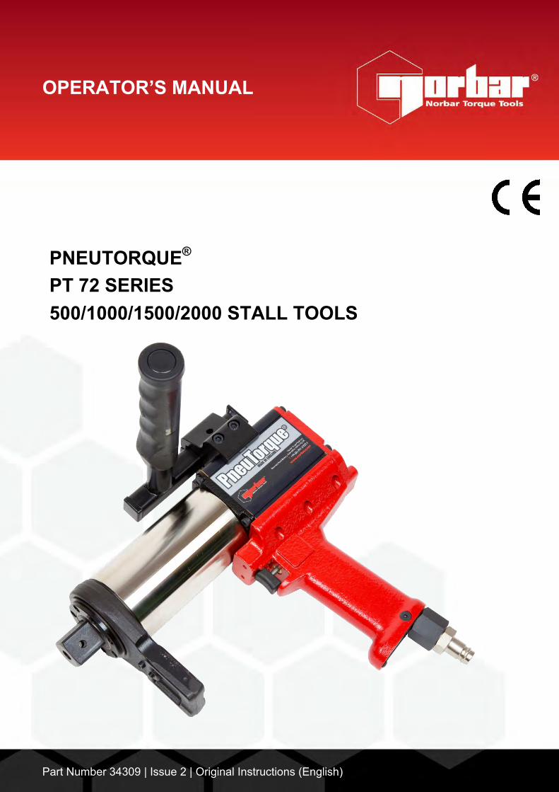
OPERATOR’S MANUAL
PNEUTORQUE®
PT 72 SERIES 500/1000/1500/2000 STALL TOOLS
Part Number 34309 | Issue 2 | Original Instructions (English)
NORBAR TORQUE TOOLS LTD Beaumont Road, Banbury, Oxfordshire, OX16 1XJ UNITED KINGDOM Tel + 44 (0)1295 270333 Email [email protected]
NORBAR TORQUE TOOLS PTY LTD 45–47 Raglan Avenue, Edwardstown, SA 5039 AUSTRALIA Tel + 61 (0)8 8292 9777 Email [email protected]
NORBAR TORQUE TOOLS INC 36400 Biltmore Place, Willoughby, Ohio, 44094 USA Tel + 1 866 667 2279 Email [email protected]
NORBAR TORQUE TOOLS (NZ) LTD B3/269A Mt Smart Road Onehunga, Auckland 1061 NEW ZEALAND Tel + 64 9579 8653 Email [email protected]
NORBAR TORQUE TOOLS PTE LTD 194 Pandan Loop #07-20 Pantech Business Hub SINGAPORE 128383 Tel + 65 6841 1371 Email [email protected]
NORBAR TORQUE TOOLS (SHANGHAI) LTD E Building–5F, no. 1618 Yishan Road, Minhang District, Shanghai CHINA 201103 Tel + 86 21 6145 0368 Email [email protected]
NORBAR TORQUE TOOLS INDIA PVT. LTD Plot No A-168, Khairne Industrial Area, Thane Belapur Road, Mahape, Navi Mumbai – 400 709 INDIA Tel + 91 22 2778 8480 Email [email protected] www.norbar.com
© Norbar Torque Tools Ltd 2005


1
CONTENTS Part Numbers Covered by This Manual 1 Safety 2 Introduction 3 Parts Included 3 Accessories 3 Features and Functions 4 Set up Instructions 5 Torque Reaction 6 Setting Clockwise/Counter-Clockwise Operation 7 Setting Torque for Bolt Tightening 7 Setting Torque for Releasing Bolt 7 Operating Instructions 8 Tightening 8 Releasing 8 Maintenance 9 Air Lubrication 9 Gearbox 9 Silencer 9 Drive Square 10 Cleaning 10 Disposal 10 Specifications 11 Declaration of Conformity 12 Trouble shooting 13 Glossary of terms 13
PART NUMBERS COVERED BY THIS MANUAL
This manual covers all “PT 72mm series” tools supplied with pistol grip handles; including the following:
Part Number Model Square Maximum Torque 18023 PT 72/500
3/4” 500 N∙m 18023.AUT PT 72/500 Auto 2 speed
18022 PT 72/1000 3/4” 1000 N∙m
18022.AUT PT 72/1000 Auto 2 speed 18026 PT 72/1000
1” 1000 N∙m 18026.AUT PT 72/1000 Auto 2 speed
18021 PT 72/1500 1” 1500 N∙m
18021.AUT PT 72/1500 Auto 2 speed 18033 PT 72/2000
1” 2000 N∙m 18033.AUT PT 72/2000 Auto 2 speed
PT 72mm series tools are also supplied in a ‘remote’ form without a handle. These are covered by operator’s manual part number 34310.

2
SAFETY IMPORTANT: DO NOT OPERATE THE TOOL BEFORE READING THESE INSTRUCTIONS. FAILURE
TO DO SO MAY RESULT IN PERSONAL INJURY OR DAMAGE TO THE TOOL. This tool is intended for use with threaded fasteners. Any other use is not recommended. The use of ear protectors is recommended. Do not use tool in potentially explosive atmosphere as these tools contain grease, which may cause an explosion hazard in the presence of pure oxygen. These tools also contain aluminium alloy components which may cause a hazard in certain explosive environments. Be aware of unexpected tool movement due to reaction forces as this may cause injuries. Failure of the drive square may also cause unexpected tool movement. Isolate the tool from all energy sources before changing or adjusting the drive square or socket.
There is a risk of crushing between the reaction bar and work piece. Keep hands away from reaction bar. Keep hands away from tool output.
Keep loose clothing, hair, etc. from being caught in any rotating part of the tool. These tools require a reaction bar. See section on Torque Reaction. Ensure all hoses are correctly fitted before switching on the air supply. This avoids the risk of injury by whipping air hoses. Unexpected direction of inserted tool movement can cause a hazardous situation. Use only sockets and adaptors which are in good condition and are intended for use with power tools. Pneutorque® Wrenches are reversible, non-impacting, torque controlled bolt tightening tools and must always be operated with the following:
Clean dry air supply with a minimum flow of 11 litres/sec (23 CFM).
Lubro Control Unit or similar Filter, Regulator and Lubricator Unit 1/2” Bore (12 mm).
Impact or high quality sockets.
Reaction Plate.

3
INTRODUCTION The Pneutorque® 72mm series are air driven power tools designed for applying torque to threaded fasteners. An external pressure regulator (Lubro Control Unit) is needed; this allows the air pressure to be adjusted to determine the stall torque from the graph provided. There are models to cover torque capacities of 500 N∙m to 2000 N∙m. Parts Included
Part Number Description Quantity 180***.*** Pneutorque® 1
18290 Reaction Adaptor 1 18298 Reaction Plate 1
18343.148 Lifting Handle (Only PT 72/****) 1 18343.220 Lifting Handle (Only PT 72/****.AUT) 1
26588 Reaction Plate Retaining Circlip 1 34309 Operators Manual 1 34209 Air Pressure Graph 1
Accessories
Part Number Description 18349.006 6” Nose Extension 18349.009 9” Nose Extension 18349.012 12” Nose Extension 18349.015 15” Nose Extension 18349.018 18” Nose Extension
18221 ¾” Drive Square 18220 1” Drive Square 18292 Single-sided Reaction Plate 18293 Double-sided Reaction Plate 18286 Lifting Arm 18266 Silencer 16074 Lubro Control Unit ***** Annular Transducer
4
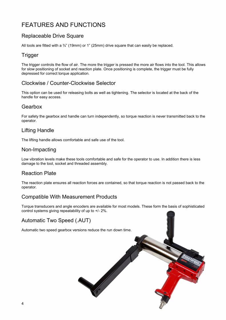
FEATURES AND FUNCTIONS Replaceable Drive Square All tools are fitted with a ¾” (19mm) or 1” (25mm) drive square that can easily be replaced. Trigger The trigger controls the flow of air. The more the trigger is pressed the more air flows into the tool. This allows for slow positioning of socket and reaction plate. Once positioning is complete, the trigger must be fully depressed for correct torque application. Clockwise / Counter-Clockwise Selector This option can be used for releasing bolts as well as tightening. The selector is located at the back of the handle for easy access. Gearbox For safety the gearbox and handle can turn independently, so torque reaction is never transmitted back to the operator. Lifting Handle The lifting handle allows comfortable and safe use of the tool. Non-Impacting Low vibration levels make these tools comfortable and safe for the operator to use. In addition there is less damage to the tool, socket and threaded assembly. Reaction Plate The reaction plate ensures all reaction forces are contained, so that torque reaction is not passed back to the operator. Compatible With Measurement Products Torque transducers and angle encoders are available for most models. These form the basis of sophisticated control systems giving repeatability of up to +/- 2%. Automatic Two Speed (.AUT) Automatic two speed gearbox versions reduce the run down time.

5
SET UP INSTRUCTIONS
WARNING: TO AVOID HAZARD FROM WHIPPING AIR HOSES MAKE ALL CONNECTIONS TO THE TOOL BEFORE TURNING ON THE AIR SUPPLY.
Make sure all air hoses are clean and free from dirt. Connect the tool air inlet hose (A.) to the outlet side of the pressure regulator unit, observing air flow direction arrows. Use a ½” bore hose with a maximum length of 3m. TIP: To connect the air inlet hose to a 1/2” bore hose use a ½” BSP Male/Male connector. A pair of
spanners will be required to perform this task (22mm (7/8”) A/F and 24mm (15/16”) A/F open-ended spanners).
Connect the inlet side of the pressure regulator unit to the air supply using a minimum hose size of ½” bore (12mm). Avoid using ½” bore hoses of longer than 5 meters from the supply to the pressure regulator unit as this will reduce the performance of the tool.
Check the oil level in the lubricator and fill to the correct level. (See MAINTENANCE section).
Attach the Reaction Plate (B.) to Reaction Adaptor (C.) adjacent to the Output Drive (D.) of wrench ensuring the Locking Plunger (E.) is correctly engaged in the Reaction Plate. Fit circlip to secure Reaction Adaptor. If required fit lifting handle (Figure 2) to top of the Air Motor Housing (F.). Adjust the handle position so the wrench can be held comfortably. Tighten the socket screws securely.
Clockwise/Counter- Clockwise Switch
(G.)
Handle (I.)
Trigger (H.)
Air Motor Housing (F.)
Reaction Plate (B.)
Locking Plunger (E.)
Reaction Adaptor (C.)
Output Square Drive (D.)
Air Inlet (A.)
FIGURE 2
FIGURE 1

6
Torque Reaction It is essential the reaction plate rests squarely against a solid object or surface adjacent to the fastener to be tightened. The contact area must be within the shaded area of Figure 3, with the contact area as large as possible.
WARNING: CARE MUST BE TAKEN TO ENSURE THAT THE REACTION PLATE IS ONLY USED WITHIN THE LIMITATIONS SHOWN IN FIGURE 3.
For special applications or where extra deep sockets must be used the standard plate may be extended but only within the limitations shown on Figure 3. Alternative reaction devices are available.
WARNING: FAILURE TO OBSERVE THE LIMITATIONS SHOWN IN FIGURE 3 WHEN MODIFYING STANDARD REACTION PLATES MAY RESULT IN PREMATURE WEAR OR DAMAGE TO THE TOOL.
Standard drive square extensions MUST NOT be used as these will cause serious damage to the tool output drive. A range of nose extensions is available for applications where access is restricted. These are designed to support the final drive correctly. When the Pneutorque® is in operation the reaction plate rotates in the opposite direction to the output drive square and must be allowed to rest squarely against a solid object or surface adjacent to the bolt to be tightened. (See Figure 4).
WARNING: ALWAYS KEEP HANDS CLEAR OF THE REACTION PLATE WHEN THE TOOL IS IN USE OR SERIOUS INJURY MAY RESULT.
Clockwise Operation Anti-Clockwise Operation
Reaction point
FIGURE 4
FIGURE 3
Torque Reaction should be taken in the shaded areas only
Extra Length Socket
Standard Length Socket

7
Setting Clockwise/Counter-Clockwise Operation
WARNING: FAILURE TO FULLY ENGAGE THE CLOCKWISE/COUNTER- CLOCKWISE OPERATION SELECTOR WILL RESULT IN DAMAGE TO THE SELECTOR VALVE.
Setting Torque for Bolt Tightening These tools use the air pressure set on an external pressure regulator unit to determine the stall torque. They are supplied with an Air Pressure Graph which relates torque output to air pressure. Set the torque output as follows:
1. Ensure the Clockwise/Counter-clockwise Selector (Figure 5 & Figure 6) is correctly set.
2. Establish the air pressure required using the Air Pressure Graph.
3. With the tool running, adjust the pressure regulator until the correct figure is shown on the gauge.
IMPORTANT: THE WRENCH MUST BE FREE RUNNING WHILE ADJUSTING THE AIR PRESSURE TO GIVE THE CORRECT SETTING.
WHILE THE WRENCH IS FREE RUNNING CHECK THAT LUBRO CONTROL UNIT IS
SUPPLYING APPROXIMATELY SIX DROPS OF OIL PER MINUTE. Setting Torque for Releasing Bolt 1. Ensure the Clockwise/Counter-clockwise Selector (Figure 5 & Figure 6) is correctly set. 2. Pull trigger to loosen fastener. TIP: Increase air pressure slightly if fastener will not release.
WARNING: EXCEEDING THE MAXIMUM AIR PRESSURE WILL CAUSE OVERLOADING AND MAY LEAD TO SERIOUS DAMAGE.
WARNING: CHANGING THE AIR PRESSURE AFTER SETTING THE PRESSURE
REGULATOR WILL CHANGE THE STALL TORQUE VALUE.
FIGURE 5 – Clockwise FIGURE 6 – Counter-clockwise

8
OPERATING INSTRUCTIONS
WARNING: KEEP HANDS CLEAR OF THE REACTION PLATE. WARNING: WHEN USING THIS TOOL IT MUST BE SUPPORTED AT ALL TIMES IN
ORDER TO PREVENT UNEXPECTED RELEASE IN THE EVENT OF FASTENER OR COMPONENT FAILURE.
WARNING: CHANGING THE AIR PRESSURE AFTER SETTING THE PRESSURE
REGULATOR WILL CHANGE THE STALL TORQUE VALUE. Tightening 1. Fit Pneutorque® with the correct size impact or high quality socket. 2. Ensure the Clockwise/Counter-clockwise Selector is correctly set. 3. Rotate tool and reaction plate into a convenient position. Fit the tool onto the fastener. Locate reaction plate adjacent to the reaction point.
4. Adopt a suitable posture to counteract normal or unexpected
movement of the tool due to reaction forces.
5. Gently press Trigger to bring the reaction plate into contact with the reaction point.
6. Fully press trigger and keep fully depressed until tool stalls then release trigger.
If the trigger is not fully pressed full torque will not be applied to the fastener. 7. Remove tool from fastener. Releasing 1. Fit Pneutorque® with the correct size impact or high quality socket. 2. Ensure the clockwise/counter-clockwise selector is correctly set.
3. Rotate tool and reaction plate into a convenient position.
Fit the tool onto the fastener. Locate reaction plate adjacent to the reaction point.
4. Adopt a suitable posture to counteract normal or unexpected movement of the tool due to reaction forces.
5. Gently press Trigger to bring the reaction plate into contact with the reaction point.
6. Fully press trigger and keep fully depressed until bolt releases. TIP: If unable to release the bolt increase the air pressure to the tool. Do not use excessive air
pressure.
WARNING: EXCEEDING THE MAXIMUM AIR PRESSURE WILL CAUSE OVERLOADING AND MAY LEAD TO SERIOUS DAMAGE.
7. Remove tool from fastener.

9
FIGURE 7
MAINTENANCE To maintain optimum performance and safety, regular maintenance needs to be carried out. The only user maintenance required on these tools is the replacement of drive squares and the silencer. Any other maintenance or repairs should be carried out by Norbar or a Norbar approved agent and should form part of a service. Service intervals will depend on the type of usage of the tools and the environment in which they are being used. The maximum recommended maintenance and recalibration interval is 12 months. TIP: Steps the operator can take to reduce the amount of maintenance required include:
1. Use the tool in a clean environment. 2. Use an air compressor fitted with a dryer. 3. Ensure the Lubro Control Unit has sufficient hydraulic oil. 4. Ensure the Lubro Control Unit delivers hydraulic oil at the correct rate. 5. Ensure the Lubro Control Unit is regularly maintained, see product manual. 6. Maintain the correct torque reaction.
Air Lubrication Add Shell Tellus S2M 32 or equivalent good quality hydraulic oil to the Lubro unit. Gearbox Under normal operating conditions it is not necessary to re-grease the gearbox. The gearbox contains Shell Gadus S2 V220 or equivalent good quality grease. Silencer The silencer (#18266) must be changed every 12 months. This may be more frequent for high tool usage or dirty environments. TIP: Change silencer with tool upside down, as shown, to ensure internal parts (spring & valve)
are kept in place. 1. Remove M4 screw (A) (#25381.10) using a 2.5mm hexagon
key. 2. Remove screw (B) (#25367.30) using a 3mm hexagonal key. 3. Pull out air inlet tube (D) with base plate & silencer. 4. Remove silencer (E) from air inlet tube. 5. Fit new silencer (#18266) over air inlet tube. 6. Fit air inlet tube assembly (C, D & E) into handle against spring
resistance. 7. Fit screw (B) with a 3mm hexagonal key. 8. Fit screw (A) with a 2.5mm hexagonal key. TIP: When refitting air inlet tube assembly into handle care should be taken to ensure correct
alignment between air inlet tube & spring. It may be easier to fit the spring into air inlet tube first and secure with a small amount of grease.
C A
D
E
B

10
Drive Square To avoid internal damage (especially due to torque overload), the output drive square has been designed to shear first. This saves major internal damage and allows easy square removal. The drive square can be replaced with either a ¾” drive square (#18221) or a 1” drive square (#18220). A new retaining screw (#25352.45) is supplied with the square. To replace drive square: 1. Use 4mm hexagon key to remove screw. 2. Remove drive square. 3. Fit new drive square. 4. Fit new screw and tighten to 8 N∙m - 9 N∙m. TIP: If the square has sheared it may be necessary to use pliers to remove the broken parts. Cleaning Keep the tool in a clean condition to aid safety. Do not use abrasives or solvent based cleaners. Disposal Recycling considerations:
Component Material Handle Aluminium casting with epoxy finish. Annulus Alloy steel with nickel plate finish.
Reaction plate Alloy steel with epoxy powder finish.
FIGURE 8

11
SPECIFICATIONS
Model Torque Tool Speed
(Free running at maximum air pressure) Minimum Maximum
PT 72/500 90 N∙m (66 lbf∙ft) 500 N∙m (370 lbf∙ft) 35 rev/min PT 72/500 Auto 2 speed 203 N∙m (150 lbf∙ft) 500 N∙m (370 lbf∙ft) 170 rev/min
PT 72/1000 190 N∙m (140 lbf∙ft) 1000 N∙m (740 lbf∙ft) 15 rev/min PT 72/1000 Auto 2 speed 488 N∙m (360 lbf∙ft) 1000 N∙m (740 lbf∙ft) 75 rev/min
PT 72/1000 190 N∙m (140 lbf∙ft) 1000 N∙m (740 lbf∙ft) 15 rev/min PT 72/1000 Auto 2 speed 488 N∙m (360 lbf∙ft) 1000 N∙m (740 lbf∙ft) 75 rev/min
PT 72/1500 300 N∙m (220 lbf∙ft) 1500 N∙m (1110 lbf∙ft) 9 rev/min PT 72/1500 Auto 2 speed 760 N∙m (560 lbf∙ft) 1500 N∙m (1110 lbf∙ft) 45 rev/min
PT 72/2000 400 N∙m (300 lbf∙ft) 2000 N∙m (1450 lbf∙ft) 6 rev/min PT 72/2000 Auto 2 speed 1000 N∙m (750 lbf∙ft) 2000 N∙m (1450 lbf∙ft) 30 rev/min
Repeatability: ± 5%
Air Supply: Maximum pressure 6.0 bar (For maximum torque capacity). Air consumption 11 litres / sec.
Recommended Lubrication: Shell Tellus S2M 32 for the Lubro Control Unit.
Temperature Range: 0°C to +50°C (operating). -20°C to +60°C (storage).
Maximum Operating Humidity: 85% Relative Humidity @30°C.
Model Tool Weight Reaction Weight Dimensions PT 72/**** 6.4 kg (14.1 lb) 1.7 kg (3.8 lb) 301mm x 72mm wide x 259mm
PT 72/**** Auto 2 speed 8.7 kg (19.2 lb) 1.7 kg (3.8 lb) 373mm x 72mm wide x 259mm
Maximum Vibration at Handle: < 2.5m/s2 Tested in accordance with ISO 8662-7 Hand Held portable tools – Measurement of vibrations at the handle.
Sound Pressure Level: 81 dBA measured at 1m equivalent continuous A weighted sound. Tested to BS ISO 3744: 1994 Acoustics – Determination of sound power levels of noise sources using sound pressure – Engineering method in an essentially free field over a reflecting plane. Test conducted in free running condition with a supply pressure of 6.0 bar.
Environment: Indoor & dry outdoor use within a light industrial environment. Due to continuous improvement all specifications are subject to change without prior notice. NOTE: If equipment is used in a manner not specified by the manufacturer, the protection
provided by the equipment could be impaired.

12

TROUBLE SHOOTING The following is only a guide, for more complex faults please contact your local Norbar distributor or Norbar directly. Problem Likely Solutions
Tool output does not rotate when trigger pulled.
Check air supply is functioning & connected. Check air pressure setting (at least 1 bar). Check correct setting of direction knob. Output drive square sheared, needs replacing. Gear train or air motor is damaged.
Drive square sheared. See maintenance section to replace.
Tool does not stall. Tool has not achieved torque, increase air pressure. Fastener sheared or thread stripped. Gear train or air motor is damaged.
GLOSSARY OF TERMS
Word Or Term Meaning
Air pressure graph Graph supplied with Stall only tool to show air pressure setting against required torque.
AUT Auto Two speed. Bi-directional Tool capable of Clockwise & Counter-clockwise square rotation. CFM Cubic Feet per minute, measure of air flow. BSP British Standard Pipe, this is a thread size.
Lubro Control Unit Unit to provide filtering and lubrication along with pressure regulation. Not supplied with tool.
Pneutorque® Product name. Reaction Arm Device to counteract applied torque.
13

OPERATOR’S MANUAL
PNEUTORQUE®
PT 72 SERIES 500/1000/1500/2000 STALL TOOLS
Part Number 34309 | Issue 2 | Original Instructions (English)
NORBAR TORQUE TOOLS LTD Beaumont Road, Banbury, Oxfordshire, OX16 1XJ UNITED KINGDOM Tel + 44 (0)1295 270333 Email [email protected]
NORBAR TORQUE TOOLS PTY LTD 45–47 Raglan Avenue, Edwardstown, SA 5039 AUSTRALIA Tel + 61 (0)8 8292 9777 Email [email protected]
NORBAR TORQUE TOOLS INC 36400 Biltmore Place, Willoughby, Ohio, 44094 USA Tel + 1 866 667 2279 Email [email protected]
NORBAR TORQUE TOOLS (NZ) LTD B3/269A Mt Smart Road Onehunga, Auckland 1061 NEW ZEALAND Tel + 64 9579 8653 Email [email protected]
NORBAR TORQUE TOOLS PTE LTD 194 Pandan Loop #07-20 Pantech Business Hub SINGAPORE 128383 Tel + 65 6841 1371 Email [email protected]
NORBAR TORQUE TOOLS (SHANGHAI) LTD E Building–5F, no. 1618 Yishan Road, Minhang District, Shanghai CHINA 201103 Tel + 86 21 6145 0368 Email [email protected]
NORBAR TORQUE TOOLS INDIA PVT. LTD Plot No A-168, Khairne Industrial Area, Thane Belapur Road, Mahape, Navi Mumbai – 400 709 INDIA Tel + 91 22 2778 8480 Email [email protected] www.norbar.com
© Norbar Torque Tools Ltd 2005