Embed Size (px)
Citation preview
POWER SYSTEMS, INC.
®
50
0 100OIL
300200
100
V
NOT IN AUTOMATICSTART MODE
OVERCRANK
OVERSPEED
TESTRESET
HIGHCOOLTEMP.
LOWOIL
PRESS.
RPMSENSOR
LOSS
200150
100
A
50
PRE ALARMLOWOFF
PRESS
PRE ALARMHIGHCOOLTEMP
LOWCOOLTEMP
ALARMHORN
ON - OFF
HIGHBATT
VOLTAGE
LOWBATT
VOLTAGE
RUPTUREBASIN
FILLING
LOWFUEL
HIGHFUEL
150
100
200
25TEMP
0
40 40AMPS
0000 1TOTAL HOURS
PREHEAT30 SEC
MAX START
STOP
AUTO
OFF
MANUAL
FUSE15-AAGC 0
3 1
INCREASE
VOLTAGEADJUST
65
60
Hz
Operator’s Manual“C” Option Control Panel
This manual should remain with the unit.
Generac® Power Systems, Inc.
Important Safety Instructions“C” Option Control Panel
SAVE THESE INSTRUCTIONS – The manufacturer suggests that these rules for safe operation be copied and posted in potential hazard areas. Safety should be stressed to alloperators and potential operators of this equipment.! !
Study these SAFETY RULES carefully beforeinstalling, operating, or servicing this equipment.Become familiar with this manual and all literaturepertaining to the generator set and related equip-ment. This equipment can operate safely, efficiently,and reliably only if it is properly installed, operated,and maintained. Many accidents are caused by failingto follow simple and fundamental rules or precau-tions.
Generac cannot possibly anticipate every possible cir-cumstance that might involve a hazard. The warn-ings in this manual, and on tags and decalsaffixed to the equipment, are, therefore, not all-inclu-sive. If using a procedure, work method, or operatingtechnique Generac does not specifically recommend,you must satisfy yourself that it is safe for you and oth-ers. Also must make sure the procedure, work method,or operating technique that is used does not render theequipment unsafe.
GENERAL HAZARDS• For safety reasons, Generac recommends that this
equipment be installed and serviced by a GeneracAuthorized Service Dealer or other qualified electri-cian or installation technician who is familiar withapplicable codes, standards, and regulations. Theoperator also must comply with all such codes, stan-dards, and regulations.
• When working on this equipment, remain alert at alltimes. Never work on the equipment when physical-ly or mentally fatigued.
• Inspect the equipment regularly, and promptly repairor replace all worn, damaged or defective parts,using only factory-approved parts.
• Before performing any maintenance on the generatoror any related equipment, disconnect the generator’sbattery cables and remove panel fuse to prevent acci-dental startup. Disconnect the cable from the batterypost, indicated by a NEGATIVE, NEG, or (–) first.Reconnect that cable last.
ELECTRICAL HAZARDS• Generators produce dangerous electrical voltages
and can cause fatal electrical shock. Avoid contactwith bare wires, terminals, connections, etc., whilethe generator and related equipment are running.Ensure all appropriate covers, guards, and barri-ers are in place before operating the equipment. Ifworking around an operating unit, stand on aninsulated, dry surface to reduce potential shockhazards.
• Do not handle any kind of electrical device whilestanding in water, while barefoot, or while hands orfeet are wet. DANGEROUS ELECTRICAL SHOCKMAY RESULT.
• If people must stand on metal or concrete whileinstalling, operating, servicing, adjusting, or repair-ing this equipment, place insulative mats over a drywooden platform. Work on the equipment only whilestanding on such insulative mats.
• Wire gauge sizes of electrical wiring, cables, and cordsets must be adequate to handle the maximum elec-trical current (amperage) to which they will be sub-jected to.
• Before installing or servicing this equipment, makesure that all power voltage supplies are positivelyTURNED OFF at their source. Failure to do so willresult in hazardous and possibly fatal electricalshock.
• When installed with an automatic transfer switch, thegenerator may crank and start anytime, withoutwarning. To prevent injuries caused by sudden start-up, disable the generator’s automatic start circuitbefore working on, or around, the unit. Then, placea “Do Not Operate” tag on the generator controlpanel and on the transfer switch.
• In case of an accident caused by electric shock,immediately shut down the source of electricalpower. If this is not possible, attempt to free the vic-tim from the live conductor. AVOID DIRECT CON-TACT WITH THE VICTIM. Use a nonconductingimplement, such as, a rope or board, to free the vic-tim from the live conductor. If the victim is uncon-scious, apply first aid and get immediate medicalhelp.
• Never wear jewelry when working on this equipment.Jewelry can conduct electricity, resulting in electricshock, or may get caught in moving components,causing injury.
FIRE HAZARDS• For fire safety, the generator and related equipment
must be installed and maintained properly.Installation always must comply with applicablecodes, standards, laws, and regulations. Adherestrictly to local, state, and national electrical andbuilding codes. Comply with regulations theOccupational Safety and Health Administration(OSHA) has established. Also, ensure that theequipment is installed in accordance with the man-ufacturer’s instructions and recommendations.Following proper installation, do nothing thatmight alter a safe installation and render the unitin noncompliance with the aforementioned codes,standards, laws, and regulations.
!!
Table of Contents“C” Option Control Panel
Generac® Power Systems, Inc. 1
Part I - C Option Control Panel
Safety Rules ....................................Inside Front Cover
Section 1 — General Information ................................21.1 Overview ..............................................................2
1.2 Control Panel Components ..................................2
1.3 Optional Equipment ............................................2
1.3.1 Remote Annunciator Panel......................2
1.3.2 Remote Relay Panel ................................2
1.3.3 Additional Options..................................2
1.4 Panel Face Components ......................................2
1.4.1 AC Voltmeter ..........................................2
1.4.2 AC Ammeter ..........................................2
1.4.3 Frequency Meter ....................................2
1.4.4 Line-Phase Selector Switch ....................3
1.4.5 Voltage Adjust Potentiometer ..................3
1.4.6 Coolant Temperature Gauge ..................3
1.4.7 Oil Pressure Gauge ................................3
1.4.8 DC Voltmeter ..........................................3
1.4.9 Hourmeter ..............................................3
1.4.10 Start/Stop Switch....................................4
1.4.11 Auto/Off/Manual Switch ..........................4
1.4.12 Panel Fuse ..............................................4
1.5 Engine Monitor Panel ..........................................4
1.5.1 Not in Automatic Start Mode Lamp ........4
1.5.2 Overcrank Lamp ....................................4
1.5.3 High Coolant Temperature Lamp............4
1.5.4 Overspeed Lamp ....................................4
1.5.5 Low Oil Pressure Lamp ..........................5
1.5.6 RPM Sensor Loss Lamp..........................5
1.5.7 Test/Reset Switch ....................................5
1.6 Optional Annunciator Panel ................................5
1.7 Optional Remote Annunciator..............................6
1.8 Optional Alarm Relay ..........................................6
1.9 Preparation Before Startup ..................................6
1.9.1 Prior to Initial Startup ............................6
1.9.2 Startup Inspection ..................................7
Section 2 — Operation ....................................................72.1 Operating Unit with Manually-Operated
Transfer Switch ..................................................7
2.2 Operating Unit with Automatic Transfer Switch ..7
2.2.1 Manual Startup and Transfer ................7
2.2.2 Manual Retransfer and EngineShutdown ..............................................7
2.2.3 Preventing Automatic Startup ................8
Appendix 1 – Electrical Data ........................................9
Appendix 2 – Exploded Views and Parts Lists ......16
Appendix 3 – Interconnection Diagrams ................24
Part II - Remote Annunciator Panels
Section 1 — General Information ..............................291.1 Three Light Remote Annunciator ......................29
1.1.1 Installation............................................29
1.2 Five Light Remote Annunciator ..........................29
1.2.1 Operation..............................................30
1.2.2 Customer Connections..........................30
1.2.3 Parts Included with Remote Panel ........30
1.3 18 Light Remote Annunciator ............................30
1.3.1 Generator Stop Signals ........................31
1.3.2 Latchable Signals..................................31
1.3.3 Other Lamps ........................................31
1.3.4 Panel Wiring Interconnections ..............31
1.4 Troubleshooting ................................................31
1.5 Annunciated Signals ..........................................32
1.6 Pre-Alarms ........................................................32
Appendix 4 — Electrical Data ......................................33Appendix 5 — Exploded Views and Parts Lists ......41Appendix 6 — Notes ......................................................47
AUTHORIZED SERVICEDEALER LOCATION
To locate the nearest GENERAC AUTHORIZEDSERVICE DEALER, please call this number:
1-800-333-1322DEALER LOCATION INFORMATION
CAN BE OBTAINED AT THIS NUMBER.
1.1 OVERVIEWThe “C” option control panel is an analog generatorset control panel designed for Generac’s range ofstandby generators. It allows for either manual orautomatic startup and shutdown.
The panel is housed in a steel sheet metal enclosurethat meets NEMA 1 specifications. The front face ofthe panel includes a number of analog meters andgauges that indicate generator operating conditions,several indicator lamps for annunciation of enginefault shutdowns, and various other generator set con-trols.
1.2 CONTROL PANEL COMPONENTSThe control panel contains one main printed-circuitboard (PCB), the automatic voltage regulator (AVR),optional components, such as battery monitor, drycontact boards, run relay, etc., and terminal blocksfor external connections.
To find locations of the circuit board, refer toAppendix 2 for the control panel exploded view.
Remove the 15-amp fuse from the front of thepanel during all engine maintenance to guardagainst accidental or remote startup.
1.3 OPTIONAL EQUIPMENT1.3.1 REMOTE ANNUNCIATOR PANEL
When connected to the generator via a 19 wire connec-tion link, this multi-light remote indicator panel willdisplay the generator’s status.
1.3.2 DRY CONTACTSThis panel is similar to the remote annunciator, but, inaddition to indicator lights, it provides relay contactclosures for status (e.g., alarms). The dry contactboards are form C rated contacts. The five function drycontacts are normally open (N.O.). The six function drycontacts are either normally open (N.O.) or normallyclosed (N.C.).
1.3.3 ADDITIONAL OPTIONSThe following are some of the more frequently request-ed optional accessories for the “C” option control panel:
• Emergency stop button• Oil temperature gauge• Engine run relay• 100 dBa alarm horn• Over/Under voltage relay• Pre-alarm kit• Control panel heater(s)• Voltage change over switch (special)• Battery monitor• Over/Under frequency relay• Over/Under current relay
1.4 PANEL FACE COMPONENTS(FIGURE 1.1, PAGE 3)
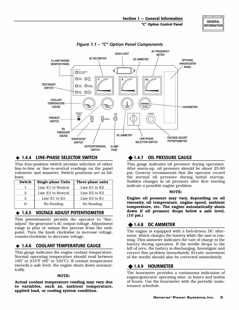
1.4.1 AC VOLTMETERThis meter indicates the generator AC output voltage.(Also see “Line-phase Selector Switch” and “VoltageAdjust Potentiometer” in this section). To determinethe nominal rated AC voltage of the unit, refer to theunit’s data plate.
NOTE:
Some generators are reconnectable to a variety ofvoltages. Some units may be equipped with arotary “Voltage Selector Switch.” Be sure to readthe “Generator AC Lead Connections” section inthe Owner’s Manual.
1.4.2 AC AMMETERThis meter indicates the current draw of connectedelectrical loads, in amps. (Also see “Line-phaseSelector Switch”). For continuous operation, neverexceed the rated maximum continuous currentcapacity of the generator.
1.4.3 FREQUENCY METERThis meter indicates the generator’s AC output fre-quency in “Hertz” (cycles per second).
◆
◆
◆
!
Section 1 — General Information“C” Option Control Panel
2 Generac® Power Systems, Inc.
Generac® Power Systems, Inc. 3
1.4.4 LINE-PHASE SELECTOR SWITCHThis four-position switch permits selection of eitherline-to-line or line-to-neutral readings on the panelvoltmeter and ammeter. Switch positions are as fol-lows:
1.4.5 VOLTAGE ADJUST POTENTIOMETERThis potentiometer permits the operator to “fine-adjust” the generator’s AC output voltage. Adjustmentrange is plus or minus five percent from the mid-point. Turn the knob clockwise to increase voltage,counterclockwise to decrease voltage.
1.4.6 COOLANT TEMPERATURE GAUGEThis gauge indicates the engine coolant temperature.Normal operating temperature should read between185° to 215°F (85° to 102°C). If coolant temperatureexceeds a safe level, the engine shuts down automat-ically.
NOTE:
Actual coolant temperature reading may vary dueto variables, such as, ambient temperature,applied load, or cooling system condition.
1.4.7 OIL PRESSURE GAUGEThis gauge indicates oil pressure during operation.After warm-up, oil pressure should be about 25-90psi. Generac recommends that the operator recordthe normal oil pressure during initial startup.Sudden changes in oil pressure after first startingindicate a possible engine problem.
NOTE:
Engine oil pressure may vary, depending on oilviscosity, oil temperature, engine speed, ambienttemperature, etc. The engine automatically shutsdown if oil pressure drops below a safe level. (10 psi.)
1.4.8 DC AMMETERThe engine is equipped with a belt-driven DC alter-nator, which charges the battery while the unit is run-ning. This ammeter indicates the rate of charge to thebattery during operation. If the needle drops to theleft of zero, the battery is discharging. Investigate andcorrect this problem immediately. Erratic movementof the needle should also be corrected immediately.
1.4.9 HOURMETERThe hourmeter provides a continuous indication ofengine/generator operating time, in hours and tenthsof hours. Use the hourmeter with the periodic main-tenance schedule.
◆
◆
◆
Section 1 — General Information“C” Option Control Panel
0
1
2
Figure 1.1 – “C” Option Panel Components
Switch Single-phase Units Three-phase units1 Line E1 to Neutral Line E1 to E2
2 Line E3 to Neutral Line E2 to E3
3 Line E1 to E3 Line E3 to E1
O No Reading No Reading
4 Generac® Power Systems, Inc.
1.4.10 START/STOP SWITCHUse this switch to crank and start the engine manu-ally, or to shut down an operating engine.
• To crank and start engine, first set theAuto/Off/Manual switch to its “Manual” position.
• Hold the Start/Stop switch at “Start.” When theengine starts, release the switch to its center (run)position.
• To shut engine down, move the switch to its “Stop”position.
1.4.11 AUTO/OFF/MANUAL SWITCHThis safety switch should be used to prevent auto-matic startup of the engine when working on theengine/generator. Use the switch as follows:
Auto PositionAlways set switch to AUTO for automatic systemoperation. This means that, when this generator isinstalled with a GTS-type automatic transfer switch,the generator automatically cranks and starts whenthe utility source voltage drops below a preset level,or the unit exercises, if programmed to do so.
Off PositionThe engine cannot be started either automatically ormanually. Always set switch to OFF before workingon, or around, the engine-generator.
Manual PositionThe engine can be cranked and started manuallyusing the panel Start/Stop switch. The engine will notstart automatically.
NOTE:
Also see “Engine Monitor Panel.” With switch setto either OFF or MANUAL, a “Not in AutomaticStart Mode” lamp lights up on the panel.
1.4.12 PANEL FUSEThis fuse protects the control console’s DC circuitsagainst overload. If the fuse element melts open dueto an overload, engine cranking and startup will notbe possible. Should fuse replacement become neces-sary, use only an identical fuse (part number022676).
1.5 ENGINE MONITOR PANELThis panel has five advisory shutdown lamps for sep-arate engine fault conditions, plus a “Not inAutomatic Start Mode” lamp. Cranking and startingwill not be possible while any one, or more, of enginefault conditions lamps is lit, with the exception of“Not in Auto” illuminated in the manual mode. Thefollowing apply:
• A “lamp ON” condition indicates that fault condi-tion has been “latched” by DC control/latch-crankcircuit board.
• If any one of the lamps is ON (fault conditionlatched), the engine cannot be cranked either man-ually or automatically.
• To unlatch a fault (that is, to turn a lamp OFF) andpermit cranking, push the Test/Reset switch in.The lamp will then go OFF, allowing for additionalcranking.
1.5.1 NOT IN AUTOMATIC START MODELAMP
This lamp comes ON to indicate that automatic start-up of the engine is not possible. The lamp lights upwhenever the Auto/Off/Manual switch is set to OFF orMANUAL.
1.5.2 OVERCRANK LAMPThe control console houses a DC control/latch-crankcircuit board (the “C” board) that controls enginestartup and shutdown. During automatic startup, theengine cranks for about 14 seconds, rests for abouteight seconds, and so on, until eight crank-rest cycleshave occurred. At the end of eight attempts, crankingstops, and the overcrank lamp goes ON.
1.5.3 HIGH COOLANT TEMPERATURE LAMPThis lamp comes ON if coolant temperature is toohigh or coolant level is too low. The engine shutsdown automatically when such unsafe conditionsoccur. The following apply:
• If the engine is started with an existing high coolanttemperature or low coolant level condition, theengine shuts down, and the lamp comes ON whenengine speed reaches about 1000 rpm.
• If the engine starts normally but high tempera-ture/low coolant level develops later, the engineshuts down, and the light comes ON immediately.
1.5.4 OVERSPEED LAMPAn engine overspeed above a safe limit causes theengine to automatically shut down, which turns ONthe indicator lamp. The overspeed lamp comes onwhen the unit is run at a 15% faster rpm than rated.
◆
◆
◆
◆
◆
▼▼
▼
◆
◆
Section 1 — General Information“C” Option Control Panel
Generac® Power Systems, Inc. 5
1.5.5 LOW OIL PRESSURE LAMPThis lamp lights up (latches) to indicate low oil pres-sure in the engine as follows:
• During cranking, after engine has reached 800 to1000 rpm, the circuit allows four seconds for oilpressure to build.
• In auto mode, if the unit runs above 800-1000 rpmfor more than four seconds, and oil pressure isbelow a safe level, the engine shuts down, but thelamp does NOT go ON. The system then actuateseight restart attempts; the engine shuts down, andthe lamp goes ON.
• If the engine starts normally with good oil pres-sure, but oil pressure drops later, the system waitsfive seconds for oil pressure to be restored. If pres-sure is still low after a five-second delay, the engineshuts down, and the lamp goes ON immediately.
1.5.6 RPM SENSOR LOSS LAMPUnits with the “C” Option console are equipped withan rpm sensor, which is mounted directly over theengine flywheel gear teeth. This sensor is a magneticpickup that emits an electrical pulse at the passage ofeach flywheel gear tooth. Sensor electrical signals areused by the DC control/latch-crank circuit board asengine speed (rpm) signals. The circuit board usesthese rpm signals (a) to establish a starter lockoutspeed, and (b) to shut down the engine if the engineruns too fast (overspeed). If the rpm signals to thecircuit board are lost, engine shutdown occurs, butthe lamp will not light, (i.e., the condition will notlatch), then, depending on whether the sensor signalloss occurred during a manual or an automatic startattempt, the following events occur:
Manual StartupIf the engine starts within two seconds after crankingbegins, shutdown occurs as soon as the Start/Stopswitch is released, but without a lamp ON condition(latching does not occur). If engine does not startwithin two seconds after cranking begins, which dis-ables starting, the rpm sensor loss light goes ON.
Automatic StartupThe engine recranks within about one second after ithas stopped. If sensor loss persists, engine shutsdown, and lamp lights about two seconds aftercranking has restarted.
If engine starts within two seconds after recrank hasbegun, the starter remains engaged until the two-sec-ond delay is over.
1.5.7 TEST/RESET SWITCHTo test all lamps, push this switch in. Following anyfault shutdown with any monitor panel lamp illumi-nated, engine cranking is inhibited. To reset the sys-tem (unlatch a fault) and crank the engine again,push the switch in (lamp must go out). If the switchis actuated with the engine running, only the lampswill be tested. The engine will not shut down.
NOTE:
If engine shuts down due to some unmonitoredproblem (such as, out of fuel or failed ignition sys-tem), none of the lamps will come ON. If such anunmonitored shutdown occurs with theAuto/Off/Manual switch set to AUTO, enginerecranks and attempts to start for any of the cyclesremaining in the eight-crank limit. After all eightcrank cycles have been used, the engine shutsdown, and the OVERCRANK lamp goes ON.
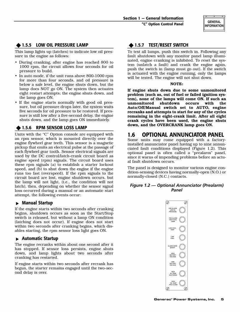
1.6 OPTIONAL ANNUNCIATOR PANELSome units may come equipped with a factory-installed annunciator panel having up to nine annun-ciated fault conditions displayed (Figure 1.2). Thisoptional panel is often called a “prealarm” panel,since it warns of impending problems before an actu-al fault shutdown occurs.
The panel is designed to monitor various engine con-dition-sensing devices having normally-open (N.O.) ornormally-closed (N.C.) contacts.
Figure 1.2 — Optional Annunciator (Prealarm)Panel
ALARM HORNON/OFF
LOWFUEL
LOW COOLTEMP
HIGHBATTERYVOLTAGE
LOWBATTERYVOLTAGE
HIGHOIL TEMP
SHUTDOWN
HIGHOIL TEMP
PRE-ALARM
PRE-ALARMLOW OIL
PRESSURE
PRE-ALARMHIGH COOL
TEMP
◆
▼▼
◆
◆
Section 1 — General Information“C” Option Control Panel
6 Generac® Power Systems, Inc.
1.7 OPTIONAL REMOTEANNUNCIATOR
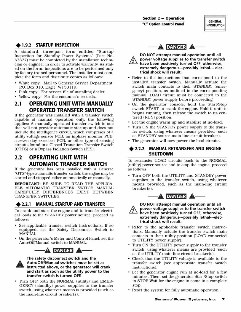
An optional 18-light REMOTE annunciator panel thatcan be mounted on a wall (Figure 1.3) is also avail-able. For information on the remote annunciator pan-els, ask the local dealer/distributor or consult the fac-tory. Ask for information on the Models 9555 and9556 remote annunciator panels. The following applyto the remote annunciator panels:
• It is designed for use with installation having aGenerac Power Systems GTS-type transfer switchand a “C” Option control panel.
• The panel is available in both flush-mounted(Model 9556) and surface-mounted (Model 9555)configurations.
• The panel has a built-in audible alarm horn, with areset switch to turn off the horn without disturbingthe lighted indication.
• Remote monitoring of the standby generator setprovides enough information to avoid unnecessarymaintenance trips to the generator site.
Figure 1.3 — Optional 18-Light RemoteAnnunciator
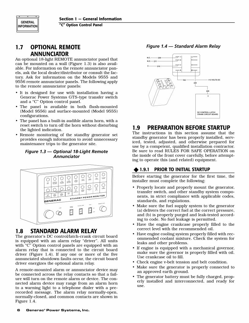
1.8 STANDARD ALARM RELAYThe generator’s DC control/latch-crank circuit boardis equipped with an alarm relay “driver”. All unitswith “C” Option control panels are equipped with analarm relay that is connected to the circuit boarddriver (Figure 1.4). If any one or more of the fiveannunciated shutdown faults occur, the circuit boarddriver energizes the optional alarm relay.
A remote-mounted alarm or annunciator device maybe connected across the relay contacts so that a fail-ure will turn on the remote alarm or device. The con-nected alarm device may range from an alarm hornto a warning light to a telephone dialer with a pre-recorded message. The alarm relay normally-open,normally-closed, and common contacts are shown inFigure 1.4.
Figure 1.4 — Standard Alarm Relay
1.9 PREPARATION BEFORE STARTUPThe instructions in this section assume that thestandby generator has been properly installed, serv-iced, tested, adjusted, and otherwise prepared foruse by a competent, qualified installation contractor.Be sure to read RULES FOR SAFE OPERATION onthe inside of the front cover carefully, before attempt-ing to operate this (and related) equipment.
1.9.1 PRIOR TO INITIAL STARTUPBefore starting the generator for the first time, theinstaller must complete the following:
• Properly locate and properly mount the generator,transfer switch, and other standby system compo-nents, in strict compliance with applicable codes,standards, and regulations.
• Make sure the fuel supply system to the generator(a) delivers the correct fuel at the correct pressure,and (b) is properly purged and leak-tested accord-ing to code. No fuel leakage is permitted.
• Have the engine crankcase properly filled to thecorrect level with the recommended oil.
• Have engine cooling system properly filled with rec-ommended coolant mixture. Check the system forleaks and other problems.
• If engine is equipped with a mechanical governor,make sure the governor is properly filled with oil.Use crankcase oil to fill.
• Check engine v-belt tension and belt condition.• Make sure the generator is properly connected to
an approved earth ground.• The generator battery must be fully charged, prop-
erly installed and interconnected, and ready foruse.
◆
Section 1 — General Information“C” Option Control Panel
Generac® Power Systems, Inc. 7
1.9.2 STARTUP INSPECTIONA standard, three-part form entitled “StartupInspection for Standby Power Systems” (Part No.67377) must be completed by the installation techni-cian or engineer in order to activate warranty. As stat-ed on the form, inspections are to be performed onlyby factory-trained personnel. The installer must com-plete the form and distribute copies as follows:
• White copy: Mail to Generac Service Department,P.O. Box 310, Eagle, WI 53119.
• Pink copy: For service file of installing dealer.• Yellow copy: For the customer’s records.
2.1 OPERATING UNIT WITH MANUALLYOPERATED TRANSFER SWITCH
If the generator was installed with a transfer switchcapable of manual operation only, the followingapplies: A manually-operated transfer switch is onethat will not provide automatic startup and does notinclude the intelligence circuit, which comprises of autility voltage sensor PCB, an inphase monitor PCB,a seven day exerciser PCB, or other type of sensingcircuits found in a Closed Transition Transfer Switch(CTTS) or a Bypass Isolation Switch (BIS).
2.2 OPERATING UNIT WITHAUTOMATIC TRANSFER SWITCH
If the generator has been installed with a Generac“GTS”-type automatic transfer switch, the engine may bestarted and stopped either automatically or manually.
IMPORTANT: BE SURE TO READ THE APPLICA-BLE AUTOMATIC TRANSFER SWITCH MANUALCAREFULLY. DIFFERENCES EXIST BETWEENTRANSFER SWITCHES.
2.2.1 MANUAL STARTUP AND TRANSFERTo crank and start the engine and to transfer electri-cal loads to the STANDBY power source, proceed asfollows:
• See applicable transfer switch instructions. If soequipped, set the Safety Disconnect Switch toMANUAL.
• On the generator’s Meter and Control Panel, set theAuto/Off/Manual switch to MANUAL.
The safety disconnect switch and theAuto/Off/Manual switches must be set asinstructed above, or the generator will crankand start as soon as the utility power to thetransfer switch is turned OFF.
• Turn OFF both the NORMAL (utility) and EMER-GENCY (standby) power supplies to the transferswitch, using whatever means is provided (such asthe main-line circuit breaker(s).
DO NOT attempt manual operation until allpower voltage supplies to the transfer switchhave been positively turned OFF; otherwise,extremely dangerous---possibly lethal--- elec-trical shock will result.
• Refer to the instructions that correspond to theinstalled transfer switch. Manually actuate theswitch main contacts to their STANDBY (emer-gency) position, as outlined in the correspondingmanual. LOAD circuit must be connected to theSTANDBY power supply before proceeding.
• On the generator console, hold the Start/Stopswitch START to crank the engine. Hold it until itbegins running, then release the switch to its cen-tered (RUN) position.
• Let the engine warm up and stabilize at no-load.• Turn ON the STANDBY power supply to the trans-
fer switch, using whatever means provided (suchas STANDBY source main-line circuit breaker).
• The generator will now power the load circuits.
2.2.2 MANUAL RETRANSFER AND ENGINE SHUTDOWN
To retransfer LOAD circuits back to the NORMAL(utility) power source and to stop the engine, proceedas follows:
• Turn OFF both the UTILITY and STANDBY powersupplies to the transfer switch, using whatevermeans provided, such as the main-line circuitbreaker(s).
DO NOT attempt manual operation until allpower voltage supplies to the transfer switchhave been positively turned OFF; otherwise,extremely dangerous---possibly lethal---elec-trical shock will result.
• Refer to the applicable transfer switch instruc-tions. Manually actuate the transfer switch maincontacts to their utility position (LOAD connectedto UTILITY power supply).
• Turn ON the UTILITY power supply to the transferswitch, using whatever means are provided (suchas the UTILITY main-line circuit breaker(s).
• Check that the UTILITY voltage is available to thetransfer switch (see appropriate transfer switchinstructions).
• Let the generator engine run at no-load for a fewminutes. Then, set the generator Start/Stop switchto STOP. Wait for the engine to come to a completestop.
• Reset the system for fully automatic operation.
DANGER
◆
DANGER
!
DANGER
◆
◆
Section 2 — Operation“C” Option Control Panel
8 Generac® Power Systems, Inc.
2.2.3 PREVENTING AUTOMATIC STARTUP
When installed with an automatic transferswitch, Generac standby generators can crankand start suddenly, without warning, whenUTILITY source voltage drops below a presetvalue. To prevent possible injuries caused bysuch sudden starts, disable the automatictransfer switch before working on, or around,the generator. Use any one, or more, of the fol-lowing methods to disable the automatic startfunction:
• Set the generator’s Auto/Off/Manual switch to OFF.Neither a manual nor an automatic start can beaccomplished with this switch set to OFF.
• Remove the fuse from the generator control panel.To remove the fuse, push fuse holder cap in andturn cap counterclockwise. Remove cap and fuseelement.
• Refer to the automatic transfer switch instructions.If the transfer switch is so equipped, set its SafetyDisconnect switch to MANUAL position to preventautomatic startup and transfer.
• Disconnect battery cable from generator batterypost, indicated by a negative, NEG, or (-).
!
DANGER
◆
Section 2 — Operation“C” Option Control Panel
Generac® Power Systems, Inc. 9
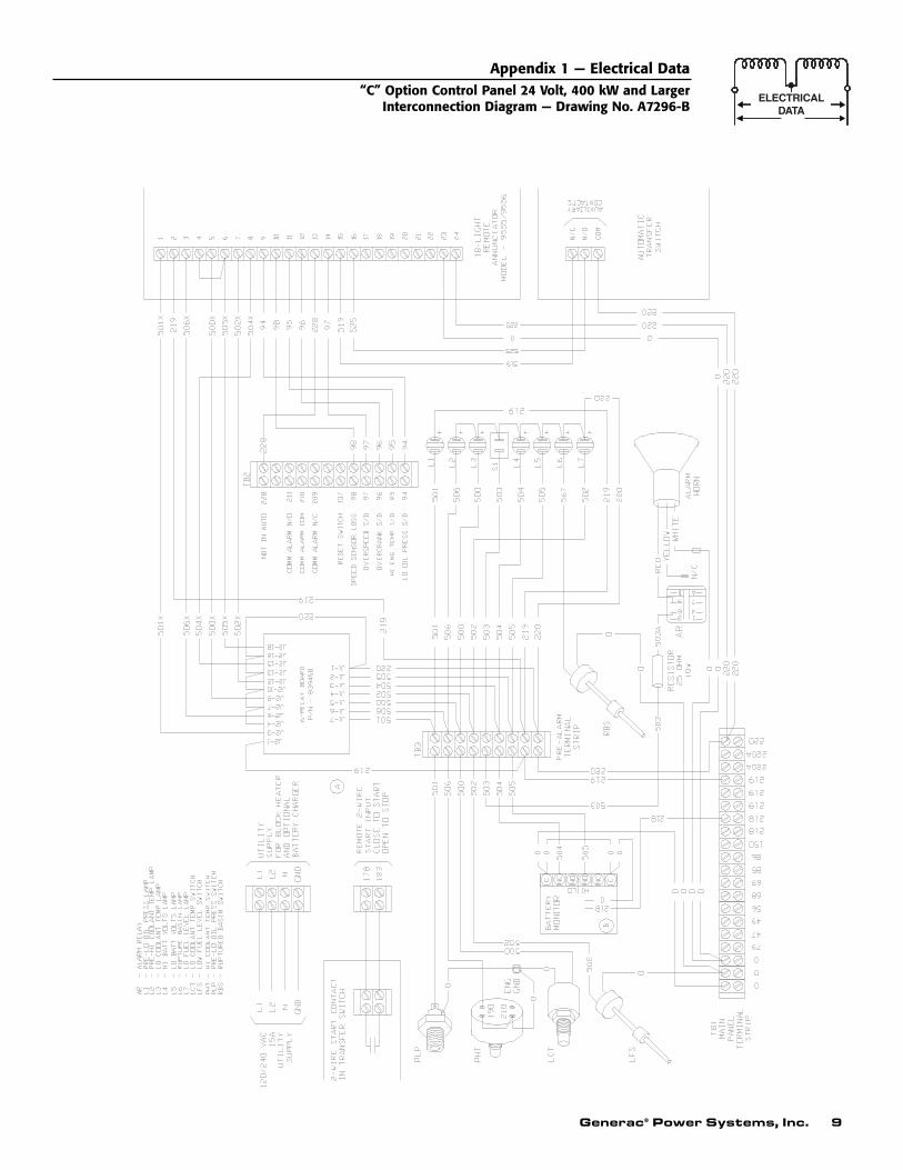
Appendix 1 — Electrical Data“C” Option Control Panel 24 Volt, 400 kW and Larger
Interconnection Diagram — Drawing No. A7296-B
10 Generac® Power Systems, Inc.
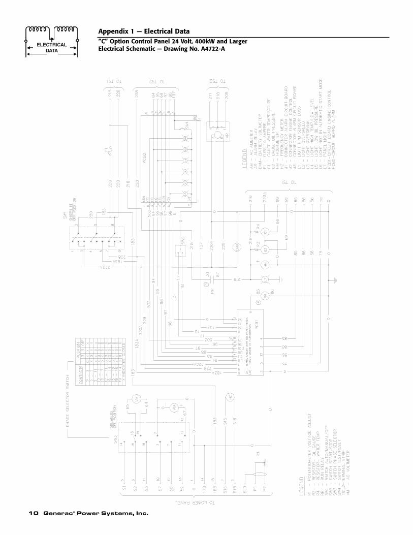
Appendix 1 — Electrical Data“C” Option Control Panel 24 Volt, 400kW and LargerElectrical Schematic — Drawing No. A4722-A
Generac® Power Systems, Inc. 11
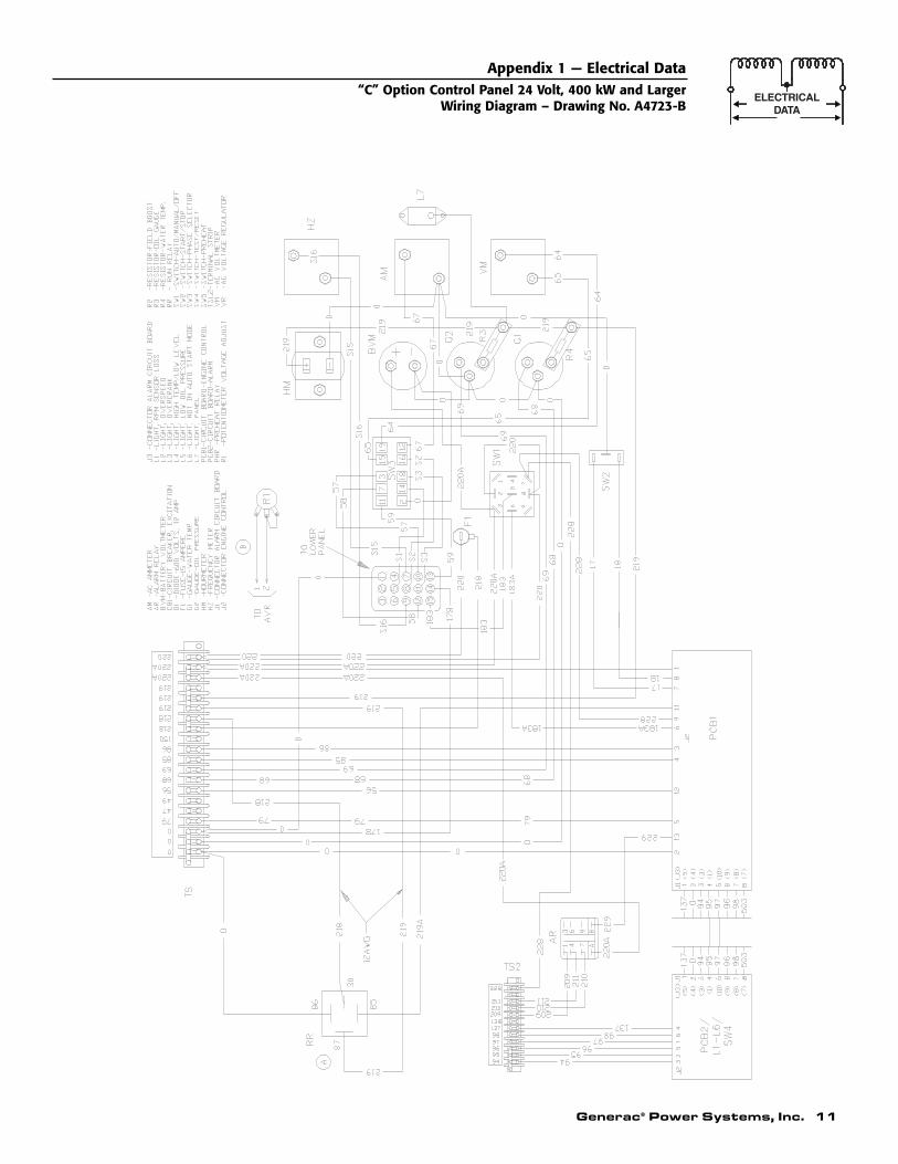
Appendix 1 — Electrical Data“C” Option Control Panel 24 Volt, 400 kW and Larger
Wiring Diagram – Drawing No. A4723-B
12 Generac® Power Systems, Inc.
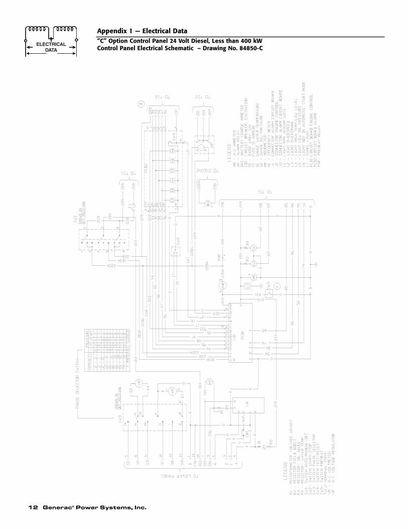
Appendix 1 — Electrical Data“C” Option Control Panel 24 Volt Diesel, Less than 400 kWControl Panel Electrical Schematic – Drawing No. 84850-C
Generac® Power Systems, Inc. 13
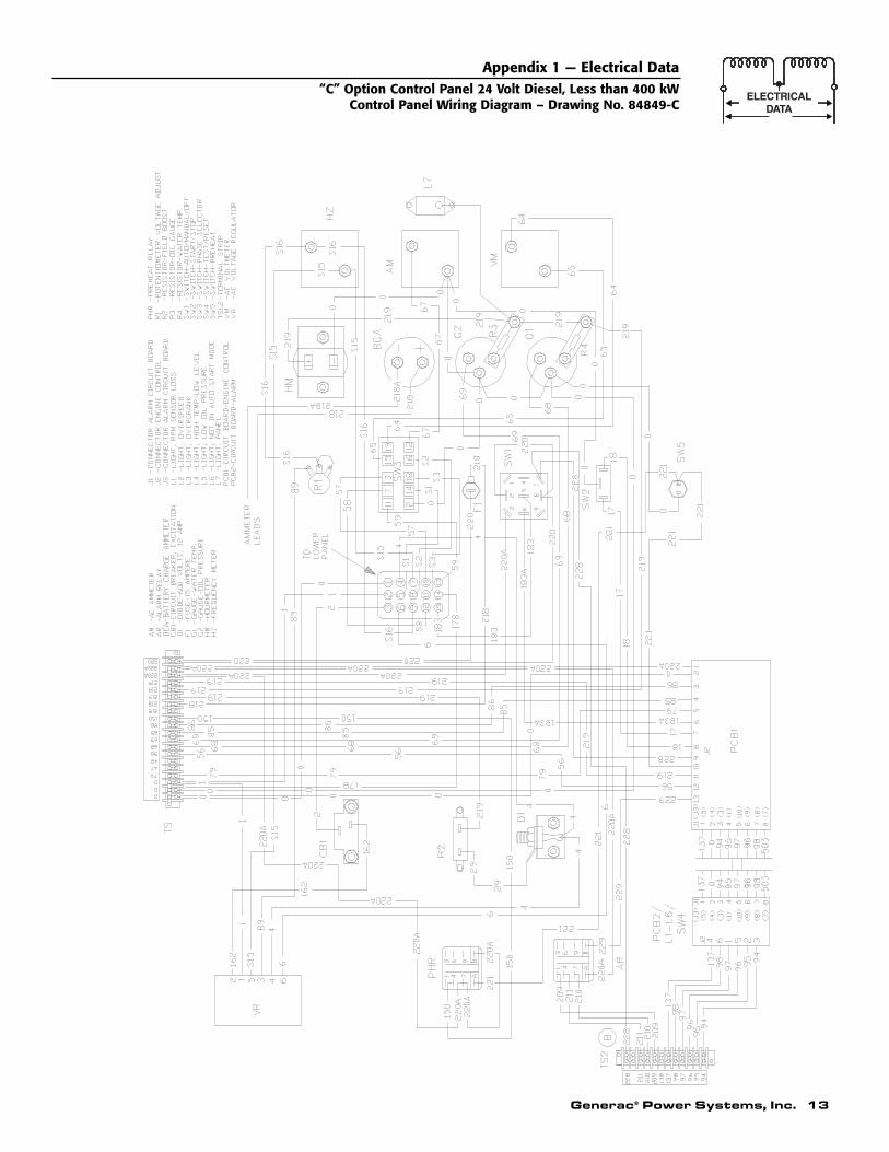
Appendix 1 — Electrical Data“C” Option Control Panel 24 Volt Diesel, Less than 400 kW
Control Panel Wiring Diagram – Drawing No. 84849-C
14 Generac® Power Systems, Inc.
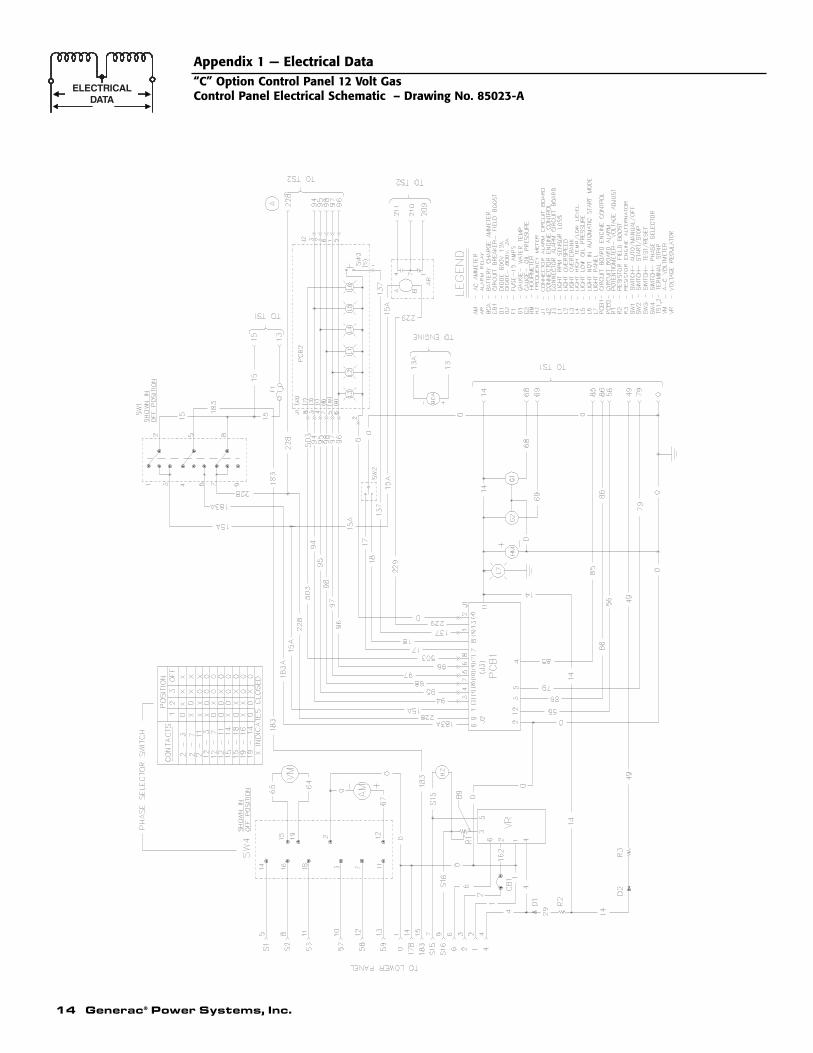
Appendix 1 — Electrical Data“C” Option Control Panel 12 Volt GasControl Panel Electrical Schematic – Drawing No. 85023-A
Generac® Power Systems, Inc. 15
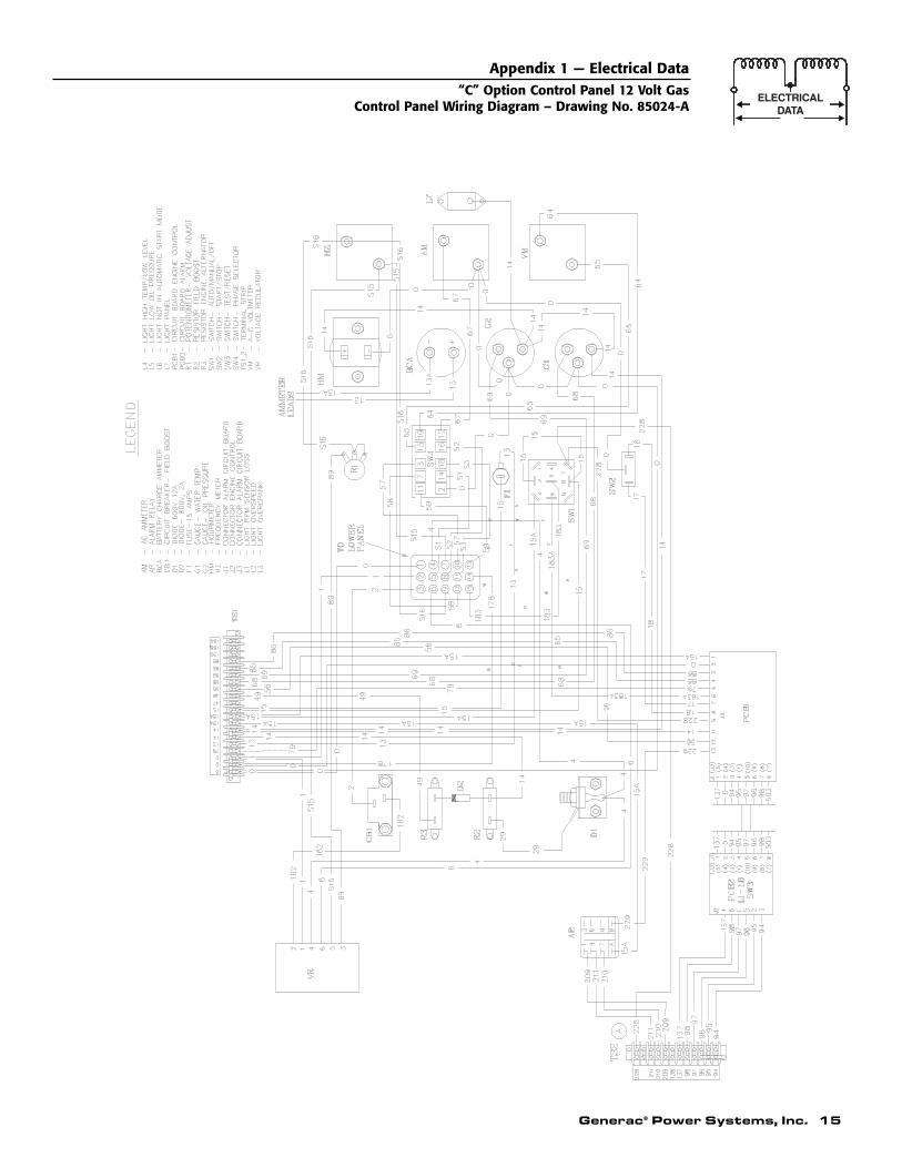
Appendix 1 — Electrical Data“C” Option Control Panel 12 Volt Gas
Control Panel Wiring Diagram – Drawing No. 85024-A
9
27 24 22 21
1113
59
6660
57
3
5859
25
MIC
A
6412
16155
6256
4
5758
77
7226
53
A
73
68646
68
78
26
10
2653
141718
2626
18D
7
23
519
59
1717
7715
70
VIE
W
42
7
A4 71
B
A
6 93
202
60 66
958
4041
29 2830
39- +
37
63
5145
5253
54
8 35163643
65
3433
5844
5960
6631
57
26
00
16 Generac® Power Systems, Inc.
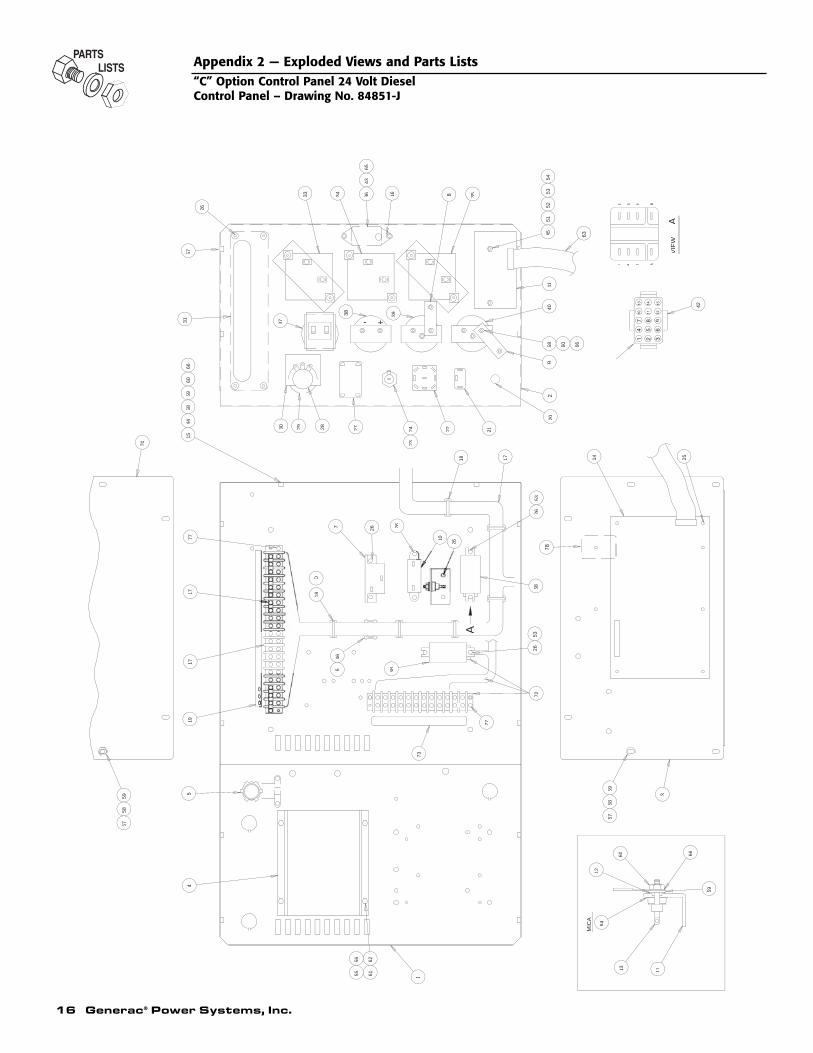
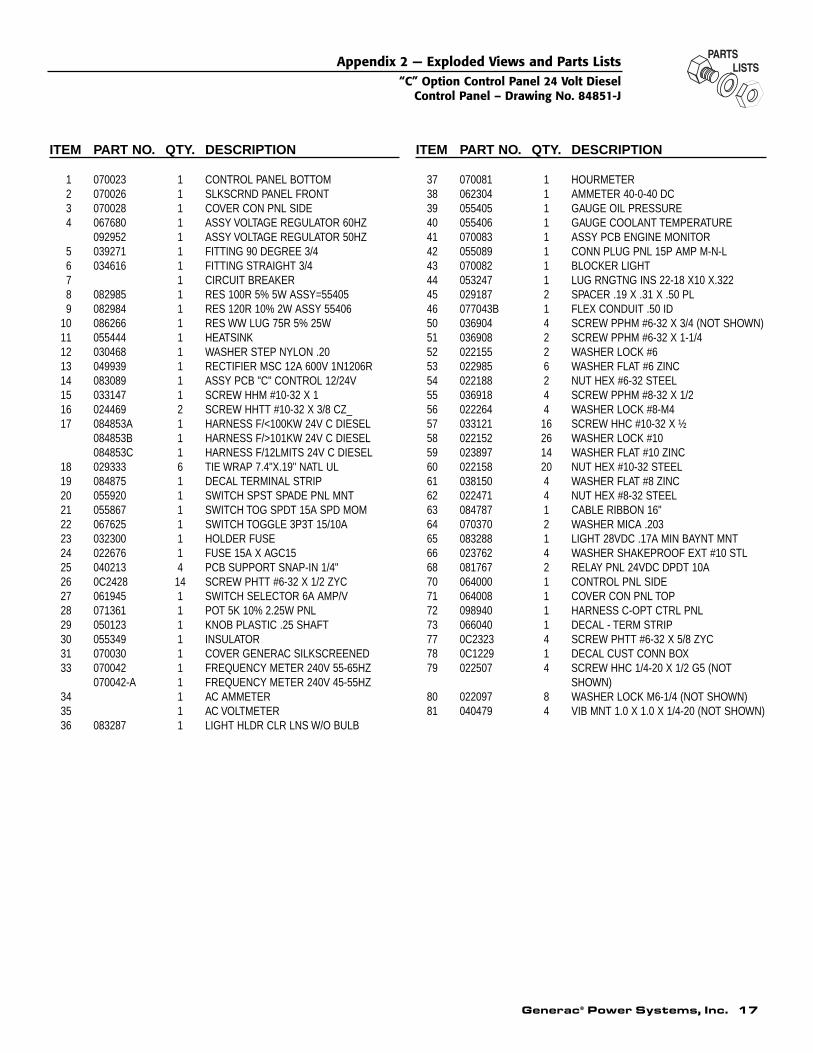
Appendix 2 — Exploded Views and Parts Lists“C” Option Control Panel 24 Volt DieselControl Panel – Drawing No. 84851-J
Generac® Power Systems, Inc. 17
ITEM PART NO. QTY. DESCRIPTION
1 070023 1 CONTROL PANEL BOTTOM2 070026 1 SLKSCRND PANEL FRONT3 070028 1 COVER CON PNL SIDE4 067680 1 ASSY VOLTAGE REGULATOR 60HZ
092952 1 ASSY VOLTAGE REGULATOR 50HZ5 039271 1 FITTING 90 DEGREE 3/46 034616 1 FITTING STRAIGHT 3/47 1 CIRCUIT BREAKER8 082985 1 RES 100R 5% 5W ASSY=554059 082984 1 RES 120R 10% 2W ASSY 55406
10 086266 1 RES WW LUG 75R 5% 25W11 055444 1 HEATSINK12 030468 1 WASHER STEP NYLON .2013 049939 1 RECTIFIER MSC 12A 600V 1N1206R14 083089 1 ASSY PCB "C" CONTROL 12/24V15 033147 1 SCREW HHM #10-32 X 116 024469 2 SCREW HHTT #10-32 X 3/8 CZ_17 084853A 1 HARNESS F/<100KW 24V C DIESEL
084853B 1 HARNESS F/>101KW 24V C DIESEL084853C 1 HARNESS F/12LMITS 24V C DIESEL
18 029333 6 TIE WRAP 7.4"X.19" NATL UL19 084875 1 DECAL TERMINAL STRIP20 055920 1 SWITCH SPST SPADE PNL MNT21 055867 1 SWITCH TOG SPDT 15A SPD MOM22 067625 1 SWITCH TOGGLE 3P3T 15/10A23 032300 1 HOLDER FUSE24 022676 1 FUSE 15A X AGC1525 040213 4 PCB SUPPORT SNAP-IN 1/4"26 0C2428 14 SCREW PHTT #6-32 X 1/2 ZYC27 061945 1 SWITCH SELECTOR 6A AMP/V28 071361 1 POT 5K 10% 2.25W PNL29 050123 1 KNOB PLASTIC .25 SHAFT30 055349 1 INSULATOR31 070030 1 COVER GENERAC SILKSCREENED33 070042 1 FREQUENCY METER 240V 55-65HZ
070042-A 1 FREQUENCY METER 240V 45-55HZ34 1 AC AMMETER35 1 AC VOLTMETER36 083287 1 LIGHT HLDR CLR LNS W/O BULB
ITEM PART NO. QTY. DESCRIPTION
37 070081 1 HOURMETER38 062304 1 AMMETER 40-0-40 DC39 055405 1 GAUGE OIL PRESSURE40 055406 1 GAUGE COOLANT TEMPERATURE41 070083 1 ASSY PCB ENGINE MONITOR42 055089 1 CONN PLUG PNL 15P AMP M-N-L43 070082 1 BLOCKER LIGHT44 053247 1 LUG RNGTNG INS 22-18 X10 X.32245 029187 2 SPACER .19 X .31 X .50 PL46 077043B 1 FLEX CONDUIT .50 ID50 036904 4 SCREW PPHM #6-32 X 3/4 (NOT SHOWN) 51 036908 2 SCREW PPHM #6-32 X 1-1/452 022155 2 WASHER LOCK #653 022985 6 WASHER FLAT #6 ZINC54 022188 2 NUT HEX #6-32 STEEL55 036918 4 SCREW PPHM #8-32 X 1/256 022264 4 WASHER LOCK #8-M457 033121 16 SCREW HHC #10-32 X ½58 022152 26 WASHER LOCK #1059 023897 14 WASHER FLAT #10 ZINC60 022158 20 NUT HEX #10-32 STEEL61 038150 4 WASHER FLAT #8 ZINC62 022471 4 NUT HEX #8-32 STEEL63 084787 1 CABLE RIBBON 16"64 070370 2 WASHER MICA .20365 083288 1 LIGHT 28VDC .17A MIN BAYNT MNT66 023762 4 WASHER SHAKEPROOF EXT #10 STL68 081767 2 RELAY PNL 24VDC DPDT 10A70 064000 1 CONTROL PNL SIDE71 064008 1 COVER CON PNL TOP72 098940 1 HARNESS C-OPT CTRL PNL73 066040 1 DECAL - TERM STRIP77 0C2323 4 SCREW PHTT #6-32 X 5/8 ZYC78 0C1229 1 DECAL CUST CONN BOX79 022507 4 SCREW HHC 1/4-20 X 1/2 G5 (NOT
SHOWN)80 022097 8 WASHER LOCK M6-1/4 (NOT SHOWN)81 040479 4 VIB MNT 1.0 X 1.0 X 1/4-20 (NOT SHOWN)
Appendix 2 — Exploded Views and Parts Lists“C” Option Control Panel 24 Volt Diesel
Control Panel – Drawing No. 84851-J
18 Generac® Power Systems, Inc.
7
15
17
31
32
55
5845
56
11 12 13
3534
64
26
212224
5152
5453
23
220
40
27282930
54
1
62
3347
49
56
6156
15
57
49
46
5661
42
38
37
39
5958
57
14 25
3
5859
19
43
67
8
41
65
66
9
63
60 69
70
59
69
72
7173
60
5
4956
6110
4458
60
5759
81
INS
TA
LLA
TIO
N O
F W
IRE
HA
RN
ES
S A
SM
.S
EE
WIR
ING
DIA
GR
AM
#84
673
FO
R
1310
7
A
3 6 9
A
41 A7
B
VIE
W
219
A
31
219
+-
(2-P
LCS
)M
ICA
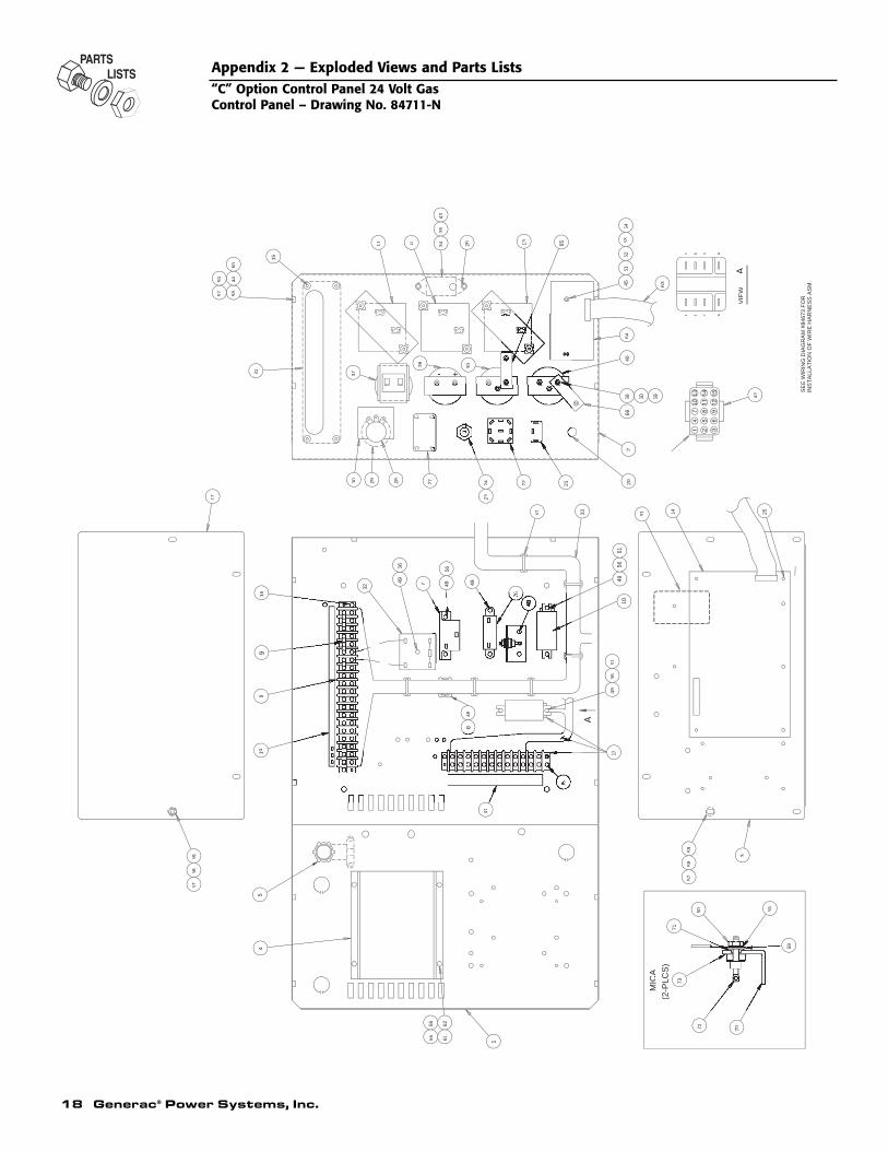
Appendix 2 — Exploded Views and Parts Lists“C” Option Control Panel 24 Volt GasControl Panel – Drawing No. 84711-N
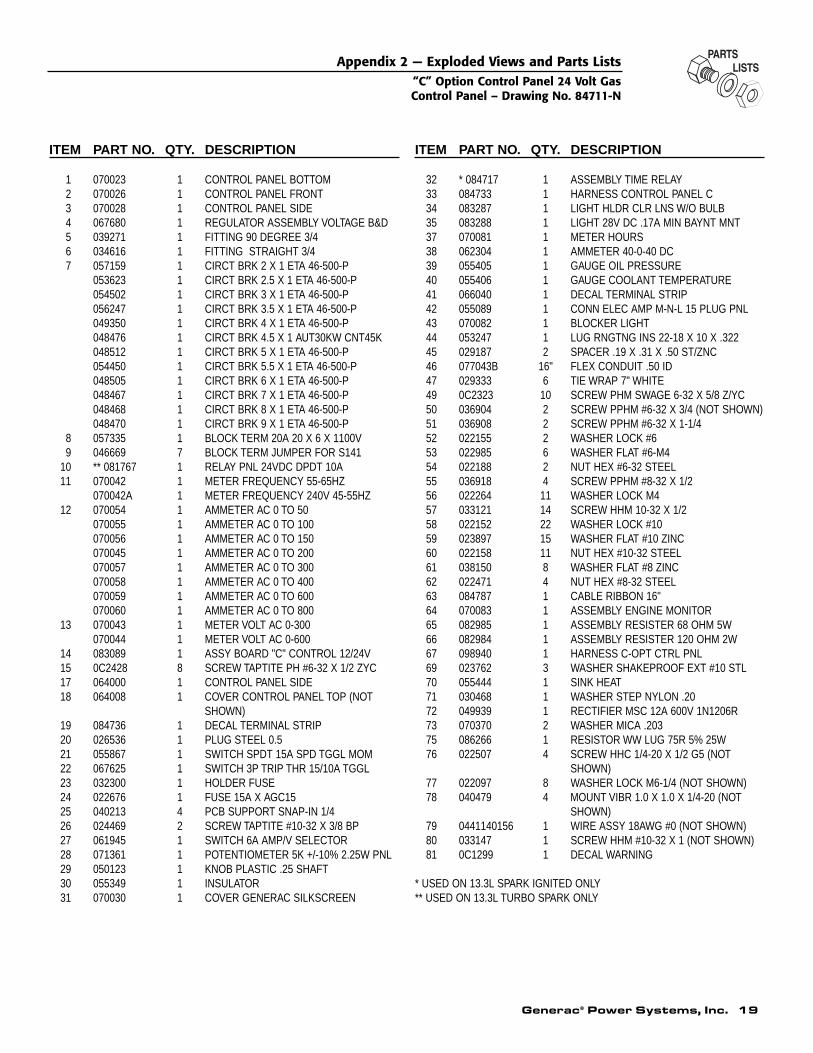
Generac® Power Systems, Inc. 19
ITEM PART NO. QTY. DESCRIPTION
1 070023 1 CONTROL PANEL BOTTOM2 070026 1 CONTROL PANEL FRONT3 070028 1 CONTROL PANEL SIDE4 067680 1 REGULATOR ASSEMBLY VOLTAGE B&D5 039271 1 FITTING 90 DEGREE 3/46 034616 1 FITTING STRAIGHT 3/47 057159 1 CIRCT BRK 2 X 1 ETA 46-500-P
053623 1 CIRCT BRK 2.5 X 1 ETA 46-500-P054502 1 CIRCT BRK 3 X 1 ETA 46-500-P056247 1 CIRCT BRK 3.5 X 1 ETA 46-500-P049350 1 CIRCT BRK 4 X 1 ETA 46-500-P048476 1 CIRCT BRK 4.5 X 1 AUT30KW CNT45K048512 1 CIRCT BRK 5 X 1 ETA 46-500-P054450 1 CIRCT BRK 5.5 X 1 ETA 46-500-P048505 1 CIRCT BRK 6 X 1 ETA 46-500-P048467 1 CIRCT BRK 7 X 1 ETA 46-500-P048468 1 CIRCT BRK 8 X 1 ETA 46-500-P048470 1 CIRCT BRK 9 X 1 ETA 46-500-P
8 057335 1 BLOCK TERM 20A 20 X 6 X 1100V9 046669 7 BLOCK TERM JUMPER FOR S141
10 ** 081767 1 RELAY PNL 24VDC DPDT 10A11 070042 1 METER FREQUENCY 55-65HZ
070042A 1 METER FREQUENCY 240V 45-55HZ12 070054 1 AMMETER AC 0 TO 50
070055 1 AMMETER AC 0 TO 100070056 1 AMMETER AC 0 TO 150070045 1 AMMETER AC 0 TO 200070057 1 AMMETER AC 0 TO 300070058 1 AMMETER AC 0 TO 400070059 1 AMMETER AC 0 TO 600070060 1 AMMETER AC 0 TO 800
13 070043 1 METER VOLT AC 0-300070044 1 METER VOLT AC 0-600
14 083089 1 ASSY BOARD "C" CONTROL 12/24V15 0C2428 8 SCREW TAPTITE PH #6-32 X 1/2 ZYC17 064000 1 CONTROL PANEL SIDE18 064008 1 COVER CONTROL PANEL TOP (NOT
SHOWN)19 084736 1 DECAL TERMINAL STRIP20 026536 1 PLUG STEEL 0.521 055867 1 SWITCH SPDT 15A SPD TGGL MOM22 067625 1 SWITCH 3P TRIP THR 15/10A TGGL23 032300 1 HOLDER FUSE24 022676 1 FUSE 15A X AGC1525 040213 4 PCB SUPPORT SNAP-IN 1/4 26 024469 2 SCREW TAPTITE #10-32 X 3/8 BP27 061945 1 SWITCH 6A AMP/V SELECTOR28 071361 1 POTENTIOMETER 5K +/-10% 2.25W PNL29 050123 1 KNOB PLASTIC .25 SHAFT30 055349 1 INSULATOR31 070030 1 COVER GENERAC SILKSCREEN
ITEM PART NO. QTY. DESCRIPTION
32 * 084717 1 ASSEMBLY TIME RELAY33 084733 1 HARNESS CONTROL PANEL C34 083287 1 LIGHT HLDR CLR LNS W/O BULB35 083288 1 LIGHT 28V DC .17A MIN BAYNT MNT37 070081 1 METER HOURS38 062304 1 AMMETER 40-0-40 DC39 055405 1 GAUGE OIL PRESSURE40 055406 1 GAUGE COOLANT TEMPERATURE41 066040 1 DECAL TERMINAL STRIP42 055089 1 CONN ELEC AMP M-N-L 15 PLUG PNL43 070082 1 BLOCKER LIGHT44 053247 1 LUG RNGTNG INS 22-18 X 10 X .32245 029187 2 SPACER .19 X .31 X .50 ST/ZNC46 077043B 16" FLEX CONDUIT .50 ID47 029333 6 TIE WRAP 7" WHITE49 0C2323 10 SCREW PHM SWAGE 6-32 X 5/8 Z/YC50 036904 2 SCREW PPHM #6-32 X 3/4 (NOT SHOWN)51 036908 2 SCREW PPHM #6-32 X 1-1/452 022155 2 WASHER LOCK #653 022985 6 WASHER FLAT #6-M454 022188 2 NUT HEX #6-32 STEEL55 036918 4 SCREW PPHM #8-32 X 1/256 022264 11 WASHER LOCK M457 033121 14 SCREW HHM 10-32 X 1/258 022152 22 WASHER LOCK #1059 023897 15 WASHER FLAT #10 ZINC60 022158 11 NUT HEX #10-32 STEEL61 038150 8 WASHER FLAT #8 ZINC62 022471 4 NUT HEX #8-32 STEEL63 084787 1 CABLE RIBBON 16"64 070083 1 ASSEMBLY ENGINE MONITOR65 082985 1 ASSEMBLY RESISTER 68 OHM 5W66 082984 1 ASSEMBLY RESISTER 120 OHM 2W67 098940 1 HARNESS C-OPT CTRL PNL69 023762 3 WASHER SHAKEPROOF EXT #10 STL70 055444 1 SINK HEAT71 030468 1 WASHER STEP NYLON .2072 049939 1 RECTIFIER MSC 12A 600V 1N1206R73 070370 2 WASHER MICA .20375 086266 1 RESISTOR WW LUG 75R 5% 25W76 022507 4 SCREW HHC 1/4-20 X 1/2 G5 (NOT
SHOWN)77 022097 8 WASHER LOCK M6-1/4 (NOT SHOWN)78 040479 4 MOUNT VIBR 1.0 X 1.0 X 1/4-20 (NOT
SHOWN)79 0441140156 1 WIRE ASSY 18AWG #0 (NOT SHOWN)80 033147 1 SCREW HHM #10-32 X 1 (NOT SHOWN)81 0C1299 1 DECAL WARNING
* USED ON 13.3L SPARK IGNITED ONLY** USED ON 13.3L TURBO SPARK ONLY
Appendix 2 — Exploded Views and Parts Lists“C” Option Control Panel 24 Volt GasControl Panel – Drawing No. 84711-N
20 Generac® Power Systems, Inc.
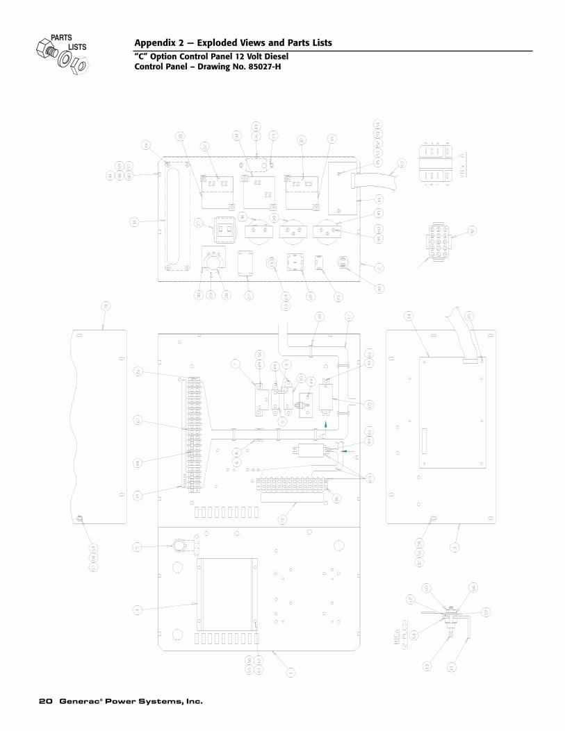
Appendix 2 — Exploded Views and Parts Lists“C” Option Control Panel 12 Volt DieselControl Panel – Drawing No. 85027-H
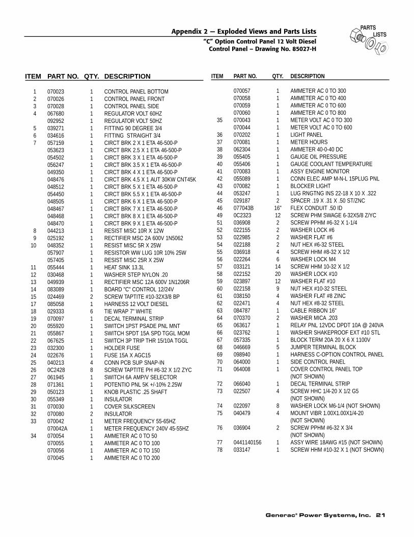
Generac® Power Systems, Inc. 21
ITEM PART NO. QTY. DESCRIPTION
1 070023 1 CONTROL PANEL BOTTOM2 070026 1 CONTROL PANEL FRONT3 070028 1 CONTROL PANEL SIDE4 067680 1 REGULATOR VOLT 60HZ
092952 1 REGULATOR VOLT 50HZ5 039271 1 FITTING 90 DEGREE 3/46 034616 1 FITTING STRAIGHT 3/47 057159 1 CIRCT BRK 2 X 1 ETA 46-500-P
053623 1 CIRCT BRK 2.5 X 1 ETA 46-500-P054502 1 CIRCT BRK 3 X 1 ETA 46-500-P056247 1 CIRCT BRK 3.5 X 1 ETA 46-500-P049350 1 CIRCT BRK 4 X 1 ETA 46-500-P048476 1 CIRCT BRK 4.5 X 1 AUT 30KW CNT45K048512 1 CIRCT BRK 5 X 1 ETA 46-500-P054450 1 CIRCT BRK 5.5 X 1 ETA 46-500-P048505 1 CIRCT BRK 6 X 1 ETA 46-500-P048467 1 CIRCT BRK 7 X 1 ETA 46-500-P048468 1 CIRCT BRK 8 X 1 ETA 46-500-P048470 1 CIRCT BRK 9 X 1 ETA 46-500-P
8 044213 1 RESIST MISC 10R X 12W9 025192 1 RECTIFIER MSC 2A 600V 1N5062
10 048352 1 RESIST MISC 5R X 25W057907 1 RESISTOR WW LUG 10R 10% 25W057405 1 RESIST MISC 25R X 25W
11 055444 1 HEAT SINK 13.3L12 030468 1 WASHER STEP NYLON .2013 049939 1 RECTIFIER MSC 12A 600V 1N1206R14 083089 1 BOARD "C" CONTROL 12/24V15 024469 2 SCREW TAPTITE #10-32X3/8 BP17 085058 1 HARNESS 12 VOLT DIESEL 18 029333 6 TIE WRAP 7" WHITE19 070097 1 DECAL TERMINAL STRIP20 055920 1 SWITCH 1PST PSADE PNL MNT21 055867 1 SWITCH SPDT 15A SPD TGGL MOM22 067625 1 SWITCH 3P TRIP THR 15/10A TGGL23 032300 1 HOLDER FUSE24 022676 1 FUSE 15A X AGC1525 040213 4 CONN PCB SUP SNAP-IN26 0C2428 8 SCREW TAPTITE PH #6-32 X 1/2 ZYC27 061945 1 SWITCH 6A AMP/V SELECTOR28 071361 1 POTENTIO PNL 5K +/-10% 2.25W29 050123 1 KNOB PLASTIC .25 SHAFT30 055349 1 INSULATOR31 070030 1 COVER SILKSCREEN32 070080 2 INSULATOR33 070042 1 METER FREQUENCY 55-65HZ
070042A 1 METER FREQUENCY 240V 45-55HZ34 070054 1 AMMETER AC 0 TO 50
070055 1 AMMETER AC 0 TO 100070056 1 AMMETER AC 0 TO 150070045 1 AMMETER AC 0 TO 200
ITEM PART NO. QTY. DESCRIPTION
070057 1 AMMETER AC 0 TO 300070058 1 AMMETER AC 0 TO 400070059 1 AMMETER AC 0 TO 600070060 1 AMMETER AC 0 TO 800
35 070043 1 METER VOLT AC 0 TO 300070044 1 METER VOLT AC 0 TO 600
36 070202 1 LIGHT PANEL37 070081 1 METER HOURS38 062304 1 AMMETER 40-0-40 DC39 055405 1 GAUGE OIL PRESSURE40 055406 1 GAUGE COOLANT TEMPERATURE41 070083 1 ASSY ENGINE MONITOR42 055089 1 CONN ELEC AMP M-N-L 15PLUG PNL43 070082 1 BLOCKER LIGHT44 053247 1 LUG RNGTNG INS 22-18 X 10 X .32245 029187 2 SPACER .19 X .31 X .50 ST/ZNC46 077043B 16" FLEX CONDUIT .50 ID49 0C2323 12 SCREW PHM SWAGE 6-32X5/8 Z/YC51 036908 2 SCREW PPHM #6-32 X 1-1/452 022155 2 WASHER LOCK #653 022985 2 WASHER FLAT #654 022188 2 NUT HEX #6-32 STEEL55 036918 4 SCREW HHM #8-32 X 1/256 022264 6 WASHER LOCK M457 033121 14 SCREW HHM 10-32 X 1/258 022152 20 WASHER LOCK #1059 023897 12 WASHER FLAT #1060 022158 9 NUT HEX #10-32 STEEL61 038150 4 WASHER FLAT #8 ZINC62 022471 4 NUT HEX #8-32 STEEL63 084787 1 CABLE RIBBON 16"64 070370 2 WASHER MICA .20365 063617 1 RELAY PNL 12VDC DPDT 10A @ 240VA66 023762 1 WASHER SHAKEPROOF EXT #10 STL67 057335 1 BLOCK TERM 20A 20 X 6 X 1100V68 046669 5 JUMPER TERMINAL BLOCK69 098940 1 HARNESS C-OPTION CONTROL PANEL70 064000 1 SIDE CONTROL PANEL71 064008 1 COVER CONTROL PANEL TOP
(NOT SHOWN)72 066040 1 DECAL TERMINAL STRIP73 022507 4 SCREW HHC 1/4-20 X 1/2 G5
(NOT SHOWN)74 022097 8 WASHER LOCK M6-1/4 (NOT SHOWN)75 040479 4 MOUNT VIBR 1.00X1.00X1/4-20
(NOT SHOWN)76 036904 2 SCREW PPHM #6-32 X 3/4
(NOT SHOWN)77 0441140156 1 ASSY WIRE 18AWG #15 (NOT SHOWN)78 033147 1 SCREW HHM #10-32 X 1 (NOT SHOWN)
Appendix 2 — Exploded Views and Parts Lists“C” Option Control Panel 12 Volt Diesel
Control Panel – Drawing No. 85027-H
22 Generac® Power Systems, Inc.
1113
66
59
60
3
5758
59
6155 1
6256
69
45
5857
59
1968
2542
33
4965
6149
61
14
20
21
17
22
18
7 49 9
49
56
2423
27282930
258
6040
41
634551
5453
3532
37
153643
32
34
6726
70
31
26
5760
59
44 58
79
A
SE
E W
IRIN
G D
IAG
RA
M #
8502
4 F
OR
INS
TA
LLA
TIO
N O
F W
IRE
HA
RN
ES
S A
SM
.
B963
(2-P
LCS
)M
ICA
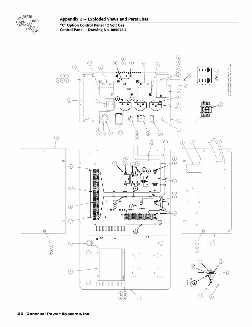
Appendix 2 — Exploded Views and Parts Lists“C” Option Control Panel 12 Volt GasControl Panel – Drawing No. 085026-J
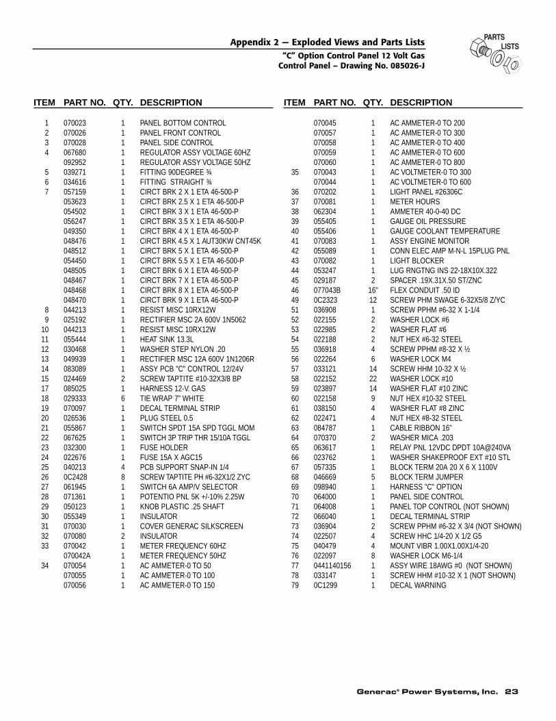
Generac® Power Systems, Inc. 23
ITEM PART NO. QTY. DESCRIPTION
1 070023 1 PANEL BOTTOM CONTROL2 070026 1 PANEL FRONT CONTROL3 070028 1 PANEL SIDE CONTROL4 067680 1 REGULATOR ASSY VOLTAGE 60HZ
092952 1 REGULATOR ASSY VOLTAGE 50HZ5 039271 1 FITTING 90DEGREE ¾6 034616 1 FITTING STRAIGHT ¾7 057159 1 CIRCT BRK 2 X 1 ETA 46-500-P
053623 1 CIRCT BRK 2.5 X 1 ETA 46-500-P054502 1 CIRCT BRK 3 X 1 ETA 46-500-P056247 1 CIRCT BRK 3.5 X 1 ETA 46-500-P049350 1 CIRCT BRK 4 X 1 ETA 46-500-P048476 1 CIRCT BRK 4.5 X 1 AUT30KW CNT45K048512 1 CIRCT BRK 5 X 1 ETA 46-500-P054450 1 CIRCT BRK 5.5 X 1 ETA 46-500-P048505 1 CIRCT BRK 6 X 1 ETA 46-500-P048467 1 CIRCT BRK 7 X 1 ETA 46-500-P048468 1 CIRCT BRK 8 X 1 ETA 46-500-P048470 1 CIRCT BRK 9 X 1 ETA 46-500-P
8 044213 1 RESIST MISC 10RX12W9 025192 1 RECTIFIER MSC 2A 600V 1N5062
10 044213 1 RESIST MISC 10RX12W11 055444 1 HEAT SINK 13.3L12 030468 1 WASHER STEP NYLON .2013 049939 1 RECTIFIER MSC 12A 600V 1N1206R14 083089 1 ASSY PCB "C" CONTROL 12/24V15 024469 2 SCREW TAPTITE #10-32X3/8 BP17 085025 1 HARNESS 12-V. GAS 18 029333 6 TIE WRAP 7" WHITE19 070097 1 DECAL TERMINAL STRIP20 026536 1 PLUG STEEL 0.521 055867 1 SWITCH SPDT 15A SPD TGGL MOM22 067625 1 SWITCH 3P TRIP THR 15/10A TGGL23 032300 1 FUSE HOLDER24 022676 1 FUSE 15A X AGC1525 040213 4 PCB SUPPORT SNAP-IN 1/426 0C2428 8 SCREW TAPTITE PH #6-32X1/2 ZYC27 061945 1 SWITCH 6A AMP/V SELECTOR28 071361 1 POTENTIO PNL 5K +/-10% 2.25W29 050123 1 KNOB PLASTIC .25 SHAFT30 055349 1 INSULATOR31 070030 1 COVER GENERAC SILKSCREEN32 070080 2 INSULATOR33 070042 1 METER FREQUENCY 60HZ
070042A 1 METER FREQUENCY 50HZ34 070054 1 AC AMMETER-0 TO 50
070055 1 AC AMMETER-0 TO 100070056 1 AC AMMETER-0 TO 150
ITEM PART NO. QTY. DESCRIPTION
070045 1 AC AMMETER-0 TO 200070057 1 AC AMMETER-0 TO 300070058 1 AC AMMETER-0 TO 400070059 1 AC AMMETER-0 TO 600070060 1 AC AMMETER-0 TO 800
35 070043 1 AC VOLTMETER-0 TO 300070044 1 AC VOLTMETER-0 TO 600
36 070202 1 LIGHT PANEL #26306C37 070081 1 METER HOURS38 062304 1 AMMETER 40-0-40 DC39 055405 1 GAUGE OIL PRESSURE40 055406 1 GAUGE COOLANT TEMPERATURE41 070083 1 ASSY ENGINE MONITOR42 055089 1 CONN ELEC AMP M-N-L 15PLUG PNL43 070082 1 LIGHT BLOCKER44 053247 1 LUG RNGTNG INS 22-18X10X.32245 029187 2 SPACER .19X.31X.50 ST/ZNC46 077043B 16" FLEX CONDUIT .50 ID49 0C2323 12 SCREW PHM SWAGE 6-32X5/8 Z/YC51 036908 1 SCREW PPHM #6-32 X 1-1/452 022155 2 WASHER LOCK #653 022985 2 WASHER FLAT #654 022188 2 NUT HEX #6-32 STEEL55 036918 4 SCREW PPHM #8-32 X ½56 022264 6 WASHER LOCK M457 033121 14 SCREW HHM 10-32 X ½58 022152 22 WASHER LOCK #1059 023897 14 WASHER FLAT #10 ZINC60 022158 9 NUT HEX #10-32 STEEL61 038150 4 WASHER FLAT #8 ZINC62 022471 4 NUT HEX #8-32 STEEL63 084787 1 CABLE RIBBON 16"64 070370 2 WASHER MICA .20365 063617 1 RELAY PNL 12VDC DPDT 10A@240VA66 023762 1 WASHER SHAKEPROOF EXT #10 STL67 057335 1 BLOCK TERM 20A 20 X 6 X 1100V68 046669 5 BLOCK TERM JUMPER 69 098940 1 HARNESS "C" OPTION70 064000 1 PANEL SIDE CONTROL71 064008 1 PANEL TOP CONTROL (NOT SHOWN)72 066040 1 DECAL TERMINAL STRIP73 036904 2 SCREW PPHM #6-32 X 3/4 (NOT SHOWN)74 022507 4 SCREW HHC 1/4-20 X 1/2 G575 040479 4 MOUNT VIBR 1.00X1.00X1/4-2076 022097 8 WASHER LOCK M6-1/477 0441140156 1 ASSY WIRE 18AWG #0 (NOT SHOWN)78 033147 1 SCREW HHM #10-32 X 1 (NOT SHOWN)79 0C1299 1 DECAL WARNING
Appendix 2 — Exploded Views and Parts Lists“C” Option Control Panel 12 Volt Gas
Control Panel – Drawing No. 085026-J
24 Generac® Power Systems, Inc.
TB
3G
EN
ER
AT
OR
CO
NT
RO
L P
AN
EL
00N
EU
TR
AL
1
1514
CU
ST
OM
ER
LOA
D
GT
S T
RA
NS
FE
R S
WIT
CH
NO
TE
5
GE
NE
RA
TO
R A
C C
ON
NE
CT
ION
PA
NE
L W
/2-W
IRE
ST
AR
T
1 4 7 AB963
211
209
15A
229
AU
XIL
IAR
YC
ON
TA
CT
S-N
OT
E 3
NO
TE
1
501
506
500
504
505
0
211
15
15
15
5 LI
GH
T -
RE
MO
TE
AN
NU
NC
IAT
OR
501
506
502
504
505
15
1514
506
501
500
15
9750
114
505
18317
8
NO
TE
4#702
87
EN
GIN
E M
ON
ITO
RC
IRC
UIT
BO
AR
D
HI-
LO B
AT
TE
RY
ALA
RM
960
15
0
0
15
15
98
506
505
500502
504
506500
502
505
94
96
9798
137
15
15
1550
2
14
228
519
525
519
525
525
NO
TE
S:
1. 3
-PO
LE, 1
-PH
AS
E &
4-P
OLE
, 3-P
HA
SE
TR
AN
SF
ER
SW
ITC
HE
S G
EN
ER
ALL
Y N
OT
EQ
UIP
PE
D W
ITH
NE
UT
RA
L B
LOC
K2.
2 A
MP
CH
AR
GE
R W
ITH
12
VO
LTS
SIN
GLE
BA
TT
ER
Y S
YS
TE
M
SH
OW
N.
FO
R O
TH
ER
VA
RIA
TIO
N S
EE
INS
ET
"A
"3.
SE
E IN
SE
TS
"D
" &
"E
"
PR
EA
LAR
M L
IGH
TS
ON
GE
NE
RA
TO
R C
ON
TR
OL
PA
NE
L. O
N U
NIT
S W
ITH
OU
T T
B3
CO
NN
EC
T W
IRE
S 5
00 T
HR
U 5
06 D
IRE
CT
LY T
O R
EM
OT
E A
NN
UN
CIA
TO
R5.
MO
DE
L 82
35 A
LAR
M H
OR
N S
HO
WN
FO
R "
C"-
OP
TIO
N U
NIT
S.
TB
2 T
ER
MIN
ALS
209
-210
-211
CO
NN
EC
T T
P A
LAR
M R
ELA
Y
209
NC
CO
NT
AC
TS
OP
EN
ON
AN
NU
NC
IAT
ED
SH
UT
DO
WN
211
NO
CO
NT
AC
TS
CLO
SE
ON
AN
NU
NC
IAT
ED
SH
UT
DO
WN
210
C
CO
NN
EC
T T
O F
US
E +
12V
DC
CIR
CU
IT A
S S
HO
WN
118
1920
21
C.
LOW
CO
OLA
NT
TE
MP
. SW
ITC
H
PR
EA
LAR
MLO
W O
IL P
RE
SS
.
PR
EA
LAR
M H
IGH
CO
OLA
NT
TE
MP
.
LOW
FU
EL
LEV
EL
SW
ITC
H
EN
GIN
E
FU
EL
TA
NK
N2
N1
T1
T2
E2
E3
E1
UT
ILIT
YS
UP
PLY
E1
E3
E2
24
CO
NT
AC
TS
. FO
R "
A"
& "
B"
OP
TIO
N U
NIT
S, S
EE
INS
ET
"G
".
SW
ITC
HM
AN
UA
L/A
UT
O/O
FF
32
1
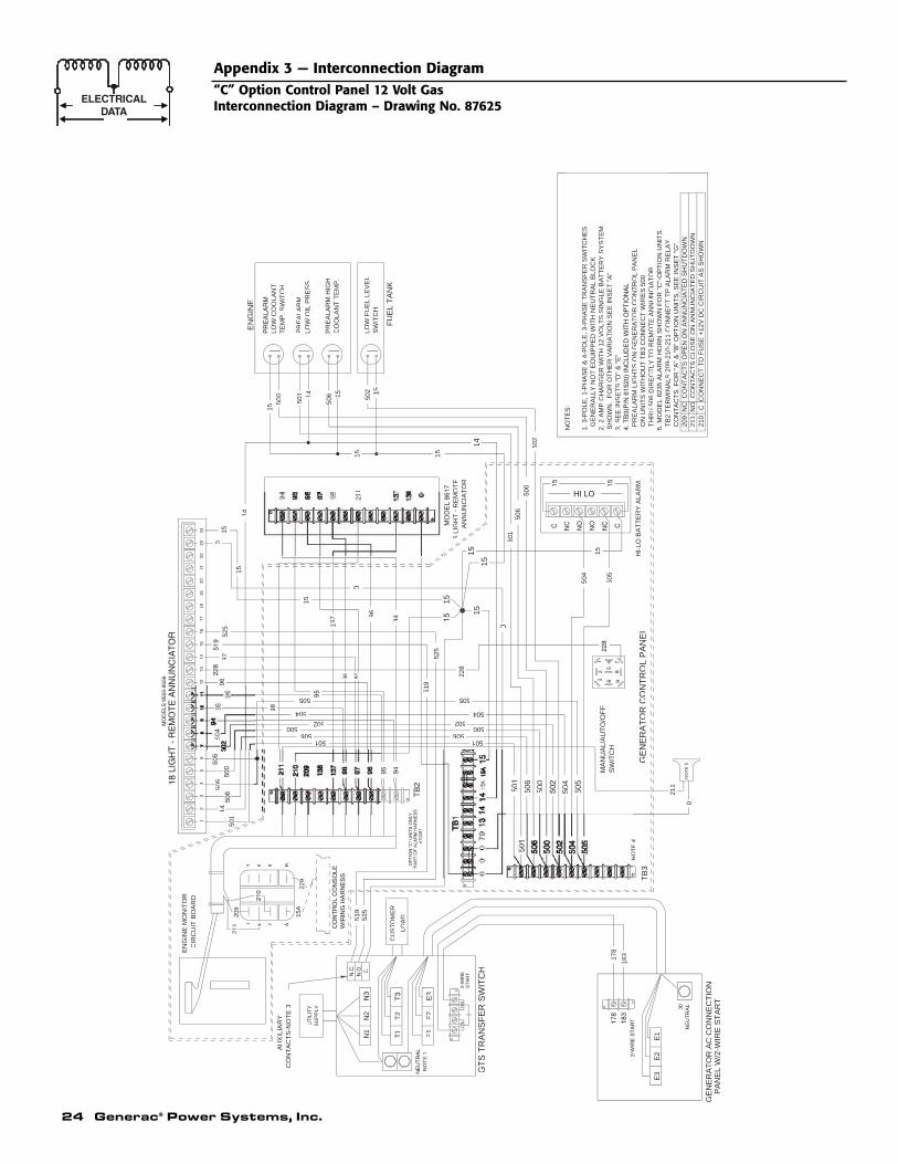
Appendix 3 — Interconnection Diagram“C” Option Control Panel 12 Volt GasInterconnection Diagram – Drawing No. 87625
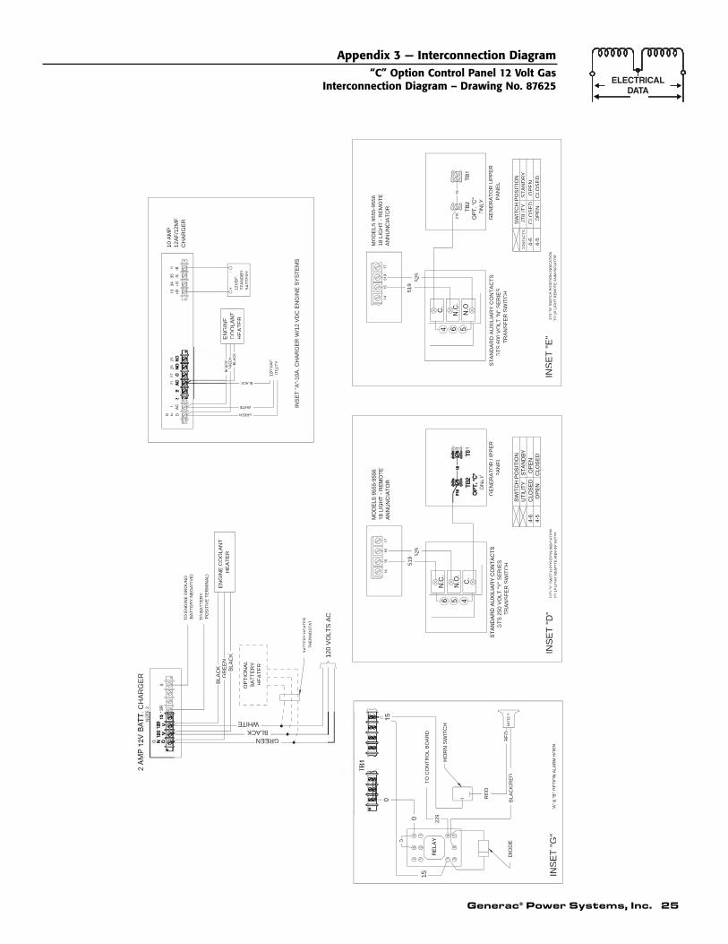
Generac® Power Systems, Inc. 25
Appendix 3 — Interconnection Diagram“C” Option Control Panel 12 Volt Gas
Interconnection Diagram – Drawing No. 87625
EN
GIN
E C
OO
LAN
TH
EA
TE
R
OP
TIO
NA
LB
AT
TE
RY
HE
AT
ER
BLA
CK BLA
CK
GR
EE
N
120
VO
LTS
AC
GREENBLACK
WHITE
2 A
MP
12V
BA
TT
. CH
AR
GE
RE
2
G N1
2127
2829
0
BA
TT
ER
YH
EA
TE
RT
HE
RM
OS
TA
T
GREEN
WHITE
BLACK
GT
S 2
50 V
OLT
"Y
" S
ER
IES
TR
AN
SF
ER
SW
ITC
H
INS
ET
"D
"IN
SE
T "
E"
TR
AN
SF
ER
SW
ITC
HG
TS
600
VO
LT "
N"
SE
RIE
SS
TA
ND
AR
D A
UX
ILIA
RY
CO
NT
AC
TS
4-6
4-5
UT
ILIT
Y
ST
AN
DB
YC
LOS
ED
O
PE
NO
PE
N
CLO
SE
D
SW
ITC
H P
OS
ITIO
NC
ON
TA
CT
S
GT
S "
Y"
SW
ITC
H P
OS
ITIO
N IN
DIC
AT
ION
TO
18
LIG
HT
RE
MO
TE
AN
NU
NC
IAT
OR
ON
LY
GE
NE
RA
TO
R U
PP
ER
PA
NE
L
ON
LY
GE
NE
RA
TO
R U
PP
ER
PA
NE
L
MO
DE
LS 9
555-
9556
18 L
IGH
T -
RE
MO
TE
AN
NU
NC
IAT
OR
GT
S "
N"
SW
ITC
H P
OS
ITIO
N IN
DIC
AT
ION
TO
18
LIG
HT
RE
MO
TE
AN
NU
NC
IAT
OR
TO
EN
GIN
E G
RO
UN
D(B
AT
TE
RY
NE
GA
TIV
E)
TO
BA
TT
ER
Y(P
OS
ITIV
E T
ER
MIN
AL)
BLA
CK
/RE
DR
ED
"A"
& "
B"
OP
TIO
N A
LAR
M H
OR
NIN
SE
T "
G"
HO
RN
SW
ITC
H
DIO
DE
15
0
0
BA
98
7
6 3
NO
TE
5
RE
D
GR
EE
NB
LAC
K
BLA
CK
519 52
552
551
9
TO
CO
NT
RO
L B
OA
RD
229
EN
GIN
EC
OO
LAN
TH
EA
TE
R
10 A
MP
12A
F/1
2MF
CH
AR
GE
R
12V
DC
ST
AN
DB
YB
AT
TE
RY
+-
120
VA
CU
TIL
ITY
INS
ET
"A
"-10
A. C
HA
RG
ER
W/1
2 V
DC
EN
GIN
E S
YS
TE
MS
26 Generac® Power Systems, Inc.
TB
2
TB
3G
EN
ER
AT
OR
CO
NT
RO
L P
AN
EL
00N
EU
TR
AL
220
219
CU
ST
OM
ER
LOA
D
GT
S T
RA
NS
FE
R S
WIT
CH
NO
TE
5
GE
NE
RA
TO
R A
C C
ON
NE
CT
ION
PA
NE
L W
/2-W
IRE
ST
AR
T
B963
211
209
220A
229
AU
XIL
IAR
YC
ON
TA
CT
S-N
OT
E 3
NE
UT
RA
LN
OT
E 1
501
500
504
0
211
220
220
220
5 LI
GH
T -
RE
MO
TE
AN
NU
NC
IAT
OR
501
506
502
504
505
220
220
219
506
501
500
220
9750
1
219
505
18317
8
NO
TE
4#847
16
EN
GIN
E M
ON
ITO
RC
IRC
UIT
BO
AR
D
HI-
LO B
AT
TE
RY
ALA
RM
960
220
0
0
220
220
98
506
505
500
504
505
94
96
9798
137
220
220
220
502
219
228
RE
SIS
TO
R
519
525
519
519
525
525
C.
LOW
CO
OLA
NT
TE
MP
. SW
ITC
H
PR
EA
LAR
MLO
W O
IL P
RE
SS
.
PR
EA
LAR
M H
IGH
CO
OLA
NT
TE
MP
.
LOW
FU
EL
LEV
EL
SW
ITC
H
EN
GIN
E
FU
EL
TA
NK
N2
N3
N1
T1
T2
E2
E3
E1
UT
ILIT
YS
UP
PLY
E1
E3
E2
220
220
C NC
NO
NO
NC C
PR
EA
LAR
M
NO
TE
S:
1. 3
-PO
LE, 1
-PH
AS
E &
4-P
OLE
, 3-P
HA
SE
TR
AN
SF
ER
SW
ITC
HE
S G
EN
ER
ALL
Y N
OT
EQ
UIP
PE
D W
ITH
NE
UT
RA
L B
LOC
K2.
4.0
L &
6.4
L U
NIT
S R
EQ
UIR
E 1
20 V
AC
FO
R E
NG
INE
CO
OLA
NT
"B
" &
"C
"3.
SE
E IN
SE
TS
"D
" &
"E
"
PR
EA
LAR
M L
IGH
TS
ON
GE
NE
RA
TO
R C
ON
TR
OL
PA
NE
L. O
N U
NIT
S W
ITH
OU
T T
B3
CO
NN
EC
T W
IRE
S 5
00 T
HR
U 5
06 D
IRE
CT
LY T
O R
EM
OT
E A
NN
UN
CIA
TO
R5.
MO
DE
L 82
35 A
LAR
M H
OR
N S
HO
WN
FO
R "
C"-
OP
TIO
N U
NIT
S.
TB
2 T
ER
MIN
AL S
209
-210
-211
CO
NN
EC
T T
O A
LAR
M R
ELA
Y
209
NC
CO
NT
AC
TS
OP
EN
ON
AN
NU
NC
IAT
ED
SH
UT
DO
WN
211
NO
CO
NT
AC
TS
CLO
SE
ON
AN
NU
NC
IAT
ED
SH
UT
DO
WN
210
C
CO
NN
EC
T T
O F
US
E +
24V
DC
CIR
CU
IT A
S S
HO
WN
CO
NT
AC
TS
. FO
R "
A"
& "
B"
OP
TIO
N U
NIT
S, S
EE
INS
ET
"G
".
SW
ITC
HM
AN
UA
L/A
UT
O/O
FF
32
1
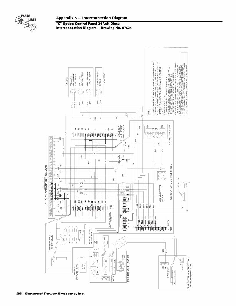
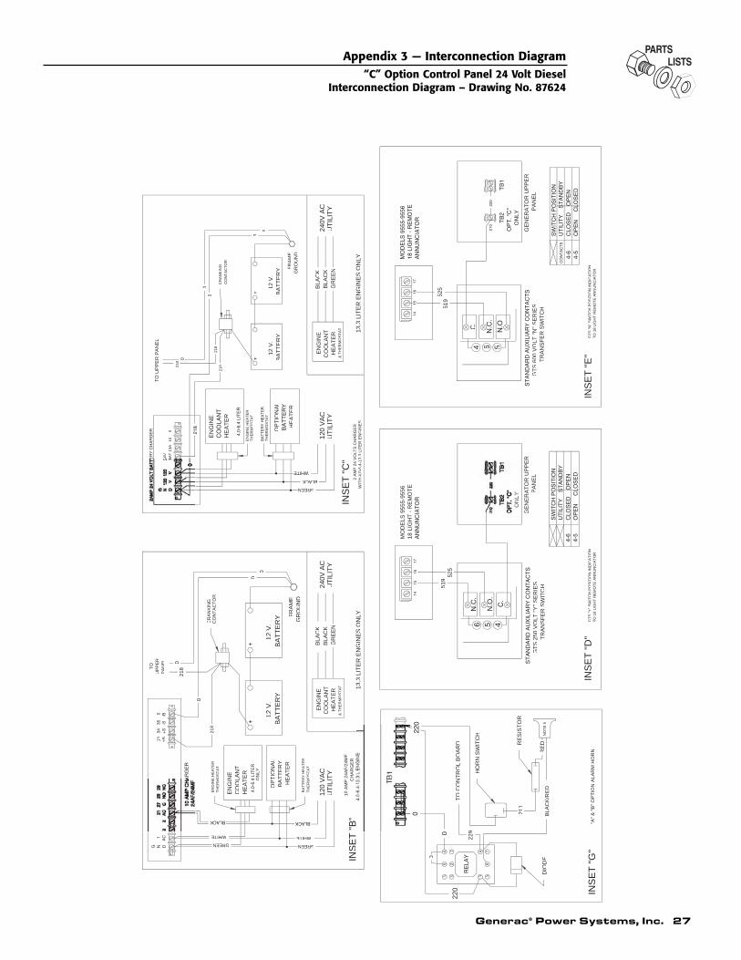
Appendix 3 — Interconnection Diagram“C” Option Control Panel 24 Volt DieselInterconnection Diagram – Drawing No. 87624
Generac® Power Systems, Inc. 27
Appendix 3 — Interconnection Diagram“C” Option Control Panel 24 Volt Diesel
Interconnection Diagram – Drawing No. 87624
EN
GIN
EC
OO
LAN
TH
EA
TE
R
12V
.B
AT
TE
RY
120
VA
CU
TIL
ITY
EN
GIN
EC
OO
LAN
T
OP
TIO
NA
LB
AT
TE
RY
HE
AT
ER
13 +B
INS
ET
"B
"4
06
413
3L
EN
GIN
E
10 A
MP
24A
F/2
4MF
CH
AR
GE
R
HE
AT
ER 13
.3 L
ITE
R E
NG
INE
S O
NLY
UT
ILIT
Y24
0V A
CB
LAC
KB
LAC
KG
RE
EN
4.0-
6.4
LIT
ER
ON
LY
BA
TT
ER
Y12
V.
FR
AM
EG
RO
UN
D
TO
UP
PE
RP
AN
EL
218
GREEN
WHITE
218
0
GREEN
WHITE
BA
TT
ER
YH
EA
TE
RT
HE
RM
OS
TA
T
EN
GIN
E H
EA
TE
RT
HE
RM
OS
TA
T
CR
AN
KIN
GC
ON
TA
CT
OR
& T
HE
RM
OS
TA
T
0
0
0
+-
-+
BLACK
GREEN
GR
OU
ND
FR
AM
E
12V
.B
AT
TE
RY
GR
EE
NB
LAC
KB
LAC
K24
0V A
CU
TIL
ITY
13.3
LIT
ER
EN
GIN
ES
ON
LY
HE
AT
ER
2 A
MP
24
VO
LTS
CH
AR
GE
R
INS
ET
"C
"
010
13A
BA
T
HE
AT
ER
OP
TIO
NA
L
CO
OLA
NT
EN
GIN
E
UT
ILIT
Y12
0 V
AC
BA
TT
ER
Y12
V.
HE
AT
ER
EN
GIN
E
WIT
H 4
.0-6
.4-1
3.3
LIT
ER
EN
GIN
ES
TO
UP
PE
R P
AN
EL
24V
CR
AN
KIN
GC
ON
TA
CT
OR
218
218
& T
HE
RM
OS
TA
T
TH
ER
MO
ST
AT
EN
GIN
E H
EA
TE
RT
HE
RM
OS
TA
T
0
0
0
0
0
218
+-
-+
GT
S 2
50 V
OLT
"Y
" S
ER
IES
TR
AN
SF
ER
SW
ITC
H
INS
ET
"D
"
MO
DE
LS 9
555-
9556
18 L
IGH
T -
RE
MO
TE
GT
S "
Y"
SW
ITC
H P
OS
ITIO
N IN
DIC
AT
ION
TO
18
LIG
HT
RE
MO
TE
AN
NU
NC
IAT
OR
ON
LY
GE
NE
RA
TO
R U
PP
ER
PA
NE
L
519
525
4 6 5
INS
ET
"E
"
TR
AN
SF
ER
SW
ITC
HG
TS
600
VO
LT "
N"
SE
RIE
S
ON
LY
GE
NE
RA
TO
R U
PP
ER
PA
NE
L
GT
S "
N"
SW
ITC
H P
OS
ITIO
N IN
DIC
AT
ION
TO
18
LIG
HT
RE
MO
TE
AN
NU
NC
IAT
OR
519
525
C.
RE
SIS
TO
R21
1
NO
TE
5
36
78
9
AB
0
0
220
DIO
DE
HO
RN
SW
ITC
H
INS
ET
"G
""A
" &
"B
" O
PT
ION
ALA
RM
HO
RNR
ED
BLA
CK
/RE
D
TO
CO
NT
RO
L B
OA
RD
229

28 Generac® Power Systems, Inc.
Part II
Remote AnnunciatorPanels
Generac® Power Systems, Inc. 29
Section 1 — General InformationRemote Annunciator Panels
1.1 THREE LIGHT REMOTE ANNUNCIATOR
The Generac Three Light Remote Annunciator(Figure 1.1) provides a valuable reference when usedwith the Generac automatic transfer switch andstandby generator with a C option control panel.
This equipment is designed to be mounted remotelyfrom the standby generator set. The panel, whenproperly interconnected with a Generac standby gen-erator system and transfer switch, annunciates up tothree (3) standby electric system operating parame-ters.
• Utility Power Supply: This light comes ON whencustomer electric loads are being powered by theNORMAL (utility) power source.
• Emergency Power Supply: This light comes ONwhen customer electric loads are being powered bythe EMERGENCY (standby) power source.
• Generator Fault Light: This light comes ON whenthe generator engine has shut down automaticallydue to a fault condition (such as low oil pressure,high coolant temperature, overcrank, overspeed,or RPM sensor loss). Fault conditions that willresult in an automatic engine shutdown are dis-cussed in the INSTRUCTIONS AND PARTS MANU-AL for the applicable generator set.
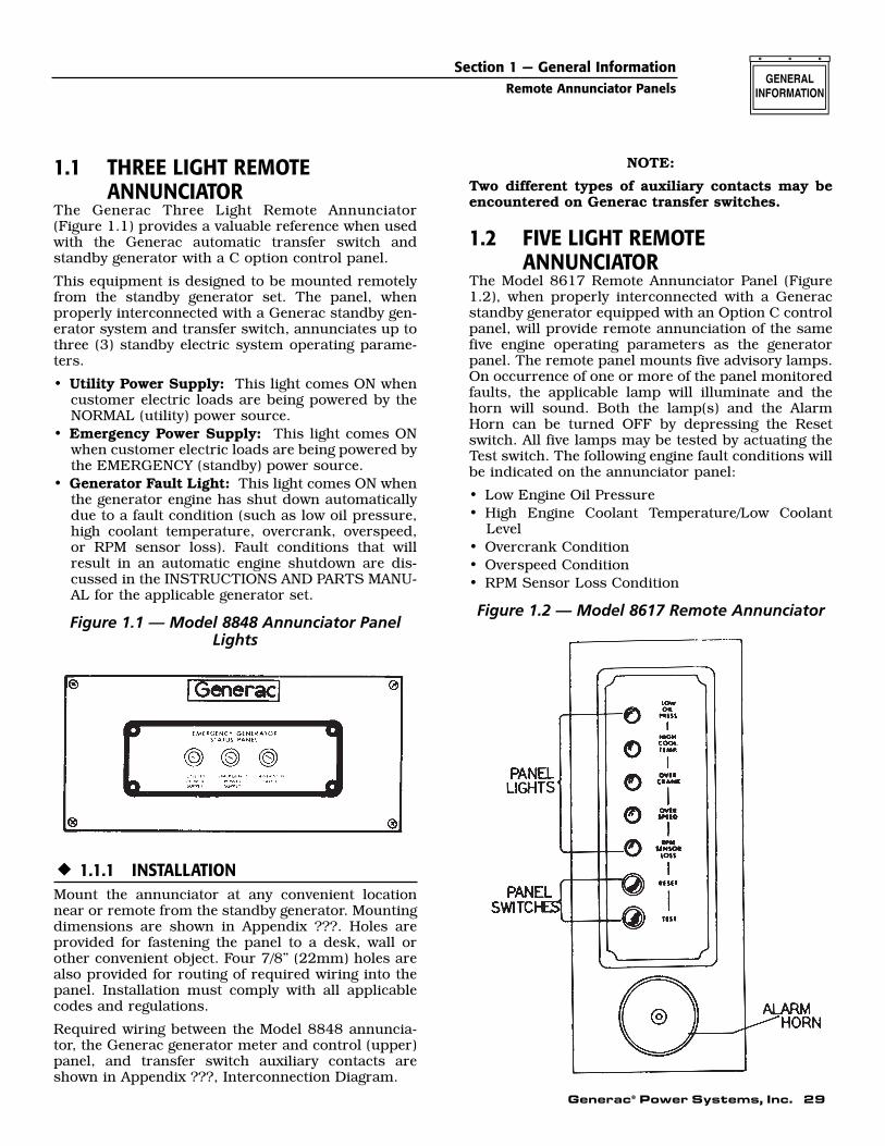
Figure 1.1 — Model 8848 Annunciator PanelLights
1.1.1 INSTALLATIONMount the annunciator at any convenient locationnear or remote from the standby generator. Mountingdimensions are shown in Appendix ???. Holes areprovided for fastening the panel to a desk, wall orother convenient object. Four 7/8” (22mm) holes arealso provided for routing of required wiring into thepanel. Installation must comply with all applicablecodes and regulations.
Required wiring between the Model 8848 annuncia-tor, the Generac generator meter and control (upper)panel, and transfer switch auxiliary contacts areshown in Appendix ???, Interconnection Diagram.
NOTE:
Two different types of auxiliary contacts may beencountered on Generac transfer switches.
1.2 FIVE LIGHT REMOTE ANNUNCIATOR
The Model 8617 Remote Annunciator Panel (Figure1.2), when properly interconnected with a Generacstandby generator equipped with an Option C controlpanel, will provide remote annunciation of the samefive engine operating parameters as the generatorpanel. The remote panel mounts five advisory lamps.On occurrence of one or more of the panel monitoredfaults, the applicable lamp will illuminate and thehorn will sound. Both the lamp(s) and the AlarmHorn can be turned OFF by depressing the Resetswitch. All five lamps may be tested by actuating theTest switch. The following engine fault conditions willbe indicated on the annunciator panel:
• Low Engine Oil Pressure• High Engine Coolant Temperature/Low Coolant
Level• Overcrank Condition• Overspeed Condition• RPM Sensor Loss Condition
Figure 1.2 — Model 8617 Remote Annunciator
30 Generac® Power Systems, Inc.
Section 1 — General InformationRemote Annunciator Panels
1.2.1 OPERATIONBoth the remote and generator panel advisory lampsare controlled by a single DC CONTROL-LATCH-CRANK circuit board housed in the generator controlconsole. Engine mounted, normally open (N.O.)switches and sensors provide the necessary signal tothe circuit board on occurrence of a monitoredengine fault. should any one (or more) of the moni-tored faults occur, an automatic engine shutdown,illumination of the applicable lamp(s), and soundingof the Alarm Horn will occur. circuit board action willthen “latch” the fault. That is, the applicable lamp(s)will remain ON after engine shutdown. While anylamp remains lighted (latched), further attempts atgenerator cranking and startup are inhibited. A 12volt DC input is required to operate the panel.
NOTE:
See applicable standby generator owner’s manualfor more detailed operational description ofremote and generator panel lamps.
1.2.2 CUSTOMER CONNECTIONSSuitable, approved wiring must be purchased forinterconnection of the Remote Annunciator Panelwith Terminal block TB2. Connect each wire to anumbered terminal block screw and to an identicallynumbered terminal in the remote annunciator panel.A total of nine wires are required. Numbered termi-nals may be identified as follows:
• #94 — Low Oil Pressure Shutdown• #95 — High Coolant Temperature/Low Coolant
Level Shutdown• #96 — Overcrank Shutdown• #97 — Overspeed Shutdown• #98 — RPM Sensor Loss Shutdown• #137 — Test Switch Connections• #138 — Reset Switch Connections• #209 — Alarm Relay Normally Closed Contacts*• #210 — Alarm Relay Common Contacts*• #211 — Alarm Relay Normally Open Contacts** DO NOT EXCEED ONE (1) AMPERE OF CURRENT
ACROSS ALARM RELAY CONTACTS.
1.2.3 PARTS INCLUDED WITH REMOTEPANEL
Factory shipment of any standby generator set whichincludes the optional Remote Annunciator Panel willinclude a WIRING HARNESS (Part No. 70287). TheWIRING HARNESS includes the following parts:
1. Terminal Block TB2 (Part No. 55911)2. Terminal Block Decal (Part No. 66040)3. Alarm Relay (Part No. 63617)4. The Wiring Harness proper
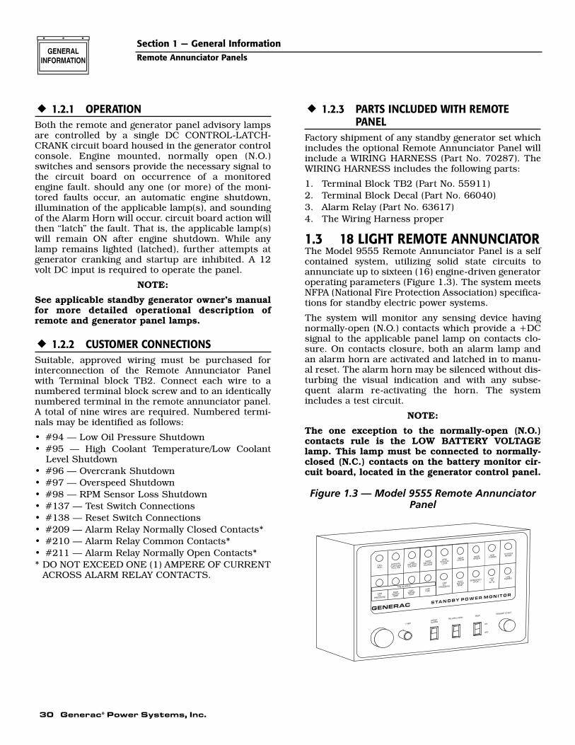
1.3 18 LIGHT REMOTE ANNUNCIATORThe Model 9555 Remote Annunciator Panel is a selfcontained system, utilizing solid state circuits toannunciate up to sixteen (16) engine-driven generatoroperating parameters (Figure 1.3). The system meetsNFPA (National Fire Protection Association) specifica-tions for standby electric power systems.
The system will monitor any sensing device havingnormally-open (N.O.) contacts which provide a +DCsignal to the applicable panel lamp on contacts clo-sure. On contacts closure, both an alarm lamp andan alarm horn are activated and latched in to manu-al reset. The alarm horn may be silenced without dis-turbing the visual indication and with any subse-quent alarm re-activating the horn. The systemincludes a test circuit.
NOTE:
The one exception to the normally-open (N.O.)contacts rule is the LOW BATTERY VOLTAGElamp. This lamp must be connected to normally-closed (N.C.) contacts on the battery monitor cir-cuit board, located in the generator control panel.
Figure 1.3 — Model 9555 Remote AnnunciatorPanel
Generac® Power Systems, Inc. 31
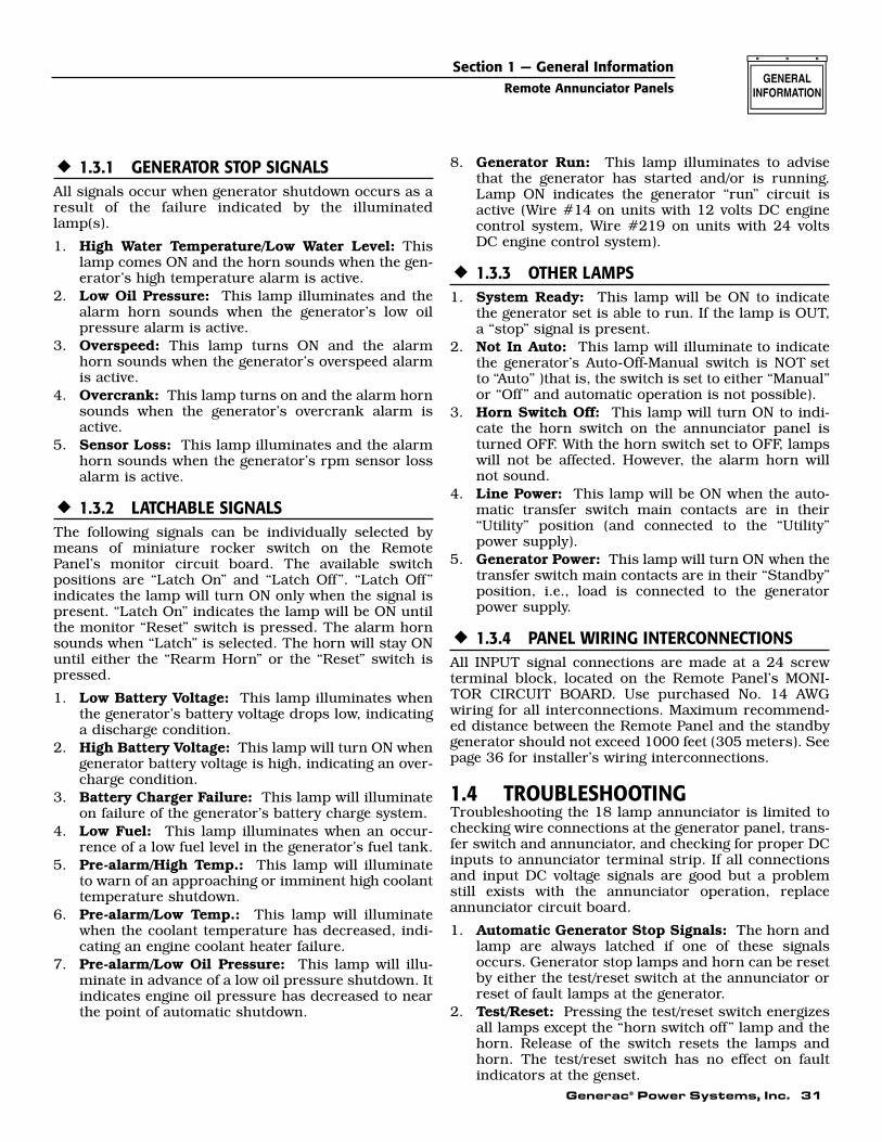
1.3.1 GENERATOR STOP SIGNALSAll signals occur when generator shutdown occurs as aresult of the failure indicated by the illuminatedlamp(s).
1. High Water Temperature/Low Water Level: Thislamp comes ON and the horn sounds when the gen-erator’s high temperature alarm is active.
2. Low Oil Pressure: This lamp illuminates and thealarm horn sounds when the generator’s low oilpressure alarm is active.
3. Overspeed: This lamp turns ON and the alarmhorn sounds when the generator’s overspeed alarmis active.
4. Overcrank: This lamp turns on and the alarm hornsounds when the generator’s overcrank alarm isactive.
5. Sensor Loss: This lamp illuminates and the alarmhorn sounds when the generator’s rpm sensor lossalarm is active.
1.3.2 LATCHABLE SIGNALSThe following signals can be individually selected bymeans of miniature rocker switch on the RemotePanel’s monitor circuit board. The available switchpositions are “Latch On” and “Latch Off”. “Latch Off”indicates the lamp will turn ON only when the signal ispresent. “Latch On” indicates the lamp will be ON untilthe monitor “Reset” switch is pressed. The alarm hornsounds when “Latch” is selected. The horn will stay ONuntil either the “Rearm Horn” or the “Reset” switch ispressed.
1. Low Battery Voltage: This lamp illuminates whenthe generator’s battery voltage drops low, indicatinga discharge condition.
2. High Battery Voltage: This lamp will turn ON whengenerator battery voltage is high, indicating an over-charge condition.
3. Battery Charger Failure: This lamp will illuminateon failure of the generator’s battery charge system.
4. Low Fuel: This lamp illuminates when an occur-rence of a low fuel level in the generator’s fuel tank.
5. Pre-alarm/High Temp.: This lamp will illuminateto warn of an approaching or imminent high coolanttemperature shutdown.
6. Pre-alarm/Low Temp.: This lamp will illuminatewhen the coolant temperature has decreased, indi-cating an engine coolant heater failure.
7. Pre-alarm/Low Oil Pressure: This lamp will illu-minate in advance of a low oil pressure shutdown. Itindicates engine oil pressure has decreased to nearthe point of automatic shutdown.
8. Generator Run: This lamp illuminates to advisethat the generator has started and/or is running.Lamp ON indicates the generator “run” circuit isactive (Wire #14 on units with 12 volts DC enginecontrol system, Wire #219 on units with 24 voltsDC engine control system).
1.3.3 OTHER LAMPS1. System Ready: This lamp will be ON to indicate
the generator set is able to run. If the lamp is OUT,a “stop” signal is present.
2. Not In Auto: This lamp will illuminate to indicatethe generator’s Auto-Off-Manual switch is NOT setto “Auto” )that is, the switch is set to either “Manual”or “Off” and automatic operation is not possible).
3. Horn Switch Off: This lamp will turn ON to indi-cate the horn switch on the annunciator panel isturned OFF. With the horn switch set to OFF, lampswill not be affected. However, the alarm horn willnot sound.
4. Line Power: This lamp will be ON when the auto-matic transfer switch main contacts are in their“Utility” position (and connected to the “Utility”power supply).
5. Generator Power: This lamp will turn ON when thetransfer switch main contacts are in their “Standby”position, i.e., load is connected to the generatorpower supply.
1.3.4 PANEL WIRING INTERCONNECTIONSAll INPUT signal connections are made at a 24 screwterminal block, located on the Remote Panel’s MONI-TOR CIRCUIT BOARD. Use purchased No. 14 AWGwiring for all interconnections. Maximum recommend-ed distance between the Remote Panel and the standbygenerator should not exceed 1000 feet (305 meters). Seepage 36 for installer’s wiring interconnections.
1.4 TROUBLESHOOTINGTroubleshooting the 18 lamp annunciator is limited tochecking wire connections at the generator panel, trans-fer switch and annunciator, and checking for proper DCinputs to annunciator terminal strip. If all connectionsand input DC voltage signals are good but a problemstill exists with the annunciator operation, replaceannunciator circuit board.
1. Automatic Generator Stop Signals: The horn andlamp are always latched if one of these signalsoccurs. Generator stop lamps and horn can be resetby either the test/reset switch at the annunciator orreset of fault lamps at the generator.
2. Test/Reset: Pressing the test/reset switch energizesall lamps except the “horn switch off” lamp and thehorn. Release of the switch resets the lamps andhorn. The test/reset switch has no effect on faultindicators at the genset.
Section 1 — General InformationRemote Annunciator Panels
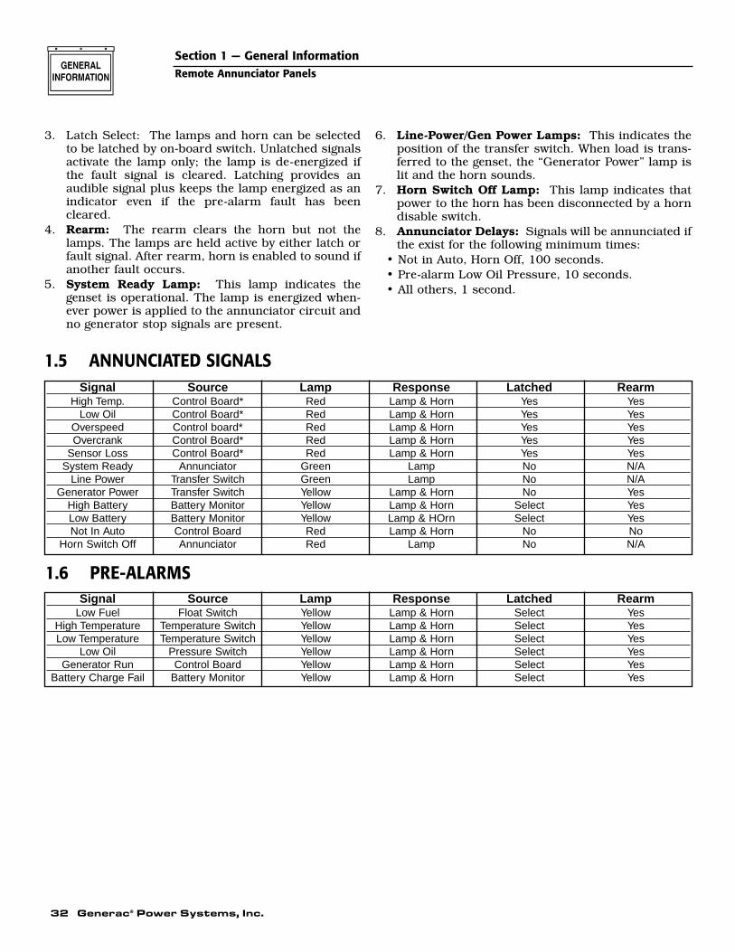
32 Generac® Power Systems, Inc.
Section 1 — General InformationRemote Annunciator Panels
3. Latch Select: The lamps and horn can be selectedto be latched by on-board switch. Unlatched signalsactivate the lamp only; the lamp is de-energized ifthe fault signal is cleared. Latching provides anaudible signal plus keeps the lamp energized as anindicator even if the pre-alarm fault has beencleared.
4. Rearm: The rearm clears the horn but not thelamps. The lamps are held active by either latch orfault signal. After rearm, horn is enabled to sound ifanother fault occurs.
5. System Ready Lamp: This lamp indicates thegenset is operational. The lamp is energized when-ever power is applied to the annunciator circuit andno generator stop signals are present.
6. Line-Power/Gen Power Lamps: This indicates theposition of the transfer switch. When load is trans-ferred to the genset, the “Generator Power” lamp islit and the horn sounds.
7. Horn Switch Off Lamp: This lamp indicates thatpower to the horn has been disconnected by a horndisable switch.
8. Annunciator Delays: Signals will be annunciated ifthe exist for the following minimum times:
• Not in Auto, Horn Off, 100 seconds.• Pre-alarm Low Oil Pressure, 10 seconds.• All others, 1 second.
Signal Source Lamp Response Latched RearmHigh Temp. Control Board* Red Lamp & Horn Yes Yes
Low Oil Control Board* Red Lamp & Horn Yes YesOverspeed Control board* Red Lamp & Horn Yes YesOvercrank Control Board* Red Lamp & Horn Yes Yes
Sensor Loss Control Board* Red Lamp & Horn Yes YesSystem Ready Annunciator Green Lamp No N/A
Line Power Transfer Switch Green Lamp No N/AGenerator Power Transfer Switch Yellow Lamp & Horn No Yes
High Battery Battery Monitor Yellow Lamp & Horn Select YesLow Battery Battery Monitor Yellow Lamp & HOrn Select YesNot In Auto Control Board Red Lamp & Horn No No
Horn Switch Off Annunciator Red Lamp No N/A
Signal Source Lamp Response Latched RearmLow Fuel Float Switch Yellow Lamp & Horn Select Yes
High Temperature Temperature Switch Yellow Lamp & Horn Select YesLow Temperature Temperature Switch Yellow Lamp & Horn Select Yes
Low Oil Pressure Switch Yellow Lamp & Horn Select YesGenerator Run Control Board Yellow Lamp & Horn Select Yes
Battery Charge Fail Battery Monitor Yellow Lamp & Horn Select Yes
1.5 ANNUNCIATED SIGNALS
1.6 PRE-ALARMS
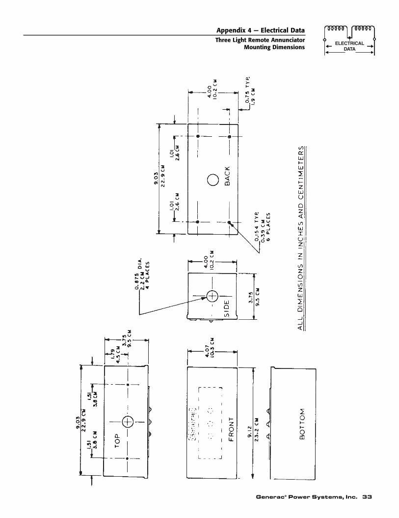
Generac® Power Systems, Inc. 33
Appendix 4 — Electrical DataThree Light Remote Annunciator
Mounting Dimensions
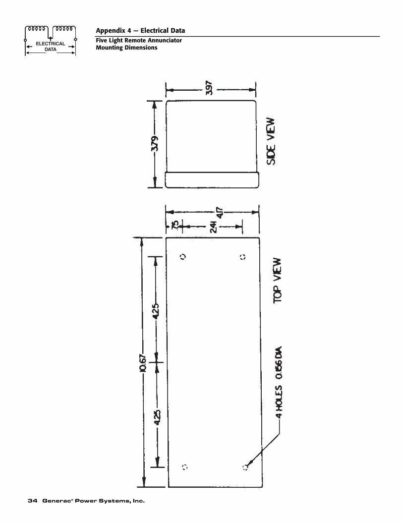
34 Generac® Power Systems, Inc.
Appendix 4 — Electrical DataFive Light Remote AnnunciatorMounting Dimensions
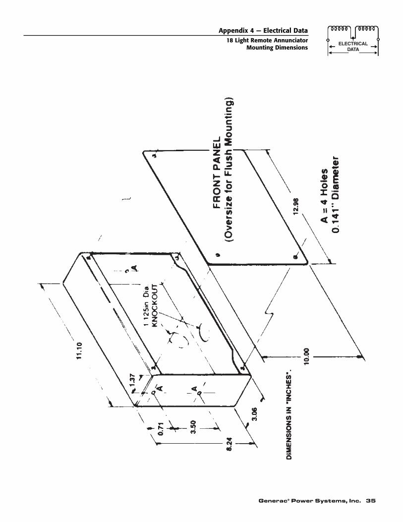
Generac® Power Systems, Inc. 35
Appendix 4 — Electrical Data18 Light Remote Annunciator
Mounting Dimensions
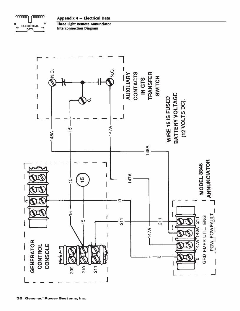
36 Generac® Power Systems, Inc.
Appendix 4 — Electrical DataThree Light Remote AnnunciatorInterconnection Diagram
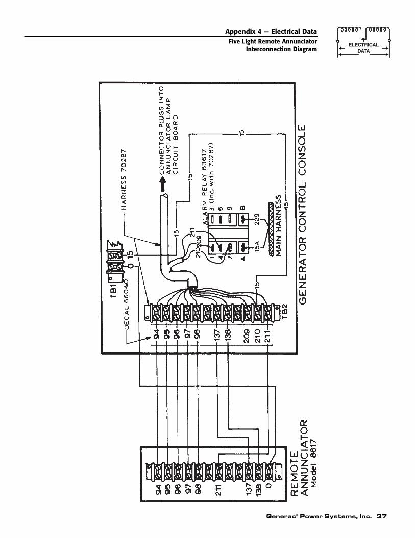
Generac® Power Systems, Inc. 37
Appendix 4 — Electrical DataFive Light Remote Annunciator
Interconnection Diagram
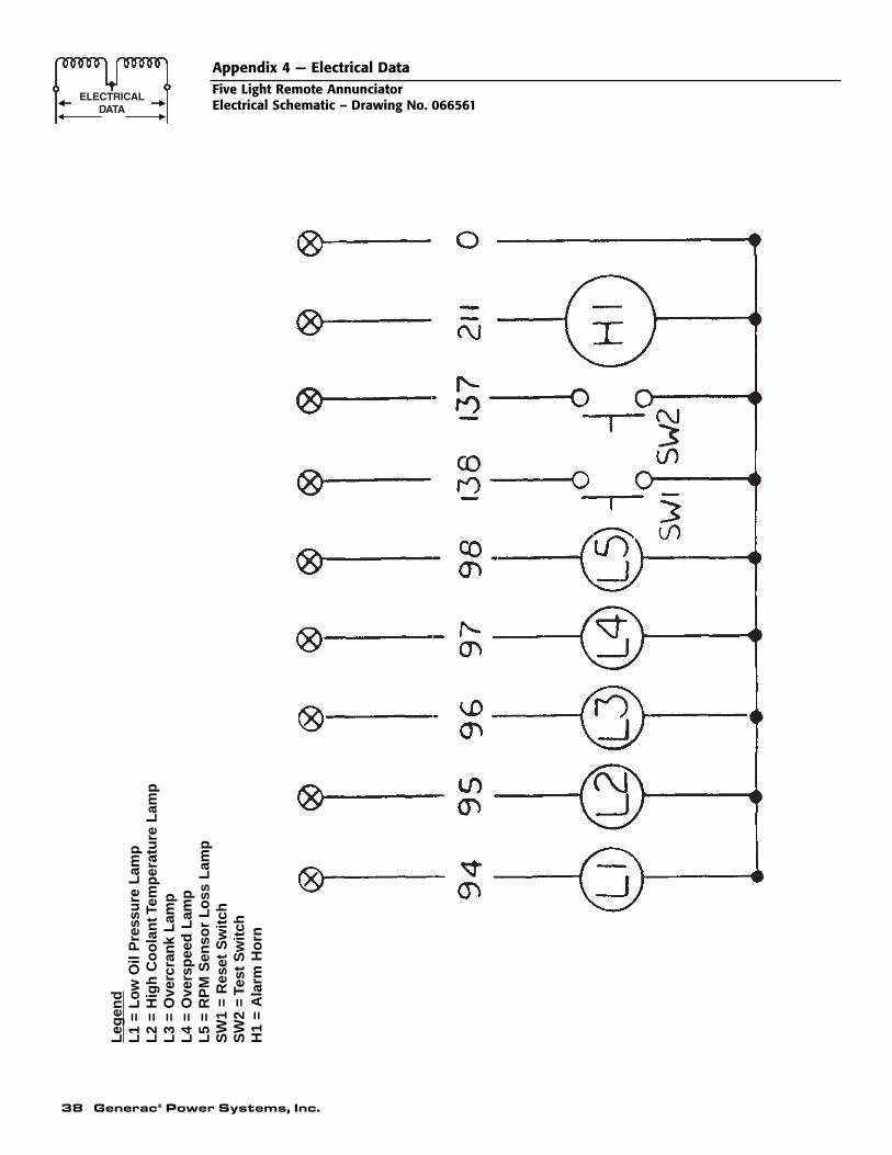
38 Generac® Power Systems, Inc.
Appendix 4 — Electrical DataFive Light Remote AnnunciatorElectrical Schematic – Drawing No. 066561
Leg
end
L1
= L
ow
Oil
Pre
ssu
re L
amp
L2
= H
igh
Co
ola
nt T
emp
erat
ure
Lam
pL
3 =
Ove
rcra
nk
Lam
pL
4 =
Ove
rsp
eed
Lam
pL
5 =
RP
M S
enso
r L
oss
Lam
pS
W1
= R
eset
Sw
itch
SW
2 =
Test
Sw
itch
H1
= A
larm
Ho
rn
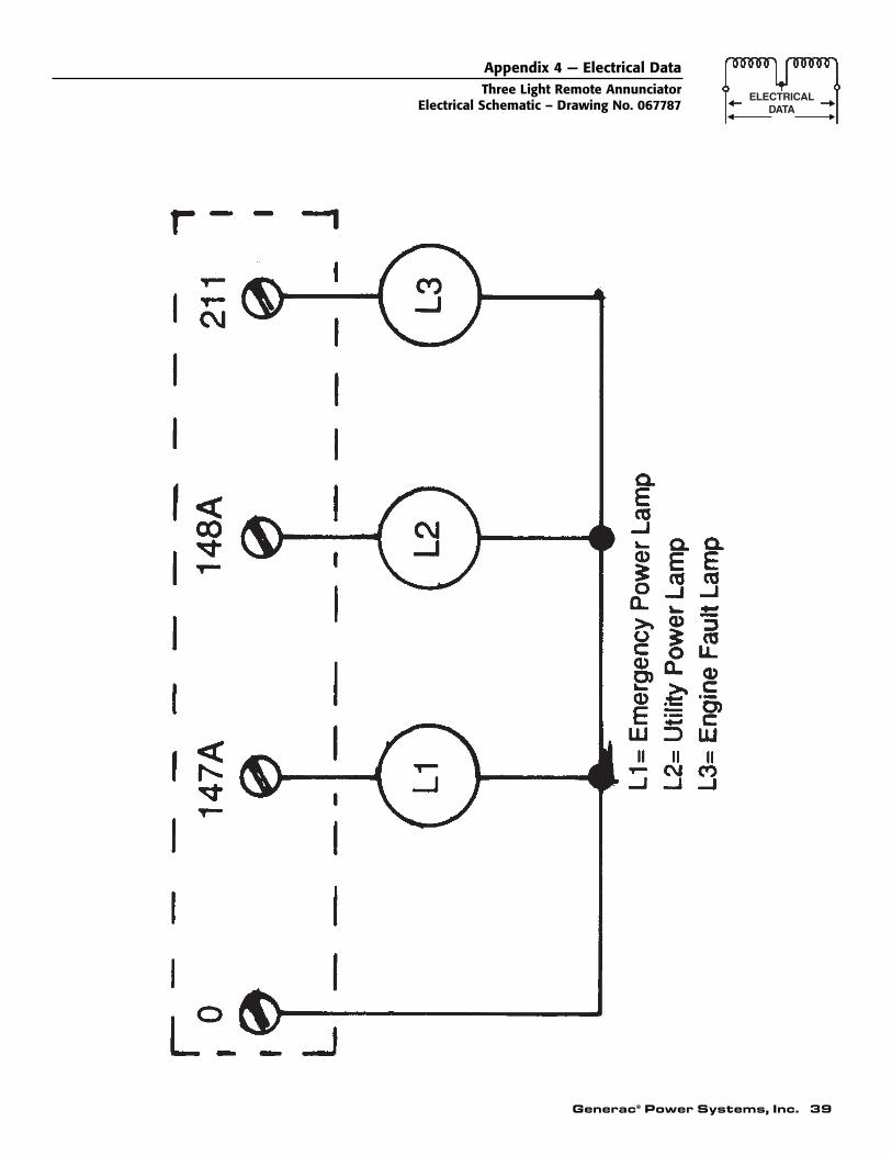
Appendix 4 — Electrical DataThree Light Remote Annunciator
Electrical Schematic – Drawing No. 067787
Generac® Power Systems, Inc. 39
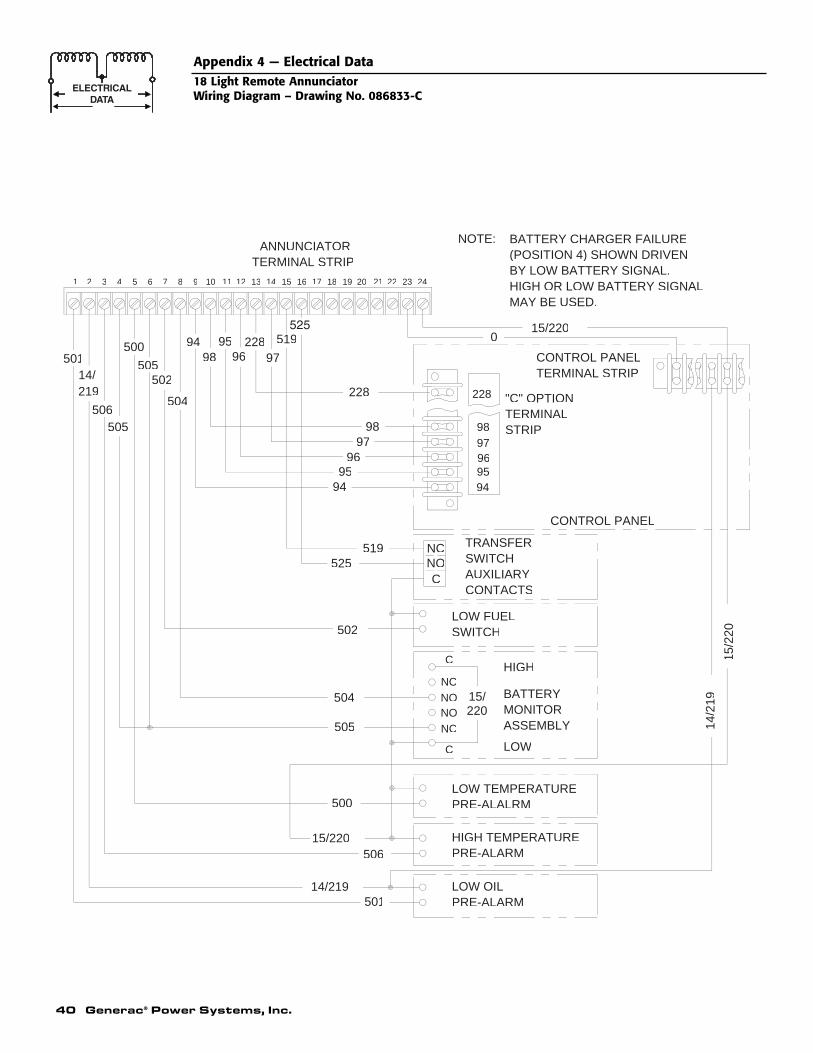
14/2
19
519
525519
015/220
STRIP
220
TERMINAL STRIPANNUNCIATOR
219
15/2
20
"C" OPTIONTERMINAL
CONTROL PANEL
TERMINAL STRIPCONTROL PANEL
15/220
97
228
9695
98
94
504
502
500
505
506
14/219501
MAY BE USED.HIGH OR LOW BATTERY SIGNALBY LOW BATTERY SIGNAL.(POSITION 4) SHOWN DRIVENBATTERY CHARGER FAILURENOTE:
C
NCNONONC
C
15/
LOW
PRE-ALARMLOW OIL
PRE-ALARMHIGH TEMPERATURE
PRE-ALALRMLOW TEMPERATURE
ASSEMBLYMONITORBATTERY
HIGH
SWITCHLOW FUEL
CONTACTSAUXILIARYSWITCHTRANSFER
505
CNONC
97228
9695
9894
504
502
505
500
506
14/501
242322212019181716151413121110987654321
228
9495969798
40 Generac® Power Systems, Inc.
Appendix 4 — Electrical Data18 Light Remote AnnunciatorWiring Diagram – Drawing No. 086833-C
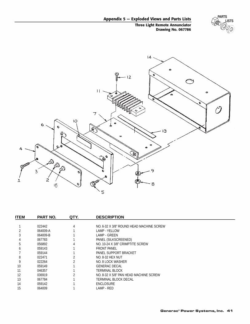
ITEM PART NO. QTY. DESCRIPTION
1 022442 4 NO. 6-32 X 3/8” ROUND HEAD MACHINE SCREW2 064009-A 1 LAMP - YELLOW3 064009-B 1 LAMP - GREEN4 067783 1 PANEL (SILKSCREENED)5 056892 4 NO. 10-24 X 3/8” CRIMPTITE SCREW6 059143 1 FRONT PANEL7 059144 1 PANEL SUPPORT BRACKET8 022471 2 NO. 8-32 HEX NUT9 022264 2 NO. 8 LOCK WASHER
10 059149 1 GENERAC DECAL11 046357 1 TERMINAL BLOCK12 036919 2 NO. 8-32 X 5/8” PAN HEAD MACHINE SCREW13 067784 1 TERMINAL BLOCK DECAL14 059142 1 ENCLOSURE15 064009 1 LAMP - RED
Appendix 5 — Exploded Views and Parts ListsThree Light Remote Annunciator
Drawing No. 067786
Generac® Power Systems, Inc. 41
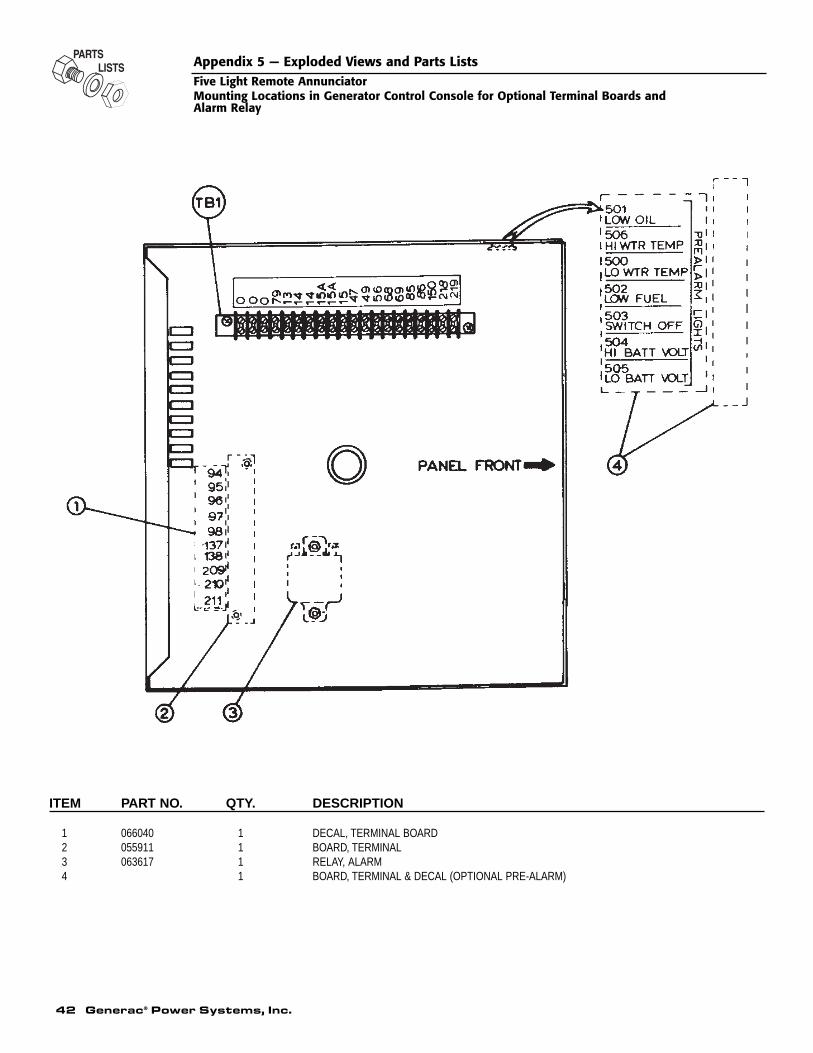
ITEM PART NO. QTY. DESCRIPTION
1 066040 1 DECAL, TERMINAL BOARD2 055911 1 BOARD, TERMINAL3 063617 1 RELAY, ALARM4 1 BOARD, TERMINAL & DECAL (OPTIONAL PRE-ALARM)
Appendix 5 — Exploded Views and Parts ListsFive Light Remote AnnunciatorMounting Locations in Generator Control Console for Optional Terminal Boards and Alarm Relay
42 Generac® Power Systems, Inc.
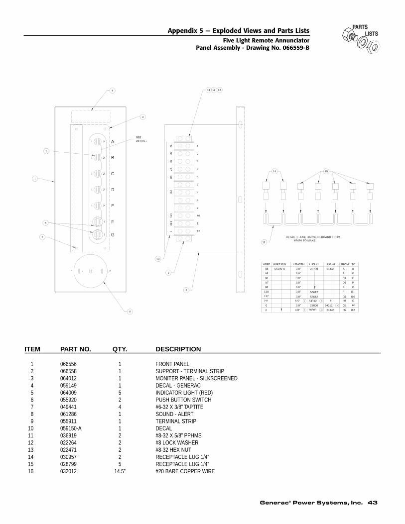
ITEM PART NO. QTY. DESCRIPTION
1 066556 1 FRONT PANEL2 066558 1 SUPPORT - TERMINAL STRIP3 064012 1 MONITER PANEL - SILKSCREENED4 059149 1 DECAL - GENERAC5 064009 5 INDICATOR LIGHT (RED)6 055920 2 PUSH BUTTON SWITCH7 049441 4 #6-32 X 3/8” TAPTITE8 061286 1 SOUND - ALERT9 055911 1 TERMINAL STRIP
10 059150-A 1 DECAL11 036919 2 #8-32 X 5/8” PPHMS12 022264 2 #8 LOCK WASHER13 022471 2 #8-32 HEX NUT14 030957 2 RECEPTACLE LUG 1/4”15 028799 5 RECEPTACLE LUG 1/4”16 032012 14.5” #20 BARE COPPER WIRE
16
15
10
9
2
8
7
6
1
5
4
3
11 12 13
14
LENGTHWIRE WIRE P/N
A0
211
137
138
55199-A
95
TO
3.0"
4.0"
6.5"
3.0"
3.0"
3.0"
3.0"
3.0"
LUG #1
28800
28799
LUG #2 FROM
A1
H2
G2
H1
F1
D1
C1
B1
0
E13.0"
3.0" 56612 G1
61446
64312
61446
A
A A64312
A28800 I12
H2
I7
I10
I11
I5
I4
I3
I2
I1
21
21
21
21
21
21
A
B
C
D
E
F
G
SEEDETAIL 1
1 2+ -H
9495
9697
98211
137138
0
1
2
3
4
5
6
7
8
9
10
11
12
DETAIL 1 - USE HARNESS BOARD FROM 63494 TO MAKE
21
56612
94
98
97
96
Appendix 5 — Exploded Views and Parts ListsFive Light Remote Annunciator
Panel Assembly - Drawing No. 066559-B
Generac® Power Systems, Inc. 43
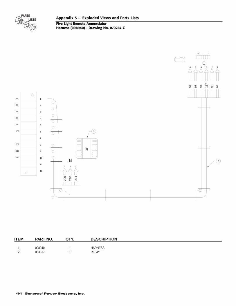
ITEM PART NO. QTY. DESCRIPTION
1 098940 1 HARNESS2 063617 1 RELAY
1
2
1
2
3
4
5
6
7
8
9
10
11
94
95
96
97
98
137
209
211
210
12
1 7 4
209
210
211
3 12456
97 95 94 137
96 98
C
16
B
B
Appendix 5 — Exploded Views and Parts ListsFive Light Remote AnnunciatorHarness (098940) - Drawing No. 070287-C
44 Generac® Power Systems, Inc.
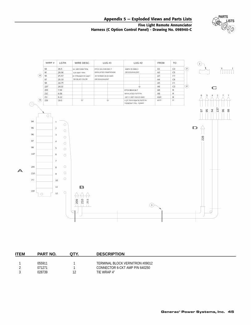
Generac® Power Systems, Inc. 45
ITEM PART NO. QTY. DESCRIPTION
1 055911 1 TERMINAL BLOCK VERNITRON #090122 071271 1 CONNECTOR 6-CKT AMP P/N 6402503 028739 12 TIE WRAP 4”
1
3
2
A
A
A
B
LUG #2
AMP# 35 0980-3
INSULATED FASTON
.187 X .020" #18-22 AWG
WIRE #
137
209
211
210
97
211
210
209
137
98
96
95
94
97
98
94
96
95
4
11
12
10
9
8
7
6
5
6.12
3
2
1
25.19
24.75
24.31
7.00
6.56
26.5
26.06
25.62
LGTH.
DK BLUE COLOR
WIRE DESC.
#18 AWG 300V
UL 1007/1569 TEW
16 STRANDS/30 AWG
OR EQUIVALENT
LUG #1
ETC# AA-2190-06X-T
INSULATED SNAPSPADE
#6 SCREW 18-22 AWG
OR EQUIVALENT
BA10
A4
A8
A9
A5
A6
A1
A2
A3
FROM
C6
B
B
C1
C3
C4
C2
C5
TO
228
228 19.5 0.25" PIGGYBACK FASTON A12 DGENERAC P/N - 028800
A
210
209
211
B
9497 95 96137
98
C
6 5 4 3 2 1
6 1
228
D
Appendix 5 — Exploded Views and Parts ListsFive Light Remote Annunciator
Harness (C Option Control Panel) - Drawing No. 098940-C
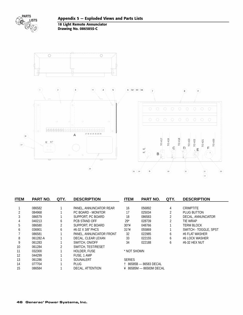
ITEM PART NO. QTY. DESCRIPTION
1 086582 1 PANEL, ANNUNCIATOR REAR2 084968 1 PC BOARD - MONITOR3 086579 1 SUPPORT, PC BOARD4 040213 6 PCB STAND OFF5 086580 2 SUPPORT, PC BOARD6 036901 6 #6-32 X 3/8” PHCS7 086581 1 PANEL, ANNUNCIATOR FRONT8 061282-A 1 DECAL, CLEAR LEXAN9 061283 1 SWITCH, ON/OFF
10 061284 2 SWITCH, TEST/RESET11 032300 1 HOLDER, FUSE12 044299 1 FUSE, 1 AMP13 061286 1 SOUNALERT14 077704 1 PLUG15 086584 1 DECAL, ATTENTION
ITEM PART NO. QTY. DESCRIPTION
16 056892 4 CRIMPTITE17 025034 2 PLUG BUTTON18 086583 2 DECAL, ANNUNCIATOR
29* 028739 2 TIE WRAP30†¥ 048766 1 TERM BLOCK31†¥ 055869 1 SWITCH - TOGGLE, SPST
32 022985 6 #6 FLAT WASHER33 022155 6 #6 LOCK WASHER34 022188 6 #6-32 HEX NUT
* NOT SHOWN
SERIES† 86585B — 86583 DECAL¥ 86585M — 86583M DECAL
17
15
32 4161 5
13914 10
876
10 11
12
18
23222120191817
1
21 2
2
1
2
1
23
1
A
FD
TO
#19
TO
#18
TO
#23
TO
#21
TO
#22
TO
#20
TO
#17
C
30
31
G21G
1H
H2
32 33 34
46 Generac® Power Systems, Inc.
Appendix 5 — Exploded Views and Parts Lists18 Light Remote AnnunciatorDrawing No. 086585$-C

Appendix 6 — NotesFive Light Remote Annunciator
Generac® Power Systems, Inc. 47
48 Generac® Power Systems, Inc.
Appendix 6 — NotesFive Light Remote Annunciator

Generac® Power Systems, Inc. 49
Appendix 6 — NotesFive Light Remote Annunciator

Part No. 0C4205
GENERAC® POWER SYSTEMS, INC.P.O. BOX 8
WAUKESHA, WI 53187
Revision B (09/27/02) Printed in U.S.A.