Embed Size (px)
Citation preview

Menzi Muck AG Telefon +41 (0)71 727 12 129451 Kriessern/Switzerland Fax +41 (0)71 727 12 13 www.menzimuck.com [email protected]
Menzi Muck A20
Operator’s manual
Edition 01/11
Spare parts list

Edizione 01/11– Revision 00 2 -
INDEX 1. Introduction ...................................................................................... 4 2. Identification data ............................................................................. 5 3. Technical Characteristics .................................................................... 9 4. Standard equipment and accessories .................................................. 11 5. Supplies ......................................................................................... 12 6. Running the excavator ..................................................................... 13
6.1 Running direction ........................................................................ 13 6.2 Releasing the driven wheels ......................................................... 14
6.2.1 Releasing the gearmotor ......................................................... 14 6.2.2 Locking the gearmotor ........................................................... 14
7. Vehicle transport ............................................................................. 15 7.2 Loading onto flat-beds or trailers without ramps .............................. 15 7.3 Transport by helicopter ................................................................ 17
8. Lifting weights ................................................................................ 18 9. Advice and regulations for the use of the excavator .............................. 21
9.1 Special requirements for operators of construction machines ............. 21 9.2 Advice for new operators of “spider” type machines ......................... 21 9.3 Advice and regulations for the use of the excavator ......................... 22
10. The cabin and the commands .......................................................... 24 10.1 Descrizione generale: ................................................................ 24 10.2 Dashboard ............................................................................... 25 10.3 Servo commands ...................................................................... 26 10.4 Pedals ..................................................................................... 26 10.5 Steering ................................................................................... 27 10.7 Movement of the boom articulation .............................................. 28 10.8 Using accessories to mounting on the arm. ................................... 29 10.9 Fuse box: ................................................................................. 30 10.10 Driver seat (Fig.43) ................................................................. 30
11. Engine bonnet opening and access to the internal parts of the excavator 31 11.1 Engine bonnet opening ............................................................... 31 11.2 Accessing internal parts of the excavator ...................................... 32 11.3 Closing the rollbar ..................................................................... 33
12. Filling the main tank with fuel .......................................................... 34 13. Starting up the excavator ............................................................... 35
13.1 Starting up ............................................................................... 35 13.2 Operations at the end of work ..................................................... 35
14. Maintenance ................................................................................. 36 14.1 General information ................................................................... 36 14.2 Daily maintenance operations ..................................................... 36 14.3 Periodical maintenance operations (every 200 hours of work) .......... 37 14.4 Periodical maintenance operations (every 1000 hours of work) ........ 38 14.5 Information about maintenance operations ................................... 40

Edizione 01/11– Revision 00 4
1. Introduction
Dear customer, we compliment and thank you for having chosen our company. We have prepared this manual as a guide for the correct and safe use of the machine and its rational maintenance. Constant observance of the standards contained in this manual guarantees the best performance, low running costs, long machine life and prevents the most common causes if accidents which may arise during working or maintenance. We therefore recommend that you to read all parts of this manual carefully and scrupulously observe the instructions indicated on the following pages. All of our spare parts are exclusively available from our distributors or our headquarters. We ask you to please always kindly specify the serial number of your excavator and the model and spare part code which you will find in the “spare parts” catalogue supplied enclosed here; in this way we will be able to satisfy all of your requests rapidly. For answers to any other questions, curiosities, information concerning old models, suggestions or ideas to improve our products, our Customer service is always at your disposal on the following telephone number:
A copy of this manual is supplied with every machine. The descriptions and illustrations in this publication are in no way binding.
Edizione 01/11– Revision 00 5
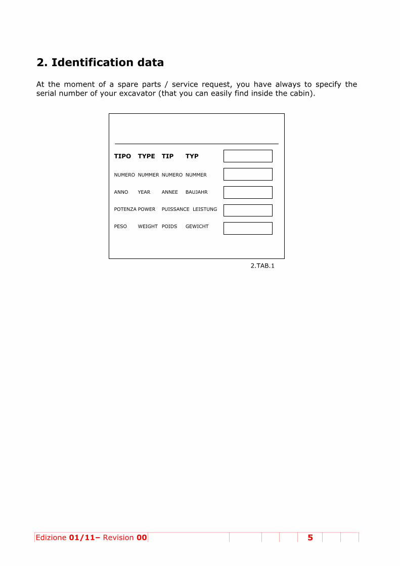
2. Identification data At the moment of a spare parts / service request, you have always to specify the serial number of your excavator (that you can easily find inside the cabin).
2.TAB.1
TIPO TYPE TIP TYP NUMERO NUMMER NUMERO NUMMER ANNO YEAR ANNEE BAUJAHR POTENZA POWER PUISSANCE LEISTUNG PESO WEIGHT POIDS GEWICHT

Edizione 0
3. Tec 3.1 Struc
• Loahig
• Joimastee
• Te• Ba
harcordiam
3.2 EnginSee the handbook 3.3 Noise
• Acothe
Europ 3.4 Per
• Max• Max
26%
3.5 Tract• Rea
and 3.6 Hydra• Triple• Deliv• Hydr
and a• Hydr• Anti-• Calib• Rotar
nega• Rotat• Hydr• Oil he• Hydr• Hydr
01/11– Re
hnical
ctures ad bearingh mechanints equide of temel. mpered ansic bea
rdened, rected at meter 490
ne enclosed
k
e level oustic leve followingpean direc
rformancximum speximum %
tion ar wheel dd mechani
aulic wore main fixevery capacaulically dauxiliary aaulically dshock, ant
bration of try hydraultive braketion speedaulic cylineat exchanaulic oil taaulic oil ci
evision 00
Chara
g structurical strengpped witmpered a
nd groundaring tytempered 10 ton/m0mm).
Use & M
el in comp standardsctive 2000
ce eed: 2.6 Kgradient
rive throucal release
rk circuit ed engine
city 66 lit/mdriven tripaccessory adriven triplti-cavitatiothe generalic motor we safety ded: 8 rpm ders with nger coupank capacircuit capa
0
acteris
re made ogth steel. th bushend groun
d pins pe, wit toothin
m (externa
aintenanc
pliance whs
0/14/CE
Km/h possible
ugh two whe comman
capacity pmin (Maximle distribuat the endle distributon and preal work cirwith axial evice.
case hardled to a wty: 38 lt
acity: 50 lt
stics
of
es d
th g al
ce
it
e:
heel reducnded by a
pump. mum delivution valved of the artion valveessure limrcuit: 180 pistons co
dened rodswater radia
t.
cers, comphydraulic
very at 24e for the cm. .
mitation va bar oupled to a
s and traveator.
plete with pedal.
00 RPM). control of
lve on eve
an epicycl
el limit bra
9
3
negative b
boom, tra
ery elemen
oid reduce
akes.
3 Fig.1
brake
anslation
nt.
er with a

Edizione 0
Tearing f
Penetrat
3.7 Posit• Self-Delivery • 7 sec• Maxim• Posit 3.8 Elect• Powe
01/11– Re
force (Iso
ion force
tioning hycompensa capacity:ction distrimum calibioning cyli
rical syster supply v
evision 00
o 6015):
(Iso 601
ydraulic cated pump: 9.5 lit/mibution vabration of tinders equ
tem voltage. 12
0
1740 Kg (
15): 1070
circuit p with gearmin at 2400
lve compothe distribuipped wit
2 V - 60 A
(3.6 Fig. 1
Kg (3.6 F
rs 0 RPM osed of elebution valvh case har
A/h
1)
Fig. 2)
ectrical valve: 170 bardened rod
lves. ar ds and saf
10
fety valve.
3.6 Fig.1
3.6 Fig. 2
.

Edizione 01/11– Revision 00 11
3.9 Weights * • Working mass 1900 Kg (without bucket, foot; oil-full; fuel tank at the minimum
level) it is possible a tolerance of (+-) 3% * NOTE: The weights refer to the version without non-standard accessories. Maximum working temperature: +40°C Minimum working temperature: -15°C
4. Standard equipment and accessories • Roll-over protection, easy to tip hydraulically, work light and acoustic warning
device. • Work commands/hydraulic remote commands grouped onto two levers and
two hydraulic pedals. • Accelerator command by lever. • Positioning commands by electrical buttons. • Specific clawed wheels for hydraulic rotations. • 70015 driven wheels. • Adjustable seat with safety bell. • Predisposed to take hydraulic hammer.
Lighting The excavator is equipped with proper lights to operate where the ambient temperature is not sufficient. If the operator requires more light, inform the manufacturer who will supply lights of the capacity required.

Edizione 01/11– Revision 00 12
5. Supplies • Main fuel tank (including reserve): 30 Lt. • Radiator water: 07 Lt. • Motor lubrication system (engine sump, filter etc..) see enclosed handbook. • Rotation reducer oil: 0.5 Lt. • Towing reducer oil: 0.2 Lt. • Hydraulic system oil: 38 Lt. 5.1 Front and rear tyre pressures: Front (idle): 5 Bar Rear (driven): 6 Bar 5.2 Recommended fuels and products All types of fuels or oils which correspond to the characteristics shown in Table 1 on the left here. The list of lubricants is purely indicative and refers to products of equivalent quality. A=lubricant; B=reducer oil; C=hydraulic oil; D =motor oil.
TYPE A B C D AGIP AUTOL TOP 2000 ROTRA MP 80W90 OSO 46 SIGMA FEO
10W40 ASEOL CALLIT EP 10/42 TOPRESS 11/118 HYDRO HVI
16 - 705 PERLA LD 15 – 75
BP ENERGREASE L21 ENERGREAR 80/90 BARTRAN SHFS46 BP VANELLUS FE 10/40
ESSO MULTI PURPOSE GREASE MOLY
GEAR OIL GX80 W90
NUTO H 46 UNIFARM 10/30
MOBIL MOBILREASE HP MOBILUBE HD85W – 90A
MOBIL DTE 25 M DELVAC SUPER FL 10W/40
ROLOIL FILCAR 2 VARIAX 140 GAVIA GAVIA HD30 AG 228 GL5 80W/90 ISO 46 10W/40 PANOLIN MOLYGREASE 23 SUPERDUTY G1 –
5 90 HLP UNIVERSAL
37 UNIVERSAL FE
10W/40 SHELL RETINAX AM SPIRAX HD 90 SHELL HYDROL
HV46 MULITCHANTI ER
10W/40 STRUB GRASSO A LUNGA
DURATA UNIVERSAL VULVOLUBE SUPERMULTI
VALVOLINE MULTILUBE MO - 2 X – 18/MD 80W/90
ULTAMAX AW 46 HVI
HDS TOPFILE 10W/40
Tab 1: Lubrificants

Edizione 01/11– Revision 00 13
6. Running the excavator
6.1 Running direction The correct running position for mobile spider type excavators is the following:
• Position the arm towards the driven wheels in the collection position (6.1 Fig. 1).
• Align the brackets of the front “idle” wheels so that they remain parallel to allow the machine to steer.
6.1 Fig. 1
Fix the magnetic flasher (standard equipment) to the upper part of the cabin, and connect the plug (6.1 Fig. 2) to the socket on the cabin (6.1 Fig. 3)
6.1 Fig 2 6.1 Fig.3 • The excavator must not exceed 25 cm from the ground (6.1 Fig.1).
• The arm must not exceed 2.80 m in height.
Emergency and parking brake; in case of any failure to the excavator hydraulic system, use the machine emergency boom as a brake. When the excavator stops, always rest the boom on the ground as a parking brake.

Edizione 0
ATThe mob
6.2 RelFor speciaTo do this6.2.1 Rel• Rotat
Fig.1• Hold
time idle
6.2.2 Loc• Rotat
Fig.1 • Hold
time now
01/11– Re
TENTIONile excav
leasing al requirems, proceedleasing thte the boo). the part a unscrew t
cking thete the boo).
the part a screw thelocked.
evision 00
N: vators are
the driments, it is as followshe gearmom toward
and pull fithe part (
gearmotom toward
and pull fie part (2
0 5
e not type
iven whs possible s:
motor ds the rea
irmly (1 -2 - 6.2 Fig
tor ds the rea
irmly (1 -- 6.2 Fig.
500-M
e tested f
heels to conver
ar wheels
6.2 Fig. 2g. 2) fin it
ar wheels
6.2 Fig. 2. 2) in its
for circula
t the drive
and apply
2) on the ts original
and apply
2) on the original p
ation on t
e wheels t
y a force t
gearmoto position.
y a force t
gearmotoposition. T
2
14
the road.
o idle.
to raise th
r and in t The whee
to raise th
r and in tThe drive
1
hem (6.2
he same el is now
hem (6.2
he same wheel is
6.2 Fig. 1
6.2 Fig. 2

Edizione 01/11– Revision 00 15 1500-M
ATTENTION: Do not use the reducer release for towing the excavator, so as to avoid exceeding the speed of 7 km./h. permitted by the two reducers in the idle position. The EUROMACH company is not responsible for damage to objects and/or to persons if the warnings above are not followed.
7. Vehicle transport 7.1 Loading the excavator onto a transportation trolley Only use special transport trolleys (min. length 4 m.) equipped with ramps (7.1 Fig. 1). • The arm must be in the collection position towards the rear side. • Align the machine to the trolley. • Start up the excavator and proceed with care until the operation is complete. • Rest the arm in the rest position on the flat-bed (7.1 Fig. 1).
Block the wheels with the special wedges (not standard equipment) (1- 7.1 Fig.1). • Switch off the engine
Tie the machine with bands or safety cables (2- 7.1 Fig.1).
7.1 Fig 1 The operator have the responsibility to find the correct fixing points on the machine and to assure that it is not a danger for the circulation during the transport.
ATTENZIONE: Never exceed an overall height of 4 m. when the machine is on the trolley.
7.2 Loading onto flat-beds or trailers without ramps
The machine can be positioned on trailers or lorry flat-beds only by lifting with a crane. • It is dangerous to remain inside the cabin during lifting. • The flat-bed must have a minimum width of 2.5 m. and a minimum length of 6 m. to accommodate the machine (7.2 Fig. 1).

Edizione 0
• Once thewedges (n• Hook th
• Thecasmo
• It ilift
01/11– Re
e excavatonot standae cables to
ATTENZIe crane mse a weigounted duis dangering mach
7
evision 00
or has beeard equipmo the fron
IONE: must haveht major
uring the rous to rehine.
7.2 Fig 2 e
0 15
en positionment), to pt and rear
e a minim of the ex loading)emain wit
3
500-M
ned on theprevent anr brackets
mum loadxcavator . thin the w
e lorry, fixny movem of the exc
capacity and even
working r
crane points
1.front l
2.of strboom 2)
3.pointsthe aadaptemachiaccessanchostanda
the wheeent (7.2 Fcavator (7
y of 2500 ntual acce
radius of
For the consides:
Rotate thegs Open the
roke and as in the
Hook to s (2 on tharm) anded to thne andsories (7.2red pointsard equipm
16
els with theFig. 1). .2 Fig. 1)
Kg (in eaessories
the traile
loading wr the f
he arm tow
first boomclose the
e picture (
the 3 ahe legs ad use the weight the 2 Fig 2 e 3s are optioment!).
e special
7.2 Fig. 1
ach
er
with the following
ward the
m at end e second (7.2 Fig.
anchored nd 1 on
he hook of the eventual
3). The 3 onal (not

Edizione 01/11– Revision 00 17 1500-M
7.3 Transport by helicopter FOR ANY TRANSPORTATION BY HELICOPTER ASK MENZI MUCK FOR THE WEIGHT REFERENCE TABLE. ATTENTION:
Do not risk hazardous transportation. The EUROMACH company is not responsible for damage to persons or objects deriving from transportation performed without its approval.
WEIGHTS
Edizione 0
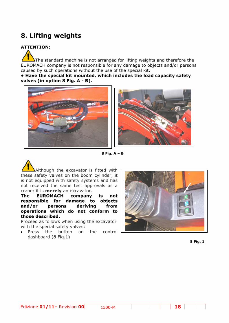
8. Lift ATTENTI
TheEUROMACcaused by• Have thvalves (i
Alththese safeis not equnot receivcrane: it iThe EUresponsiand/or operationthose deProceed awith the s• Press
dashbo
01/11– Re
ing we
ON:
e standardCH company such opehe specian option
hough theety valvesuipped witved the ss merely
UROMACHble for
personns whichscribed. s follows w
special safethe bu
oard (8 Fig
evision 00
eights
d machineny is not rerations wial kit mou8 Fig. A -
e excavatos on the bh safety same test an excava
H compdamage
ns derh do no
when usinety valvesutton ong.1)
0 15
is not arresponsibleithout theunted, wh- B).
8
or is fitteboom cylinsystems an approvalsator.
pany is e to oriving
ot confor
g the excas: n the c
500-M
ranged fore for any d use of thehich inclu
8 Fig. A – B
d with nder, it nd has s as a
not bjects
from rm to
avator
control
lifting wedamage toe special k
udes the l
ights and o objects akit. oad capa
18
therefore and/or per
acity safet
the rsons
ty
8 Fig. 1

Edizione 0
• The macpositionedthe four sas to avoiexcavator
• Lower th• The heig• Verify th
01/11– Re
chine mustd to the wiupport pod problem
r (Fig.8 Fig
he feet to ght of the he ground
evision 00
t have theidest positints are as
ms of instag. 2).
the groun machine f solidity u
0 15
e four braction, so ths in figurebility of th
8
nd and chefrom the gnder the a
500-M
ckets at , so
he
Fig. 2
eck that thground muanchored p
hey are weust not excpoints.
ell anchoreceed 30 cm
19
ed. m. (8 Fig.3
3).
8 Fig. 3

Edizione 0
AT- If the bany kinds- Make aand the mA When thebe indicat
Thverify thindicated The maximtraverse lvalues at The diagra
Wemachine.from the The liftingAsk for t
01/11– Re
TENTIONbrackets cs of liftinll of the cmaximum
maximumted by an a
he buzzerhat the d on the l
mum admifting tablthe specif
ams show
eights are. So the w nominal
g point is she appos
evision 00
N: cannot beg operati
calculatiom foresee
m admissibacoustic s
r is only aweight loading ta
missible wele (8 Fig. fied load ra
n here hav
e consideweight fo loading t
situated onsite hook
0 15
e positionion in any
ons necesen weight
ble weightignal.
an auxilialoaded isables.
eights are3). Do noadii and he
ve been p
ered withor the loato have t
n the boom homolog
500-M
ned as dey event. ssary to at.
is exceed
ary devics correct
shown inot try to leights.
repared in
hout buckading or he net lo
m at the pgated for
escribed a
ascertain
ded on the
e for thet in rela
the longiift or hold
n complian
ket or otlifting deading tha
oint wherethe loadi
above, do
the type
machine,
operatorationship
tudinal liftd any weig
nce with IS
her accesevice musat can be
e the shovng (optio
20
o not perf
of cables
this cond
r and he to the
ting tableght excee
SO 10657
ssories ost be sub lifted.
vel is fixedon).
form
s to use
dition will
have to weight
and the ding the
7.
onto the btracted
d.

Edizione 01/11– Revision 00 21 1500-M
9. Advice and regulations for the use of the excavator
9.1 Special requirements for operators of construction machines
• The excavator may only be driven by persons possessing good working experience of “spider” type operating machines. • The ordinary maintenance can be performed by the owner of the machine without any difficulty; for more complicated operations we advise contacting the Service Centers listed at the beginning of this manual. • It is necessary to follow the procedures advised in this manual carefully for the use, maintenance and transport of the excavator. • Always use original spare parts and the lubricants recommended by the same company (see table).
• Variations or alterations to the functions of the excavator even by the authorized Service Centers are not permitted. (should this happen, the guarantee is no longer valid).
• Do not try to be an expert. Consult one of the Service Centers for any mechanical operations not foreseen by this manual.
9.2 Advice for new operators of “spider” type machines
These machines are very particular and are completely different to any other type of mobile excavator given that they do not have stabilizers (three point machines, track driven etc.). We therefore advise a brief trial period at the headquarters or at your building sites so as to learn the particular notions which distinguish the above mentioned machines. Generally, however, follow the following procedure: • Initially, work only on flat ground. • Position the machine with the four stabilizer brackets very wide so as to prevent the excavator fro over-balancing and tipping itself over (Fig. 12).
9.2 Fig. 1
• Always keep the machine close to the ground.

Edizione 0
• Move tpersons) p
9.3 Adv
9.3The regulaservicing the indispits long lifWhen thethe sales supply themain instrthe use anThese instsummarizfollows: • Make cepersons inbefore sta• Keep pethe elevat• Mobile transporta• Constan• Pay max• Never tbetter, alwlimbs insidany exter• Do ninterventithis manu• Do notthere is a• Never le• Do not l• Before necessaryno one ca
ATAlways fthe excav • Damage(always u• Clean th• To avoirods.
01/11– Re
he commpresent in
vice and
3.1 Use rear checkinof your ex
pensable cofe. machine office perse customeructions innd maintetructions azed in the
ertain thatn the manarting the ersons far ted tools stype exc
ation on vently check ximum attry to makways sit inde the cabnal dangeot start ons on th
ual. run the lack of aireave the meave the kperformin
y to switchn start it w
TTENTIONfasten thevator.
ed parts mse origina
he excavatd damage
evision 00
ands care the worki
d regul
egulationng and xcavator aonditions f
is deliveresonnel er with thenherent tonance. are list which
there areeuver zonmachine. away from
so as to avcavators aehicles). the work z
tention to ke the macn the drivibin to redrs to a mi
up, usee machine
engine inr.
machine wkeys in theng any mh off the ewithout pe
N: e securit
must be sul spare pator after ee from cor
0 15
efully, paying radius
lations
ns
re for
ed,
e
no e
m void damaare not t
zone to avunsafe wachine worng seat. Iuce the rinimum. e, re-supe without
enclosed
ith the enge dashboa
maintenancengine. Maermission
y bells a
ubstituted rts). ach time irrosion aft
500-M
ying atten of the ma
for the
ge (see 9.type teste
void the poalls, fallingk or to usn all circuisk of exp
pply or having ex
d places o
gine runniard. ce operatiake sure a(9.3.1 Fig
pplied on
in good ti
t is used. ter long p
ntion to aachine.
use of
.3.1 fig.1)ed to cir
oints of mg objects ase its toolsumstancesosure to
perform xamined
or where
ing.
ion it is also that .2).
n the sea
ime so as
periods of
avoid obst
the exc
. culate on
ost dangeand unfores in unsuit, keep you
at, before
to preven
disuse, gr
22
tacles (ob
cavator
9.3.1 Fign the roa
er. eseen landtable posiur head, b
9.
e operatin
nt greater
rease the
bjects or
r
g 1 ds (See
slides. tions, or
body and
3.1 Fig. 2
ng with
damage
cylinder

Edizione 01/11– Revision 00 23 1500-M
• If there are any loose screws contact the Service Centre. • If any hydraulic joints become loose, tighten them carefully (or contact the Service Centre). • Immediately substitute any damaged hydraulic pipe work not concerning the engine. • Clean the greaser thoroughly before using it. • Avoid climbing on the excavator when it is being moved by persons other than the operator. • When the hydraulic hammer is being used avoid opening the front window. • Do not mix different types of lubricants see the lubricant table); lubricate according to the prescribed maintenance program. • Make sure to eliminate, collect and dispose of degraded oils through specialized bodies. This is important in conserving the environment and in the fight against pollution.
When using the hydraulic hammer we advise against extracting the rod of the second hydraulic arm so as to avoid dangerous stress to the machine. Ask the for the characteristics of the most suitable hammer for your machine (see accessories). 9.3.2 Dismounting the front idle wheels Whenever the excavation work is obstructed by the front wheels (9.3.2 Fig. 1) proceed as follows: • Remove the two split pins of the wheel pins. • Slide out the lock pin from the wheel pins. • Slide the two wheel pins out of the hole (9.3.2 Fig. 1). • Position the wheels above the brackets in the support.
9.3.2 Fig. 1
ATTENTION: Only experienced persons must use the machine. The EUROMACH company is not responsible for damage to persons or things consequent on the improper use of the machine. Follow the advice in this manual scrupulously.
At the end of the digging operation, if necessary, re-place the idle wheels to move the machine. Don’t forget to lock the pin using the security split pins.

Edizione 01/11– Revision 00 24 1500-M
10. The cabin and the commands
10.1 Descrizione generale: This is constructed in compliance to the tipping prevention ROPS standard according to the DIN ISO 3471 standard. The rollbar can be tipped forward by using a manual hydraulic pump for maintenance and repair work. • The driver’s seat is equipped with a safety belt.
ATTENTION: When the left arm-rest is in the raised position all of the excavator commands are disabled. The commands can be divided into: • The right hand servo command and the left hand servo command for arm movements and rotation of the machine. • Two hydraulic pedals which command the extension of the arm, the traction of the machine and the various optional accessories (demolition hammer, directional bucket, etc..) • The electrical buttons positioned on the two servo commands permit the adjustment of the front and rear brackets of the machine.
Edizione 01/11– Revision 00 25 1500-M
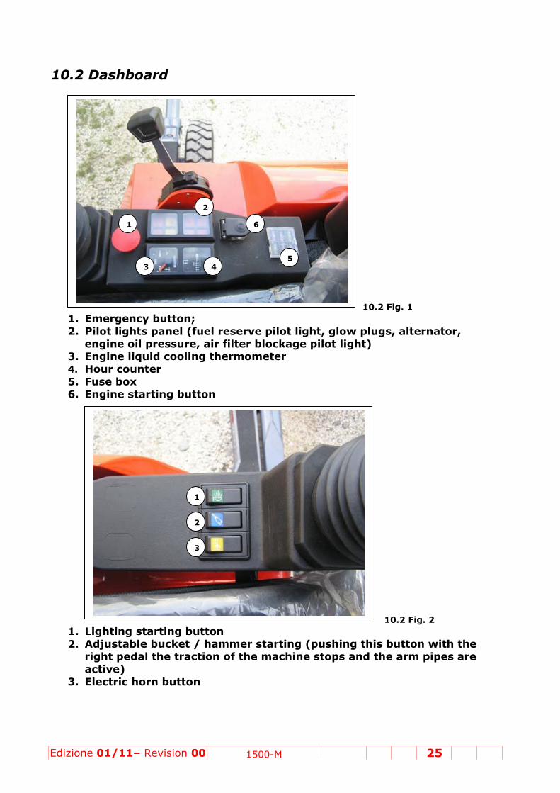
10.2 Dashboard 10.2 Fig. 1
1. Emergency button; 2. Pilot lights panel (fuel reserve pilot light, glow plugs, alternator,
engine oil pressure, air filter blockage pilot light) 3. Engine liquid cooling thermometer 4. Hour counter 5. Fuse box 6. Engine starting button 10.2 Fig. 2 1. Lighting starting button 2. Adjustable bucket / hammer starting (pushing this button with the
right pedal the traction of the machine stops and the arm pipes are active)
3. Electric horn button
6
5 4 3
2
1
1
2
3

Edizione 01/11– Revision 00 26 1500-M
Manual Accelerator. The engine ignition should be always in the min. rpm. Wait some minutes befor accelerating in case of very cold temperatures. 10.2 Fig. 3
10.3 Servo commands Right hand servo command: • When the lever is pulled the first arm is raised (1 – 10.3 Fig.1). • When the lever is pushed (2 – 10.3 Fig. 1) the arm is lowered. • When the lever is turned to the right (3 - 10.3 Fig. 1) the bucket opens. • When the lever is turned to the left (4 - 10.3 Fig. 1) the bucket closes. Left hand servo command: • When the lever is pulled (1 - 10.3 Fig.2) the second arm closes. • When the lever is pushed (2 - 10.3 Fig.2) the second arm opens. • When the lever is turned to the right (3 - 10.3 Fig.2) the turret and the arm rotate clockwise through 360°. • When the lever is turned to the left (4 - 10.3 Fig.2) the turret and the arm rotate in an anti-clockwise direction.
10.3 Fig. 1 10.3 Fig.2
10.4 Pedals Left hand pedal (10.4 Fig.2): • When pressure is applied to the front of the pedal (A), the rod of the second arm extends. • When pressure is applied (B) to the pedal the rod of the second arm reenters. Right hand pedal (10.4 Fig. 1): • When pressure is applied to the front (A) the machine advances.* • When pressure is applied to the rear (B) the machine reverses. *

Edizione 01/11– Revision 00 27 1500-M
*The drive direction is considered with the machine position with the arm towards the driving wheels. When the adjustable bucket / hammer function is (button, see figure cap.10.2) the oil is deviate from the traction to the pipes at the end of the boom.
10.4 Fig. 1 10.4 Fig.2
ATTENTION: When the excavator is pulled or pushed with its own arm, the pedal must always be lightly pressed in the direction in which you wish to proceed, to release the reducer locking brake.
10.5 Steering Servo command with the steering function
ATTENTION: Before towing and using the steering function, position the machine for driving (with the arm towards the driven wheels to have more adhesion) • When you press the external buttons of the left manipulator (see maneuver scheme, 3 e 4 – 10.6 Fig. 1) the excavator steers left and right.
10.5 Fig. 1

Edizione 01/11– Revision 00 28 1500-M
10.6 Bracket movements ATTENTION:
The description of the functions must always be considered with the arm turned towards the front brackets.
DO NOT INVERT THE COMMANDS OF THE BUTTONS. ANY TAMPERING, EVEN BY THE SERVICE CENTRES CAUSES IRREPARABLE DAMAGE TO THE ELECTRICAL CIRCUIT AND INVALIDATES ANY GUARANTEES.
In the figure (10.6 Fig. 1) there is the correspondence between electrical buttons and the movement effectuated; The button n. 13 near the manipulator have the function of deviator; Pushing it with another electrical button, it is possible to effectuate other manoeuvres (es. 11+13) 10.6 Fig.1
10.7 Movement of the boom articulation Pushing the button 3 or 4 with the button 13 (see maneuver scheme) the left / right articulation of the boom is activated.
• Once done the boom articulation, we suggest to push again the button 13 (deviator button) to discharge the pressure in the pipes; if you don’t use this function, the seal valve on the cylinder can stay open and will cause more elasticity on the boom.

Edizione 01/11– Revision 00 29 1500-M
10.8 Using accessories to mounting on the arm. At the end of the arm there are n. 2 pipes (10.8 Fig.1) that can be activated by the
right pedal in the cab. With this 2 pipes it is possible to feed an accessory mounted at the end of the arm. A deviator (10.8 Fig.2) in the front of the machine permit to deviate the return flow direct on the tank without passing through the distributor (this function is very important in case of use of an hammer) To activate the pipes at the end of the boom it is necessary to deviate the traction oil using the button like explained (button 2 – 10.2 Fig. 2).
10.8 Fig.1
10.8 Fig. 2
Edizione 01/11– Revision 00 30 1500-M
1
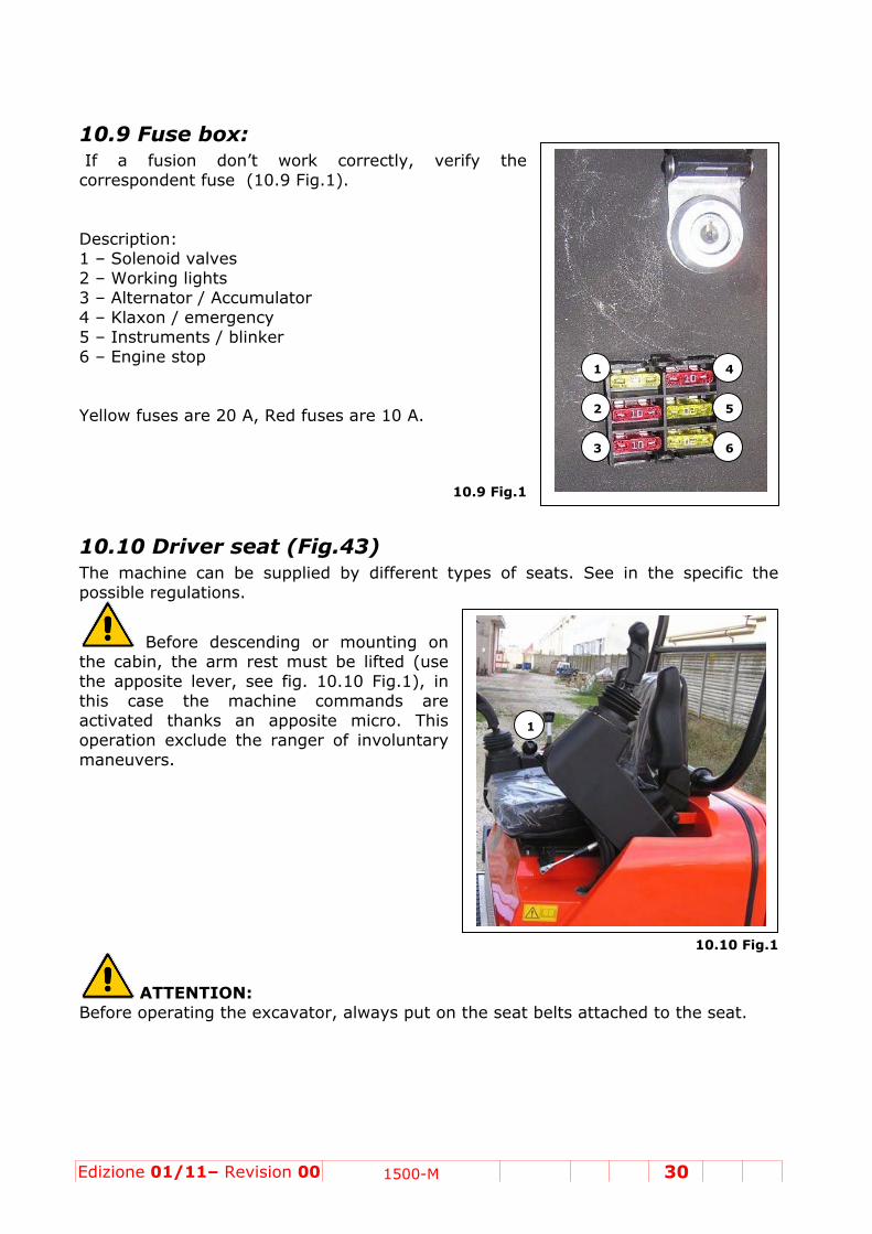
10.9 Fuse box: If a fusion don’t work correctly, verify the correspondent fuse (10.9 Fig.1). Description: 1 – Solenoid valves 2 – Working lights 3 – Alternator / Accumulator 4 – Klaxon / emergency 5 – Instruments / blinker 6 – Engine stop Yellow fuses are 20 A, Red fuses are 10 A.
10.9 Fig.1
10.10 Driver seat (Fig.43) The machine can be supplied by different types of seats. See in the specific the possible regulations.
Before descending or mounting on the cabin, the arm rest must be lifted (use the apposite lever, see fig. 10.10 Fig.1), in this case the machine commands are activated thanks an apposite micro. This operation exclude the ranger of involuntary maneuvers.
10.10 Fig.1
ATTENTION: Before operating the excavator, always put on the seat belts attached to the seat.
1
2
3
4
5
6

Edizione 01/11– Revision 00 31 1500-M
11. Engine bonnet opening and access to the internal parts of the excavator
11.1 Engine bonnet opening
The opening of the bonnets should be effectuated only for maintenance operations, switch off always the engine before the operation and lock the bonnets in opening position using the lock hook supplied. Position the excavator with the boom lowered to the ground and switch off the engine. Unlock (1 11.1 Fig. 1) using the key provided and press firmly, lifting the bonnet upwards. Then check that the safety rod (2 11.1 Fig. 1) locks in position.
Caution – The bonnet is very heavy to provide maximum protection for the mechanical and hydraulic parts, so be very careful when opening and closing it. To close the bonnet, raise it, pull firmly, and gently lower the bonnet into the original position.
11.1 Fig.1
1
2

Edizione 01/11– Revision 00 32 1500-M
11.2 Accessing internal parts of the excavator Position the machine with the boom lowered and the engine switched off. Release the cab safety lock (11.2 Fig.1). Position the hand pump lever as shown in the diagram (11.2 Fig. 2) and raise the cab slowly by means of the rod (1 – 11.2 Fig. 2). When the cab is fully raised, insert the stay (11.2 Fig. 3) in the slot andlower the cab slowly using the lever (2 - 11.2 Fig. 2) so that the stay is positioned correctly (11.2 Fig. 4).
VERY IMPORTANT Before carrying out any maintenance work, make sure the lever is in position(11.2 Fig. 4) and the stay is in the slot. Raise the bonnet for easy access when servicing all the hydraulic and mechanical components.
11.2 Fig. 1 11.2 Fig. 2
11.2 Fig. 3 11.2 Fig. 4
1
2

Edizione 01/11– Revision 00 33 1500-M
8
11.3 Closing the rollbar Effectuate the maneuvers of the last paragraph in the opposite sense.
NOTE: The EUROMACH company is not responsible for damage to objects and/or to persons if the warnings above are not followed.
To close the rollbar rotate the lever 2-11.2 Fig. 2, to the left. Control that the speed of closing were slow and that it cause any danger.

Edizione 01/11– Revision 00 34 1500-M
12. Filling the main tank with fuel CAUTION – Always switch off the excavator before filling with fuel. Never smoke while filling the tank and always keep well away from sources of heat. Unscrew the cap (12 Fig. 1) and fill the tank. Notes The tanks holds 30 lit. Only use fuels recommended .
12 Fig. 1

Edizione 01/11– Revision 00 35 1500-M
13. Starting up the excavator
Before starting up the excavator always check the level of the engine oil, hydraulic oil, reducer oil and the level of the cooling circuit.
13.1 Starting up • Insert the key into the switch and turn it towards the right to the ON position (13.1 Fig. 1).. The oil pressure control and battery charge lights should now come on. In this position the heating of the injectors takes place automatically. Wait until the yellow pilot light goes out. • Turn the key towards the right: the engine will start (13.1 Fig. 1). • As soon as the engine begins to turn over, release the key. If the engine does not start immediately, we advise against insisting with the key for more than 10 seconds.
13.1 Fig.1
NOTES: If the engine does not start, wait at least a minute between each attempt to prevent the battery from becoming flat after a few tries. When the engine is running, let it turn over at intermediate rpm for several minutes to permit good warming up: a guarantee of long life.
When the engine is running smoothly, the oil pressure and battery charge lights must be out. If the oil pressure light does not go out, stop the engine immediately and telephone a Service Centre immediately.
13.2 Operations at the end of work Before a break in the work, or at the end of the day the operator must park the excavator: the arm is lowered to the ground so that no accidental movements may take place (rest position). • With the accelerator lever, lower the rpm: we advise letting the engine idle for three minutes to stabilise the engine temperature before stopping. • Turn the ignition key to 0 and the engine will stop (13.1 Fig 1).

Edizione 0
14. Ma
14.1 Ge
Reremove tmaintenan
14.2 Da
ATFor enginGreasing• Grease t• Use only• Check tthe coolin• Check fo• Check th
01/11– Re
aintena
eneral i
emove alwthe currence.
aily ma
TENTIONne mainteg the pointsy the typehe oil leveg water leor any leahat the air
evision 00
ance
informa
ways the pent from
aintenan
N: enance se
defined in A greasesels in the evel. ks and topr filter is n
0 15
ation
pressure bthe batt
nce ope
ee the en
n 14.2 Figs recommeengine, re
p up the tanot blocked
500-M
before evetery befo
erations
nclosed ha
. 1, after eended (seeducer, ro
ank. d (pilot lig
ery machiore every
s
andbook.
each timee table).
otation, tow
ht on the
1
ne maintey electrica
.
the mach
w, and hy
dashboard
14.2 Fig.1
36
enance. Atal or me
hine is use
ydraulic cir
d).
ttention: echanical
d.
rcuit and

Edizione 01/11– Revision 00 37 1500-M
1
2
14.3 Periodical maintenance operations (every 200 hours of work) NOTE: - For maintenance of the engine see the handbook enclosed. - Perform the first programmed service (new machine) within the first 100 hours of work or the first month. - Have the successive programmed services performed at a Service Centre every 200 working hours or every month.
• Change the engine oil (see Engine handbook). • Change the engine oil filter (see enclosed engine handbook). • Change the fuel filter on the tank and clean the container. • Clean the air filter (14.3 Fig 1) change every 200 hours or once a year). • Check the tension of the fan belt. • Check if the fan belt has any visible damage. • Check that the water / oil radiator is always clean. 14.3 Fig.1
• Check that the pipes of the cooling circuit. • Check and if necessary refill the radiator (14.3 Fig. 2) with the special cooling liquid (water + anti-freeze).
14.3 Fig. 3
14.3 Fig. 2
• Check the engine rpm: when running the engine can reach a maximum of 2400 rpm; the minimum rpm for idling must be 750 rpm. • Check the working of the electrical system (pilot lights, lights, etc.). • Check that the screws in the motor bearings
and connected assemblies are tight. • Check the air filter blockage light. • Check the rotation reducer oil (1 -14.3 Fig. 3). • Check the driver reducer oil. • Check the hydraulic oil filter (2 - 14.3 Fig 3).
ATTENTION: Lubrication, maintenance and adjustments must never be performed with the engine running, except where specified in the Use and Maintenance
1
2

Edizione 01/11– Revision 00 38 1500-M
1
Manual. This is to avoid injury caused by accidental contact with the moving parts.
14.4 Periodical maintenance operations (every 1000 hours of work) Replacing the hydraulic oil This must be done at a Service Centre. Replacing the hydraulic oil filter
• Switch off the excavator engine. • Rest the boom on the ground as shown in
14.4 Fig. 1 • Tip up the cab and position the stay. • Unscrew the cap (1 - 14.4 Fig. 1) on the tank
slowly to allow the air out.
14.4 Fig. 1
ATTENTION: The oil tank is under pressure. Pay great attention to vent before unscrewing the filter closing cover. • Replacing the hydraulic oil filter screwing in anti-clockwise sense (2 - 14.3 Fig.
3) • After the replacing of the filter, pull the security rod and close the cabin blocking
the position. • The engine must rotate at the minimum for few minutes. Replacing the engine oil Refer to the engine handbook Replacing worn pin bushes Any pin bushes found to be worn must be replaced at a Service Centre. Replacing cooling water Cooling water must be replaced at a Service Centre. Replacing cylinder gaskets This must be done at a Service Centre. Checking reducer oil • Tip up the cab forwards • Unscrew the plug in the low part of reducer and empty completely the oil.
ATTENTION: Used oil must always be taken to a specialised waste disposal centre. • Close the plug (1 - 14.4 Fig. 2) • Refill through the upper tank and wait few minutes that the oil refill completely
the tank • Refill only to half tank

Edizione 01/11– Revision 00 39 1500-M
Changing the tow oil • Rotate the wheel as in figure 5. • Remove the two plugs (3 and 4 14.4 Fig. 2) and wait until the oil finishes draining. (For refilling see the paragraph 14.4 above).
14.4 Fig. 2
Changing the air filter (14.4 Fig.3) • Open the rear bonnet. • Unscrew the wing nut and dismount the closing cover. • Remove the filter and change it after cleaning the filter container with compressed air. • Close the cover and remount.
14.4 Fig.3

Edizione 01/11– Revision 00 40 1500-M
1
2
14.5 Information about maintenance operations Hydraulic oil top-up NOTE: Before performing this operation, lie the arm down and completely open the bucket, lower the machine completely so that all of the cylinder rods re-enter their cylinders (14.4 Fig. 1).
14.5 Fig. 1
• Check the oil level with the external tube
(14.4 Fig. 2) located on the right side • of the tank. The level should be around half
way up the tube. If this is not the • case, top-up by unscrewing the tank plug
(14.4 Fig.3). • Replace the plug when the operation is
finished.
14.5 Fig. 2 Checking the gearmotor oil • Open the rear bonnet. • Daily check the oil level, which must be about halfwayup the tank Fig. 14.5 Fig.3). • Refill with type B lubricant if necessary (see tableCap. 5.2).
14.5 Fig. 3

Edizione 01/11– Revision 00 41 1500-M
Topping-up the tow oil • Position the two Allen key screws of the reducer of the rear wheel as in figure 10 (90°). • Unscrew the right lateral screws ( 1 - 14.5 Fig.5) to check the level: if oil comes out the level is correct. If not, unscrew also the upper screw (2 – 14.5 Fig. 5) and top-up until oil comes out of the right hand screw. • When the operation is complete, close the two plugs.
14.5 Fig. 4 Topping-up the cooling liquid • Open the rear door.
ATTENTION: The cooling liquid must only be topped-up with the engine cold because the circuit is under pressure and the liquid could come out in a violent manner causing burns to the operator. • Unscrew the plug (14.5 Fig.5) on the radiator. • Top-up through until the liquid comes out of
the plug hole. • Re-close the radiator plug. • Close the rollbar and close the rear bonnet.
14.5 Fig. 5


![[XLS] · Web viewCENIK PALNAS-66001463 LED svít. 10W IP54 4200K PALNAS-66001470 LED svít. 10W IP54 3000K PALNAS-66001487 LED svít. 10W IP54 4200K PALNAS-66001494 LED svít. 10W](https://img.pdfslide.net/doc/110x75/5b4222137f8b9afb298b6ced/xls-web-viewcenik-palnas-66001463-led-svit-10w-ip54-4200k-palnas-66001470.jpg)