Embed Size (px)
Citation preview

ROTARY HOES UM-SERIES
UM1500 (UM60) – UM1800 (UM72)
OPERATOR'S MANUAL & PART’S INFORMATION

Congratulations for purchasing your new COSMO BULLY Rotary Hoe.
This Rotary Hoe has been designed and manufactured following all safety and quality requirements needed for a safe and satisfactory use over time.
A careful reading of this manual will allow you to understand this new piece of equipment and will provide you all the tools needed to use it safely.
Proper maintenance and knowledge of the safety rules of use will ensure the best performance and extend the life of the machine.
The Safety Alert Symbol used throughout this manual and on safety decals of the machine indicates the presence of potential hazard to the operator. When you see this symbol, be alert and carefully read the message that follows it.
The Safety Alert Symbol is used in conjunction with following Signal Words, according to the degree of possible injuries that may result operating the implement:
DANGER
Indicates an imminent hazardous situation that, if not avoided, will result in death or serious injury.
WARNING
Indicates a potentially hazardous situation that, if not avoided, could result in death or serious injury, and includes hazards that are exposed when guards are removed. It may also be used to alert against unsafe practices.
CAUTION
Indicates a potentially hazardous situation that, if not avoided, may result in minor or moderate injury. It may also be used to alert against unsafe practices.
IMPORTANT Indicates instructions or procedures that, if not observed, can cause damage to equipment or environment.
NOTE Indicates helpful information.
READ, UNDERSTAND, and FOLLOW the safety messages following the Safety Alert Symbol and Signal Words. Failure to comply with safety messages could result in serious bodily injury or death.

TO THE PURCHASER
This manual contains valuable information about COSMO BULLY ROTARY HOE. It
has been carefully prepared to give you helpful suggestions for operating, adjusting,
servicing repair parts.
Keep this manual in a convenient place for quick and easy reference. Study it
carefully. You have purchased a dependable and sturdy impleemnt, but only by proper
care and operation can you expect to get the service and long life designed and built into
it.
RIGHT-HAND AND LEFT-HAND sides are determined by watching from the tractor side.
Sometime in the future your implement may need new parts to replace those are
worn or broken. If so, go to nearest COSMO BULLY dealer and provide him the model and
part number.
Customer information
Name
Purchased from
Purchased date
Model No.
Serial No.

TABLE OF CONTENTS
1. ABOUT THIS MANUAL................................................................... 1
2. INTRODUCTION............................................................................... 1 2.1. IDENTIFICATION................................................................................................................................ 1
2.2. INTENDED USE.................................................................................................................................... 1
2.3. MAIN PARTS DESCRIPTION.......................................................................................................... 2
2.4. SPECIFICATION…………....................................................................................................................
3
3. SAFETY............................................................................................... 4 3.1. GENERAL SAFETY INSTRUCTIONS............................................................................................. 4
3.2. EQUIPMENT SAFETY INSTRUCTIONS....................................................................................... 5
3.3. OPERATING SAFETY INSTRUCTIONS........................................................................................ 6
3.4. TRANSPORTING SAFETY INSTRUCTIONS............................................................................... 7
3.5. MAINTENANCE SAFETY INSTRUCTIONS................................................................................. 8
3.6. STORAGE SAFETY INSTRUCTIONS.............................................................................................. 8
3.7. SAFETY LABELS.................................................................................................................................. 9
SAFETY LABELS POSITION AND DESCRIPTION...........................................................
9
4. SET-UP................................................................................................ 11 4.1. LOWER HITCHES POSITIONING.................................................................................................. 12
4.2. CONNECTING TO THE TRACTOR................................................................................................. 13
4.3. DRIVELINE INSTALLATION........................................................................................................... 14
DRIVELINE LENGTH CHECK................................................................................................. 15
4.4. TRACTOR-IMPLEMENT STABILITY............................................................................................
16
5. OPERATING....................................................................................... 16 5.1. START UP................................................................................................................................................ 16
5.2. OPERATING INSTRUCTIONS.......................................................................................................... 17
5.3. ADJUSTMENTS..................................................................................................................................... 18
LOWER LINKAGE ADJUSTMENT......................................................................................... 18
FRICTION CLUTCH ADJUSTMENT....................................................................................... 19
SKIDS ADJUSTMENT................................................................................................................. 19
TAIL FLAP ADJUSTMENT….................................................................................................... 20
5.4. STOPPING AND DISCONNECTION............................................................................................... 21
5.5. TRANSPORTING..................................................................................................................................
22
6. MAINTENANCE................................................................................. 22 6.1. BLADES REPLACEMENT.................................................................................................................. 23
6.2. GEARBOX LUBRICATION................................................................................................................. 24
6.3. SIDE CASE LUBRICATION................................................................................................................ 25
6.4. BEARING HOUSING LUBRICATION............................................................................................. 26
6.5. DRIVESHAFT MAINTENANCE....................................................................................................... 26

7. STORAGE...........................................................................................
27
8. SCRAPPING.......................................................................................
28
9. TROUBLESHOOTING......................................................................
28
10. TORQUE TABLE……………..............................................................
11. WARRANTY ………………………………………………………………….
12. SPARE PARTS...................................................................................
30
31
34
13. EC DECLARATION OF CONFORMITY......................................... 43

U-Series UM Rotary Hoe
1
1. ABOUT THIS MANUAL
The operator must read the manual for a correct understanding of the hazards that may present when operating the implement, as well as for obtain optimum performance from the machine.
The manual is part of the machine, it must be kept in good condition and remain with the machine even in case of resale, until its demolition. In case of loss or damage, request a new copy from the Manufacturer, Importer or your Dealer.
The information, descriptions and illustrations in this manual describes the state of the product at the time of its publication, and may not reflect the product in the future.
The Manufacturer reserve the right to make design improvements or changes in specifications without incurring in any obligation to install them on units previously sold.
Text, illustrations and drawings of this manual cannot be disclosed or transmitted, in whole or in part, to third parties without the written permission of the Manufacturer. All rights are reserved.
2. INTRODUCTION
2.1. IDENTIFICATION
Each Rotary Hoe has a plate for unique identification. Any request for assistance or information regarding the machine must be directed to the Manufacturer, Importer or Dealer always referring to the model and serial number as shown on the nameplate affixed to the machine:
2.2. INTENDED USE
The U-series are designed to be used uniquely for horticultural, agricultural, or commercial applications, to till soil for seedbed and planting preparation. They are designed to be mounted on tractors equipped with hydraulic lift and universal three point hitch that can support the implement weight, and driven by the power of the tractor through the PTO driveshaft. The tractors used to operate the U-series Rotary Hoes must have the following requirements:
Hitch Category: 3-point Cat. I standard
PTO: 540 RPM, 6-spline, 1 3/8 Z6
Horsepower: 35-50 HP
DANGER
Any use of the machine other than the intended use is non-intended use, and is to be considered as unauthorized and dangerous. The manufacturer assumes no liability for damage resulting from non-intended use.

U-Series UM Rotary Hoe
2
2.3. MAIN PARTS DESCRIPTION
1. Deck 2. Lower Linkage Point 3. Lower hitch pin 4. Upper hitch pin 5. Tower 6. Input shaft cover 7. Input shaft 8. Gearbox
9. Side transmission case 10. Tail Flap 11. Rotor 12. Blade 13. Support stand 14. Skid 15. PTO shaft
U-Series UM Rotary Hoe
3
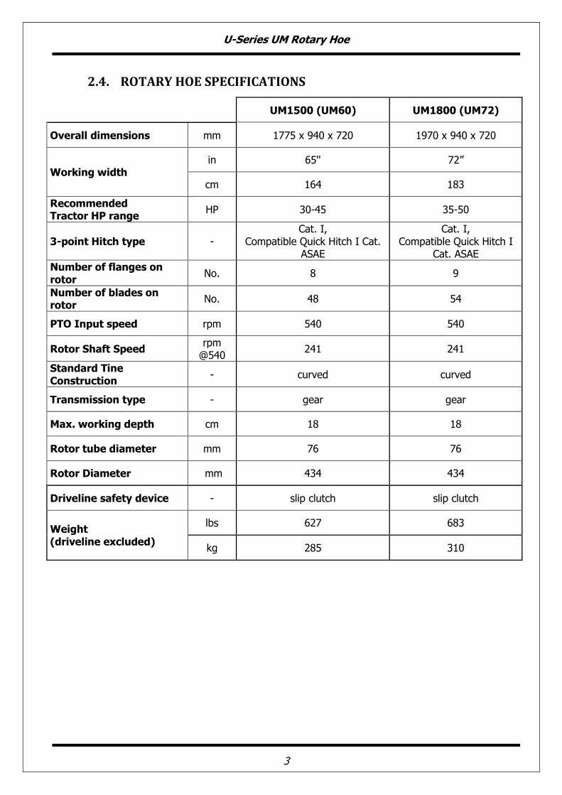
2.4. ROTARY HOE SPECIFICATIONS
UM1500 (UM60) UM1800 (UM72)
Overall dimensions mm 1775 x 940 x 720 1970 x 940 x 720
Working width in 65'' 72”
cm 164 183
Recommended Tractor HP range
HP 30-45 35-50
3-point Hitch type - Cat. I,
Compatible Quick Hitch I Cat. ASAE
Cat. I, Compatible Quick Hitch I
Cat. ASAE
Number of flanges on rotor
No. 8 9
Number of blades on rotor
No. 48 54
PTO Input speed rpm 540 540
Rotor Shaft Speed rpm @540
241 241
Standard Tine Construction
- curved curved
Transmission type - gear gear
Max. working depth cm 18 18
Rotor tube diameter mm 76 76
Rotor Diameter mm 434 434
Driveline safety device - slip clutch slip clutch
Weight (driveline excluded)
lbs 627 683
kg 285 310

U-Series UM Rotary Hoe
4
3. SAFETY
Safety is a primary concern in the design and manufacturing of our products. Unfortunately, our efforts to provide safe equipment can be wiped out by a single careless act of an operator.
In addition to the design and configuration of equipment, hazard control and accident prevention are dependent upon the awareness, concern, prudence and proper training of personnel involved in the operation, transport, maintenance and storage of equipment.
It has been said, “The best safety device is an informed careful operator.” We ask you to be that kind of operator.
The manufacturer assumes no liability for any damage resulting from not applying the behavioral rules indicated into the manual.
3.1 GENERAL SAFETY INSTRUCTION
DANGER
The machine must be used only by authorized and well trained operators. The operator must have read and understood the instructions of this manual. They must make adequate preparation for the proper use of the machine and in case of doubt about the use of the machine and/or the interpretation of this manual the operator must contact the Manufacturer or the Dealer.
WARNING
The manual must always remain with the machine. In case of loss or damage, request a new copy to the Manufacturer or your Dealer.
WARNING
Follow strictly the rules prescribed by the safety pictograms applied to the machine.
WARNING
Be sure that all safety pictograms are legible. If pictograms are worn, they must be replaced with others obtained from the Manufacturer, and placed in the position indicated by this manual.
DANGER
Before using the machine, make sure that all safety devices are installed and in good working conditions. In case of damages of shields, replace them immediately.
DANGER
Is absolutely forbidden to remove or alter safety devices.
DANGER
Before starting, and during operation of the implement make sure there are no people or animals in the operation area: the machine can project material from the back, with risks of serious injury or death.
DANGER
Pay maximum attention to avoid any accidental contact with rotating parts of the machine.
DANGER
During operation, adjustment, maintenance, repairing or transportation of the machine, the operator must always use appropriate Personal Protective Equipment (PPE).
U-Series UM Rotary Hoe
5
DANGER
Do not operate the implement while wearing loose fitting clothing that can give rise to entanglement in parts of the machine.
DANGER
Do not operate the implement when tired, not in good condition or under the influence of alcohol or drugs.
CAUTION
If the use of the machine is required at night or in conditions of reduced visibility, use the lighting system of the tractor and possibly an auxiliary lighting system.
3.2 EQUIPMENT SAFETY INSTRUCTIONS
WARNING
Use the implement for its intended purpose only. Improper use can damage the implement and cause serious injury to persons, animals, or death.
DANGER
The machine should be used by a single operator driving the tractor.
WARNING
Any unauthorized modification of the machine may cause problems in safety and relieves the Manufacturer from any liability for damages or injuries that may result to operators, third parties and objects.
WARNING
Before using the machine, familiarize yourself with its controls and its working capacity.
WARNING
Do not leave the implement unattended with tractor engine running.
WARNING
Do not operate implement on unstable (muddy or sandy) or rocky ground.
WARNING
Keep the machine clean from debris and foreign objects which may damage functioning or cause injury.
WARNING
Do not use the machine if the category of the connecting pins of the Rotary Hoe does not match that of the tractor hitch system.
WARNING
Do not use the machine with missing bolts, screws, pins or safety pins.
WARNING
Never use the machine to transport or lift people, animals or objects.

U-Series UM Rotary Hoe
6
WARNING
Make certain, by adding front ballast, that at least 20% of the total weight (tractor, implement and ballast) is on the front axle of the tractor, to ensure stability.
WARNING
Before engaging the tractor PTO, make sure the tractor PTO speed is set as required for this implement (540 rpm). Do not over speed PTO or machine breakage may result.
DANGER
Do not operate the implement if the driveshaft is damaged. The driveshaft could break during operation, causing serious injury or death. Remove the driveshaft and repair or replace it before continuing operation.
3.3 OPERATING SAFETY INSTRUCTIONS
WARNING
Before using the machine, be sure to have cleared the operating area from obstacles (stones, branches, debris, etc...). Mark all the obstacles that cannot be removed (e.g. by means flags).
DANGER
Never engage the tractor PTO in the presence of people close to the driveshaft. The body, hair or clothing of a person can get caught in rotating parts, causing serious injury or death.
DANGER
Before engaging the PTO and during all operations, make sure that no person or animal is in immediate area of action of the machine. Never use the Rotary Hoe if people are in his working area.
DANGER
It's absolutely forbidden to stand near an implement like this when parts are moving.
WARNING
The operator must operate implement (lifting/lowering) only from the driving seat of the tractor. Do not perform lifting maneuvers on side or behind the tractor.
WARNING
Before making changes in direction, turns or going in reverse, slightly lift the implement off the ground after disengaging the power take-off, to avoid damage to the machine.
DANGER
In presence of steep slopes (greater than 15 degrees) the action of this machine may cause instability of the tractor with a risk of tipping of which a consequence may be serious injury or death hazard. Consult the manual for the tractor to determine the maximum slope that the tractor is able to deal with.
DANGER
Always disengage the PTO before raising the implement and never engage the PTO with the implement raised. The machine might throw objects at high speed, causing serious injury or death.

U-Series UM Rotary Hoe
7
WARNING
Never leave the driver's seat when the tractor is turned on. Before leaving the tractor, lower the Rotary Hoe to the ground, disengage the PTO, insert the parking brake, stop engine and remove the key from the control panel.
DANGER
The PTO shields of tractor and implement side, the driveshaft shielding and the driveshaft retaining chains must be properly installed and in good condition, to avoid risk of entanglement with serious injury or death.
DANGER
Before engaging the PTO of the tractor, always make sure that the drive shaft is mounted in the correct direction, and that its clamping elements are properly connected both to tractor side and to Rotary Hoe side.
WARNING
Stop operating immediately if blades strike a foreign object. Repair all damage and make certain rotor and blades are in good condition before resuming operation.
WARNING
Always disengage the tractor PTO when the driveshaft exceed an angle of 10 degrees up or down while operating. An excessive angle with driveshaft rotating can break the driveshaft and cause flying projectiles.
CAUTION
Avoid clutch's overheating caused by too long or frequent slipping of the clutch, since it can damage the clutch components. Before checking slip clutch, make sure it has cooled. Clutch could be extremely hot and cause severe burn.
CAUTION
Prolonged use of the implement can cause overheating of the gearbox. Do not touch the gearbox during use and immediately after, it could be extremely hot and cause severe burn.
WARNING
All repairs to the implement must be performed by qualified and trained operators, with the tractor engine off, the PTO disengaged, the implement lowered to the ground or on security stands, the ignition key off and the parking brake set.
3.4 TRANSPORTING SAFETY INSTRUCTIONS
WARNING
Before transporting, determine the stopping characteristics of the tractor and implement.
WARNING
Transport only at speeds where you can maintain control of the equipment.
WARNING
When driving on roads, the implement must be in transport position adequately raised from the road surface, with tractor lifting hydraulics locked so that the Rotary Hoe cannot be lowered accidentally.

U-Series UM Rotary Hoe
8
DANGER
The implement may be wider than the tractor. Pay attention during transporting to persons, animals or obstacles exposed.
WARNING
When turning, use extreme care and reduce tractor speed.
WARNING
Do not operate the tractor with weak or faulty brakes or worn tires.
CAUTION
Always use tractor lighting system and auxiliary lighting system for an adequate warning to operators of other vehicles, especially when transporting at night or in conditions of reduced visibility.
DANGER
In the case of lifting this implement, make sure that any lifting device is suitable to perform the operation safely, and use only the lifting points prescribed on Rotary Hoe.
3.5 MAINTENANCE SAFETY INSTRUCTIONS
WARNING
All maintenance and repairing operations must be performed by qualified and trained operators, with the tractor engine off, the PTO disengaged, the Rotary Hoe lowered to the ground or on security stands, the ignition key off and the parking brake set.
WARNING
Perform repairs and replacements part should only be original spare parts provided by the manufacturer, importer or your dealer.
DANGER
Perform maintenance operations using appropriate Personal Protective Equipment (protective eye glasses, hard hat, hearing protection, safety shoes, overall and work gloves, filter mask).
CAUTION
Before any maintenance operation, make sure that the parts which become hot during use (friction clutch, gear box...) have cooled.
WARNING
Do not perform repairs that you do not know. Always follow the manual instructions and in case of doubt contact the Manufacturer or your dealer.
DANGER
Do not swallow fuels or lubricants. In case of accidental contact with eyes, rinse well with water and consult a doctor.
3.6 STORAGE SAFETY INSTRUCTIONS
WARNING
Never leave the tractor unattended with the implement in lifted position. Accidental operation of lifting lever or a hydraulic failure may cause sudden drop of unit which may result in injury/death.

U-Series UM Rotary Hoe
9
DANGER
Following operation, or before unhooking the implement, stop the tractor, set the brakes, disengage the PTO, lower the attached implement to the ground, shut off the engine, remove the ignition key and wait for all moving parts to stop.
WARNING
Make sure all parked machines are on a hard, level surface and engage all safety devices.
CAUTION
Place support blocks under implement as needed to prevent unit from tipping over onto a child and/or an adult. A implement that tips over can result in injury or death.
CAUTION
Store the unit in an area away from human activity.
3.7 SAFETY LABELS
The safety labels applied on the machine give fundamental information for using the machine safely.
Make sure safety labels are in good conditions. If pictograms are worn, they must be replaced with others obtained from the Manufacturer and placed in the position indicated by this manual.
Make sure the safety labels are legible. If necessary, wipe them by a cloth, with soap and water.
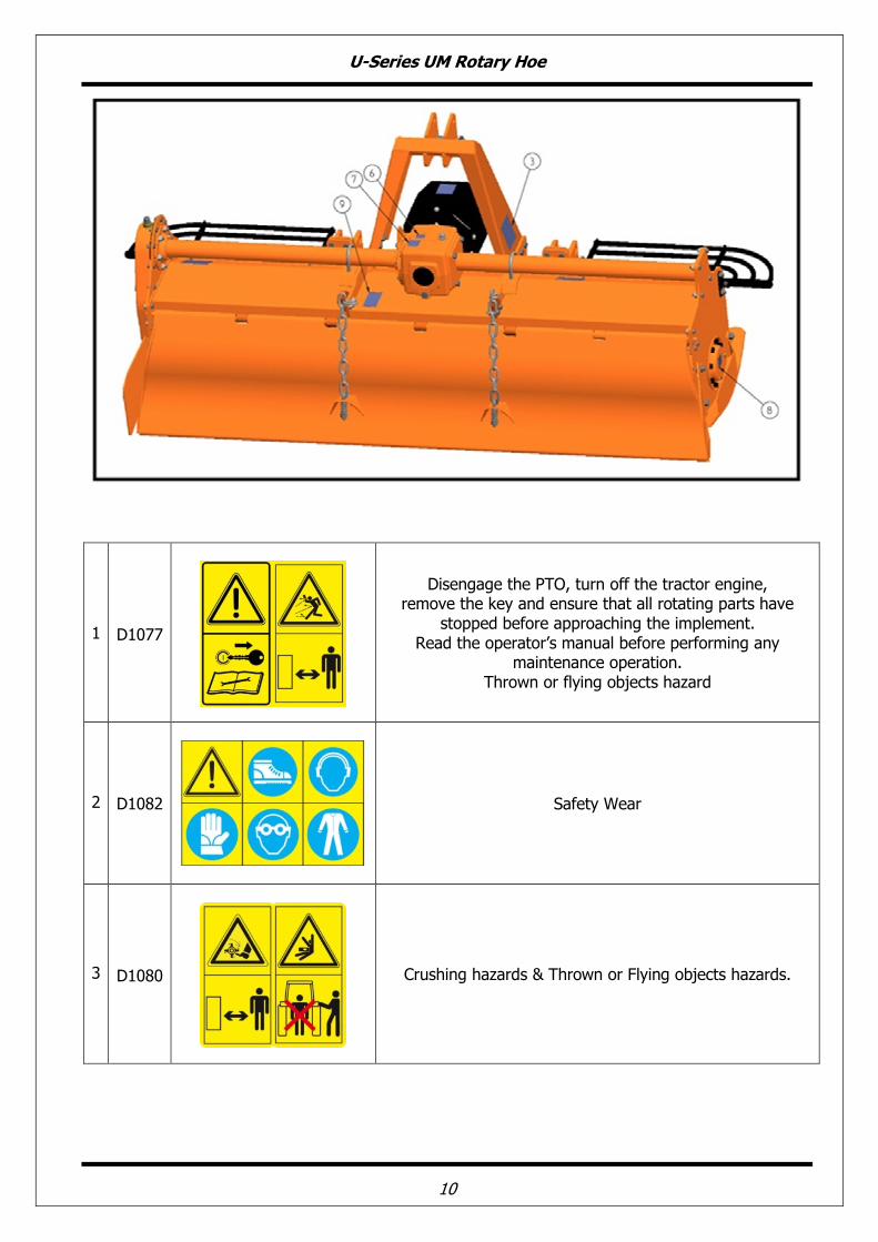
SAFETY LABELS POSITION AND DESCRIPTION
U-Series UM Rotary Hoe
10
1 D1077
Disengage the PTO, turn off the tractor engine, remove the key and ensure that all rotating parts have
stopped before approaching the implement. Read the operator’s manual before performing any
maintenance operation. Thrown or flying objects hazard
2 D1082
Safety Wear
3 D1080
Crushing hazards & Thrown or Flying objects hazards.

U-Series UM Rotary Hoe
11
4 D1081
Operate only with 540 rpm PTO.
5 D1079
Rotating Gears
6 D1007
Oil filling point
7 D1083
Lifting point
8 D1008
Grease filling point
9 D1078
Hand Hazard
4. SET UP
The implement is delivered fully assembled and equipped with a driveshaft with friction clutch (clutch discs) and related operating manual.
When the machine is delivered, check that there is no damage to the implement and driveshaft. In case of damage or missing parts immediately notify the manufacturer, importer or your dealer.

U-Series UM Rotary Hoe
12
4.1 . LOWER HITCHES POSITIONING
The UM-series Rotary Hoe is designed to be mounted on tractors equipped with:
• 3-point Hitch Category I (ISO 730 standard);
• Quick Hitch Category I (ASABE Standard).
The position of the lower hitches must be adjusted accordingly.
If the tractor is equipped with a 3-point Hitch Category I (ISO 730 standard), verify that the top link pin is on the lower hole (in the tower) and the lower links are also positioned in the lower holes (see figure) so that the distance between upper and lower pins is 18'' (460 mm approx), as required from the standard.
If this not occurs, proceed as follows:
• remove the pin from the upper hole of the tower, through the extraction of the pins and remove bushing provided for connecting the Quick Hitch. Reposition the pin through the lower hole. Replace the pins when finished. Store the bushing for possible future use;
• remove the U-bolt and the Lower Linkage Point from the square tube;
• invert the Lower Linkage Point orientation and reposition it on the square tube at distance of 13 7/16'' from the center of implement PTO. At the end of the operation the lower Linkage point should be positioned symmetrically respect to the implement input shaft at distance of 26 7/8'' (683 mm);
• re-tighten the U-bolt, referring to the tightening table of this manual.
• remove from lower pins the bushings provided for coupling with Quick Hitch, through the extraction of pins. Replace the pins when finished. Store the bushings for possible future use.
If the tractor is equipped with a Quick Hitch Category I (ASABE Standard), verify that the upper pin in the tower is oriented down, and that lower links are showing the pins oriented up (see figure), so that the distance between upper and the lower pins is 15'' (381 mm), as required from the standard.

U-Series UM Rotary Hoe
13
If not, then proceed as follows:
• remove the pin from the upper hole of the tower, through the extraction of the pins, and reposition the pin through the lower hole. Be sure the pin is provided with bushing for coupling with Quick Hitch. Replace the pins when finished;
• remove the U-bolts clamping the Lower Linkage Point to the square tube;
• invert the Lower Linkage Point orientation and reposition them on the square tube at distance of 13 7/16'' from the center of implement input shaft. At the end of the operation the Lower Linkage Point shall be positioned symmetrically respect to implement input shaft at distance of 26 7/8'' (683 mm);
• re-tighten the U-bolts, referring to the tightening table of this manual. Be sure the pins are provided with bushing for coupling with Quick Hitch.
NOTE
The upper hole of the tower provides the implement with the additional possibility of adaptation to tractors with 3-point hitch Category I.
4.2. CONNECTING TO THE TRACTOR
To connect the implement to the tractor the operator must do the following:
• drive the tractor in reverse, up to align the rear lifting arms to lower hitches of the implement in parking;
• set the tractor's parking brake, stop engine, remove the ignition key and get off the tractor;
• connect the lifting arms of the tractor to the lower hitches of the implement through the use of the pins and the relative safety split pins;
• connect the tractors rigid top link to implement tower;
• raise the implement until PTOs of tractor and machine are at the same height, then adjust the 3-point top link so that the front of the machine is leveled to the back (the axis of the Rotary
U-Series UM Rotary Hoe
14
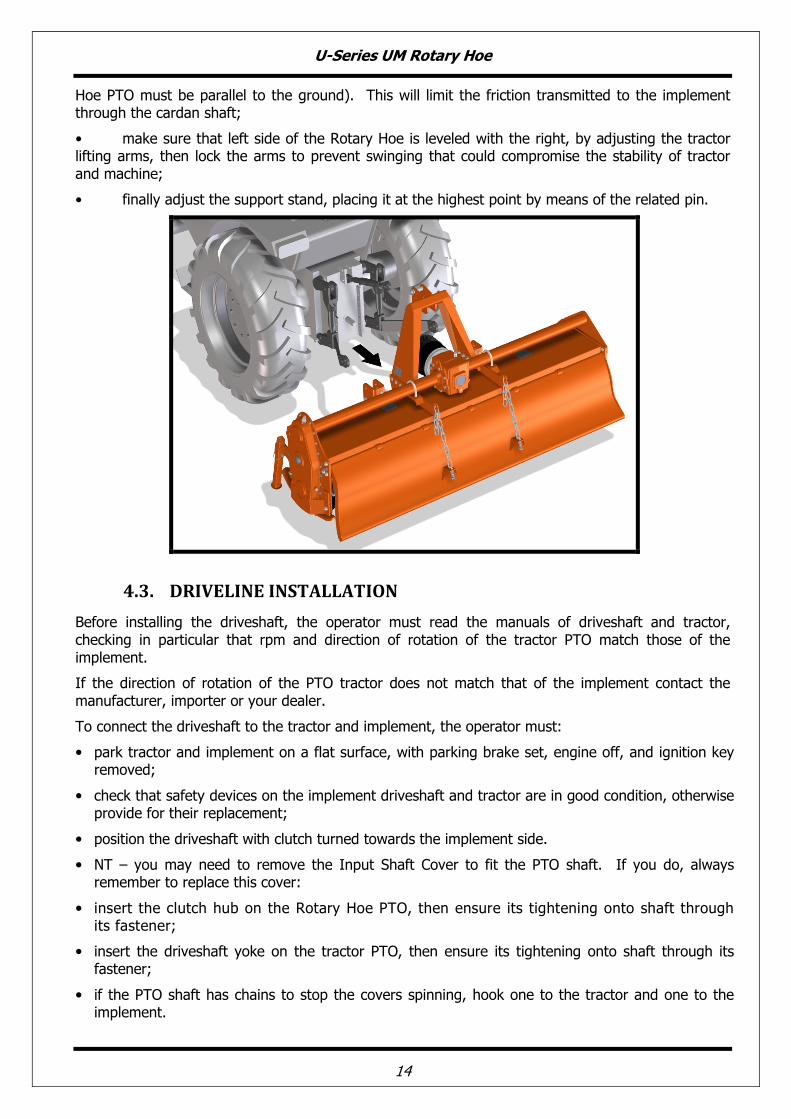
Hoe PTO must be parallel to the ground). This will limit the friction transmitted to the implement through the cardan shaft;
• make sure that left side of the Rotary Hoe is leveled with the right, by adjusting the tractor lifting arms, then lock the arms to prevent swinging that could compromise the stability of tractor and machine;
• finally adjust the support stand, placing it at the highest point by means of the related pin.
4.3. DRIVELINE INSTALLATION
Before installing the driveshaft, the operator must read the manuals of driveshaft and tractor, checking in particular that rpm and direction of rotation of the tractor PTO match those of the implement.
If the direction of rotation of the PTO tractor does not match that of the implement contact the manufacturer, importer or your dealer.
To connect the driveshaft to the tractor and implement, the operator must:
• park tractor and implement on a flat surface, with parking brake set, engine off, and ignition key removed;
• check that safety devices on the implement driveshaft and tractor are in good condition, otherwise provide for their replacement;
• position the driveshaft with clutch turned towards the implement side.
• NT – you may need to remove the Input Shaft Cover to fit the PTO shaft. If you do, always remember to replace this cover:
• insert the clutch hub on the Rotary Hoe PTO, then ensure its tightening onto shaft through its fastener;
• insert the driveshaft yoke on the tractor PTO, then ensure its tightening onto shaft through its fastener;
• if the PTO shaft has chains to stop the covers spinning, hook one to the tractor and one to the implement.

U-Series UM Rotary Hoe
15
DRIVELINE LENGTH CHECK
Before operating the implement ensure that the size of driveshaft is adequate. The driveshaft supplied with the machine comes in a standard length. Therefore it may need to be shortened depending on you tractor and implement.
The length of the driveshaft must be such to:
• avoid bottom out of the transmission tubes, when the driveshaft is in compressed position (when Rotary Hoe is raised up off the ground);
• ensure an overlapping of the transmission tubes enough to transmit the torque required, when the driveshaft is in max extension (when Rotary Hoe is in its lowest position in the ground).
When the driveshaft is at its minimum length (max compressed position), there must be at least a 2 cm of distance between the ends of each transmission tube and the yokes side.
When the driveshaft is at its maximum operational extension, there must be an overlap between the tubes profiles of 15 cm at least.
A driveshaft too long may cause structural damages to the tractor and machine. If the driveshaft is too long, it may be adapted by removing it and shortening the tubes according to the instructions provided by the manufacturer in its use and maintenance manual.
A driveshaft too short can cause disengage of the tubes during operation, with severe hazard for the operator and structural damage to the tractor and machine. If the driveshaft is too short, it must be replaced with a longer one. In this case contact the manufacturer or your dealer.

U-Series UM Rotary Hoe
16
IMPORTANT
• before operating the implement the first time, make sure that the driveshaft is lubricated in accordance with how indicated in the instruction booklet;
• before operating the implement the first time, and after long periods of inactivity, make sure that the driveline clutch has not seized. It may be necessary to ‘slip’ the clutch and reset due to possible oxidation of the components that may compromise the correct slipping during the usage (see also section "Maintenance");
• always engage the tractor PTO at low rpm to minimize the effect of the peak torque on the driveline and the machine.
4.4. TRACTOR-IMPLEMENT STABILITY
The weight of the machine modifies the stability of the system tractor-implement, resulting in loss of steering control and braking.
The front axle of the tractor should always loaded with at least 20% of the overall weight of the system tractor-implement.
CAUTION
Check the lifting capacity and stability of the tractor and, if necessary, applying the front ballast. To determine the appropriate characteristics of the ballast, refer to the manual of the tractor.
5. OPERATING
Before operate the implement, make sure you have read and understood the operating manuals of the implement, tractor and PTO shaft and followed what is described in the section "Set Up".
DANGER
During operation, adjustment, maintenance, repairing or transportation of the machine, the operator must always use appropriate Personal Protective Equipment (PPE).
Before starting work, ensure that all machine guards are in good conditions and fully functional.
During operation, the machine can throw material from the back: prevent people and animals to approach the operational area.
5.1. START UP
Before the start up and before each use, perform the following pre-operation inspections and service of the implement:
• check that the implement has no damaged functional parts and has all mechanical parts are good condition. Repair and / or replace the damaged parts;
• check that the implement has no missing parts (pins, safety pins, plugs oil ...). Restore the missing parts;
• check that all guards and safety devices have no damages and are properly positioned. Repair and / or replace the damaged shields, restore the correct position;
• verify that the PTO driveshaft is properly installed (see section: Connection of the drive shaft);
• check that the driveshaft clutch is in good condition, and that its components are not subject to "sticking" (see section: Maintenance / Driveline);
• check the presence of lubricant in all greasing points of the implement (driveshaft, supports...) (see sect. Maintenance / Driveline and Maintenance / Support rotor);

U-Series UM Rotary Hoe
17
• check for oil leaks from the gearbox or the transmission side cover. Identify the reason of loss, then repair and / or replace the damaged components;
• check the correct oil level in the gearbox and in transmission side box (see section maintenance);
• check that blades are not excessively worn and the relating hardware is correctly tightened (see sect. Maintenance);
• check that all hardware (nuts, bolts, etc.) are properly tightened. Refer to the tightening table in the manual for proper torque values;
• check that all safety decals are correctly positioned, in good condition and legible. Replace any damaged decals;
• check that there is no constraints that may prevent the movement of equipment. Remove any constraint.
Before the start up and before each use, make the following checks on the operating area you intend to operate:
• check that area is clear of foreign objects (rocks, branches or debris). Remove any obstacle and visibly highlight obstacles that cannot be removed (e.g. with flags);
• make sure that in the area you intend to operate there are no people or animals;
• make sure the soil to be worked is not too grassy, muddy, sandy or rocky.
WARNING
Before conducting the above inspections and service, make sure the tractor engine is off, all rotation parts are completely stopped and the tractor is in park with the parking brake engaged. Make sure the implement is resting on the ground or securely blocked up and the tractor lifting hydraulics locked.
Once all the checks above have been done, start tractor and the implement as follows:
• start the tractor and engage the tractor PTO at low rpm, making sure that the implement is NOT in the raised position but close to the ground, then increase speed engine until to 540 rpm;
• lower the implement on the ground and simultaneously start driving the tractor forward at low speed. Subsequently increase the ground speed depending on ground conditions;
• If the outside temperature is very cold , it's recommended to engage the PTO and have the implement operate at low speed (with the tractor stationary) to warm oil and lubricate parts;
• drive for a while operating the implement then stop the tractor to check the quality of the work performed. If you need to get off the tractor, lift the implement just out of the ground, reduce engine speed and disengage PTO, set the parking brake, stop engine and remove the ignition key;
If the working depth and/or soil texture are not as desired, correct them by adjusting the skids and/or the rear cover (see section Adjustments).
5.2. OPERATING INSTRUCTIONS
During operations:/ OPERATE ACCORDING TO FOLLOWING INTRUCTION
• always keep the tractor engine at a speed that delivers 540 rpm to the implement. Failure to do so will affect the performance to the implement;
• always keep a tractor speed suitable to conditions of the soil (from 2 to 10 km/h approx.). Reduce speed in the case of hard or stony soils;
• choose a driving pattern that provides the maximum pass length and minimizes turning;
• when working in the hills, always work up and down the hill. NEVER work across hills;

U-Series UM Rotary Hoe
18
• when changing directions or reversing, disengage the PTO and slightly lift the implement from the ground to avoid damage to the machine;
• periodically check for foreign objects wrapped around the rotor shaft and remove them, after disengaging PTO, turning off tractor engine, and removing ignition key;
• if the blades strike a foreign object, or in case of excessive friction clutch slippage, stop operating immediately, idle the engine speed and disengage the PTO. Wait for all rotating parts to come to a stop, then raise the implement and proceed to inspect damage, after stopped the tractor, set the parking brake, stopped engine and removed the ignition key. Repair any damage immediately, and make sure rotor and blades are in good condition before restarting operation;
• avoid friction clutch overheating. This is caused by operating in heavy conditions or incorrectly adjusted clutch. If you clutch overheats, in can damage clutch components which will them not operate correctly which may then result in damage to your implement.
Typical problems that may occur operating the implement are described into Troubleshooting section, together with their solutions.
5.3. ADJUSTMENTS
WARNING
All adjustment operations must be performed with the tractor engine off, the PTO disengaged, the
implement lowered to the ground or on security stands, the parking brake set and the ignition key
off.
LOWER LINKAGE ADJUSTMENT
It is possible to adjust the lower hitch position loosening the U-bolts 1 (see picture) and sliding the Lower Linkage Point (No.2) on the square tube. Tighten the U-bolts after making any adjustment required.
2
1

U-Series UM Rotary Hoe
19
FRICTION CLUTCH ADJUSTMENT
The PTO driveshaft and friction clutch are designed to transmit adequate power to the implement.
The clutch preserves the machine from overloads, through the slipping of friction discs, and limits the max torque transmissible to a calibrated value set at factory. It is recommended, therefore, to set the clutch and adjust regularly to avoid damages to the machine or to driveshaft.
Friction clutches are designed to be adjusted. If slipping is too frequent it means that the calibration is too low and the clutch needs to be adjusted (tightened).
In this case the tightening of the nuts will compress the springs which will increase the drive to the implement.
On the contrary, a loosening of the nuts will decrease the drive to the implement.
IMPORTANT
For details about clutch adjustment, refer to the user manual of the manufacturer of the driveshaft installed.
The manufacturer is not liable for damages resulting from a wrong modification of the clutch calibration.
NOTE
Excessive tightening of the springs can prevent the clutch from slipping and to protect the machine from overload.
Make sure that the height of all the compressed springs is equal to prevent the clutch malfunctioning.
SKIDS ADJUSTMENT
The working depth of the implement is determined by the position of the side skids: it may be increased by raising the skids, and decreased by lowered them. It's important that both skids are adjusted at the same height.
To adjust the working depth, perform the following steps:
• lift the machine, put it safely on security stands, then switch the tractor engine off, disengage PTO, set parking brake and off the ignition key;

U-Series UM Rotary Hoe
20
• loosen the in the front of the skid (bolt 1 - see picture);
• unscrew and remove the bolt on the rear of the skid (bolt 2 - see picture);
• adjust the height of the skid through the holes, as desired;
• reinstall the bolt 2 (refer to the tightening table of this manual for proper torque values);
tighten the bolt 1 (refer to the tightening table of this manual for proper torque value).
When finished, verify that both skids are at same level, and check if the front of the implement is leveled to the back, when lowered to the ground. Adjust with the 3-point top link if necessary.
TAIL FLAP ADJUSTMENT
The UM-Series Rotary Hoes are equipped with a Tail Flap with two (2) chain.
The position of the tail flap is adjustable by varying the number of chain links included between distance XY, which remain tensioned under the weight of the flap (i.e. links between the rear flap U-bolt 1 and the slot of the frame 2).
1
2 1 2
1
2

U-Series UM Rotary Hoe
21
• to raise the tail flap, reduce the number of chain links in tension. This operation, together with the increase of the tractor ground speed, allows to have a coarser soil texture;
• to lower the tail flap, increase the number of chain links in tension. This operation, together with the reduction of the ground speed will result in a finer soil texture.
WARNING
To avoid the risk of crushing or cutting of fingers, raise or lower the tail flap only from the lower edge, not from the sides.
5.4. STOPPING AND DISCONNECTION
To stop the implement at the end of a working session:
• bring the tractor to a complete stop;
• place the transmission in park or neutral;
• reduce the engine speed, then disengage the PTO;
• wait for stopping of all rotating parts;
• lower the implement to the ground;
• set the parking brake;
• shut down the engine and remove the key before exiting the tractor;
• do the cleaning and maintenance required to make the machine ready for later use (see Section Maintenance).
WARNING
Never leave the tractor unattended with the implement in the lifted position.
To disconnect the implement from the tractor (e.g. to make a change of implement):
• adjust the skids to their lowest position (see Section Adjustments);
• adjust the support stand to the lowest position, through the use of relative retaining pin;
• park the tractor on a dry and level surface;
• reduce the engine speed, then disengage PTO;
• wait for stopping of all rotating parts;
• lower the implement to the ground;
• set the parking brake;
• shut down the engine and remove the key before exiting the tractor;
• place safety blocks under implement to prevent unit from tipping over onto a child and/or an adult. An implement that tips over can result in injury or death;
• disconnect the driveline from the tractor PTO and rest it on the provided support of the implement;
• disconnect the top link and rear lifting arms of the tractor from the implement hitches;
• check the implement stability. If needed, place additional safety blocks;
• get on the tractor, start the engine and move away from the implement slowly;
• make sure the implement remains stored in a protected area, to prevent that unauthorized personnel can approach it.

U-Series UM Rotary Hoe
22
If you do not intend to use your implement for a long period of time, (e.g. at seasonal end), do cleaning and maintenance operations as specified in Sections MAINTENANCE and STORAGE.
5.5. TRASPORTING
To set the implement for transportation, perform the following steps:
• idle tractor engine, disengage tractor PTO, and wait for stopping of all rotating parts;
• lift the implement far enough off the ground to clear any object BUT not to a point where the PTO shaft comes in contact with the tractor or implement. A minimum gap of 2 cm should be leaved between the tubes and tractor and Rotary Hoe (see also Section Driveline installation);
• lock the tractor lifting hydraulics, turn off the engine, set the parking brake, remove ignition key and get off the tractor;
• adjust the support stand to the highest position, through the use of relative retaining pin, to prevent its possible damage during transport.
When driving on public roads, follow strictly all local laws and traffic regulations.
WARNING
When driving on public roads, reduce your speed, be aware of traffic around you and proceed in such a way that faster moving vehicles may pass you safely.
6. MAINTENANCE
Proper and regular maintenance ensures a long life of the implement, avoids failures and saves time and repair costs.
Periodic inspections and maintenance operations described in this section must be performed by operator in the times and terms prescribed. Failure to comply with maintenance prescriptions can compromise the functioning and duration of the machine, and consequently invalidate the warranty.
The frequency of maintenance indicated refers to normal conditions of use: it must be intensified in severe operating conditions (frequent stops and starts, prolonged winter season etc ...).
Repairs, maintenance and modifications other than those mentioned in this paragraph should NOT be performed without consulting the manufacturer or your dealer. Manufacturer, as the case, may give the authorization to proceed with the repair together with all necessary instructions.
Wrong or inappropriate repairs or maintenance may generate abnormal operating conditions, equipment damage and generate risks for the operator.
WARNING
For safety reasons, all maintenance operations must be performed with tractor PTO disengaged, implement stopped and completely lowered to the ground or onto support blocks, parking brake set, tractor engine shut off, and ignition key removed.
IMPORTANT
Respect the environment. Store or dispose of unused chemicals as specified by the chemical manufacturer.

U-Series UM Rotary Hoe
23
6.1. BLADE REPLACEMENT
Frequently check the wear condition of blades through visual inspection. The wear of blades is very variable depending on the type of soil.
Replacement of the blades is necessary when the operator notices increase of power absorption during operation or when the blade dimension is significantly reduced compared to the original.
The use of the machine with blades in bad condition compromises the quality of work.
Before perform replacement of the blades:
• idle tractor engine, set the parking brake, disengage tractor PTO, and wait for all moving parts to come to a complete stop;
• slightly raise the implement from the ground or place on safety blocks or mechanical stands;
• lock the height control lever of tractor’s hydraulics;
• turn off the tractor and remove the key.
To perform the replacement of blades:
• remove the two bolts and washers clamping the blade to the rotor flange, then remove the blade;
• position the new blade exactly where the worn blade was, then tighten the bolts, referring to the tightening table of this manual for proper torque values. Be sure to install the blade with cutting edge in front of the direction of rotation;
• repeat the same procedure for all the other blades.
At the end of the replacement, make sure the blades have the right helical arrangement, as shown in the figure:
Periodically check the tightness of screws and nuts, and tighten if necessary.
IMPORTANT
Remove and install one blade at a time to ensure blades are correctly oriented when installed.
Replace worn blades only with original parts.
CAUTION
Worn blades may be very sharp!

U-Series UM Rotary Hoe
24
1.1. GEARBOX LUBRICATION
Lubricant: SAE EP 80W90 gear oil
Check the oil level every 50 hours, making sure the oil mark left on the dipstick of the filling plug (top of gearbox) is located between the two reference marks (minimum and maximum).
If the oil is below the minimum, fill up to restore the correct level.
An oil change must be performed:
• after the first 50 working hours;
• each 500 working hours.
To carry out an oil change:
• place a tank under the oil drain plug (bottom of gearbox) ;
• unscrew the oil drain plug and drain oil completely into the tank;
• retighten the drain plug;
• unscrew the oil filling plug;
• fill with oil to achieve the correct level (between the two reference dipstick marks) ;
• retighten the filling plug;
• dispose the discharged oil into containers for used oil.
CAUTION
Before touching the gearbox wait until it has cooled.
IMPORTANT
Frequently check possible oil leaks from implement through visual inspection, and in case of leakage provide immediately proper maintenance.
Avoid oil leaks on the ground when restoring oil level or making oil change.
Filling Plug
drain Plug

U-Series UM Rotary Hoe
25
6.2. SIDE CASE LUBRICATION
Lubricant: SAE EP 80W90 gear oil
Check the oil level every 50 hours. Make sure it reaches the level plug on the transmission cover.
If the oil is below this level, fill up to restore the correct level.
The oil change must be performed every 500 working hours.
To make the oil change:
• remove the skid from the transmission side;
• place a tank under the oil level plug;
• unscrew the oil level plug and drain completely the oil into the tank;
• retighten the level plug;
• unscrew the oil filling plug (top of transmission cover);
• fill up to the correct level (until level plug);
• retighten the filling plug;
• replace the side skid;
• dispose the discharged oil into containers for used oil.
Filling Plug
Transmission
cover
Level plug

U-Series UM Rotary Hoe
26
6.3. BEARING HOUSING LUBRICATION
Lubricant: SAE multi-purpose lithium-type grease
Grease the rotor hub support every 8 working, through a suitable grease gun.
IMPORTANT
Make sure you clean the gear nipple before using grease gun.
Do not let excess grease collect on or around these parts especially when operating in sandy areas.
6.4. DRIVESHAFT MAINTENANCE
Lubricant: SAE multi-purpose lithium-type grease
Grease crosses, sliding parts of protective shielding and driveshaft transmission tubes.
Grease zerk

U-Series UM Rotary Hoe
27
IMPORTANT For details about maintenance and lubrication of the driveshaft, refer to the user manual of the driveshaft manufacturer.
Driveshaft clutch:
Exposure of the implement and driveshaft to environmental elements, as well as long period of inactivity, generally results in oxidation (rust) of some clutch components. This can result in a seized clutch which will offer no protection to the implement.
To avoid a seized clutch the operator must perform a short "run-in" of the clutch, as follows:
• take note of the height of the compressed springs;
• loosen the nuts of the compress the springs;
• connect the implement to the tractor (see section connecting to the tractor) ;
• connect the driveshaft (see section Driveline installation);
• start the tractor and engage PTO for few seconds. You should hear and/or see the clutch slip. If not, turn off the tractor, remove key and wait for all components are stopped before dismounting from tractor and loosen a little more;
• turn off the tractor, remove key and wait for all components are stopped before dismounting from tractor;
• tighten the nuts (gradually) to compress springs and re-establish torque (drive) to the implement as per instructions on page 18-19.
7. STORAGE
Before leaving the implement unused for a long time, it's necessary to perform following tasks to preserve the appearance and functionality of the machine, and to make easier the restart at later use:
• park the implement on a flat surface, in a dry place protected from exposition to the elements;
• thoroughly clean the machine, removing from the rotor all residues due to tillage, in order to avoid damage from grass and stagnant water;
• carefully inspect the machine, checking for worn and/or damaged parts. Perform immediately all repairs and/or replacements needed, in order to make the machine ready for restarting;
• in case of abrasion of painted surfaces, provide restoring the surface protection through touch-up paint to prevent rust;
• make sure the safety decals are in their original positions, intact and legible. When required, replace the decals immediately;
• lubricate properly all grease points, and restore the oil levels as indicated in the maintenance Section. Use protective oil to coat the exposed mechanical components and to protect them against rust.
If the implement driveshaft is equipped with a friction clutch, it is suggested to take note of the height of the compressed springs and loosen the bolts that compress the springs, to prevent the discs from "sticking" effect due to moisture, that may cause the clutch failure at restart of the activities (see also Driveshaft maintenance).
Before restart the operations, reset the clutch.

U-Series UM Rotary Hoe
28
8. SCRAPPING
In case of scrapping, the machine must be disposed in appropriate and authorized sites, according to local legislation.
Before scrapping, separate plastic parts from rubber parts, aluminum, steel, etc.
Recover and dispose any exhausted oils to authorized centers for oil collecting.
9. TROUBLESHOOTING
PROBLEM POSSIBLE CAUSE POSSIBLE SOLUTION
Gearbox/transmission case noise noticeable and constant
Low oil level. Worn gears.
Add oil to the gearbox/transmission case.
Replace gears
Intermittent
noise from implement
Loose blades. Gear tooth damaged.
Tighten blades hardware
Replace damaged gear
Noise and/or vibration from implement
Blades worn or damaged.
Bearings damaged.
The front of the implement is not leveled to the back.
Rotor damaged.
Hard soil.
Replace blades.
Replace bearings.
Adjust 3-point top link of tractor making implement PTO parallel to the ground.
Repair/replace rotor
Reduce ground speed
Driveline vibration Worn driveshaft .
Machine lifted too high. Debris wrapped on rotor.
Replace driveshaft.
Lower machine and readjust tractor lift stop. Remove debris.
Rotor stops turning Slip clutch slipping. Broken chain in chain box.
Reduce load to implement or adjust slip clutch.
Repair broken link.
Machine skip or leaves
crop residue
Badly worn blades.
Slip clutch slipping. Ground speed too fast for conditions.
Replace worn blades.
Adjust slip clutch or reduce load.
Reduce ground speed .
Smoke and/or hot smell from implement
Debris wrapped around in blades and/or rotor. Low oil level in gearbox.
Slip clutch slipping.
Remove debris.
Add oil
Reduce load to machine or adjust slip clutch.
Gearbox overheating Low oil level.
Hard soil.
Add oil.
Reduce ground speed.
Blades wear frequently Muddy or sandy soil. Reduce ground speed.

U-Series UM Rotary Hoe
29
Blades break frequently Stony soil. Reduce ground speed.
Oil leaking from gearbox/ transmission case
Gearbox/transmission case overfilled.
Loose filling/drain plug.
Damaged breather plug.
Damaged seals.
Drain to proper level.
Tighten filling/drain plug.
Replace breather plug.
Replace seals.
Implement depth insufficient
Implement is carried by tractor. Tractor has insufficient power. Skids need adjusting. Blades worn or bent. Blades incorrectly installed. Debris entangled in blades and/or rotor.
Lower tractor 3-point arms. Increase PTO speed Adjust skids. Replace blades. Install tines correctly. Clear rotor and/or blades
Soil texture too coarse Tail flap too high. PTO speed too slow. Ground speed too fast.
Lower tail flap. Increase PTO speed. Reduce ground speed.
Soil texture too fine Tail flap too low. Ground speed too slow.
Raise tail flap Increase ground speed.
Implement choking up with soil
Blades worn or bent. Blades incorrectly installed. Tail flap too low. Soil too wet.
Replace blades. Install tines correctly. Raise tail flap. Wait until soil dries.
Implement ‘skipping’ on ground or leaving crop residue
Blades incorrectly installed (wrong helical arrangement, cutting edge in wrong direction...)
Debris entangled in blades and/or rotor.
Ground speed too fast.
Soil too hard.
Install blades correctly (replace right helical arrangement, position cutting edge in front of rotation direction...)
Clear rotor and/or blades.
Reduce ground speed.
Reduce ground speed and make tilling in more steps.
Soil not uniform
Blades worn or damaged.
Skids not aligned.
left side not leveled with right side.
Replace blades.
Align skids.
Adjust tractor 3-point arms.
Tractor struggling (under too much load)
Excessive working depth.
Excessive PTO speed.
Lower skids.
Reduce PTO speed.

U-Series UM Rotary Hoe
30
10. TORQUE TABLE
Check frequently Rotary Hoe hardware to make sure that screws and bolts are tightened according to torque values listed in following table:
8.8 grade 10.9 grade
BOLT SIZE (METRIC)
N m Ft lb N m Ft lb
M6 11 8 15 11
M8 26 19 36 27
M10 52 39 72 53
M12 91 67 125 93
M14 145 105 200 150
M16 225 165 315 230
M18 310 230 405 300
M20 440 325 610 450

U-Series UM Rotary Hoe
31
11. WARRANTY
Tirth Agro Technology Pvt. Ltd. offer the following warranty to the purchaser of COSMO BULLY ROTARY HOE mentioned herein above subject to the conditions set out herein after provided the COSMO BULLY ROTARY HOE shall be in the possession of and used by such purchaser as from the date of delivery. Tirth Agro Technology Pvt. Ltd. warrants its products for a period of twevle (12) months against defective parts. This warranty shall not apply to implements or parts that have been subjected to negligence, of accident, or that have been altered or repaired or used with non-
genuine parts.
CONDITIONS If you wish to make a warranty claim you must first contact the supplier of your
goods to begin the claim process.
The following are the warranty terms and conditions for new goods sold in Australia by Farm
Implements P/L in conjunction with the manufacture Tirth Agro Technology Pvt. Ltd ( “We”,
“Our” or “Us”), both of 16 Cahill Street, Dandenong, Victoria, Australia, 3175.
1. To the extent that any goods or services supplied by Us are supplied to a ‘consumer’ as
defined in the Australian Consumer Law, We will comply with any applicable consumer
guarantees and the following statement will apply: “Our goods come with guarantees that
cannot be excluded under the Australian Consumer Law. You are entitled to a
replacement or refund for a major failure and for compensation for any other reasonably
foreseeable loss or damage. You are also entitled to have the goods repaired or replaced
if the goods fail to be of acceptable quality and the failure does not amount to a major
failure.”
2. ‘Australian Consumer Law’ means Schedule 2 of the Competition and Consumer Act 2010
(Cth).
3. The warranties provided in this document are in addition to any other rights or remedies
available to you under the law, and do not limit the consumer guarantees for ‘consumers’
under the Australian Consumer Law.
4. Goods presented for repair may be replaced by refurbished goods of the same type rather
than being repaired. Refurbished parts may be used to repair the goods.
5. Any warranty claim that is the result of operator abuse, neglect or unauthorised
modifications being made to the good will not be considered valid, subject to the
Australian Consumer Laws. The warranty does not cover costs of claiming under this
warranty; depreciation, damage, malfunction or failure caused by normal wear and tear;
lack of reasonable maintenance or improper servicing; failure to follow operating
instructions; misuse or lack of proper protection during storage. The expected normal
working conditions and maintenance requirements are outlined in the relevant operator’s
manual.
6. All new Implements are provided with a 12 month comprehensive warranty from the date of invoice against faulty workmanship or materials, under normal working conditions and service, as outlined in the relevant operational manual for the particular good. Your

U-Series UM Rotary Hoe
32
warranty for those goods will be considered void if any damage to the implement is caused by operator abuse, neglect, or if any unauthorised modifications have been made.
7. If you wish to make a warranty claim, you must immediately report the defect to the
supplier within the warranty or consumer guarantee claim period, including a written
statement of your claim, along with photos of the current condition of the goods by mail
(or if possible, email) to the address of the place from which you purchased the good.
You will be required to present valid proof of purchase, and at your expense promptly
provide the goods to the supplier immediately after notification of a service issue.
8. Please note that We require an assessment of the condition of the goods to be conducted
by either the supplier, Us or the manufacturer, as well as obtaining a history of use of the
good, before We can determine whether a consumer guarantee or manufacturer’s
warranty is applicable. We are not responsible for any transportation cost incurred in the
repair or replacement of parts not covered by the warranty.
9. To the maximum extent permitted by law, and except in circumstances where the
consumer guarantee provisions under the Australian Consumer Law apply and are
inconsistent with the following, Our liability for the supply of the goods is limited, at Our
discretion, to 1) replacement of the goods or the supply of equivalent goods; 2) repair of
the goods; 3) payment of the cost of replacing the goods or acquiring equivalent goods;
or 4) payment of the cost of having the goods repaired.
10. You acknowledge that use of the goods is inherently dangerous and agree that to the
maximum extent permitted by law, We are not liable in any event for consequential loss,
damage or injury, including loss of crops, loss of profits, or personal injury or death
howsoever caused.
11. Farm Implements Dealers have no authority to make any representation, promise or
admission on behalf of Us or to modify the terms or limitations of these Warranty
Conditions in any way. Nothing in these Warranty Conditions constitutes a partnership
between Us and any Farm Implements Dealer, or constitutes any Authorised Dealer as an
agent or employee of Ours for any purpose at all. Our Dealers have no authority or
power to bind Us, to contract in the name of Farm Implements P/L or to create a liability
against Us in any way or for any purpose at all, including but not limited to
representations regarding performance or fitness for any purpose of the goods.
If you have specific queries regarding the warranties or consumer guarantees provided by Farm Implements P/L in conjunction with the manufacture Tirth Agro Technology Pvt. Ltd please send details of your claim to Our attention at 16 Cahill Street, Dandenong, Victoria, Australia, 3175, or via email at [email protected] or phone 03-9706-5166.
THIS CONTRACT WILL BE INEFFECTIVE AND INOPERATIVE IF:
a. The COSMO BULLY ROTARY HOE has not been delivered, assembled, started and put into operation by the company or it’s Authorized Representative.
b. The warranty card has not been returned within 30 days of date of purchase. c. The COSMO BULLY ROTARY HOE parts thereof is subjected to neglect, fire, flood or
other acts of God or if in the company’s opinion any damage has caused to the COSMO BULLY ROTARY HOE in transportation.

U-Series UM Rotary Hoe
33
d. The original numbers are removed, obliterated or altered from the unit. e. Any attempt is made to have the repairs executed by a person or persons, other than
the company or its authorized representative. f. Any defect is not informed immediately to the company or its authorized
representative, any alteration in warranty card is made. g. Any change in the location of the COSMO BULLY ROTARY HOE or in its ownership
during the warranty period must be intimated in writing to the company or its Authorized Representative ten days before the change. Failure to do so will absolve the company from the obligation under this warranty.
h. Damage to the COSMO BULLY ROTARY ROTARY HOE or any part thereof caused, during shifting or transportation is not covered by this warranty.
i. This warranty is given in lieu of all other guarantees and condition expressed or implied by law or by any person purporting to act on behalf of the COMPANY and excludes every condition, warranty or guarantee not herein expressly set out.
NT – Parts/materials that are not covered by the warranty are as follows: 1. Blade 2. Universal Joint Cross 3. Paint 4. Bearing 5. Rubber Parts 6. Gaskets 7. Fasteners
� WHEN THE WARRANTY BECOMES VOID Besides the cases specified in the supply agreement, the warranty shall in any case become void:
• Should there have been a maneuvering error, use of an inadequate safety bolt on the cardan shaft torque limiter or when the cardan shaft clutch has been damaged through improper maintenance.
• When the implement has been used beyond the specified power limit as given in the technical data chart.
• When following repairs made by the customer without authorization from the manufacturer or owing to instillation of spurious spare parts, the machine is subjected to variations and the damage can be ascribed to these variations.
• Whenever the user or anyone else on his behalf applies equipment to the machine that has not been expressly approved by the manufacturer.
• When the user failed to comply with the instructions in this manual book.

U-Series UM Rotary Hoe
34
12. SPARE PARTS
All repairs and replacements on the machine must be performed only by using original spare parts, which must be obtained / provided from the manufacturer or your dealer.
This section contains the information needed to identify the parts of U-series Rotary Hoe that may be ordered to manufacturer.
When request spare parts to manufacturer, always give following indications:
• type of machine;
• Rotary Hoe serial number;
• description and p/number of the spare parts;
• quantities.
NOTE
For identification of p/numbers and description of safety decals refer to the Section Safety labels.
For identification of p/numbers and description of PTO driveline parts, refer to the manual of the driveshaft manufacturer.
8. The Manufacturer reserves the right to substitute a required part with an equivalent part, if applicable.

U-Series UM Rotary Hoe
35
UM SERIES ROTARY HOE SPARE PARTS TABLE

U-Series UM Rotary Hoe
36
� UM1800 (UM72) ROTARY HOE SPARE PARTS LIST
ITEM P/NUMBER QTY. PART NAME
1 4655 27 BLADE L - TYPE LH (70x6) (REG L)
2 4656 27 BLADE L - TYPE RH (70x6) (REG L)
3 1214 1 HINCH PIN TOP CAT-I (DIA- 19 X 126)
4 1379 27 BLADE C- TYPE RH (REG) (70 X 6)
5 1380 27 BLADE C- TYPE LH (REG) (70 X 6)
6 1002 3 CIRCLIP INTERNAL 72mm
7 1003 1 BEARING 30207
8 1022 2 BEARING 30208
9 10181 10 HEX BOLT M10 X 1.50 X 30
10 6072 2 HEX BOLT M8 X 1.25 X 30
11 1073 2 BEARING 6309 LU
12 1074 2 INTERNAL CIRCLIP 6309(100MM)
13 10180 12 HEX BOLT M10 X 1.50 X 25
14 6068 4 HEX BOLT M10 X 1.50 X 35
15 1209 30 M12X1.75 NYLOCK NUT
16 1218 3 LINCH PIN
17 1253 1 1/8 BSP GREASE NIPPLE 7.5MM
18 1298 22 M10X1.5 NYLOCK NUT
19 1301 108 M12X1.75 HEX NUT
20 1303 20 SPRING WASHER 8mm
21 1304 4 SPRING WASHER 10mm
22 1306 120 SPRING WASHER 12mm
23 10194 120 HEX BOLT M12 X 1.75 X 35
24 10192 16 HEX BOLT M12 X 1.75 X 30
25 2089 1 EXTERNAL CIRCLIP 45MM
26 10195 8 HEX BOLT M12 X 1.75 X 40
27 8027 1 EXTERNAL CIRCLIP 40MM
28 8040 18 HEX BOLT M8 X 1.25 X 20
29 8064 8 PLAIN WASHER 8mm
30 8126 2 PLAIN WASHER 12mm
31 8169 8 HEX BOLT M12 X 1.75 X 25
32 8171 8 HEX BOLT M8 X 1.25 X 25
33 8181 20 HEX NUT M8 X 1.25
34 1216 2 HITCH PIN BOTTOM CAT-I (DIA-22 X 129)
35 1426 1 SIMS (DIA.50X42)(0.2MM)
36 1449 2 NYLOCK NUT (M35X1.5MM)
37 10143 1 BEARING 6207
38 14004 2 J-BOLT M12 x 1.75 x 24 x 87.5 x 25TL
39 14005 2 U-BOLT SPRING (U-SERIES)
40 14016 2 BUSH (DIA. 36.5 X 22.5 X 50 L)
41 14038 1 BUSH (DIA. 19.5 X 31.5 X 52 L)
42 14049 1 CROWN WASHER (U-SERIES)

U-Series UM Rotary Hoe
37
43 14058 1 CSK BOLT M10 X 1.5 X 25
44 14065 1 NYLOCK NUT M24 x 2
45 14073 2 LIFTING CHAIN TB
46 4657 1 SIDE STAND TOP BUSH (BAN)
47 10179 1 3/8" BSPT PLUG WITH SQ. HEAD
48 14109 1 GEAR 36 TEETH (U/M-SERIES)
49 14110 1 GEAR 26 TEETH (U/M-SERIES)
50 14111 1 GEAR 17 TEETH (U/M-SERIES)
51 14112 1 PINION 15 TEETH (U/M-SERIES)
52 14113 1 CROWN 22 TEETH (U/M-SERIES)
53 14114 2 RD SHAFT HOUSING GEAR SIDE (U/M-SERIES)
54 14115 1 RD SHAFT GEAR SIDE (U/M-SERIES)
55 14117 1 STUB AXLE SHAFT SD SIDE (U/M-SERIES)
56 14118 1 GEAR BOX (U/M-SERIES)
57 14130 2 DUST COVER (U/M-SERIES)
58 14126 1 AIR BREATHER 1/2" BSP
59 14127 2 BEARING 30306
60 10229 1 OIL SEAL 35 x 72 x 8
61 14121 1 OIL SEAL 40 x 62 x 7
62 14122 2 OIL SEAL 55 x 90 x 10
63 14131 2 O RING 30 x 3.50
64 14133 1 HOU FLANGE BIG GASKET (U/M-SERIES) 0.8MM
65 14134 1 HOUSING FLANGE SMALL GASKET (U/M-SERIES)
66 14135 3 R D HOUSING GASKET (U/M-SERIES)
67 14136 1 CHAIN COVER GASKET (U/M-SERIES)
68 14080 1 HULL COMP 1.8M (U/M-SERIES)
69 14081 2 JACK SHAFT HOUSING U CLAMP (U/M-SERIES)
70 14082 1 JACK SHAFT 946MM (U/M-SERIES)
71 14083 1 J/S HOUSING COMP (J-944) (U/M-SERIES)
72 14084 1 FULL HOUSING COMP (J-944) (U/M-1.8M/540)
73 14085 1 GEAR BOX LIFTING HOOK (U/M-SERIES)
74 14087 1 TOWER COMP (U/M-SERIES)
75 14088 1 TRAILING BOARD ROD 1.8M(U/M-SERIES)
76 14089 1 TRAILING BOARD COMP 1.8M (U/M-SERIES)
77 14090 1 DEPTH SKID COMP RH (U/M-SERIES)
78 14091 1 DEPTH SKID COMP LH (U/M-SERIES)
79 14092 1 ROTOR COMP 1.8M (U/M-SERIES)
80 14094 1 R D PLATE GD COMP (U/M-SERIES)
81 14096 1 R D SHAFT MIDDLE (U/M-SERIES)
82 14098 1 SPACER DIA-52 x 40.15 x 5.5 MM
83 14099 1 SPACER DIA-52 x 40.15 x 7 MM
84 14100 1 S D PLATE (U/M-SERIES)
85 14103 1 CHAIN COVER GD COMP (U/M-SERIES)
86 14104 1 SIDE STAND OUTER COMP (U/M-SERIES)
87 14105 1 SIDE STAND INNER COMP (U/M-SERIES)
88 14106 1 INPUT SHAFT 540 (U/M-SERIES)
U-Series UM Rotary Hoe
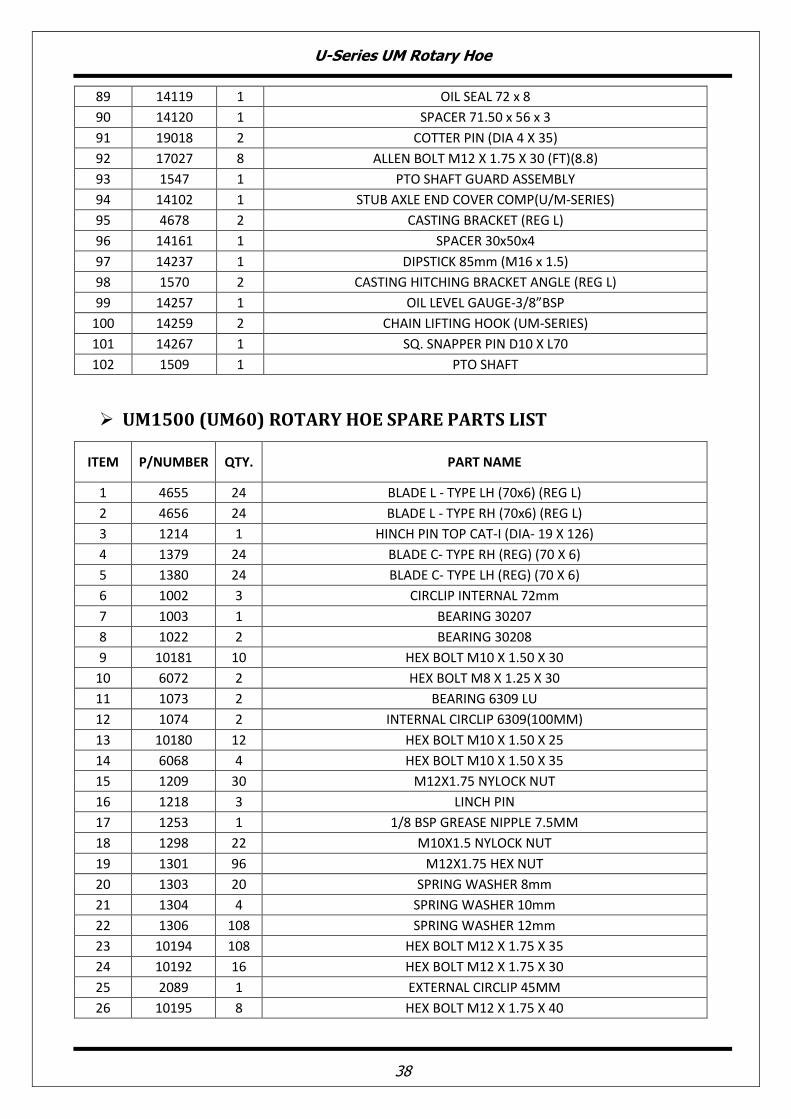
38
89 14119 1 OIL SEAL 72 x 8
90 14120 1 SPACER 71.50 x 56 x 3
91 19018 2 COTTER PIN (DIA 4 X 35)
92 17027 8 ALLEN BOLT M12 X 1.75 X 30 (FT)(8.8)
93 1547 1 PTO SHAFT GUARD ASSEMBLY
94 14102 1 STUB AXLE END COVER COMP(U/M-SERIES)
95 4678 2 CASTING BRACKET (REG L)
96 14161 1 SPACER 30x50x4
97 14237 1 DIPSTICK 85mm (M16 x 1.5)
98 1570 2 CASTING HITCHING BRACKET ANGLE (REG L)
99 14257 1 OIL LEVEL GAUGE-3/8”BSP
100 14259 2 CHAIN LIFTING HOOK (UM-SERIES)
101 14267 1 SQ. SNAPPER PIN D10 X L70
102 1509 1 PTO SHAFT
� UM1500 (UM60) ROTARY HOE SPARE PARTS LIST
ITEM P/NUMBER QTY. PART NAME
1 4655 24 BLADE L - TYPE LH (70x6) (REG L)
2 4656 24 BLADE L - TYPE RH (70x6) (REG L)
3 1214 1 HINCH PIN TOP CAT-I (DIA- 19 X 126)
4 1379 24 BLADE C- TYPE RH (REG) (70 X 6)
5 1380 24 BLADE C- TYPE LH (REG) (70 X 6)
6 1002 3 CIRCLIP INTERNAL 72mm
7 1003 1 BEARING 30207
8 1022 2 BEARING 30208
9 10181 10 HEX BOLT M10 X 1.50 X 30
10 6072 2 HEX BOLT M8 X 1.25 X 30
11 1073 2 BEARING 6309 LU
12 1074 2 INTERNAL CIRCLIP 6309(100MM)
13 10180 12 HEX BOLT M10 X 1.50 X 25
14 6068 4 HEX BOLT M10 X 1.50 X 35
15 1209 30 M12X1.75 NYLOCK NUT
16 1218 3 LINCH PIN
17 1253 1 1/8 BSP GREASE NIPPLE 7.5MM
18 1298 22 M10X1.5 NYLOCK NUT
19 1301 96 M12X1.75 HEX NUT
20 1303 20 SPRING WASHER 8mm
21 1304 4 SPRING WASHER 10mm
22 1306 108 SPRING WASHER 12mm
23 10194 108 HEX BOLT M12 X 1.75 X 35
24 10192 16 HEX BOLT M12 X 1.75 X 30
25 2089 1 EXTERNAL CIRCLIP 45MM
26 10195 8 HEX BOLT M12 X 1.75 X 40

U-Series UM Rotary Hoe
39
27 8027 1 EXTERNAL CIRCLIP 40MM
28 8040 18 HEX BOLT M8 X 1.25 X 20
29 8064 8 PLAIN WASHER 8mm
30 8126 2 PLAIN WASHER 12mm
31 8169 8 HEX BOLT M12 X 1.75 X 25
32 8171 8 HEX BOLT M8 X 1.25 X 25
33 8181 20 HEX NUT M8 X 1.25
34 1216 2 HITCH PIN BOTTOM CAT-I (DIA-22 X 129)
35 1426 1 SIMS (DIA.50X42)(0.2MM)
36 1449 2 NYLOCK NUT (M35X1.5MM)
37 10143 1 BEARING 6207
38 14004 2 J-BOLT M12 x 1.75 x 24 x 87.5 x 25TL
39 14005 2 U-BOLT SPRING (U-SERIES)
40 14016 2 BUSH (DIA. 36.5 X 22.5 X 50 L)
41 14038 1 BUSH (DIA. 19.5 X 31.5 X 52 L)
42 14049 1 CROWN WASHER (U-SERIES)
43 14058 1 CSK BOLT M10 X 1.5 X 25
44 14065 1 NYLOCK NUT M24 x 2
45 14073 2 LIFTING CHAIN TB
46 4657 1 SIDE STAND TOP BUSH (BAN)
47 10179 1 3/8" BSPT PLUG WITH SQ. HEAD
48 14109 1 GEAR 36 TEETH (U/M-SERIES)
49 14110 1 GEAR 26 TEETH (U/M-SERIES)
50 14111 1 GEAR 17 TEETH (U/M-SERIES)
51 14112 1 PINION 15 TEETH (U/M-SERIES)
52 14113 1 CROWN 22 TEETH (U/M-SERIES)
53 14114 2 RD SHAFT HOUSING GEAR SIDE (U/M-SERIES)
54 14115 1 RD SHAFT GEAR SIDE (U/M-SERIES)
55 14117 1 STUB AXLE SHAFT SD SIDE (U/M-SERIES)
56 14118 1 GEAR BOX (U/M-SERIES)
57 14130 2 DUST COVER (U/M-SERIES)
58 14126 1 AIR BREATHER 1/2" BSP
59 14127 2 BEARING 30306
60 10229 1 OIL SEAL 35 x 72 x 8
61 14121 1 OIL SEAL 40 x 62 x 7
62 14122 2 OIL SEAL 55 x 90 x 10
63 14131 2 O RING 30 x 3.50
64 14133 1 HOU FLANGE BIG GASKET (U/M-SERIES) 0.8MM
65 14134 1 HOUSING FLANGE SMALL GASKET (U/M-SERIES)
66 14135 3 R D HOUSING GASKET (U/M-SERIES)
67 14136 1 CHAIN COVER GASKET (U/M-SERIES)
68 14242 1 HULL COMP 1.5M (U/M-SERIES)
69 14081 2 JACK SHAFT HOUSING U CLAMP (U/M-SERIES)
70 14240 1 JACK SHAFT 848mm (U/M-SERIES)
71 14244 1 J/S HOUSING COMP (J-848) (U/M-SERIES)
72 14245 1 FULL HOUSING COMP.(J-848) (U/M-1.5M/540)

U-Series UM Rotary Hoe
40
73 14085 1 GEAR BOX LIFTING HOOK (U/M-SERIES)
74 14087 1 TOWER COMP (U/M-SERIES)
75 14241 1 TRAILING BOARD ROD 1.5M (U/M-SERIES)
76 14247 1 TRAILING BOARD COMP 1.5M (U/M-SERIES)
77 14090 1 DEPTH SKID COMP RH (U/M-SERIES)
78 14091 1 DEPTH SKID COMP LH (U/M-SERIES)
79 14246 1 ROTOR COMP 1.5M (U/M-SERIES)
80 14094 1 R D PLATE GD COMP (U/M-SERIES)
81 14096 1 R D SHAFT MIDDLE (U/M-SERIES)
82 14098 1 SPACER DIA-52 x 40.15 x 5.5 MM
83 14099 1 SPACER DIA-52 x 40.15 x 7 MM
84 14100 1 S D PLATE (U/M-SERIES)
85 14103 1 CHAIN COVER GD COMP (U/M-SERIES)
86 14104 1 SIDE STAND OUTER COMP (U/M-SERIES)
87 14105 1 SIDE STAND INNER COMP (U/M-SERIES)
88 14106 1 INPUT SHAFT 540 (U/M-SERIES)
89 14119 1 OIL SEAL 72 x 8
90 14120 1 SPACER 71.50 x 56 x 3
91 19018 2 COTTER PIN (DIA 4 X 35)
92 17027 8 ALLEN BOLT M12 X 1.75 X 30 (FT)(8.8)
93 1547 1 PTO SHAFT GUARD ASSEMBLY
94 14102 1 STUB AXLE END COVER COMP(U/M-SERIES)
95 4678 2 CASTING BRACKET (REG L)
96 14161 1 SPACER 30x50x4
97 14237 1 DIPSTICK 85mm (M16 x 1.5)
98 1570 2 CASTING HITCHING BRACKET ANGLE (REG L)
99 14257 1 OIL LEVEL GAUGE-3/8”BSP
100 14259 2 CHAIN LIFTING HOOK (UM-SERIES)
101 14267 1 SQ. SNAPPER PIN D10 X L70
102 1509 1 PTO SHAFT
U-Series UM Rotary Hoe
41
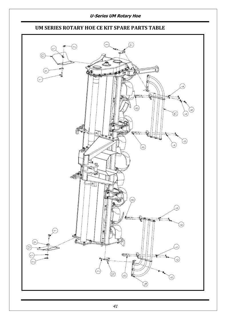
UM SERIES ROTARY HOE CE KIT SPARE PARTS TABLE
U-Series UM Rotary Hoe
42
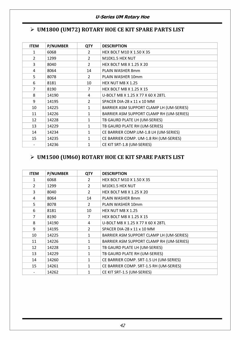
� UM1800 (UM72) ROTARY HOE CE KIT SPARE PARTS LIST
ITEM P/NUMBER QTY DESCRIPTION
1 6068 2 HEX BOLT M10 X 1.50 X 35
2 1299 2 M10X1.5 HEX NUT
3 8040 2 HEX BOLT M8 X 1.25 X 20
4 8064 14 PLAIN WASHER 8mm
5 8078 2 PLAIN WASHER 10mm
6 8181 10 HEX NUT M8 X 1.25
7 8190 7 HEX BOLT M8 X 1.25 X 15
8 14190 4 U-BOLT M8 X 1.25 X 77 X 60 X 28TL
9 14195 2 SPACER DIA-28 x 11 x 10 MM
10 14225 1 BARRIER ASM SUPPORT CLAMP LH (UM-SERIES)
11 14226 1 BARRIER ASM SUPPORT CLAMP RH (UM-SERIES)
12 14228 1 TB GAURD PLATE LH (UM-SERIES)
13 14229 1 TB GAURD PLATE RH (UM-SERIES)
14 14234 1 CE BARRIER COMP.UM-1.8 LH (UM-SERIES)
15 14235 1 CE BARRIER COMP. UM-1.8 RH (UM-SERIES)
- 14236 1 CE KIT SRT-1.8 (UM-SERIES)
� UM1500 (UM60) ROTARY HOE CE KIT SPARE PARTS LIST
ITEM P/NUMBER QTY DESCRIPTION
1 6068 2 HEX BOLT M10 X 1.50 X 35
2 1299 2 M10X1.5 HEX NUT
3 8040 2 HEX BOLT M8 X 1.25 X 20
4 8064 14 PLAIN WASHER 8mm
5 8078 2 PLAIN WASHER 10mm
6 8181 10 HEX NUT M8 X 1.25
7 8190 7 HEX BOLT M8 X 1.25 X 15
8 14190 4 U-BOLT M8 X 1.25 X 77 X 60 X 28TL
9 14195 2 SPACER DIA-28 x 11 x 10 MM
10 14225 1 BARRIER ASM SUPPORT CLAMP LH (UM-SERIES)
11 14226 1 BARRIER ASM SUPPORT CLAMP RH (UM-SERIES)
12 14228 1 TB GAURD PLATE LH (UM-SERIES)
13 14229 1 TB GAURD PLATE RH (UM-SERIES)
14 14260 1 CE BARRIER COMP. SRT-1.5 LH (UM-SERIES)
15 14261 1 CE BARRIER COMP. SRT-1.5 RH (UM-SERIES)
- 14262 1 CE KIT SRT-1.5 (UM-SERIES)
U-Series UM Rotary Hoe
43
13. EC DECLARATION OF CONFORMITY
In accordance with the EC Machinery Directive 2006/42/EC The company COSMO S.r.l. in conjunction with Tirth Agro Technology Pvt. Ltd. (An ISO 9001:2008 Certified Company) National Highway – 27, Nr. Bharudi Toll Plaza, Gondal Road At.: Bhunava – 360311 Ta. Gondal, Dist.: Rajkot. State: Gujarat- INDIA. hereby declares that the machine:
Type: COSMO BULLY Rotary Hoe Model: U-Series UM Type
satisfies the basic safety and health requirements established by European Directive 2006/42/EC.
Harmonized standards used:
EN ISO 12100:2010 Safety of machinery - General principles for design - Risk assessment and risk reduction
EN ISO 4254-1:2009 Agricultural machinery - Safety - Part 1: General requirements
EN ISO 4254-5:2009 Agricultural machinery - Safety - Part 5: Power-driven soil-working machines
EN ISO 13857:2008 Safety of machinery - Safety distances to prevent hazard zones being reached by upper and lower limbs
Other technical standard used:
ISO 11684:1995 Tractors, machinery for agriculture and forestry, powered lawn and garden equipment - Safety signs and hazard pictorials - General principles
Rajkot, Ashwin Gohil / Hasmukh Gohil Chairman / Managing Director

NOTES:
…………………………………………………………………………………………………………………………………
…………………………………………………………………………………………………………………………………
…………………………………………………………………………………………………………………………………
…………………………………………………………………………………………………………………………………
…………………………………………………………………………………………………………………………………
…………………………………………………………………………………………………………………………………
…………………………………………………………………………………………………………………………………
…………………………………………………………………………………………………………………………………
…………………………………………………………………………………………………………………………………
…………………………………………………………………………………………………………………………………
…………………………………………………………………………………………………………………………………
…………………………………………………………………………………………………………………………………
…………………………………………………………………………………………………………………………………
…………………………………………………………………………………………………………………………………
…………………………………………………………………………………………………………………………………
…………………………………………………………………………………………………………………………………
…………………………………………………………………………………………………………………………………
…………………………………………………………………………………………………………………………………
…………………………………………………………………………………………………………………………………
…………………………………………………………………………………………………………………………………
…………………………………………………………………………………………………………………………………
…………………………………………………………………………………………………………………………………
…………………………………………………………………………………………………………………………………

Tirth Agro Technology Pvt. Ltd. (An ISO 9001:2008 Certified Company)
National Highway – 27, Nr. Bharudi Toll Plaza,
Gondal Road At.: Bhunava – 360311 Ta. Gondal,
Dist.: Rajkot. State: Gujarat- INDIA.