Embed Size (px)
Citation preview
9.800-080.0
OPERATOR’S MANUAL
To locate your local Kärcher Shark Commercial Pressure Washer Dealer nearest you,visit www.karchercommercial.com or www.karchershark.com
®
MODEL # ORDER #
HDS 3.9/30 Pe Cage / SSG-393037E 1.575-600.0
HDS 4.8/30 Pe Cage / SSG-503027E 1.575-601.0
HDS 4.8/30 Pe Cage / SSG-503027E/G 1.575-602.0
HDS 4.7/35 Pe Cage / SSG-503037E 1.575-603.0
MODEL # ORDER #
HDS 4.7/35 Pe Cage / SSG-503037E/G
HDS 5.6/35 Pe Cage / SSG-603537E
1.575-604.0
1.575-605.0
HDS 5.6/35 Pe Cage / SSG-603537E/G 1.575-606.0
CONTENTS
2
Model Number ______________________________
Serial Number ______________________________
Date of Purchase ____________________________
The model and serial numbers will be found on a decal attached
to the pressure washer. You should record both serial number and
date of purchase and keep in a safe place for future reference.
9.800-080.0 • Rev. 6/09a
Introduction & Important Safety Information 3-5
Component Identification 6
Assembly Instructions 7
Operating Instructions 8-9
Detergents &Clean Up Tips 10
Shut Down & Clean-Up 11
Storage 11
Maintenance 12-14
Troubleshooting 15-18
Maintenance & Oil Change Charts 19
Exploded Views 20-21
Exploded View, Parts List 22-26
Control Panel, Exploded View & Parts List 27-28
Float Tank Assembly & Parts List 20
Hose & Spray Gun Assembly & Parts List 30
Burner Specifications 31
Pump Specifications 32-33
AR-AL 607 Unloader Exploded View and Parts List 34-35
KT.1 Pump Exploded View and Parts List 36-37
Warranty
9.800-080.0 • Rev. 6/09a
3
PR
ES
SU
RE
WA
SH
ER
OP
ER
ATO
R’S
MA
NU
AL
INTRODUCTION & IMPORTANT SAfETy INfORMATIONThank you for purchasing this Pressure Washer. We reserve the right to make changes at any time without incurring any obligation.
Owner/User Responsibility:The owner and/or user must have an understanding of the manufacturer’s operating instructions and warnings before using this pressure washer. Warning information should be emphasized and understood. If the operator is not fluent in English, the manufacturer’s instructions and warnings shall be read to and discussed with the operator in the operator’s native language by the purchaser/owner, making sure that the operator com-prehends its contents.
Owner and/or user must study and maintain for future reference the manufacturers’ instructions.
The operator must know how to stop the machine quickly and understand the operation of all controls. Never permit anyone to operate the engine without proper instructions.
This manual should be considered a permanent part of the machine and should remain with it if machine is resold.
When ordering parts, please specify model and serial number. Use only identical replacement parts.
This machine is to be used only by trained op-erators.
IMPORTANT SAfETy INfORMATION
READ OPERATOR’S MANUAL ThOROUghLy
PRIOR TO USE.
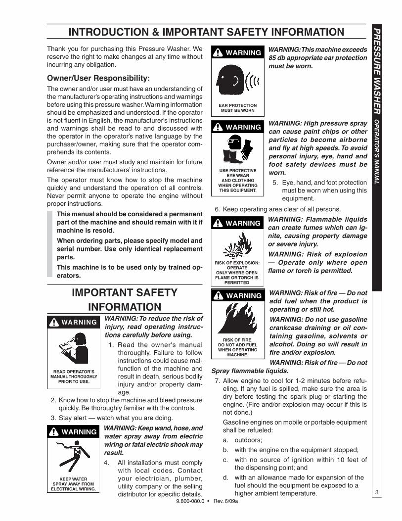
WARNING: To reduce the risk of injury, read operating instruc-tions carefully before using.
1. Read the owner's manual thoroughly. Failure to follow instructions could cause mal-function of the machine and result in death, serious bodily injury and/or property dam-age.
2. Know how to stop the machine and bleed pressure quickly. Be thoroughly familiar with the controls.
3. Stay alert — watch what you are doing.
WARNINg
kEEP WATER SPRAy AWAy fROM
ELECTRICAL WIRINg.
WARNING: Keep wand, hose, and water spray away from electric wiring or fatal electric shock may result.
4. All installations must comply with local codes. Contact your electrician, plumber, utility company or the selling distributor for specific details.
WARNINg
EAR PROTECTION MUST bE WORN
WARNING: This machine exceeds 85 db appropriate ear protection must be worn.
WARNINg
USE PROTECTIvE EyE WEAR
AND CLOThINg WhEN OPERATINg ThIS EqUIPMENT.
WARNING: High pressure spray can cause paint chips or other particles to become airborne and fly at high speeds. To avoid personal injury, eye, hand and foot safety devices must be worn.
5. Eye, hand, and foot protection must be worn when using this equipment.
6. Keep operating area clear of all persons.
RISk Of ExPLOSION: OPERATE
ONLy WhERE OPEN fLAME OR TORCh IS
PERMITTED
WARNINgWARNING: Flammable liquids can create fumes which can ig-nite, causing property damage or severe injury.
WARNING: Risk of explosion — Operate only where open flame or torch is permitted.
RISk Of fIRE. DO NOT ADD fUEL WhEN OPERATINg
MAChINE.
WARNINg WARNING: Risk of fire — Do not add fuel when the product is operating or still hot.
WARNING: Do not use gasoline crankcase draining or oil con-taining gasoline, solvents or alcohol. Doing so will result in fire and/or explosion.
WARNING: Risk of fire — Do not Spray flammable liquids.
7. Allow engine to cool for 1-2 minutes before refu-eling. If any fuel is spilled, make sure the area is dry before testing the spark plug or starting the engine. (Fire and/or explosion may occur if this is not done.)
Gasoline engines on mobile or portable equipment shall be refueled:
a. outdoors;
b. with the engine on the equipment stopped;
c. with no source of ignition within 10 feet of the dispensing point; and
d. with an allowance made for expansion of the fuel should the equipment be exposed to a higher ambient temperature.
9.800-080.0 • Rev. 6/09a
OP
ER
ATO
R’S
MA
NU
AL
P
RE
SS
UR
E W
AS
HE
R
4
14. Never make adjustments on machine while in op-eration.
15. Be certain all quick coupler fittings are secured before using pressure washer.
RISk Of INjECTION OR SEvERE INjURy TO PERSONS. kEEP CLEAR Of NOzzLE.
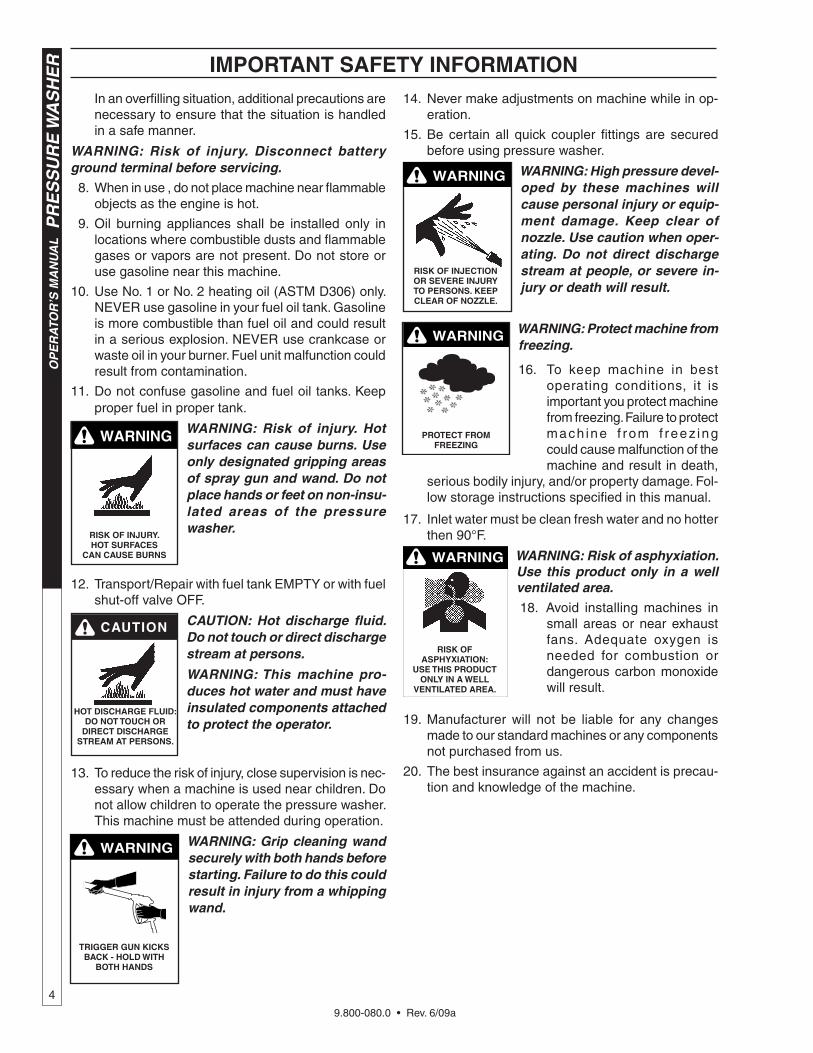
WARNINg WARNING: High pressure devel-oped by these machines will cause personal injury or equip-ment damage. Keep clear of nozzle. Use caution when oper-ating. Do not direct discharge stream at people, or severe in-jury or death will result.
WARNINg
PROTECT fROM fREEzINg
WARNING: Protect machine from freezing.
16. To keep machine in best operating conditions, it is important you protect machine from freezing. Failure to protect mach ine f rom f reez ing could cause malfunction of the machine and result in death,
serious bodily injury, and/or property damage. Fol-low storage instructions specified in this manual.
17. Inlet water must be clean fresh water and no hotter then 90°F.
WARNINg
RISk Of ASPhyxIATION:
USE ThIS PRODUCT ONLy IN A WELL
vENTILATED AREA.
WARNING: Risk of asphyxiation. Use this product only in a well ventilated area.
18. Avoid installing machines in small areas or near exhaust fans. Adequate oxygen is needed for combustion or dangerous carbon monoxide will result.
19. Manufacturer will not be liable for any changes made to our standard machines or any components not purchased from us.
20. The best insurance against an accident is precau-tion and knowledge of the machine.
IMPORTANT SAfETy INfORMATION In an overfilling situation, additional precautions are
necessary to ensure that the situation is handled in a safe manner.
WARNING: Risk of injury. Disconnect battery ground terminal before servicing.
8. When in use , do not place machine near flammable objects as the engine is hot.
9. Oil burning appliances shall be installed only in locations where combustible dusts and flammable gases or vapors are not present. Do not store or use gasoline near this machine.
10. Use No. 1 or No. 2 heating oil (ASTM D306) only. NEVER use gasoline in your fuel oil tank. Gasoline is more combustible than fuel oil and could result in a serious explosion. NEVER use crankcase or waste oil in your burner. Fuel unit malfunction could result from contamination.
11. Do not confuse gasoline and fuel oil tanks. Keep proper fuel in proper tank.
WARNINg
RISk Of INjURy. hOT SURfACES
CAN CAUSE bURNS
WARNING: Risk of injury. Hot surfaces can cause burns. Use only designated gripping areas of spray gun and wand. Do not place hands or feet on non-insu-lated areas of the pressure washer.
12. Transport/Repair with fuel tank EMPTY or with fuel shut-off valve OFF.
hOT DISChARgE fLUID: DO NOT TOUCh OR
DIRECT DISChARgE STREAM AT PERSONS.
CAUTION: Hot discharge fluid. Do not touch or direct discharge stream at persons.
WARNING: This machine pro-duces hot water and must have insulated components attached to protect the operator.
13. To reduce the risk of injury, close supervision is nec-essary when a machine is used near children. Do not allow children to operate the pressure washer. This machine must be attended during operation.
TRIggER gUN kICkS bACk - hOLD WITh
bOTh hANDS
WARNINg WARNING: Grip cleaning wand securely with both hands before starting. Failure to do this could result in injury from a whipping wand.
9.800-080.0 • Rev. 6/09a
5
PR
ES
SU
RE
WA
SH
ER
OP
ER
ATO
R’S
MA
NU
AL
IMPORTANT SAfETy INfORMATION
WARNINg
RISk Of INjURy fROM fALLS WhEN
USINg LADDER.
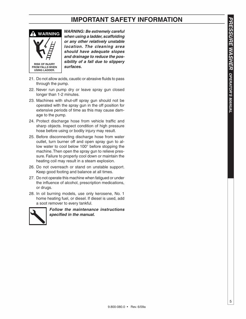
WARNING: Be extremely careful when using a ladder, scaffolding or any other relatively unstable location. The cleaning area should have adequate slopes and drainage to reduce the pos-sibility of a fall due to slippery surfaces.
21. Do not allow acids, caustic or abrasive fluids to pass through the pump.
22. Never run pump dry or leave spray gun closed longer than 1-2 minutes.
23. Machines with shut-off spray gun should not be operated with the spray gun in the off position for extensive periods of time as this may cause dam-age to the pump.
24. Protect discharge hose from vehicle traffic and sharp objects. Inspect condition of high pressure hose before using or bodily injury may result.
25. Before disconnecting discharge hose from water outlet, turn burner off and open spray gun to al-low water to cool below 100° before stopping the machine. Then open the spray gun to relieve pres-sure. Failure to properly cool down or maintain the heating coil may result in a steam explosion.
26. Do not overreach or stand on unstable support. Keep good footing and balance at all times.
27. Do not operate this machine when fatigued or under the influence of alcohol, prescription medications, or drugs.
28. In oil burning models, use only kerosene, No. 1 home heating fuel, or diesel. If diesel is used, add a soot remover to every tankful.
Follow the maintenance instructions specified in the manual.
9.800-080.0 • Rev. 6/09a
OP
ER
ATO
R’S
MA
NU
AL
P
RE
SS
UR
E W
AS
HE
R
6
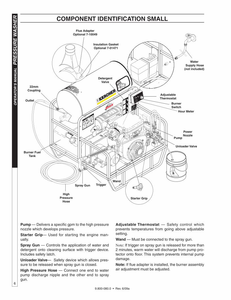
COMPONENT IDENTIfICATION SMALL
Pump — Delivers a specific gpm to the high pressure nozzle which develops pressure.
Starter grip— Used for starting the engine man-ually.
Spray gun — Controls the application of water and detergent onto cleaning surface with trigger device. Includes safety latch.
Unloader valve— Safety device which allows pres-sure to be released when spray gun is closed.
high Pressure hose — Connect one end to water pump discharge nipple and the other end to spray gun.
Adjustable Thermostat — Safety control which prevents temperatures from going above adjustable setting.
Wand — Must be connected to the spray gun.
Note: If trigger on spray gun is released for more than 2 minutes, warm water will discharge from pump pro-tector onto floor. This system prevents internal pump damage.
Note: If flue adapter is installed, the burner assembly air adjustment must be adjusted.
Outlet
high Pressure
hose
22mm Coupling
WandSpray gun Trigger
PowerNozzle
burner fuel Tank
Water Supply hose (not included)
flue AdapterOptional 7-10049
Insulation gasketOptional 7-01471
burner Switch
hour Meter
Adjustable Thermostat
Starter grip
Unloader valve
Detergent valve
Pump
9.800-080.0 • Rev. 6/09a
7
PR
ES
SU
RE
WA
SH
ER
OP
ER
ATO
R’S
MA
NU
AL
Cold Water
Source
garden hose
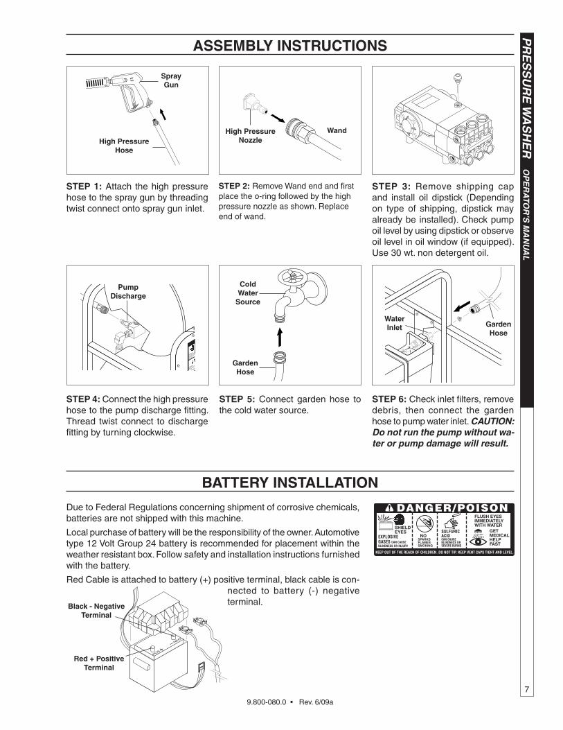
ASSEMbLy INSTRUCTIONS
STEP 1: Attach the high pressure hose to the spray gun by threading twist connect onto spray gun inlet.
STEP 3: Remove shipping cap and install oil dipstick (Depending on type of shipping, dipstick may already be installed). Check pump oil level by using dipstick or observe oil level in oil window (if equipped). Use 30 wt. non detergent oil.
STEP 5: Connect garden hose to the cold water source.
STEP 2: Remove Wand end and first place the o-ring followed by the high pressure nozzle as shown. Replace end of wand.
STEP 6: Check inlet filters, remove debris, then connect the garden hose to pump water inlet. CAUTION: Do not run the pump without wa-ter or pump damage will result.
Spray gun
high Pressure hose
Wandhigh PressureNozzle
STEP 4: Connect the high pressure hose to the pump discharge fitting. Thread twist connect to discharge fitting by turning clockwise.
Water Inlet garden
hose
bATTERy INSTALLATION
Due to Federal Regulations concerning shipment of corrosive chemicals, batteries are not shipped with this machine.
Local purchase of battery will be the responsibility of the owner. Automotive type 12 Volt Group 24 battery is recommended for placement within the weather resistant box. Follow safety and installation instructions furnished with the battery.
Red Cable is attached to battery (+) positive terminal, black cable is con-nected to battery (-) negative terminal.
SHIELD EYES
EXPLOSIVE GASES CAN CAUSE BLINDNESS OR INJURY
NOSPARKSFLAMESSMOKING
SULFURIC ACIDCAN CAUSE BLINDNESS OR SEVERE BURNS
FLUSH EYES IMMEDIATELY WITH WATER
GET MEDICAL HELP FAST
KEEP OUT OF THE REACH OF CHILDREN. DO NOT TIP. KEEP VENT CAPS TIGHT AND LEVEL.
DANGER/POISON
black - Negative Terminal
Red + Positive Terminal
PumpDischarge
9.800-080.0 • Rev. 6/09a
OP
ER
ATO
R’S
MA
NU
AL
PR
ES
SU
RE
WA
SH
ER
8
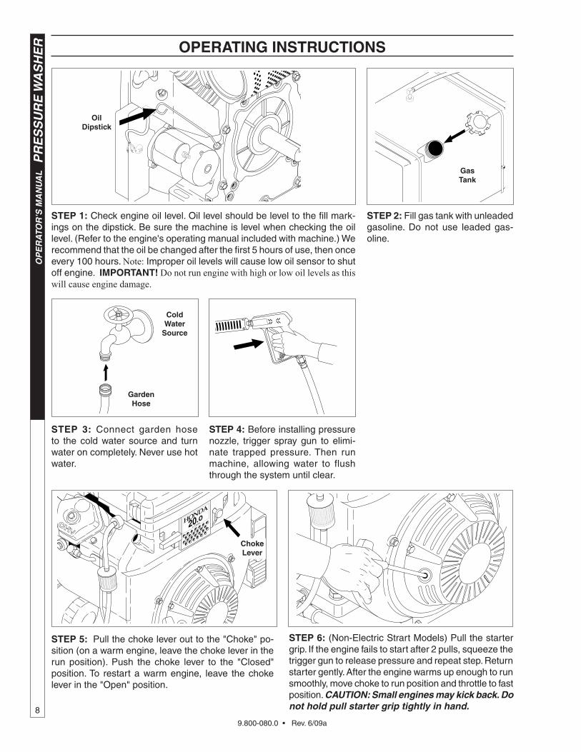
OPERATINg INSTRUCTIONS
STEP 1: Check engine oil level. Oil level should be level to the fill mark-ings on the dipstick. Be sure the machine is level when checking the oil level. (Refer to the engine's operating manual included with machine.) We recommend that the oil be changed after the first 5 hours of use, then once every 100 hours. Note: Improper oil levels will cause low oil sensor to shut off engine. IMPORTANT! Do not run engine with high or low oil levels as this will cause engine damage.
STEP 3: Connect garden hose to the cold water source and turn water on completely. Never use hot water.
STEP 4: Before installing pressure nozzle, trigger spray gun to elimi-nate trapped pressure. Then run machine, allowing water to flush through the system until clear.
STEP 2: Fill gas tank with unleaded gasoline. Do not use leaded gas-oline.
STEP 5: Pull the choke lever out to the "Choke" po-sition (on a warm engine, leave the choke lever in the run position). Push the choke lever to the "Closed" position. To restart a warm engine, leave the choke lever in the "Open" position.
Cold Water
Source
garden hose
STEP 6: (Non-Electric Strart Models) Pull the starter grip. If the engine fails to start after 2 pulls, squeeze the trigger gun to release pressure and repeat step. Return starter gently. After the engine warms up enough to run smoothly, move choke to run position and throttle to fast position. CAUTION: Small engines may kick back. Do not hold pull starter grip tightly in hand.
Oil Dipstick
gas Tank
Choke Lever
9.800-080.0 • Rev. 6/09a
9
PR
ES
SU
RE
WA
SH
ER
OP
ER
ATO
R’S
MA
NU
AL
OPERATINg INSTRUCTIONS
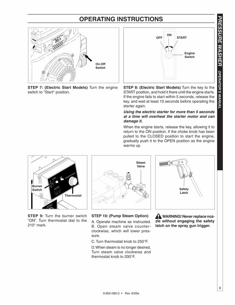
STEP 7: (Electric Start Models) Turn the engine switch to "Start" position.
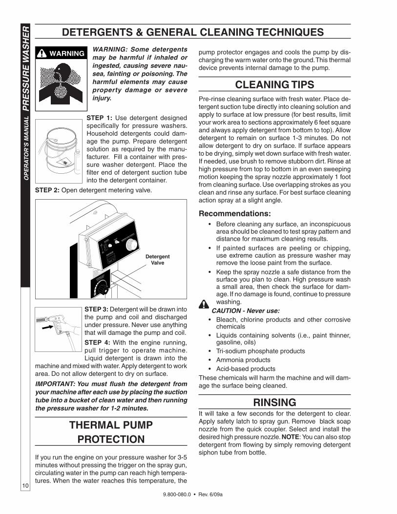
STEP 10: (Pump Steam Option)
A. Operate machine as instructed. B. Open steam valve counter-clockwise, which will lower pres-sure.
C. Turn thermostat knob to 250°F.
D. When steam is no longer desired, Turn steam valve clockwise and thermostat knob to 200°F.
STEP 9: Turn the burner switch “ON”. Turn thermostat dial to the 210° mark.
Thermostat
burner Switch
STEP 8: (Electric Start Models) Turn the key to the START position, and hold it there until the engine starts. If the engine fails to start within 5 seconds, release the key, and wait at least 10 seconds before operating the starter again.
Using the electric starter for more than 5 seconds at a time will overheat the starter motor and can damage it.
When the engine starts, release the key, allowing it to return to the ON position. If the choke knob has been pulled to the CLOSED position to start the engine, gradually push it to the OPEN position as the engine warms up.
Safety Latch
ONOff START
Engine Switch
On-Off Switch
WARNINg! Never replace noz- zle without engaging the safety latch on the spray gun trigger.
Steam valve
9.800-080.0 • Rev. 6/09a
OP
ER
ATO
R’S
MA
NU
AL
P
RE
SS
UR
E W
AS
HE
R
10
WARNING: Some detergents may be harmful if inhaled or ingested, causing severe nau-sea, fainting or poisoning. The harmful elements may cause property damage or severe injury.
STEP 1: Use detergent designed specifically for pressure washers. Household detergents could dam-age the pump. Prepare detergent solution as required by the manu-facturer. Fill a container with pres-sure washer detergent. Place the filter end of detergent suction tube into the detergent container.
STEP 2: Open detergent metering valve.
STEP 3: Detergent will be drawn into the pump and coil and discharged under pressure. Never use anything that will damage the pump and coil.
STEP 4: With the engine running, pull trigger to operate machine. Liquid detergent is drawn into the
machine and mixed with water. Apply detergent to work area. Do not allow detergent to dry on surface.
IMPORTANT: You must flush the detergent from your machine after each use by placing the suction tube into a bucket of clean water and then running the pressure washer for 1-2 minutes.
ThERMAL PUMP PROTECTION
If you run the engine on your pressure washer for 3-5 minutes without pressing the trigger on the spray gun, circulating water in the pump can reach high tempera-tures. When the water reaches this temperature, the
pump protector engages and cools the pump by dis-charging the warm water onto the ground. This thermal device prevents internal damage to the pump.
CLEANINg TIPSPre-rinse cleaning surface with fresh water. Place de-tergent suction tube directly into cleaning solution and apply to surface at low pressure (for best results, limit your work area to sections approximately 6 feet square and always apply detergent from bottom to top). Allow detergent to remain on surface 1-3 minutes. Do not allow detergent to dry on surface. If surface appears to be drying, simply wet down surface with fresh water. If needed, use brush to remove stubborn dirt. Rinse at high pressure from top to bottom in an even sweeping motion keeping the spray nozzle approximately 1 foot from cleaning surface. Use overlapping strokes as you clean and rinse any surface. For best surface cleaning action spray at a slight angle.
Recommendations: • Before cleaning any surface, an inconspicuous
area should be cleaned to test spray pattern and distance for maximum cleaning results.
• If painted surfaces are peeling or chipping, use extreme caution as pressure washer may remove the loose paint from the surface.
• Keep the spray nozzle a safe distance from the surface you plan to clean. High pressure wash a small area, then check the surface for dam-age. If no damage is found, continue to pressure washing.
CAUTION - Never use: • Bleach, chlorine products and other corrosive
chemicals • Liquids containing solvents (i.e., paint thinner,
gasoline, oils) • Tri-sodium phosphate products • Ammonia products • Acid-based productsThese chemicals will harm the machine and will dam-age the surface being cleaned.
RINSINgIt will take a few seconds for the detergent to clear. Apply safety latch to spray gun. Remove black soap nozzle from the quick coupler. Select and install the desired high pressure nozzle. NOTE: You can also stop detergent from flowing by simply removing detergent siphon tube from bottle.
WARNINg
DETERgENTS & gENERAL CLEANINg TEChNIqUES
Detergent valve
9.800-080.0 • Rev. 6/09a
11
PR
ES
SU
RE
WA
SH
ER
OP
ER
ATO
R’S
MA
NU
AL
ShUTTINg DOWN AND CLEAN-UP
STORAgECAUTION: Always store your pressure washer in a location where the temperature will not fall below 32°F (0°C). The pump in this machine is susceptible to permanent damage if frozen. FREEZE DAMAGE IS NOT COVERED BY WARRANTY.
1. Stop the pressure washer, squeeze spray gun trig-ger to release pressure.
2. Detach water supply hose and high pressure hose.
3. Turn on the machine for a few seconds, until re-maining water exits. Turn engine off immediately.
4. Drain the gas and oil from the engine. 5. Do not allow high pressure hose to become
kinked. 6. Store the machine and accessories in a room which
does not reach freezing temperatures.
CAUTION: Failure to follow the above directions will result in damage to your pressure washer.
When the pressure washer is not being operated or is being stored for more than one month, follow these instructions:
1. Replenish engine oil to upper level.
2. Drain gasoline from fuel tank, fuel line, fuel valve and carburetor.
3. Pour about one teaspoon of engine oil through the spark plug hole, pull the starter grip several times and replace the plug. Then pull the starter grip slowly until you feel increased pressure which indicates the piston is on its compression stroke and leave it in that position. This closes both the intake and exhaust valves to prevent rusting of cylinder.
4. Cover pressure washer and store in a clean, dry place that is well ventilated away from open flame or sparks. NOTE: Use of a fuel additive, such as STA-BIL®, or an equivalent, will minimize the formu-lation of fuel deposits during storage. Such additives may be added to the gasoline in the fuel tank of the engine, or to the gasoline in a storage container.
After Extended StorageCAUTION: Prior to restarting, thaw out any possible ice from pressure washer hoses, spray gun or wand.
Engine MaintenanceDuring the winter months, rare atmospheric conditions may develop which will cause an icing condition in the carburetor. If this develops, the engine may run rough, lose power and may stall. This temporary condition can be overcome by deflecting some of the hot air from the engine over the carburetor area. NOTE: Refer to the engine manufacturer's manual for service and mainte-nance of the engine.
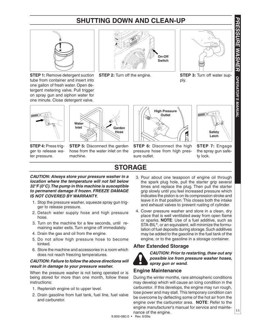
STEP 1: Remove detergent suction tube from container and insert into one gallon of fresh water. Open de-tergent metering valve. Pull trigger on spray gun and siphon water for one minute. Close detergent valve.
STEP 2: Turn off the engine. STEP 3: Turn off water sup-ply.
STEP 5: Disconnect the garden hose from the water inlet on the machine.
STEP 6: Disconnect the high pressure hose from high pres-sure outlet.
STEP 7: Engage the spray gun safe-ty lock.
STEP 4: Press trig-ger to release wa-ter pressure.
On-OffSwitch
Water Inlet
high Pressure Outlet
garden hose Safety
Latch
9.800-080.0 • Rev. 6/09a
OP
ER
ATO
R’S
MA
NU
AL
P
RE
SS
UR
E W
AS
HE
R
12
MAINTENANCE
PREvENTATIvE MAINTENANCE 1. Check to see that water pump is properly lubri-
cated.
2. Follow winterizing instructions to prevent freeze damage to pump and coils.
3. Always neutralize and flush detergent from system after use.
4. If water is known to have high mineral content, use a water softener in your water system, or de-scale as needed.
5. Do not allow acidic, caustic or abrasive fluids to be pumped through system.
6. Always use high grade quality cleaning products.
7. Never run pump dry for extended periods of time.
8. Use clean fuel: kerosene, No. 1 fuel oil, or diesel. Clean or replace fuel filter every 100 hours of operation. Avoid water contaminated fuel as it will damage the fuel pump.
9. If machine is operated with smoky or eye burning exhaust, coils will soot up, not letting water reach maximum operating temperature.
1 0. Never allow water to be sprayed on or near engine or burner assembly or any electrical component.
1 1. Periodically delime coils as per instructions.
1 2. Check to see that engine is properly lubricated.
It is advisable, periodically, to visually inspect the burner. Check air inlet to make sure it is not clogged or blocked. Wipe off any oil spills and keep equipment clean and dry.
The flow of combustion and ventilating air to the burner must not be blocked or obstructed in any manner.
The area around the pressure washer should be kept clean and free of combustible materials, gasoline and other flammable vapors and liquids.
MAINTENANCE AND SERvICEUnloader valves:Unloader valves are preset and tested at the factory before shipping. Occasional adjustment of the unloader may be necessary to maintain correct pressure.
Adjusting Unloader valves:Tampering with the factory setting may cause per-sonal injury and/or property damage and will void the manufacturer's warranty.
Winterizing Procedure:Damage due to freezing is not covered by warranty. Adhere to the following cold weather procedures when-ever the washer must be stored or operated outdoors under freezing conditions.
During winter months, when temperatures drop below 32°F, protecting your machine against freezing is nec-essary. Store the machine in a heated room. If this is not possible then mix a 50/50 solution of anti-freeze and water in the float tank. Turn the engine on to siphon the anti-freeze mixture through the machine. If com-pressed air is available, an air fitting can be screwed into the float tank by removing the float tank strainer and fitting. Then inject the compressed air. Water will be blown out of the machine when the trigger on the spray gun is opened.
high Limit hot Water Thermostat:For safety, each machine is equipped with a tem-perature sensitive high limit control switch. In the event that the water should exceed its operating temperature, the high limit control will turn the burner off until the water cools then it will automatically reset itself. The thermostat sensor is located on the discharge side of the heating coil. The thermostat control dial is located on the control panel.
Pumps:Before running the pump check the pump crankcase for a proper oil level. A proper oil level is indicated by the red dot in the sightglass or between the high and low marks on the dipstick. Use only SAE 30 non-detergent oil. Change the initial oil after the first 50 hours and then change the oil every 500 hours or every three months.
When draining oil, clean inside of crankcase to remove all impurities. CAUTION: When operating in damp places or with high temperature fluctuations oil must be changed immediately.
Cleaning of Coils:In alkaline water areas, lime deposits can accumulate rapidly inside the heating coil. This growth is increased by the extreme heat build up in the coil. The best pre-ventative for liming conditions is to use high quality cleaning detergents. In areas where alkaline water is an extreme problem, periodic use of Coil Conditioner will remove lime and other deposits before coil be-comes plugged. (See Deliming instructions for use of Coil Conditioner.)
9.800-080.0 • Rev. 6/09a
13
PR
ES
SU
RE
WA
SH
ER
OP
ER
ATO
R’S
MA
NU
AL
MAINTENANCE
Deliming Coils:Periodic flushing of coils or optional float tank is rec-ommended.
Step 1 Fill a container with 4 gallons of water, then . add 1 lb. of deliming powder. Mix thoroughly. .. Pour mixture into float tank.
Step 2 Remove wand assembly from spray gun and put spray gun into float tank. Secure the trig- .. ger on the spray gun into the open position.
Step 3 Turn engine on, allowing solution to be pumped through coils back into the float tank. The solution should be allowed to circulate 2- 4 hours or until the color changes.
Step 4 After circulating solution, flush the entire sys-tem with fresh water. Clean out float tank and then reinstall wand assembly to spray gun.
Removal of Soot from heating Coil:In the heating process, fuel residue in the form of soot deposits may develop between the heating coil pipe, and block air flow which will affect burner combustion. When soot has been detected on visual observation, the soot on the coil must be washed off after following the coil removal steps (See Coil Removal section).
Rupture Disk:If pressure from pump or thermal expansion should exceed safe limits, the rupture disk will burst allowing high pressure to be discharged through hose to ground. When disk ruptures it will need to be replaced.
fuel:Use clean fuel oil that is not contaminated with water and debris. Replace fuel filter and drain tank every 100 hours of operation.
Use No.1 or No 2 Heating Oil (ASTM D306) only. NEVER use gasoline in your burner fuel tank. Gasoline is more combustible than fuel oil and could result in a serious explosion. NEVER use crankcase or waste oil in your burner. Fuel unit malfunction could result from contamination.
fuel Control System:This machine utilizes a fuel solenoid valve located on the fuel pump to control the flow of fuel to the combus-tion chamber. The solenoid, which is normally closed, is activated by a flow switch when water flows through it. When the operator releases the trigger on the spray gun, the flow of water through the flow switch stops, turning off the electrical current to the fuel solenoid.
The solenoid then closes, shutting off the supply of fuel to the combustion chamber. Controlling the flow of fuel in this way gives an instantaneous burn-or-no-burn situation, thereby eliminating high and low water
temperatures and the combustion smoke normally associated with machines incorporating a spray gun. Periodic inspection, to insure that the fuel solenoid valve functions properly, is recommended. This can be done by operating the machine and checking to see that the burner is not firing when the spray gun is in the OFF position.
fuel Pressure Adjustment:To control water temperature, adjust fuel pressure by turning the regulating pressure adjusting screw clockwise to increase, counterclockwise to decrease. Do not exceed 200 psi. NOTE: When changing fuel pump, a bypass plug must be installed in return port or fuel pump will not prime.
burner Nozzle:Keep the tip free of surface deposits by wiping it with a clean, solvent saturated cloth, being careful not to plug or enlarge the nozzle. For maximum efficiency, replace the nozzle each season.
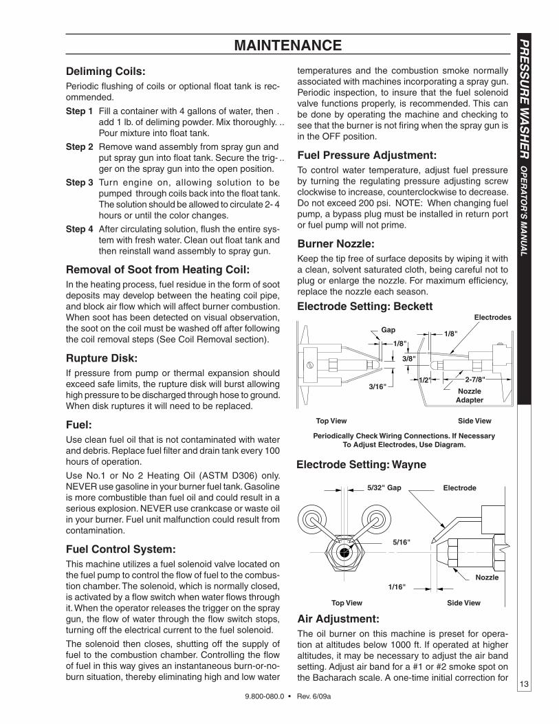
Air Adjustment:The oil burner on this machine is preset for opera-tion at altitudes below 1000 ft. If operated at higher altitudes, it may be necessary to adjust the air band setting. Adjust air band for a #1 or #2 smoke spot on the Bacharach scale. A one-time initial correction for
gap
1/8"1/8"
3/8"
1/2"3/16"
Top view Side view
Nozzle Adapter
2-7/8"
Periodically Check Wiring Connections. If NecessaryTo Adjust Electrodes, Use Diagram.
ElectrodesElectrode Setting: beckett
Electrode Setting: Wayne
1/16"
5/16"
Nozzle
5/32" gap Electrode
Top view Side view
9.800-080.0 • Rev. 6/09a
OP
ER
ATO
R’S
MA
NU
AL
P
RE
SS
UR
E W
AS
HE
R
14
your location will pay off in economy, performance, and extended service life. If a smoky or eye-burning exhaust is being emitted from the stack, two things should be checked. First, check the fuel to be certain that kerosene or No. 1 home heating fuel is being used. Next, check the air adjustment on the burner.
To adjust, start machine and turn burner ON. Loosen two locking screws found in the air shutter openings (refer to illustration) and close air shutter until black smoke appears from burner exhaust vent. Note air band position. Next, slowly open the air shutter until white smoke just starts to appear. Turn air shutter halfway back to the black smoke position previously noted. Tighten locking screws.
MAINTENANCE
If the desired position cannot be obtained using only the air shutter, lock the air shutter in as close a position as can be obtained, then repeat the above procedure on the air band setting.
Coil Removal:Removal of coil because of freeze breakage, or to clean soot from it can be done quickly and easily.
1. Disconnect hose from pump to inlet side of the coil.
2. Carefully disconnect the thermostat sensor making sure you do not crimp the capillary tube.
3. Remove burner assembly from combustion cham-ber.
4. Remove the 3-3/8" bolts from each side of coil and tank assembly (these bolts are used to fasten tank to chassis).
5. Remove fittings connected to the 1/2" pipe nipples from inlet and discharge sides of coil.
6. Remove top tank wrap, bend back insulation tabs and fold back blanket.
7. Remove bolts that hold down coil to bottom wrap.
8. Remove coil.
9. Replace or repair any insulation found to be torn or broken.
10. Remove insulation retainer plates.
Coil Reinstallation:Reinstall new or cleaned coil by reversing Steps
9 through 1.
9.800-080.0 • Rev. 6/09a
15
PR
ES
SU
RE
WA
SH
ER
Trou
blesh
oo
ting
Gu
ide
TROUbLEShOOTINg
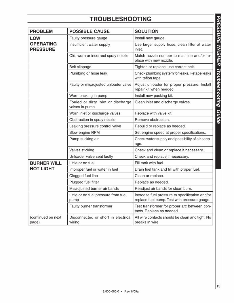
PRObLEM POSSIbLE CAUSE SOLUTION
LOW OPERATINg PRESSURE
Faulty pressure gauge Install new gauge.
Insufficient water supply Use larger supply hose; clean filter at water inlet.
Old, worn or incorrect spray nozzle Match nozzle number to machine and/or re-place with new nozzle.
Belt slippage Tighten or replace; use correct belt.
Plumbing or hose leak Check plumbing system for leaks. Retape leaks with teflon tape.
Faulty or misadjusted unloader valve Adjust unloader for proper pressure. Install repair kit when needed.
Worn packing in pump Install new packing kit.
Fouled or dirty inlet or discharge valves in pump
Clean inlet and discharge valves.
Worn inlet or discharge valves Replace with valve kit.
Obstruction in spray nozzle Remove obstruction.
Leaking pressure control valve Rebuild or replace as needed.
Slow engine RPM Set engine speed at proper specifications.
Pump sucking air Check water supply and possibility of air seep-age.
Valves sticking Check and clean or replace if necessary.
Unloader valve seat faulty Check and replace if necessary.
bURNER WILL NOT LIghT
Little or no fuel Fill tank with fuel.
Improper fuel or water in fuel Drain fuel tank and fill with proper fuel.
Clogged fuel line Clean or replace.
Plugged fuel filter Replace as needed.
Misadjusted burner air bands Readjust air bands for clean burn.
Little or no fuel pressure from fuel pump
Increase fuel pressure to specification and/or replace fuel pump. Test with pressure gauge.
Faulty burner transformer Test transformer for proper arc between con-tacts. Replace as needed.
(continued on next page)
Disconnected or short in electrical wiring
All wire contacts should be clean and tight. No breaks in wire
9.800-080.0 • Rev. 6/09a
PR
ES
SU
RE
WA
SH
ER
Tro
ub
lesh
oo
tin
g G
uid
e
16
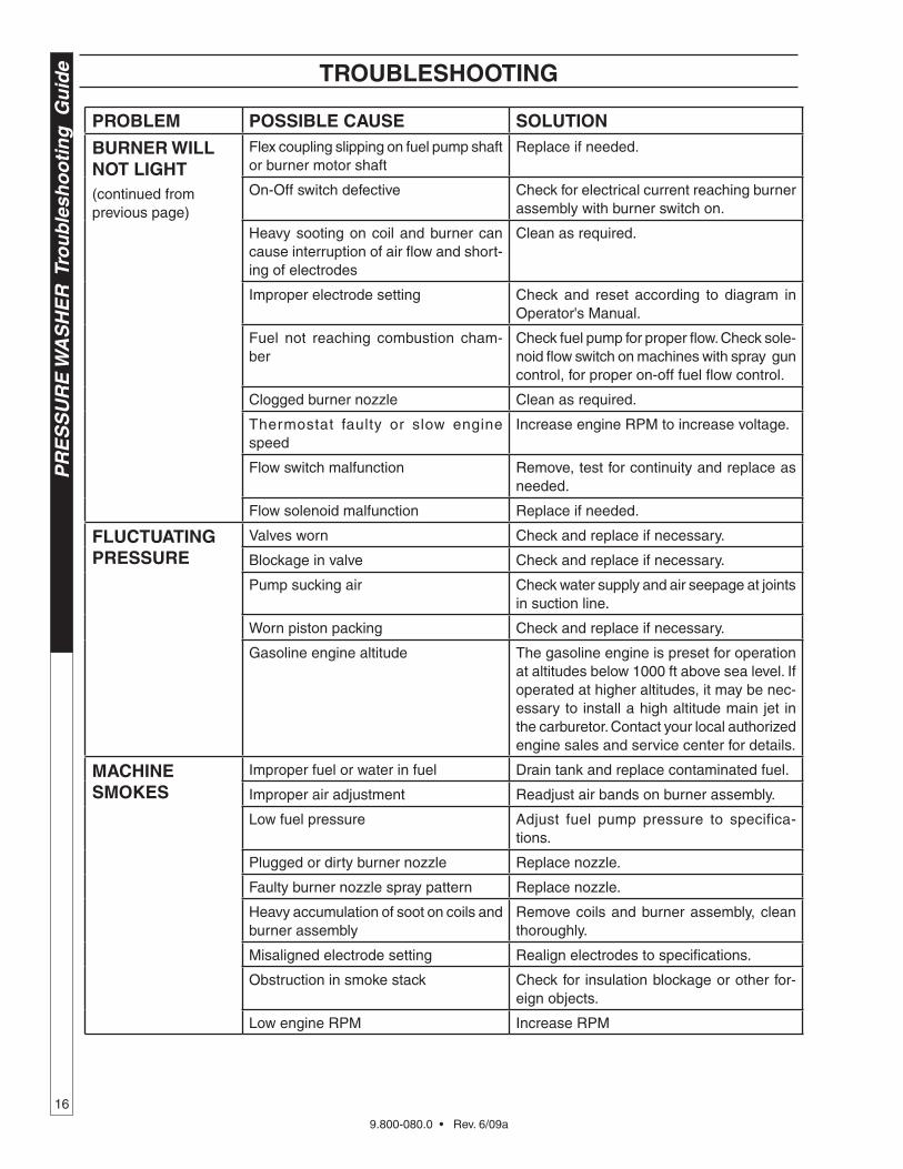
TROUbLEShOOTINg
PRObLEM POSSIbLE CAUSE SOLUTION
bURNER WILL NOT LIghT(continued from previous page)
Flex coupling slipping on fuel pump shaft or burner motor shaft
Replace if needed.
On-Off switch defective Check for electrical current reaching burner assembly with burner switch on.
Heavy sooting on coil and burner can cause interruption of air flow and short-ing of electrodes
Clean as required.
Improper electrode setting Check and reset according to diagram in Operator's Manual.
Fuel not reaching combustion cham-ber
Check fuel pump for proper flow. Check sole-noid flow switch on machines with spray gun control, for proper on-off fuel flow control.
Clogged burner nozzle Clean as required.
Thermostat faulty or slow engine speed
Increase engine RPM to increase voltage.
Flow switch malfunction Remove, test for continuity and replace as needed.
Flow solenoid malfunction Replace if needed.
fLUCTUATINg PRESSURE
Valves worn Check and replace if necessary.
Blockage in valve Check and replace if necessary.
Pump sucking air Check water supply and air seepage at joints in suction line.
Worn piston packing Check and replace if necessary.
Gasoline engine altitude The gasoline engine is preset for operation at altitudes below 1000 ft above sea level. If operated at higher altitudes, it may be nec-essary to install a high altitude main jet in the carburetor. Contact your local authorized engine sales and service center for details.
MAChINE SMOkES
Improper fuel or water in fuel Drain tank and replace contaminated fuel.
Improper air adjustment Readjust air bands on burner assembly.
Low fuel pressure Adjust fuel pump pressure to specifica-tions.
Plugged or dirty burner nozzle Replace nozzle.
Faulty burner nozzle spray pattern Replace nozzle.
Heavy accumulation of soot on coils and burner assembly
Remove coils and burner assembly, clean thoroughly.
Misaligned electrode setting Realign electrodes to specifications.
Obstruction in smoke stack Check for insulation blockage or other for-eign objects.
Low engine RPM Increase RPM
9.800-080.0 • Rev. 6/09a
17
PR
ES
SU
RE
WA
SH
ER
Trou
blesh
oo
ting
Gu
ide
TROUbLEShOOTINg
PRObLEM POSSIbLE CAUSE SOLUTION
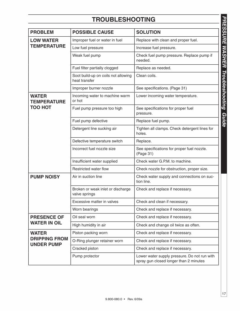
LOW WATER TEMPERATURE
Improper fuel or water in fuel Replace with clean and proper fuel.
Low fuel pressure Increase fuel pressure.
Weak fuel pump Check fuel pump pressure. Replace pump if needed.
Fuel filter partially clogged Replace as needed.
Soot build-up on coils not allowing heat transfer
Clean coils.
Improper burner nozzle See specifications. (Page 31)
WATER TEMPERATURE TOO hOT
Incoming water to machine warm or hot
Lower incoming water temperature.
Fuel pump pressure too high See specifications for proper fuel pressure.
Fuel pump defective Replace fuel pump.
Detergent line sucking air Tighten all clamps. Check detergent lines for holes.
Defective temperature switch Replace.
Incorrect fuel nozzle size See specifications for proper fuel nozzle. (Page 31)
Insufficient water supplied Check water G.P.M. to machine.
Restricted water flow Check nozzle for obstruction, proper size.
PUMP NOISy Air in suction line Check water supply and connections on suc-tion line.
Broken or weak inlet or discharge valve springs
Check and replace if necessary.
Excessive matter in valves Check and clean if necessary.
Worn bearings Check and replace if necessary.
PRESENCE Of WATER IN OIL
Oil seal worn Check and replace if necessary.
High humidity in air Check and change oil twice as often.
WATER DRIPPINg fROM UNDER PUMP
Piston packing worn Check and replace if necessary.
O-Ring plunger retainer worn Check and replace if necessary.
Cracked piston Check and replace if necessary.
Pump protector Lower water supply pressure. Do not run with spray gun closed longer than 2 minutes
9.800-080.0 • Rev. 6/09a
PR
ES
SU
RE
WA
SH
ER
Tro
ub
lesh
oo
tin
g G
uid
e
18
TROUbLEShOOTINg
PRObLEM POSSIbLE CAUSE SOLUTION
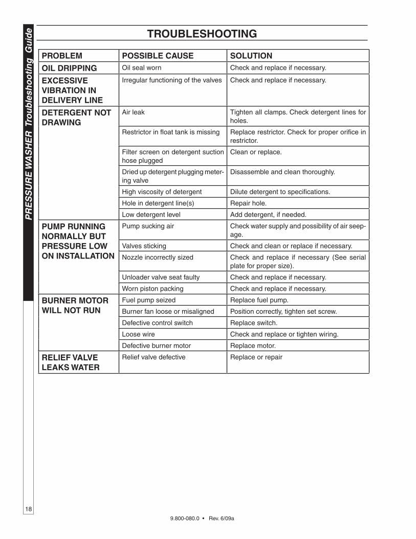
OIL DRIPPINg Oil seal worn Check and replace if necessary.
ExCESSIvE vIbRATION IN DELIvERy LINE
Irregular functioning of the valves Check and replace if necessary.
DETERgENT NOT DRAWINg
Air leak Tighten all clamps. Check detergent lines for holes.
Restrictor in float tank is missing Replace restrictor. Check for proper orifice in restrictor.
Filter screen on detergent suction hose plugged
Clean or replace.
Dried up detergent plugging meter-ing valve
Disassemble and clean thoroughly.
High viscosity of detergent Dilute detergent to specifications.
Hole in detergent line(s) Repair hole.
Low detergent level Add detergent, if needed.
PUMP RUNNINg NORMALLy bUT PRESSURE LOW ON INSTALLATION
Pump sucking air Check water supply and possibility of air seep-age.
Valves sticking Check and clean or replace if necessary.
Nozzle incorrectly sized Check and replace if necessary (See serial plate for proper size).
Unloader valve seat faulty Check and replace if necessary.
Worn piston packing Check and replace if necessary.
bURNER MOTOR WILL NOT RUN
Fuel pump seized Replace fuel pump.
Burner fan loose or misaligned Position correctly, tighten set screw.
Defective control switch Replace switch.
Loose wire Check and replace or tighten wiring.
Defective burner motor Replace motor.
RELIEf vALvE LEAkS WATER
Relief valve defective Replace or repair
9.800-080.0 • Rev. 6/09a
19
PR
ES
SU
RE
WA
SH
ER
OP
ER
ATO
R’S
MA
NU
AL
MAINTENANCE
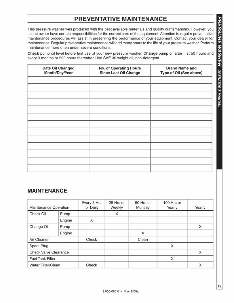
This pressure washer was produced with the best available materials and quality craftsmanship. However, you as the owner have certain responsibilities for the correct care of the equipment. Attention to regular preventative maintenance procedures will assist in preserving the performance of your equipment. Contact your dealer for maintenance. Regular preventative maintenance will add many hours to the life of your pressure washer. Perform maintenance more often under severe conditions.
Check pump oil level before first use of your new pressure washer. Change pump oil after first 50 hours and every 3 months or 500 hours thereafter. Use SAE 30 weight oil, non-detergent.
PREvENTATIvE MAINTENANCE
Date Oil Changed Month/Day/year
No. of Operating hours Since Last Oil Change
brand Name and Type of Oil (See above)
Maintenance OperationEvery 8 Hrs
or Daily25 Hrs or Weekly
50 Hrs or Monthly
100 Hrs or Yearly Yearly
Check Oil Pump X
Engine X
Change Oil Pump X
Engine X
Air Cleaner Check Clean
Spark Plug X
Check Valve Clearance X
Fuel Tank Filter X
Water Filter/Clean Check X
9.800-080.0 • Rev. 6/09a
OP
ER
ATO
R’S
MA
NU
AL
P
RE
SS
UR
E W
AS
HE
R
20
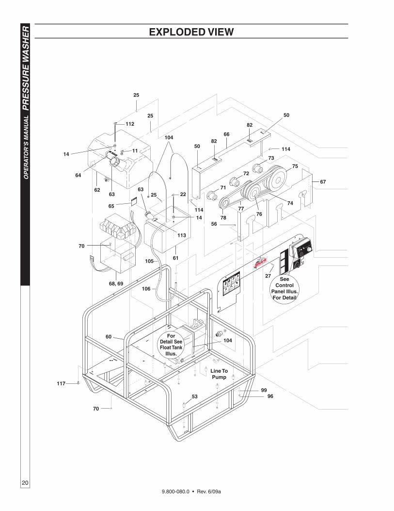
53
66
6362
61
6325
68, 69
70
60
78
SeeControl
Panel Illus.for Detail
27
67
75
74
7677
73
72
71
65
82
50
106
105
14
forDetail See float Tank
Illus.
14
22
11
Line To Pump
5082
114
56
104
70
25
25
64
113
114
9996
117
112
104
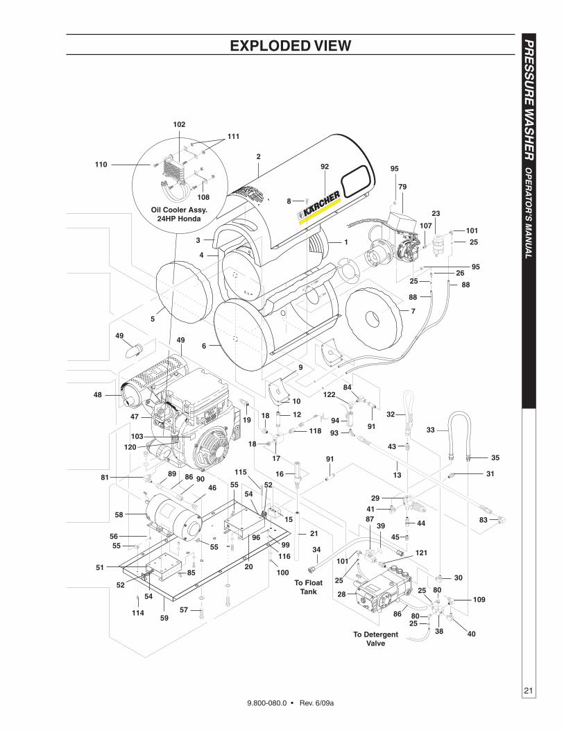
ExPLODED vIEW
9.800-080.0 • Rev. 6/09a
21
PR
ES
SU
RE
WA
SH
ER
OP
ER
ATO
R’S
MA
NU
AL
8146
908689
555556
58
57
5185
52
59
8
2
4
3
38 40
28
44
45
15
20
21
23
107101
25
2625
79
1
7
88
88
83
34
10925
80
116
100 To float
Tank
102
Oil Cooler Assy.24hP honda
To Detergent valve
6
5
49
29
91
5554
52
17
12181932
13
84
9
10
91
49
47
31
35
33
41
115 16
110
111
108
95
95
114
48
9699
54
94
93
ExPLODED vIEW
118103
120
86
25
101
8739
121
30
43
80
25
92
18
122
9.800-080.0 • Rev. 6/09a
OP
ER
ATO
R’S
MA
NU
AL
P
RE
SS
UR
E W
AS
HE
R
22
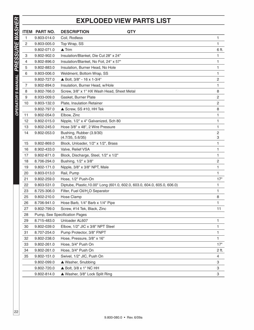
ExPLODED vIEW PARTS LIST
ITEM PART NO. DESCRIPTION qTy 1 9.803-014.0 Coil, Rodless 1
2 9.803-005.0 Top Wrap, SS 1
9.802-071.0 Trim 6 ft.
3 9.802-902.0 Insulation/Blanket, Die Cut 28" x 24" 1
4 9.802-896.0 Insulation/Blanket, No Foil, 24" x 57" 1
5 9.802-883.0 Insulation, Burner Head, No Hole 1
6 9.803-006.0 Weldment, Bottom Wrap, SS 1
9.802-727.0 Bolt, 3/8" - 16 x 1-3/4" 2
7 9.802-894.0 Insulation, Burner Head, w/Hole 1
8 9.802-766.0 Screw, 3/8" x 1" HX Wash Head, Sheet Metal 8
9 8.933-009.0 Gasket, Burner Plate 2
10 9.803-132.0 Plate, Insulation Retainer 2
9.802-797.0 Screw, SS #10, HH Tek 8
11 9.802-054.0 Elbow, Zinc 1
12 9.802-015.0 Nipple, 1/2" x 4" Galvanized, Sch 80 1
13 9.802-245.0 Hose 3/8" x 48", 2 Wire Pressure 1
14 9.802-053.0 Bushing, Rubber (3.9/30) 2 (4.7/35, 5.6/35) 3
15 9.802-869.0 Block, Unloader, 1/2" x 1/2", Brass 1
16 8.902-433.0 Valve, Relief VSA 1
17 9.802-871.0 Block, Discharge, Steel, 1/2" x 1/2" 1
18 8.706-294.0 Bushing, 1/2" x 3/8" 2
19 9.802-171.0 Nipple, 3/8" x 3/8" NPT, Male 1
20 9.803-013.0 Rail, Pump 1
21 9.802-259.0 Hose, 1/2" Push-On 17"
22 9.803-531.0 Diptube, Plastic,10.00" Long (601.0, 602.0, 603.0, 604.0, 605.0, 606.0) 1
23 8.725-306.0 Filter, Fuel Oil/H2O Separator 1
25 9.802-210.0 Hose Clamp 8
26 8.706-941.0 Hose Barb, 1/4" Barb x 1/4" Pipe 1
27 9.802-799.0 Screw, #14 Tek, Black, Zinc 11
28 Pump, See Specification Pages
29 8.715-483.0 Unloader AL607 1
30 9.802-039.0 Elbow, 1/2" JIC x 3/8" NPT Steel 1
31 8.707-254.0 Pump Protector, 3/8" FNPT 1
32 9.802-238.0 Hose, Pressure, 3/8" x 16" 1
33 9.802-261.0 Hose, 3/4" Push On 17"
34 9.802-261.0 Hose, 3/4" Push On 2 ft.
35 9.802-151.0 Swivel, 1/2" JIC, Push On 4
9.802-099.0 Washer, Snubbing 3
9.802-720.0 Bolt, 3/8 x 1" NC HH 3
9.802-814.0 Washer, 3/8" Lock Split Ring 3
9.800-080.0 • Rev. 6/09a
23
PR
ES
SU
RE
WA
SH
ER
OP
ER
ATO
R’S
MA
NU
AL
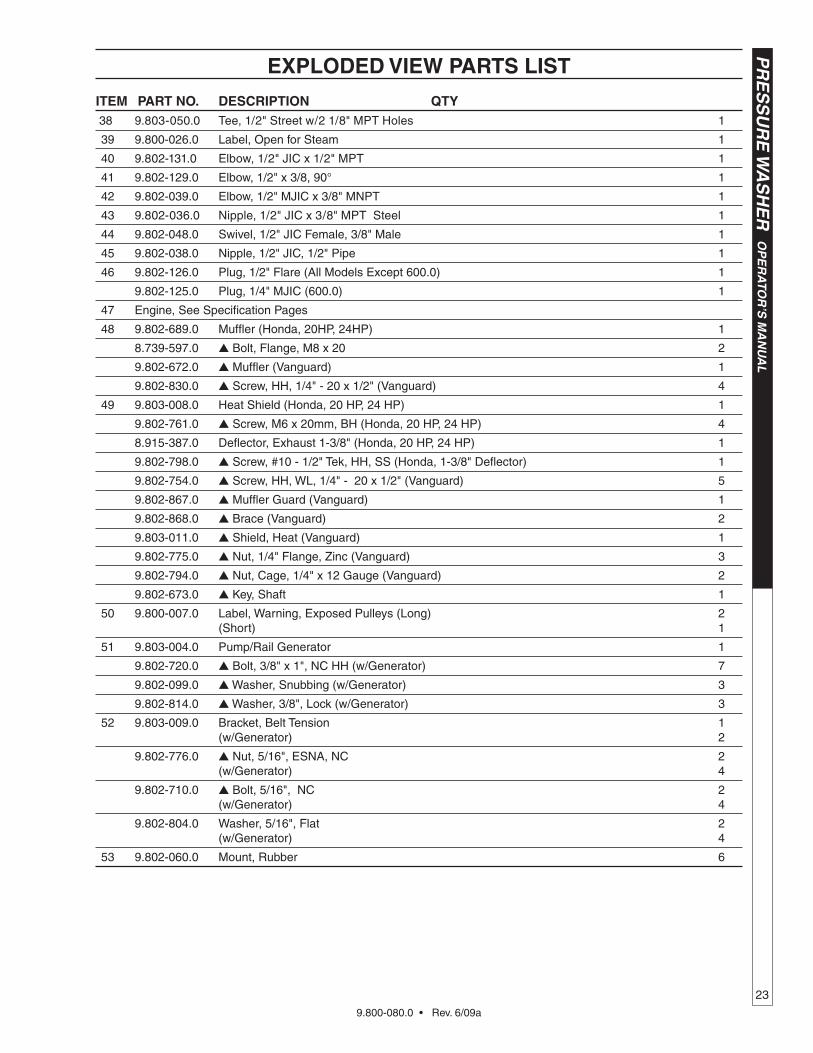
ExPLODED vIEW PARTS LIST
ITEM PART NO. DESCRIPTION qTy 38 9.803-050.0 Tee, 1/2" Street w/2 1/8" MPT Holes 1
39 9.800-026.0 Label, Open for Steam 1
40 9.802-131.0 Elbow, 1/2" JIC x 1/2" MPT 1
41 9.802-129.0 Elbow, 1/2" x 3/8, 90° 1
42 9.802-039.0 Elbow, 1/2" MJIC x 3/8" MNPT 1
43 9.802-036.0 Nipple, 1/2" JIC x 3/8" MPT Steel 1
44 9.802-048.0 Swivel, 1/2" JIC Female, 3/8" Male 1
45 9.802-038.0 Nipple, 1/2" JIC, 1/2" Pipe 1
46 9.802-126.0 Plug, 1/2" Flare (All Models Except 600.0) 1
9.802-125.0 Plug, 1/4" MJIC (600.0) 1
47 Engine, See Specification Pages
48 9.802-689.0 Muffler (Honda, 20HP, 24HP) 1
8.739-597.0 Bolt, Flange, M8 x 20 2
9.802-672.0 Muffler (Vanguard) 1
9.802-830.0 Screw, HH, 1/4" - 20 x 1/2" (Vanguard) 4
49 9.803-008.0 Heat Shield (Honda, 20 HP, 24 HP) 1
9.802-761.0 Screw, M6 x 20mm, BH (Honda, 20 HP, 24 HP) 4
8.915-387.0 Deflector, Exhaust 1-3/8" (Honda, 20 HP, 24 HP) 1
9.802-798.0 Screw, #10 - 1/2" Tek, HH, SS (Honda, 1-3/8" Deflector) 1
9.802-754.0 Screw, HH, WL, 1/4" - 20 x 1/2" (Vanguard) 5
9.802-867.0 Muffler Guard (Vanguard) 1
9.802-868.0 Brace (Vanguard) 2
9.803-011.0 Shield, Heat (Vanguard) 1
9.802-775.0 Nut, 1/4" Flange, Zinc (Vanguard) 3
9.802-794.0 Nut, Cage, 1/4" x 12 Gauge (Vanguard) 2
9.802-673.0 Key, Shaft 1
50 9.800-007.0 Label, Warning, Exposed Pulleys (Long) 2 (Short) 1
51 9.803-004.0 Pump/Rail Generator 1
9.802-720.0 Bolt, 3/8" x 1", NC HH (w/Generator) 7
9.802-099.0 Washer, Snubbing (w/Generator) 3
9.802-814.0 Washer, 3/8", Lock (w/Generator) 3
52 9.803-009.0 Bracket, Belt Tension 1 (w/Generator) 2
9.802-776.0 Nut, 5/16", ESNA, NC 2 (w/Generator) 4
9.802-710.0 Bolt, 5/16", NC 2 (w/Generator) 4
9.802-804.0 Washer, 5/16", Flat 2 (w/Generator) 4
53 9.802-060.0 Mount, Rubber 6
9.800-080.0 • Rev. 6/09a
OP
ER
ATO
R’S
MA
NU
AL
P
RE
SS
UR
E W
AS
HE
R
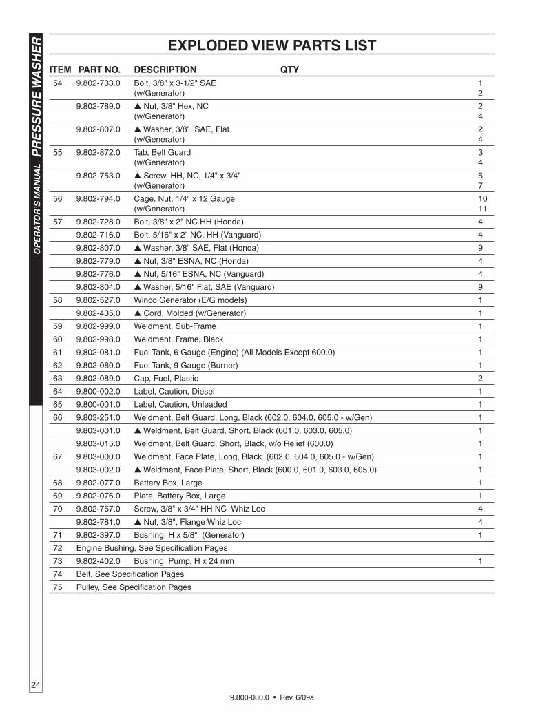
24
ITEM PART NO. DESCRIPTION qTy 54 9.802-733.0 Bolt, 3/8" x 3-1/2" SAE 1 (w/Generator) 2
9.802-789.0 Nut, 3/8" Hex, NC 2 (w/Generator) 4
9.802-807.0 Washer, 3/8", SAE, Flat 2 (w/Generator) 4
55 9.802-872.0 Tab, Belt Guard 3 (w/Generator) 4
9.802-753.0 Screw, HH, NC, 1/4" x 3/4" 6 (w/Generator) 7
56 9.802-794.0 Cage, Nut, 1/4" x 12 Gauge 10 (w/Generator) 11
57 9.802-728.0 Bolt, 3/8" x 2" NC HH (Honda) 4
9.802-716.0 Bolt, 5/16" x 2" NC, HH (Vanguard) 4
9.802-807.0 Washer, 3/8" SAE, Flat (Honda) 9
9.802-779.0 Nut, 3/8" ESNA, NC (Honda) 4
9.802-776.0 Nut, 5/16" ESNA, NC (Vanguard) 4
9.802-804.0 Washer, 5/16" Flat, SAE (Vanguard) 9
58 9.802-527.0 Winco Generator (E/G models) 1
9.802-435.0 Cord, Molded (w/Generator) 1
59 9.802-999.0 Weldment, Sub-Frame 1
60 9.802-998.0 Weldment, Frame, Black 1
61 9.802-081.0 Fuel Tank, 6 Gauge (Engine) (All Models Except 600.0) 1
62 9.802-080.0 Fuel Tank, 9 Gauge (Burner) 1
63 9.802-089.0 Cap, Fuel, Plastic 2
64 9.800-002.0 Label, Caution, Diesel 1
65 9.800-001.0 Label, Caution, Unleaded 1
66 9.803-251.0 Weldment, Belt Guard, Long, Black (602.0, 604.0, 605.0 - w/Gen) 1
9.803-001.0 Weldment, Belt Guard, Short, Black (601.0, 603.0, 605.0) 1
9.803-015.0 Weldment, Belt Guard, Short, Black, w/o Relief (600.0) 1
67 9.803-000.0 Weldment, Face Plate, Long, Black (602.0, 604.0, 605.0 - w/Gen) 1
9.803-002.0 Weldment, Face Plate, Short, Black (600.0, 601.0, 603.0, 605.0) 1
68 9.802-077.0 Battery Box, Large 1
69 9.802-076.0 Plate, Battery Box, Large 1
70 9.802-767.0 Screw, 3/8" x 3/4" HH NC Whiz Loc 4
9.802-781.0 Nut, 3/8", Flange Whiz Loc 4
71 9.802-397.0 Bushing, H x 5/8" (Generator) 1
72 Engine Bushing, See Specification Pages
73 9.802-402.0 Bushing, Pump, H x 24 mm 1
74 Belt, See Specification Pages
75 Pulley, See Specification Pages
ExPLODED vIEW PARTS LIST
9.800-080.0 • Rev. 6/09a
25
PR
ES
SU
RE
WA
SH
ER
OP
ER
ATO
R’S
MA
NU
AL
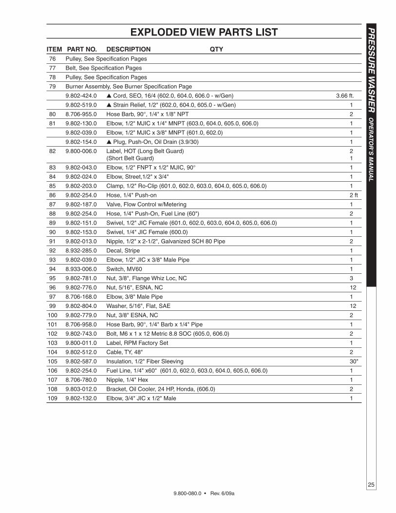
ITEM PART NO. DESCRIPTION qTy 76 Pulley, See Specification Pages
77 Belt, See Specification Pages
78 Pulley, See Specification Pages
79 Burner Assembly, See Burner Specification Page
9.802-424.0 Cord, SEO, 16/4 (602.0, 604.0, 606.0 - w/Gen) 3.66 ft.
9.802-519.0 Strain Relief, 1/2" (602.0, 604.0, 605.0 - w/Gen) 1
80 8.706-955.0 Hose Barb, 90°, 1/4" x 1/8" NPT 2
81 9.802-130.0 Elbow, 1/2" MJIC x 1/4" MNPT (603.0, 604.0, 605.0, 606.0) 1
9.802-039.0 Elbow, 1/2" MJIC x 3/8" MNPT (601.0, 602.0) 1
9.802-154.0 Plug, Push-On, Oil Drain (3.9/30) 1
82 9.800-006.0 Label, HOT (Long Belt Guard) 2 (Short Belt Guard) 1
83 9.802-043.0 Elbow, 1/2" FNPT x 1/2" MJIC, 90° 1
84 9.802-024.0 Elbow, Street,1/2" x 3/4" 1
85 9.802-203.0 Clamp, 1/2" Ro-Clip (601.0, 602.0, 603.0, 604.0, 605.0, 606.0) 1
86 9.802-254.0 Hose, 1/4" Push-on 2 ft
87 9.802-187.0 Valve, Flow Control w/Metering 1
88 9.802-254.0 Hose, 1/4" Push-On, Fuel Line (60") 2
89 9.802-151.0 Swivel, 1/2" JIC Female (601.0, 602.0, 603.0, 604.0, 605.0, 606.0) 1
90 9.802-153.0 Swivel, 1/4" JIC Female (600.0) 1
91 9.802-013.0 Nipple, 1/2" x 2-1/2", Galvanized SCH 80 Pipe 2
92 8.932-285.0 Decal, Stripe 1
93 9.802-039.0 Elbow, 1/2" JIC x 3/8" Male Pipe 1
94 8.933-006.0 Switch, MV60 1
95 9.802-781.0 Nut, 3/8", Flange Whiz Loc, NC 3
96 9.802-776.0 Nut, 5/16", ESNA, NC 12
97 8.706-168.0 Elbow, 3/8" Male Pipe 1
99 9.802-804.0 Washer, 5/16", Flat, SAE 12
100 9.802-779.0 Nut, 3/8" ESNA, NC 2
101 8.706-958.0 Hose Barb, 90°, 1/4" Barb x 1/4" Pipe 1
102 9.802-743.0 Bolt, M6 x 1 x 12 Metric 8.8 SOC (605.0, 606.0) 2
103 9.800-011.0 Label, RPM Factory Set 1
104 9.802-512.0 Cable, TY, 48" 2
105 9.802-587.0 Insulation, 1/2" Fiber Sleeving 30"
106 9.802-254.0 Fuel Line, 1/4" x60" (601.0, 602.0, 603.0, 604.0, 605.0, 606.0) 1
107 8.706-780.0 Nipple, 1/4" Hex 1
108 9.803-012.0 Bracket, Oil Cooler, 24 HP, Honda, (606.0) 2
109 9.802-132.0 Elbow, 3/4" JIC x 1/2" Male 1
ExPLODED vIEW PARTS LIST
9.800-080.0 • Rev. 6/09a
OP
ER
ATO
R’S
MA
NU
AL
P
RE
SS
UR
E W
AS
HE
R
26
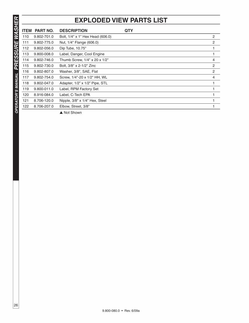
ITEM PART NO. DESCRIPTION qTy 110 9.802-701.0 Bolt, 1/4" x 1" Hex Head (606.0) 2
111 9.802-775.0 Nut, 1/4" Flange (606.0) 2
112 9.802-056.0 Dip Tube, 10.75" 1
113 9.800-008.0 Label, Danger, Cool Engine 1
114 9.802-746.0 Thumb Screw, 1/4" x 20 x 1/2" 4
115 9.802-730.0 Bolt, 3/8" x 2-1/2" Zinc 2
116 9.802-807.0 Washer, 3/8", SAE, Flat 2
117 9.802-754.0 Screw, 1/4"-20 x 1/2" HH, WL 4
118 9.802-047.0 Adapter, 1/2” x 1/2” Pipe, STL 1
119 9.800-011.0 Label, RPM Factory Set 1
120 8.916-084.0 Label, C-Tech EPA 1
121 8.706-120.0 Nipple, 3/8" x 1/4" Hex, Steel 1
122 8.706-207.0 Elbow, Street, 3/8" 1
Not Shown
ExPLODED vIEW PARTS LIST
9.800-080.0 • Rev. 6/09a
27
PR
ES
SU
RE
WA
SH
ER
OP
ER
ATO
R’S
MA
NU
AL
DETERGENT VALVE
VALVULA DE DETERGENTE
SOUPAPE DE DETERGENT
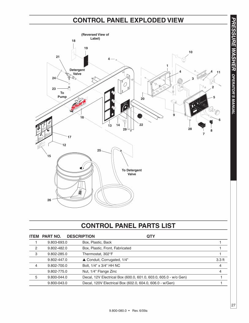
CONTROL PANEL ExPLODED vIEW
ITEM PART NO. DESCRIPTION qTy 1 9.803-693.0 Box, Plastic, Back 1
2 9.802-482.0 Box, Plastic, Front, Fabricated 1
3 9.802-285.0 Thermostat, 302°F 1
9.802-447.0 Conduit, Corrugated, 1/4" 3.3 ft
4 9.802-700.0 Bolt, 1/4" x 3/4" HH NC 4
9.802-775.0 Nut, 1/4" Flange Zinc 4
5 9.800-044.0 Decal, 12V Electrical Box (600.0, 601.0, 603.0, 605.0 - w/o Gen) 1
9.800-043.0 Decal, 120V Electrical Box (602.0, 604.0, 606.0 - w/Gen) 1
(Reversed view of Label)
1
4
20
4
3
9
5
2
6
87
18
19
17
16
22
Detergentvalve
ToPump
To Detergentvalve
10
11
24
21
25
23
4
12
26
CONTROL PANEL PARTS LIST
2813
2914
15
9.800-080.0 • Rev. 6/09a
OP
ER
ATO
R’S
MA
NU
AL
P
RE
SS
UR
E W
AS
HE
R
28
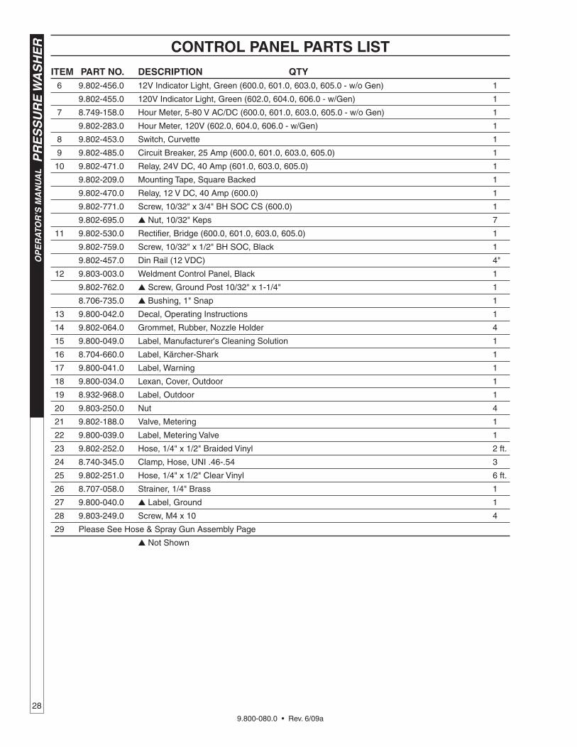
CONTROL PANEL PARTS LIST
ITEM PART NO. DESCRIPTION qTy 6 9.802-456.0 12V Indicator Light, Green (600.0, 601.0, 603.0, 605.0 - w/o Gen) 1
9.802-455.0 120V Indicator Light, Green (602.0, 604.0, 606.0 - w/Gen) 1
7 8.749-158.0 Hour Meter, 5-80 V AC/DC (600.0, 601.0, 603.0, 605.0 - w/o Gen) 1
9.802-283.0 Hour Meter, 120V (602.0, 604.0, 606.0 - w/Gen) 1
8 9.802-453.0 Switch, Curvette 1
9 9.802-485.0 Circuit Breaker, 25 Amp (600.0, 601.0, 603.0, 605.0) 1
10 9.802-471.0 Relay, 24V DC, 40 Amp (601.0, 603.0, 605.0) 1
9.802-209.0 Mounting Tape, Square Backed 1
9.802-470.0 Relay, 12 V DC, 40 Amp (600.0) 1
9.802-771.0 Screw, 10/32" x 3/4" BH SOC CS (600.0) 1
9.802-695.0 Nut, 10/32" Keps 7
11 9.802-530.0 Rectifier, Bridge (600.0, 601.0, 603.0, 605.0) 1
9.802-759.0 Screw, 10/32" x 1/2" BH SOC, Black 1
9.802-457.0 Din Rail (12 VDC) 4"
12 9.803-003.0 Weldment Control Panel, Black 1
9.802-762.0 Screw, Ground Post 10/32" x 1-1/4" 1
8.706-735.0 Bushing, 1" Snap 1
13 9.800-042.0 Decal, Operating Instructions 1
14 9.802-064.0 Grommet, Rubber, Nozzle Holder 4
15 9.800-049.0 Label, Manufacturer's Cleaning Solution 1
16 8.704-660.0 Label, Kärcher-Shark 1
17 9.800-041.0 Label, Warning 1
18 9.800-034.0 Lexan, Cover, Outdoor 1
19 8.932-968.0 Label, Outdoor 1
20 9.803-250.0 Nut 4
21 9.802-188.0 Valve, Metering 1
22 9.800-039.0 Label, Metering Valve 1
23 9.802-252.0 Hose, 1/4" x 1/2" Braided Vinyl 2 ft.
24 8.740-345.0 Clamp, Hose, UNI .46-.54 3
25 9.802-251.0 Hose, 1/4" x 1/2" Clear Vinyl 6 ft.
26 8.707-058.0 Strainer, 1/4" Brass 1
27 9.800-040.0 Label, Ground 1
28 9.803-249.0 Screw, M4 x 10 4
29 Please See Hose & Spray Gun Assembly Page
Not Shown
9.800-080.0 • Rev. 6/09a
29
PR
ES
SU
RE
WA
SH
ER
OP
ER
ATO
R’S
MA
NU
AL
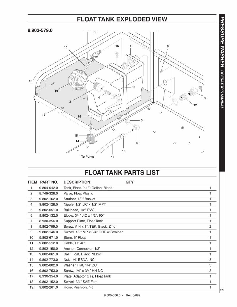
fLOAT TANk ExPLODED vIEW
ITEM PART NO. DESCRIPTION qTy 1 9.804-042.0 Tank, Float, 2-1/2 Gallon, Blank 1
2 8.749-328.0 Valve, Float Plastic 1
3 9.802-162.0 Strainer, 1/2" Basket 1
4 9.802-128.0 Nipple, 1/2" JIC x 1/2" MPT 1
5 9.802-051.0 Bulkhead, 1/2" PVC 1
6 9.802-132.0 Elbow, 3/4" JIC x 1/2", 90° 1
7 8.930-356.0 Support Plate, Float Tank 1
8 9.802-799.0 Screw, #14 x 1", TEK, Black, Zinc 2
9 9.802-146.0 Swivel, 1/2" MP x 3/4" GHF w/Strainer 1
10 9.803-671.0 Stem, 5" Float 1
11 9.802-512.0 Cable, TY, 48" 1
12 9.802-150.0 Anchor, Connector, 1/2" 1
13 9.802-061.0 Ball, Float, Black Plastic 1
14 9.802-773.0 Nut, 1/4" ESNA, NC 3
15 9.802-802.0 Washer, Flat, 1/4" ZC 3
16 9.802-753.0 Screw, 1/4" x 3/4" HH NC 3
17 8.930-354.0 Plate, Adaptor Gas, Float Tank 1
18 9.802-152.0 Swivel, 3/4" SAE Fem 1
19 9.802-261.0 Hose, Push-on, /Ft 1
7
2
3
11
6
5
1 8
94
To Pump
13
10
12
fLOAT TANk PARTS LIST
14
15
16
16
1617
18
19
8.903-579.0
9.800-080.0 • Rev. 6/09a
OP
ER
ATO
R’S
MA
NU
AL
P
RE
SS
UR
E W
AS
HE
R
30
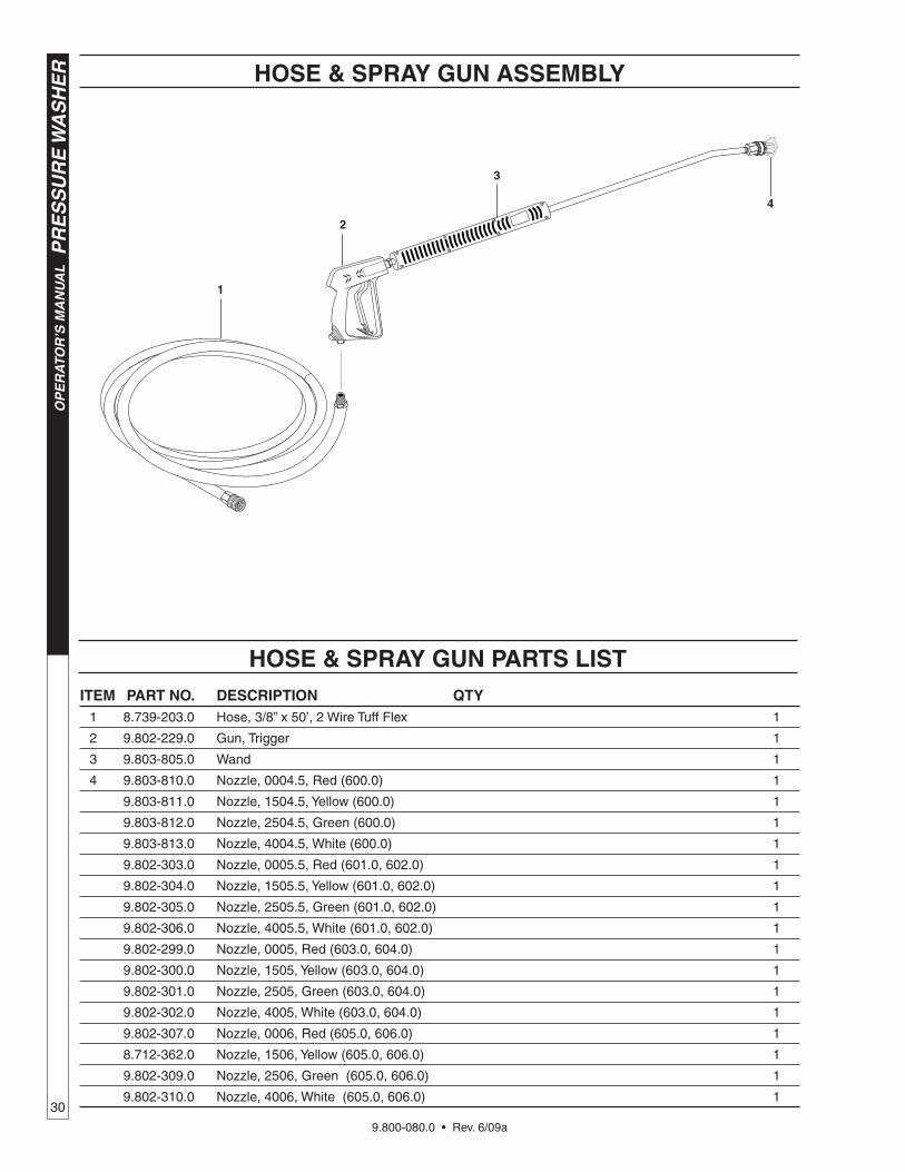
hOSE & SPRAy gUN ASSEMbLy
hOSE & SPRAy gUN PARTS LIST
4
3
2
1
ITEM PART NO. DESCRIPTION qTy 1 8.739-203.0 Hose, 3/8” x 50’, 2 Wire Tuff Flex 1
2 9.802-229.0 Gun, Trigger 1
3 9.803-805.0 Wand 1
4 9.803-810.0 Nozzle, 0004.5, Red (600.0) 1
9.803-811.0 Nozzle, 1504.5, Yellow (600.0) 1
9.803-812.0 Nozzle, 2504.5, Green (600.0) 1
9.803-813.0 Nozzle, 4004.5, White (600.0) 1
9.802-303.0 Nozzle, 0005.5, Red (601.0, 602.0) 1
9.802-304.0 Nozzle, 1505.5, Yellow (601.0, 602.0) 1
9.802-305.0 Nozzle, 2505.5, Green (601.0, 602.0) 1
9.802-306.0 Nozzle, 4005.5, White (601.0, 602.0) 1
9.802-299.0 Nozzle, 0005, Red (603.0, 604.0) 1
9.802-300.0 Nozzle, 1505, Yellow (603.0, 604.0) 1
9.802-301.0 Nozzle, 2505, Green (603.0, 604.0) 1
9.802-302.0 Nozzle, 4005, White (603.0, 604.0) 1
9.802-307.0 Nozzle, 0006, Red (605.0, 606.0) 1
8.712-362.0 Nozzle, 1506, Yellow (605.0, 606.0) 1
9.802-309.0 Nozzle, 2506, Green (605.0, 606.0) 1
9.802-310.0 Nozzle, 4006, White (605.0, 606.0) 1
9.800-080.0 • Rev. 6/09a
31
PR
ES
SU
RE
WA
SH
ER
Sp
ecificatio
ns
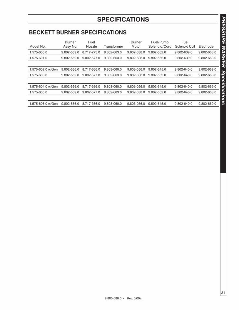
Model No.Burner
Assy No.Fuel
Nozzle TransformerBurner Motor
Fuel/Pump Solenoid/Cord
FuelSolenoid Coil Electrode
1.575-600.0 9.802-559.0 8.717-273.0 9.802-663.0 9.802-638.0 9.802-562.0 9.802-639.0 9.802-668.0
1.575-601.0 9.802-559.0 9.802-577.0 9.802-663.0 9.802-638.0 9.802-562.0 9.802-639.0 9.802-668.0
1.575-602.0 w/Gen 9.802-556.0 8.717-366.0 9.803-060.0 9.803-056.0 9.802-645.0 9.802-640.0 9.802-669.0
1.575-603.0 9.802-559.0 9.802-577.0 9.802-663.0 9.802-638.0 9.802-562.0 9.802-640.0 9.802-668.0
1.575-604.0 w/Gen 9.802-556.0 8.717-366.0 9.803-060.0 9.803-056.0 9.802-645.0 9.802-640.0 9.802-669.0
1.575-605.0 9.802-559.0 9.802-577.0 9.802-663.0 9.802-638.0 9.802-562.0 9.802-640.0 9.802-668.0
1.575-606.0 w/Gen 9.802-556.0 8.717-366.0 9.803-060.0 9.803-056.0 9.802-645.0 9.802-640.0 9.802-669.0
bECkETT bURNER SPECIfICATIONS
SPECIfICATIONS
9.800-080.0 • Rev. 6/09a
PR
ES
SU
RE
WA
SH
ER
Sp
ecifi
cati
on
s
32
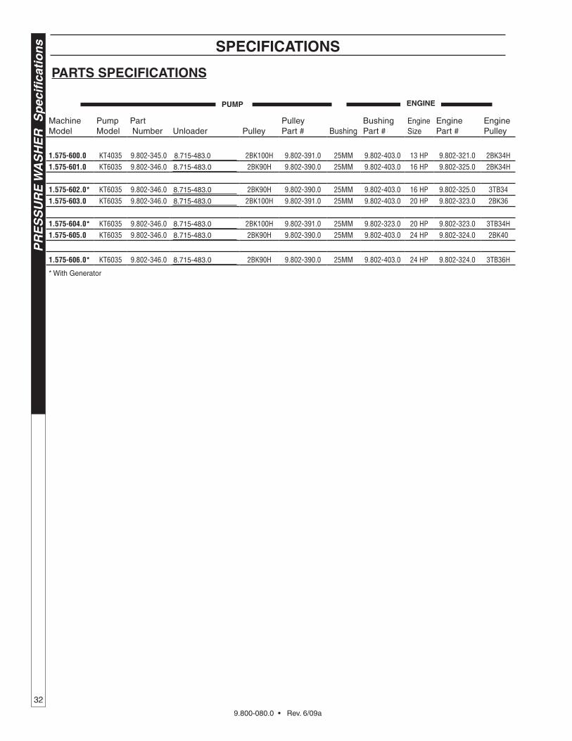
SPECIfICATIONS
PARTS SPECIfICATIONS
Machine Model
Pump Model
Part Number Unloader Pulley
Pulley Part # Bushing
Bushing Part #
Engine Size
Engine Part #
Engine Pulley Model
Pulley Part # Bushing
Bushing Part #
Belt Size
Belt Part # Pulley
Pulley Part # Belt
Belt Part # Bushing Part No.
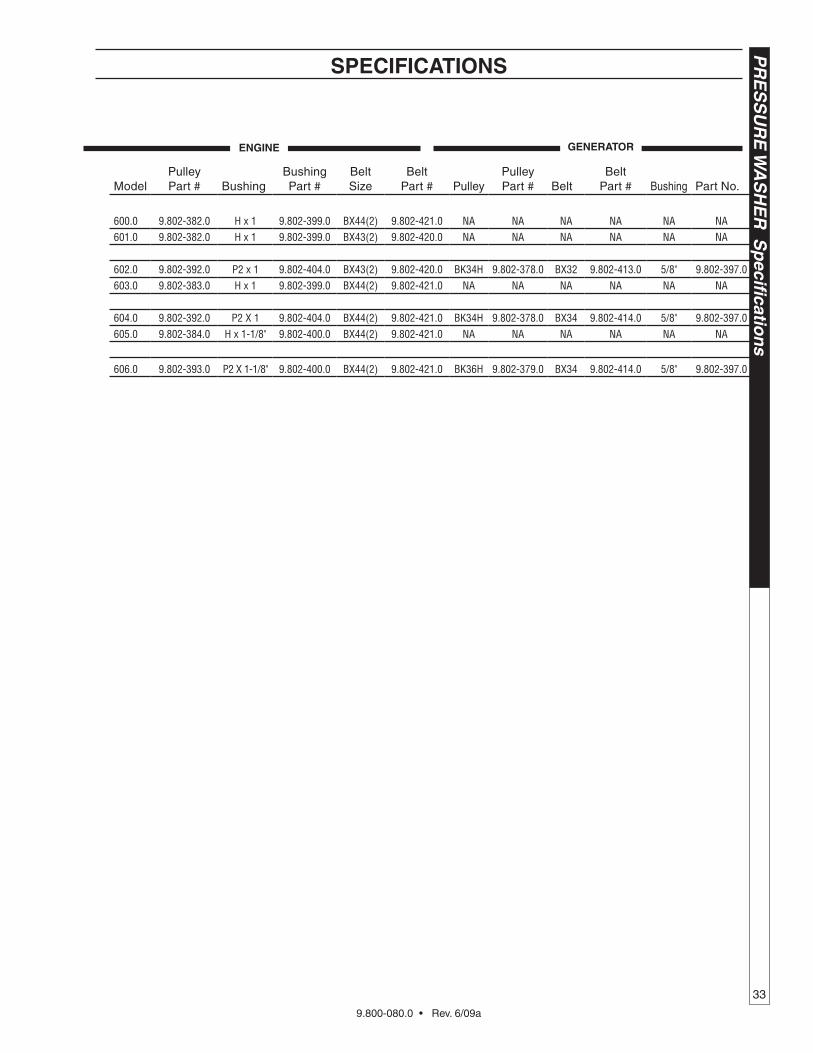
1.575-600.0 KT4035 9.802-345.0 8.715-483.0 2BK100H 9.802-391.0 25MM 9.802-403.0 13 HP 9.802-321.0 2BK34H 600.0 9.802-382.0 H x 1 9.802-399.0 BX44(2) 9.802-421.0 NA NA NA NA NA NA1.575-601.0 KT6035 9.802-346.0 8.715-483.0 2BK90H 9.802-390.0 25MM 9.802-403.0 16 HP 9.802-325.0 2BK34H 601.0 9.802-382.0 H x 1 9.802-399.0 BX43(2) 9.802-420.0 NA NA NA NA NA NA
1.575-602.0* KT6035 9.802-346.0 8.715-483.0 2BK90H 9.802-390.0 25MM 9.802-403.0 16 HP 9.802-325.0 3TB34 602.0 9.802-392.0 P2 x 1 9.802-404.0 BX43(2) 9.802-420.0 BK34H 9.802-378.0 BX32 9.802-413.0 5/8" 9.802-397.01.575-603.0 KT6035 9.802-346.0 8.715-483.0 2BK100H 9.802-391.0 25MM 9.802-403.0 20 HP 9.802-323.0 2BK36 603.0 9.802-383.0 H x 1 9.802-399.0 BX44(2) 9.802-421.0 NA NA NA NA NA NA
1.575-604.0* KT6035 9.802-346.0 8.715-483.0 2BK100H 9.802-391.0 25MM 9.802-323.0 20 HP 9.802-323.0 3TB34H 604.0 9.802-392.0 P2 X 1 9.802-404.0 BX44(2) 9.802-421.0 BK34H 9.802-378.0 BX34 9.802-414.0 5/8" 9.802-397.01.575-605.0 KT6035 9.802-346.0 8.715-483.0 2BK90H 9.802-390.0 25MM 9.802-403.0 24 HP 9.802-324.0 2BK40 605.0 9.802-384.0 H x 1-1/8" 9.802-400.0 BX44(2) 9.802-421.0 NA NA NA NA NA NA
1.575-606.0* KT6035 9.802-346.0 8.715-483.0 2BK90H 9.802-390.0 25MM 9.802-403.0 24 HP 9.802-324.0 3TB36H 606.0 9.802-393.0 P2 X 1-1/8" 9.802-400.0 BX44(2) 9.802-421.0 BK36H 9.802-379.0 BX34 9.802-414.0 5/8" 9.802-397.0
* With Generator
gENERATORPUMP ENgINE ENgINE
9.800-080.0 • Rev. 6/09a
33
PR
ES
SU
RE
WA
SH
ER
Sp
ecificatio
ns
Machine Model
Pump Model
Part Number Unloader Pulley
Pulley Part # Bushing
Bushing Part #
Engine Size
Engine Part #
Engine Pulley Model
Pulley Part # Bushing
Bushing Part #
Belt Size
Belt Part # Pulley
Pulley Part # Belt
Belt Part # Bushing Part No.
1.575-600.0 KT4035 9.802-345.0 8.715-483.0 2BK100H 9.802-391.0 25MM 9.802-403.0 13 HP 9.802-321.0 2BK34H 600.0 9.802-382.0 H x 1 9.802-399.0 BX44(2) 9.802-421.0 NA NA NA NA NA NA1.575-601.0 KT6035 9.802-346.0 8.715-483.0 2BK90H 9.802-390.0 25MM 9.802-403.0 16 HP 9.802-325.0 2BK34H 601.0 9.802-382.0 H x 1 9.802-399.0 BX43(2) 9.802-420.0 NA NA NA NA NA NA
1.575-602.0* KT6035 9.802-346.0 8.715-483.0 2BK90H 9.802-390.0 25MM 9.802-403.0 16 HP 9.802-325.0 3TB34 602.0 9.802-392.0 P2 x 1 9.802-404.0 BX43(2) 9.802-420.0 BK34H 9.802-378.0 BX32 9.802-413.0 5/8" 9.802-397.01.575-603.0 KT6035 9.802-346.0 8.715-483.0 2BK100H 9.802-391.0 25MM 9.802-403.0 20 HP 9.802-323.0 2BK36 603.0 9.802-383.0 H x 1 9.802-399.0 BX44(2) 9.802-421.0 NA NA NA NA NA NA
1.575-604.0* KT6035 9.802-346.0 8.715-483.0 2BK100H 9.802-391.0 25MM 9.802-323.0 20 HP 9.802-323.0 3TB34H 604.0 9.802-392.0 P2 X 1 9.802-404.0 BX44(2) 9.802-421.0 BK34H 9.802-378.0 BX34 9.802-414.0 5/8" 9.802-397.01.575-605.0 KT6035 9.802-346.0 8.715-483.0 2BK90H 9.802-390.0 25MM 9.802-403.0 24 HP 9.802-324.0 2BK40 605.0 9.802-384.0 H x 1-1/8" 9.802-400.0 BX44(2) 9.802-421.0 NA NA NA NA NA NA
1.575-606.0* KT6035 9.802-346.0 8.715-483.0 2BK90H 9.802-390.0 25MM 9.802-403.0 24 HP 9.802-324.0 3TB36H 606.0 9.802-393.0 P2 X 1-1/8" 9.802-400.0 BX44(2) 9.802-421.0 BK36H 9.802-379.0 BX34 9.802-414.0 5/8" 9.802-397.0
* With Generator
SPECIfICATIONS
gENERATORPUMP ENgINE ENgINE
9.800-080.0 • Rev. 6/09a
OP
ER
ATO
R’S
MA
NU
AL
P
RE
SS
UR
E W
AS
HE
R
34
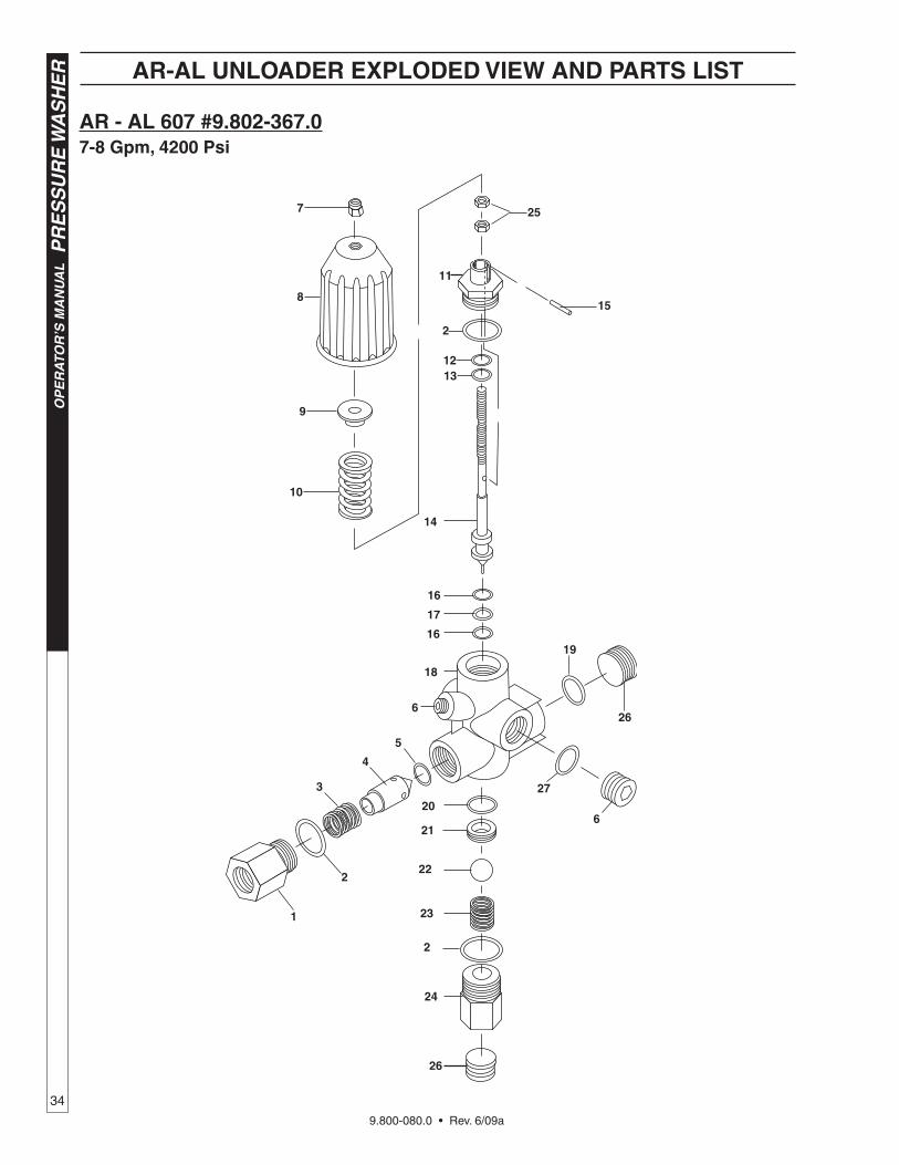
AR - AL 607 #9.802-367.07-8 gpm, 4200 Psi
24
2
23
22
21
20
1
2
3
4
5
27
6
26
19
6
14
16
17
16
18
1312
2
15
257
9
10
11
8
26
AR-AL UNLOADER ExPLODED vIEW AND PARTS LIST
9.800-080.0 • Rev. 6/09a
35
PR
ES
SU
RE
WA
SH
ER
OP
ER
ATO
R’S
MA
NU
AL
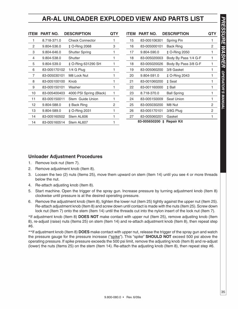
ITEM PART NO. DESCRIPTION qTy
1 8.718-371.0 Check Connector 1
2 9.804-536.0 ‡ O-Ring 2068 3
3 9.804-646.0 Shutter Spring 1
4 9.804-538.0 Shutter 1
5 9.804-539.0 ‡ O-Ring 631290 SH 1
6 83-005170102 1/4 G Plug 1
7 83-005030101 M8 Lock Nut 1
8 83-005100100 Knob 1
9 83-005150101 Washer 1
10 83-005400403 4000 PSI Spring (Black) 1
11 83-005150011 Stem Guide Union 1
12 9.804-588.0 ‡ Back Ring 2
13 9.804-589.0 ‡ O-Ring 2031 1
14 83-005160502 Stem AL606 1
14 83-005160514 Stem AL607 1
Unloader Adjustment ProceduresRemove lock nut (Item 7).
Remove adjustment knob (Item 8).
Loosen the two (2) nuts (Items 25), move them upward on stem (Item 14) until you see 4 or more threads below the nut.
Re-attach adjusting knob (Item 8).
Start machine. Open the trigger of the spray gun. Increase pressure by turning adjustment knob (Item 8) clockwise until pressure is at the desired operating pressure.
Remove the adjustment knob (Item 8), tighten the lower nut (item 25) tightly against the upper nut (Item 25). Re-attach adjustment knob (Item 8) and screw down until contact is made with the nuts (Item 25). Screw down lock nut (Item 7) onto the stem (Item 14) until the threads cut into the nylon insert of the lock nut (Item 7).
*If adjustment knob (Item 8) DOES NOT make contact with upper nut (Item 25), remove adjusting knob (Item 8), re-adjust (raise) nuts (Items 25) on stem (Item 14) and re-attach adjustment knob (Item 8), then repeat step #6.
**If adjustment knob (Item 8) DOES make contact with upper nut, release the trigger of the spray gun and watch the pressure gauge for the pressure increase (“spike”). This “spike” ShOULD NOT exceed 500 psi above the operating pressure. If spike pressure exceeds the 500 psi limit, remove the adjusting knob (Item 8) and re-adjust (lower) the nuts (Items 25) on the stem (Item 14). Re-attach the adjusting knob (Item 8), then repeat step #6.
1.
2.
3.
4.
5.
6.
AR-AL UNLOADER ExPLODED vIEW AND PARTS LIST
ITEM PART NO. DESCRIPTION qTy
15 83-005106301 Spring Pin 1
16 83-005000101 Back Ring 2
17 9.804-590.0 ‡ O-Ring 2050 1
18 83-005020003 Body By Pass 1/4 G-F 1
18 83-005020026 Body By Pass 3/8 G-F 1
19 83-005060200 3/8 Gasket 1
20 9.804-591.0 ‡ O-Ring 2043 1
21 83-001060200 ‡ Seat 1
22 83-001160000 ‡ Ball 1
23 8.718-370.0 Ball Spring 1
24 83-005150009 Seat Union 1
25 83-005030200 M8 Nut 2
26 83-005170101 3/8G Plug 2
27 83-005060201 Gasket 1 83-005650200 ‡ Repair kit
9.800-080.0 • Rev. 6/09a
OP
ER
ATO
R’S
MA
NU
AL
P
RE
SS
UR
E W
AS
HE
R
36
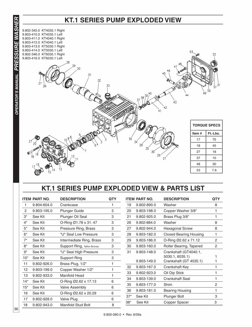
9.802-345.0 KT4035.1 Right9.803-410.0 KT4035.1 Left 9.803-411.0 KT4040.1 Right9.803-412.0 KT4040.1 Left9.803-413.0 KT5030.1 Right9.803-414.0 KT5030.1 Left9.802-346.0 KT6035.1 Right9.803-416.0 KT6035.1 Left
kT.1 SERIES PUMP ExPLODED vIEW
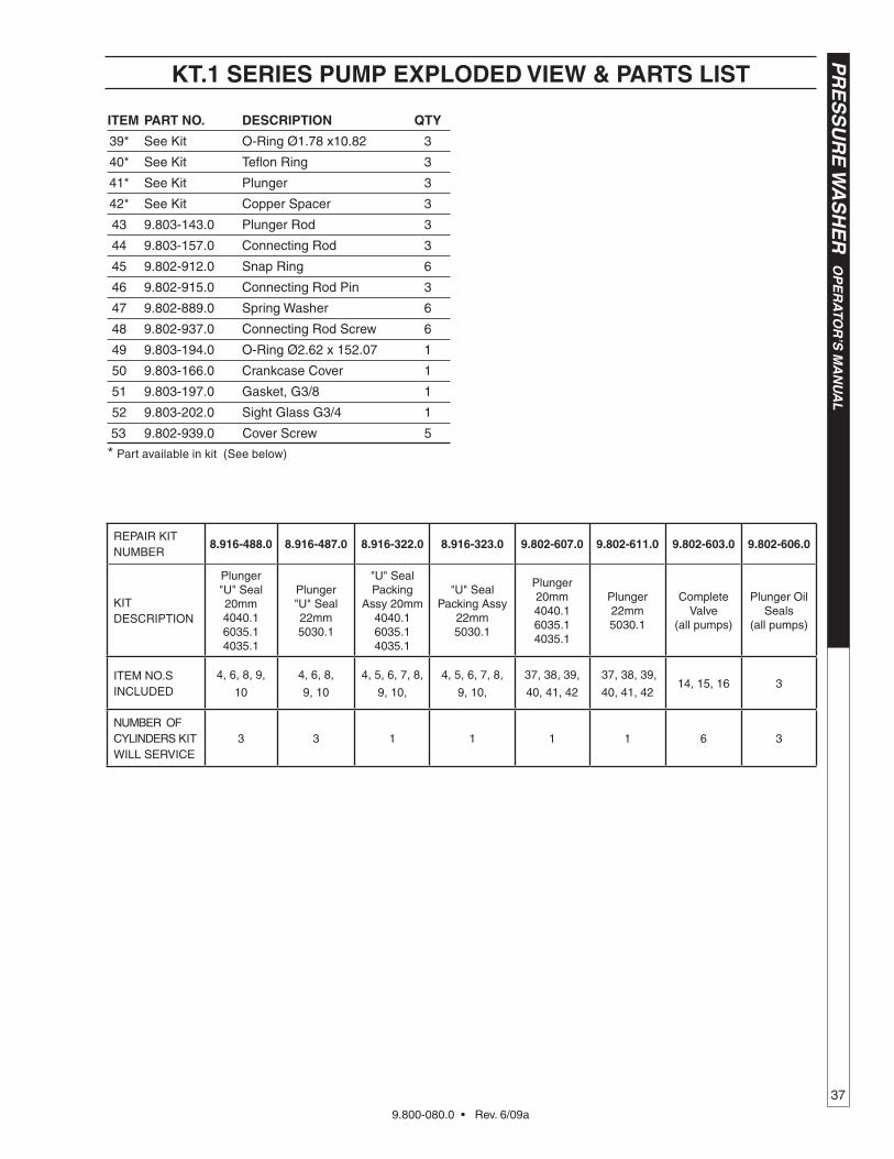
kT.1 SERIES PUMP ExPLODED vIEW & PARTS LIST
TORqUE SPECS
Item # ft.-Lbs.
17 75
18 45
27 18
37 10
48 30
53 7.6
ITEM PART NO. DESCRIPTION qTy
19 9.802-890.0 Washer 8
20 9.803-198.0 Copper Washer 3/8" 1
21 9.802-925.0 Brass Plug 3/8" 1
26 9.802-884.0 Washer 8
27 9.802-944.0 Hexagonal Screw 8
28 9.803-182.0 Closed Bearing Housing 1
29 9.803-186.0 O-Ring Ø2.62 x 71.12 2
30 9.803-160.0 Roller Bearing, Tapered 2
31 9.803-148.0 Crankshaft (GT4040.1, 5030.1, 6035.1) 1 9.803-149.0 Crankshaft (GT 4035.1) 1
32 9.803-167.0 Crankshaft Key 1
33 9.802-923.0 Oil Dip Stick 1
34 9.803-139.0 Crankshaft Seal 1
35 9.803-177.0 Shim 2
36 9.803-181.0 Bearing Housing 1
37* See Kit Plunger Bolt 3
38* See Kit Copper Spacer 3
ITEM PART NO. DESCRIPTION qTy
1 9.804-604.0 Crankcase 1
2 9.803-195.0 Plunger Guide 3
3* See Kit Plunger Oil Seal 3
4* See Kit O-Ring Ø1.78 x 31. 47 3
5* See Kit Pressure Ring, Brass 3
6* See Kit "U" Seal Low Pressure 3
7* See Kit Intermediate Ring, Brass 3
8* See Kit Support Ring, Teflon Bronze 3
9* See Kit "U" Seal High Pressure 3
10* See Kit Support Ring 3
11 9.802-926.0 Brass Plug, 1/2" 1
12 9.803-199.0 Copper Washer 1/2" 1
13 9.802-933.0 Manifold Head 1
14* See Kit O-Ring Ø2.62 x 17.13 6
15* See Kit Valve Assembly 6
16 See Kit O-Ring Ø2.62 x 20.29 6
17 9.802-928.0 Valve Plug 6
18 9.802-943.0 Manifold Stud Bolt 8
9.800-080.0 • Rev. 6/09a
37
PR
ES
SU
RE
WA
SH
ER
OP
ER
ATO
R’S
MA
NU
AL
REPAIR KIT NUMBER
8.916-488.0 8.916-487.0 8.916-322.0 8.916-323.0 9.802-607.0 9.802-611.0 9.802-603.0 9.802-606.0
KIT DESCRIPTION
Plunger "U" Seal20mm4040.1 6035.1 4035.1
Plunger "U" Seal22mm5030.1
"U" Seal Packing
Assy 20mm4040.16035.14035.1
"U" Seal Packing Assy
22mm 5030.1
Plunger20mm4040.16035.14035.1
Plunger22mm5030.1
Complete Valve
(all pumps)
Plunger Oil Seals
(all pumps)
ITEM NO.S INCLUDED
4, 6, 8, 9,
10
4, 6, 8,
9, 10
4, 5, 6, 7, 8,
9, 10,
4, 5, 6, 7, 8,
9, 10,
37, 38, 39,
40, 41, 42
37, 38, 39,
40, 41, 4214, 15, 16 3
NUMBER OF CYLINDERS KIT WILL SERVICE
3 3 1 1 1 1 6 3
kT.1 SERIES PUMP ExPLODED vIEW & PARTS LIST
ITEM PART NO. DESCRIPTION qTy
39* See Kit O-Ring Ø1.78 x10.82 3
40* See Kit Teflon Ring 3
41* See Kit Plunger 3
42* See Kit Copper Spacer 3
43 9.803-143.0 Plunger Rod 3
44 9.803-157.0 Connecting Rod 3
45 9.802-912.0 Snap Ring 6
46 9.802-915.0 Connecting Rod Pin 3
47 9.802-889.0 Spring Washer 6
48 9.802-937.0 Connecting Rod Screw 6
49 9.803-194.0 O-Ring Ø2.62 x 152.07 1
50 9.803-166.0 Crankcase Cover 1
51 9.803-197.0 Gasket, G3/8 1
52 9.803-202.0 Sight Glass G3/4 1
53 9.802-939.0 Cover Screw 5
* Part available in kit (See below)

9.800-080.0 • Rev. 6/09a
PR
ES
SU
RE
WA
SH
ER
WA
RR
AN
TY
WHAT THIS WARRANTY COVERSAll Kärcher commercial pressure washers are warranted by Kärcher to the original purchaser to be free from defects in materials and workmanship under normal use, for the periods specified below. This Limited Warranty, subject to the exclusions shown below, is calculated from the date of the original purchase, and applies to the original components only. Any parts replaced under this war-ranty will assume the remainder of the pressure washer’s warranty period.
FIVE YEAR PARTS AND ONE YEAR LABOR WARRANTYComponents manufactured by Kärcher, such as frames, handles, float tanks, fuel tanks, belt guards, and heating coils. Internal components on the oil-end of Kärcher axial pumps have a 5 year warranty. Period of warranty on axial pumps shall be one year.Kärcher crankshaft pumps have a 7 year warranty on non-wear parts. Heating coils are pro-rated at 25% after 2 years. Stainless steel coils have a 10 year warranty.
ONE YEAR PARTS AND ONE YEAR LABOR WARRANTYAll other components, excluding normal wear items as described below, will be warranted for one year on parts and labor. Parts and la-bor warranty on these parts will be for one year regardless of the duration of the original component manufacturer’s part warranty.
WARRANTY PROVIDED BY OTHER MANUFACTURERSMotors, generators, and engines, which are warranted by their respective manufacturers, are serviced through these manufacturers’ local authorized service centers. Kärcher is not authorized and has no responsibility to provide warranty service for such components. Motors manufactured outside of the United States will be warranted by Kärcher.
WHAT THIS WARRANTY DOES NOT COVERThis warranty does not cover the following items:
1. Normal wear items, such as nozzles, spray guns, discharge hoses, wands, quick couplers, seals, filters, gaskets, O-rings, packings, pistons, pump valve assemblies, strainers, belts, brushes, rupture disks, fuses, pump protectors.
2. Any components or other devices incorporated into a Kärcher product that are not manufactured by Kärcher, including, but not limited to gasoline engines, pumps, etc.
3. Defects caused by improper or negligent operation or installation, accident, abuse, misuse, neglect, unauthorized modifi-cations, repair or maintenance of the product by persons other than authorized representatives of Kärcher, including, but not limited to, the failure of the Customer to comply with recommended product maintenance schedules.
4. Kärcher products that have been returned by the original Customer and are ultimately re-sold by an Authorized Servicing Dealer or other sales or service outlet to another purchaser.
5. Kärcher products that are sold by any distributor or retailer that is not an official authorized dealer or retailer of Kärcher products.6. Defects caused by acts of nature and disaster including, but not limited to, floods, fires, wind, freezing, earthquakes, tor-
nadoes, hurricanes and lightning strikes.7. Defects caused by water sediments, rust corrosion, thermal expansion, scale deposits or a contaminated water supply
(such as water in the unit with chloride content higher than that of 80 mg/liter or use of chemicals not approved or recom-mended by Kärcher).
8. Defects caused by improper voltage, voltage spikes or power transients in the electrical supply.9. Devices or accessories not distributed or approved by Kärcher.10. Any cost of labor arising from the removal and reinstallation of the alleged defective part by Customer.
11. Transportation of the product to an Authorized Servicing Dealer, field labor, replacement rental and any freight charges.Any components, accessories or other devices provided with the product but not manufactured by Kärcher (such as engines, pumps, etc.) are subject to warranties and service through their respective manufacturers authorized service centers and according to the applicable terms and conditions of such manufacturers warranties. Such components or other devices not manufactured by Kärcher should be referred by the Customer to an authorized service center or their respective manufacturers for repair or replacement.THe fOregOINg WArrANTy IS IN LIeU Of ALL OTHer WArrANTIeS Of ANy KIND, WHeTHer ArISINg by LAW, CUS-TOM Or CONDUCT. KärCHer MAKeS NO ADDITIONAL WArrANTIeS, eITHer exPreSSeD Or IMPLIeD, INCLUDINg,WITHOUT LIMITATION, ANy exPreSSeD Or IMPLIeD WArrANTIeS Of MerCHANTAbILITy Or fITNeSS Of eqUIPMeNTfOr A PArTICULAr PUrPOSe AND ANy SUCH WArrANTIeS Are exPreSSLy DISCLAIMeD. KärCHer fUrTHer DIS-CLAIMS ANy WArrANTy THAT THe PrODUCT PUrCHASeD by CUSTOMer WILL MeeT ANy PArTICULAr reqUIreMeNTOf CUSTOMer eveN If KärCHer HAS beeN ADvISeD Of SUCH reqUIreMeNT.THe rIgHTS AND reMeDIeS PrOvIDeD UNDer THIS WArrANTy Are exCLUSIve AND IN LIeU Of ANy OTHer rIgHTSOr reMeDIeS Of CUSTOMer. KärCHer SHALL NOT UNDer ANy CIrCUMSTANCeS be LIAbLe TO ANy PerSON OreNTITy INCLUDINg, bUT NOT LIMITeD TO, THe CUSTOMer Or ANy eND USer Of THe PrODUCT fOr ANy SPeCIAL,INDIreCT, INCIDeNTAL Or CONSeqUeNTIAL DAMAgeS Or eCONOMIC LOSS, LOSS Of PrOfITS Or LOSS Of USe OfTHe PrODUCT, ArISINg IN CONNeCTION WITH THe SALe, DeLIvery, INSTALLATION, TrAININg Or USe Of PrODUCT.KärCHer’S LIAbILITy, WHeTHer IN CONTrACT Or IN TOrT, ArISINg OUT Of ANy WArrANTIeS Or rePreSeNTA-TIONS, INSTrUCTIONS Or DefeCTS frOM ANy CAUSe, SHALL be LIMITeD exCLUSIveLy TO THe COST Of rePAIr OrrePLACeMeNT PArTS UNDer AfOreSAID CONDITIONS.The purpose of the foregoing limitations on liability and Customer remedies is to protect Kärcher from unknown or undeterminable risks. Some states do not allow the exclusion or limitation of incidental or consequential damages, so the above limitation or exclusion may not apply to the Customer.Kärcher sales and service representatives are not authorized to waive or alter the terms of this warranty, or to increase the obliga-tions of Kärcher under the warranty.Kärcher reserves the right to make design changes in any of its products without prior notification to the Customer.
LIMITED NEW PRODUCT WARRANTY—COMMERCIALPRESSURE WASHERS
Phone: 360-833-1600fax: 800-248-8409www.karchercommercial.us

®
www.karchercommercial.com www.karchershark.comForm # 9.000-080.0 • Revised 6/09a • Printed in U.S.A. or Mexico