Embed Size (px)
Citation preview
NETWORK SOUNDER
DFF3
OPERATOR'S MANUAL
www.furuno.com
Model

i
IMPORTANT NOTICES
General• This manual has been authored with simplified grammar, to meet the needs of international users.• The operator of this equipment must read and follow the descriptions in this manual. Wrong oper-
ation or maintenance can cancel the warranty or cause injury.• Do not copy any part of this manual without written permission from FURUNO.• If this manual is lost or worn, contact your dealer about replacement.• The contents of this manual and equipment specifications can change without notice.• The example screens (or illustrations) shown in this manual can be different from the screens you
see on your display. The screens you see depend on your system configuration and equipment settings.
• Save this manual for future reference.• Any modification of the equipment (including software) by persons not authorized by FURUNO will
cancel the warranty.• The following concern acts as our importer in Europe, as defined in DECISION No 768/2008/EC.
- Name: FURUNO EUROPE B.V.- Address: Ridderhaven 19B, 2984 BT Ridderkerk, The Netherlands
• All brand and product names are trademarks, registered trademarks or service marks of their re-spective holders.
How to discard this productDiscard this product according to local regulations for the disposal of industrial waste. For disposal in the USA, see the homepage of the Electronics Industries Alliance (http://www.eiae.org/) for the correct method of disposal.
How to discard a used batterySome FURUNO products have a battery(ies). To see if your product has a battery, see the chapter on Maintenance. Follow the instructions below if a battery is used. Tape the + and - terminals of bat-tery before disposal to prevent fire, heat generation caused by short circuit.In the European UnionThe crossed-out trash can symbol indicates that all types of batter-ies must not be discarded in standard trash, or at a trash site. Take the used batteries to a battery collection site according to your na-tional legislation and the Batteries Directive 2006/66/EU.
In the USAThe Mobius loop symbol (three chasing arrows) indicates that Ni-Cd and lead-acid rechargeable batteries must be recycled. Take the used batteries to a battery collection site according to local laws.
In the other countriesThere are no international standards for the battery recycle symbol. The number of symbols can in-crease when the other countries make their own recycle symbols in the future.
Cd
Ni-Cd Pb
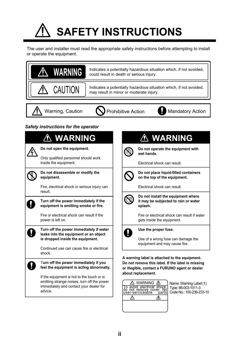
SAFETY INSTRUCTIONS
Do not operate the equipment with
wet hands.
Electrical shock can result.
Do not place liquid-filled containers
on the top of the equipment.
Electrical shock can result.
Do not install the equipment where
it may be subjected to rain or water
splash.
Fire or electrical shock can result if water
gets inside the equipment.
Use the proper fuse.
Use of a wrong fuse can damage the
equipment and may cause fire.
WARNINGIndicates a potentially hazardous situation which, if not avoided,
could result in death or serious injury.
CAUTION Indicates a potentially hazardous situation which, if not avoided,
may result in minor or moderate injury.
Warning, Caution Mandatory Action Prohibitive Action
The user and installer must read the appropriate safety instructions before attempting to install
or operate the equipment.
WARNING
WARNINGDo not open the equipment.
Only qualified personnel should work
inside the equipment.
Do not disassemble or modify the
equipment.
Fire, electrical shock or serious injury can
result.
Turn off the power immediately if the
equipment is emitting smoke or fire.
Fire or electrical shock can result if the
power is left on.
Turn off the power immediately if water
leaks into the equipment or an object
is dropped inside the equipment.
Continued use can cause fire or electrical
shock.
Turn off the power immediately if you
feel the equipment is acting abnormally.
If the equipment is hot to the touch or is
emitting strange noises, turn off the power
immediately and contact your dealer for
advice.
WARNING
Safety instructions for the operator
WARNINGTo avoid electrical shock, do not remove cover. No user-serviceable parts
Name: Warning Label (1)Type: 86-003-1011-3Code No.: 100-236-233-10
A warning label is attached to the equipment.
Do not remove this label. If the label is missing
or illegible, contact a FURUNO agent or dealer
about replacement.
ii
SAFETY INSTRUCTIONS
Standard
compass
Steering
compass
0.95 m 0.60 m
CAUTIONCAUTIONThe transducer cable must be handled
carefully, following the guidelines
below.
• Keep fuels and oils away from the
cable.
• Locate the cable away from chemicals.
• Locate the cable away from locations
where it might be damaged.
Do not apply the power with the
transducer exposed to air.
Damage to the transducer may result.
Observe the following compass safe
distances to prevent interference to a
magnetic compass:
WARNING
WARNINGDo not open the equipment.
Only qualified personnel should work
inside the equipment.
Turn off the power before beginning
the installation.
Fire or electrical shock can result if the
power is left on.
Be sure no water leaks at the transducer
and temperature sensor.
Water leakage can sink the vessel. Also,
confirm that neither the transducer or
sensor will loosen by vibration. The
installer is solely responsible for the
installation.
Confirm that the power supply voltage
is within the rating of this equipment.
Incorrect voltage will damage the equip-
ment and may cause fire.
Safety instructions for the installer
iii
iv
TABLE OF CONTENTS
FOREWORD ....................................................................................................................vSYSTEM CONFIGURATION ..........................................................................................vi
1. MOUNTING ...............................................................................................................11.1 Equipment Lists............................................................................................................. 11.2 Network Sounder .......................................................................................................... 51.3 Transducer .................................................................................................................... 51.4 Optional Speed/Temperature Sensors ST-02MSB, ST-02PSB .................................... 5
1.4.1 Mounting considerations........................................................................................ 51.4.2 Mounting procedure............................................................................................... 6
2. WIRING .....................................................................................................................72.1 Wiring Outline................................................................................................................ 72.2 Transducer Cable.......................................................................................................... 8
3. INITIAL SETTINGS .................................................................................................113.1 Tap Setting.................................................................................................................. 113.2 DIP Switch Setting ...................................................................................................... 123.3 Operation Check ......................................................................................................... 14
4. MAINTENANCE ......................................................................................................154.1 Maintenance................................................................................................................ 154.2 Replacing the Fuse ..................................................................................................... 164.3 Restoring Default Settings .......................................................................................... 16
APPENDIX 1 INSTALLATION OF TEMPERATURE SENSORS..............................AP-1
SPECIFICATIONS .....................................................................................................SP-1
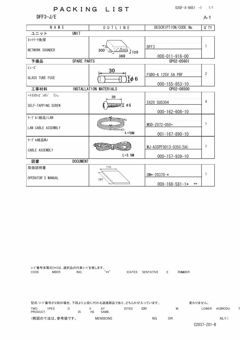
PACKING LIST ............................................................................................................A-1
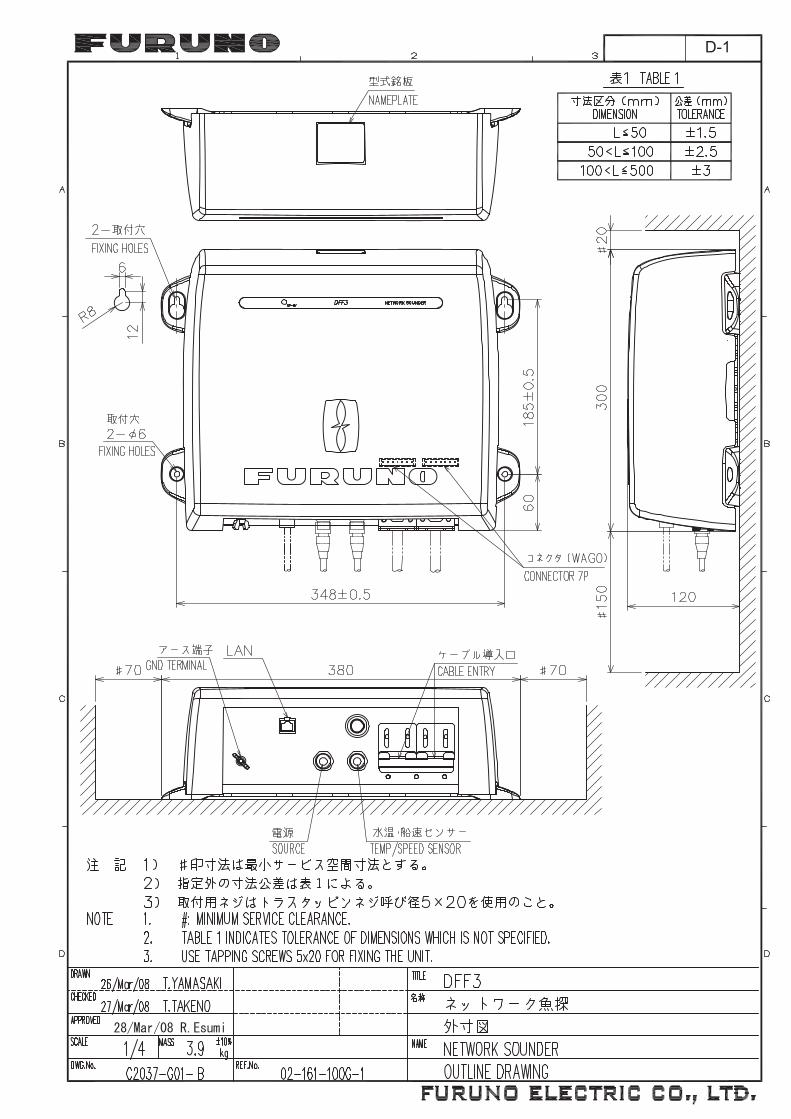
OUTLINE DRAWING ...................................................................................................D-1
INTERCONNECTION DIAGRAM ................................................................................ S-1
v
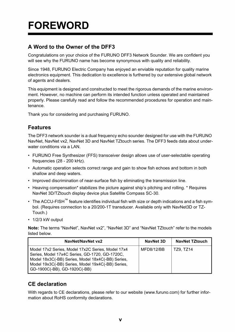
FOREWORD
A Word to the Owner of the DFF3
Congratulations on your choice of the FURUNO DFF3 Network Sounder. We are confident you will see why the FURUNO name has become synonymous with quality and reliability.
Since 1948, FURUNO Electric Company has enjoyed an enviable reputation for quality marine electronics equipment. This dedication to excellence is furthered by our extensive global network of agents and dealers.
This equipment is designed and constructed to meet the rigorous demands of the marine environ-ment. However, no machine can perform its intended function unless operated and maintained properly. Please carefully read and follow the recommended procedures for operation and main-tenance.
Thank you for considering and purchasing FURUNO.
Features
The DFF3 network sounder is a dual frequency echo sounder designed for use with the FURUNO NavNet, NavNet vx2, NavNet 3D and NavNet TZtouch series. The DFF3 feeds data about under-water conditions via a LAN.
• FURUNO Free Synthesizer (FFS) transceiver design allows use of user-selectable operating frequencies (28 - 200 kHz).
• Automatic operation selects correct range and gain to show fish echoes and bottom in both shallow and deep waters.
• Improved discrimination of near-surface fish by eliminating the transmission line.
• Heaving compensation* stabilizes the picture against ship’s pitching and rolling. * Requires NavNet 3D/TZtouch display device plus Satellite Compass SC-30.
• The ACCU-FISH™ feature identifies individual fish with size or depth indications and a fish sym-bol. (Requires connection to a 20/200-1T transducer. Available only with NavNet3D or TZ-Touch.)
• 1/2/3 kW output
Note: The terms “NavNet”, NavNet vx2”, “NavNet 3D” and “NavNet TZtouch” refer to the models listed below.
CE declaration
With regards to CE declarations, please refer to our website (www.furuno.com) for further infor-mation about RoHS conformity declarations.
NavNet/NavNet vx2 NavNet 3D NavNet TZtouch
Model 17x2 Series, Model 17x2C Series, Model 17x4Series, Model 17x4C Series, GD-1720, GD-1720C,Model 18x3C(-BB) Series, Model 18x4C(-BB) Series,Model 19x3C(-BB) Series, Model 19x4C(-BB) Series,GD-1900C(-BB), GD-1920C(-BB)
MFD8/12/BB TZ9, TZ14
vi
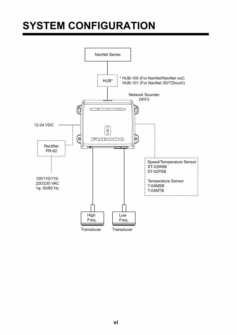
SYSTEM CONFIGURATION
100/110/115/220/230 VAC1φ, 50/60 Hz
Network SounderDFF3
12-24 VDC
LowFreq.
Transducer
HighFreq.
Transducer
RectifierPR-62
Speed/Temperature SensorST-02MSBST-02PSB
Temperature SensorT-04MSBT-04MTB
DFF3 NETWORK SOUNDERST-BY
* HUB-100 (For NavNet/NavNet vx2)HUB-101 (For NavNet 3D/TZtouch)
NavNet Series
HUB*
1. MOUNTING
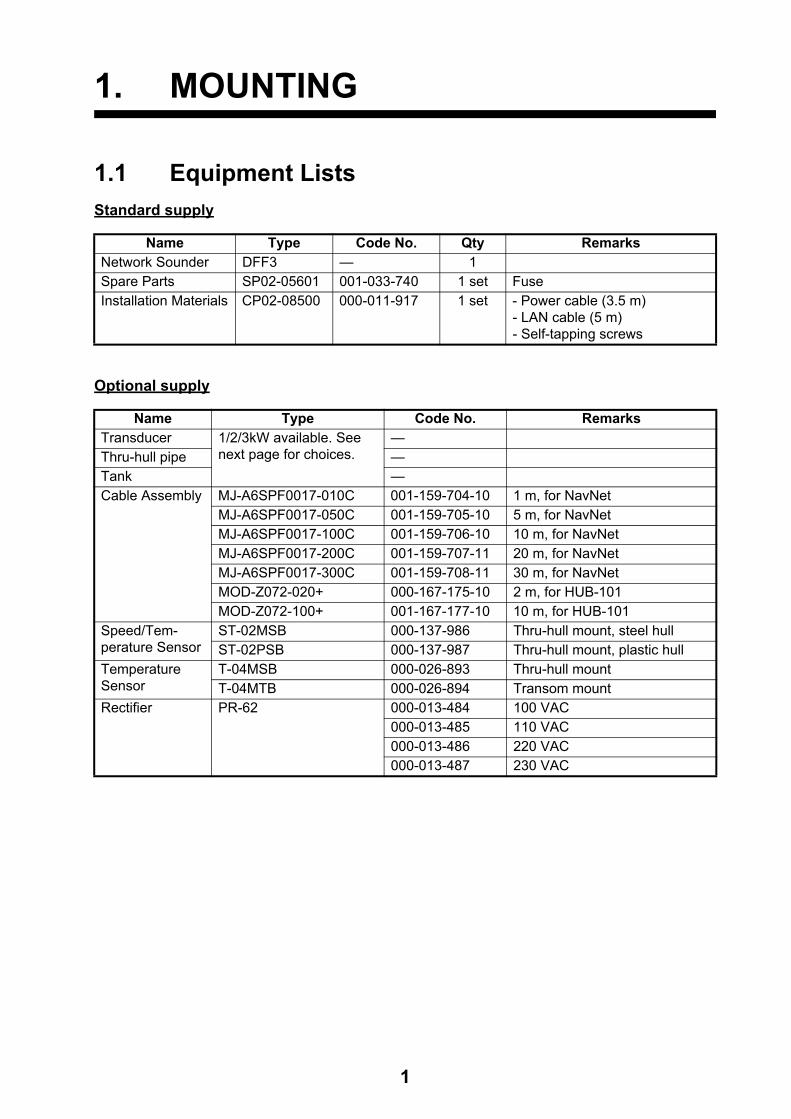
1.1 Equipment Lists
Standard supply
Optional supply
Name Type Code No. Qty RemarksNetwork Sounder DFF3 — 1Spare Parts SP02-05601 001-033-740 1 set FuseInstallation Materials CP02-08500 000-011-917 1 set - Power cable (3.5 m)
- LAN cable (5 m)- Self-tapping screws
Name Type Code No. RemarksTransducer 1/2/3kW available. See
next page for choices.—
Thru-hull pipe —Tank —Cable Assembly MJ-A6SPF0017-010C 001-159-704-10 1 m, for NavNet
MJ-A6SPF0017-050C 001-159-705-10 5 m, for NavNetMJ-A6SPF0017-100C 001-159-706-10 10 m, for NavNetMJ-A6SPF0017-200C 001-159-707-11 20 m, for NavNetMJ-A6SPF0017-300C 001-159-708-11 30 m, for NavNetMOD-Z072-020+ 000-167-175-10 2 m, for HUB-101MOD-Z072-100+ 001-167-177-10 10 m, for HUB-101
Speed/Tem-perature Sensor
ST-02MSB 000-137-986 Thru-hull mount, steel hullST-02PSB 000-137-987 Thru-hull mount, plastic hull
Temperature Sensor
T-04MSB 000-026-893 Thru-hull mountT-04MTB 000-026-894 Transom mount
Rectifier PR-62 000-013-484 100 VAC000-013-485 110 VAC000-013-486 220 VAC000-013-487 230 VAC
1
1. MOUNTING
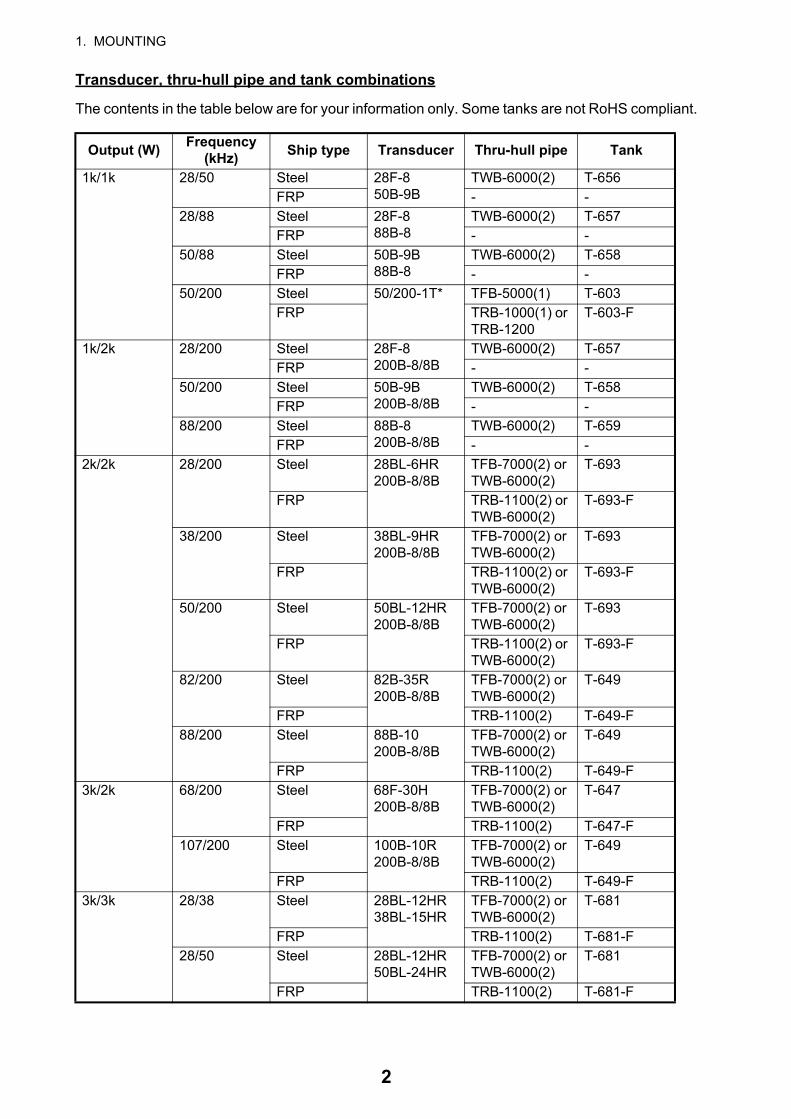
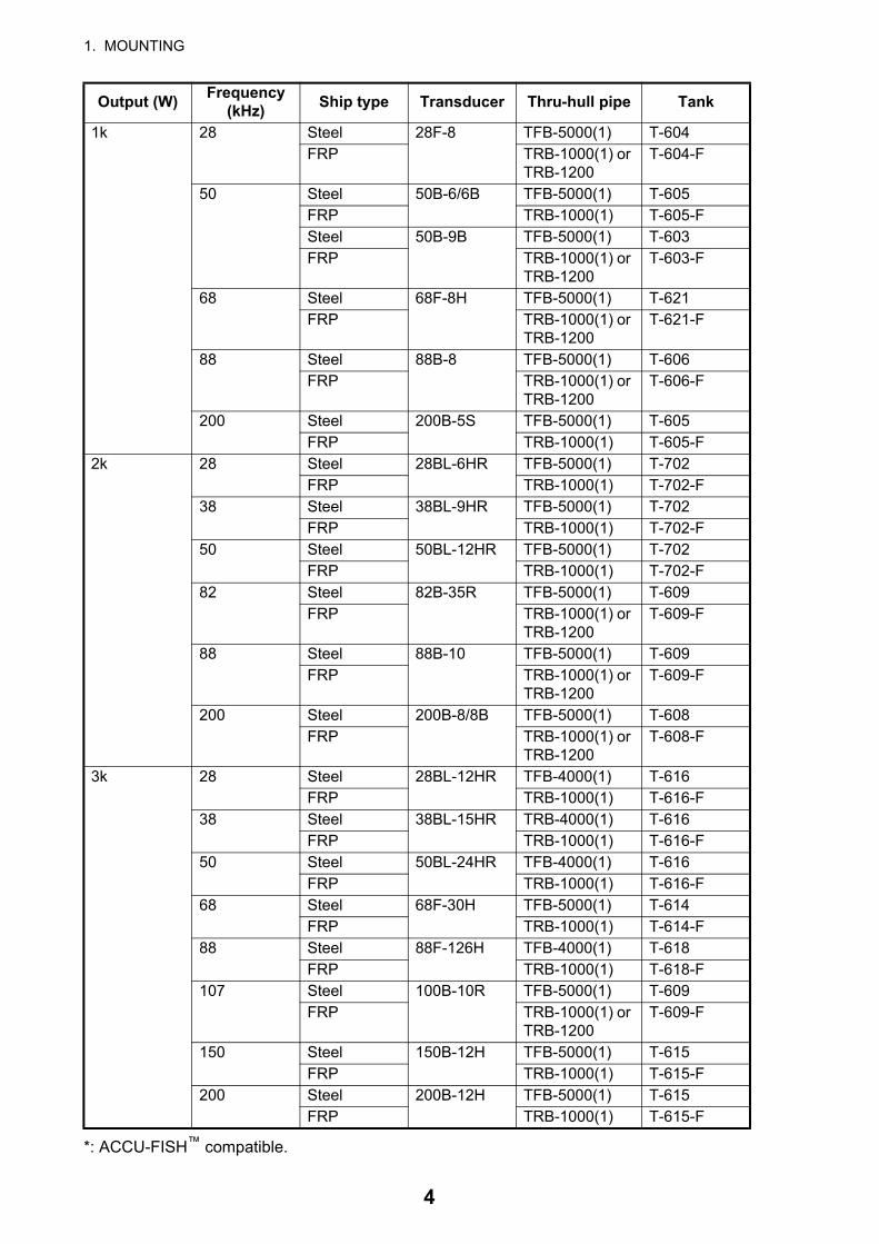
Transducer, thru-hull pipe and tank combinations
The contents in the table below are for your information only. Some tanks are not RoHS compliant.
Output (W)Frequency
(kHz)Ship type Transducer Thru-hull pipe Tank
1k/1k 28/50 Steel 28F-850B-9B
TWB-6000(2) T-656FRP - -
28/88 Steel 28F-888B-8
TWB-6000(2) T-657FRP - -
50/88 Steel 50B-9B88B-8
TWB-6000(2) T-658FRP - -
50/200 Steel 50/200-1T* TFB-5000(1) T-603FRP TRB-1000(1) or
TRB-1200T-603-F
1k/2k 28/200 Steel 28F-8200B-8/8B
TWB-6000(2) T-657FRP - -
50/200 Steel 50B-9B200B-8/8B
TWB-6000(2) T-658FRP - -
88/200 Steel 88B-8200B-8/8B
TWB-6000(2) T-659FRP - -
2k/2k 28/200 Steel 28BL-6HR200B-8/8B
TFB-7000(2) or TWB-6000(2)
T-693
FRP TRB-1100(2) or TWB-6000(2)
T-693-F
38/200 Steel 38BL-9HR200B-8/8B
TFB-7000(2) or TWB-6000(2)
T-693
FRP TRB-1100(2) or TWB-6000(2)
T-693-F
50/200 Steel 50BL-12HR200B-8/8B
TFB-7000(2) or TWB-6000(2)
T-693
FRP TRB-1100(2) or TWB-6000(2)
T-693-F
82/200 Steel 82B-35R200B-8/8B
TFB-7000(2) or TWB-6000(2)
T-649
FRP TRB-1100(2) T-649-F88/200 Steel 88B-10
200B-8/8BTFB-7000(2) or TWB-6000(2)
T-649
FRP TRB-1100(2) T-649-F3k/2k 68/200 Steel 68F-30H
200B-8/8BTFB-7000(2) or TWB-6000(2)
T-647
FRP TRB-1100(2) T-647-F107/200 Steel 100B-10R
200B-8/8BTFB-7000(2) or TWB-6000(2)
T-649
FRP TRB-1100(2) T-649-F3k/3k 28/38 Steel 28BL-12HR
38BL-15HRTFB-7000(2) or TWB-6000(2)
T-681
FRP TRB-1100(2) T-681-F28/50 Steel 28BL-12HR
50BL-24HRTFB-7000(2) or TWB-6000(2)
T-681
FRP TRB-1100(2) T-681-F
2
1. MOUNTING
3k/3k(con’t)
28/88 Steel 28BL-12HR88F-126H
TFB-7000(2) or TWB-6000(2)
T-682
FRP TRB-1100(2) T-682-F28/150 Steel 28BL-12HR
150B-12HTFB-7000(2) or TWB-6000(2)
T-683
FRP TRB-1100(2) T-683-F28/200 Steel 28BL-12HR
200B-12HTFB-7000(2) or TWB-6000(2)
T-683
FRP TRB-1100(2) T-683-F38/50 Steel 38BL-15HR
50BL-24HRTFB-7000(2) or TWB-6000(2)
T-681
FRP TRB-1100(2) T-681-F38/88 Steel 38BL-15HR
88F-126HTFB-7000(2) or TWB-6000(2)
T-682
FRP TRB-1100(2) T-682-F38/150 Steel 38BL-15HR
150B-12HTFB-7000(2) or TWB-6000(2)
T-683
FRP TRB-1100(2) T-683-F38/200 Steel 38BL-15HR
200B-12HTFB-7000(2) or TWB-6000(2)
T-683
FRP TRB-1100(2) T-683-F50/88 Steel 50BL-24HR
88F-126HTFB-7000(2) or TWB-6000(2)
T-682
FRP TRB-1100(2) T-682-F50/150 Steel 50BL-24HR
150B-12HTFB-7000(2) or TWB-6000(2)
T-683
FRP TRB-1100(2) T-683-F50/200 Steel 50BL-24HR
200B-12HTFB-7000(2) or TWB-6000(2)
T-683
FRP TRB-1100(2) T-683-F68/150 Steel 68F-30H
150B-12HTFB-7000(2) or TWB-6000(2)
T-646
FRP TRB-1100(2) T-646-F68/200 Steel 68F-30H
200B-12HTFB-7000(2) or TWB-6000(2)
T-646
FRP TRB-1100(2) T-646-F88/150 Steel 88F-126H
150B-12HTFB-7000(2) or TWB-6000(2)
T-685
FRP TRB-1100(2) T-685-F88/200 Steel 88F-126H
200B-12HTFB-7000(2) or TWB-6000(2)
T-685
FRP TRB-1100(2) T-685-F
Output (W)Frequency
(kHz)Ship type Transducer Thru-hull pipe Tank
3
1. MOUNTING
*: ACCU-FISH™ compatible.
1k 28 Steel 28F-8 TFB-5000(1) T-604FRP TRB-1000(1) or
TRB-1200T-604-F
50 Steel 50B-6/6B TFB-5000(1) T-605FRP TRB-1000(1) T-605-FSteel 50B-9B TFB-5000(1) T-603FRP TRB-1000(1) or
TRB-1200T-603-F
68 Steel 68F-8H TFB-5000(1) T-621FRP TRB-1000(1) or
TRB-1200T-621-F
88 Steel 88B-8 TFB-5000(1) T-606FRP TRB-1000(1) or
TRB-1200T-606-F
200 Steel 200B-5S TFB-5000(1) T-605FRP TRB-1000(1) T-605-F
2k 28 Steel 28BL-6HR TFB-5000(1) T-702FRP TRB-1000(1) T-702-F
38 Steel 38BL-9HR TFB-5000(1) T-702FRP TRB-1000(1) T-702-F
50 Steel 50BL-12HR TFB-5000(1) T-702FRP TRB-1000(1) T-702-F
82 Steel 82B-35R TFB-5000(1) T-609FRP TRB-1000(1) or
TRB-1200T-609-F
88 Steel 88B-10 TFB-5000(1) T-609FRP TRB-1000(1) or
TRB-1200T-609-F
200 Steel 200B-8/8B TFB-5000(1) T-608FRP TRB-1000(1) or
TRB-1200T-608-F
3k 28 Steel 28BL-12HR TFB-4000(1) T-616FRP TRB-1000(1) T-616-F
38 Steel 38BL-15HR TRB-4000(1) T-616FRP TRB-1000(1) T-616-F
50 Steel 50BL-24HR TFB-4000(1) T-616FRP TRB-1000(1) T-616-F
68 Steel 68F-30H TFB-5000(1) T-614FRP TRB-1000(1) T-614-F
88 Steel 88F-126H TFB-4000(1) T-618FRP TRB-1000(1) T-618-F
107 Steel 100B-10R TFB-5000(1) T-609FRP TRB-1000(1) or
TRB-1200T-609-F
150 Steel 150B-12H TFB-5000(1) T-615FRP TRB-1000(1) T-615-F
200 Steel 200B-12H TFB-5000(1) T-615FRP TRB-1000(1) T-615-F
Output (W)Frequency
(kHz)Ship type Transducer Thru-hull pipe Tank
4
1. MOUNTING
1.2 Network SounderThe network sounder can be installed on a desktop, deck or on a bulkhead. When selecting a mounting location for the network sounder, keep the following in mind:
• The temperature and humidity at the mounting site should be moderate and stable.
• Locate the unit away from exhaust pipes and vents.
• The mounting location should be well ventilated.
• Mount the unit where shock and vibration are minimal.
• Keep the unit away from electromagnetic field-generating equipment such as motors and gen-erators.
• Leave slack in cables for maintenance and servicing ease.
• A magnetic compass will be affected if the network sounder is placed too close to it. Observe the compass safe distances noted in the safety instructions to prevent disturbance to the mag-netic compass.
Fasten the network sounder to the mounting location with four self-tapping screws (5×20), refer-ring to the outline drawing at the back of this manual for mounting dimensions.
1.3 TransducerThe performance of the echo sounder largely depends upon the transducer position. Select a place least affected by air bubbles since turbulence blocks the sounding path. Further, select a place least influenced by engine noise. It is known that air bubbles are fewest at the place where the bow first falls and the next wave rises, at usual cruising speed.
Note: The face of the transducer must be facing the sea bottom in normal cruising trim of the boat.
1.4 Optional Speed/Temperature SensorsST-02MSB, ST-02PSB
1.4.1 Mounting considerations
• Select a mid-boat flat position. The sensor does not have to be installed perfectly perpendicular. However, the sensor must not be damaged in dry-docking operation.
• Select a place apart from equipment generating heat.
• Select a place in the forward direction viewing from the drain hole, to allow for circulation of cool-ing water.
• Select a place free from vibration.
• Do not install near the transducer of an echo sounder, to prevent interference to the echo sounder.
5
1. MOUNTING
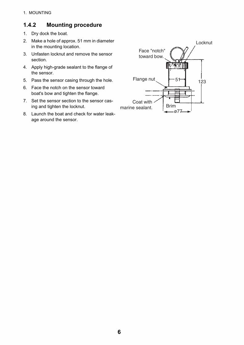
1.4.2 Mounting procedure
1. Dry dock the boat.
2. Make a hole of approx. 51 mm in diameter in the mounting location.
3. Unfasten locknut and remove the sensor section.
4. Apply high-grade sealant to the flange of the sensor.
5. Pass the sensor casing through the hole.
6. Face the notch on the sensor toward boat's bow and tighten the flange.
7. Set the sensor section to the sensor cas-ing and tighten the locknut.
8. Launch the boat and check for water leak-age around the sensor.
Locknut
123
Face "notch"toward bow.
Flange nut
Coat withmarine sealant.
51
Brimø77
6
2. WIRING
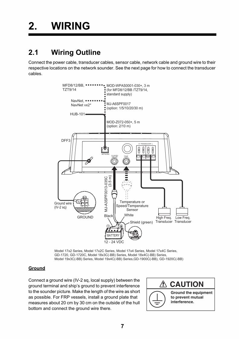
2.1 Wiring OutlineConnect the power cable, transducer cables, sensor cable, network cable and ground wire to their respective locations on the network sounder. See the next page for how to connect the transducer cables.
Ground
Connect a ground wire (IV-2 sq, local supply) between the ground terminal and ship’s ground to prevent interference to the sounder picture. Make the length of the wire as short as possible. For FRP vessels, install a ground plate that measures about 20 cm by 30 cm on the outside of the hull bottom and connect the ground wire there.
GROUND
MOD-Z072-050+, 5 m(option: 2/10 m)
DFF3
Ground wire(IV-2 sq)
BATTERY
WhiteBlack
Shield (green)
12 - 24 VDC
MJ-
A3S
PF0
013-
035C
(3
.5 m
)
High Freq.Transducer
Low Freq.Transducer
HUB-101
NavNet,NavNet vx2* MJ-A6SPF0017
(option: 1/5/10/20/30 m)
Temperature orSpeed/Temperature
Sensor
NETWORK12-24VDC2.8-1.4A TEMP
H TRANSDUCER L
MFD8/12/BB,TZT9/14
MOD-WPAS0001-030+, 3 m (for MFD8/12/BB /TZT9/14,standard supply)
Model 17x2 Series, Model 17x2C Series, Model 17x4 Series, Model 17x4C Series, GD-1720, GD-1720C, Model 18x3C(-BB) Series, Model 18x4C(-BB) Series,Model 19x3C(-BB) Series, Model 19x4C(-BB) Series,GD-1900C(-BB), GD-1920C(-BB)
Ground the equipmentto prevent mutualinterference.
CAUTION
7
2. WIRING
Multiple network sounders
Two DFF3 units may be connected by using HUB-101.
2.2 Transducer Cable
TD-ID transducer cable
• TD-ID transducer cannot be used with NavNet, NavNet vx2.
• TD-ID transducer cannot be used with non-TD-ID transducer.
• Connect single TD-ID transducer to low frequency WAGO connector, regardless of actual fre-quency.
Cable fabrication
Fabricate the transducer cable as shown below. Separate the transducer cable well away from other electric cables to prevent interference to the sounder. This is especially important in the case of power cables from televisions and monitors.
DFF3 Main UnitNavNet
Display UnitHUB-101
NavNet Series
*2
*2
*1
*1 = One NavNet series radar and two NavNet display units may be connected to HUB-101.*2 = MOD-Z072-050+, 5 m (2/10 m: optional supply)*3 = Connect to NET KP to get best performance. Either J24 or J25 can be used but connect to same number.*4 = If an external KP (Keying Pulse) is required, ask a FURUNO dealer.
Optional SupplyLocal Supply
NETWORK
J24
J24
J23
External KP*4
Standard Supply
DFF3 Main Unit
02P6358(Main Board)
02P6358(Main Board)
J25
J25
NETWORK
LAN PortConnector (On the main board )NET KP *3
Braided shield
Vinyl tape
Sheath
Draw out braided shield and wrap it around sheath.
Clamp this part with cable clamp.
Extract cores from here and cut inner materials.
6
Approx. 100
20
8
2. WIRING
Cable connection
After fabricating the transducer cable, connect the transducer cables to the equipment with WAGO connectors.
1. Open the cover: Grasp the cover at two sides, spread cover slightly and lift.
2. Unfasten six screws to remove the shield cover.
3. Detach the two WAGO connectors (low and high frequency) inside the equipment.
4. Connect the transducer cable to the WAGO connector, following the instructions in the figure below and the interconnection diagram. (The opener for the WAGO connector is attached in-side the equipment. See the figure above.)
5. Unfasten the two screws labeled Screw A in the figure below.
6. Loosen the two screws labeled Screw B and slide cable clamp upward.
WAGO connector
(Low frequency)
WAGO connector
(High frequency)
Opener for WAGO connector
is here.
1. Twist conductors.
2. Insert opener as directed and press it down.
3. Insert core to hole.
4. Release opener.
5. Pull the core to make sure it is correctly inserted.
Opener (attached inside the equipment)
Core
Twist.
Push
Screw A
Screw B
Cable
clamp
Clamping
plate
9
2. WIRING
7. Pass the transducer cables through the cable entrance and connect their WAGO connectors to respective terminals inside the equipment.
8. Slide the cable clamp downward and tighten screws B and A in that order to fasten the cable clamp.
Transducer cable
10
3. INITIAL SETTINGS
3.1 Tap SettingThis equipment is preprogrammed for use with certain transducers. A jumper wire inside the equipment is set according to transducer model. Check the jumper wire setting instructions on the sticker attached to the chassis. Use the opener attached inside the unit to set the jumper wire. One end of the jumper wire is connected to COMMON; connect the other end to A - E in the jumper block as applicable.
For transducers not programmed, for example, Airmar make TD-ID transducer, consult aFURUNO agent or dealer for advice.
Note 1: For NavNet, the tap settings shown on the NETWORK SOUNDER SETUP are different from actual ones. Therefore, follow the instructions on the sticker inside the equipment.
Note 2: For transducers 50/200-1T, use the tap settings for 50/200-1T (50: Tap B, 200: Tap C).
WARNINGDo not open the equipment
unless totally familiar with
electrical circuits.
Only qualified personnel
should work inside the
equipment.
Tap setting plug
(High freq.)Tap setting plug
(Low freq.)
EDCBA EDCBA
High Freq. Low Freq.
Tap Setting LED
B ACommon
Jumper wire Set in appropriate slot
according to sticker.
E D C
11
3. INITIAL SETTINGS
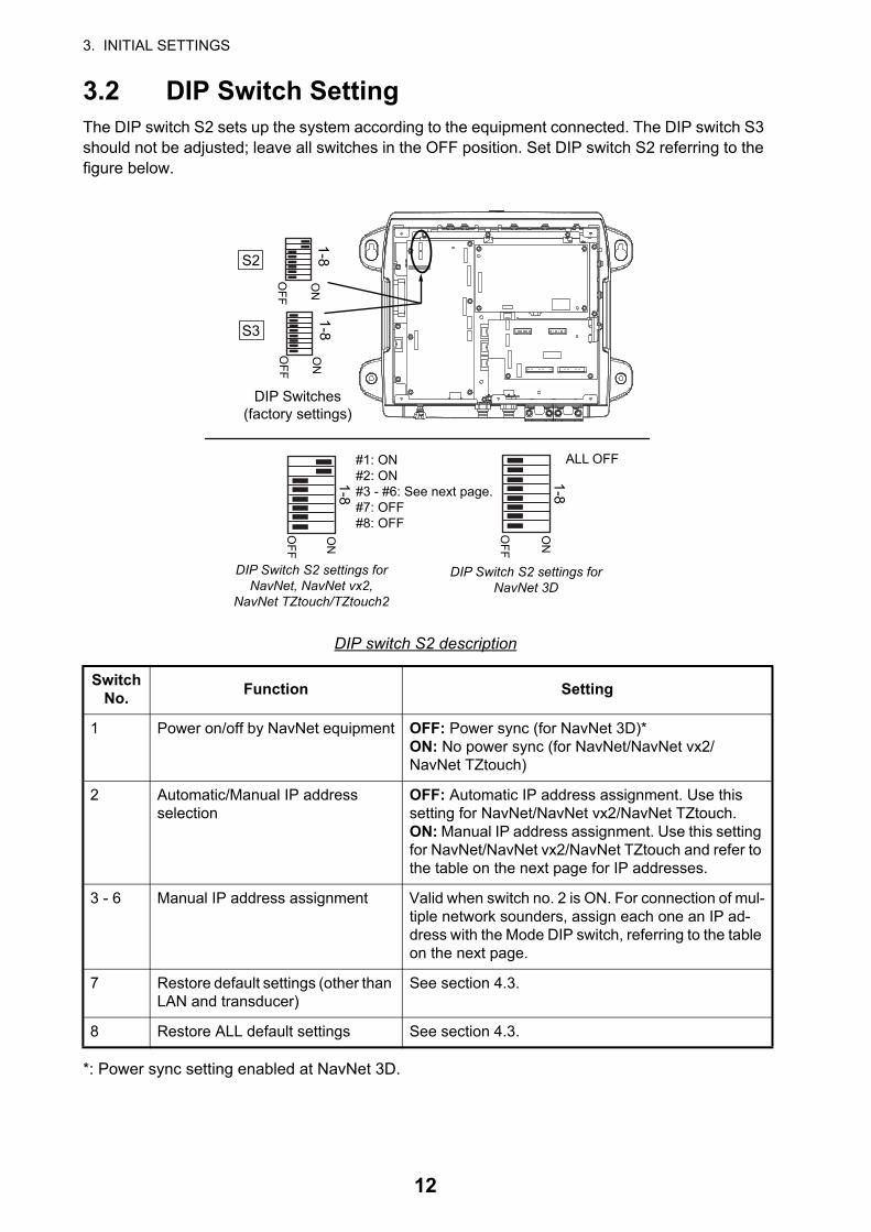
3.2 DIP Switch SettingThe DIP switch S2 sets up the system according to the equipment connected. The DIP switch S3 should not be adjusted; leave all switches in the OFF position. Set DIP switch S2 referring to the figure below.
DIP switch S2 description
*: Power sync setting enabled at NavNet 3D.
Switch No.
Function Setting
1 Power on/off by NavNet equipment OFF: Power sync (for NavNet 3D)*ON: No power sync (for NavNet/NavNet vx2/NavNet TZtouch)
2 Automatic/Manual IP addressselection
OFF: Automatic IP address assignment. Use this setting for NavNet/NavNet vx2/NavNet TZtouch.ON: Manual IP address assignment. Use this setting for NavNet/NavNet vx2/NavNet TZtouch and refer to the table on the next page for IP addresses.
3 - 6 Manual IP address assignment Valid when switch no. 2 is ON. For connection of mul-tiple network sounders, assign each one an IP ad-dress with the Mode DIP switch, referring to the table on the next page.
7 Restore default settings (other than LAN and transducer)
See section 4.3.
8 Restore ALL default settings See section 4.3.
DIP Switches(factory settings)
1-8O
N
OFF
S2
S3
1-8O
N
OFF
ON
OFF
1-8
#1: ON #2: ON #3 - #6: See next page.#7: OFF#8: OFF
ON
OFF
1-8
ALL OFF
DIP Switch S2 settings for NavNet, NavNet vx2,
NavNet TZtouch/TZtouch2
DIP Switch S2 settings forNavNet 3D
12
3. INITIAL SETTINGS
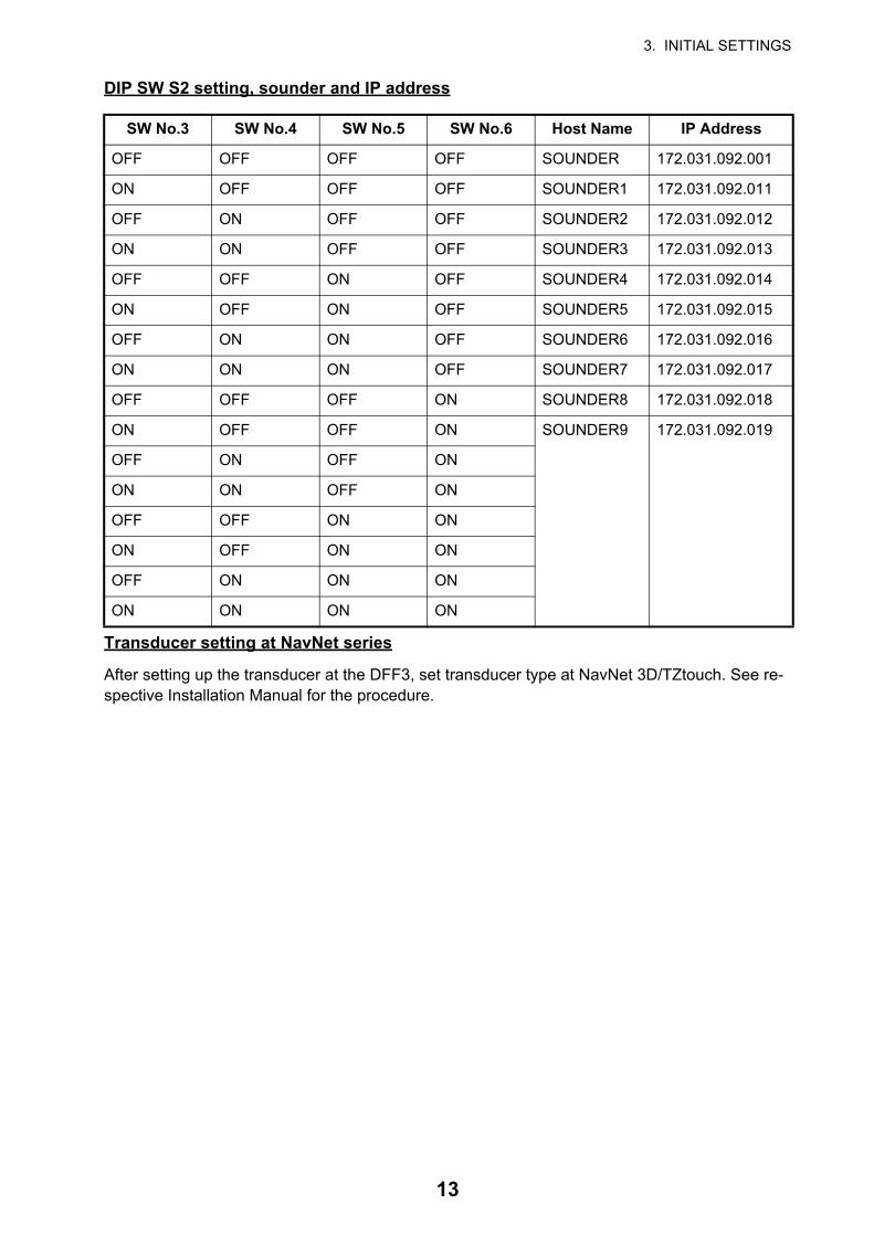
DIP SW S2 setting, sounder and IP address
Transducer setting at NavNet series
After setting up the transducer at the DFF3, set transducer type at NavNet 3D/TZtouch. See re-spective Installation Manual for the procedure.
SW No.3 SW No.4 SW No.5 SW No.6 Host Name IP Address
OFF OFF OFF OFF SOUNDER 172.031.092.001
ON OFF OFF OFF SOUNDER1 172.031.092.011
OFF ON OFF OFF SOUNDER2 172.031.092.012
ON ON OFF OFF SOUNDER3 172.031.092.013
OFF OFF ON OFF SOUNDER4 172.031.092.014
ON OFF ON OFF SOUNDER5 172.031.092.015
OFF ON ON OFF SOUNDER6 172.031.092.016
ON ON ON OFF SOUNDER7 172.031.092.017
OFF OFF OFF ON SOUNDER8 172.031.092.018
ON OFF OFF ON SOUNDER9 172.031.092.019
OFF ON OFF ON
ON ON OFF ON
OFF OFF ON ON
ON OFF ON ON
OFF ON ON ON
ON ON ON ON
13
3. INITIAL SETTINGS
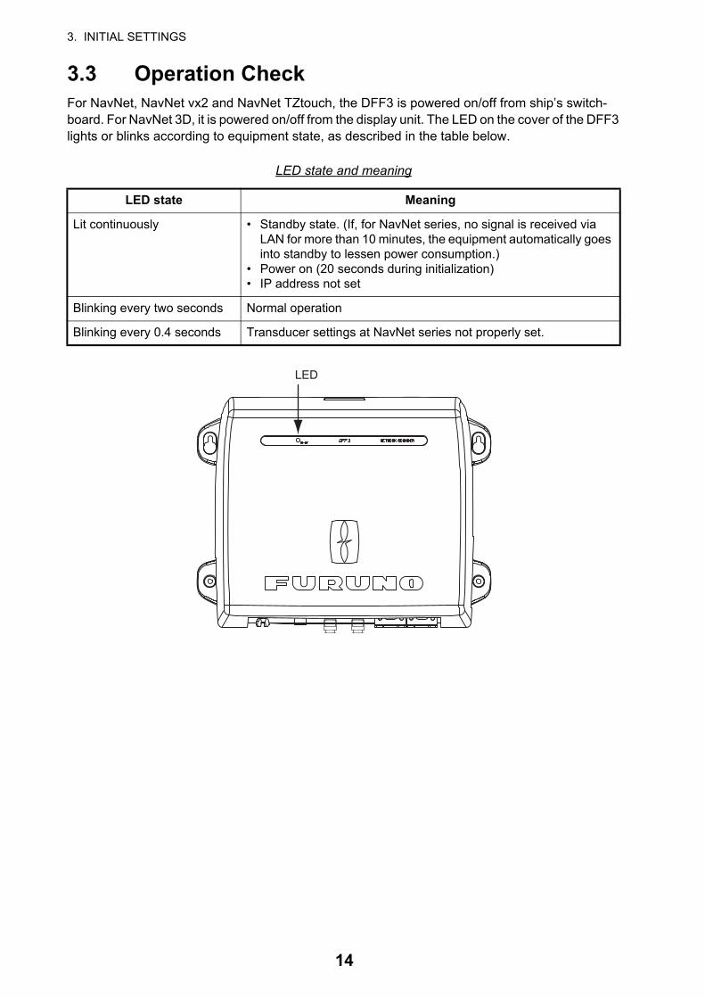
3.3 Operation CheckFor NavNet, NavNet vx2 and NavNet TZtouch, the DFF3 is powered on/off from ship’s switch-board. For NavNet 3D, it is powered on/off from the display unit. The LED on the cover of the DFF3 lights or blinks according to equipment state, as described in the table below.
LED state and meaning
LED state Meaning
Lit continuously • Standby state. (If, for NavNet series, no signal is received via LAN for more than 10 minutes, the equipment automatically goes into standby to lessen power consumption.)
• Power on (20 seconds during initialization)• IP address not set
Blinking every two seconds Normal operation
Blinking every 0.4 seconds Transducer settings at NavNet series not properly set.
LED
14
4. MAINTENANCE
4.1 MaintenanceRegular maintenance is essential for good performance. Check the items listed in the table below at the suggested interval to help keep your equipment in good shape for years to come.
Item Check point, action Check interval
Transducer cables Check that cables are tightly fastened and are not damaged. Refasten if necessary. Replace if dam-aged.
Once a month
Power cable, sensor ca-ble
Check that these cables are tightly fastened and not damaged. Refasten if necessary. Replace if damaged.
Once a month
Ground Check for corrosion. Clean if necessary. Once a month
Power supply voltage Check voltage. If out of rating correct problem. Once a month
Cleaning the network sounder’s cabinet
Dust or dirt on the cabinet may be removed with a dry cloth. Do not use chemical-based cleaners to clean the cabinet; they can remove markings and damage the cabinet.
Once a month
Transducer Marine life on the transducer face will result in a gradual decrease in sensitivity. Check the trans-ducer face for cleanliness each time the boat is dry-docked. Carefully remove any marine life with a piece of wood or fine-grade sandpaper.
When vessel is dry-docked
WARNINGELECTRICAL SHOCK HAZARDDo not open the equipment.
Only qualified personnelshould work inside theequipment.
NOTICEDo not apply paint, anti-corrosivesealant or contact spray to coatingor plastic parts of the equipment.
Those items contain organic solventsthat can damage coating and plasticparts, especially plastic connectors.
15
4. MAINTENANCE
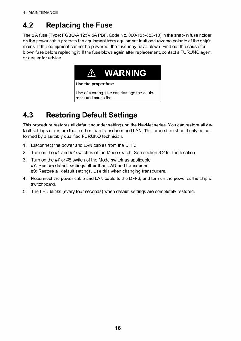
4.2 Replacing the FuseThe 5 A fuse (Type: FGBO-A 125V 5A PBF, Code No. 000-155-853-10) in the snap-in fuse holder on the power cable protects the equipment from equipment fault and reverse polarity of the ship's mains. If the equipment cannot be powered, the fuse may have blown. Find out the cause for blown fuse before replacing it. If the fuse blows again after replacement, contact a FURUNO agent or dealer for advice.
4.3 Restoring Default SettingsThis procedure restores all default sounder settings on the NavNet series. You can restore all de-fault settings or restore those other than transducer and LAN. This procedure should only be per-formed by a suitably qualified FURUNO technician.
1. Disconnect the power and LAN cables from the DFF3.
2. Turn on the #1 and #2 switches of the Mode switch. See section 3.2 for the location.
3. Turn on the #7 or #8 switch of the Mode switch as applicable.#7: Restore default settings other than LAN and transducer.#8: Restore all default settings. Use this when changing transducers.
4. Reconnect the power cable and LAN cable to the DFF3, and turn on the power at the ship’s switchboard.
5. The LED blinks (every four seconds) when default settings are completely restored.
WARNINGUse the proper fuse.
Use of a wrong fuse can damage the equip-ment and cause fire.
16
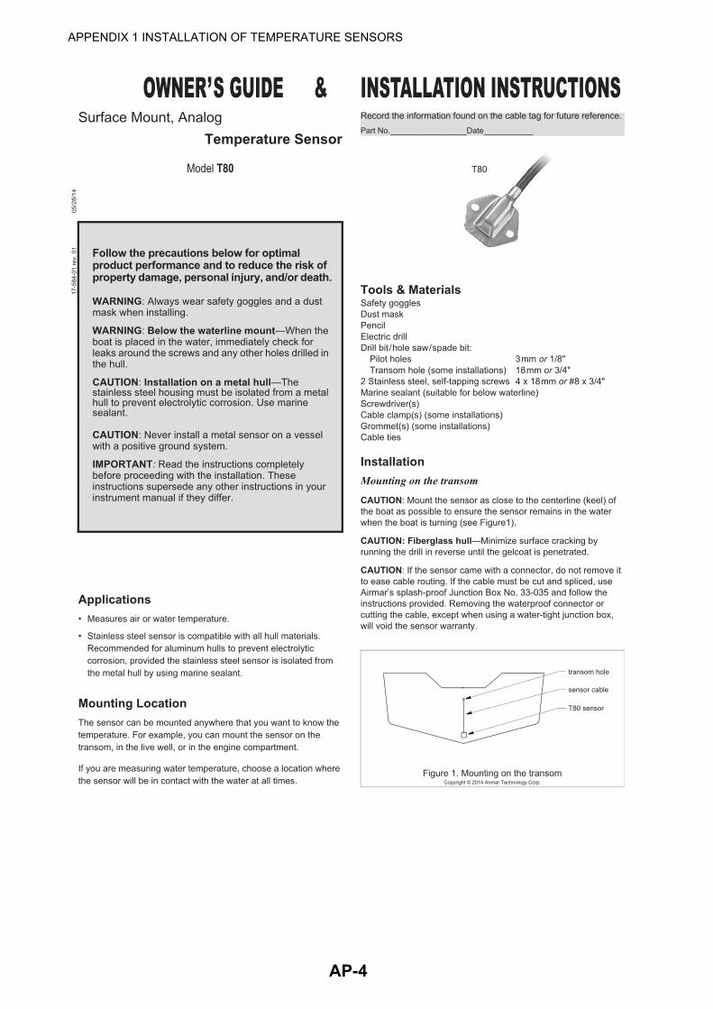
APPENDIX 1 INSTALLATION OFTEMPERATURE SENSORS
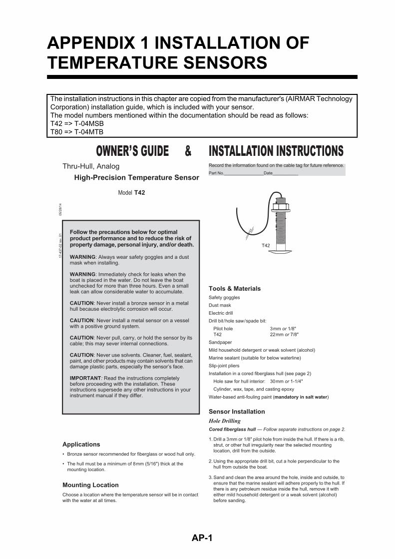
The installation instructions in this chapter are copied from the manufacturer's (AIRMAR Technology Corporation) installation guide, which is included with your sensor.The model numbers mentioned within the documentation should be read as follows:T42 => T-04MSBT80 => T-04MTB
AP-1
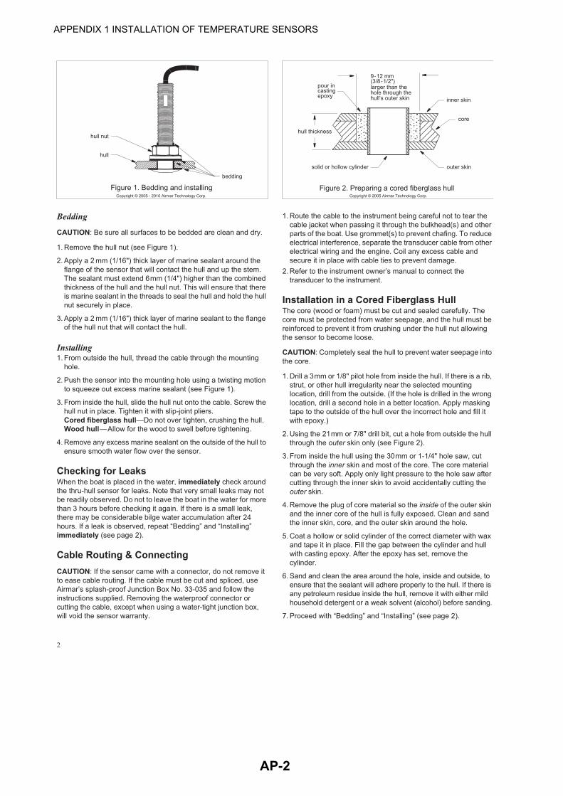
APPENDIX 1 INSTALLATION OF TEMPERATURE SENSORS
AP-2
APPENDIX 1 INSTALLATION OF TEMPERATURE SENSORS
AP-3
APPENDIX 1 INSTALLATION OF TEMPERATURE SENSORS
AP-4
APPENDIX 1 INSTALLATION OF TEMPERATURE SENSORS
AP-5
FURUNO DFF3
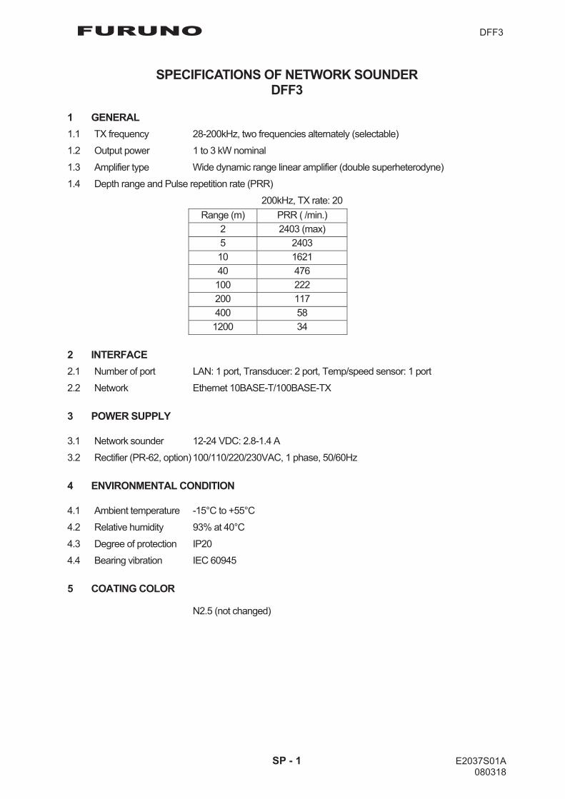
SPECIFICATIONS OF NETWORK SOUNDER DFF3
1 GENERAL 1.1 TX frequency 28-200kHz, two frequencies alternately (selectable)
1.2 Output power 1 to 3 kW nominal
1.3 Amplifier type Wide dynamic range linear amplifier (double superheterodyne) 1.4 Depth range and Pulse repetition rate (PRR)
200kHz, TX rate: 20 Range (m) PRR ( /min.)
2 2403 (max)5 240310 162140 476100 222200 117400 581200 34
2 INTERFACE 2.1 Number of port LAN: 1 port, Transducer: 2 port, Temp/speed sensor: 1 port
2.2 Network Ethernet 10BASE-T/100BASE-TX
3 POWER SUPPLY
3.1 Network sounder 12-24 VDC: 2.8-1.4 A
3.2 Rectifier (PR-62, option) 100/110/220/230VAC, 1 phase, 50/60Hz
4 ENVIRONMENTAL CONDITION
4.1 Ambient temperature -15°C to +55°C
4.2 Relative humidity 93% at 40°C
4.3 Degree of protection IP20 4.4 Bearing vibration IEC 60945
5 COATING COLOR
N2.5 (not changed)
SP - 1 E2037S01A 080318
A-1
D-1
S-1
26/N
ov/2
015
H.M
AK
I
FURUNO Worldwide Warranty for Pleasure Boats (Except North America)
This warranty is valid for products manufactured by Furuno Electric Co. (hereafter FURUNO) and installed on a pleasure boat. Any web based purchases that are imported into other countries by anyone other than a FURUNO certified dealer may not comply with local standards. FURUNO strongly recommends against importing these products from international websites as the imported product may not work correctly and may interfere with other electronic devices. The imported product may also be in breach of the local laws and mandated technical requirements. Products imported into other countries as described previously shall not be eligible for local warranty service. For products purchased outside of your country please contact the national distributor of Furuno products in the country where purchased. This warranty is in addition to the customer´s statutory legal rights.
1. Terms and Conditions of Warranty
FURUNO guarantees that each new FURUNO product is the result of quality materials and workmanship. The warranty is valid for a period of 2 years (24 months) from the date of the invoice, or the date of commissioning of the product by the installing certified dealer.
2. FURUNO Standard Warranty The FURUNO standard warranty covers spare parts and labour costs associated with a warranty claim, provided that the product is returned to a FURUNO national distributor by prepaid carrier. The FURUNO standard warranty includes:
Repair at a FURUNO national distributor All spare parts for the repair Cost for economical shipment to customer
3. FURUNO Onboard Warranty
If the product was installed/commissioned and registered by a certified FURUNO dealer, the customer has the right to the onboard warranty. The FURUNO onboard warranty includes
• Free shipping of the necessary parts • Labour: Normal working hours only • Travel time: Up to a maximum of two (2) hours • Travel distance: Up to a maximum of one hundred
and sixty (160) KM by car for the complete journey
4. Warranty Registration For the Standard Warranty - presentation of product with serial number (8 digits serial number, 1234-5678) is sufficient. Otherwise, the invoice with serial number, name and stamp of the dealer and date of purchase is shown. For the Onboard Warranty your FURUNO certified dealer will take care of all registrations.
5. Warranty Claims For the Standard Warranty - simply send the defective product together with the invoice to a FURUNO national distributor. For the Onboard Warranty – contact a FURUNO national distributor or a certified dealer. Give the product´s serial number and describe the problem as accurately as possible.
Warranty repairs carried out by companies/persons other than a FURUNO national distributor or a certified dealer is not covered by this warranty.
6. Warranty Limitations
When a claim is made, FURUNO has a right to choose whether to repair the product or replace it. The FURUNO warranty is only valid if the product was correctly installed and used. Therefore, it is necessary for the customer to comply with the instructions in the handbook. Problems which result from not complying with the instruction manual are not covered by the warranty. FURUNO is not liable for any damage caused to the vessel by using a FURUNO product. The following are excluded from this warranty: a. Second-hand product b. Underwater unit such as transducer and hull unit c. Routine maintenance, alignment and calibration
services. d. Replacement of consumable parts such as fuses,
lamps, recording papers, drive belts, cables, protective covers and batteries.
d. Magnetron and MIC with more than 1000 transmitting
hours or older than 12 months, whichever comes first. e. Costs associated with the replacement of a transducer
(e.g. Crane, docking or diver etc.).
f. Sea trial, test and evaluation or other demonstrations. g. Products repaired or altered by anyone other than the
FURUNO national distributor or an authorized dealer. h. Products on which the serial number is altered,
defaced or removed. i. Problems resulting from an accident, negligence,
misuse, improper installation, vandalism or water penetration.
j. Damage resulting from a force majeure or other natural
catastrophe or calamity. k. Damage from shipping or transit. l. Software updates, except when deemed necessary
and warrantable by FURUNO. m. Overtime, extra labour outside of normal hours such as
weekend/holiday, and travel costs above the 160 KM allowance
n. Operator familiarization and orientation. FURUNO Electric Company, March 1, 2011
FURUNO Warranty for North America
FURUNO U.S.A., Limited Warranty provides a twenty-four (24) months LABOR and twenty-four (24) months PARTS warranty on products from the date of installation or purchase by the original owner. Products or components that are represented as being waterproof are guaranteed to be waterproof only for, and within the limits, of the warranty period stated above. The warranty start date may not exceed eighteen (18) months from the original date of purchase by dealer from Furuno USA and applies to new equipment installed and operated in accordance with Furuno USA’s published instructions. Magnetrons and Microwave devices will be warranted for a period of 12 months from date of original equipment installation. Furuno U.S.A., Inc. warrants each new product to be of sound material and workmanship and through its authorized dealer will exchange any parts proven to be defective in material or workmanship under normal use at no charge for a period of 24 months from the date of installation or purchase. Furuno U.S.A., Inc., through an authorized Furuno dealer will provide labor at no cost to replace defective parts, exclusive of routine maintenance or normal adjustments, for a period of 24 months from installation date provided the work is done by Furuno U.S.A., Inc. or an AUTHORIZED Furuno dealer during normal shop hours and within a radius of 50 miles of the shop location. A suitable proof of purchase showing date of purchase, or installation certification must be available to Furuno U.S.A., Inc., or its authorized dealer at the time of request for warranty service. This warranty is valid for installation of products manufactured by Furuno Electric Co. (hereafter FURUNO). Any purchases from brick and mortar or web-based resellers that are imported into other countries by anyone other than a FURUNO certified dealer, agent or subsidiary may not comply with local standards. FURUNO strongly recommends against importing these products from international websites or other resellers, as the imported product may not work correctly and may interfere with other electronic devices. The imported product may also be in breach of the local laws and mandated technical requirements. Products imported into other countries, as described previously, shall not be eligible for local warranty service. For products purchased outside of your country please contact the national distributor of Furuno products in the country where purchased.
WARRANTY REGISTRATION AND INFORMATION To register your product for warranty, as well as see the complete warranty guidelines and limitations, please visit www.furunousa.com and click on “Support”. In order to expedite repairs, warranty service on Furuno equipment is provided through its authorized dealer network. If this is not possible or practical, please contact Furuno U.S.A., Inc. to arrange warranty service.
FURUNO U.S.A., INC. Attention: Service Coordinator 4400 N.W. Pacific Rim Boulevard
Camas, WA 98607-9408 Telephone: (360) 834-9300
FAX: (360) 834-9400 Furuno U.S.A., Inc. is proud to supply you with the highest quality in Marine Electronics. We know you had several choices when making your selection of equipment, and from everyone at Furuno we thank you. Furuno takes great pride in customer service.
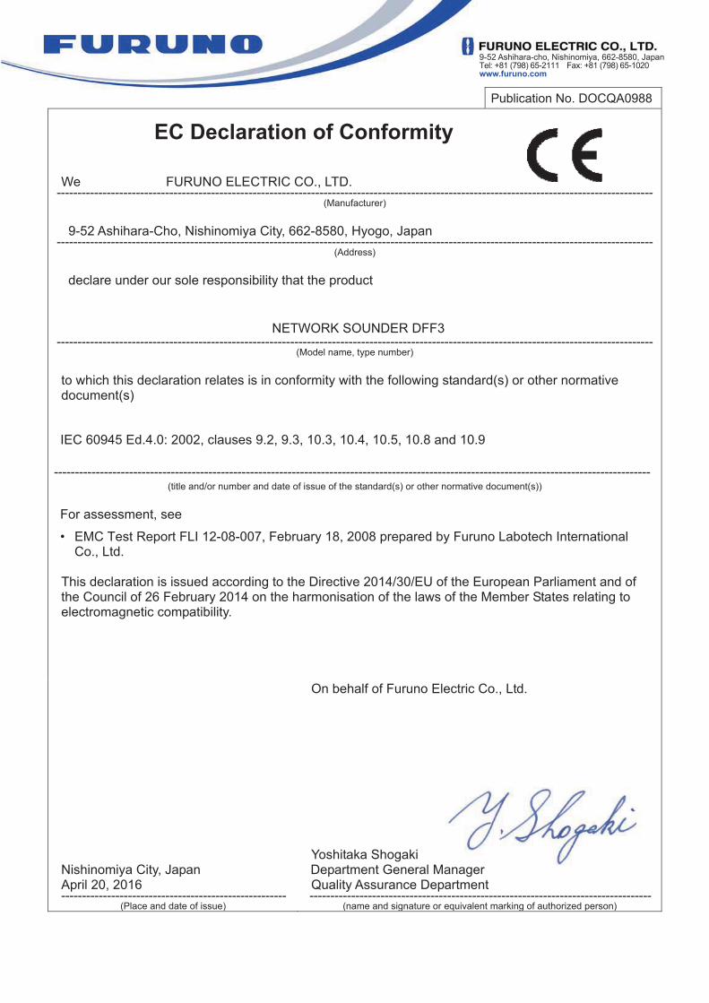
9-52 Ashihara-cho, Nishinomiya, 662-8580, JapanTel: +81 (798) 65-2111 Fax: +81 (798) 65-1020 www.furuno.com
Publication No. DOCQA0988
EC Declaration of Conformity We FURUNO ELECTRIC CO., LTD.
----------------------------------------------------------------------------------------------------------------------------------------------- (Manufacturer)
9-52 Ashihara-Cho, Nishinomiya City, 662-8580, Hyogo, Japan
----------------------------------------------------------------------------------------------------------------------------------------------- (Address)
declare under our sole responsibility that the product
NETWORK SOUNDER DFF3 -----------------------------------------------------------------------------------------------------------------------------------------------
(Model name, type number) to which this declaration relates is in conformity with the following standard(s) or other normative document(s) IEC 60945 Ed.4.0: 2002, clauses 9.2, 9.3, 10.3, 10.4, 10.5, 10.8 and 10.9
----------------------------------------------------------------------------------------------------------------------------------------------- (title and/or number and date of issue of the standard(s) or other normative document(s))
For assessment, see
• EMC Test Report FLI 12-08-007, February 18, 2008 prepared by Furuno Labotech International Co., Ltd.
This declaration is issued according to the Directive 2014/30/EU of the European Parliament and of the Council of 26 February 2014 on the harmonisation of the laws of the Member States relating to electromagnetic compatibility.
Nishinomiya City, Japan April 20, 2016 ------------------------------------------------------
(Place and date of issue)
On behalf of Furuno Electric Co., Ltd.
Yoshitaka Shogaki Department General Manager Quality Assurance Department ----------------------------------------------------------------------------------
(name and signature or equivalent marking of authorized person)


FURUNO Authorized Distributor/Dealer
Printed in Japan
(Elemental Chlorine Free)
The paper used in this manual is elemental chlorine free.
9-52, Ashihara-cho,Nishinomiya, 662-8580, JAPAN
All rights reserved.
Pub. No. OME-20370-G3
(TEHI) DFF3
A: MAR. 2008G3: NOV. 08, 2019
00016858216