Embed Size (px)
Citation preview
Operator's Manual
Partial Weight Bearing System for Gait
Training Therapy
By
Craig Hanna, Kyle Hamilton, and Nicholas Woolsey
University of Connecticut Biomedical Engineering Senior Design Team #11
Client Information
Christiana Gondreau, (401) 231-0647
2
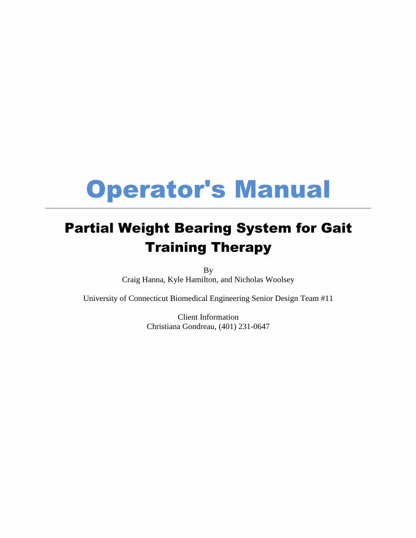
Part I: Safety Instructions
Proper safety is essential in using the partial weight bearing system for gait training
therapy system. Failure to do so could result in serious injury to the operator or the user. The
following section describes key safety features which are essential to observe when using the
partial weight bearing system.
I.i The Harness:
Proper securing of the harness is extremely important in order to ensure the safety of the
user while using the partial weight bearing system. The harness should first be placed on the
user. Before tightening the straps of the harness, fix the carabiners to the harness. The front two
carabiners are fixed to the black strap on the harness. Do not attach the carabiners directly to the
gray loop, as this may lead to the harness riding up, resulting in user discomfort. The back two
cables should be looped around the harness, passing through the green loops, securing the
carabiner to the cable once looped. DO NOT ATTACH THE CARABINERS DIRECTLY TO
THE GREEN LOOPS! These loops are not meant to be weight bearing, and are only present to
prevent the cables from moving around on the harness belt. Once all carabiners have been
attached, tightly secure the harness to the user.
I.ii Actuator Calibration:
Proper calibration of the actuator emergency stop button is crucial to the user's safety
when operating the partial weight bearing system. FAILURE TO PROPERLY CALIBRATE
THE ACTUATOR SYSTEM CAN LEAD TO SERIOUS USER INJURY! To properly calibrate
the actuator system, the user should be suspended in the partial weight bearing system above the
treadmill. Lower the user to the desired point of weight bearing, and stop the actuator. Mark the
point on the actuator where this point of desired weight bearing is. Remove the user from the
partial weight bearing system and mount the emergency stop button to the actuator at the marked
position. This button will prevent the user from being lowered too far into the treadmill if the
wireless remotes fail for any reason. DO NOT CALIBRATE THE ACTUATOR SYSTEM
WHILE THE TREADMILL IS RUNNING!
I.iii System Loading:
It is crucial to the user's and the operator's safety that the partial weight bearing system is
not over loaded. Although the load capacities of the actuator is 450lbs, and the pulley system is
capable of bearing up to 300 lbs, the child harness is only rated to 110lbs. DO NOT USE THE
CHILD HARNESS IF THE USER IS OVER 110LBS! A similar harness with higher weight
bearing capacities should be used if the user weighs more than 110lbs. For maximum safety, do
not load the system to more than 250lbs.
I.iv Electrical Components:
Always ensure that all cords are out of the way of the treadmill and the user before using
the partial weight bearing system. Always ensure the remote antenna is up while using the
wireless remotes to ensure maximum receiver responsiveness. Ensure that the receiver is always
tightly secured with the velcro straps in its proper housing. Always make sure the receiver
antenna is out of the way before operation.
3
II. Parts and Accessories:
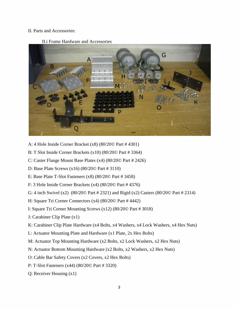
II.i Frame Hardware and Accessories
A: 4 Hole Inside Corner Bracket (x8) (80/20© Part # 4301)
B: T Slot Inside Corner Brackets (x10) (80/20© Part # 3364)
C: Caster Flange Mount Base Plates (x4) (80/20© Part # 2426)
D: Base Plate Screws (x16) (80/20© Part # 3110)
E: Base Plate T-Slot Fasteners (x8) (80/20© Part # 3458)
F: 3 Hole Inside Corner Brackets (x4) (80/20© Part # 4376)
G: 4 inch Swivel (x2) (80/20© Part # 2321) and Rigid (x2) Casters (80/20© Part # 2314)
H: Square Tri Corner Connectors (x4) (80/20© Part # 4442)
I: Square Tri Corner Mounting Screws (x12) (80/20© Part # 3018)
J: Carabiner Clip Plate (x1)
K: Carabiner Clip Plate Hardware (x4 Bolts, x4 Washers, x4 Lock Washers, x4 Hex Nuts)
L: Actuator Mounting Plate and Hardware (x1 Plate, 2x Hex Bolts)
M: Actuator Top Mounting Hardware (x2 Bolts, x2 Lock Washers, x2 Hex Nuts)
N: Actuator Bottom Mounting Hardware (x2 Bolts, x2 Washers, x2 Hex Nuts)
O: Cable Bar Safety Covers (x2 Covers, x2 Hex Bolts)
P: T-Slot Fasteners (x44) (80/20© Part # 3320)
Q: Receiver Housing (x1)
4
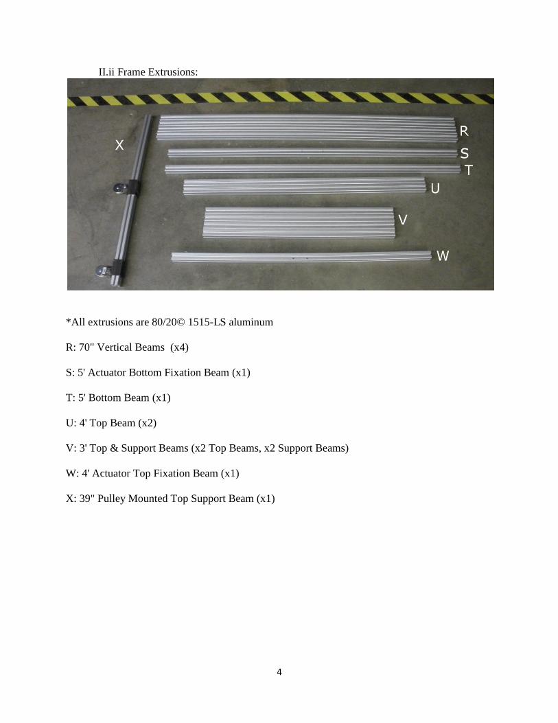
II.ii Frame Extrusions:
*All extrusions are 80/20© 1515-LS aluminum
R: 70" Vertical Beams (x4)
S: 5' Actuator Bottom Fixation Beam (x1)
T: 5' Bottom Beam (x1)
U: 4' Top Beam (x2)
V: 3' Top & Support Beams (x2 Top Beams, x2 Support Beams)
W: 4' Actuator Top Fixation Beam (x1)
X: 39" Pulley Mounted Top Support Beam (x1)
5
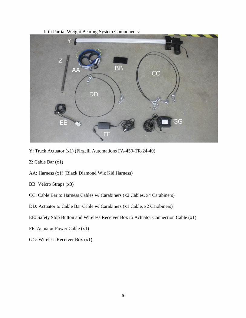
II.iii Partial Weight Bearing System Components:
Y: Track Actuator (x1) (Firgelli Automations FA-450-TR-24-40)
Z: Cable Bar (x1)
AA: Harness (x1) (Black Diamond Wiz Kid Harness)
BB: Velcro Straps (x3)
CC: Cable Bar to Harness Cables w/ Carabiners (x2 Cables, x4 Carabiners)
DD: Actuator to Cable Bar Cable w/ Carabiners (x1 Cable, x2 Carabiners)
EE: Safety Stop Button and Wireless Receiver Box to Actuator Connection Cable (x1)
FF: Actuator Power Cable (x1)
GG: Wireless Receiver Box (x1)
6
III. Device Features:
III.i The Frame
The device frame is constructed from 80/20© aluminum extrusions. This design allows
the device to be rapidly disassembled should it need to be moved. It is also lightweight and
strong, making it ideal for this project.
80/20© features a wide variety of connectors which can be used to assemble many
different structures. This project features the T-slot Connections which allow for maximum
structure stability vibration proofing. The connections work by partially screwing one of the T
slot screws into a fastener. These two components are both featured in the Parts and Accessories
section as Part P. The fastener is then inserted into the T slot of the extrusion and tightening the
screw down. The extrusions have T slots on all four sides, and these channels run the length of
each extrusion. This allows the fasteners to position any parts at any point on one of the four
faces of the beam, making this connection extremely versatile.
III.ii The Actuator
The track actuator was purchased from Firgelli Automations and has a 40" stroke length,
which allows for this system to work with children of varying heights. The long stroke means
that shorter children can still be lowered to the proper height within the frame in order to use the
system properly. Additionally, the actuator track speed with no load attached to it is only 0.39
inches per second, rendering the system able to supply finely adjustable weight bearing
capabilities. The actuator is able to support up to 450lbs of weight, which makes it very safe for
this application. Finally, it plugs directly into wall outlets, and the wireless remotes allow the
operator to assist the user while adjusting the variable weight support.
III.iii Harness and Braces
The partial weight bearing system utilizes a rock climbing harness and two braces to
provide support to the child while he uses the device. One brace provides back support,
enforcing proper posture while walking. The
other brace provides neck support for users who
have limited muscle function and require
additional head stability. The harness and braces
are easy to put on and easy to remove from the
system for washing in between uses.
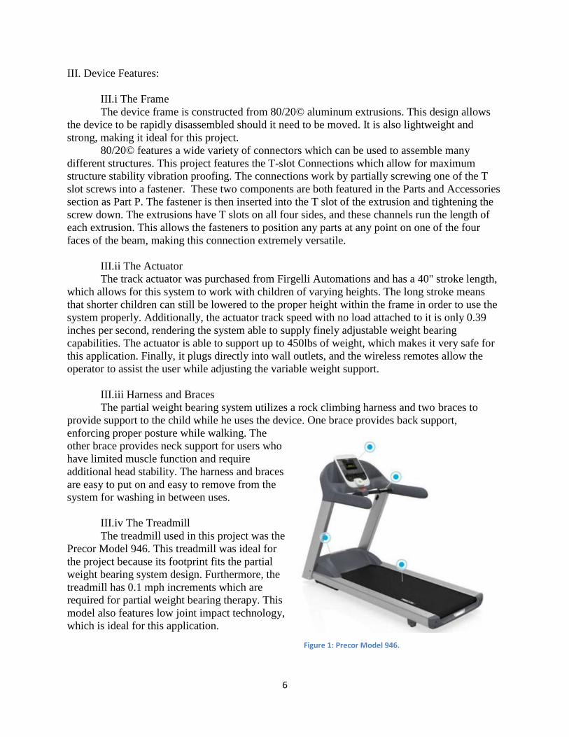
III.iv The Treadmill
The treadmill used in this project was the
Precor Model 946. This treadmill was ideal for
the project because its footprint fits the partial
weight bearing system design. Furthermore, the
treadmill has 0.1 mph increments which are
required for partial weight bearing therapy. This
model also features low joint impact technology,
which is ideal for this application.
Figure 1: Precor Model 946.

7
TABLE OF CONTENTS
1 Introduction: 8
1.1 General Device Overview and Assembly Instructions: 8
1.1a General Device Overview: 8
1.1b Device Assembly: 10
1.2 Device Use and Operation: 18
2 Maintenance: 20
2.1 Mechanical 20
2.1a 80/20© & Frame 20
2.1b Treadmill 20
2.1c Harness & Cables 21
2.2 Electrical
2.2a Wires and Cables 21
2.2b Wireless Remotes 21
2.3 Environmental 22
3 Technical Description: 22
3.1 80/20© Information 22
3.2 Track Actuator Information 23
3.3 Pulleys 24
3.4 Cable System 24
3.5 Harness and Braces 24
4 Trouble Shooting:
4.1 Frame 24
4.2 Weight Bearing System 25
8
1. Introduction
1.1 General Device Overview and Assembly Instructions:
1.1a Device Overview:
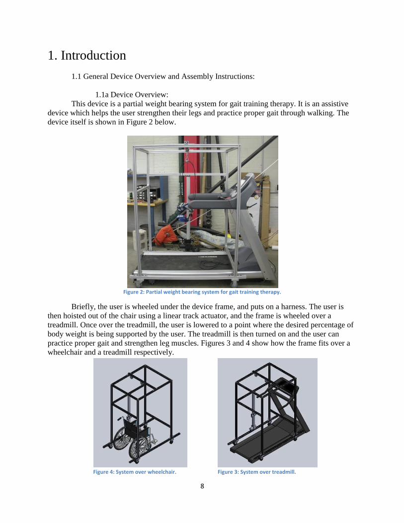
This device is a partial weight bearing system for gait training therapy. It is an assistive
device which helps the user strengthen their legs and practice proper gait through walking. The
device itself is shown in Figure 2 below.
Figure 2: Partial weight bearing system for gait training therapy.
Briefly, the user is wheeled under the device frame, and puts on a harness. The user is
then hoisted out of the chair using a linear track actuator, and the frame is wheeled over a
treadmill. Once over the treadmill, the user is lowered to a point where the desired percentage of
body weight is being supported by the user. The treadmill is then turned on and the user can
practice proper gait and strengthen leg muscles. Figures 3 and 4 show how the frame fits over a
wheelchair and a treadmill respectively.
Figure 4: System over wheelchair. Figure 3: System over treadmill.
9
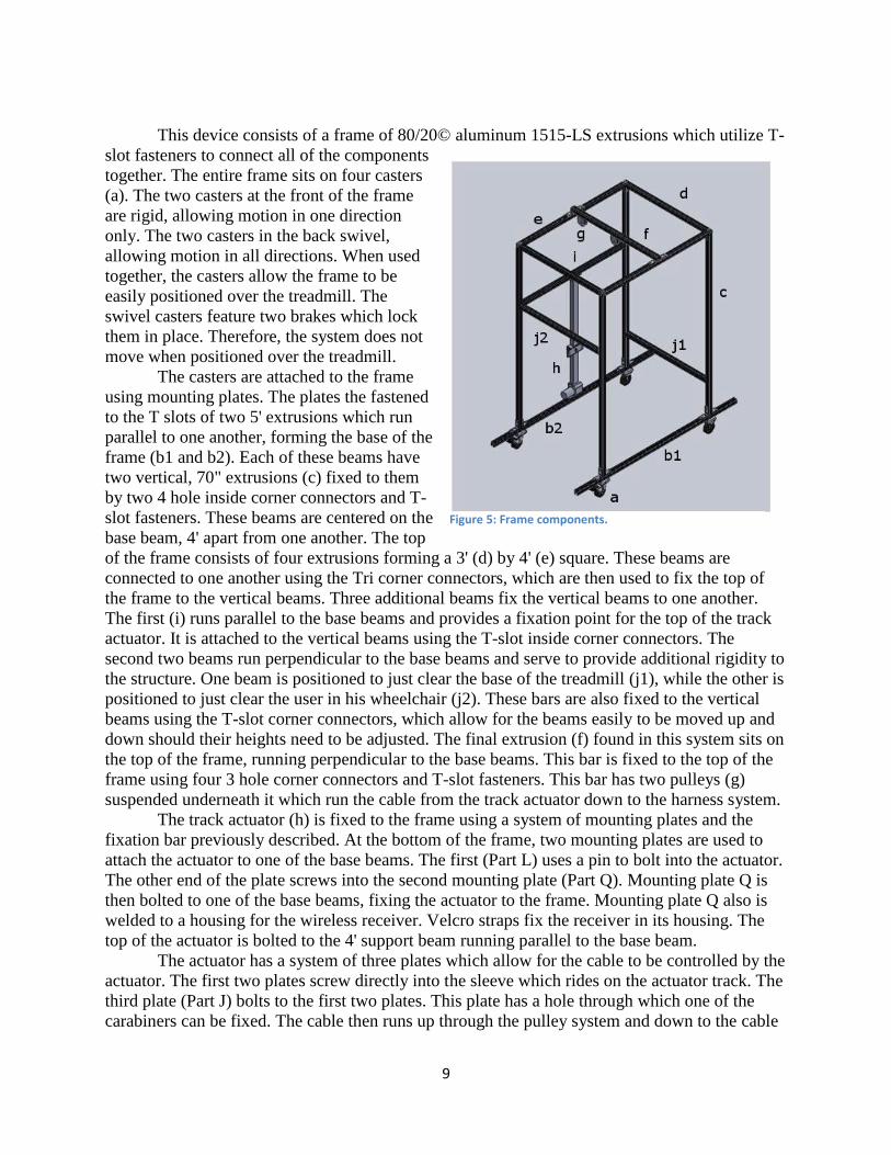
This device consists of a frame of 80/20© aluminum 1515-LS extrusions which utilize T-
slot fasteners to connect all of the components
together. The entire frame sits on four casters
(a). The two casters at the front of the frame
are rigid, allowing motion in one direction
only. The two casters in the back swivel,
allowing motion in all directions. When used
together, the casters allow the frame to be
easily positioned over the treadmill. The
swivel casters feature two brakes which lock
them in place. Therefore, the system does not
move when positioned over the treadmill.
The casters are attached to the frame
using mounting plates. The plates the fastened
to the T slots of two 5' extrusions which run
parallel to one another, forming the base of the
frame (b1 and b2). Each of these beams have
two vertical, 70" extrusions (c) fixed to them
by two 4 hole inside corner connectors and T-
slot fasteners. These beams are centered on the
base beam, 4' apart from one another. The top
of the frame consists of four extrusions forming a 3' (d) by 4' (e) square. These beams are
connected to one another using the Tri corner connectors, which are then used to fix the top of
the frame to the vertical beams. Three additional beams fix the vertical beams to one another.
The first (i) runs parallel to the base beams and provides a fixation point for the top of the track
actuator. It is attached to the vertical beams using the T-slot inside corner connectors. The
second two beams run perpendicular to the base beams and serve to provide additional rigidity to
the structure. One beam is positioned to just clear the base of the treadmill (j1), while the other is
positioned to just clear the user in his wheelchair (j2). These bars are also fixed to the vertical
beams using the T-slot corner connectors, which allow for the beams easily to be moved up and
down should their heights need to be adjusted. The final extrusion (f) found in this system sits on
the top of the frame, running perpendicular to the base beams. This bar is fixed to the top of the
frame using four 3 hole corner connectors and T-slot fasteners. This bar has two pulleys (g)
suspended underneath it which run the cable from the track actuator down to the harness system.
The track actuator (h) is fixed to the frame using a system of mounting plates and the
fixation bar previously described. At the bottom of the frame, two mounting plates are used to
attach the actuator to one of the base beams. The first (Part L) uses a pin to bolt into the actuator.
The other end of the plate screws into the second mounting plate (Part Q). Mounting plate Q is
then bolted to one of the base beams, fixing the actuator to the frame. Mounting plate Q also is
welded to a housing for the wireless receiver. Velcro straps fix the receiver in its housing. The
top of the actuator is bolted to the 4' support beam running parallel to the base beam.
The actuator has a system of three plates which allow for the cable to be controlled by the
actuator. The first two plates screw directly into the sleeve which rides on the actuator track. The
third plate (Part J) bolts to the first two plates. This plate has a hole through which one of the
carabiners can be fixed. The cable then runs up through the pulley system and down to the cable
Figure 5: Frame components.
10
bar. The cable coming from the actuator attaches to the cable bar by a carabiner. The two cables
which then run down to the harness itself sit in the cable bar in two rivets towards the end of the
cable bar. They are covered and kept in place by two plates which are screwed in over the rivets,
preventing the cables from falling out while the user is suspended in the system. The cables
attach to the harness with four carabiners. Two attach to the front in one of the loops and two
attach to the back, wrapped around the waistband of the harness clipping to the cable itself.
1.1b Device Assembly:
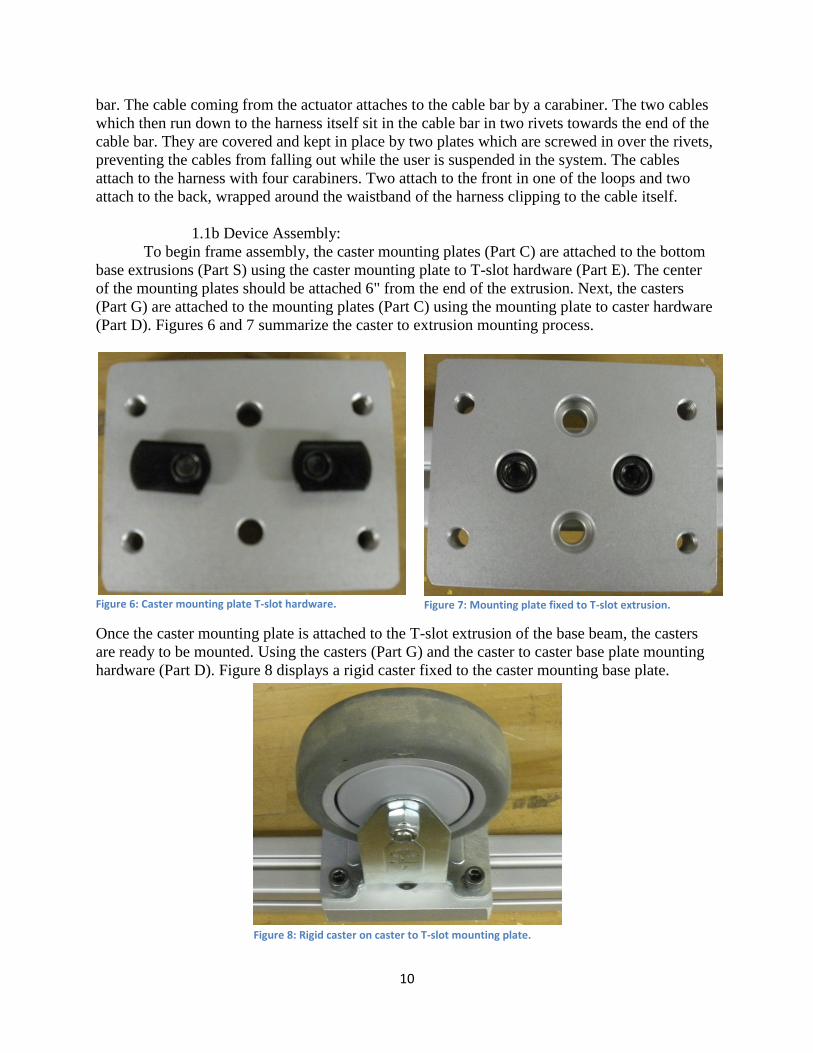
To begin frame assembly, the caster mounting plates (Part C) are attached to the bottom
base extrusions (Part S) using the caster mounting plate to T-slot hardware (Part E). The center
of the mounting plates should be attached 6" from the end of the extrusion. Next, the casters
(Part G) are attached to the mounting plates (Part C) using the mounting plate to caster hardware
(Part D). Figures 6 and 7 summarize the caster to extrusion mounting process.
Figure 6: Caster mounting plate T-slot hardware.
Once the caster mounting plate is attached to the T-slot extrusion of the base beam, the casters
are ready to be mounted. Using the casters (Part G) and the caster to caster base plate mounting
hardware (Part D). Figure 8 displays a rigid caster fixed to the caster mounting base plate.
Figure 7: Mounting plate fixed to T-slot extrusion.
Figure 8: Rigid caster on caster to T-slot mounting plate.
11
Repeat this process for the remaining three casters. When mounting casters to the base beam to
which the actuator bottom is fixed, ensure that the casters are mounted on the one of the faces
with holes in it.
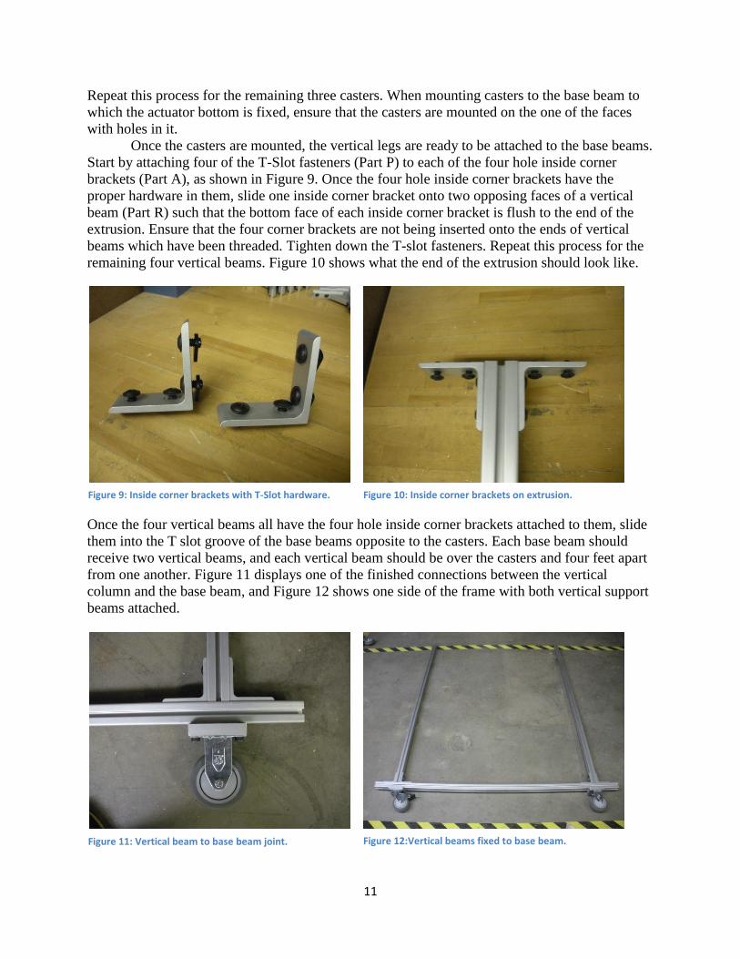
Once the casters are mounted, the vertical legs are ready to be attached to the base beams.
Start by attaching four of the T-Slot fasteners (Part P) to each of the four hole inside corner
brackets (Part A), as shown in Figure 9. Once the four hole inside corner brackets have the
proper hardware in them, slide one inside corner bracket onto two opposing faces of a vertical
beam (Part R) such that the bottom face of each inside corner bracket is flush to the end of the
extrusion. Ensure that the four corner brackets are not being inserted onto the ends of vertical
beams which have been threaded. Tighten down the T-slot fasteners. Repeat this process for the
remaining four vertical beams. Figure 10 shows what the end of the extrusion should look like.
Once the four vertical beams all have the four hole inside corner brackets attached to them, slide
them into the T slot groove of the base beams opposite to the casters. Each base beam should
receive two vertical beams, and each vertical beam should be over the casters and four feet apart
from one another. Figure 11 displays one of the finished connections between the vertical
column and the base beam, and Figure 12 shows one side of the frame with both vertical support
beams attached.
Figure 9: Inside corner brackets with T-Slot hardware. Figure 10: Inside corner brackets on extrusion.
Figure 11: Vertical beam to base beam joint. Figure 12:Vertical beams fixed to base beam.
12
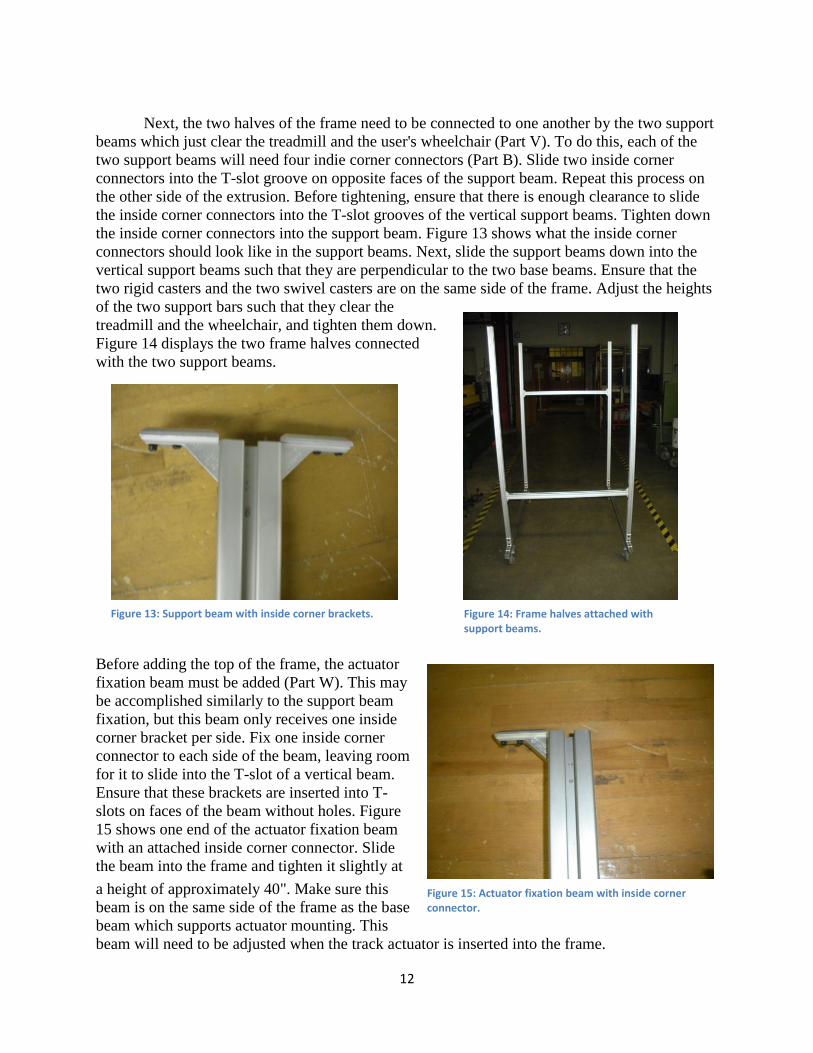
Next, the two halves of the frame need to be connected to one another by the two support
beams which just clear the treadmill and the user's wheelchair (Part V). To do this, each of the
two support beams will need four indie corner connectors (Part B). Slide two inside corner
connectors into the T-slot groove on opposite faces of the support beam. Repeat this process on
the other side of the extrusion. Before tightening, ensure that there is enough clearance to slide
the inside corner connectors into the T-slot grooves of the vertical support beams. Tighten down
the inside corner connectors into the support beam. Figure 13 shows what the inside corner
connectors should look like in the support beams. Next, slide the support beams down into the
vertical support beams such that they are perpendicular to the two base beams. Ensure that the
two rigid casters and the two swivel casters are on the same side of the frame. Adjust the heights
of the two support bars such that they clear the
treadmill and the wheelchair, and tighten them down.
Figure 14 displays the two frame halves connected
with the two support beams.
Before adding the top of the frame, the actuator
fixation beam must be added (Part W). This may
be accomplished similarly to the support beam
fixation, but this beam only receives one inside
corner bracket per side. Fix one inside corner
connector to each side of the beam, leaving room
for it to slide into the T-slot of a vertical beam.
Ensure that these brackets are inserted into T-
slots on faces of the beam without holes. Figure
15 shows one end of the actuator fixation beam
with an attached inside corner connector. Slide
the beam into the frame and tighten it slightly at
a height of approximately 40". Make sure this
beam is on the same side of the frame as the base
beam which supports actuator mounting. This
beam will need to be adjusted when the track actuator is inserted into the frame.
Figure 13: Support beam with inside corner brackets. Figure 14: Frame halves attached with support beams.
Figure 15: Actuator fixation beam with inside corner connector.
13
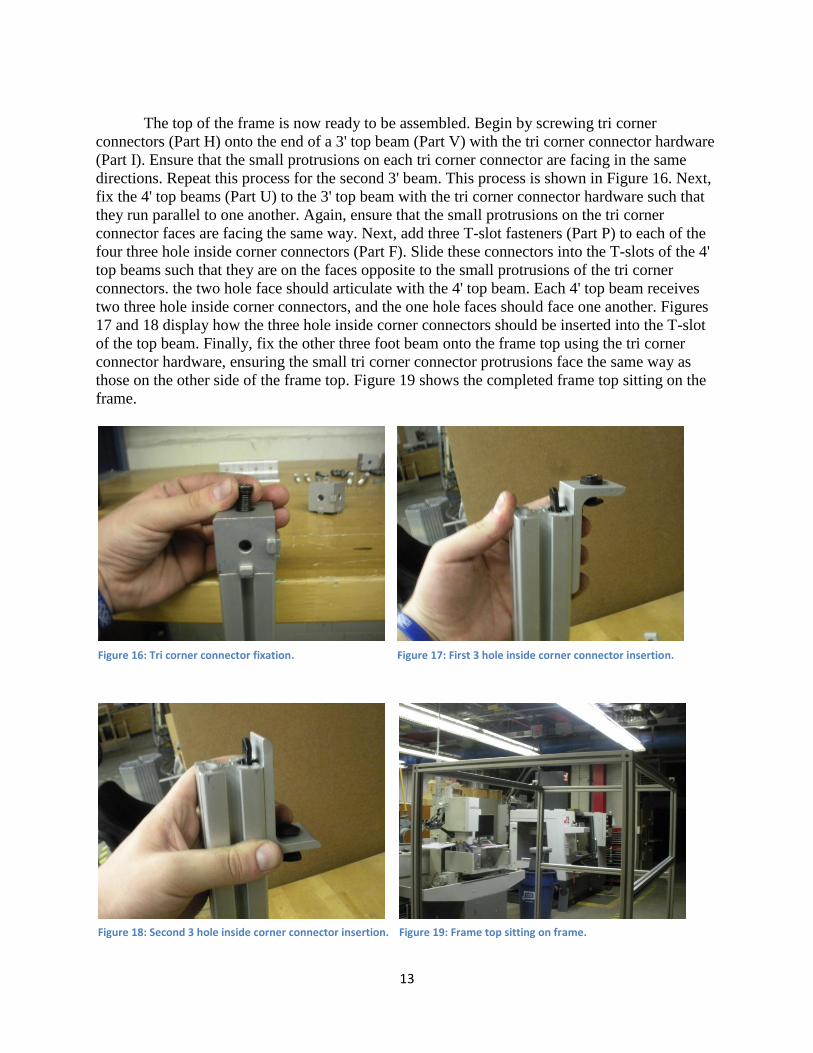
The top of the frame is now ready to be assembled. Begin by screwing tri corner
connectors (Part H) onto the end of a 3' top beam (Part V) with the tri corner connector hardware
(Part I). Ensure that the small protrusions on each tri corner connector are facing in the same
directions. Repeat this process for the second 3' beam. This process is shown in Figure 16. Next,
fix the 4' top beams (Part U) to the 3' top beam with the tri corner connector hardware such that
they run parallel to one another. Again, ensure that the small protrusions on the tri corner
connector faces are facing the same way. Next, add three T-slot fasteners (Part P) to each of the
four three hole inside corner connectors (Part F). Slide these connectors into the T-slots of the 4'
top beams such that they are on the faces opposite to the small protrusions of the tri corner
connectors. the two hole face should articulate with the 4' top beam. Each 4' top beam receives
two three hole inside corner connectors, and the one hole faces should face one another. Figures
17 and 18 display how the three hole inside corner connectors should be inserted into the T-slot
of the top beam. Finally, fix the other three foot beam onto the frame top using the tri corner
connector hardware, ensuring the small tri corner connector protrusions face the same way as
those on the other side of the frame top. Figure 19 shows the completed frame top sitting on the
frame.
Figure 16: Tri corner connector fixation. Figure 17: First 3 hole inside corner connector insertion.
Figure 18: Second 3 hole inside corner connector insertion. Figure 19: Frame top sitting on frame.
14
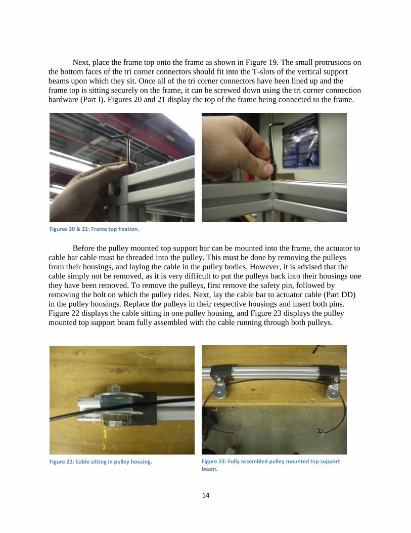
Next, place the frame top onto the frame as shown in Figure 19. The small protrusions on
the bottom faces of the tri corner connectors should fit into the T-slots of the vertical support
beams upon which they sit. Once all of the tri corner connectors have been lined up and the
frame top is sitting securely on the frame, it can be screwed down using the tri corner connection
hardware (Part I). Figures 20 and 21 display the top of the frame being connected to the frame.
Before the pulley mounted top support bar can be mounted into the frame, the actuator to
cable bar cable must be threaded into the pulley. This must be done by removing the pulleys
from their housings, and laying the cable in the pulley bodies. However, it is advised that the
cable simply not be removed, as it is very difficult to put the pulleys back into their housings one
they have been removed. To remove the pulleys, first remove the safety pin, followed by
removing the bolt on which the pulley rides. Next, lay the cable bar to actuator cable (Part DD)
in the pulley housings. Replace the pulleys in their respective housings and insert both pins.
Figure 22 displays the cable sitting in one pulley housing, and Figure 23 displays the pulley
mounted top support beam fully assembled with the cable running through both pulleys.
Figures 20 & 21: Frame top fixation.
Figure 22: Cable sitting in pulley housing. Figure 23: Fully assembled pulley mounted top support beam.
15
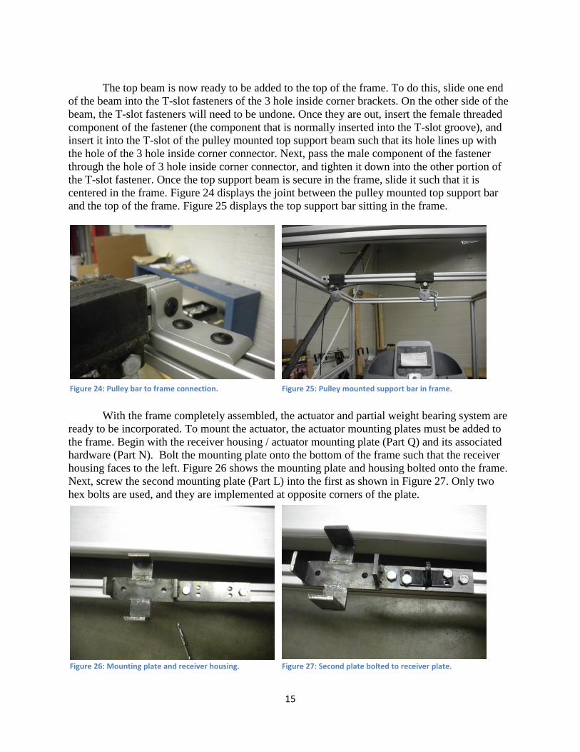
The top beam is now ready to be added to the top of the frame. To do this, slide one end
of the beam into the T-slot fasteners of the 3 hole inside corner brackets. On the other side of the
beam, the T-slot fasteners will need to be undone. Once they are out, insert the female threaded
component of the fastener (the component that is normally inserted into the T-slot groove), and
insert it into the T-slot of the pulley mounted top support beam such that its hole lines up with
the hole of the 3 hole inside corner connector. Next, pass the male component of the fastener
through the hole of 3 hole inside corner connector, and tighten it down into the other portion of
the T-slot fastener. Once the top support beam is secure in the frame, slide it such that it is
centered in the frame. Figure 24 displays the joint between the pulley mounted top support bar
and the top of the frame. Figure 25 displays the top support bar sitting in the frame.
With the frame completely assembled, the actuator and partial weight bearing system are
ready to be incorporated. To mount the actuator, the actuator mounting plates must be added to
the frame. Begin with the receiver housing / actuator mounting plate (Part Q) and its associated
hardware (Part N). Bolt the mounting plate onto the bottom of the frame such that the receiver
housing faces to the left. Figure 26 shows the mounting plate and housing bolted onto the frame.
Next, screw the second mounting plate (Part L) into the first as shown in Figure 27. Only two
hex bolts are used, and they are implemented at opposite corners of the plate.
Figure 24: Pulley bar to frame connection. Figure 25: Pulley mounted support bar in frame.
Figure 26: Mounting plate and receiver housing. Figure 27: Second plate bolted to receiver plate.
16
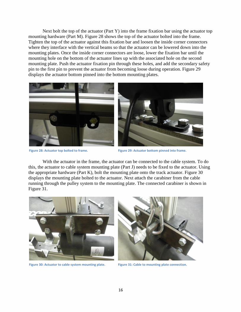
Next bolt the top of the actuator (Part Y) into the frame fixation bar using the actuator top
mounting hardware (Part M). Figure 28 shows the top of the actuator bolted into the frame.
Tighten the top of the actuator against this fixation bar and loosen the inside corner connectors
where they interface with the vertical beams so that the actuator can be lowered down into the
mounting plates. Once the inside corner connectors are loose, lower the fixation bar until the
mounting hole on the bottom of the actuator lines up with the associated hole on the second
mounting plate. Push the actuator fixation pin through these holes, and add the secondary safety
pin to the first pin to prevent the actuator from becoming loose during operation. Figure 29
displays the actuator bottom pinned into the bottom mounting plates.
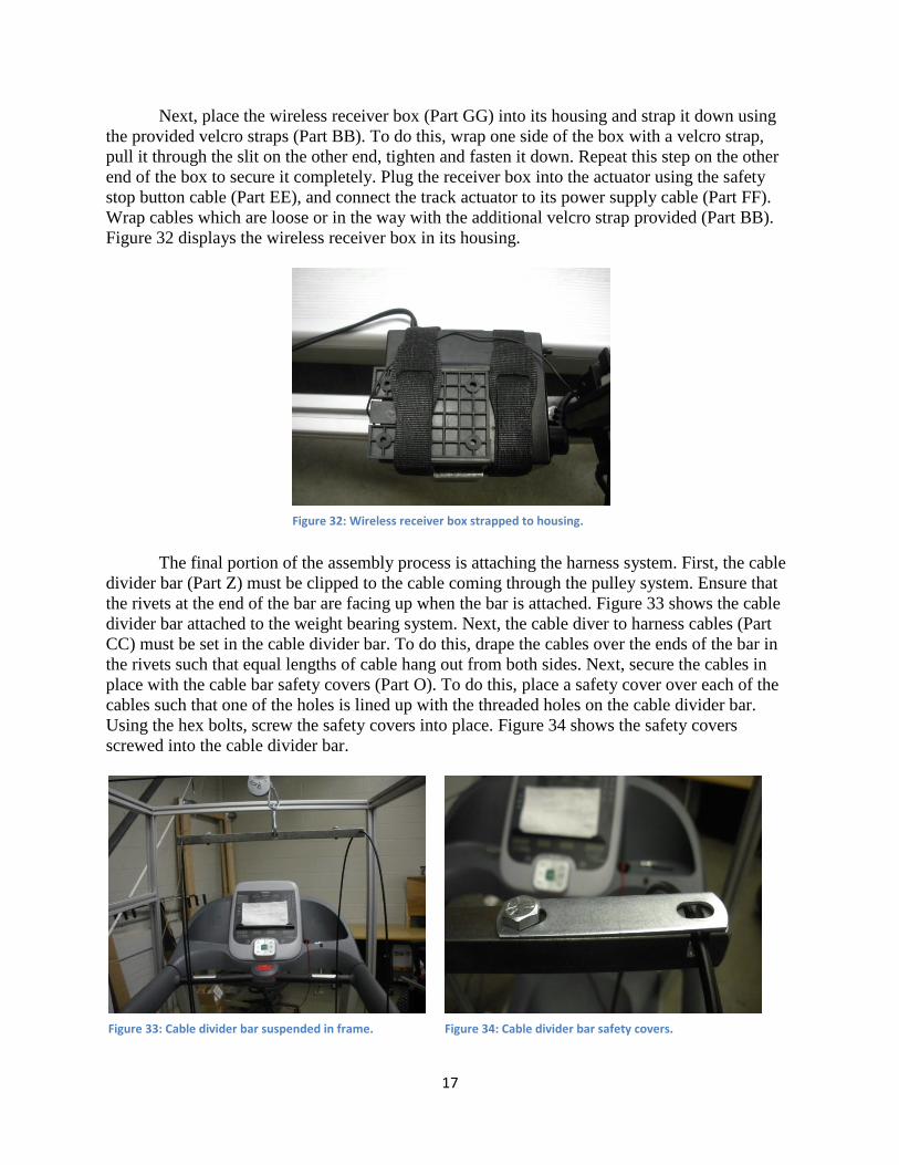
With the actuator in the frame, the actuator can be connected to the cable system. To do
this, the actuator to cable system mounting plate (Part J) needs to be fixed to the actuator. Using
the appropriate hardware (Part K), bolt the mounting plate onto the track actuator. Figure 30
displays the mounting plate bolted to the actuator. Next attach the carabiner from the cable
running through the pulley system to the mounting plate. The connected carabiner is shown in
Figure 31.
Figure 28: Actuator top bolted to frame. Figure 29: Actuator bottom pinned into frame.
Figure 30: Actuator to cable system mounting plate. Figure 31: Cable to mounting plate connection.
17
Next, place the wireless receiver box (Part GG) into its housing and strap it down using
the provided velcro straps (Part BB). To do this, wrap one side of the box with a velcro strap,
pull it through the slit on the other end, tighten and fasten it down. Repeat this step on the other
end of the box to secure it completely. Plug the receiver box into the actuator using the safety
stop button cable (Part EE), and connect the track actuator to its power supply cable (Part FF).
Wrap cables which are loose or in the way with the additional velcro strap provided (Part BB).
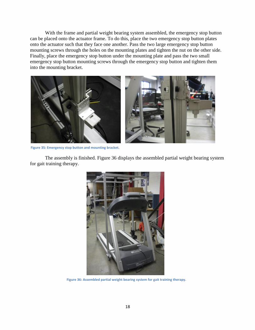
Figure 32 displays the wireless receiver box in its housing.
The final portion of the assembly process is attaching the harness system. First, the cable
divider bar (Part Z) must be clipped to the cable coming through the pulley system. Ensure that
the rivets at the end of the bar are facing up when the bar is attached. Figure 33 shows the cable
divider bar attached to the weight bearing system. Next, the cable diver to harness cables (Part
CC) must be set in the cable divider bar. To do this, drape the cables over the ends of the bar in
the rivets such that equal lengths of cable hang out from both sides. Next, secure the cables in
place with the cable bar safety covers (Part O). To do this, place a safety cover over each of the
cables such that one of the holes is lined up with the threaded holes on the cable divider bar.
Using the hex bolts, screw the safety covers into place. Figure 34 shows the safety covers
screwed into the cable divider bar.
Figure 32: Wireless receiver box strapped to housing.
Figure 33: Cable divider bar suspended in frame. Figure 34: Cable divider bar safety covers.
18
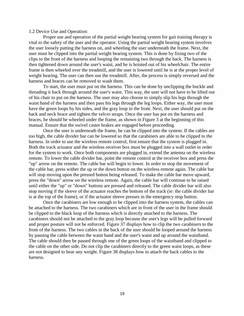
With the frame and partial weight bearing system assembled, the emergency stop button
can be placed onto the actuator frame. To do this, place the two emergency stop button plates
onto the actuator such that they face one another. Pass the two large emergency stop button
mounting screws through the holes on the mounting plates and tighten the nut on the other side.
Finally, place the emergency stop button under the mounting plate and pass the two small
emergency stop button mounting screws through the emergency stop button and tighten them
into the mounting bracket.
The assembly is finished. Figure 36 displays the assembled partial weight bearing system
for gait training therapy.
Figure 36: Assembled partial weight bearing system for gait training therapy.
Figure 35: Emergency stop button and mounting bracket.
19
1.2 Device Use and Operation:
Proper use and operation of the partial weight bearing system for gait training therapy is
vital to the safety of the user and the operator. Using the partial weight bearing system involves
the user loosely putting the harness on, and wheeling the user underneath the frame. Next, the
user must be clipped into the partial weight bearing system. This is done by fixing two of the
clips to the front of the harness and looping the remaining two through the back. The harness is
then tightened down around the user's waist, and he is hoisted out of his wheelchair. The entire
frame is then wheeled over the treadmill, and the user is lowered until he is at the proper level of
weight bearing. The user can then use the treadmill. After, the process is simply reversed and the
harness and braces can be removed to wash them.
To start, the user must put on the harness. This can be done by unclipping the buckle and
threading it back through around the user's waist. This way, the user will not have to be lifted out
of his chair to put on the harness. The user may also choose to simply slip his legs through the
waist band of the harness and then pass his legs through the leg loops. Either way, the user must
have the green loops by his sides, and the gray loop in the front. Next, the user should put on the
back and neck brace and tighten the velcro straps. Once the user has put on the harness and
braces, he should be wheeled under the frame, as shown in Figure 3 at the beginning of this
manual. Ensure that the swivel caster brakes are engaged before proceeding.
Once the user is underneath the frame, he can be clipped into the system. If the cables are
too high, the cable divider bar can be lowered so that the carabiners are able to be clipped to the
harness. In order to use the wireless remote control, first ensure that the system is plugged in.
Both the track actuator and the wireless receiver box must be plugged into a wall outlet in order
for the system to work. Once both components are plugged in, extend the antenna on the wireless
remote. To lower the cable divider bar, point the remote control at the receiver box and press the
"up" arrow on the remote. The cable bar will begin to lower. In order to stop the movement of
the cable bar, press wither the up or the down button on the wireless remote again. The cable bar
will stop moving upon the pressed button being released. To make the cable bar move upward,
press the "down" arrow on the wireless remote. Again, the cable bar will continue to be raised
until either the "up" or "down" buttons are pressed and released. The cable divider bar will also
stop moving if the sleeve of the actuator reaches the bottom of the track (ie: the cable divider bar
is at the top of the frame), or if the actuator sleeve presses in the emergency stop button.
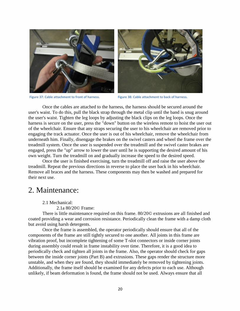
Once the carabiners are low enough to be clipped into the harness system, the cables can
be attached to the harness. The two carabiners which are in front of the user in the frame should
be clipped to the black loop of the harness which is directly attached to the harness. The
carabiners should not be attached to the gray loop because the user's legs will be pulled forward
and proper posture will not be enforced. Figure 37 displays how to clip the two carabiners to the
front of the harness. The two cables in the back of the user should be looped around the harness
by passing the cable between the waist band and the user's waist and up around the waistband.
The cable should then be passed through one of the green loops of the waistband and clipped to
the cable on the other side. Do not clip the carabiners directly to the green waist loops, as these
are not designed to bear any weight. Figure 38 displays how to attach the back cables to the
harness.
20
Once the cables are attached to the harness, the harness should be secured around the
user's waist. To do this, pull the black strap through the metal clip until the band is snug around
the user's waist. Tighten the leg loops by adjusting the black clips on the leg loops. Once the
harness is secure on the user, press the "down" button on the wireless remote to hoist the user out
of the wheelchair. Ensure that any straps securing the user to his wheelchair are removed prior to
engaging the track actuator. Once the user is out of his wheelchair, remove the wheelchair from
underneath him. Finally, disengage the brakes on the swivel casters and wheel the frame over the
treadmill system. Once the user is suspended over the treadmill and the swivel caster brakes are
engaged, press the "up" arrow to lower the user until he is supporting the desired amount of his
own weight. Turn the treadmill on and gradually increase the speed to the desired speed.
Once the user is finished exercising, turn the treadmill off and raise the user above the
treadmill. Repeat the previous directions in reverse to place the user back in his wheelchair.
Remove all braces and the harness. These components may then be washed and prepared for
their next use.
2. Maintenance:
2.1 Mechanical:
2.1a 80/20© Frame:
There is little maintenance required on this frame. 80/20© extrusions are all finished and
coated providing a wear and corrosion resistance. Periodically clean the frame with a damp cloth
but avoid using harsh detergents.
Once the frame is assembled, the operator periodically should ensure that all of the
components of the frame are still tightly secured to one another. All joints in this frame are
vibration proof, but incomplete tightening of some T-slot connectors or inside corner joints
during assembly could result in frame instability over time. Therefore, it is a good idea to
periodically check and tighten all joints in the frame. Also, the operator should check for gaps
between the inside corner joints (Part B) and extrusions. These gaps render the structure more
unstable, and when they are found, they should immediately be removed by tightening joints.
Additionally, the frame itself should be examined for any defects prior to each use. Although
unlikely, if beam deformation is found, the frame should not be used. Always ensure that all
Figure 37: Cable attachment to front of harness. Figure 38: Cable attachment to back of harness.
21
safety pins, such as those found in the pulleys and the pin at the bottom of the actuator, are
engaged prior to use of the partial weight bearing system.
The holes at the tops of the vertical beams and the holes in the top beams which were
threaded may occasionally some cleaning. If particulate gets into the tapped holes, screwing the
tri corner connectors into the extrusions may become difficult. Oiling these joints prior to
screwing the tri corner connectors onto the end of may facilitate this process. Additionally, the
casters in the frame may require periodic oiling to maximize performance.
2.1b Treadmill:
The treadmill may occasionally require some mechanical maintenance. This may include
realigning the belt of the treadmill or oiling the belt so that it runs more smoothly. To check the
belt alignment of the Precor 946 treadmill, turn the treadmill on and press quick start while
standing beside it. Walk to the back of the treadmill and observe the running belt. If the belt is
not running centered on the treadmill, it may need to be adjusted. Turn the treadmill off and
locater the belt adjustment bolt at the right, rear portion of the treadmill. Using a 1/4" hex key,
turn the adjustment bolt counter clockwise to move the belt left, and clockwise to move the belt
right. Additional information regarding the treadmill system and its care can be found on the
manufacturer's website.
2.1c Harness and Cable Systems:
Periodic washing of the harness and the brace system is advised in order to keep them
clean and functional. Do not wash the harness with any harsh detergents, as this may
compromise the harness. Do not keep the harness exposed to prolonged sunlight. The harness
should be inspected before every use. Do not use the harness if any damage or abrasion is found
on the harness straps or clips. The cable system should also be inspected prior to every use.
Cables which are frayed or damaged in any way should not be used.
2.2 Electrical:
2.2a Wires and Cables:
Electrical components and cables should always be kept away from the moving parts of
the treadmill and the partial weight bearing system itself. Use the velcro straps to secure any
loose cables to one another and always keep these cables as short as possible in order to prevent
accidents which may be cause from loose cables. Additionally, the antenna on the receiver box
should always be secured to the box with the velcro straps in order to prevent damage to the
antenna.
2.2b Wireless Remotes:
The wireless remotes should always be stored with the antennas retracted into their
housings. This will prevent accidental damage to the antennas, which are vital to the function of
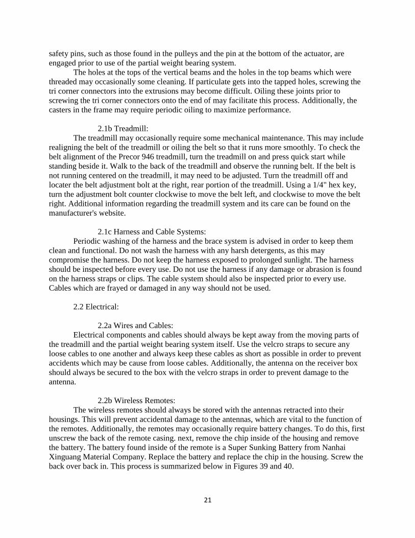
the remotes. Additionally, the remotes may occasionally require battery changes. To do this, first
unscrew the back of the remote casing. next, remove the chip inside of the housing and remove
the battery. The battery found inside of the remote is a Super Sunking Battery from Nanhai
Xinguang Material Company. Replace the battery and replace the chip in the housing. Screw the
back over back in. This process is summarized below in Figures 39 and 40.
22
The emergency safety stop button may occasionally need to be readjusted in order to compensate
for growth of the user or to allow for a greater factor of weight bearing.
2.3 Environmental:
The treadmill and frame are designed for inside use only! The frame itself should be kept
in clean and dry environment. Moisture could lead to the corrosion of some components, and
possible failure of some electrical components. Components of the treadmill or the partial weight
bearing system should never be stored or transported in areas where they may be exposed to
extreme temperatures or harmful chemicals.
The treadmill and the partial weight bearing system should always be used in an
environment which is clean and uncluttered. The lack of clear space around the support system
could lead to accidental injury of either the user or the operator while the support system is in
use.
3. Technical Description:
3.1 80/20© Frame:
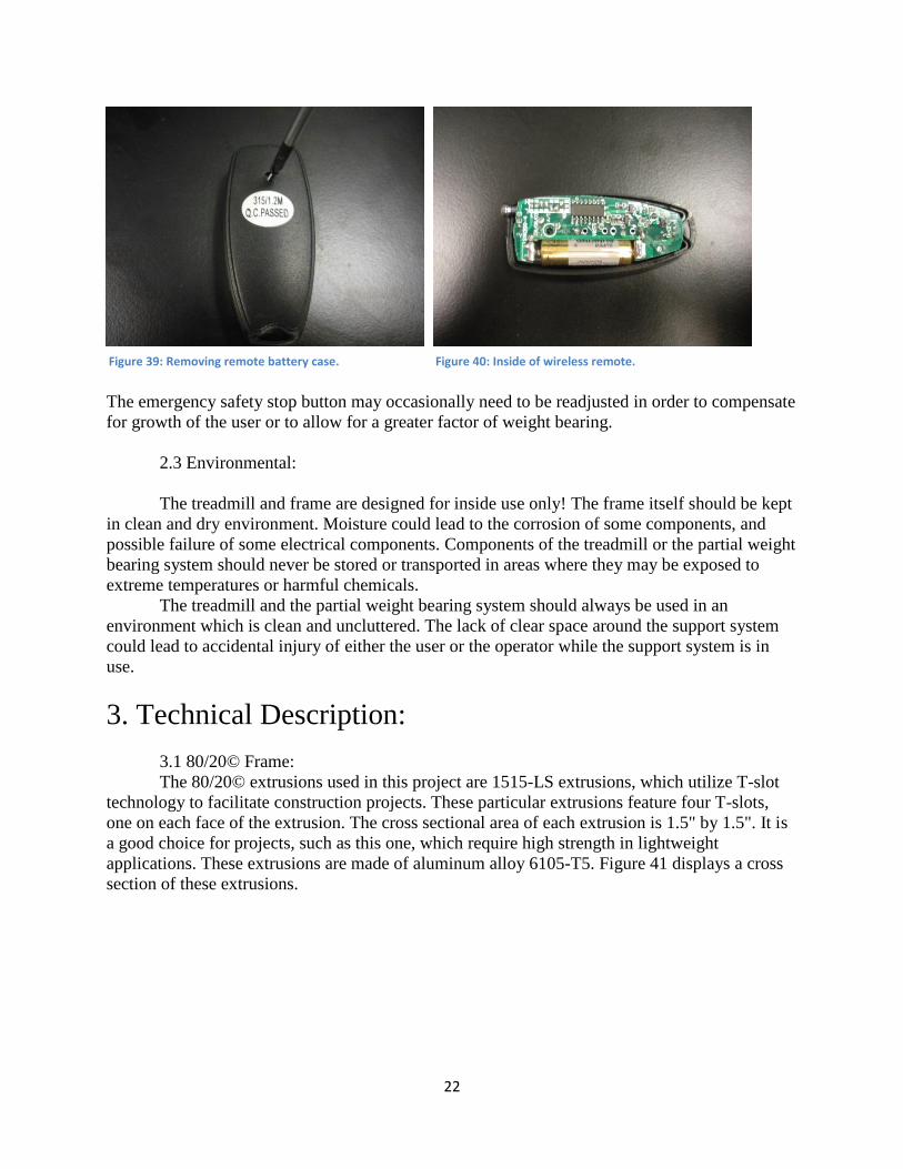
The 80/20© extrusions used in this project are 1515-LS extrusions, which utilize T-slot
technology to facilitate construction projects. These particular extrusions feature four T-slots,
one on each face of the extrusion. The cross sectional area of each extrusion is 1.5" by 1.5". It is
a good choice for projects, such as this one, which require high strength in lightweight
applications. These extrusions are made of aluminum alloy 6105-T5. Figure 41 displays a cross
section of these extrusions.
Figure 39: Removing remote battery case. Figure 40: Inside of wireless remote.
23
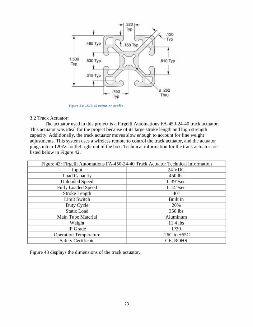
3.2 Track Actuator:
The actuator used in this project is a Firgelli Automations FA-450-24-40 track actuator.
This actuator was ideal for the project because of its large stroke length and high strength
capacity. Additionally, the track actuator moves slow enough to account for fine weight
adjustments. This system uses a wireless remote to control the track actuator, and the actuator
plugs into a 120AC outlet right out of the box. Technical information for the track actuator are
listed below in Figure 42.
Figure 42: Firgelli Automations FA-450-24-40 Track Actuator Technical Information
Input 24 VDC
Load Capacity 450 lbs
Unloaded Speed 0.39"/sec
Fully Loaded Speed 0.14"/sec
Stroke Length 40"
Limit Switch Built in
Duty Cycle 20%
Static Load 350 lbs
Main Tube Material Aluminum
Weight 11.4 lbs
IP Grade IP20
Operation Temperature -26C to +65C
Safety Certificate CE, ROHS
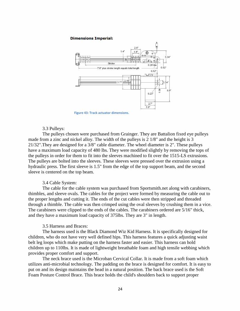
Figure 43 displays the dimensions of the track actuator.
Figure 41: 1515-LS extrusion profile.
24
3.3 Pulleys:
The pulleys chosen were purchased from Grainger. They are Battalion fixed eye pulleys
made from a zinc and nickel alloy. The width of the pulleys is 2 1/8" and the height is 3
21/32".They are designed for a 3/8" cable diameter. The wheel diameter is 2". These pulleys
have a maximum load capacity of 480 lbs. They were modified slightly by removing the tops of
the pulleys in order for them to fit into the sleeves machined to fit over the 1515-LS extrusions.
The pulleys are bolted into the sleeves. These sleeves were pressed over the extrusion using a
hydraulic press. The first sleeve is 1.5" from the edge of the top support beam, and the second
sleeve is centered on the top beam.
3.4 Cable System:
The cable for the cable system was purchased from Sportsmith.net along with carabiners,
thimbles, and sleeve ovals. The cables for the project were formed by measuring the cable out to
the proper lengths and cutting it. The ends of the cut cables were then stripped and threaded
through a thimble. The cable was then crimped using the oval sleeves by crushing them in a vice.
The carabiners were clipped to the ends of the cables. The carabiners ordered are 5/16" thick,
and they have a maximum load capacity of 375lbs. They are 3" in length.
3.5 Harness and Braces:
The harness used is the Black Diamond Wiz Kid Harness. It is specifically designed for
children, who do not have very well defined hips. This harness features a quick adjusting waist
belt leg loops which make putting on the harness faster and easier. This harness can hold
children up to 110lbs. It is made of lightweight breathable foam and high tensile webbing which
provides proper comfort and support.
The neck brace used is the Microban Cervical Collar. It is made from a soft foam which
utilizes anti-microbial technology. The padding on the brace is designed for comfort. It is easy to
put on and its design maintains the head in a natural position. The back brace used is the Soft
Foam Posture Control Brace. This brace holds the child's shoulders back to support proper
Figure 43: Track actuator dimensions.
25
posture. The brace can be used during activity. The material used is soft, breathable, flexible, and
cool.
4. Trouble Shooting:
4.1 The Frame:
Problem:
Lack of rigidity in the frame.
Solution:
Check all joints in the frame for loose connections. Particularly, there may be loose
connections in between the support beams and the vertical support beams. This may result from
loose connections in the inside corner connectors between these two beams. To fix this, loosen
the inside corner connectors and press the beams together. Tighten the inside corner connectors
while the beams are tight together and test their rigidity after. Make sure the caster brakes are
engaged while doing this.
Problem:
T-slot fasteners will not tighten down.
Solution:
If the T-slot fasteners will not tighten in the frame, then the back has likely fallen out
inside of the T-slot groove of the extrusion. Attempt to locate the back of the fastener in the
groove and align it with the fastener screw. Tighten the fastener. Additionally, the extrusion may
be removed and the fastener will slide out of the end of the extrusion.
Problem:
Frame will not move.
Solution:
If the frame will not move, the brakes are likely engaged. To remove the brakes on the
casters, push up on the black brake until it snaps up and is parallel with the floor. If the brakes
are already disengaged, check the casters for anything that might be caught in their housings.
Periodic oiling of the casters should help extend their life and facilitate moving the frame.
4.2 The Actuator:
Problem:
Remote light will not turn on when pressing buttons.
Solution:
If the actuator stops responding, the most likely cause is a dead battery. Replace the
battery, and test the wireless remote again. If the light still does not turn on, then the remote itself
may be dead. Figelli Automations sells additional wireless remotes for these actuators on their
website.

26
Problem:
Remote light is turning on, but actuator is not moving.
Solution:
If the remote is lighting up but the actuator is not moving, it is likely that the wireless
receiver box simply cannot read the signal. The remotes work best when the antenna is raised
and they are pointed directly at the receiver box antenna. Additionally, ensure that the emergency
safety stop button is not pressed in, as this may be preventing the actuator from moving in one
direction.
If the receiver box is still not turning on, check to see if the box is hot. If the box is very
warm to the touch, immediately unplug it and let it cool down. Remove the plug from the box
itself and examine the prongs. The prongs may become bent out of shape if the cable is not
inserted properly. Ensure that all prongs are facing outward and the cable is plugging in properly.
If these solutions do not work, the receiver box may be dead. Firgelli automations sells
replacement wireless receiver boxes on their website.


![1010 woolsey[1]](https://img.pdfslide.net/doc/110x75/55a27ed71a28ab15408b465e/1010-woolsey1.jpg)