Embed Size (px)
DESCRIPTION
Building Network Topologies /Steps for Building a Network Topology /Examples of Various Topologies Used for /Different Studies /Lab 3 – Switched LANs
Citation preview
OPNET IT Guru Academic Edition
Chapter 4 LAB 3 – Switched LANs
N. Abedpoor
Imam Reza International University of Mashhad
N. Abedpoor – International Imam Reza University of Mashhad Dec. 2013
● Building Network Topologies
• Steps for Building a Network Topology
• Examples of Various Topologies Used for Different
Studies
● Lab 3 – Switched LANs
Chapter 4 Lab3 – Switched LANs
N. Abedpoor – International Imam Reza University of Mashhad Dec. 2013 2
● The software supports many different techniques for building
network topologies. Topologies can be created manually or
imported from tools that perform auto-discovery. The model
library that comes with the software provides models of
various devices used in current day networks. Devices that
aggregate sections of the network (such as LAN segments,
ATM/Frame Relay clouds) are provided in order to simplify the
network topology and improve simulation performance.
● using the software to do the following:
• build complete network topologies
• build partial topologies
• model a single path between two devices
Building Network Topologies using OPNET
N. Abedpoor – International Imam Reza University of Mashhad Dec. 2013 3
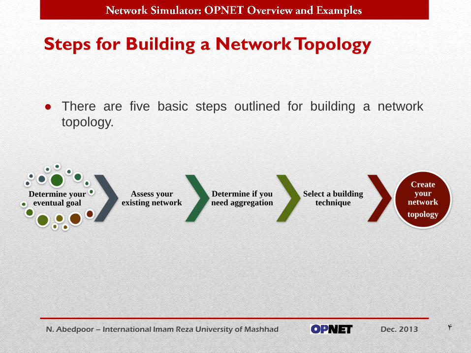
● There are five basic steps outlined for building a network
topology.
Steps for Building a Network Topology
N. Abedpoor – International Imam Reza University of Mashhad Dec. 2013 4
Determine your eventual goal
Assess your existing network
Determine if you need aggregation
Select a building technique
Create your
network
topology
● The choice of devices for constructing a network topology and
the method is very much a function of the goal of a simulation
study. Depending upon the context in which the software is
being used, you may represent the topology as a single path
between two devices, a partial topology with portions of the
network abstracted or a complete topology with every device
explicitly modeled.
Determine your eventual goal
N. Abedpoor – International Imam Reza University of Mashhad Dec. 2013 5
Determine your eventual goal
● only the infrastructure supporting traffic between two devices
of interest is represented
• For example, if the objective of using the software is to
analyze a client-server application
● The advantage of this topology is that it enhances the focus
of the study to the main objects of interest, i.e. the client and
the server. Since other devices are not explicitly modeled, the
simulation is very efficient. There is no loss of accuracy since
the effect of the remaining network on the client-server traffic
is taken into account. You can easily and quickly perform a
number of what-if scenarios by changing client/server
parameters or the amount of traffic in the intermediate
sections of the network.
Single Path
N. Abedpoor – International Imam Reza University of Mashhad Dec. 2013 6
Determine your eventual goal
● In certain situations, it may be important to represent portions
of the network in detail while abstracting other sections.
● For example, if the objective is to study the utilization of a
backbone, the backbone portion must be completely
represented. Other sections of the network may be abstracted.
However their effects should be captured when traffic
information is entered.
Partial Topology
N. Abedpoor – International Imam Reza University of Mashhad Dec. 2013 7
Determine your eventual goal
● A complete topology is necessary when a particular problem is
scaled across the network and it is important to identify the
impact of the problem on all devices involved.
● For example, if a new application is being deployed and the
objective of the simulation is to determine its impact on
intermediate network devices, it may be important to model
the complete topology.
● Complete topologies may also be used when the objective of
the study is to move a server to various prospective locations
and study the impact of each choice on network resources
(say link utilization).
Complete Topology
N. Abedpoor – International Imam Reza University of Mashhad Dec. 2013 8
Determine your eventual goal
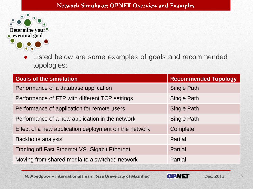
● Listed below are some examples of goals and recommended
topologies:
N. Abedpoor – International Imam Reza University of Mashhad Dec. 2013 9
Determine your eventual goal
Recommended Topology Goals of the simulation
Single Path Performance of a database application
Single Path Performance of FTP with different TCP settings
Single Path Performance of application for remote users
Single Path Performance of a new application in the network
Complete Effect of a new application deployment on the network
Partial Backbone analysis
Partial Trading off Fast Ethernet VS. Gigabit Ethernet
Partial Moving from shared media to a switched network
● Before beginning construction the final topology, it is important to
have a complete picture of the existing network in the form of a
drawing or a map. It is important to identify all existing devices, their role, and the protocols that are running in the existing network. It is
also important to identify the flows and traffic patterns in your
existing network.
● Consider the following questions:
• 1. Is the network flat (predominantly switched) or segmented
(routed)?
• 2. Where are the main servers located (WWW server, database
server etc.)?
• 3. What is the main traffic flow (users accessing the database
server, traffic through a firewall etc.)?
• 4. What are the sources of broadcast and multicast traffic?
Assess your existing network
N. Abedpoor – International Imam Reza University of Mashhad Dec. 2013 10
Assess your existing network
● Before performing the final steps in generating a topology, it is
important to determine if you can aggregate portions of the network.
● Aggregation can be performed at the segment level (LAN segment)
or at the subnet level (IP subnet).
● Portions of the network, which are outside the corporate control such
as the Internet or the carriers, can also be represented as simple
"cloud" objects with the appropriate latencies.
● Examples of the above are illustrated graphically next slides:
Determine if you need aggregation
N. Abedpoor – International Imam Reza University of Mashhad Dec. 2013 11
Determine if you need aggregation
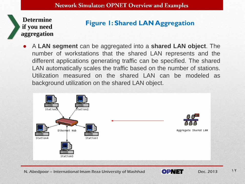
● A LAN segment can be aggregated into a shared LAN object. The
number of workstations that the shared LAN represents and the
different applications generating traffic can be specified. The shared
LAN automatically scales the traffic based on the number of stations.
Utilization measured on the shared LAN can be modeled as
background utilization on the shared LAN object.
Figure 1: Shared LAN Aggregation
N. Abedpoor – International Imam Reza University of Mashhad Dec. 2013 12
Determine if you need aggregation
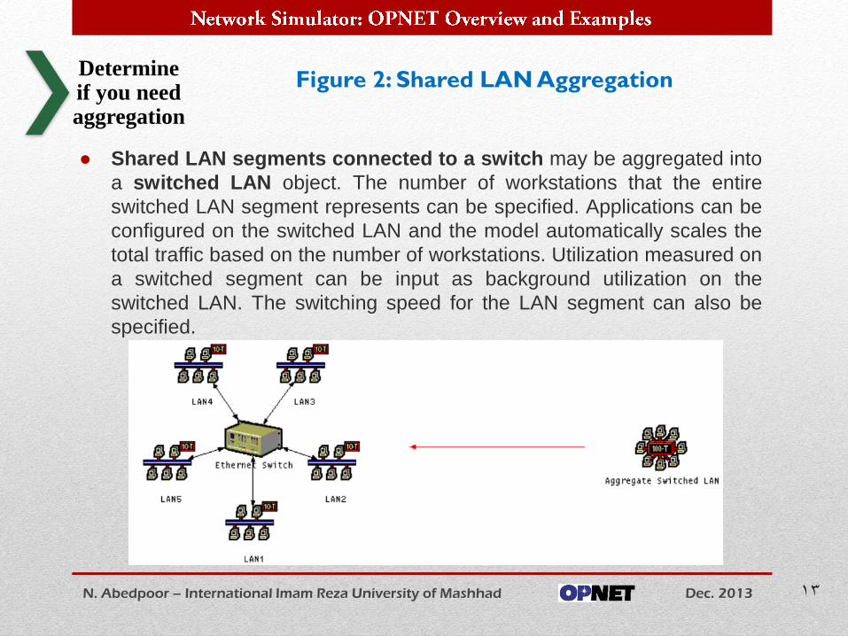
● Shared LAN segments connected to a switch may be aggregated into
a switched LAN object. The number of workstations that the entire
switched LAN segment represents can be specified. Applications can be
configured on the switched LAN and the model automatically scales the
total traffic based on the number of workstations. Utilization measured on
a switched segment can be input as background utilization on the
switched LAN. The switching speed for the LAN segment can also be
specified.
Figure 2: Shared LAN Aggregation
N. Abedpoor – International Imam Reza University of Mashhad Dec. 2013 13
Determine if you need aggregation
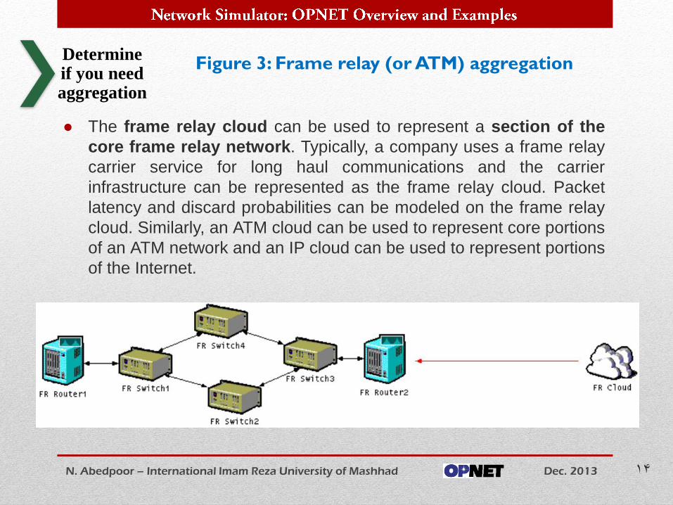
● The frame relay cloud can be used to represent a section of the
core frame relay network. Typically, a company uses a frame relay
carrier service for long haul communications and the carrier
infrastructure can be represented as the frame relay cloud. Packet
latency and discard probabilities can be modeled on the frame relay
cloud. Similarly, an ATM cloud can be used to represent core portions
of an ATM network and an IP cloud can be used to represent portions
of the Internet.
Figure 3: Frame relay (or ATM) aggregation
N. Abedpoor – International Imam Reza University of Mashhad Dec. 2013 14
Determine if you need aggregation
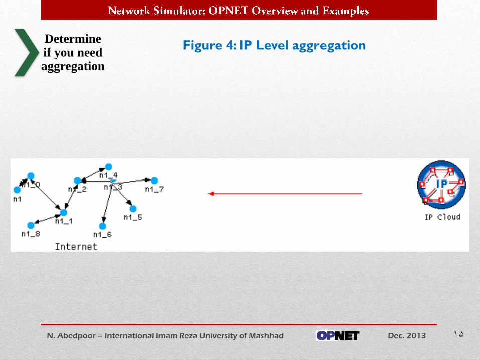
Figure 4: IP Level aggregation
N. Abedpoor – International Imam Reza University of Mashhad Dec. 2013 15
Determine if you need aggregation
● Topologies can be created manually or automatically through a
process of importing from tools that perform auto-discovery.
● Topologies can be constructed automatically from router configuration files and text/XML files as well.
Each one of these techniques is discussed in detail below.
● Direct Import
● The software supports importing topologies directly from a number of
vendor products. Each import procedure varies slightly based on the
information obtained from the vendor products. Refer to the product
documentation for details on the import procedure.
Select a technique for creating the topology
N. Abedpoor – International Imam Reza University of Mashhad Dec. 2013 16
Select a building
technique
• The VNE Server Environment
The OPNET VNE (Virtual Network Environment) Server product
provides an on-line, continuously valid, integrated view of your network.
VNE Server collects network data from disparate sources, and
intelligently merges this information to create a unified network
representation that can be used for network planning, engineering, and
operations.
Designed for openness, VNE Server is a user-extensible solution that
can encompass virtually any data source. VNE Server provides a
complete, architected approach for managing network information.
• Vendor Products
You can import from vendor products such as HP Network Node
Manager or Tivoli Netview. Refer to the product documentation for the
complete list of supported vendor products and procedures on how to
import from these products.
N. Abedpoor – International Imam Reza University of Mashhad Dec. 2013 17
Select a building
technique
• Text/XML Files
OPNET supports text-based or XML-based topology import. These
text/XML files have a specific format that can be found in the product
documentation. Geographic location information can be supplied in
these files.
• Router Configurations
OPNET supports import of router configuration files. Geographic location
information can be supplied with the router configurations. When you
use router configuration files, the topology that is created will have
attributes that control routing behavior specified based on the contents
of the router configuration files.
N. Abedpoor – International Imam Reza University of Mashhad Dec. 2013 18
Select a building
technique
The key features of the import process:
● The import preserves the network layout and hierarchy. The
relative positioning of objects is preserved. If objects are within subnets, the software will create subnets and place objects within them.
● Devices are mapped accurately to the model library. The software maintains a large database of device models (e.g. routers, switches, servers etc.) and their characteristics. During import, devices are identified based on their function and vendor.
● Import provides aggregation. The topology can be imported with LAN level aggregation, IP segment level aggregation or no aggregation at all.
● A Question/Answer database provides a method for dealing with unmanaged devices in case of import from HP Network Node Manager.
● Import can repair structural defects in the network.
N. Abedpoor – International Imam Reza University of Mashhad Dec. 2013 19
Select a building
technique
● Manual Construction
● Manual construction can be used when the topology is simple (in
terms of number of objects and complexity of interconnection) or
when supporting tools that provide topology information for direct
import are not available.
● To build topologies by hand, the software provides a number of
object palettes that contain common network devices and links used
for interconnection. The software also provides a technique called
"Rapid Configuration" that allows you to quickly create standard
topologies (star, tree, bus, mesh, etc.) containing many devices with
a few clicks. Once a topology has been created by hand, the
software provides features that allow the user to select a large
number of objects and apply attribute values in one operation.
Consistency checking is provided to ensure that links are accurate
and the interconnected devices are compatible.
N. Abedpoor – International Imam Reza University of Mashhad Dec. 2013 20
Select a building
technique
● Once the steps above have been completed, you can build
the network topology.
● The link consistency check must be executed to ensure that
the topology is accurate and there are no disconnected links.
● When the topology construction is complete, you can specify
attribute values on devices and run simulations. Some
features that are useful for this purpose are listed below.
N. Abedpoor – International Imam Reza University of Mashhad Dec. 2013 21
Create the
topology
Create the Topology
Details about these features may be found in the
software documentation.
● Find node: Allows the user to locate any node by name across the
network. LAN objects or any objects that represent many devices can
be configured with the names of individual members that they
represent (aliases). The find node utility also locates a device by its
alias.
● Logical object selection: Objects can be selected based on their
type or any of their attribute settings. Selection sets can be retained
for further selection.
● Applying changes to selected objects: Changes to attribute values
for objects selected manually or using the find/logical object selection
command can be applied with a single click.
N. Abedpoor – International Imam Reza University of Mashhad Dec. 2013 22
Create the
topology
Details about these features may be found in the
software documentation.
● Configuring attributes: Attributes can be configured to represent
characteristics of the device. Protocol parameters can also be tuned.
● Selecting advanced models that contain many attributes: Models
are divided into a three-tier structure: advanced, intermediate and
final. Advanced models contain numerous attributes that can be
tuned based on the different protocols they contain. Intermediate
models contain a subset of the advanced model attributes and Final
models contain only very basic attributes that have to be configured
by the user.
N. Abedpoor – International Imam Reza University of Mashhad Dec. 2013 23
Create the
topology
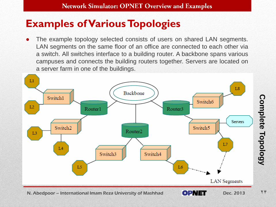
● The example topology selected consists of users on shared LAN segments.
LAN segments on the same floor of an office are connected to each other via
a switch. All switches interface to a building router. A backbone spans various
campuses and connects the building routers together. Servers are located on
a server farm in one of the buildings.
Examples of Various Topologies
N. Abedpoor – International Imam Reza University of Mashhad Dec. 2013 24
Co
mp
lete
To
po
log
y
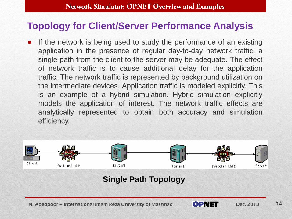
● If the network is being used to study the performance of an existing
application in the presence of regular day-to-day network traffic, a
single path from the client to the server may be adequate. The effect
of network traffic is to cause additional delay for the application
traffic. The network traffic is represented by background utilization on
the intermediate devices. Application traffic is modeled explicitly. This
is an example of a hybrid simulation. Hybrid simulation explicitly
models the application of interest. The network traffic effects are
analytically represented to obtain both accuracy and simulation
efficiency.
Topology for Client/Server Performance Analysis
N. Abedpoor – International Imam Reza University of Mashhad Dec. 2013 25
Single Path Topology
● If the network is used to study application deployment, it is
important to represent all the traffic flows from all clients to the
servers. Since the objective is to study application response
time and the effect of this application on the switches and
routers, it is not important to model in full detail of each LAN
segment. LANs may be aggregated into shared LAN objects
with the appropriate number of workstations. Note that the
LAN object will automatically scale the traffic based on the
number of workstations. The flows across the switches and
routers must be modeled explicitly as the effect of the new
application on such devices is important in the study.
Topology for Application Deployment
N. Abedpoor – International Imam Reza University of Mashhad Dec. 2013 26
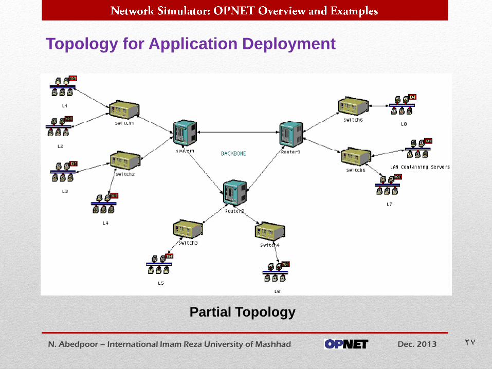
Topology for Application Deployment
N. Abedpoor – International Imam Reza University of Mashhad Dec. 2013 27
Partial Topology
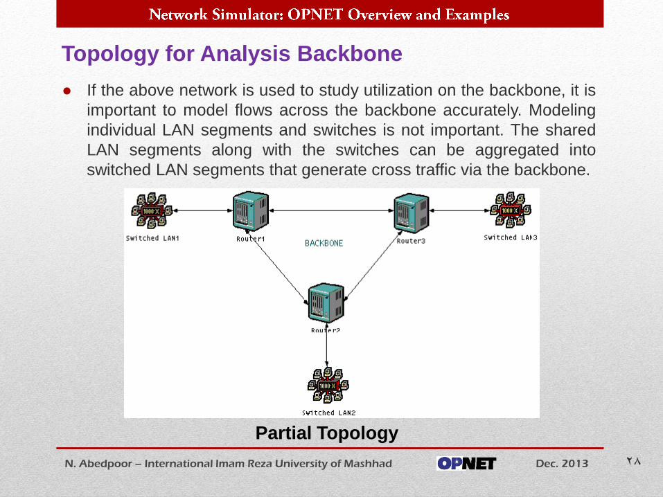
● If the above network is used to study utilization on the backbone, it is
important to model flows across the backbone accurately. Modeling
individual LAN segments and switches is not important. The shared
LAN segments along with the switches can be aggregated into
switched LAN segments that generate cross traffic via the backbone.
Topology for Analysis Backbone
N. Abedpoor – International Imam Reza University of Mashhad Dec. 2013 28
Partial Topology
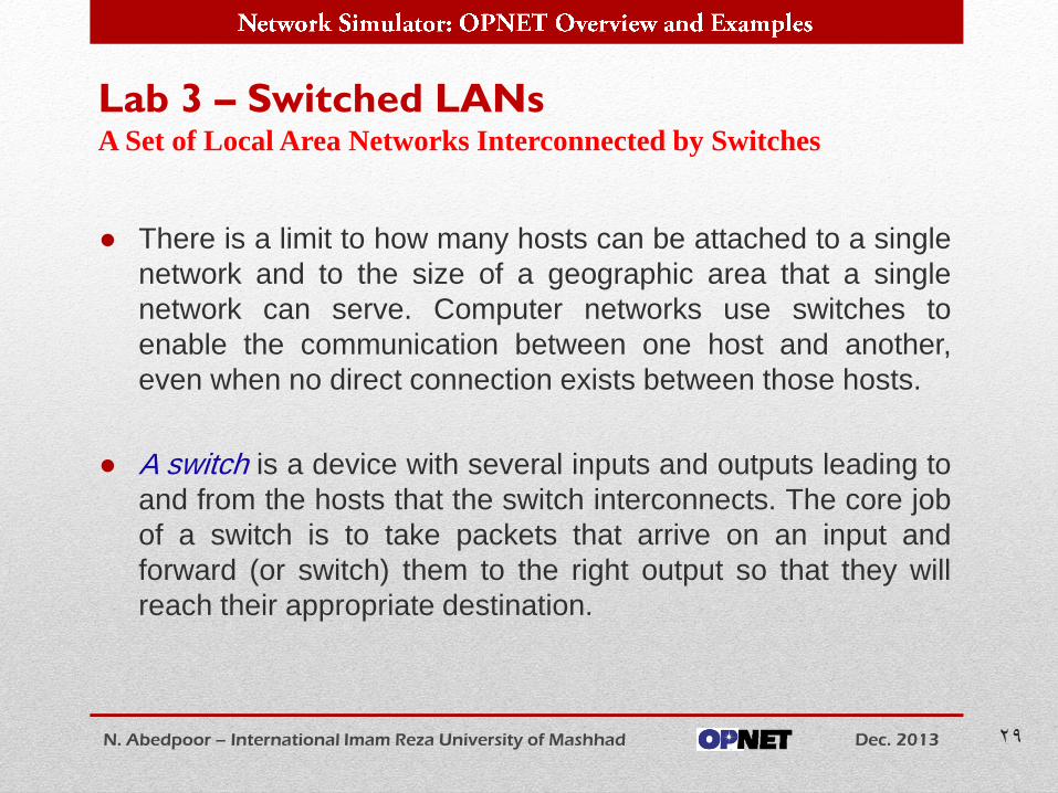
● There is a limit to how many hosts can be attached to a single
network and to the size of a geographic area that a single
network can serve. Computer networks use switches to
enable the communication between one host and another,
even when no direct connection exists between those hosts.
● A switch is a device with several inputs and outputs leading to
and from the hosts that the switch interconnects. The core job
of a switch is to take packets that arrive on an input and
forward (or switch) them to the right output so that they will
reach their appropriate destination.
Lab 3 – Switched LANs
N. Abedpoor – International Imam Reza University of Mashhad Dec. 2013 29
A Set of Local Area Networks Interconnected by Switches
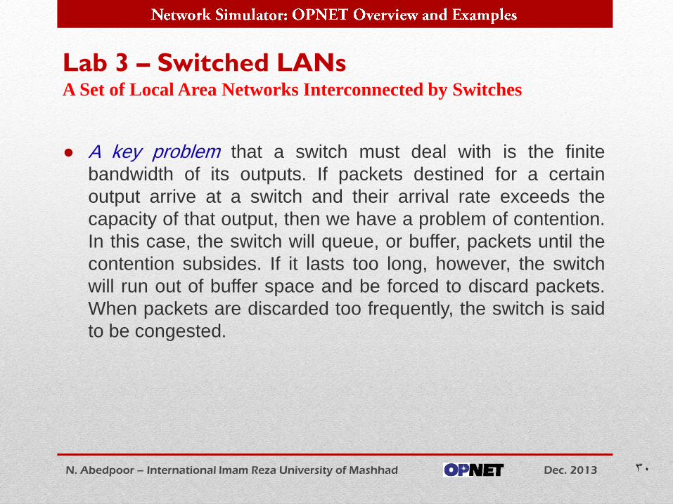
● A key problem that a switch must deal with is the finite
bandwidth of its outputs. If packets destined for a certain
output arrive at a switch and their arrival rate exceeds the
capacity of that output, then we have a problem of contention.
In this case, the switch will queue, or buffer, packets until the
contention subsides. If it lasts too long, however, the switch
will run out of buffer space and be forced to discard packets.
When packets are discarded too frequently, the switch is said
to be congested.
Lab 3 – Switched LANs
N. Abedpoor – International Imam Reza University of Mashhad Dec. 2013 30
A Set of Local Area Networks Interconnected by Switches
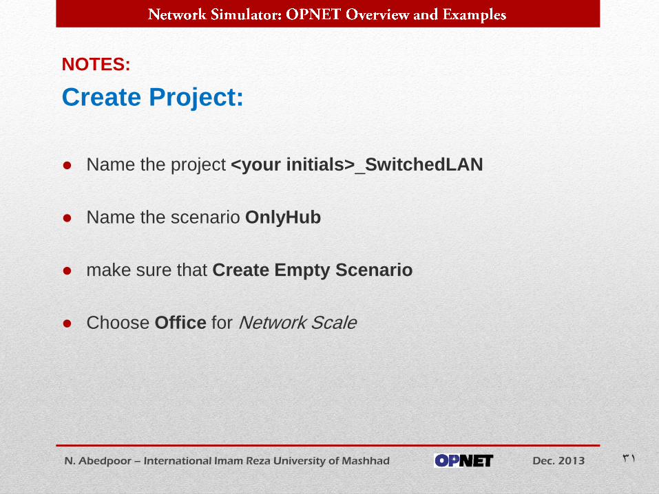
NOTES:
Create Project:
● Name the project <your initials>_SwitchedLAN
● Name the scenario OnlyHub
● make sure that Create Empty Scenario
● Choose Office for Network Scale
N. Abedpoor – International Imam Reza University of Mashhad Dec. 2013 31
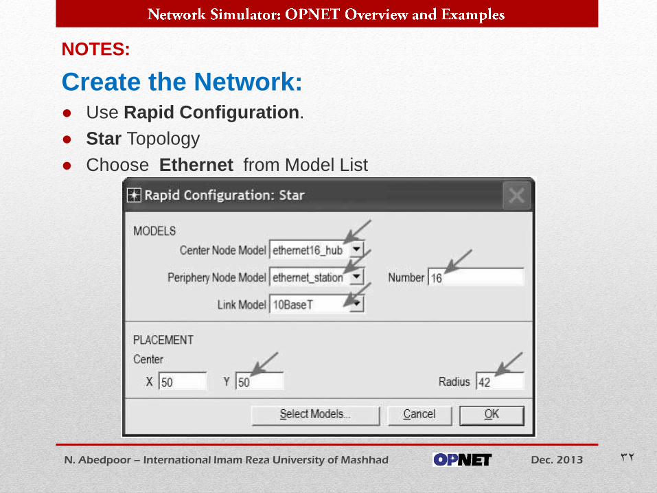
NOTES:
Create the Network: ● Use Rapid Configuration.
● Star Topology
● Choose Ethernet from Model List
N. Abedpoor – International Imam Reza University of Mashhad Dec. 2013 32
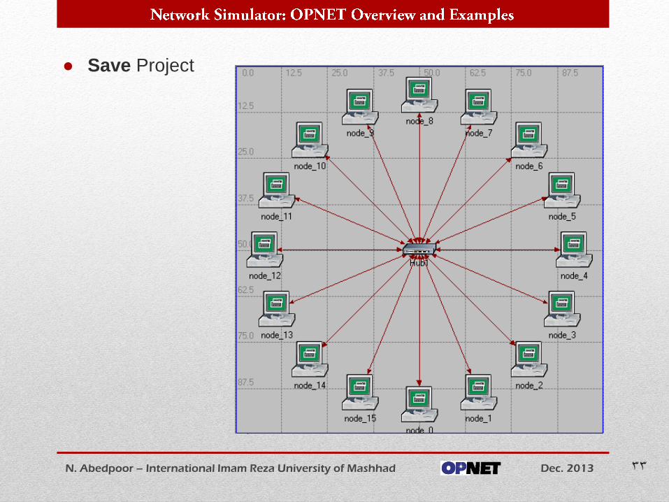
● Save Project
N. Abedpoor – International Imam Reza University of Mashhad Dec. 2013 33
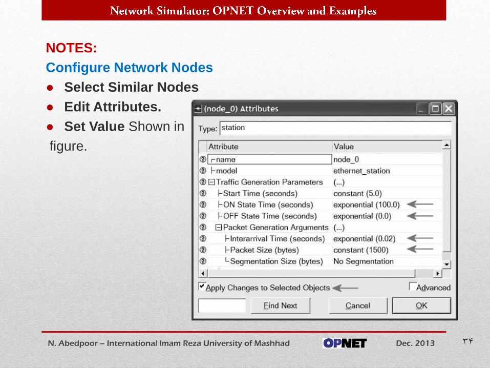
NOTES:
Configure Network Nodes
● Select Similar Nodes
● Edit Attributes.
● Set Value Shown in
figure.
N. Abedpoor – International Imam Reza University of Mashhad Dec. 2013 34
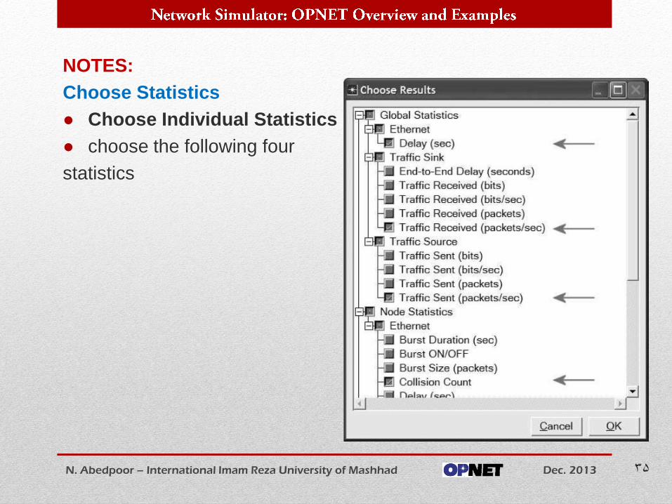
NOTES:
Choose Statistics
● Choose Individual Statistics
● choose the following four
statistics
N. Abedpoor – International Imam Reza University of Mashhad Dec. 2013 35
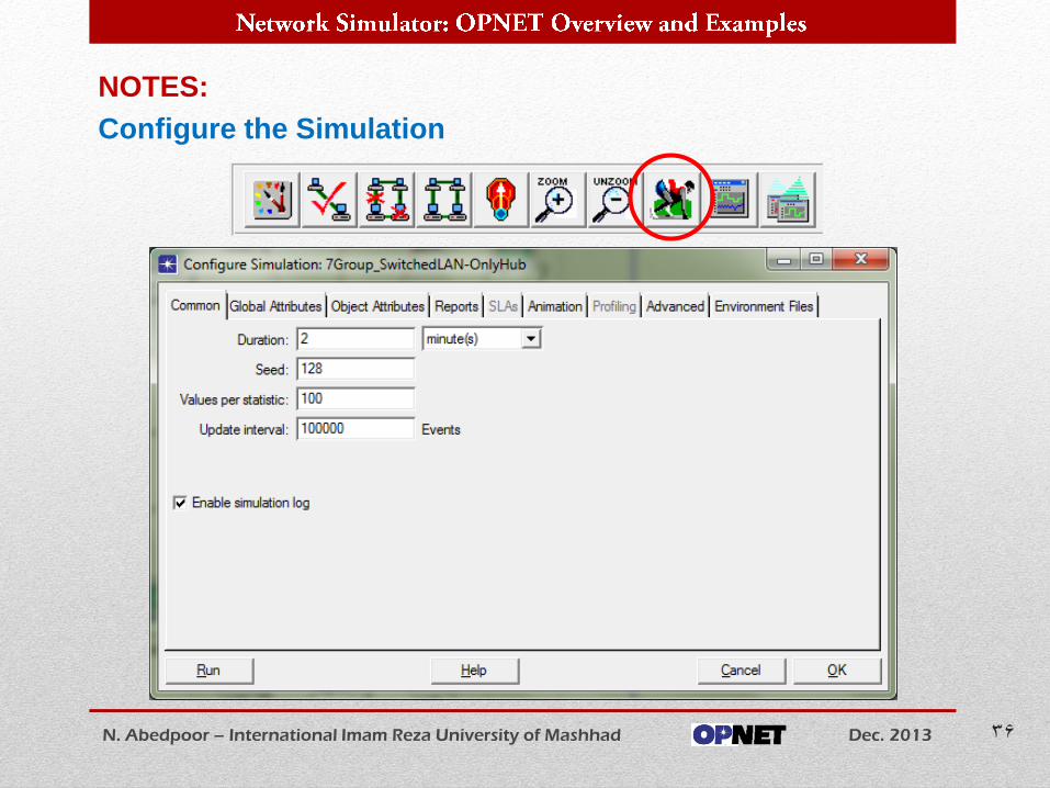
NOTES:
Configure the Simulation
N. Abedpoor – International Imam Reza University of Mashhad Dec. 2013 36
NOTES:
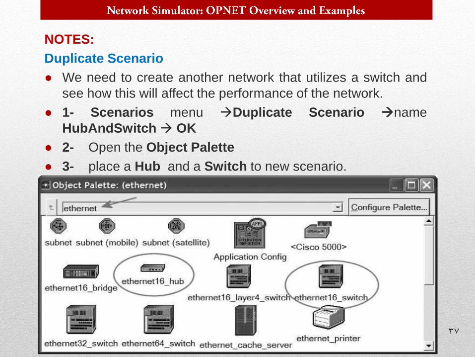
Duplicate Scenario
● We need to create another network that utilizes a switch and
see how this will affect the performance of the network.
● 1- Scenarios menu Duplicate Scenario name
HubAndSwitch OK
● 2- Open the Object Palette
● 3- place a Hub and a Switch to new scenario.
N. Abedpoor – International Imam Reza University of Mashhad Dec. 2013 37
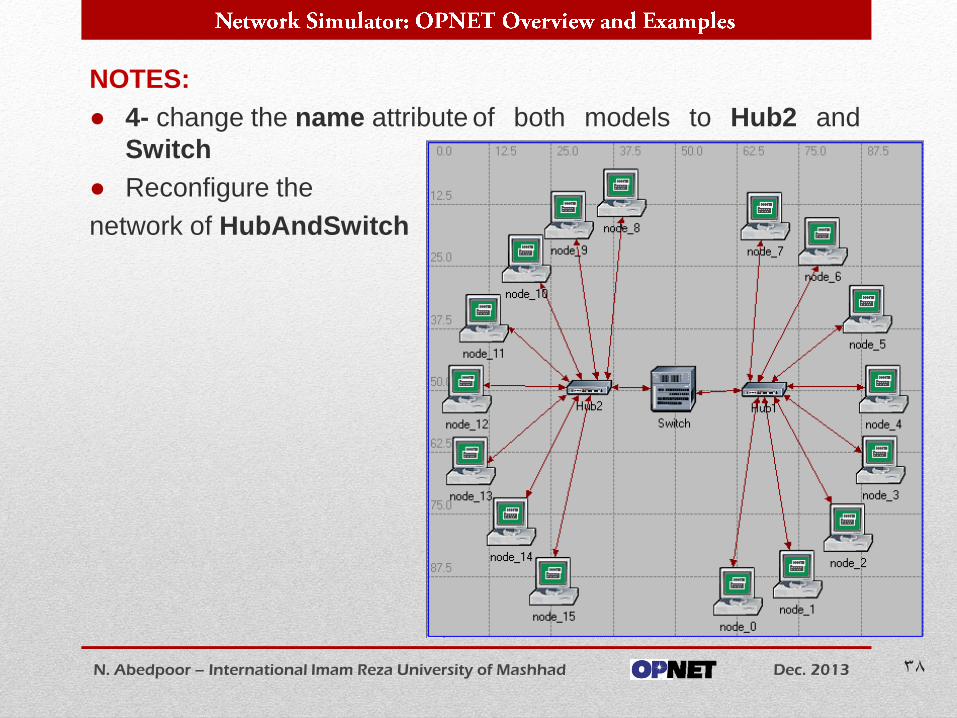
NOTES:
● 4- change the name attribute of both models to Hub2 and
Switch
● Reconfigure the
network of HubAndSwitch
N. Abedpoor – International Imam Reza University of Mashhad Dec. 2013 38
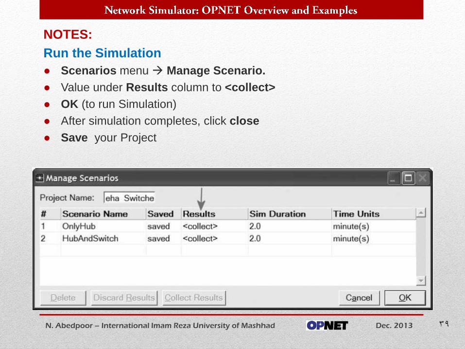
NOTES:
Run the Simulation
● Scenarios menu Manage Scenario.
● Value under Results column to <collect>
● OK (to run Simulation)
● After simulation completes, click close
● Save your Project
N. Abedpoor – International Imam Reza University of Mashhad Dec. 2013 39
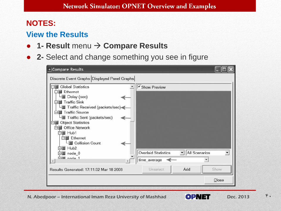
NOTES:
View the Results
● 1- Result menu Compare Results
● 2- Select and change something you see in figure
N. Abedpoor – International Imam Reza University of Mashhad Dec. 2013 40
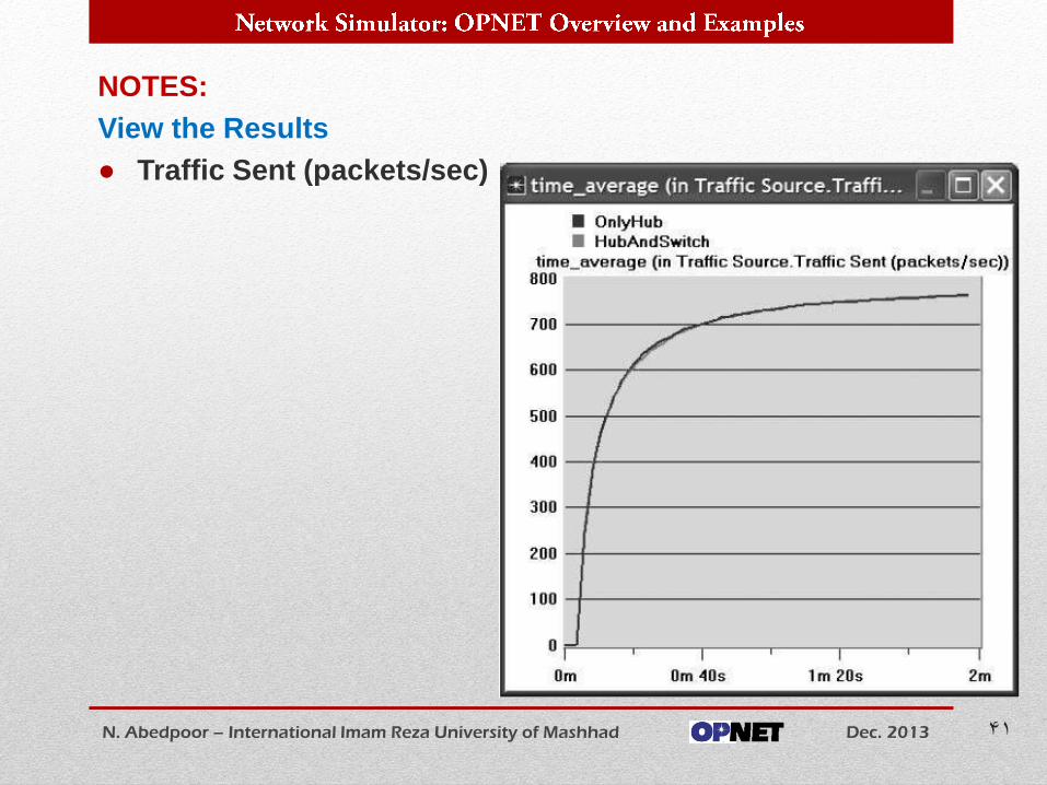
NOTES:
View the Results
● Traffic Sent (packets/sec)
N. Abedpoor – International Imam Reza University of Mashhad Dec. 2013 41
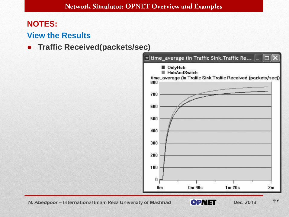
NOTES:
View the Results
● Traffic Received(packets/sec)
N. Abedpoor – International Imam Reza University of Mashhad Dec. 2013 42
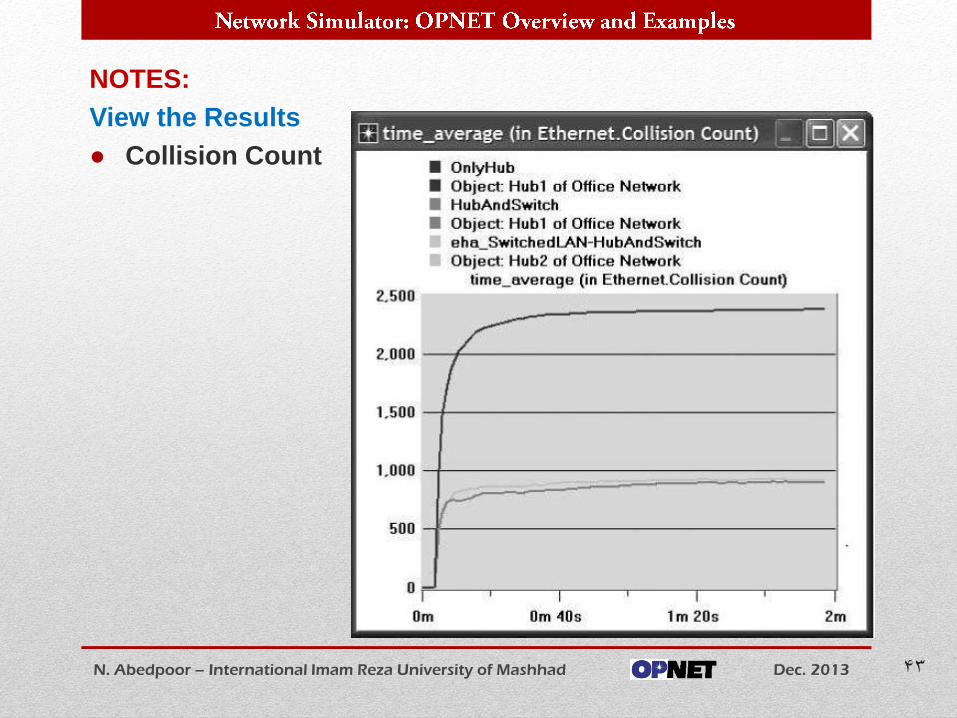
NOTES:
View the Results
● Collision Count
N. Abedpoor – International Imam Reza University of Mashhad Dec. 2013 43
Time to Believe yourself !!!
Start as professionals…
N. Abedpoor – International Imam Reza University of Mashhad Dec. 2013 44


![NET323 D: NETWORKS PROTOCOLS - WordPress.com · References 27 Cisco Packet Tracer Help Lab 3 : Switched LAN. [Online]. Available at: OPNET IT Guru Academy.(Accessed: 2015). Supported](https://img.pdfslide.net/doc/110x75/5af139a27f8b9abc788e2ab1/net323-d-networks-protocols-27-cisco-packet-tracer-help-lab-3-switched-lan.jpg)