Embed Size (px)
Citation preview
OPNET mobility simulation modelsPaolo Di Lorenzo, UoR
Introduction
The purpose of this document is to describe the full TCP/IP integration of local mobilityprotocols in a wireless LAN's environment using IEEE802.11 as wireless LAN's interface and
standard IEEE802.3 (Ethernet) for backbone routing.
This document will not deal with the local mobility protocol description (namely Cellular IP and
SIMPLE) giving for granted a thorough knowledge of both protocols. Anyway it will be pointed out
when the implemented models differ from the theoretical protocols. Further insights on both
protocols are available in the related drafts.
This paper is structured in three main sections: the first section will deal with the description of the
Cellular IP simulation, the second one with the SIMPLE integration and the third one with the
simulation results. Every network node will be described in its protocol stack approach, node model
interfaces and process model general description; this document will not try to explain the coding
itself nor every implementation detail since these details can be further investigated reading the
code which is somewhat documented.
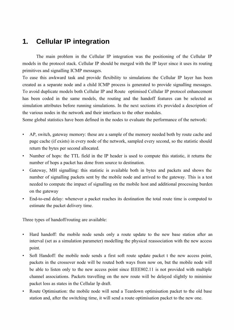
1. Cellular IP integration
The main problem in the Cellular IP integration was the positioning of the Cellular IP
models in the protocol stack. Cellular IP should be merged with the IP layer since it uses its routing
primitives and signalling ICMP messages.
To ease this awkward task and provide flexibility to simulations the Cellular IP layer has been
created as a separate node and a child ICMP process is generated to provide signalling messages.To avoid duplicate models both Cellular IP and Route optimised Cellular IP protocol enhancement
has been coded in the same models, the routing and the handoff features can be selected as
simulation attributes before running simulations. In the next sections it's provided a description of
the various nodes in the network and their interfaces to the other modules.
Some global statistics have been defined in the nodes to evaluate the performance of the network:
• AP, switch, gateway memory: these are a sample of the memory needed both by route cache andpage cache (if exists) in every node of the network, sampled every second, so the statistic should
return the bytes per second allocated.
• Number of hops: the TTL field in the IP header is used to compute this statistic, it returns thenumber of hops a packet has done from source to destination.
• Gateway, MH signalling: this statistic is available both in bytes and packets and shows thenumber of signalling packets sent by the mobile node and arrived to the gateway. This is a test
needed to compute the impact of signalling on the mobile host and additional processing burden
on the gateway
• End-to-end delay: whenever a packet reaches its destination the total route time is computed toestimate the packet delivery time.
Three types of handoff/routing are available:
• Hard handoff: the mobile node sends only a route update to the new base station after aninterval (set as a simulation parameter) modelling the physical reassociation with the new access
point.
• Soft Handoff: the mobile node sends a first soft route update packet t the new access point,packets in the crossover node will be routed both ways from now on, but the mobile node will
be able to listen only to the new access point since IEEE802.11 is not provided with multiple
channel associations. Packets travelling on the new route will be delayed slightly to minimise
packet loss as states in the Cellular Ip draft.
• Route Optimisation: the mobile node will send a Teardown optimisation packet to the old basestation and, after the switching time, it will send a route optimisation packet to the new one.

1.1 ICMP model
An important task was the creation in every node, of various kind of signalling messages.
Without route optimisation, only mobile nodes and access points were responsible for the creation
of signalling messages, but the introduction of route optimisation has made every node as acandidate for signal sending.
Since Opnet defined ICMP process only provided ping and ping reply messages, an additional
process has been developed to explicitly handle all Cellular IP signalling message types. The
process creates ICMP packets to carry signalling information and encapsulates them in a IP packet
to be routed in the network.
This process is invoked as a child process from the Cellular IP module whenever a new signalling
message needs be sent. The invocation of this process is quite straightforward, a shared memory
Figure 1: ICMP child process model
handle is defined in the parent process for interprocess communication; the child gets the message
type, the source and destination address and other fields if needed and returns the packet to theparent process.
Statistics have been defined to keep track of the different kind of signalling generated both in bytes
and in packets per second.
1.2 Cellular IP workstation node model
In the workstation node model the Cellular IP layer has been placed just below IP, this was
necessary to permit signalling IP (ICMP) packet's address to be resolved correctly in the ARP layer.
OPNET provides two way of using ARP: one is to let ARP messages be created and sent in the
network to resolve addresses, an IP packet will not be sent to the layer below unless it's IP address
is resolved; the other way is to simulate ARP signalling, since ARP messages do not contribute
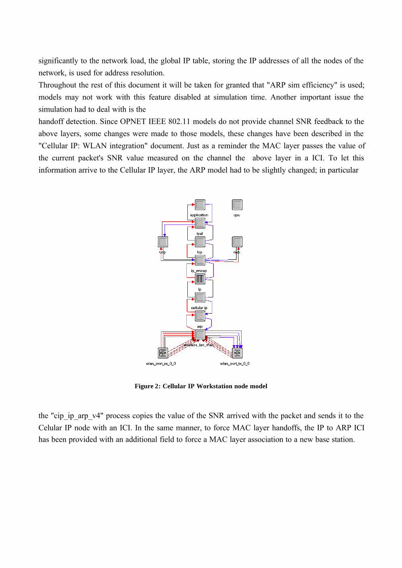
significantly to the network load, the global IP table, storing the IP addresses of all the nodes of the
network, is used for address resolution.
Throughout the rest of this document it will be taken for granted that "ARP sim efficiency" is used;
models may not work with this feature disabled at simulation time. Another important issue the
simulation had to deal with is the
handoff detection. Since OPNET IEEE 802.11 models do not provide channel SNR feedback to the
above layers, some changes were made to those models, these changes have been described in the
"Cellular IP: WLAN integration" document. Just as a reminder the MAC layer passes the value of
the current packet's SNR value measured on the channel the above layer in a ICI. To let this
information arrive to the Cellular IP layer, the ARP model had to be slightly changed; in particular
Figure 2: Cellular IP Workstation node model
the "cip_ip_arp_v4" process copies the value of the SNR arrived with the packet and sends it to the
Celular IP node with an ICI. In the same manner, to force MAC layer handoffs, the IP to ARP ICIhas been provided with an additional field to force a MAC layer association to a new base station.

Of course to keep the IP to ARP interprocess communication, the Cellular IP layer copies the IP ICI
(used mainly to pass the next hop address to the ARP module for address resolution) and sends it
with the packet to the ARP layer.
Figure 3: Cellular IP workstation process model
1.3 Cellular IP access point and switch node model
Both the access point and the switch node model will be described in this section since they share
some common characteristics.
The access point has been modelled with two network interfaces, one (IEEE 802.11) on the wireless
part of the network and a standard Ethernet interface on the wired part.
Figure 4: Cellular IP Access point node model
The Cellular IP node communicates with the MAC layer with an ICI used to pass the MAC address
of the next destination node, which is taken in the Cellular IP route cache, whenever a packet
arrives to a MAC interface the packet is passed to the Cellular IP layer together with an ICI carrying

the source MAC address, this information coupled with the stream the packet came from is used to
update the Route Cache of the node.
The switch node model has no wireless interface but has five Ethernet interfaces, one of these
interfaces is reserved for uplink transmission and the other are used for downlink ones. The
transmission rate in the core network is set to 10Mbit using 10BaseT links. Switches can have Page
Caches while access points can only have Route Caches.
Figure 5: Cellular IP Switch node model
1.4 Cellular IP gateway node model
The gateway node model is quite complicated because there were many issues that had to be
dealt with to make it work properly.

It is made up of 8 Serial Line IP transmitter/receiver pair used to communicate outside the network
and three Ethernet interfaces for communications inside the network.
The Cellular IP protocol has been put together with the ARP protocol in a single module; this has
been necessary to have multiple Ethernet interfaces to the network without having different IP
addresses for each interface.
Whenever a packet has an IP address not present in the node’s Page cache, the packet is sent to the
IP layer which will route it to the appropriate destination, on the other hand when a packet comes in
from an outside network it is passed to the Cellular IP/ARP module; here the destination address is
searched in the Route and Page caches and, if found, address resolution is performed to get the
destination node’s MAC address.
Figure 6: Cellular IP Gateway node model
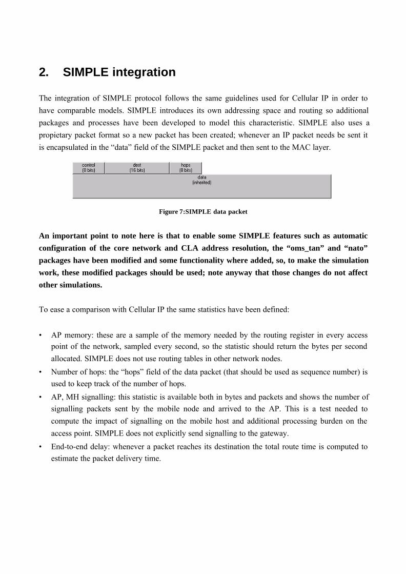
2. SIMPLE integration
The integration of SIMPLE protocol follows the same guidelines used for Cellular IP in order to
have comparable models. SIMPLE introduces its own addressing space and routing so additional
packages and processes have been developed to model this characteristic. SIMPLE also uses a
propietary packet format so a new packet has been created; whenever an IP packet needs be sent it
is encapsulated in the “data” field of the SIMPLE packet and then sent to the MAC layer.
Figure 7:SIMPLE data packet
An important point to note here is that to enable some SIMPLE features such as automatic
configuration of the core network and CLA address resolution, the “oms_tan” and “nato”
packages have been modified and some functionality where added, so, to make the simulation
work, these modified packages should be used; note anyway that those changes do not affect
other simulations.
To ease a comparison with Cellular IP the same statistics have been defined:
• AP memory: these are a sample of the memory needed by the routing register in every accesspoint of the network, sampled every second, so the statistic should return the bytes per second
allocated. SIMPLE does not use routing tables in other network nodes.
• Number of hops: the “hops” field of the data packet (that should be used as sequence number) isused to keep track of the number of hops.
• AP, MH signalling: this statistic is available both in bytes and packets and shows the number ofsignalling packets sent by the mobile node and arrived to the AP. This is a test needed to
compute the impact of signalling on the mobile host and additional processing burden on the
access point. SIMPLE does not explicitly send signalling to the gateway.
• End-to-end delay: whenever a packet reaches its destination the total route time is computed toestimate the packet delivery time.
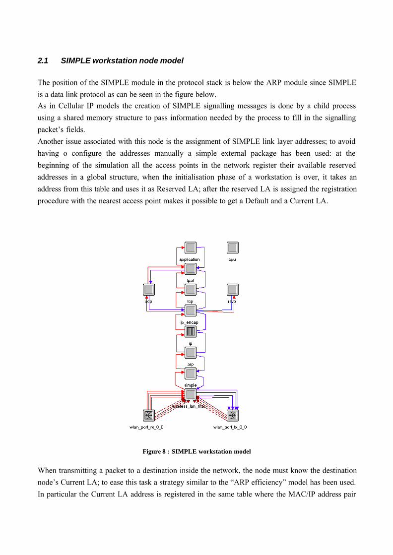
2.1 SIMPLE workstation node model
The position of the SIMPLE module in the protocol stack is below the ARP module since SIMPLE
is a data link protocol as can be seen in the figure below.As in Cellular IP models the creation of SIMPLE signalling messages is done by a child process
using a shared memory structure to pass information needed by the process to fill in the signalling
packet’s fields.
Another issue associated with this node is the assignment of SIMPLE link layer addresses; to avoid
having o configure the addresses manually a simple external package has been used: at the
beginning of the simulation all the access points in the network register their available reserved
addresses in a global structure, when the initialisation phase of a workstation is over, it takes an
address from this table and uses it as Reserved LA; after the reserved LA is assigned the registration
procedure with the nearest access point makes it possible to get a Default and a Current LA.
Figure 8 : SIMPLE workstation model
When transmitting a packet to a destination inside the network, the node must know the destination
node’s Current LA; to ease this task a strategy similar to the “ARP efficiency” model has been used.
In particular the Current LA address is registered in the same table where the MAC/IP address pair
is stored, so, when a node needs to send a packet, it resolves the MAC address of the destination
first and the resolves the CLA address.
Of course, upon handoffs the workstation changes the registered CLA to match the new one
assigned after a successful registration procedure.
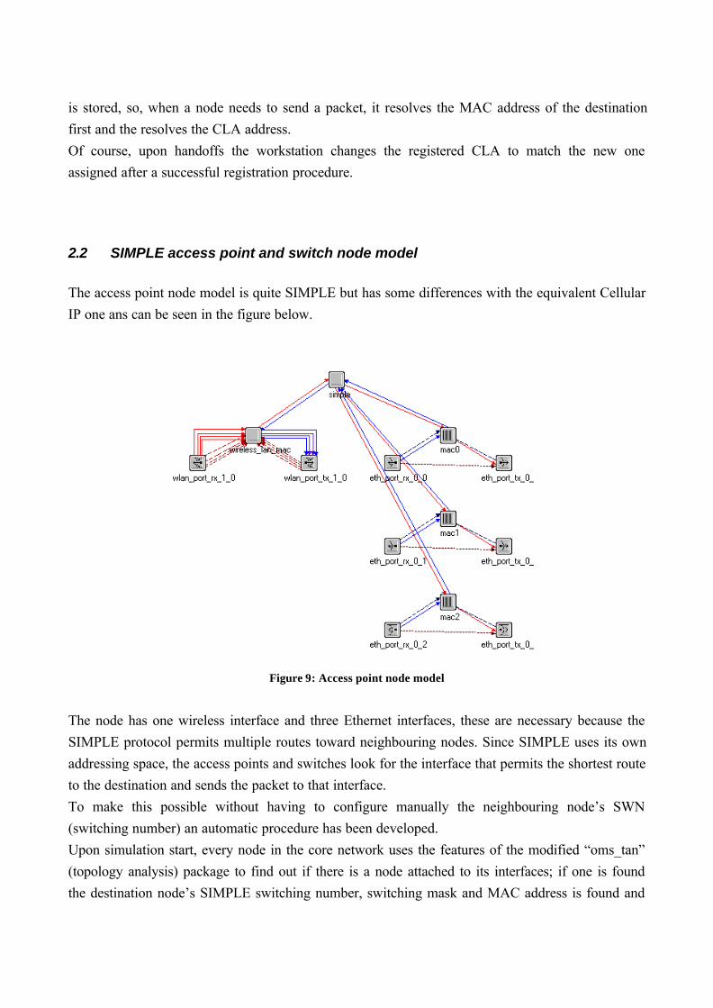
2.2 SIMPLE access point and switch node model
The access point node model is quite SIMPLE but has some differences with the equivalent Cellular
IP one ans can be seen in the figure below.
Figure 9: Access point node model
The node has one wireless interface and three Ethernet interfaces, these are necessary because the
SIMPLE protocol permits multiple routes toward neighbouring nodes. Since SIMPLE uses its own
addressing space, the access points and switches look for the interface that permits the shortest route
to the destination and sends the packet to that interface.
To make this possible without having to configure manually the neighbouring node’s SWN
(switching number) an automatic procedure has been developed.
Upon simulation start, every node in the core network uses the features of the modified “oms_tan”
(topology analysis) package to find out if there is a node attached to its interfaces; if one is found
the destination node’s SIMPLE switching number, switching mask and MAC address is found and
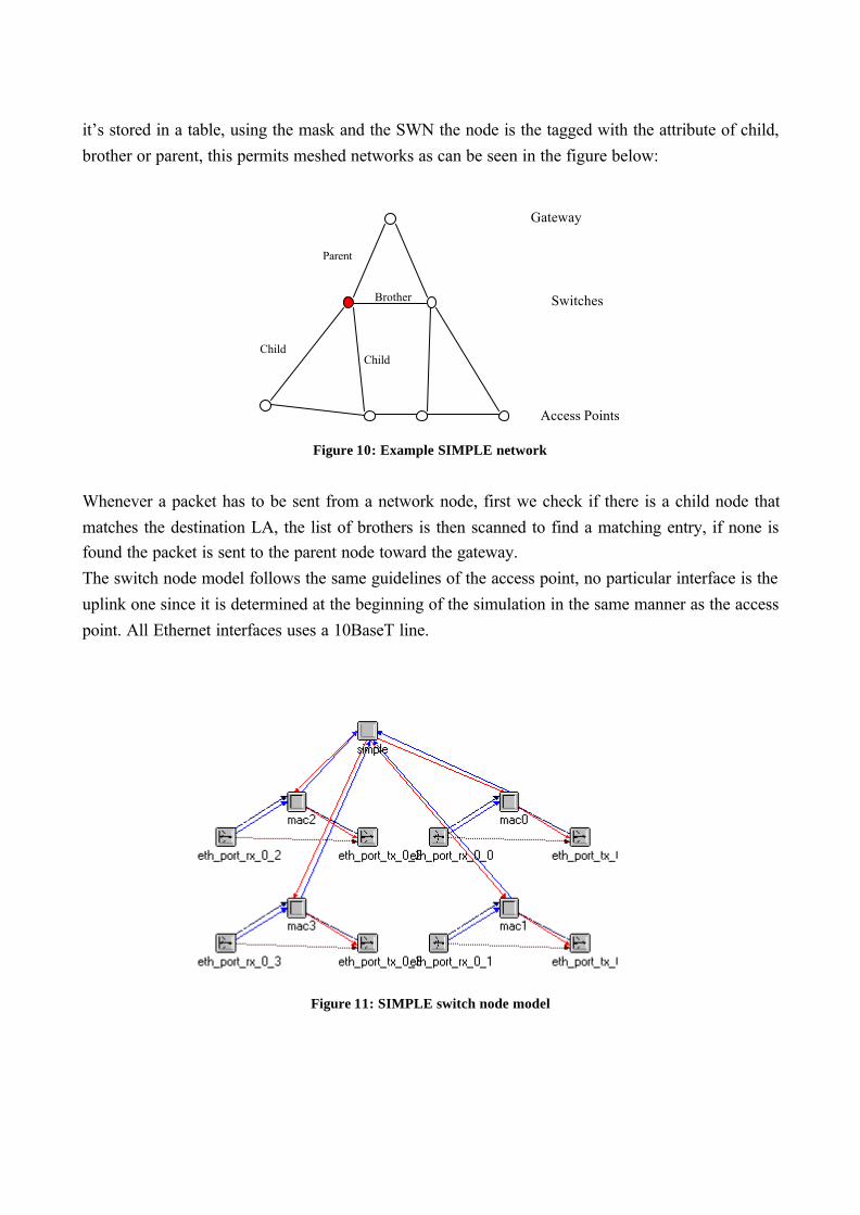
it’s stored in a table, using the mask and the SWN the node is the tagged with the attribute of child,
brother or parent, this permits meshed networks as can be seen in the figure below:
Figure 10: Example SIMPLE network
Whenever a packet has to be sent from a network node, first we check if there is a child node that
matches the destination LA, the list of brothers is then scanned to find a matching entry, if none isfound the packet is sent to the parent node toward the gateway.
The switch node model follows the same guidelines of the access point, no particular interface is the
uplink one since it is determined at the beginning of the simulation in the same manner as the access
point. All Ethernet interfaces uses a 10BaseT line.
Figure 11: SIMPLE switch node model
ChildChild
Parent
Brother
Access Points
Switches
Gateway

2.3 SIMPLE gateway node model
The gateway node model closely resembles the Cellular IP one; in particular the SIMPLE/ARP
protocols have been merged together in a single node model to permit multiple network interfaceswith a single IP address.
Figure 12: SIMPLE gateway node model

3. Simulations
3.1 Simulation scenario
To give a realistic approach to the network simulation a scenario where both inside traffic and
outside traffic are present has been created as can be seen in the figure below:
The first subnet placed in Rome is the network using local mobility protocols, it is connected to an
IP cloud node whose purpose is to model the Internet core network and another subnet placed in
London that is only made up of a gateway and an application server.
The two nodes on the upper left corner are needed to specify the application profile for the mobile
nodes and the server; in particular UDP based applications (voice, video) don’t need a server andare carried out between mobile nodes, TCP base application need a server to send their connection
requests and will connect to the server placed outside the network. These kind of profiles is better
suited to model real office environments where most of the traffic is outside the local network.
OPNET provides some typical application profiles that have been used in the mobile node’s
configuration as can be seen in the figure below; only video applications couldn’t be used for they
saturated the wireless channel when more than a few mobile nodes are in the same cell.
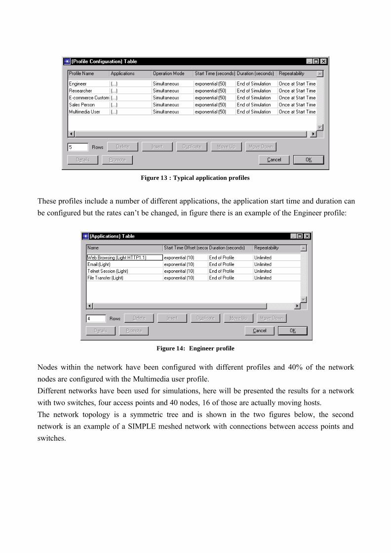
Figure 13 : Typical application profiles
These profiles include a number of different applications, the application start time and duration can
be configured but the rates can’t be changed, in figure there is an example of the Engineer profile:
Figure 14: Engineer profile
Nodes within the network have been configured with different profiles and 40% of the network
nodes are configured with the Multimedia user profile.
Different networks have been used for simulations, here will be presented the results for a network
with two switches, four access points and 40 nodes, 16 of those are actually moving hosts.
The network topology is a symmetric tree and is shown in the two figures below, the second
network is an example of a SIMPLE meshed network with connections between access points and
switches.

Figure 15: Cellular IP and SIMPLE tree network
Figure 16: SIMPLE mesh network

3.2 Simulation results
In this paragraph the simulation results will be presented, taking into account four parameter tharcharacterise a local routing protocol, in particular the number of hops in the network for a packet to
reach its destination node, the End to End delay that gives a measure of the congestion in the
network, the total memory resources needed by the protocol, and the signalling generated in the
network.
A point worth noticing is that due to the random spread of the applications the results and some
protocol improvements may give better or lesser performances where the simulation to be repeated,
to gain a better estimate of the results longer simulations should be run and a group and time
average should be computed from the results. For the purpose of this work, that is, to give an idea of
a protocol scalability, I think these results are somewhat reliable; to gain further insights
measurement should be carried out in real testbed environment with a sufficient number of hosts.
Number of hops
First some words on how this statistic is computed: for Cellular IP networks the TTL field in the IP
packet is used to keep track of the number of hops, since intermediate nodes (APs and switches) do
not have an IP layer the Cellular IP node decreases this field.
SIMPLE networks use the sequence number field to keep track of this parameter, since there’s no
way to keep track of he number of hops outside a SIMPLE network, packets coming from the
Internet are added a fixed number (3) of hops that if the number of hops from the server in the
outside network to the gateway in the SIMPLE network; this is kind of rough but was the only way
to keep the statistic significant.
The results can be seen in the two figure below, on the left there are the Cellular IP ones and on the
right the SIMPLE ones. As can be seen Route optimisation decreases the number of hops withrespect to Cellular IP where the number of hops is fixed since all packets must travel to the
gateway. The performance of SIMPLE is comparable to the Cellular IP with route optimisation
since the routing algorithm is the same while the new feature added to SIMPLE, the neighbour’s
table permits lower hops since the shortest route to destination is always used when one is found.
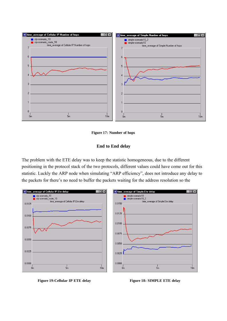
Figure 17: Number of hops
End to End delay
The problem with the ETE delay was to keep the statistic homogeneous, due to the differentpositioning in the protocol stack of the two protocols, different values could have come out for this
statistic. Luckly the ARP node when simulating “ARP efficiency”, does not introduce any delay to
the packets for there’s no need to buffer the packets waiting for the address resolution so the
Figure 19:Cellular IP ETE delay Figure 18: SIMPLE ETE delay

statistic is computed as the difference of the packet creation time (at the IP layer of the sending
node) and the packet arrival time (upon arrival in Cellular IP, after decapsulation but before sending
it to the ARP layer in SIMPLE).
As stated before the lower number of hops make it possible to have lower end to end delays in cases
where optimisation is done, again route optimised cellular IP and tree topology SIMPLE behave
more or less in the same way (note the different scales).
Memory resources
The total memory allocated is an average of the memory needed by the tables, either static or
dynamic necessary to the protocol.
While Cellular IP uses dynamic tables SIMPLE uses fixed length static tables in fact, as can be seen
in the figures the average memory is constant during the simulation. Route optimised Cellular IP
uses more memory than normal Cellular IP to store additional information in the route optimisation
structure.
It should be noted that the memory used for SIMPLE won’t change where the number of nodes in
the network to increase up to 64 mobile nodes.
Figure 21: Cellular IP node memory Figure 20: Cellular IP route optimised

Figure 22: SIMPLE memory
Figure 23: Cellular IP total memory
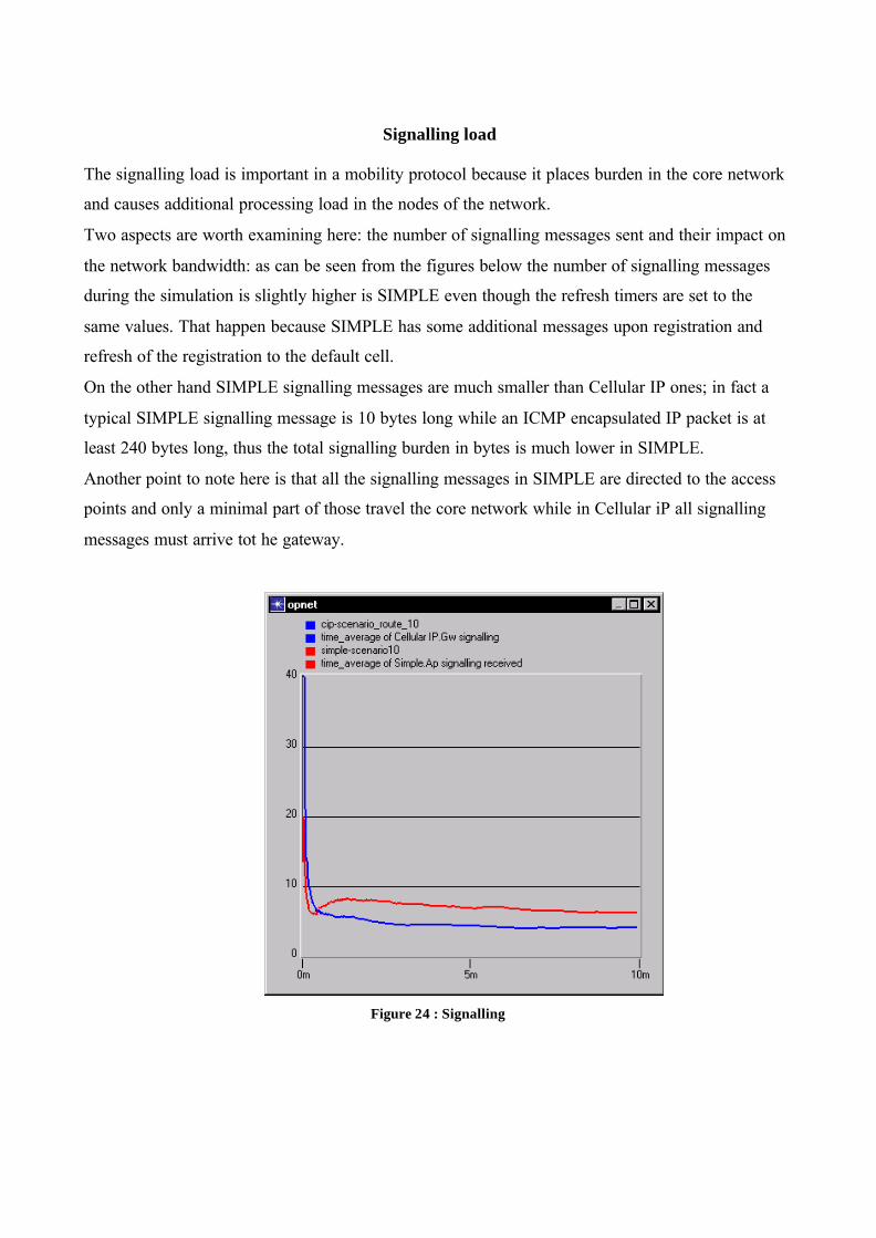
Signalling load
The signalling load is important in a mobility protocol because it places burden in the core network
and causes additional processing load in the nodes of the network.
Two aspects are worth examining here: the number of signalling messages sent and their impact on
the network bandwidth: as can be seen from the figures below the number of signalling messages
during the simulation is slightly higher is SIMPLE even though the refresh timers are set to the
same values. That happen because SIMPLE has some additional messages upon registration and
refresh of the registration to the default cell.
On the other hand SIMPLE signalling messages are much smaller than Cellular IP ones; in fact a
typical SIMPLE signalling message is 10 bytes long while an ICMP encapsulated IP packet is at
least 240 bytes long, thus the total signalling burden in bytes is much lower in SIMPLE.
Another point to note here is that all the signalling messages in SIMPLE are directed to the access
points and only a minimal part of those travel the core network while in Cellular iP all signalling
messages must arrive tot he gateway.
Figure 24 : Signalling
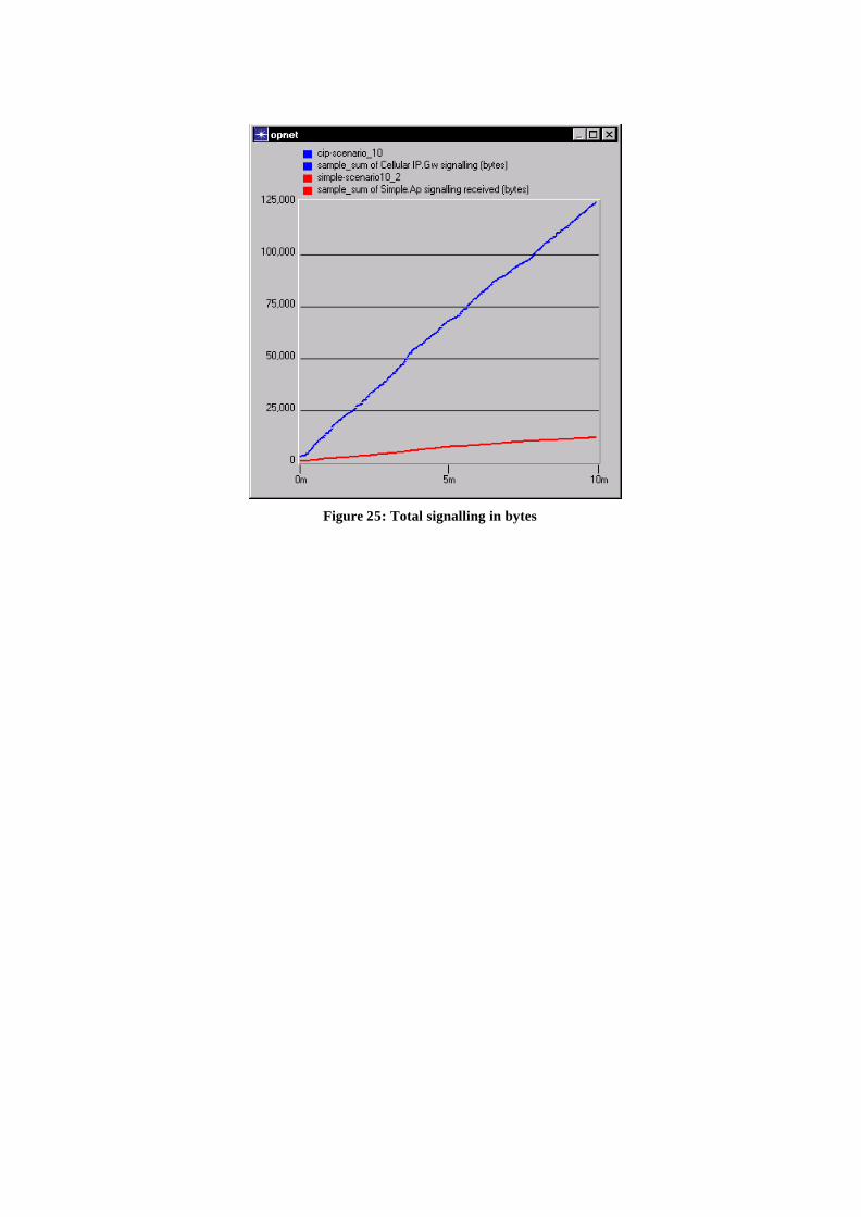
Figure 25: Total signalling in bytes