Embed Size (px)
Citation preview
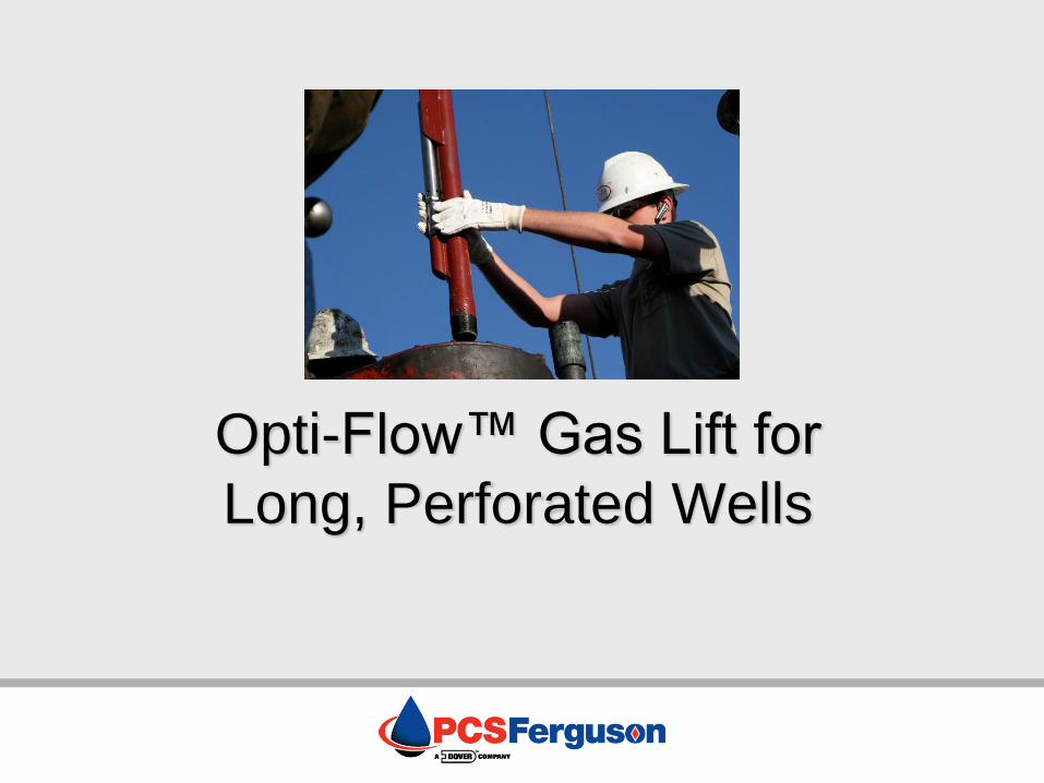
Opti-Flow™ Gas Lift for
Long, Perforated Wells

Property of PCS Ferguson. All content is confidential to PCS Ferguson and its respective partners.
Introduction
More wells being drilled and completed with long perforated intervals – deep verticals and long horizontals with multiple zones.
Insufficient velocities below the packer can cause liquid loading.
New innovations in gas lift make it a viable option for long perforated intervals.
Property of PCS Ferguson. All content is confidential to PCS Ferguson and its respective partners.
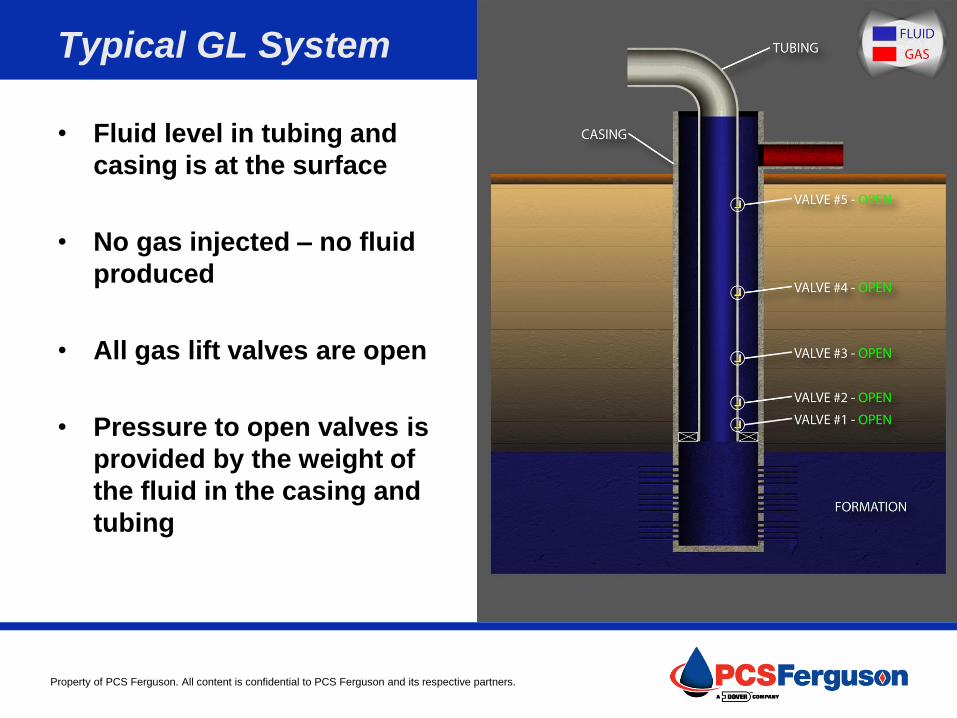
Typical GL System
• Fluid level in tubing and
casing is at the surface
• No gas injected – no fluid
produced
• All gas lift valves are open
• Pressure to open valves is
provided by the weight of
the fluid in the casing and
tubing

Property of PCS Ferguson. All content is confidential to PCS Ferguson and its respective partners.
Typical GL System
• Gas injection into casing
• Fluid U-tubes through all
open valves
• Fluids produced from
annulus only - pressure in
the wellbore at perfs is
greater than reservoir
pressure

Property of PCS Ferguson. All content is confidential to PCS Ferguson and its respective partners.
Typical GL System
• Fluid is unloaded to the top (#5) gas lift valve
• Fluid is aerated above this point in the tubing, decreasing flowing gradient
• Pressure is reduced at top valve, as well as all lower valves
• Unloading continues through lower valves

Property of PCS Ferguson. All content is confidential to PCS Ferguson and its respective partners.
Typical GL System
• Fluid level now below valve
#4 (second from top)
• Injection transfers to valve
#4 and pressure is lowered
• Casing pressure drops and
valve #5 closes
• Unloading continues
through lower valves

Property of PCS Ferguson. All content is confidential to PCS Ferguson and its respective partners.
Typical GL System
• Gas is injected through valve #4
• Lower valves remain open
• Reduced casing pressure causes upper valves to close in sequence

Property of PCS Ferguson. All content is confidential to PCS Ferguson and its respective partners.
Typical GL System
• Gas is injected through valve #3
• Lower valves remain open
• Reduced casing pressure causes upper valves to close in sequence

Property of PCS Ferguson. All content is confidential to PCS Ferguson and its respective partners.
Typical GL System
• Gas is injected through valve #2
• Lower valve remains open
• Reduced casing pressure causes upper valves to close in sequence

Property of PCS Ferguson. All content is confidential to PCS Ferguson and its respective partners.
Typical GL System
• Upper valves are closed
• Valve #1 = Point of Injection Ability of reservoir to produce fluid matches the tubing’s capacity to remove fluids
• Casing pressure dictated by operating valve set pressure

Property of PCS Ferguson. All content is confidential to PCS Ferguson and its respective partners.
Gas Lift Advantages
• Flexible to meet changing conditions
• Cost-effective
• Unaffected by sand
• Effective in high GLR wells
AND
• Suitable for deviated and horizontal wells
• Suitable for wells with multiple production zones
• Suitable for multi-well pads
Property of PCS Ferguson. All content is confidential to PCS Ferguson and its respective partners.
Below Packer Gas Lift Extending the Range
of Gas Lift Applications

Property of PCS Ferguson. All content is confidential to PCS Ferguson and its respective partners.
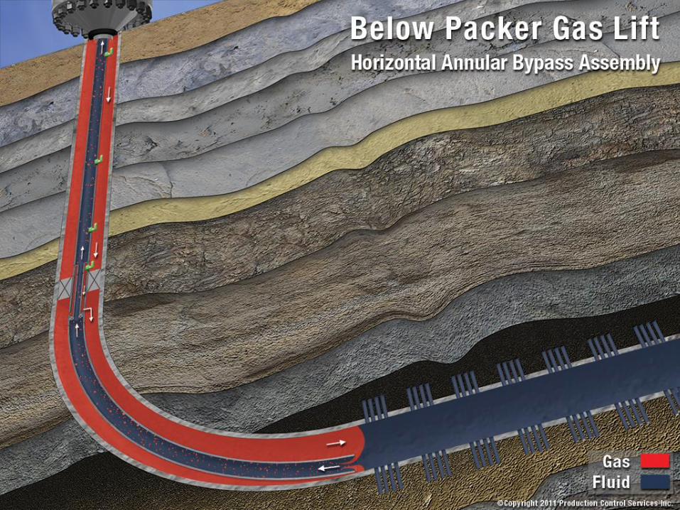
Gas Lift Below the Packer
• The deepest point of injection is no longer limited by the packer
• Gas can be injected below the packer to the most efficient point of lift
• Liquid in the perforated zone is aerated, decreasing the flowing gradient
• Velocity of flow is increased by reducing the effective flow area
Property of PCS Ferguson. All content is confidential to PCS Ferguson and its respective partners.
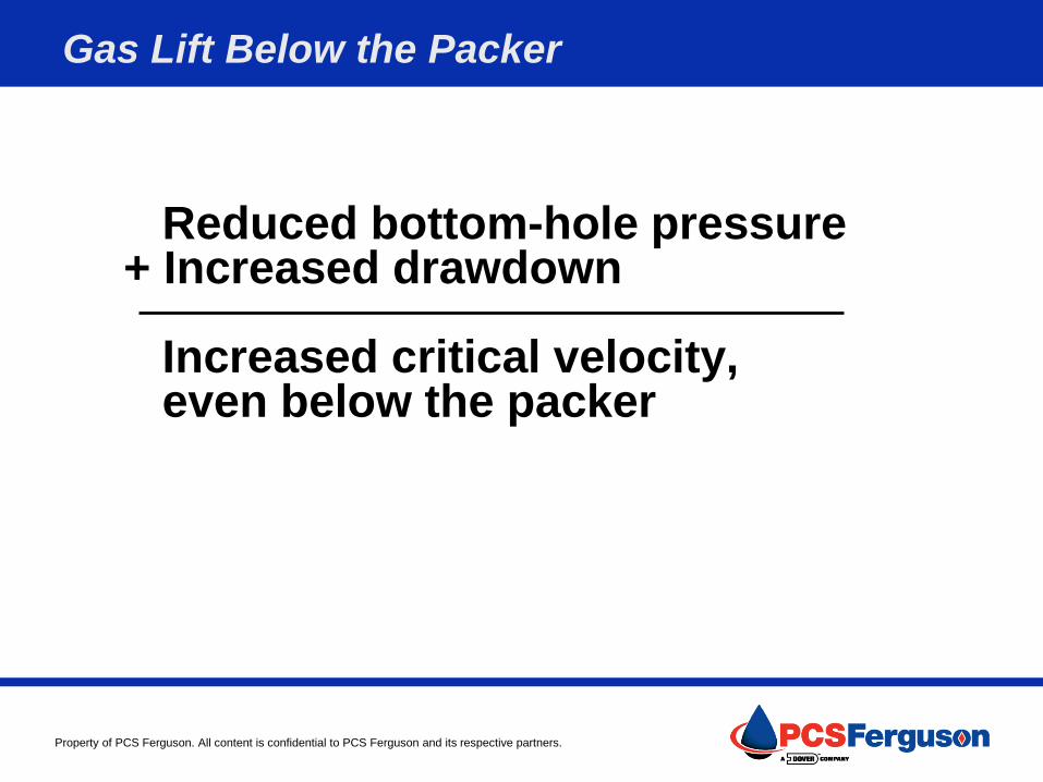
Gas Lift Below the Packer
Reduced bottom-hole pressure + Increased drawdown Increased critical velocity, even below the packer

Property of PCS Ferguson. All content is confidential to PCS Ferguson and its respective partners.
Common Below Packer Installations
• Annular Bypass Assembly (ABA)
• Dip Tube
• Enhanced Annular Velocity (EAV)
• Marathon AVE
Below Packer Gas Lift Types
Property of PCS Ferguson. All content is confidential to PCS Ferguson and its respective partners.
Annular Bypass Assembly (ABA)
• Hybrid of a conventional gas lift system with packer and an
open-ended, packerless system
• Utilizes tubing and gas lift valves above packer and a bypass
assembly through the packer
• Production is normal up the tubing, and no adjustments are
needed on the wellhead
• Ultimate point of lift can be the end of tubing, allowing for
decreased flowing bottom hole pressure compared to a
standard packer completion
• Most applicable where deviation of the wellbore limits how
deep a packer can be set

Property of PCS Ferguson. All content is confidential to PCS Ferguson and its respective partners.
ABA Advantages
• Prevents fluid loading above the packer during
well shut-ins or offset frac activity
• Allows for lift around end of tubing in deviated or
horizontal wells where a packer is desired at a
shallower depth
• Inexpensive system using a gas-lift mandrel and
check for flow cross-over
• Can be used with packer of choice
Property of PCS Ferguson. All content is confidential to PCS Ferguson and its respective partners.

Property of PCS Ferguson. All content is confidential to PCS Ferguson and its respective partners.

Property of PCS Ferguson. All content is confidential to PCS Ferguson and its respective partners.
Dip Tube
• Utilizes a crossover flow adapter and a unique mini well bore
below the packer
• Lift gas travels down the casing annulus above the packer,
through the crossover flow adapter and into the injection string
below the packer
• Production flows up through the crossover flow adapter into
the production tubing and to surface
• Deepest point of injection is achieved without applying back
pressure on the formation
• Able to successfully lift large casing wellbores in perforations
with lesser amounts of compression

Property of PCS Ferguson. All content is confidential to PCS Ferguson and its respective partners.

Property of PCS Ferguson. All content is confidential to PCS Ferguson and its respective partners.

Property of PCS Ferguson. All content is confidential to PCS Ferguson and its respective partners.
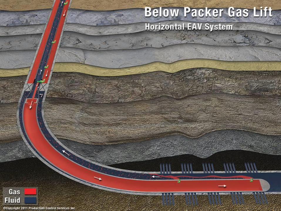
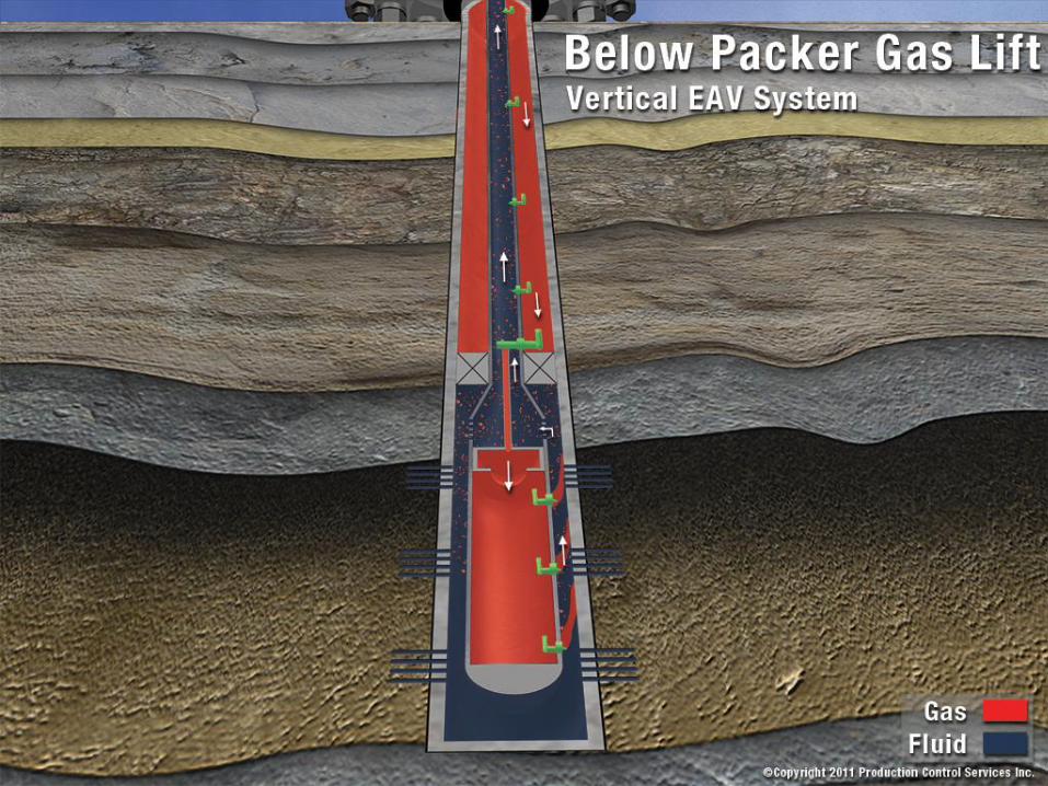
Enhanced Annular Velocity (EAV)
• Utilizes tubing and gas lift valves above packer, and an
injection string with internally mounted gas lift valves below
• Lift gas travels through the casing annulus, through the
crossover flow adapter and into the injection string below the
packer
• Production flows up the annular area, through the crossover
flow adapter and into the production tubing to surface
Property of PCS Ferguson. All content is confidential to PCS Ferguson and its respective partners.
Property of PCS Ferguson. All content is confidential to PCS Ferguson and its respective partners.
Property of PCS Ferguson. All content is confidential to PCS Ferguson and its respective partners.
Marathon AVE
• Similar to EAV, but crossover flow adapter and all gas lift
valves above and below packer are wireline retrievable
• Lift gas travels through the casing annulus, through the
crossover flow adapter and into the injection string below the
packer
• Production flows up the annular area, through the crossover
flow adapter and into the production tubing to surface
• Patented Marathon system

Property of PCS Ferguson. All content is confidential to PCS Ferguson and its respective partners.

Property of PCS Ferguson. All content is confidential to PCS Ferguson and its respective partners.

Property of PCS Ferguson. All content is confidential to PCS Ferguson and its respective partners.
Considerations
• Gas Rate Requirements
– Dip Tube: Example (2-7/8″ x 1-1/4″) 400 MCFD total gas
requirement*
– EAV and Marathon AVE: Example (2-7/8″ or 3-1/2″ x 5-1/2″)
800 - 1,000+ MCFD total gas requirement
– ABA: Example (2-3/8″) 400 MCFD total gas requirement
• Liquid Production (highly variable)
– Dip Tube: lower liquids (average <500 Bbl/d)
– ABA, EAV, Marathon AVE: higher liquids (average >500 Bbl/d)
*Total gas requirement includes compressed gas plus produced gas
Property of PCS Ferguson. All content is confidential to PCS Ferguson and its respective partners.
Other Considerations
• Production Philosophy
– Marathon AVE: planning for inevitable future decline
– Dip Tube, AVE, EAV: dealing with today’s production issues
• Other Variables to Consider
– Geometry of the wellbore: Toe-Up, Toe-Down, Deviated or Vertical
– Declining reservoir pressure
– Producing well head pressure
– Current flowing bottom hole pressure

Property of PCS Ferguson. All content is confidential to PCS Ferguson and its respective partners.
Conclusion
• More wells are being drilled and completed with long perforated
intervals
• Gas lift is cost-effective and flexible to meet changing
conditions
• Recent gas lift innovations can now achieve deeper point of
injection below the packer
• These systems create adequate velocity below the packer to
recover fluids, reducing flowing bottom hole pressure and
increasing drawdown
For more information, please visit us at
www.pcsferguson.com