Embed Size (px)
Citation preview

Opti-Flow™ Gas Lift
by
Often a well does not have sufficient natural energy to move liquids to the surface at desired rates. Changing well conditions, such as reduced reservoir pressure, increasing water cuts and decreasing gas liquid ratios can make consistent and predictable production a challenge. You need a means of artificial lift that is flexible enough to optimize production throughout the life of the well—from initial kick-off to depletion.
YOU NEED OPTI-FLOW™ GAS LIFT FROM PCS FERGUSON.
Optimizing production throughout the entire lifespan of the well.
The benefiTs of opTi-flow Gas lifT include:
• Unrivaled ability to accommodate various well characteristics
• Superior design process that accounts for current and future conditions
• Flexible artificial lift solution for the life of the well
• Full range of equipment to meet your specific needs
• Can be used to assist plunger lift
Capable of producing wells with a range of flow rates, Opti-Flow Gas Lift is an extremely flexible artificial lift solution that can be used throughout the lifespan of the well. There are many instances where gas lift is both effective and economical, including:
• Producingwellsthatcan’tflownaturally
• Initialunloadingofawellthatwillflow
• Increasingtheproductionrateofaflowingwell
• Accommodatingdeviatedandhorizontalwellbores
• Removingsolidsbybackflowing
• Producingwellswithsandandscaleproblems
2
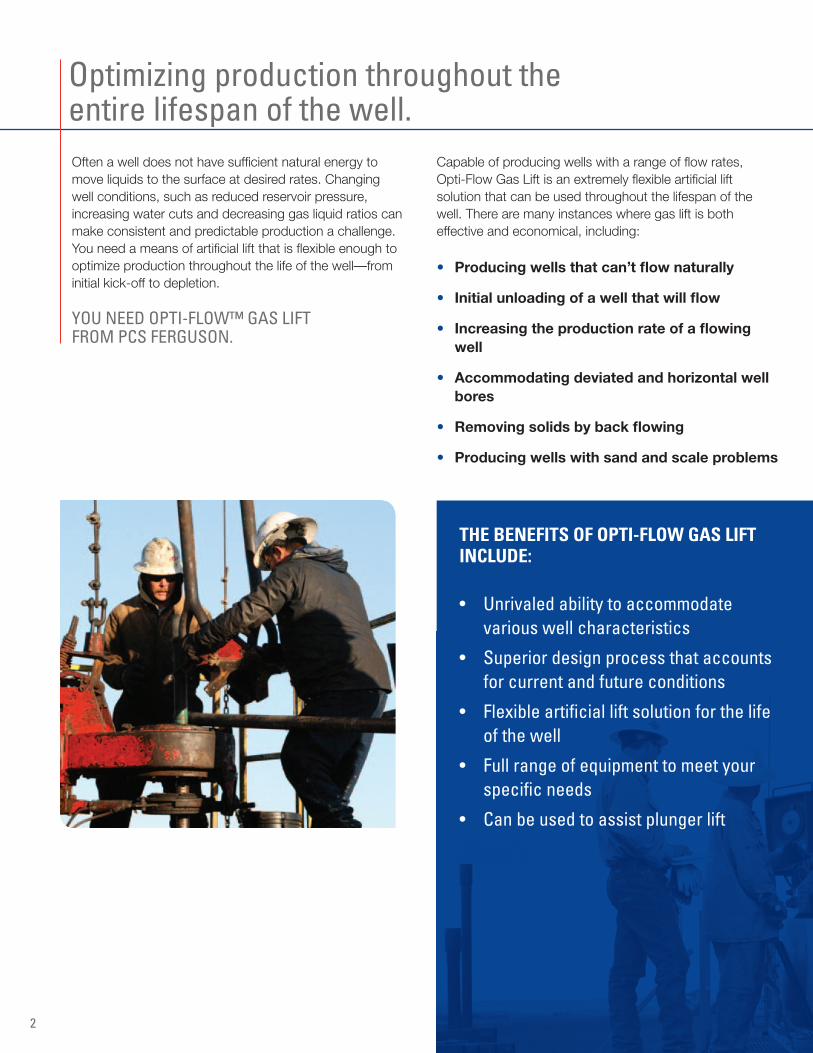
The success of gas lift is largely dependent upon the initial design of the system. Installation of Opti-Flow Gas Lift begins with a carefully engineered design using OPTIpod, our gas lift design software. Using a number of well characteristics, OPTIpod helps determine the optimal amount of gas needed to deliver fluids to the surface and the best locations in the production string, based on pressure, for the gas to be injected. These determinations are critical, as identifying the proper points of injection is the key to optimal production.
While our software is a central component of system design, the experience and expertise of our personnel is the real key to the success of Opti-Flow Gas Lift systems. With more than 30 years of experience designing, installing and troubleshooting gas lift, our production experts have the experience and know-how to design systems for a variety of well conditions and deliver the best possible production outcomes.
Design plus expertise equals success.
3
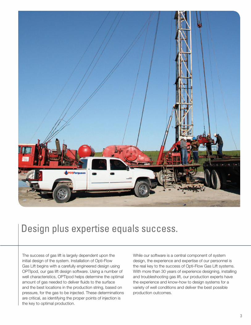
Gas lift uses a high-pressure source to inject gas down the annulus and into the tubing string. The gas is injected through gas lift valves, which are housed in gas lift mandrels. The mandrels are installed at specific intervals in the tubing as determined by the design of the system, downward to the lowest point possible.
The gas lift valves open and close based on preset pressure settings. When open, they allow gas to be injected into the production string. They also allow liquids to escape the casing when using gas lift to initially unload a well.
As the gas flows to the surface, it expands, reducing the density and column weight of the fluid. By reducing the flowing tubing pressure, differential pressure between the reservoir and the well bore is created, allowing the well to flow.
FIGURE 1• Gasinjectionintothecasinghasbegun
• Fluidisu-tubedthroughallopenvalves
• Noformationfluidsbeingproduced;allfluidsarefromthetubingandcasing
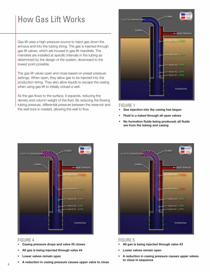
FIGURE 5• Allgasisbeinginjectedthroughvalve#3
• Lowervalvesremainopen
• Areductionincasingpressurecausesuppervalvestocloseinsequence
FIGURE 4• Casingpressuredropsandvalve#5closes
• Allgasisbeinginjectedthroughvalve#4
• Lowervalvesremainopen
• Areductionincasingpressurecausesuppervalvetoclose
How Gas Lift Works
4
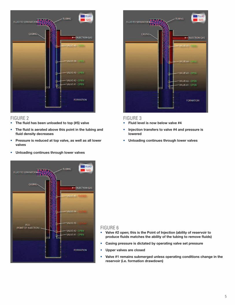
FIGURE 2• Thefluidhasbeenunloadedtotop(#5)valve
• Thefluidisaeratedabovethispointinthetubingandfluiddensitydecreases
• Pressureisreducedattopvalve,aswellasalllowervalves
• Unloadingcontinuesthroughlowervalves
FIGURE 3• Fluidlevelisnowbelowvalve#4
• Injectiontransferstovalve#4andpressureislowered
• Unloadingcontinuesthroughlowervalves
FIGURE 6• Valve#2open;thisisthePointofInjection(abilityofreservoirto
producefluidsmatchestheabilityofthetubingtoremovefluids)
• Casingpressureisdictatedbyoperatingvalvesetpressure
• Uppervalvesareclosed
• Valve#1remainssubmergedunlessoperatingconditionschangeinthereservoir(i.e.formationdrawdown)
5
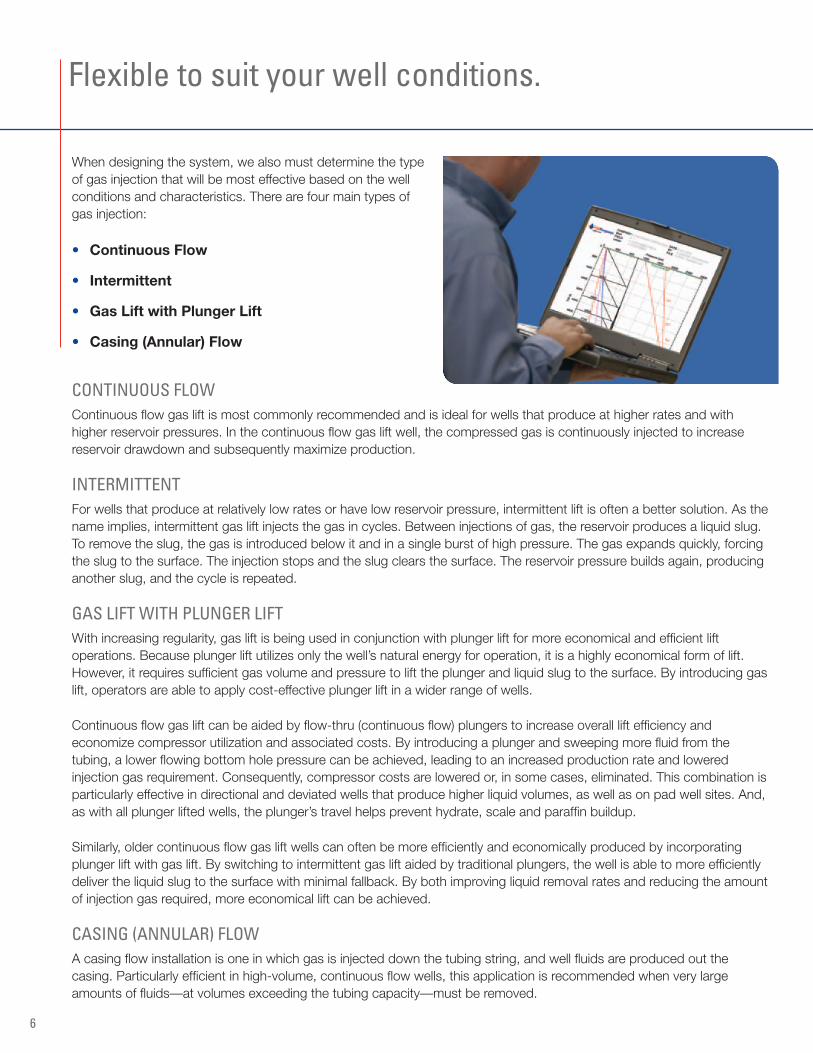
When designing the system, we also must determine the type of gas injection that will be most effective based on the well conditions and characteristics. There are four main types of gas injection:
• ContinuousFlow
• Intermittent
• GasLiftwithPlungerLift
• Casing(Annular)Flow
CONTINUOUS FLOWContinuous flow gas lift is most commonly recommended and is ideal for wells that produce at higher rates and with higher reservoir pressures. In the continuous flow gas lift well, the compressed gas is continuously injected to increase reservoir drawdown and subsequently maximize production.
INTERMITTENT For wells that produce at relatively low rates or have low reservoir pressure, intermittent lift is often a better solution. As the name implies, intermittent gas lift injects the gas in cycles. Between injections of gas, the reservoir produces a liquid slug. To remove the slug, the gas is introduced below it and in a single burst of high pressure. The gas expands quickly, forcing the slug to the surface. The injection stops and the slug clears the surface. The reservoir pressure builds again, producing another slug, and the cycle is repeated.
GAS LIFT WITH PLUNGER LIFTWith increasing regularity, gas lift is being used in conjunction with plunger lift for more economical and efficient lift operations. Because plunger lift utilizes only the well’s natural energy for operation, it is a highly economical form of lift. However, it requires sufficient gas volume and pressure to lift the plunger and liquid slug to the surface. By introducing gas lift, operators are able to apply cost-effective plunger lift in a wider range of wells.
Continuous flow gas lift can be aided by flow-thru (continuous flow) plungers to increase overall lift efficiency and economize compressor utilization and associated costs. By introducing a plunger and sweeping more fluid from the tubing, a lower flowing bottom hole pressure can be achieved, leading to an increased production rate and lowered injection gas requirement. Consequently, compressor costs are lowered or, in some cases, eliminated. This combination is particularly effective in directional and deviated wells that produce higher liquid volumes, as well as on pad well sites. And, as with all plunger lifted wells, the plunger’s travel helps prevent hydrate, scale and paraffin buildup.
Similarly, older continuous flow gas lift wells can often be more efficiently and economically produced by incorporating plunger lift with gas lift. By switching to intermittent gas lift aided by traditional plungers, the well is able to more efficiently deliver the liquid slug to the surface with minimal fallback. By both improving liquid removal rates and reducing the amount of injection gas required, more economical lift can be achieved.
CASING (ANNULAR) FLOWA casing flow installation is one in which gas is injected down the tubing string, and well fluids are produced out the casing. Particularly efficient in high-volume, continuous flow wells, this application is recommended when very large amounts of fluids—at volumes exceeding the tubing capacity—must be removed.
Flexible to suit your well conditions.
6
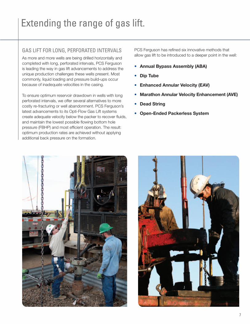
GAS LIFT FOR LONG, PERFORATED INTERvALSAs more and more wells are being drilled horizontally and completed with long, perforated intervals, PCS Ferguson is leading the way in gas lift advancements to address the unique production challenges these wells present. Most commonly, liquid loading and pressure build-ups occur because of inadequate velocities in the casing.
To ensure optimum reservoir drawdown in wells with long perforated intervals, we offer several alternatives to more costly re-fracturing or well abandonment. PCS Ferguson’s latest advancements to its Opti-Flow Gas Lift systems create adequate velocity below the packer to recover fluids, and maintain the lowest possible flowing bottom hole pressure (FBHP) and most efficient operation. The result: optimum production rates are achieved without applying additional back pressure on the formation.
PCS Ferguson has refined six innovative methods that allow gas lift to be introduced to a deeper point in the well:
• AnnualBypassAssembly(ABA)
• DipTube
• EnhancedAnnularVelocity(EAV)
• MarathonAnnularVelocityEnhancement(AVE)
• DeadString
• Open-EndedPackerlessSystem
Extending the range of gas lift.
7
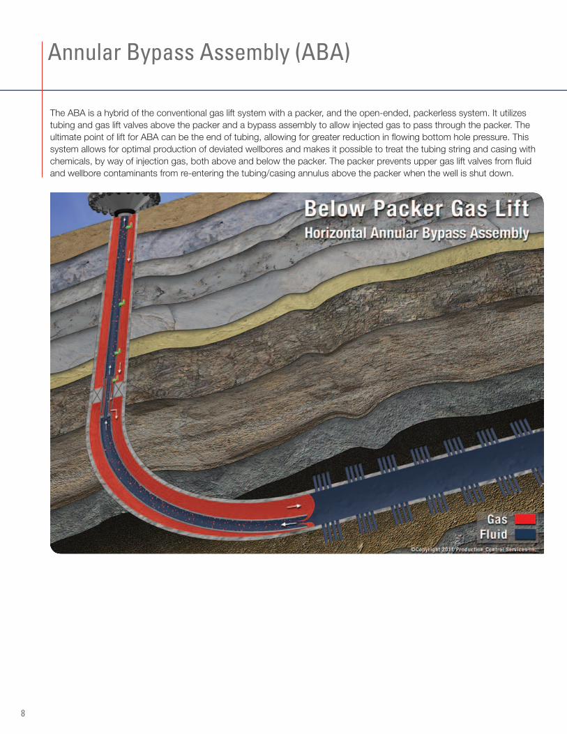
The ABA is a hybrid of the conventional gas lift system with a packer, and the open-ended, packerless system. It utilizes tubing and gas lift valves above the packer and a bypass assembly to allow injected gas to pass through the packer. The ultimate point of lift for ABA can be the end of tubing, allowing for greater reduction in flowing bottom hole pressure. This system allows for optimal production of deviated wellbores and makes it possible to treat the tubing string and casing with chemicals, by way of injection gas, both above and below the packer. The packer prevents upper gas lift valves from fluid and wellbore contaminants from re-entering the tubing/casing annulus above the packer when the well is shut down.
Annular Bypass Assembly (ABA)
8
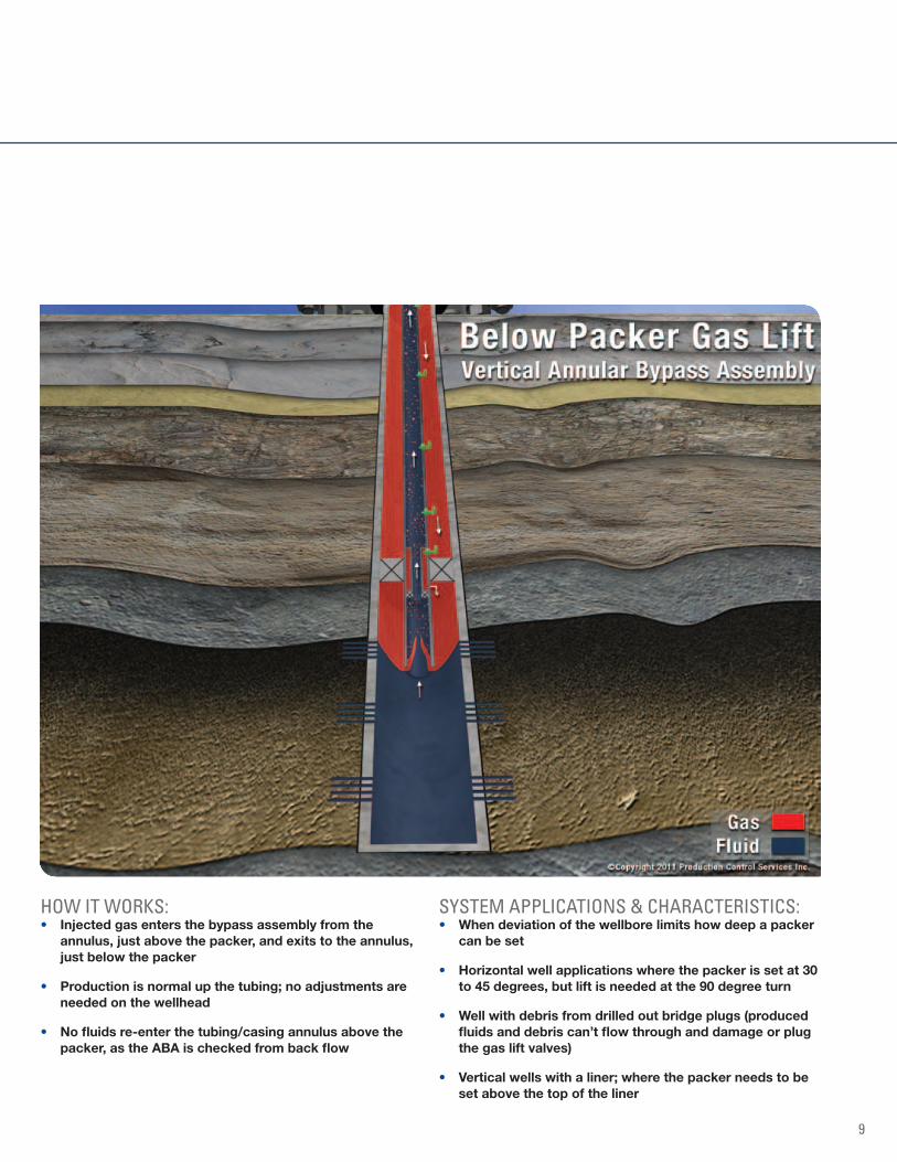
HOW IT WORkS:• Injectedgasentersthebypassassemblyfromthe
annulus,justabovethepacker,andexitstotheannulus,justbelowthepacker
• Productionisnormalupthetubing;noadjustmentsareneededonthewellhead
• Nofluidsre-enterthetubing/casingannulusabovethepacker,astheABAischeckedfrombackflow
SYSTEM APPLICATIONS & CHARACTERISTICS:• Whendeviationofthewellborelimitshowdeepapacker
canbeset
• Horizontalwellapplicationswherethepackerissetat30to45degrees,butliftisneededatthe90degreeturn
• Wellwithdebrisfromdrilledoutbridgeplugs(producedfluidsanddebriscan’tflowthroughanddamageorplugthegasliftvalves)
• Verticalwellswithaliner;wherethepackerneedstobesetabovethetopoftheliner
9
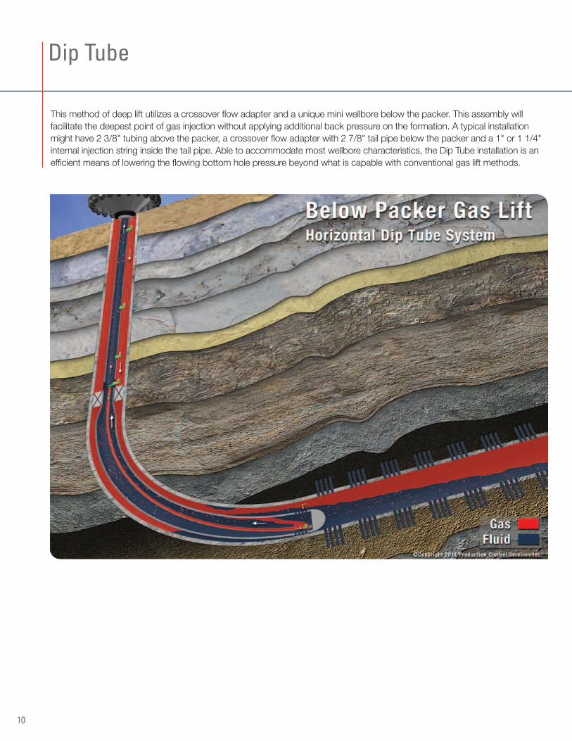
This method of deep lift utilizes a crossover flow adapter and a unique mini wellbore below the packer. This assembly will facilitate the deepest point of gas injection without applying additional back pressure on the formation. A typical installation might have 2 3/8" tubing above the packer, a crossover flow adapter with 2 7/8" tail pipe below the packer and a 1" or 1 1/4" internal injection string inside the tail pipe. Able to accommodate most wellbore characteristics, the Dip Tube installation is an efficient means of lowering the flowing bottom hole pressure beyond what is capable with conventional gas lift methods.
Dip Tube
10
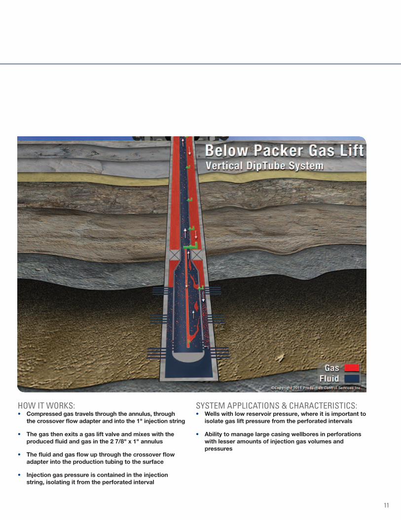
HOW IT WORkS:• Compressedgastravelsthroughtheannulus,through
thecrossoverflowadapterandintothe1"injectionstring
• Thegasthenexitsagasliftvalveandmixeswiththeproducedfluidandgasinthe27/8"x1"annulus
• Thefluidandgasflowupthroughthecrossoverflowadapterintotheproductiontubingtothesurface
• Injectiongaspressureiscontainedintheinjectionstring,isolatingitfromtheperforatedinterval
SYSTEM APPLICATIONS & CHARACTERISTICS:• Wellswithlowreservoirpressure,whereitisimportantto
isolategasliftpressurefromtheperforatedintervals
• Abilitytomanagelargecasingwellboresinperforationswithlesseramountsofinjectiongasvolumesandpressures
11
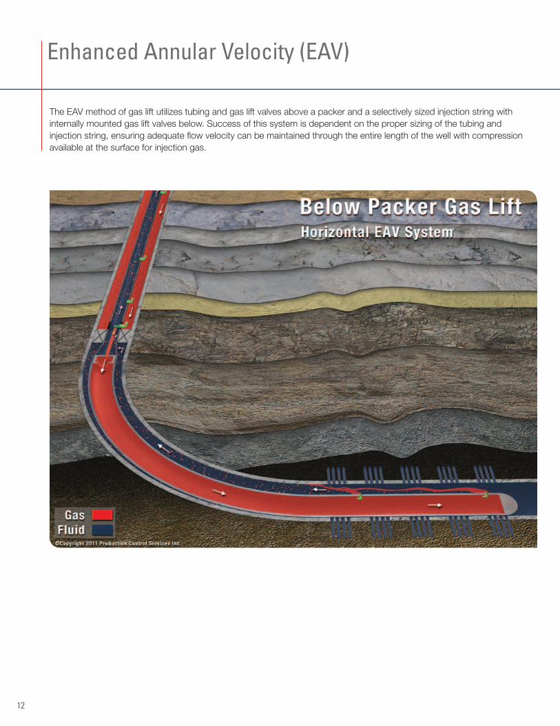
The EAV method of gas lift utilizes tubing and gas lift valves above a packer and a selectively sized injection string with internally mounted gas lift valves below. Success of this system is dependent on the proper sizing of the tubing and injection string, ensuring adequate flow velocity can be maintained through the entire length of the well with compression available at the surface for injection gas.
Enhanced Annular velocity (EAv)
12
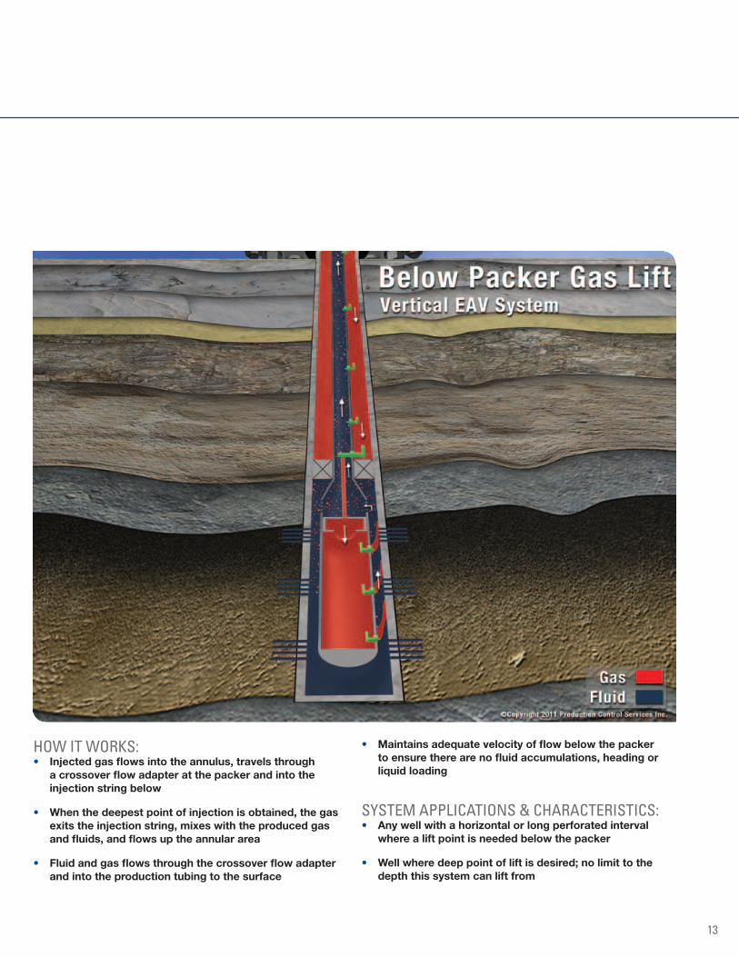
HOW IT WORkS:• Injectedgasflowsintotheannulus,travelsthrough
acrossoverflowadapteratthepackerandintotheinjectionstringbelow
• Whenthedeepestpointofinjectionisobtained,thegasexitstheinjectionstring,mixeswiththeproducedgasandfluids,andflowsuptheannulararea
• Fluidandgasflowsthroughthecrossoverflowadapterandintotheproductiontubingtothesurface
• Maintainsadequatevelocityofflowbelowthepackertoensuretherearenofluidaccumulations,headingorliquidloading
SYSTEM APPLICATIONS & CHARACTERISTICS:• Anywellwithahorizontalorlongperforatedinterval
wherealiftpointisneededbelowthepacker
• Wellwheredeeppointofliftisdesired;nolimittothedepththissystemcanliftfrom
13

Once thought impossible, a wireline retrievable AVE (similar to the EAV) system has been patented by Marathon and is exclusively sold and manufactured by PCS Ferguson. This nontraditional system allows for gas injection through an injection string below the packer similar to the EAV system, but offers the advantage of being wireline retrievable. The entire crossover flow adapter assembly and all gas lift valves above and below the packer are accessible and retrievable by wireline.
Marathon Annular velocity Enhancement (AvE)
14
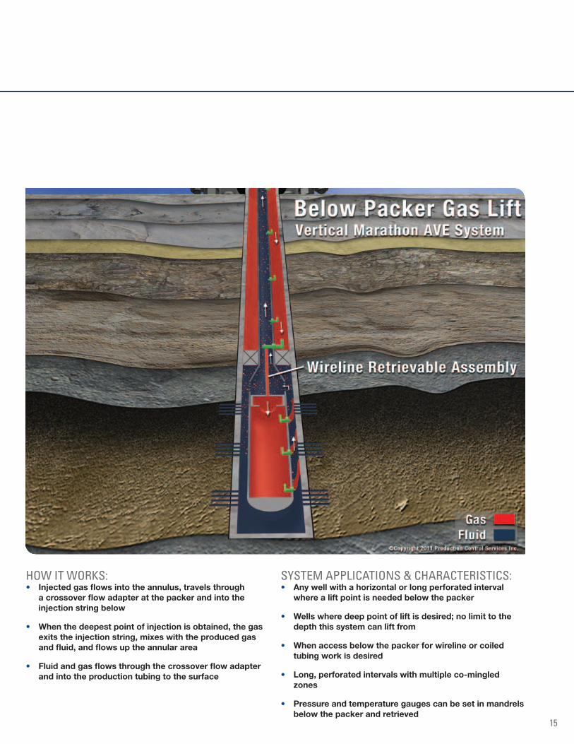
HOW IT WORkS:• Injectedgasflowsintotheannulus,travelsthrough
acrossoverflowadapteratthepackerandintotheinjectionstringbelow
• Whenthedeepestpointofinjectionisobtained,thegasexitstheinjectionstring,mixeswiththeproducedgasandfluid,andflowsuptheannulararea
• Fluidandgasflowsthroughthecrossoverflowadapterandintotheproductiontubingtothesurface
SYSTEM APPLICATIONS & CHARACTERISTICS:• Anywellwithahorizontalorlongperforatedinterval
wherealiftpointisneededbelowthepacker
• Wellswheredeeppointofliftisdesired;nolimittothedepththissystemcanliftfrom
• Whenaccessbelowthepackerforwirelineorcoiledtubingworkisdesired
• Long,perforatedintervalswithmultipleco-mingledzones
• Pressureandtemperaturegaugescanbesetinmandrelsbelowthepackerandretrieved
15
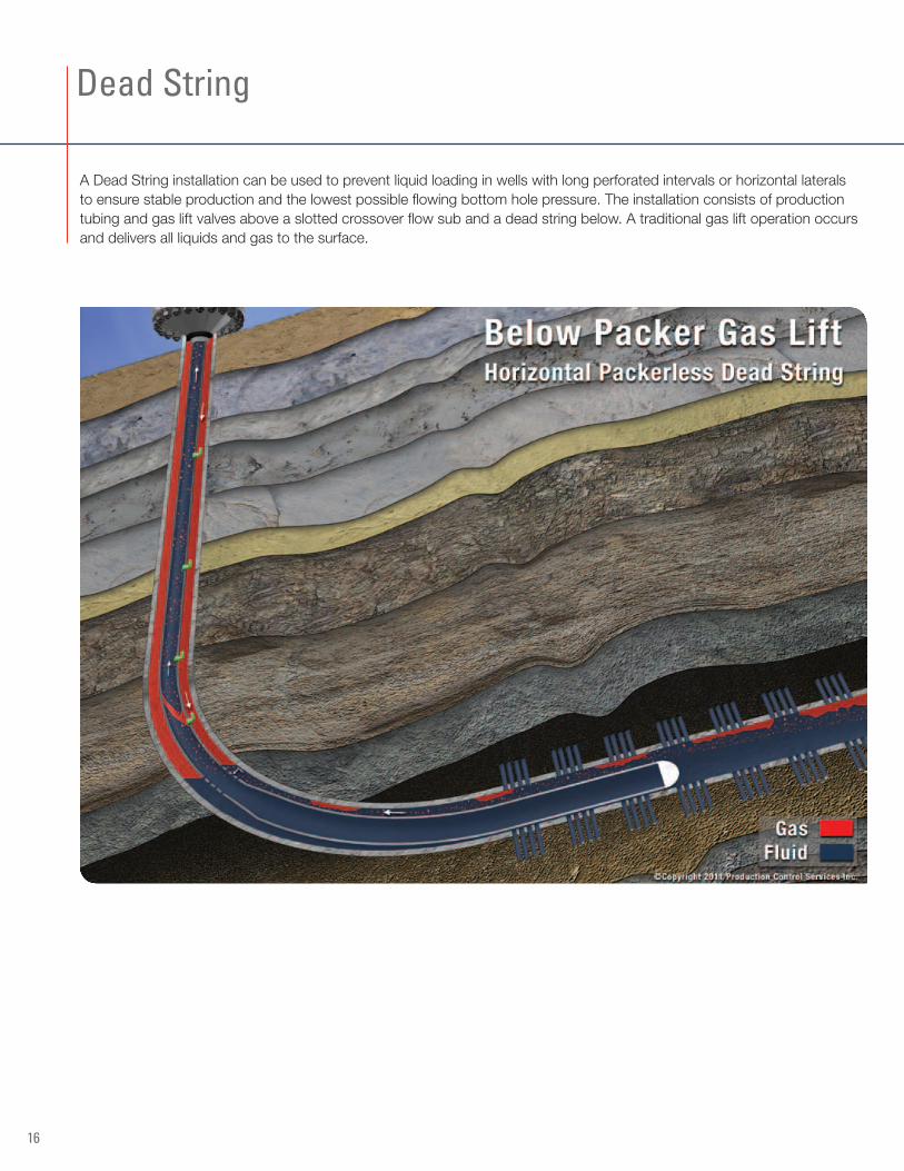
A Dead String installation can be used to prevent liquid loading in wells with long perforated intervals or horizontal laterals to ensure stable production and the lowest possible flowing bottom hole pressure. The installation consists of production tubing and gas lift valves above a slotted crossover flow sub and a dead string below. A traditional gas lift operation occurs and delivers all liquids and gas to the surface.
Dead String
16
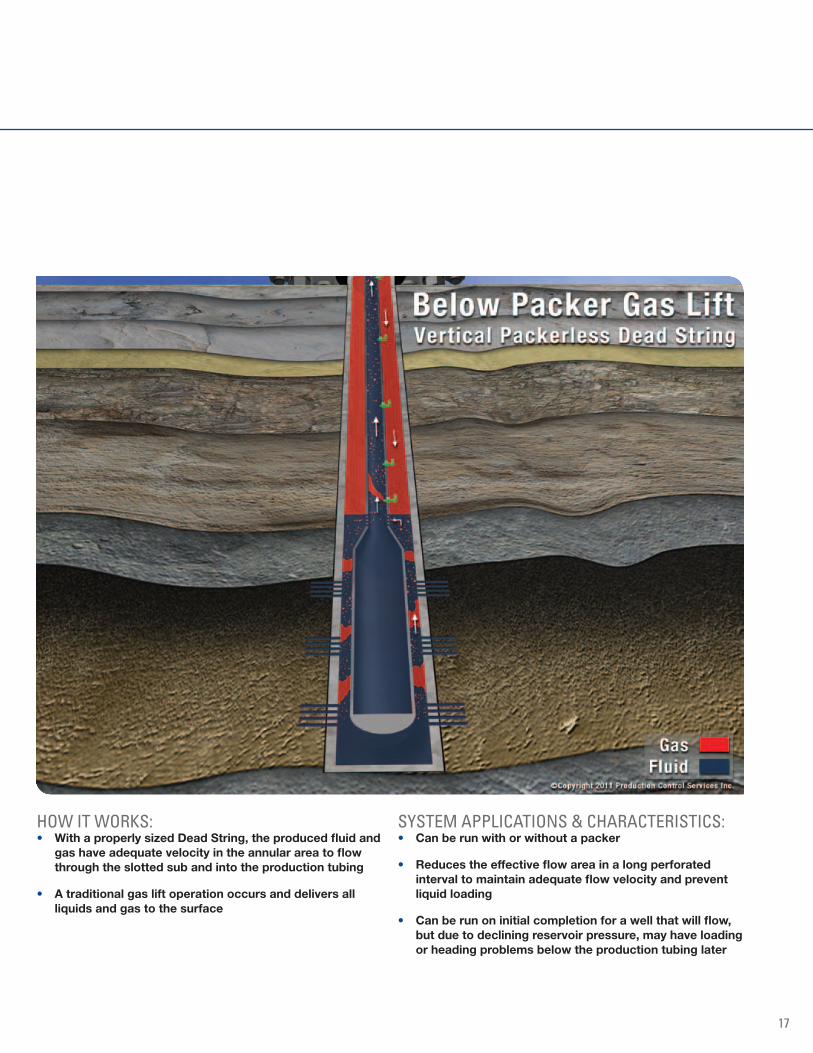
HOW IT WORkS:• WithaproperlysizedDeadString,theproducedfluidand
gashaveadequatevelocityintheannularareatoflowthroughtheslottedsubandintotheproductiontubing
• Atraditionalgasliftoperationoccursanddeliversallliquidsandgastothesurface
SYSTEM APPLICATIONS & CHARACTERISTICS:• Canberunwithorwithoutapacker
• Reducestheeffectiveflowareainalongperforatedintervaltomaintainadequateflowvelocityandpreventliquidloading
• Canberunoninitialcompletionforawellthatwillflow,butduetodecliningreservoirpressure,mayhaveloadingorheadingproblemsbelowtheproductiontubinglater
17
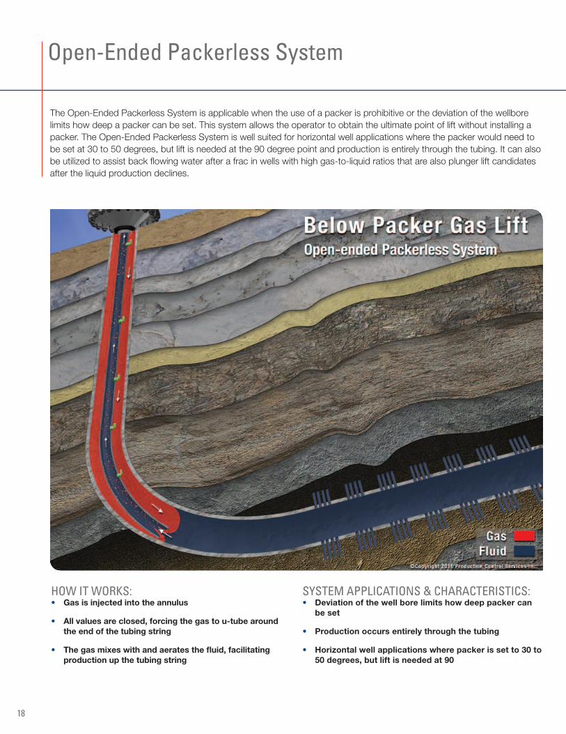
The Open-Ended Packerless System is applicable when the use of a packer is prohibitive or the deviation of the wellbore limits how deep a packer can be set. This system allows the operator to obtain the ultimate point of lift without installing a packer. The Open-Ended Packerless System is well suited for horizontal well applications where the packer would need to be set at 30 to 50 degrees, but lift is needed at the 90 degree point and production is entirely through the tubing. It can also be utilized to assist back flowing water after a frac in wells with high gas-to-liquid ratios that are also plunger lift candidates after the liquid production declines.
Open-Ended Packerless System
18
HOW IT WORkS:• Gasisinjectedintotheannulus
• Allvaluesareclosed,forcingthegastou-tubearoundtheendofthetubingstring
• Thegasmixeswithandaeratesthefluid,facilitatingproductionupthetubingstring
SYSTEM APPLICATIONS & CHARACTERISTICS:• Deviationofthewellborelimitshowdeeppackercan
beset
• Productionoccursentirelythroughthetubing
• Horizontalwellapplicationswherepackerissetto30to50degrees,butliftisneededat90
Partnering with PCS Ferguson
PCS Ferguson is the result of two artificial lift and production optimization leaders joining forces to offer oil and gas producers world-class deliquification and well control expertise. Building on the values that drove our individual success, we will continue to deliver the technical expertise, quality products and responsive service that you’ve come to expect.
Here are just a few of the benefits of working with PCS Ferguson:
• Decadesofexperiencerecommendingandservicingliftsystemstoaccommodatechangingwellconditions
• Unrivaledexpertiseinplungerlift,gaslift,wellcontrolandwellunloading
• Thebestperformingandhighestqualityproductsdesigned,engineeredandmanufacturedin-houseatourColoradoandTexasfacilities
• Experiencedandresponsivefieldsupportstaffwithextensivelocalknowledge
• Thehighestcommitmenttotheprotectionandsafetyofouremployees,ourcustomersandtheenvironment
• Comprehensivecustomertrainingandproductsupport
At PCS Ferguson, our mission is simple: to provide superior products and unrivaled service that optimize your production and quickly impact your bottom line.
To learn more about Opti-Flow Gas Lift by PCS Ferguson or our complete lineup of well optimization products and services, please contact your local sales and service representative or visit us online at www.pcsferguson.com
19

At PCS Ferguson, we know our success is dependent upon yours. Our primary focus is—and has been for more than three decades—to more efficiently and effectively optimize the production of each of our customers’ assets. The end result for you: better, more efficient, more cost-effective production that clearly and quickly impacts your bottom line.
For more information about our products and services, please contact your local PCS Ferguson sales and service office or visit us on the web at: www.pcsferguson.com
CorporateHeadquartersFrederick, Colorado .......720.407.3550
CanadaSalesOfficesCalgary, AB ...................403.266.6139Claresholm, AB ..............403.625.4105Consort, AB ..................403.577.2519Drayton Valley, AB .........780.514.5206Edson, AB .....................780.723.2759Grand Prairie, AB ...........780.539.7773Red Deer, AB .................403.340.3605
ArkansasSalesOfficeConway .........................501.932.0449
ColoradoSalesOfficesDenver ...........................303.886.5216Evans ............................970.539.9003Fort Lupton ...................303.857.1522Grand Junction ..............970.241.7177Parachute ......................970.285.9652
LouisianaSalesOfficesBossier City ...................318.747.0130Haynesville ....................318.464.8134Lafayette .......................337.886.0009
NewMexicoSalesOfficeFarmington ....................505.326.4239
NorthDakotaSalesOfficeMinot .............................701.566.3278
OklahomaSalesOfficesOklahoma City ...............405.440.1015Stigler ............................918.967.3236Woodward .....................580.256.1317
PennsylvaniaSalesOfficesCoraopolis .....................412.264.6000Duboistown ...................570.327.1750
TexasSalesOfficesAmarillo .........................903.520.9612Bridgeport .....................940.683.3898Buffalo ...........................903.322.9300Cleburne .......................817.641.9900Fort Stockton ................432.336.6622Fort Worth .....................817.244.0238Freer ..............................361.876.0889Houston ........................281.350.2084Kenedy ..........................830.583.9900Karnes City ....................903.984.5155Midland-Odessa ............432.563.1012Perryton ........................405.213.8114Sonora ..........................325.387.6260Tyler ...............................903.561.4851Weatherford ...................817.599.6570
UtahSalesOfficeVernal ............................435.789.2031
WyomingSalesOfficesGillette ...........................307.686.9594Rock Springs .................307.362.6010
© 2013 Production Control Services, Inc. (dba PCS Ferguson). All Rights Reserved. DOVER® and the DOVER® Logo are registered trademarks in the United States and various other countries of Delaware Capital Formation, Inc., a wholly-owned subsidiary of Dover Corporation.